

Page 1

EZ-IP TURRET/DOME NETWORK CAMERA
QUICK START GUIDE
Version 1.0.2
Dahua Vision Technology Co., LTD
ENPLRO DE
Page 2

Page 3

Bedienungsanleitung
Vielen Dank, dass Sie sich für unsere Netzwerk-Kamera entschieden haben.
Diese Bedienungsanleitung dient als Referenzwerkzeug für die Verwendung
Ihres Produkts.
Bitte lesen Sie die folgenden Sicherheitshinweise und Warnungen sorgfältig
durch, bevor Sie dieses Serienprodukt verwenden.
Bitte bewahren Sie diese Bedienungsanleitung sorgfältig auf für späteres
nachschlagen.
Wichtige Sicherheitshinweise und Warnungen
Elektrische Sicherheit
• Die gesamte Installation und der Betrieb sollten den örtlichen
Sicherheitsvorschriften entsprechen.
• Die Stromquelle muss den Anforderungen der SELV Norm (Safety Extra Low
Voltage - Kleinspannung) entsprechen und die Stromversorgung mit einer
Nennspannung liefern, die den Anforderungen der begrenzten Stromquelle
gemäß IEC60950-1 entspricht. Bitte beachten Sie, dass die Anforderungen
an die Stromversorgung auf dem Typenschild benden.
• Stellen Sie sicher, dass die Stromversorgung korrekt ist, bevor Sie das Gerät
in Betrieb nehmen.
• Verhindern Sie, dass das Netzkabel mit Füßen getreten oder gedrückt
wird, insbesondere Stecker, Steckdose und Anschluss, die aus dem Gerät
herausragen.
• Wir übernehmen keine Haftung oder Verantwortung für Brände oder
Stromschläge, die durch unsachgemäße Handhabung oder Installation
verursacht werden.
Umgebung
• Richten Sie das Gerät nicht auf starkes Licht scharf aus, z. B. Lampenlicht
und Sonnenlicht. Andernfalls kann es zu Überhellungen oder Lichtecken
kommen, die keine Fehlfunktion des Geräts darstellen, und die Lebensdauer
von CMOS (Complementary Metal-Oxide Semiconductor) beeinträchtigen.
• Stellen Sie das Gerät nicht in einer feuchten oder staubigen Umgebung,
extrem heißen oder kalten Temperaturen oder an Orten mit starker
elektromagnetischer Strahlung auf. Stellen Sie das Gerät nicht an Orten auf,
an denen es direkter Sonneneinstrahlung oder unstabiles Licht ausgesetzt ist.
• Sorgen Sie für gute Belüftung, um Wärmestau zu vermeiden.
• Transportieren, verwenden und lagern Sie das Gerät innerhalb der zulässigen
Luftfeuchtigkeit und Temperatur.
• Während des Transports, der Lagerung und der Installation dürfen keine
schweren Belastungen, heftigen Vibrationen oder Wasserspritzer auftreten.
• Verpacken Sie das Gerät mit einer Standard-Werksverpackung oder
DE
3
Page 4

Bedienungsanleitung Bedienungsanleitung
gleichwertigem Material, wenn Sie das Gerät transportieren.
Bedienung und tägliche Wartung
• Zerlegen Sie das Gerät nicht, da es keine Komponente gibt, die vom Benutzer
selbst repariert werden kann. Anderenfalls kann es zu Wassereindringen
oder schlechte Bildqualität kommen, wegen unprofessionelles zerlegen.
• Wenn sich Feuchtigkeit oder Nebel in den Internen Komponenten der
Kamera bendet, wenden Sie sich an einen autorisierten Kundendienst.
• Es wird empfohlen, das Gerät zusammen mit einem Blitzschutz zu
verwenden, um den Blitzschutz zu verbessern.
• Reinigen Sie das Gerät mit einem weichen, leicht angefeuchteten Tuch. Wenn
der Staub schwer zu entfernen ist, wischen Sie ihn bitte mit einem sauberen
Tuch ab, das leicht mit einem milden Reinigungsmittel angefeuchtet ist und
reinigen das Gerät anschließend mit einem trockenen Tuch. Verwenden
Sie keine üchtigen Lösungsmittel wie Alkohol, Benzin, Verdünner oder
starke Reinigungsmittel mit Abrieb, da sonst die Oberächenbeschichtung
beschädigt wird.
• Wir haften nicht für Probleme, die durch nicht autorisierte Änderungen oder
Reparatur-Versuche verursacht wurden.
• Sie können den Staub mit einer Luftpistole entfernen, wenn die Abdeckung
mit Staub verschmutzt ist.
• Dieses Gerät kann von Kindern ab 8 Jahren und von Personen mit
eingeschränkten körperlichen, sensorischen oder geistigen Fähigkeiten oder
mangelnden Erfahrungen und Kenntnissen verwendet werden, wenn sie
von einer Person beaufsichtigt und geleitet werden, die in einer vorsichtigen
Weise für ihre Sicherheit verantwortlich ist und alle Sicherheitsvorkehrungen
verstanden hat und befolgt. Kinder sollten nicht mit diesem Gerät spielen.
Kinder dürfen das Gerät nicht unbeaufsichtigt reinigen und warten.
Warnungen
• Schützen Sie das Gerät vor unbefugtem Zugang, durch starke Passwörter
und regelmäßiges Aktualisieren der Firmware auf die neueste Version.
DE
• Der Benutzer muss sofort nach dem Anmelden, sein eigenes Passwort
einrichten.
• Verwenden Sie die vom Hersteller bereitgestellten Standardkomponenten,
und stellen sicher, dass das Gerät von Fachingenieuren installiert und
repariert wird.
• Die Oberäche des Bildsensors sollte in einer Umgebung, in der ein
Laserstrahlgerät verwendet wird, keiner Laserstrahlung ausgesetzt werden.
• Stellen Sie nicht zwei oder mehr Stromquellen gleichzeitig für das Gerät
bereit. Andernfalls kann das Gerät beschädigt werden (Stromversorgung
und PoE gleichzeitig).
Haftungsausschluss
4 5
Page 5

• Diese Bedienungsanleitung dient nur als Referenz. Bitte beziehen Sie sich
auf das tatsächliche Produkt für weitere Details.
• Der Hersteller haftet nicht für Schäden, die durch unangemessenen
Gebrauch des Geräts verursacht werden.
• In der Benutzeroberäche können geringfügige Unterschiede gefunden
werden und es kann Abweichungen zwischen dem tatsächlichen Wert einiger
Daten und dem in der Bedienungs-Anleitung angegebenen Wert geben, weil
die reale Umgebung nicht stabil ist. Bitte wenden Sie sich bei Zweifeln oder
Streitigkeiten an die abschließende Erklärung des Unternehmens.
• Alle Designs und Software können ohne vorherige Ankündigung geändert
werden. Die Bedienungs-Anleitung wird regelmäßig entsprechend der
Produktaktualisierung ohne vorherige Ankündigung aktualisiert.
• Wenden Sie sich an den Lieferanten oder den Kundendienst, wenn bei der
Verwendung des Geräts Probleme aufgetreten sind.
• Bitte wenden Sie sich an den Kundendienst, um sich über das neueste
Verfahren und zusätzliche Dokumentation zu informieren.
• Bitte besuchen Sie die Website www.lechpol.com oder wenden sich an Ihren
lokalen Servicetechniker, um weitere Informationen zu erhalten.
• Das Unternehmen haftet nicht für Schäden, die durch den Betrieb verursacht
werden, der nicht der Bedienungsanleitung entspricht.
• Bei Unsicherheiten oder Kontroversen verweisen wir auf unsere
abschließende Erklärung.
Hinweis
• Weitere Informationen nden Sie auf der CD.
• Önen Sie vor der Installation das Paket und überprüfen, ob alle
Komponenten enthalten sind. Wenden Sie sich so schnell wie möglich an
Ihren Händler, wenn in Ihrem Paket etwas defekt ist.
Zubehörname Anzahl
Netzwerk Kameraeinheit 1
Schnellstartanleitung 1
Wasserdichter Stecker 1
Schraubenpaket 1
CD 1
Table 1-1
DE
Page 6
Bedienungsanleitung Bedienungsanleitung
1. Rahmen
1.1 Externe Gerätekabel
Hinweis
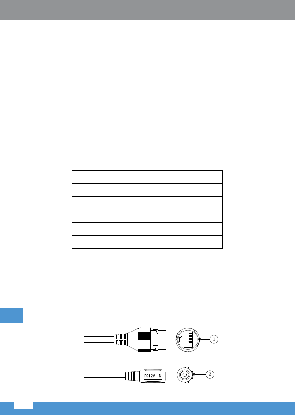
Die folgende Abbildung dient nur als Referenz; sie wird benutzt zur Anzeige
der Kabelstecker-Funktionen. Verschiedene Geräte können verschiedene
Kabel haben.
Abbildung 1-1
SN Anschluss Name Stecker Funktionsbeschreibung
1 LAN Netzwer-
2 DC 12V Stromver-
DE
kanschluss
sorgung
Ethernet
Stecker
- Stromanschluss. DC 12V
Table 1-2
Verbindung zu einem Standard
Ethernet Kabel.
Hinweis
Kamera benötigt PoE (802.3
af) Stromversorgung.
Eingang.
Warnung
Das Gerät kann beschädigt
werden, wenn die
Versorgungs-Spannung
von der am Typenschild
angegebenen Spannung
abweicht.
6 7
Page 7
1.2 Rahmen und Abmessungen
Hinweis
Die folgende Abbildung dient nur als Referenz; sie wird benutzt zur Anzeige
der Geräteabmessungen.
Abbildung 1-2
2. Geräteinstallation
2.1 Gerätemontage
Hinweis
Die Montageoberäche muss zumindest das 3-fache Gewicht von Halterung
und Kamera tragen.
DE
Page 8
Bedienungsanleitung Bedienungsanleitung
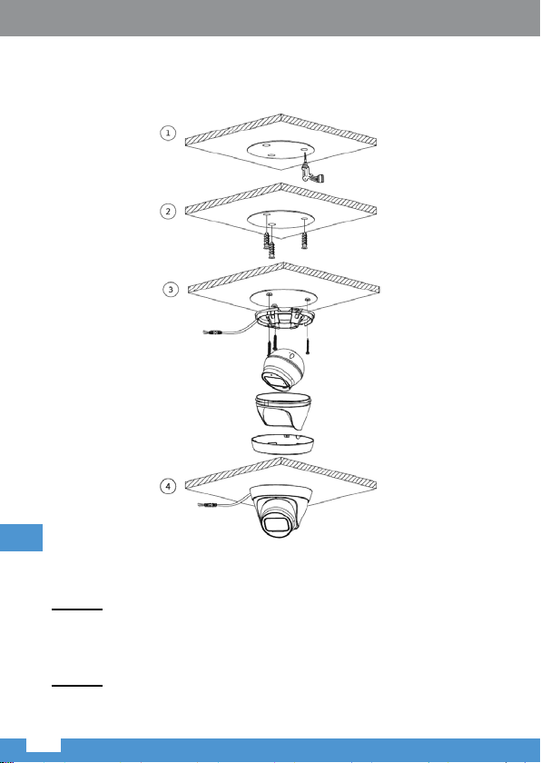
2.1.1 TURM
Montageoberäche
Dübel
Sockel
Schrauben
Kameramodul
Gehäuse
Dekorativer
Abdeckring
Abbildung 2-1
Schritt 1
Drehen Sie den Sockelring im Uhrzeigersinn aus dem Gehäuse und nehmen
diesen heraus.
Schritt 2
DE
Benutzen Sie die beigefügte Schablone um die Dübellöcher zu markieren.
Bohren Sie Löcher in die Montageoberäche, stecken die Dübel hinein und
sichern diese fest.
Schritt 3
Führen Sie das Kabel aus dem Kabelausgangsloch des Gerätes, Sie können
untere oder seitliche Verkablung wählen.
8 9
Page 9
• Verkabelung über die Montageoberäche: Das Kabel wird direkt auf die
Montageoberäche verlegt, wodurch das Kabel eektiver geschützt wird
DE
Abbildung 2-2
Page 10
Bedienungsanleitung Bedienungsanleitung
• Seitliche Verkabelung: Das Kabel wird vom Ausgang des Kameragehäuses
verlegt.
DE
Abbildung 2-3
Schritt 4
Stellen Sie den Gerätesockel auf eine korrekte Position ein und richten
die Schraubenlöcher am Gerätesockel an den Befestigungslöchern der
Dübellöcher aus. Drehen Sie dann die Schrauben in die Dübel und sichern
diese fest.
Schritt 5
Setzen Sie das Kameramodul in ein Gehäuse und legen es in den Sockel, bis
es fest einrastet.
10 11
Page 11
Schritt 6
Setzen Sie den Dekorationsring auf die Kamera (achten Sie auf die
Vertiefungen auf dem Sockel und auf die Wölbungen auf dem Dekorationsring)
und drehen diesen im Uhrzeigersinn in den Sockel. Er ist gut installiert, wenn
Sie ein Klicken hören.
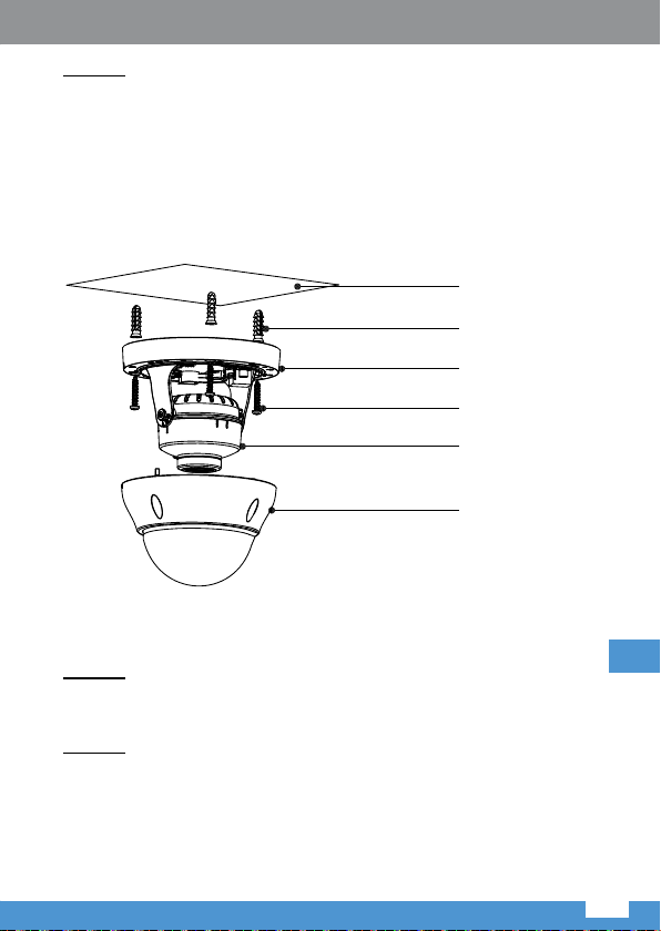
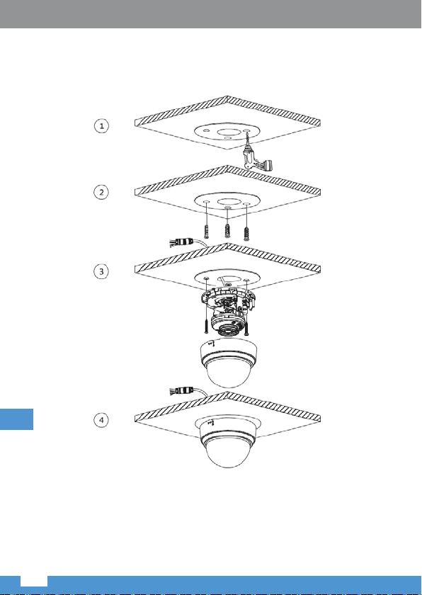
2.1.2 DOM
Montageoberäche
Dübel
Sockel
Schrauben
Kameramodul
Gehäuse
Abbildung 2-4
Schritt 1
Benutzen Sie die beigefügte Schablone um die Dübellöcher zu markieren.
Bohren Sie Löcher in der Montageoberäche, stecken die Dübel hinein und
sichern diese fest.
Schritt 2
Stellen Sie die Position des Montagesockels ein. Führen Sie das Kabel aus
dem Kabelausgangsloch des Gerätes, Sie können untere oder seitliche
Verkablung wählen.
DE
Page 12
Bedienungsanleitung Bedienungsanleitung
• Verkabelung über die Montageoberäche: Das Kabel wird direkt auf die
Montageoberäche verlegt, wodurch das Kabel eektiver geschützt wird.
DE
Abbildung 2-5
12 13
Page 13
• Seitliche Verkabelung: Das Kabel wird vom Ausgang des Kameragehäuses
verlegt.
Abbildung 2-6
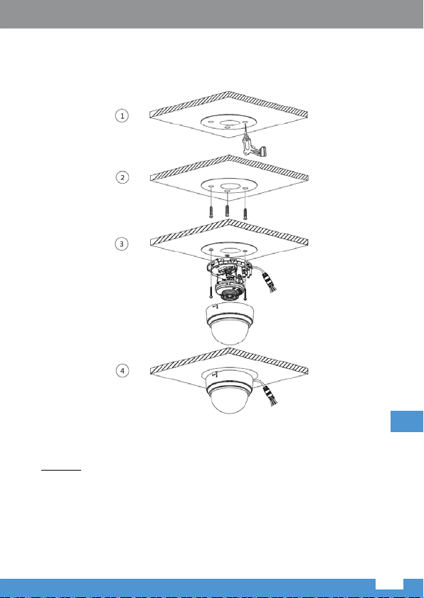
Schritt 3
Richten die Schraubenlöcher am Gerätesockel an den Befestigungslöchern
der Dübellöcher aus. Drehen Sie dann die Schrauben in die Dübel und sichern
diese fest. Danach befestigen Sie das Gehäuse am Gerätesockel und sichern
diese fest.
Hinweis: Das Domgehäuse steht in Zusammenhang mit der WasserschutzFunktion, stellen Sie sicher dass dieser nach dem ausrichten, fest
angeschraubt ist.
DE
Page 14
2.1.3 Installationstyp
Bedienungsanleitung Bedienungsanleitung
DE
Deckenmontage
Abbildung2-7
Wandmontage
Abbildung 2-8
14 15
Page 15
Mastmontage Hängemontage
Abbildung 2-9 Abbildung 2-10
DE
Page 16
Bedienungsanleitung Bedienungsanleitung
Anschließen des Wasserdichten Kabels (Optional)
Wird benutzt zum anschließen des Stromkabels und Netzwerkkabels.
Hinweis
Der wasserdichte Stecker wird benötigt wenn das Gerät solch einen Stecker
besitzt und im Freien benutzt wird.
Die Montage des wasserdichten Steckers wird in Abbildung 2 -11.
DE
Abbildung 2-11
16 17
Page 17
Schritt 1
Ziehen Sie das Netzwerkkabel nacheinander durch die wasserdichte
Befestigungsabdeckung und den wasserdichten Stecker, halten Sie die konvexe
Mutter nach außen und befestigen den Gummiring am Netzwerkanschluss.
Schritt 2
Stecken Sie das Kabel in den Netzwerkanschluss und drehen den wasserdichten
Stecker im Uhrzeigersinn, um ihn fest mit dem Netzwerkanschluss zu
verbinden.
Schritt 3
Legen Sie den Befestigungsgummiring auf das Kabel zwischen der
wasserdichten Befestigungsabdeckung und der wasserdichten Verbindung
und stecken ihn dann in das Hauptgehäuse des wasserdichten Steckvers.
Schritt 4
Bedecken Sie die wasserdichte Befestigungsabdeckung am Hauptkörper des
wasserdichten Steckers. Drehen Sie den wasserdichten Befestigungsdeckel
im Uhrzeigersinn, um ihn fest mit dem Hauptkörper des wasserdichten
Steckers zu verriegeln. Bisher ist die Installation abgeschlossen.
2.2 Einstellen des Gerätewinkels
TURM
DE
Abbildung 2-12
Stellen Sie die Position der Kamera manuell ein.
Hinweis: Einstellungsbereich des Linsenwinkels: horizontale Drehrichtung
(0~360°), vertikale Drehrichtung (0~90°), Bilddrehrichtung (0~+360°).
Page 18

Bedienungsanleitung Bedienungsanleitung
DOME
Abbildung 2-13
• Halten Sie die Halterung an beiden Seiten des Kameramoduls und drehen
dieses horizontal.
• Halten Sie das Kameramodul und drehen es um seine Achse, um das
Objektiv auf den richtigen Überwachungswinkel einzustellen.
• Lösen Sie die Schrauben an den Seiten der Halterung mit einem
Schraubendreher, halten das Kameramodul und richten es vertikal aus.
Hinweis: Einstellungsbereich des Linsenwinkels: vertikal (0~+75°), horizontal
(0~+355°), Bilddrehrichtung (0~+355°).
3. Netzwerkkonguration
Sie können das Gerät initialisieren und die IP-Adresse über die WEB
Benutzeroberäche ändern. Weitere Informationen nden Sie in der WEB
Bedienungsanleitung auf der CD.
DE
Hinweis
• Die Initialisierung muss implementiert werden, wenn das Gerät zum ersten
Mal verwendet wird oder das Gerät auf die Werkseinstellungen zurückgesetzt
wurde.
• Sie können die Initialisierung nur implementieren, wenn sich die IP-Adresse
des Geräts (standardmäßig 192.168.1.108) und die IP-Adresse des PCs im
selben Netzwerksegment benden.
• Die folgenden Abbildungszwecke dienen nur als Referenz; unterschiedliche
Modelle können unterschiedliche Benutzeroberächen haben.
18 19
Page 19
3.1 Anmelden in der WEB Benutzeroberäche
Step 1
Open IE browser, enter the camera IP address into the address bar and then
press Enter button. Please operate according to the interface prompt if the
interface displays guide of Software License Agreement and Online Upgrade.
IMPORTANT: using internet browsers other than Internet Explorer may result
in limited access to camera’s conguration and usage.
Step 2
Enter username and password, click Login (default login: admin; password:
admin).
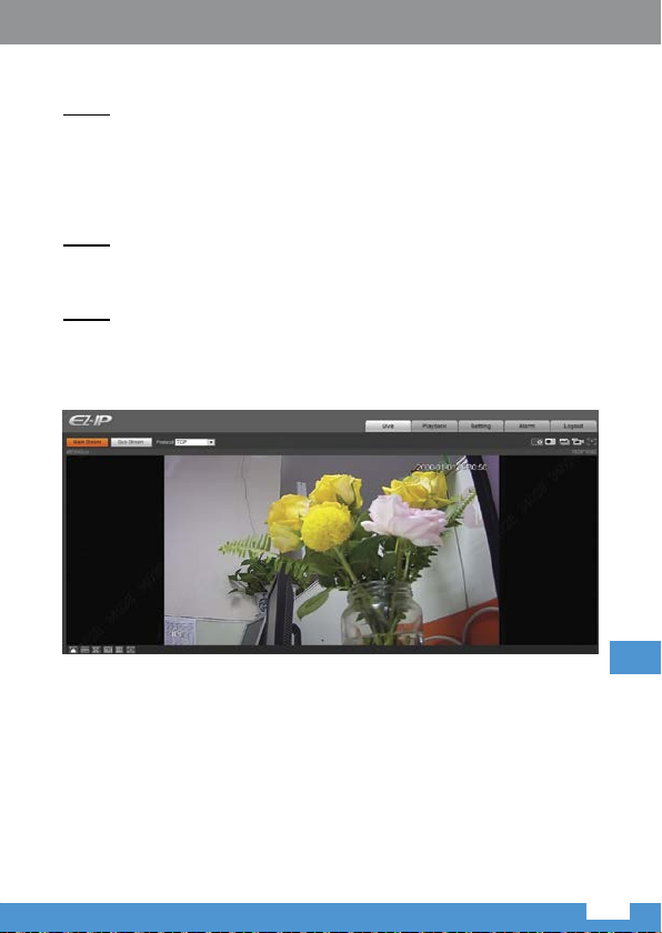
Step 3
For the rst login, click Click Here to Download Plug-in, install controls
according to system prompt. The main interface will be shown in Figure 3 -1
after control installation is completed.
Figure 3-1
DE
Page 20
Bedienungsanleitung Bedienungsanleitung
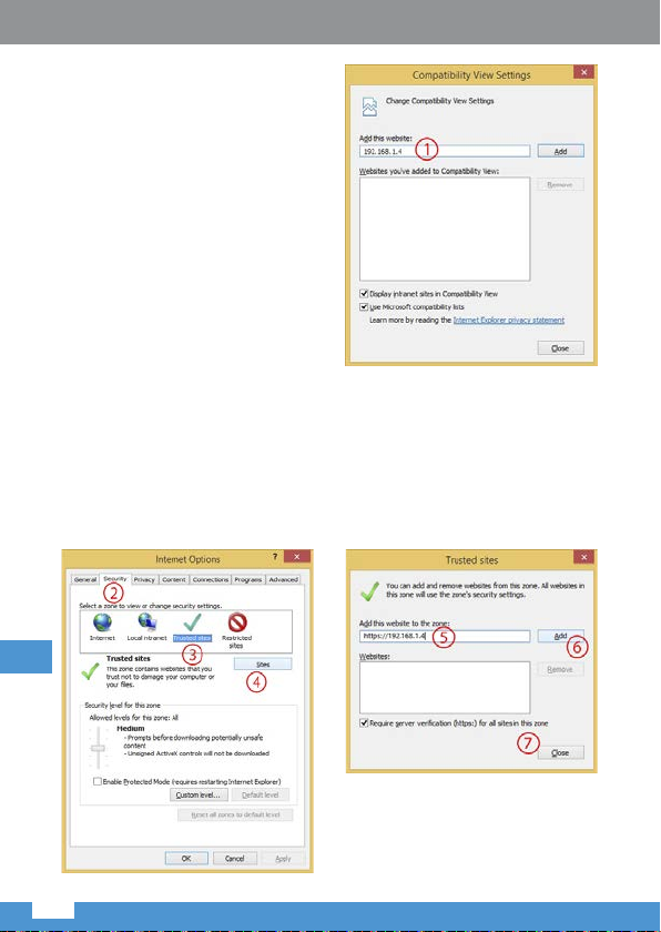
Bei Problemen mit der PlugIn Installation, befolgen Sie die
unteren Schritte:
1. Önen Sie den Internet
Explorer Browser, gehen zu
“Werkzeuge (Extras)” (Links
ALT + X) > “Einstellungen
der Kompatibilitäts-Ansicht
ändern” und fügen die IP
Adresse der IP Kamera hinzu;
Klick “Hinzufügen” danach
“Schließen”.
2. Gehen Sie erneut zu “Werkzeuge (Extras)” (Links ALT + X) > “Internet
Optionen” > “Sicherheit” > “Vertrauenswürdige Sites” > “Sites”. Geben
Sie die IP Adresse der IP Kamera in das Feld “Diese Webseite zur Zone
hinzufügen” ein. Stellen Sie sicher dass “Für Sites dieser Zone ist eine
Server-Überprüfung (https:) erforderlich” nicht ausgewählt ist. Drücken Sie
“Hinzufügen” danach “Schließen” um die Änderungen zu bestätigen und
das Menü zu verlassen.
DE
20 21
Page 21
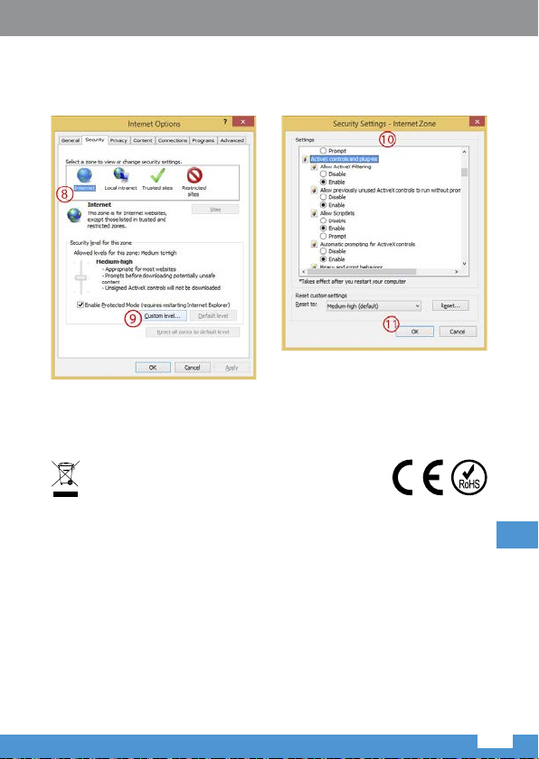
3. Nächstens gehen Sie zu “Internet” > “Stufe anpassen” and aktivieren die
Optionen in “ActiveX Steuerelemente und Plug-Ins” (Siehe Abbildung unten
– Punkt 10).Drücken Sie zweimal OK zum bestätigen.
4. Internet Explorer Browser neu starten. Sobald die Einstellungen beendet sind,
geben Sie die IP Adresse der IP Kamera in die Adressleiste ein und fahren
mit der automatischen Installation der Plug-Ins fort, gemäß den Richtlinien.
Deutsch
Korrekte Entsorgung dieses Produkts
(Elektromüll)
(Anzuwenden in den Ländern der Europäischen Union und anderen europäischen
Ländern mit einem separaten Sammelsystem)
Die Kennzeichnung auf dem Produkt bzw. auf der dazugehörigen Literatur gibt an, dass
es nach seiner Lebensdauer nicht zusammen mit dam normalem Haushaltsmüll entsorgt
werden darf. Entsorgen Sie dieses Gerät bitte getrennt von anderen Abfällen, um der
Umwelt bzw. der menschlichen Gesundheit nicht durch unkontrollierte Müllbeseitigung zu
schaden. Recyceln Sie das Gerät, um die nachhaltige Wiederverwertung von stoichen
Ressourcen zu förder n. Private Nutzer sollten den Händler, bei dem das Produkt gekauft
wurde, oder die zuständigen Behörden kontaktieren, um in Erfahrung zu bringen, wie
sie das Gerät auf umweltfreundliche Weise recyceln können. Gewerbliche Nutzer
sollten sich an Ihren Lieferanten wenden und die Bedingungen des Verkaufsvertrags
konsultieren. Dieses Produkt darf nicht zusammen mit anderem Gewerbemüll entsorgt
werden.
Hergestellt in China für LECHPOL ELECT RONICS Sp. z o.o. Sp.k.,
ul. Garwolińska 1, 08-400 Miętne.
DE
Page 22

Ovner’s manual
Thank you for purchasing our network cameras.
This user’s manual is designed to be a reference tool for using your product.
Please read the following safeguards and warnings carefully before you use this
series product.
Please keep this user’s manual well for future reference.
Important Safeguards and Warnings
Electrical safety
• All installation and operation should conform to your local electrical safety
codes.
• The power source shall conform to the requirement of the Safety Extra
Low Voltage (SELV) standard, and supply power with rated voltage which
conforms to Limited power Source requirement according IEC60950-1.
Please note that the power supply requirement is subject to the device label.
• Make sure the power supply is correct before operating the device.
• Prevent the power cable from being trampled or pressed, especially the plug,
power socket and the junction extruded from the device.
• We assume no liability or responsibility for all the res or electrical shock
caused by improper handling or installation.
Environment
• Do not aim the device at strong light to focus, such as lamp light and sun
light, otherwise it might cause over brightness or light marks, which are not
the device malfunction, and aect the longevity of Complementary Metal-
Oxide Semiconductor (CMOS).
• Do not place the device in a damp or dusty environment, extremely hot
or cold temperatures, or the locations with strong electromagnetic radiation
or unstable lighting.
• Keep sound ventilation to avoid heat accumulation.
• Transport, use and store the device within the range of allowed humidity and
temperature.
• Heavy stress, violent vibration or water splash are not allowed during
transportation, storage and installation.
EN
• Pack the device with standard factory packaging or the equivalent material
when transporting the device.
Operation and Daily Maintenance
• Do not dismantle the device because there is no component that can be xed
by users themselves. Otherwise, it might cause water leakage or bad image
due to unprofessional dismantling.
• If there’s humidity or fog present on the internal components of the camera,
22
Page 23

Ovner’s manual
contact an authorized service point.
• It is recommended to use the device together with lightning arrester
to improve lightning protection eect.
• Use the soft, slightly damp cloth to clean the device. If the dust is dicult
to be removed, please wipe it away with a clean cloth wetted slightly
by the mild detergent, and then use the dry cloth to clean the device. Do not
use volatile solvents like alcohol, benzene, thinner, or strong detergent with
abrasiveness, otherwise it will damage the surface coating.
• We are not liable for any problems caused by unauthorized modication
or attempted repair.
• You can use air gun to remove the dust if the cover is stained with dust.
• This appliance may be used by children who are above 8 years old and
by persons with reduced physical, sensory or mental capabilities, or lack
of experience and knowledge, if they are supervised and guided by a person
who is responsible for their safety in a cautious manner, and all the safety
precautions are understood and followed. Children should not play with this
device. Children should not perform cleaning and servicing of the device
unsupervised.
Warnings
• Please protect the device from unauthorized access with strong passwords
and upgrading rmware to the latest version.
• Please modify the default password after login to avoid being stolen.
• Use the standard components provided by manufacturer and make sure the
device is installed and xed by professional engineers.
• The surface of the image sensor should not be exposed to laser beam
radiation in an environment where a laser beam device is used.
• Do not provide two or more power supply sources for the device
simultaneously; otherwise it might damage the device (power mains supply
and PoE simultaneously).
Disclaimer
• This manual is for reference only. Please refer to the actual product for more
details.
• Producer does not claim liability for any damages caused by inappropriate
use of the device disregarding user manual.
• Minor dierences might be found in user interface, and there might
be deviation between the actual value of some data and the value provided
in the manual due to the reasons such as the real environment is not stable.
Please refer to the nal explanation of the company if there is any doubt or
dispute.
• All the designs and software are subject to change without prior written
notice. The manual will be regularly updated according to the product
EN
23
Page 24
Ovner’s manual
upgrade without prior announcement.
• Please contact the supplier or customer service if there is any problem
occurred when using the device.
• Please contact the customer service for the latest procedure and
supplementary documentation.
• Please visit www.lechpol.com website or contact your local service engineer
for more information.
• The company is not liable for any loss caused by the operation that does not
comply with the manual.
• If there is any uncertainty or controversy, please refer to our nal explanation.
Note
• Please refer to the disk for more details.
• Before installation, please open the package and check all the components
are included. Contact your local retailer as soon as possible if something
is broken in your package.
Accessory Name Amount
Network Camera Unit 1
Quick Start Guide 1
Waterproof Connector 1
Screw Package 1
CD 1
Table 1-1
1. Framework
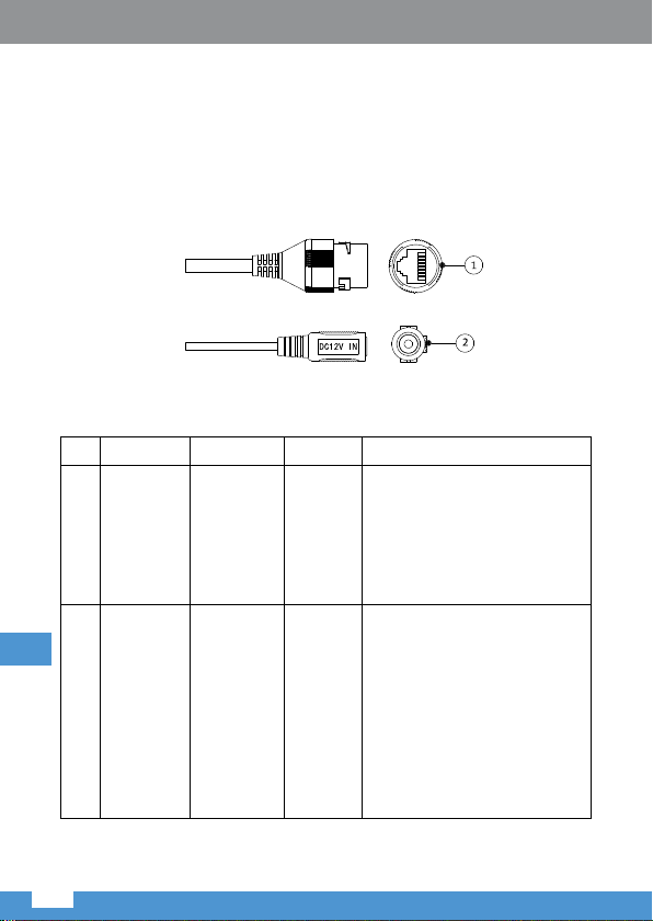
1.1 Device External Cable
Note
The following gure is for reference only; it is used to know the function of cable
port. Dierent devices may have dierent cable.
EN
Figure 1-1
24
Page 25

Ovner’s manual
SN Port Port name Connector Function description
1 LAN Network port Ethernet
2 DC 12V Power input
port
port
- Power port. Input DC 12V.
Table 1-2
Connect to standard Ethernet
cable.
Note
Camera requires PoE (802.3
af) power supply.
Caution
It may cause damage to the
device if it fails to power the
device according to the label
description.
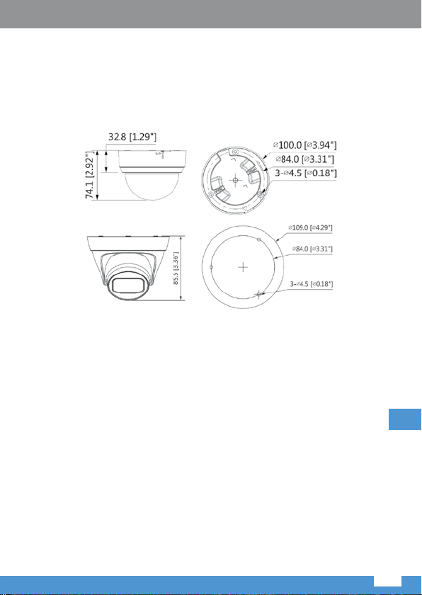
1.2 Framework and Dimension
Note
The following gures are for reference only, which are used to know the device
dimension.
Figure 1-2
EN
25
Page 26

Ovner’s manual
2. Device Installation
2.1 Fix Device
Note
The mounting surface needs to sustain at least 3x weight of the bracket and
camera.
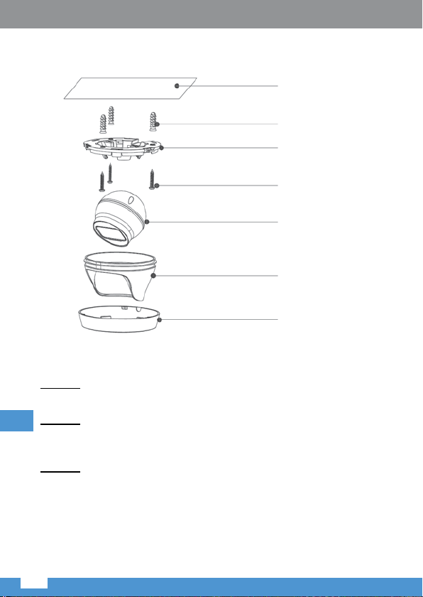
2.1.1 TURRET
Mounting surface
Expansion bolt
Pedestal
Screw
Camera
module
Enclosure
Decoration
cover ring
Figure 2-1
EN
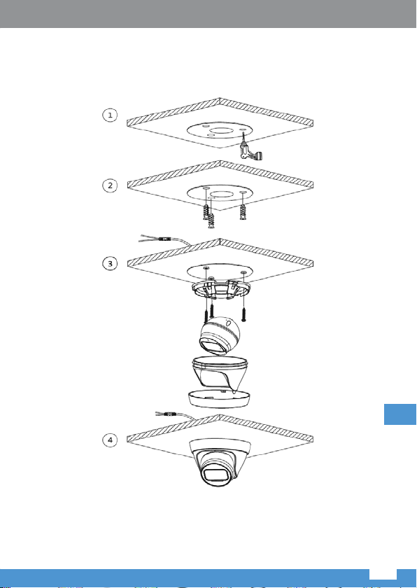
Step 1
Turn the pedestal ring clockwise out of the button placement and take it out.
Step 2
Use the attached position map and mark the spots for the expansion bolts. Drill
holes on the mounting surface and then insert expansion bolts into the holes,
secure them rmly.
Step 3
Lead the cable out from the cable exit hole of the device, you can select bottom
cabling or side cabling.
26
Page 27

Ovner’s manual
• Mounting surface cabling: It is to lead out cable from mounting surface
directly, which can eectively protect cable.
Figure 2-2
EN
27
Page 28

• Side cabling: It is to lead out cable from housing of the camera.
Ovner’s manual
EN
Figure 2-3
Step 4
Adjust the device pedestal to a proper position and line up the screw holes on
the device pedestal to the xing holes of expansion bolt holes, and then twist
the screws into the expansion bolts and x them rmly.
Step 5
Place the camera module into an enclosure and put it into the pedestal until
it is rmly locked with the latches.
28
Page 29

Ovner’s manual
Step 6
Put the decoration cover ring on the camera (pay attention to the indentations
on the pedestal and bulges on the decoration cover ring) and rotate it clockwise
into the pedestal, it is well installed when you hear the “click” sound.
2.1.2 Dome
Mounting surface
Expansion bolt
Pedestal
Screw
Camera module
Enclosure
Figure 2-4
Step 1
Use the attached position map and mark the spots for the expansion bolts. Drill
holes on the mounting surface and then insert expansion bolts into the holes,
secure them rmly.
Step 2
Adjust the location of the mounting pedestal. Lead the cable out from the cable
exit hole of the device, you can select bottom cabling or side cabling.
EN
29
Page 30

Ovner’s manual
• Mounting surface cabling: It is to lead out cable from mounting surface
directly, which can eectively protect cable.
EN
Figure 2-5
30
Page 31

Ovner’s manual
• Side cabling: It is to lead out cable from housing of the camera.
Figure 2-6
Step 3
Align the screw hole on the pedestal with the mounting hole on the mounting
surface, and then twist the screws into the expansion bolts and lock them
rmly. Finally x the enclosure on the pedestal and screw it rmly.
Note: Dome enclosure is related to waterproof function, make sure it is rmly
tightened after adjustment.
EN
31
Page 32

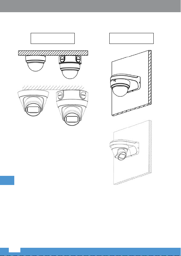
2.1.3 Installation Type
Ovner’s manual
EN
Ceiling-mounted
Figure 2-7
Wall-mounted
Figure 2-8
32
Page 33

Ovner’s manual
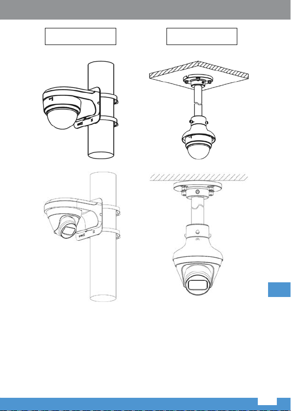
Pole-mounted Hang-mounted
Figure 2-9 Figure 2-10
EN
33
Page 34

Ovner’s manual
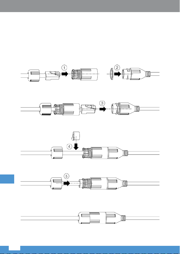
Connect Waterproof Cable (optional)
It is to connect device power cable and network cable.
Note
It needs to install waterproof connector when the device is equipped with
waterproof connector and it is used outdoors.
The installation of waterproof connector is shown in gure 2-11
EN
Figure 2-11
34
Page 35

Ovner’s manual
Step 1
Pull the network cable through waterproof fastening cover and waterproof
connector successively, keep the convex groove outward and install the rubber
ring onto the network port.
Step 2
Insert the cable into the network port, rotate the waterproof connector clockwise
to make it rmly locked with network port.
Step 3
Lay the fastening rubber ring onto the cable between waterproof fastening
cover and waterproof connection, and then stu it into the main body
of waterproof connector.
Step 4
Cover the waterproof fastening cover on the main body of waterproof connector,
rotate the waterproof fastening cover clockwise to make it rmly locked with
main body of waterproof connector. So far, the installation has been completed.
2.2 Adjust Device Angle
TURRET
Figure 2-12
Adjust the position of the camera manually.
Note: The range of angle adjustment for lens: horizontal rotation direction
(0~360°), vertical rotation direction (0~90°), image rotation direction (0~+360°).
EN
35
Page 36

Ovner’s manual
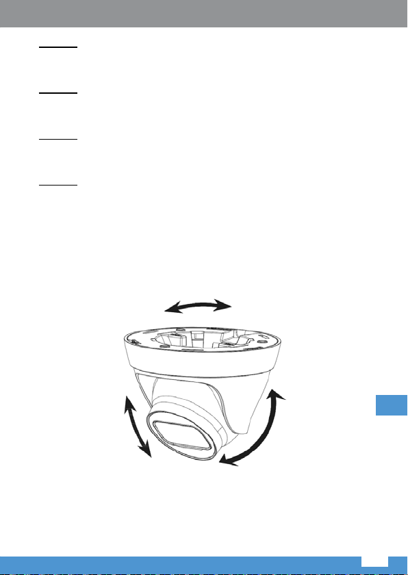
DOME
Figure 2-13
• Hold the bracket on both sides of the camera module, and rotate it
horizontally.
• Hold the camera module and rotate it around its axis to adjust the lens image
to proper monitoring angle.
• Use a screwdriver to loosen the screws at the sides of the bracket, and hold
the camera module and adjust it vertically.
Note: Range of adjusting lens angle: vertical (0~+75°), horizontal (0~+355°),
image rotation direction (0~+355°).
3. Network Conguration
You can initialize the device and modify IP address via WEB interface. Please
refer to the WEB Operation Manual in the disk for more details.
Note
• It needs to implement initialization if it is the rst time use device or the device
EN
is restored to factory default.
• It can implement initialization only when the device IP address (192.168.1.108
by default) and the IP address of PC are in the same network segment.
• The following gures are for reference only; dierent models may have
dierent interfaces.
36
Page 37

Ovner’s manual
3.1 Login WEB Interface
Step 1
Open IE browser, enter the camera IP address into the address bar and then
press Enter button. Please operate according to the interface prompt if the
interface displays guide of Software License Agreement and Online Upgrade.
IMPORTANT: using internet browsers other than Internet Explorer may result
in limited access to camera’s conguration and usage.
Step 2
Enter username and password, click Login (default login: admin; password:
admin).
Step 3
For the rst login, click Click Here to Download Plug-in, install controls
according to system prompt. The main interface will be shown in Figure 3 -1
after control installation is completed.
Figure3-1
EN
37
Page 38

Ovner’s manual
In case of troubles with plug-in
installation, follow below steps:
1. Open the Internet Explorer browser,
go to “Tools” (left ALT + X) >
“Compatibility view settings” and
add camera’s IP address; click
“Add” then “Close”.
2. Go to “Tools” (left ALT + X) again > “Internet options” > “Security” > “Trusted
sites” > “Sites”. Input camera’s IP address into “Add this website to the zone”
space. Make sure the “Require server verication (https:) for all sites in this
zone” is unchecked. Press “Add”, then “Close” to approve changes and exit.
EN
38
Page 39

Ovner’s manual
3. Next, go to “Internet” > “Custom level” and enable options in “ActiveX
controls and plug-ins” (as shown below - see point 10). Then press OK twice
to conrm.
4. Restart the Internet Explorer browser. Once the settings adjustment is
nished, input camera’s IP address into web browser address bar and
complete automatic installation of plug-ins according to guidelines.
English
Correct Disposal of This Prod uct
(Was te Electr ical & Electronic Equipment)
(Appli cable in the Euro pean Union and ot her European countries with s eparate colle ction
systems) This marking show n on the product or its literature, indicates that it should
not be disposed with other household wastes at the end of its working life. To prevent
possible harm to the environment or human health from uncontrolled waste disposal,
please separate this from other types of wastes and recycle it responsibly to promote
the sustainable reuse of material resources. Household users should contact either the
retailer where they purchased this product, or their local government oce, for details
of where and how they can take this item for environmentally safe recycling. Business
users should contact their supplier and check the terms and conditions of the purchase
contract. This product should not be mixed with other commercial wastes for disposal.
Made in China for LECHPOL ELECTRONICS Sp. z o.o. Sp.k.,
ul. Garwolińska 1, 08-400 Miętne.
EN
39
Page 40

Instrukcja obsługi
Instrukcja obsługi Instrukcja obsługi
Dziękujemy za zakup tego urządzenia.
Instrukcja obsługi służy, jako przewodnik przy obsłudze zakupionego przez
Państwo urządzenia.
Przed użyciem należy dokładnie zapoznać się z treścią instrukcji obsługi,
zawartymi w niej ostrzeżeniami i wskazówkami oraz zachować ją w celu
późniejszego wykorzystania.
Ważne kwestie bezpieczeństwa i ostrzeżenia
Bezpieczeństwo elektryczne
• Instalacja i obsługa powinny obywać się zgodnie z regulacjami dotyczącymi
bezpieczeństwa obowiązującymi w danym rejonie.
• Źródło zasilania powinno być zgodne ze standardem SELV (Safety Extra-Low
Voltage - obwód o napięciu znamionowym bardzo niskim) i zasilać napięciem
zgodnym z wymaganiami IEC60950-1. Należy zauważyć, że wymagania
dotyczące zasilania urządzenia wskazane są na etykiecie urządzenia.
• Przed podłączeniem do źródła zasilania, należy sprawdzić zgodność
parametrów zasilania wymaganego przez kamerę i dostarczanego z gniazda
sieciowego/urządzenia PoE.
• Przewód zasilania powinien być tak umieszczony, aby nie uległ uszkodzeniu
w przypadku nadepnięcia lub przygniecenia przez inne przedmioty. Należy
zwrócić szczególną uwagę na miejsca połączeń, wtyczki oraz miejsce
wyjścia przewodu z urządzenia.
• Producent nie ponosi odpowiedzialności za obrażenia/szkody powstałe
w skutek nieprawidłowego użycia / obsługi / montażu tego urządzenia.
Środowisko pracy
• Nie należy kierować urządzenia na źródło silnego światła, jak światło
słoneczne czy bezpośrednie źródło sztucznego światła, gdyż może to
spowodować np. efekt ary czy efekt prześwietlenia, co nie jest wadą
urządzenia, ale wpływa na żywotność matrycy CMOS.
• Nie należy umieszczać urządzenia w wilgotnym lub wysoce zakurzonym
środowisku. Nie należy używać i przechowywać urządzenia w miejscach
o ekstremalnych temperaturach, silnym polu magnetycznym czy niestabilnym
oświetleniu.
• Należy zachować poprawną wentylację urządzenia, aby nie dopuścić do
PL
nadmiernego przegrzania.
• Należy pamiętać, aby warunki podczas transportu, użytkowania
i przechowywania urządzenia zawierały się w zakresach dopuszczalnej
wilgotności i temperatury.
• Silny nacisk, mocne wstrząsy lub zachlapanie urządzenia płynami są
zabronione podczas transportu, przechowywania i instalacji.
• Podczas transportu, urządzenie należy zapakować w oryginalne pudełko.
40
Page 41

Obsługa i codzienna konserwacja
• Urządzenie nie posiada części, które mogłyby być poddane naprawie
przez użytkownika. Nie należy samodzielnie demontować urządzenia.
W przeciwnym wypadku może dojść do zalania lub skutkować niską jakością
obrazu ze względu na niewłaściwy demontaż.
• Jeśli wewnątrz kamery pojawi się wilgoć, należy skontaktować się
z autoryzowanym punktem serwisowym.
• Zaleca się użycia ogranicznika przepięć, aby zwiększyć ochronę odgromową.
• Do czyszczenia obudowy należy używać miękkiej, lekko wilgotnej
ściereczki. W przypadku uporczywych zabrudzeń, należ użyć czystej
ściereczki zwilżonej w delikatnym detergencie, a następnie przetrzeć suchą
ściereczką. Nie należy używać rozpuszczalników w aerozolu ani silnych
detergentów ściernych, gdyż może to doprowadzić do uszkodzenia powłoki
powierzchniowej.
• Producent ani dystrybutor nie ponoszą odpowiedzialności za jakiekolwiek
straty powstałe w skutek zmian lub napraw przeprowadzanych przez
użytkownika.
• Kurz znajdujący się na urządzeniu można usunąć za pomocą sprężonego
powietrza.
• Niniejszy sprzęt może być użytkowany przez dzieci w wieku co najmniej
8 lat i przez osoby o obniżonych możliwościach zycznych, czuciowych
lub umysłowych, a także te, które nie posiadają doświadczenia i nie są
zaznajomione ze sprzętem, jeżeli zapewniony zostanie nadzór lub instruktaż
odnośnie użytkowania sprzętu w bezpieczny sposób, tak aby związane z tym
zagrożenia były zrozumiałe. Należy poinstruować dzieci, aby nie traktowały
urządzenia jako zabawki. Dzieci nie powinny wykonywać czyszczenia
i konserwacji sprzętu bez nadzoru.
Uwaga!
• Należy zabezpieczyć urządzenie przed dostępem osób niepowołanych
poprzez stosowanie silnych haseł oraz aktualizację oprogramowania do
najnowszej wersji.
• Zaleca się zmianę domyślnego hasła po zalogowaniu się w celu zwiększenia
bezpieczeństwa.
• Należy używać oryginalnych komponentów lub akcesoriów dostarczonych
przez producenta i upewnić się, że urządzenie zostanie zainstalowane
i konserwowane przez wykwalikowaną osobę.
• Powierzchnia sensora obrazu nie powinna być wystawiona na
promieniowanie laserowe.
• Nie należy podłączać urządzenia jednocześnie do dwóch lub więcej źródeł
zasilania, gdyż może to prowadzić do uszkodzenia urządzenia (zasilanie
12 V DC i PoE jednocześnie).
PL
41
Page 42

Instrukcja obsługi Instrukcja obsługi
Uwaga
• Instrukcja służy wyłącznie w celach referencyjnych. Obowiązujący jest stan
faktyczny urządzenia.
• Producent nie ponosi odpowiedzialności za szkody powstałe w wyniku
nieprawidłowego użycia urządzenia niezgodnego z instrukcją obsługi.
• Producent zastrzega możliwość rozbieżności pomiędzy interfejsem
użytkownika a informacjami podanymi w instrukcji obsługi. W przypadku
wątpliwości, należy odnieść się do wyjaśnienia producenta.
• Oprogramowanie oraz konstrukcja produktu mogą ulec zmianie bez
wcześniejszego pisemnego powiadomienia. Instrukcja będzie aktualizowana
regularnie zgodnie z aktualizacjami produktu. Zmiany w instrukcji będą
wprowadzane bez uprzedniego powiadomienia.
• Należy się skontaktować z dostawcą lub obsługą klienta w przypadku
jakichkolwiek problemów podczas obsługi urządzenia.
• Należy się skontaktować z obsługą klienta w celu uzyskania informacji na
temat najnowszych zaleceń i dodatkowej dokumentacji.
• Należy odwiedzić stronę internetową www.lechpol.eu lub skontaktować
się z centrum serwisowym, aby uzyskać więcej informacji.
• Producent nie ponosi odpowiedzialności za jakiekolwiek straty wynikłe
z powodu niezastosowania się do instrukcji.
• W przypadku wątpliwości, należy odnieść się do wyjaśnienia producenta.
Wskazówka
• Więcej szczegółów znajduje się na dysku załączonym w zestawie.
• Przed instalacją, należy sprawdzić czy wszystkie elementy znajdują się
w zestawie. W przeciwnym wypadku, należy się skonsultować ze
sprzedawcą.
Akcesorium Ilość
Kamera 1
Skrócona instrukcja obsługi 1
Wodoszczelna złączka 1
Paczka wkrętów montażowych 1
PL
CD 1
Tabela 1-1
42
Page 43

1. Wstęp
1.1 Przewody
Wskazówka
Poniższa ilustracja ma charakter poglądowy. Poszczególne urządzenia mogą
mieć inne przewody.
Rys. 1-1
Lp. Port Nazwa portu Złącze Funkcja
1 LAN Port sieciowy Port
2 DC 12V Gniazdo
zasilania
Ethernet
- Gniazdo zasilania. Wejście:
Należy podłączyć kabel
Ethernet.
Wskazówka
Kamera wymaga zasilania
PoE (802.3 af)
12 V DC
Uwaga
W przypadku podłączenia
zasilania niezgodnego z
wymaganiami urządzenia,
urządzenie może zostać
uszkodzone.
PL
Tabela 1-2
43
Page 44

1.2 Wymiary
Wskazówka
Ilustracja i podane wymiary mają jedynie charakter poglądowy.
Rys. 1-2
Instrukcja obsługi Instrukcja obsługi
PL
44
Page 45

2. Montaż urządzenia
2.1 Montaż urządzenia
Wskazówka
Powierzchnia montażowa musi utrzymać co najmniej 3-krotność wagi uchwytu
i kamery.
2.1.1 Kamera kopułkowa (turret)
Powierzchnia
montażowa
Kołek
rozporowy
Podstawa
Wkręty
Kamera
Obudowa
Pierścień
obudowy
Rys. 2-1
Krok 1
Należy przekręcić wewnętrzną część podstawy zgodnie z ruchem wskazówek
zegara i ją wyjąć.
Krok 2
Przy pomocy załączonego do zestawu szablonu, należy zaznaczyć miejsca,
w których mają być umieszczone kołki rozporowe. Wywiercić otwory
a następnie umieścić w nich kołki rozporowe.
Krok 3
Przeprowadzić przewód z urządzenia (dołem lub bokiem).
PL
45
Page 46

Instrukcja obsługi Instrukcja obsługi
• Przeprowadzenie przewodów dołem: wyprowadzenie z powierzchni
montażowej.
PL
Rys. 2-2
46
Page 47

• Przeprowadzenie bokiem: należy przeprowadzić przewód przez obudowę
boczną kamery.
Rys. 2-3
Krok 4
Należy umieścić podstawę tak, aby otwory w podstawie znajdowały się pod
kołkami rozporowymi umieszczonymi w otworach w powierzchni montażowej,
a następnie przykręcić wkręty.
Krok 5
Umieścić kamerę w obudowie. Wsunąć obudowę do podstawy, aż do
poprawnego zatrzaśnięcia.
PL
47
Page 48

Instrukcja obsługi Instrukcja obsługi
Krok 6
Założyć pierścień obudowy na kamerę (należy zwrócić uwagę na wgłębienia
w podstawie i wypustki na pierścieniu) a następnie wkręcić zgodnie z ruchem
wskazówek zegara w podstawę. Odgłos zatrzaśnięcia oznacza poprawny
montaż.
2.1.2 Kamera kopułkowa (dome)
Powierzchnia
montażowa
Kołek rozporowy
Podstawa
Wkręty
Kamera
Obudowa
Rys. 2-4
Krok 1
Przy pomocy załączonego do zestawu szablonu, należy zaznaczyć miejsca,
w których mają być umieszczone kołki rozporowe. Wywiercić otwory
a następnie umieścić w nich kołki rozporowe.
Krok 2
Przeprowadzić przewód z urządzenia (dołem lub bokiem).
PL
48
Page 49

• Przeprowadzenie przewodów dołem: wyprowadzenie z powierzchni
montażowej.
Rys. 2-5
PL
49
Page 50

Instrukcja obsługi Instrukcja obsługi
• Przeprowadzenie bokiem: należy przeprowadzić przewód przez obudowę
boczną kamery.
Rys. 2-6
Krok 3
Należy umieścić podstawę tak, aby otwory w podstawie znajdowały się pod
PL
kołkami rozporowymi umieszczonymi w otworach w powierzchni montażowej,
a następnie wkręcić wkręty w kołki. Założyć obudowę na podstawę i przykręcić.
Uwaga: wodoszczelność kamery jest bezpośrednio uzależniona od
poprawnego montażu obudowy kopułki kamery.
50
Page 51

2.1.3 Sposoby instalacji
do sutu
Rys. 2-7
do ściany
Rys. 2-8
PL
51
Page 52

Instrukcja obsługi Instrukcja obsługi
na słupie na wysięgniku
PL
Rys. 2-9
Rys. 2-10
52
Page 53

Podłączanie wodoodpornej złączki (opcjonalne)
Podłączenie przewodów zasilających i przewodu sieciowego.
Wskazówka
W przypadku używania urządzenia na zewnątrz, należy zamontować
wodoodporną złączkę.
Schemat montażu wodoodpornej złączki przedstawiony jest na rys. 2-11
Rys. 2-11
PL
53
Page 54

Instrukcja obsługi Instrukcja obsługi
Krok 1
Należy przeciągnąć kabel sieciowy przez osłonę wodoodpornej złączki
a nastepnie przez złączkę. Wypustka musi znajdować się na górze. Po czym
należy zainstalować gumowy pierścień na port sieciowy.
Krok 2
Podłączyć przewód do portu sieciowego, obrócić złączkę wodoodporną
zgodnie z ruchem wskazówek zegara, w celu pewnego zamocowania.
Krok 3
Należy umieścić gumowy pierścień na przewodzie pomiędzy osłoną
wodoodpornej złączki a złączką, a następnie umieścić ten pierścień wewnątrz
złączki.
Krok 4
Założyć osłonę na złączce a następnie obrócić ją zgodnie z ruchem wskazówek
zegara. Instalacja jest zakończona.
2.2 Regulacja kąta nachylenia
KAMERA KOPUŁKOWA (TURRET)
PL
Należy ręcznie dostosować pozycję kamery.
Uwaga: zakres regulacji nachylenia obiektywu: poziomy (0~360°), pionowy
(0~90°), kąt obrotu obiektywu (0~+360°).
54
Rys. 2-12
Page 55

KAMERA KOPUŁKOWA (DOME)
Rys. 2-13
Przed regulacją ustawienia kamery, należy zdemontować obudowę.
• Aby zmienić ustawienie w poziomie, należy chwycić za ramki po obydwu
stron kamery i obrócić.
• Aby zmienić kąt obiektywu, należy chwycić za kamerę i obrócić wokół jej osi.
• Aby zmienić kąt nachylenia kamery, należy za pomocą śrubokrętu poluzować
wkręty ramki po obydwu stronach kamery. Następnie chwycić za kamerę
i zmienić jej kąt nachylenia.
Uwaga: zakres regulacji nachylenia obiektywu: pionowy (0~+75°), poziomy
(0~+355°), kąt obrotu obiektywu (0~+355°).
3. Konguracja sieci
Użytkownik może skongurować urządzenie i zmienić adres IP w interfejsie
użytkownika przez przeglądarkę. Więcej informacji dostępnych jest w pełnej
instrukcji obsługi.
Wskazówka
• Należy przeprowadzić kongurację podczas pierwszego uruchamiania lub
po przywróceniu ustawień fabrycznych.
• Konguracja urządzenia jest możliwa tylko, jeśli adres IP urządzenia
(domyślnie 192.168.1.108) i komputera znajdują się w tej samej sieci.
• Przedstawione ilustracje mają jedynie charakter poglądowy; mogą się różnić
w zależności od modeli.
PL
55
Page 56

Instrukcja obsługi Instrukcja obsługi
3.1 Logowanie się do interfejsu użytkownika przez przeglądarkę
Krok 1
Należy otworzyć przeglądarkę Internet Explorer, wpisać adres IP kamery
w pasku adresu i nacisnąć przycisk Enter na klawiaturze. Należy postępować
zgodnie z krokami wyświetlanymi na ekranie.
WAŻNE: Dostęp przez inne przeglądarki niż Internet Explorer może być
ograniczony.
Krok 2
Wprowadzić nazwę użytkownika i hasło, zatwierdzić klikając „Login”
(Zaloguj się); (domyślny login: admin; hasło: admin).
Krok 3
Podczas pierwszego logowania, należy kliknąć „Click Here” (Naciśnij tutaj)
aby pobrać i zainstalować wtyczki zgodnie z instrukcjami. Po zakończeniu
instalacji, pojawi się okno jak na rys. 3-1.
PL
Rys. 3-1
56
Page 57

W przypadku problemów podczas
instalacji wtyczki, należy wykonać
następujące kroki:
1. Należy uruchomić przeglądarkę
Internet Explorer, wybrać opcję
NARZĘDZIA (lewy ALT+X),
następnie kliknąć w Ustawienia
widoku zgodności i wpisać adres
IP kamery, po czym nacisnąć
DODAJ, następnie ZAMKNIJ.
2. Następnie ponownie wybrać opcję NARZĘDZIA (lewy ALT+X), przejść
do Opcje internetowe i wybrać zakładkę Zabezpieczenia gdzie należy
zaznaczyć Zaufane witryny i kliknąć przycisk Witryny. W polu Dodaj tę
witrynę sieci Web do strefy należy wprowadzić adres IP kamery. Następnie
należy upewnić się, że opcja Żądaj werykacji serwera(...) jest odznaczona!
Nacisnąć przycisk DODAJ. Przyciskiem ZAMKNIJ potwierdzamy wszystko
co do tej pory zostało ustawione i zamykamy okno Zaufane witryny.
PL
57
Page 58

Instrukcja obsługi Instrukcja obsługi
Manual de utilizare
3. W zakładce ZABEZPIECZENIA, przechodzimy do opcji Internet i wybieramy
Poziom niestandardowy. W grupie Kontrolki ActiveX i wtyczki zaznaczamy
opcje (jak na ilustracji poniżej– punkt 10) po czym należy zatwierdzić
przyciskiem OK w oknie Ustawienia zabezpieczeń i ponownie OK w oknie
OPCJE INTERNETOWE.
4. Następnie zrestartować przeglądarkę Internet Explorer. Po zakończeniu
wprowadzania ustawień, należy wpisać adres IP w pole adresu przeglądarki
i dokończyć automatyczną instalację wtyczek zgodnie ze wskazówkami.
Poland
Prawidłowe usuwanie produktu
(zużyty sprzęt elektr yczny i elek troniczny)
Oznaczenie umieszczone na produkcie lub w odnoszących się do niego tekstach
wskazuje, że po upływie okresu użytkowania nie należy usuwać z innymi odpadami
pochodzącymi z gospodarstw domowych. Aby uniknąć szkodliwego wpł ywu na
środowisko naturalne i zdrowie ludzi wskutek niekontrolowanego usuwania odpadów,
prosimy o oddzielenie produktu od innego typu odpadów oraz odpowiedzialny recykling
w celu promowania ponownego użycia zasobów materialnych jako stałej praktyki. W celu
uzyskania informacji na temat miejsca i sposobu bezpiecznego dla środowiska recyklingu
PL
tego produktu użytkownicy w gospodarstwach domowych powinni skontaktować się
z punktem sprzedaży detalicznej, w któr ym dokonali zakupu produktu, lub z organem
władz lokalnych. Użytkownicy w rmach powinni skontaktować się ze swoim dostawcą
i sprawdzić warunki umowy zakupu. Produktu nie należy usuwać razem z innymi
odpadami komercyjnymi.
Wyprodukowano w CHRL dla LECHPOL ELECTRONICS Sp. z o.o.Sp.k.,
ul. Garwolińska 1, 08-400 Miętne.
58
58
Page 59

Vă mulțumim pentru achiziționarea camerelor noastre de supraveghere.
Acest manual de utilizare este conceput pentru a un instrument de referință
pentru utilizarea produsului.
Vă rugîm să citiți cu atenție aceste avertismente și precauții înainte de utilizarea
acestui produs.
Păstrați acest manual de utilizare pentru consultări ulterioare.
Garanții și avertismente importante
Siguranța electrică
• Toate instalațiile și opoerațiunile trebuie să respecte reglementările locale
privind securitatea electrică.
• Sursa de alimentare trebuie să e în conformitate cu standardul SELV (
Safety Extra Low Voltage), și să e alimentată cu o tensiune nominală care
să corespundă cerinței privind LPS (Limited Power Source) în conformitate
cu IEC60950-1. Rețineți că tensiunea necesară este așată pe eticheta
produsului.
• Asigurați-vă că tensiunea de alimentare este corespunzatoare înainte de a
utiliza dispozitivul.
• Nu lăsați cablul de alimentare să e călcat sau presat, în special in zona
ștecherului, prizei sau legăturii care iese din dispozitiv.
• Nu ne asumăm nicio responsabilitate sau răspundere pentru incendiile sau
șocurile electrice cauzate de manipularea sau instalarea necorespunzătoare.
Mediul înconjurător
• Nu îndreptați aparatul la lumină puternică pentru a focaliza, cum ar lumina
lămpii și lumina soarelui deoarece acest lucru afecteaza longevitatea
camerei CMOS.
• Nu puneți dispozitivul într-un mediu umed sau cu praf, cu temperaturi prea
mari sau prea mici, sau în locații cu radiații electromagnetice puternice sau
cu iluminare instabilă.
• Păstrați fantele de ventilație libere, pentru a evita acumularea de căldură.
• Transportați, utilizați și depozitați dispozitivul în condițiile de umiditate și
temperatură permise.
• Presiunea puternică, vibrațiile dure sau stropirea cu apă nu sunt permise în
timpul transportării, depozitării, instalării si utilizarii.
• Împachetați dispozitivul în ambalajul original sau într-unul echivalent atunci
când transportați dispozitivul.
Funcționarea și întreținerea zilnică
• Nu dezasamblați produsul deoarece nu sunt componente care pot reparate
de utilizator. În caz contrar, poate provoca scurgeri de apă sau o calitate
RO
59
Page 60

Manual de utilizare
slabă a imaginii din cauza dezasamblării necorespunzătoare.
• Dacă se formează condens pe componentele interne, contactați un service
autorizat.
• Se recomandă utilizarea dispozitivului împreună cu paratrăsnetul pentru a
îmbunătății efectul de protecție împotriva fulgerelor.
• Utilizați un material textil moale, ușor umezit pentru a curăța dispozitivul.
Dacă praful este dicil de îndepărtat, ștergeți cu un material textil moale,
ușor umezit cu apă și detergent, apoi folosiți un material textil uscat pentru a
curăța dispozitivul. Nu utilizați solvenți volatili cum ar alcool, benzen, diluant
sau detergenți puternici, abrazivi, în caz contrar se va deteriora suprafața
dispozitivului.
• Nu suntem responsabili pentru problemele cauzate de modicările
neautorizate sau de încercarea de a repara.
• Puteți utiliza pistolul cu aer pentru a îndepărta praful dacă capacul este
acoperit cu praf.
Avertismente
• Vă rugăm să protejați dispozitivul cu parole puternice împotriva accesului
neautorizat și actualizați rmware-ului la ultima versiune.
• Vă rugăm să modicați parola împlicită după autenticare pentru a evita
furtul de date.
• Utilizați componente sau accesorii standard furnizate de producător și
asigurați-vă că dispozitivul este instalat și întreținut de ingineri specializați.
• Suprafața senzorului de imagine nu trebuie expusă la radiațiile luminii
laserului, într-un mediu în care este utilizat un dispozitiv cu laser.
• Nu furnizați două sau mai multe surse de alimentare pentru dispozitiv, dacă
nu este specicat altfel. Nerespectarea acestei instrucțiuni poate cauza
deteriorarea dispozitivului.
Despre ghid
• Ghidul este numai pentru referință. Dacă există neconcordanțe între ghid și
produsul actual, produsul va luat in considerare ca ind cel conform.
• Nu suntem responsabili pentru pierderile cauzate de operațiuni care nu
respectă ghidul.
• Pot găsite diferențe minore în interfața utilizatorului și ar putea exista
abateri între valoarea reală a unor date și valoarea furnizată în manual .
Consultați explicația nală a producătorului în cazul în care există vreo
îndoială sau neconcordanță.
• Design-ul și programele software pot modicate fără o noticare scrisă
RO
în prealabil. Manualul va actualizat în mod regulat conform actualizării
produsului, fără o noticare prealabilă.
• Contactați furnizorul sau serviciul clienți dacă întâmpinați probleme când
utilizați produsul.
60
Page 61

Manual de utilizare
• Contactați serviciul clienți pentru a primi cel mai recent program și pentru
documentația suplimentară.
• Vizitați site-ul www.lechpol.eu sau contactați service-ul local pentru mai
multe informații.
• Compania nu este responsabilă pentru pierderile cauzate de operațiuni care
nu respectă instrucțiunile din manual.
• Dacă există vreo incertitudine, consultați explicația noastră nală.
Notă
• Consultați CD-ul pentru mai multe detalii.
• Înainte de instalare, deschideți ambalajul și vericați dacă aveți toate
componentele. Contactați furnizorul local cât mai repede dacă aveți ceva
rupt în pachet.
Denumire accesoriu Cantitate
Uniatete cameră de supraveghere 1
Ghid de inițiere rapidă 1
Conector impermeabil 1
Cutie șurub 1
CD 1
Table 1-1
1.Cabluri
1.1 Cablul extern al dispozitivului
Notă
Imaginea următoare este doar pentru referință; este utilizată pentru a cunoaște
funcția port-urilor. Diferite dispozitive pot avea diferite cabluri.
Figura 1-1
RO
61
Page 62

Manual de utilizare
SN Port Denumire
port
1 LAN Port rețea Ethernet
2 DC 12V Port intrare
alimentare
Conector Descrierea funcției
port
- Port alimentare. Intrare DC
Table 1-2
Conectați la cablul standard
Ethernet.
Notă
Camera necesită alimentare
PoE (802.3 af).
12V.
Atenție
Poate cauza deteriorarea
produsului dacă acesta
nu este alimentat conform
descrierii de pe etichetă
(respectati polaritatea corecta)
1.2 Formă și dimensiune
Notă
Următoarele imagini sunt doar pentru referință, sunt utilizate pentru a cunoaște
dimensiunea dispozitivului.t
RO
62
Figura 1-2
Page 63

Manual de utilizare
2. Instalarea dispozitivului
2.1 Prinderea dispozitivului
Notă
Suprafața de montare trebuie să susțină de cel puțin 3 ori greutatea suportului
și a camerei.
2.1.1 TURRET
Suprafața de
mâncare
Diblu
Suport tip inel
Șurub
Modul
cameră
Carcasă
Inel decorativ
pentru carcasă
Figura 2-1
Pasul 1
Rotiți suportul tip inel în sensul acelor de ceasornic și scoateți-l.
Pasul 2
Utilizați harta de poziționare atașată și marcați punctele pentru dibluri. Găuriți
în suprafața de montare și apoi introduceți diblurile în găuri și xați-le bine.
Pasul 3
Scoateți cablul prin oriciul de ieșire al dispozitivului, puteți selecta cablarea
prin spate sau cablarea laterală.
RO
63
Page 64

Manual de utilizare
• Cablarea prin spate: Cablul trece direct prin suprafața de montare, ceea ce
poate proteja ecient cablul.
RO
64
Figura 2-2
Page 65

Manual de utilizare
• Cablarea laterală: Cablul trece prin partea laterală a suportului camerei.
Figura 2-3
Pasul 4
Reglați suportul dispozitivului în poziția corectă și aliniați oriciile pentru șurub ale
suportului la oriciile diblurilor, apoi răsuciți șuruburile în dibluri și xați-le bine.
Pasul 5
Puneți modulul camerei în carcasă și puneți-l în suport si xați-l până se
blochează cu dispozitivele de blocare.
RO
65
Page 66

Manual de utilizare
Pasul 6
Puneți inelul decorativ pentru carcasă pe cameră (atenție la adânciturile de
pe suport și la denivelările de pe inelul decorativ al carcasei) și rotiți în sensul
acelor de ceasornic în suport, este montat corect atunci când se aude un
”click”.
2.1.2 Dome
Suprafața de montare
Diblu
Suport
Șurub
Modul cameră
Carcasă
Figura 2-4
Pasul 1
Utilizați harta de poziționare atașată și marcați punctele pentru dibluri. Găuriți
în suprafața de montare și apoi introduceți diblurile în găuri și xați-le bine.
Pasul 2
Reglați poziția suportului de montare. Scoateți cablul prin oriciul de ieșire al
dispozitivului, puteți selecta cablarea prin spate sau cablarea laterală.
RO
66
Page 67

Manual de utilizare
• Cablarea prin spate: Cablul trece direct prin suprafața de montare, ceea ce
poate proteja ecient cablul.
Figura 2-5
RO
67
Page 68

Manual de utilizare
• Cablarea laterală: Cablul trece prin partea laterală a suportului camerei.
Figura 2-6
Pasul 3
Reglați suportul dispozitivului în poziția corectă și aliniați oriciile pentru șurub
ale suportului la oriciile diblurilor, apoi răsuciți șuruburile în dibluri și xați-le
bine. În cele din urmă, xați carcasa pe suport și xați-oo bine.
RO
Notă: Carcasa Dome este legată de funcția de rezistență la apă, asigurați-vă
că este strânsă bine după reglare.
68
Page 69

Manual de utilizare
2.1.3 Tipuri de instalare
Montare pe tavan
Figura 2-7
Montare pe perete
Figura 2-8
69
RO
Page 70

Manual de utilizare
Montare pe stâlp Montare pe colț
RO
70
Figura 2-9 Figura 2-10
Page 71

Manual de utilizare
Instalarea conectorului pentru rezistența la apă (opțional)
Se conectează cablul de alimentare al dispozitivului și cablul de rețea.
Notă
Această parte este necesară dooar când conectorul rezistent la apă este
furnizat împreună cu dispozitivul și aparatul este utilizat în exterior.
Instalarea conectorului rezistent la apă este așată în Figura 2-11.
Figura 2-11
RO
71
Page 72

Manual de utilizare
Pasul 1
Trageți cablul de rețea prin capacul de xare rezistent la apă și succesiv prin
conectorul rezistent la apă, păstrați adâncitura convexă spre exterior și instalați
inelul de cauciuc pe protul de rețea.
Pasul 2
Intrduceți cablul în portul de rețea, rotiți conectorul în sensul acelor de
ceasornic pentru a-l xa ferm în portul de rețea.
Pasul 3
Puneți inelul de cauciuc pentru xare pe cablu între capacul de xare rezistent
la apă și conectorul rezistent la apă, apoi introduceți-l în corpul principal al
conectorului rezistent la apă.
Pasul 4
Puneți capacul de xare rezistent la apă pe corpul principal al conectorului
rezistent la apă, rotiți capacul în sensul acelor de ceasornic pentru a-l bloca pe
conector. Instalarea este nalizată.
2.2 Reglarea unghiului dispozitivului
TURRET
Figura 2-12
RO
Reglați manual poziția camerei.
Notă: Intervalul de reglare al unghiului pentru lentile: direcție de rotire pe
orizontală (0~360°), direcție de rotire pe verticală (0~90°), direcția de rotire
a imaginii (0~360°).
72
Page 73

Manual de utilizare
DOME
Figura 2-13
• Țineți suportul pe amblele părți ale modulului camerei și rotiți-l pe orizontală.
• Țineți modulul camerei și rotiți-l în jurul axei sale pentru a regla imaginea
obiectivului într-un unghi de monitorizare adecvat.
• Utilizați o șurubelniță pentru a deșuruba șuruburile din partea laterală a
suprotului și țineți modulul camerei și reglați-l pe verticală.
Notă: Intervalul de reglare al unghiului pentru lentile: vertical (0~+75°),
orizontal (0~+355°), direcția de rotire a imaginii (0~+355°).
3. Congurare rețea
Puteți inițializa dispozitivul și modica adresa IP prin interfața WEB. Consultați
Manual de funcționare WEB de pe CD pentru mai multe detalii.
Notă
• Este necesar să efectuați inițializarea dacă utilizați dispozitivul pentru prima
dată sau dacă a fost reinițializat la setările din fabrică.
• Puteți efectua inițializarea doar dacă adresa IP a dispozitivului (192.168.1.108
implicit) și adresa IP a calculatorului sunt pe același segment de rețea.
• Următoarele imagini sunt doar pentru referință; unele modele pot avea
interfețe diferite.
RO
73
Page 74

Manual de utilizare
3.1 Autenticarea în interfața WEB
Pasul 1
Deschideți browser-ul IE, apoi introduceți adresa IP a dispozitivului în bara de
adrese și apăsați Enter. Vă rugăm să acțioonați conform solicitării interfeței
dacă aceasta așează ghidul Acordul de licență software și Actualizare Online.
IMPORTANT: utilizarea altui browser de internet decât Internet Explorer
poate duce la accesul limitat la congurarea și utilizarea camerei.
Pasul 2
Intrduceți numele de utilizator și parola în căsuța pentru autenticare, apoi facți
click pe Autenticare. (autenticare implicită: admin; parolă: admin).
Pasul 3
Pentru prima autenticare, faceți click pe Faceți click aici pentru a descărca
Plugin-ul, apoi instalați plugin-ul conform instrucțiunilor. Interfața principală va
așată în Figura 3-1.
RO
74
Figura 3-1
Page 75

Manual de utilizare
În cazul în care apar proobbleme la
instalarea Plugin-ului, urmați pașii de
mai jos:
1. Deschideți browser-ul Internet
Explorer, mergeți la ”Tools”
(ALT stânga + X) > “Compability
view settings” și adăugați adresa IP
a camerei; faceți click pe ”Add” apoi
”Close”.
2. Mergeți la ”Tools” (alt STÂNGA + X) din nou > “Internet options” > “Security”
> “Trusted sites” > “Sites”. Introduceți adresa IP a camerei în spațiul
“Add this website to the zone”. Asigurați-vă că opțiunea “Require server
verication (https:) for all sites in this zone” este debifată. Apăsați ”Add”,
apoi ”Close” pentru a aproba modicările și pentru a ieși.
RO
75
Page 76

Manual de utilizare
3. Apoi, mergeți la “Internet” > “Custom level” și activați opțiunile în “ActiveX
controls and plug-ins” (așa cum este arătat mai jos – vezi punctul 10). Apoi
apăsați OK de două ori pentru a conrma.
4. Restartați browser-ul Internet Explorer. Odată ce reglarea setărilor este
completă, introduceți adresa IP a camerei în bara de adrese a browserului
web și completați instalarea automată a plugin-urilor conform instrucțiunilor.
Romania
Reciclarea corecta a acestui produs
(reziduuri provenind din aparatura electrica
si elec tronica)
Marcajale de pe acest produs sau mentionate in instructiunile sale de folosire indica
faptul ca produsul nu trebuie aruncat impreuna cu alte reziduuri din g ospod arie atunci
cand nu mai este in stare de functionare. Pentru a preveni posibile efecte daunatoare
asupra mediului inconjurator sau a san ata tii oamenilor datorate evacuarii necontrolate a
reziduurilor, vă rugăm să separa?i acest produs de alte tipuri de reziduuri si să-l reciclati
in mod responsabil pentru a promova refolosirea resurselor materiale. Utilizatorii casnici
sunt rugati să ia legatura e cu distribuitorul de la care au achizitionat acest produs, e cu
autoritatile locale, pentru a primi informatii cu privire la locul si modul in care pot depozit a
acest produs in vederea reciclarii sale ecologice. Utilizatorii institutionali sunt rugati să
RO
ia legatura cu furnizorul ?i să verice condi?iile stipulate in contractul de vanzare. Acest
produs nu trebuie amestecat cu alte reziduuri de natura comerciala.
Distribuit de Lechpol Electronic SRL, Republicii nr. 5, Resita, CS, ROMANIA .
76
Page 77

Notes
Page 78

Notes
Page 79

Page 80

 Loading...