

Page 1

ESS Series Internet Intelligent Storage User’s Manual
V 2.0.1
Page 2

ESS Series User’s Manual
i
Table of Contents
1 OVERVIEW ......................................................................................................... 1
1.1 Model List ......................................................................................................................................... 1
1.1.1 Host Model ................................................................................................................................... 1
1.1.2 Disk Array Enclosure Model ....................................................................................................... 1
1.2 Connection Sample.......................................................................................................................... 2
1.3 ESS2016X ........................................................................................................................................ 2
1.3.1 Front Panel................................................................................................................................... 2
1.3.2 Rear Panel ................................................................................................................................ ... 2
1.4 ESS3116X ........................................................................................................................................ 3
1.4.1 Front Panel................................................................................................................................... 3
1.4.2 Rear Panel ................................................................................................................................ ... 4
1.5 ESS5016S/ ESS5016S-R ............................................................................................................... 5
1.5.1 Front Panel................................................................................................................................... 5
1.5.2 Rear Panel ................................................................................................................................ ... 6
1.6 ESS5016D-R .................................................................................................................................... 7
1.6.1 Front Panel................................................................................................................................... 7
1.6.2 Rear Panel ................................................................................................................................ ... 7
1.7 ESS5024S/ ESS5024S-R ............................................................................................................... 8
1.7.1 Front Panel................................................................................................................................... 9
1.7.2 Rear Panel ................................................................................................................................ ... 9
1.8 ESS5024D-R .................................................................................................................................. 10
1.8.1 Front Panel................................................................................................................................. 10
1.8.2 Rear Panel ................................................................................................................................ . 11
1.9 ESS5048S/ ESS5048S-R ............................................................................................................. 12
1.9.1 Front Panel................................................................................................................................. 12
Page 3

ESS Series User’s Manual
ii
1.9.2 Rear Panel ................................................................................................................................ . 13
1.10 Host Specifications ........................................................................................................................ 16
1.10.1 ESS2016X ............................................................................................................................. 16
1.10.2 ESS3116X ............................................................................................................................. 17
1.10.3 ESS5016S/ ESS5016S-R .................................................................................................... 18
1.10.4 ESS5016D-R ......................................................................................................................... 19
1.10.5 ESS5024S/ ESS5024S-R .................................................................................................... 21
1.10.6 ESS5024D-R ......................................................................................................................... 22
1.10.7 ESS5048S/ ESS5048S-R .................................................................................................... 23
1.11 Disk Array Enclosure Specifications ............................................................................................. 24
1.11.1 ESS2016X-J ................................................................................................ .......................... 24
1.11.2 ESS3116S-J/ ESS3116S-JR/ESS3116D-JR ...................................................................... 25
1.11.3 ESS3124S-J/ ESS3124S-JR/ESS3124D-JR ...................................................................... 26
1.11.4 ESS3148S-J/ ESS3148S-JR ............................................................................................... 27
2 INSTALLATION................................................................................................. 28
2.1 HDD Installation ............................................................................................................................. 28
2.2 Remove HDD ................................................................................................................................. 28
2.3 Battery Installation ......................................................................................................................... 28
2.4 Boot up............................................................................................................................................ 30
2.5 Shut Down ...................................................................................................................................... 30
2.6 Network Setup ................................................................................................................................ 30
3 HOST CONFIGURATION ................................................................................. 33
3.1 Login ............................................................................................................................................... 33
Page 4

ESS Series User’s Manual
iii
3.2 System Management ..................................................................................................................... 33
3.2.1 System ....................................................................................................................................... 33
3.2.2 Parameters................................................................................................................................. 34
3.2.3 Account ...................................................................................................................................... 35
3.2.4 Guide .......................................................................................................................................... 37
3.2.5 Enclosure ................................................................................................................................... 37
3.2.6 Performance .............................................................................................................................. 38
3.2.7 Upgrade...................................................................................................................................... 39
3.2.8 Shut down System..................................................................................................................... 40
3.2.9 Version ....................................................................................................................................... 41
3.3 Network Management.................................................................................................................... 41
3.3.1 Network Configuration ............................................................................................................... 41
3.3.2 Virtual Network (For dual-controller series product only) ....................................................... 45
3.4 Disk Management .......................................................................................................................... 46
3.4.1 Disk Information ......................................................................................................................... 46
3.4.2 Disk Status ................................................................................................................................. 49
3.4.3 RAID Configuration ................................................................................................................... 50
3.4.4 Pool Configuration ................................................................................................ ..................... 53
3.4.5 Logic Volume ............................................................................................................................. 55
3.5 iSCSI Management ........................................................................................................................ 56
3.5.1 Add iSCSI share configuration ................................................................................................. 56
3.5.2 Edit iSCSI share ........................................................................................................................ 57
3.5.3 Delete iSCSI share configuration ............................................................................................. 58
3.6 NAS Management .......................................................................................................................... 58
3.6.1 Share configuration ................................................................................................................... 58
3.6.2 FTP Configuration ..................................................................................................................... 60
3.7 Alarm Management........................................................................................................................ 61
3.8 Status Management ....................................................................................................................... 62
3.8.1 Log Review ................................................................................................................................ 62
3.8.2 Service Status ............................................................................................................................ 64
3.8.3 Resume ...................................................................................................................................... 64
Page 5

ESS Series User’s Manual
iv
4 GENERAL OPERATION ................................................................................... 66
4.1 Quick Guide .................................................................................................................................... 66
4.2 Create Share Directory .................................................................................................................. 66
4.2.1 Create SAMBA Share ............................................................................................................... 66
4.2.2 Create NFS Share ................................................................................................ ..................... 66
4.2.3 Create FTP Share ..................................................................................................................... 66
4.2.4 Create iSCSI share ................................................................................................................... 67
4.3 Access Share Directory ................................................................................................................. 67
4.3.1 Access SAMBA Share Directory .............................................................................................. 67
4.3.2 Access NFS Share Directory .................................................................................................... 69
4.3.3 Access FTP Share Directory .................................................................................................... 69
4.3.4 Access iSCSI Share Directory .................................................................................................. 70
5 DISK ARRAY ENCLOSURE ............................................................................. 71
5.1 HDD Installation ............................................................................................................................. 71
5.2 ESS2016X-J ................................................................................................................................... 71
5.2.1 Front Panel................................................................................................................................. 71
5.2.2 Rear Panel ................................................................................................................................ . 71
5.2.3 Disk Array Enclosure Cascade Connection............................................................................. 72
5.3 ESS3116X-J ................................................................................................................................... 73
5.3.1 Front Panel................................................................................................................................. 73
5.3.2 Rear Panel ................................................................................................................................ . 73
5.4 ESS3116D-JR ................................................................................................................................ 74
5.4.1 Front Panel................................................................................................................................. 75
5.4.2 Rear Panel ................................................................................................................................ . 75
5.5 ESS3124S-J/ ESS3124S-JR ........................................................................................................ 76
5.5.1 Front Panel................................................................................................................................. 76
5.5.2 Rear Panel ................................................................................................................................ . 77
Page 6

ESS Series User’s Manual
v
5.6 ESS3124D-JR ................................................................................................................................ 78
5.6.1 Front Panel................................................................................................................................. 78
5.6.2 Rear Panel ................................................................................................................................ . 79
5.7 ESS3148S-J/ ESS3148S-JR ........................................................................................................ 80
5.7.1 Front Panel................................................................................................................................. 80
5.7.2 Rear Panel ................................................................................................................................ . 81
5.8 Disk Array Enclosure Cascade Connection ................................................................................. 83
5.8.1 Cascade Connection Sheet ...................................................................................................... 83
5.8.2 Cascade Connection Sample ................................................................................................... 84
5.9 Boot up Disk Array Enclosure ....................................................................................................... 87
5.10 Shut Down Disk Array Enclosure .................................................................................................. 88
5.11 Disk Array Enclosure Setup .......................................................................................................... 88
5.12 Update ............................................................................................................................................ 88
5.12.1 Preparation ............................................................................................................................ 88
5.12.2 Update Steps ......................................................................................................................... 88
5.12.3 Check Update Result ............................................................................................................ 90
6 APPENDIX A--- RAID INTRODUCTION ........................................................... 91
6.1 About RAID ..................................................................................................................................... 91
6.2 RAID Level ..................................................................................................................................... 91
6.3 RAID Capacity Calculation ............................................................................................................ 92
7 APPENDIX B--- DISK HOT SWAP OPERATION.............................................. 93
8 APPENDIX C---ISCSI APPLICATION IN MS WINDOWS ................................. 95
Page 7

ESS Series User’s Manual
vi
9 APPENDIX D—PUTTY TERMINAL ................................................................ 102
9.1 Login ............................................................................................................................................. 102
9.2 Configuration Menu...................................................................................................................... 104
9.2.1 View System Info ..................................................................................................................... 104
9.2.2 Reset Password....................................................................................................................... 104
9.2.3 Network Settings ..................................................................................................................... 104
9.2.4 Super User ............................................................................................................................... 104
10 APPENDIX E ---GLOSSARY .......................................................................... 105
11 APPENDIX F TOXIC OR HAZARDOUS MATERIALS OR ELEMENTS ......... 107
Page 8

ESS Series User’s Manual
vii
Welcome
Thank you for using our internet intelligent storage system!
This operating manual is designed to be a reference tool for the installation and operation of your
system.
Before installation and operation please read the following safeguards and warnings carefully!
Page 9

ESS Series User’s Manual
viii
Important Safeguard and Warnings
1.Electrical Safety
All installation and operation should conform to your local electrical safety codes.
The product must be grounded to reduce the risk of electric shock.
We assume no liability or responsibility for all the fires or electric shock caused by improper
handling or installation.
2.Installation
Keep upward. Handle with care.
Do not apply power to the unit before completing installation.
3.Qualified Engineers Needed
All installation here should be done by the qualified engineers.
All the examination and repair should be done by the qualified service engineers.
We are not liable for any problems caused by unauthorized modifications or attempted repair.
4.Environment
The server shall be installed in a cool, dry place away from direct sunlight, inflammable,
explosive substances and etc.
5. Maintenance
Disconnect all power-supply before opening upper lid or maintenance in case of getting shock.
Please replace the lithium battery of the same model after the old lithium battery got damaged.
6. About Accessories
Be sure to use all the accessories recommended by manufacturer.
Contact you local retailer ASAP if something is missing or damaged in your package.
7. Disk Replacement
When replace the disk, please make sure you are using the same model from the same
manufacturer and of the same capacity!
Page 10
ESS Series User’s Manual
1
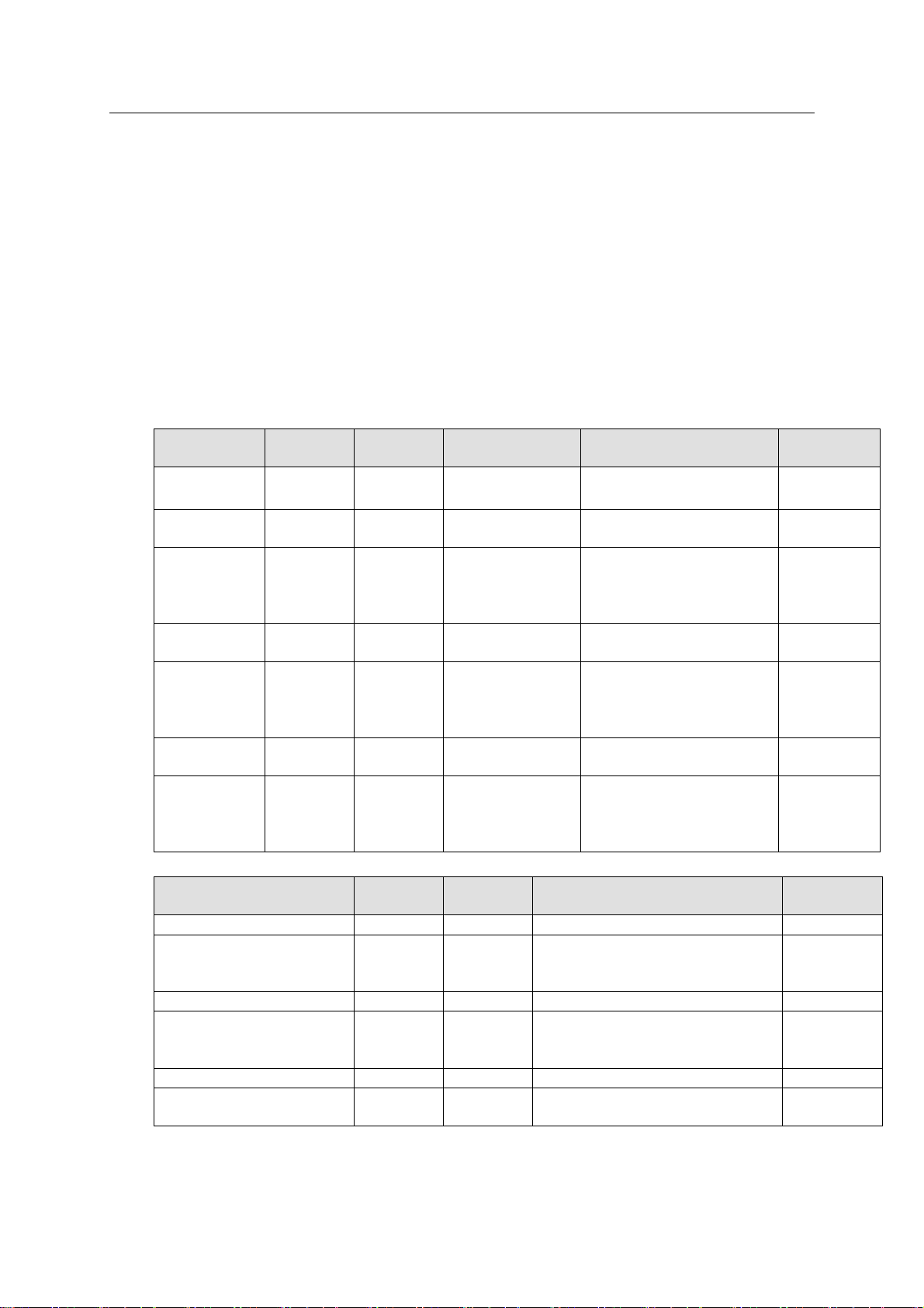
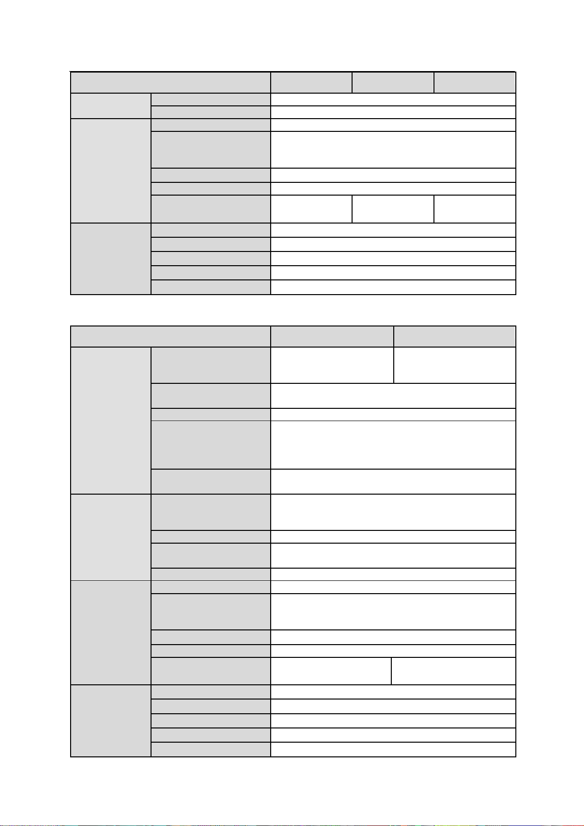
Model
Case
Height
HDD No.
Power Mode
Network Setup
Controller
No.
ESS2016X
3U
16
Single-power
supplying
LAN1/LAN2/WEB
1
ESS3116X
3U
16
Single-power
supplying
LAN1/LAN2/LAN3/LAN4
ESS5016S/
ESS5016SR
3U
16
Single-power
supplying/redun
dancy-power
supplying
LAN1/LAN2/LAN3/LAN4/
WEB
1
ESS5016D-
R
3U
16
Redundancypower supplying
LAN1/LAN2/LAN3/LAN4/
10G_1/10G_2/WEB
2
ESS5024S/
ESS5024SR
4U
24
Single-power
supplying/redun
dancy-power
supplying
LAN1/LAN2/LAN3/LAN4/
WEB
1
ESS5024D-
R
4U
24
Redundancypower supplying
LAN1/LAN2/LAN3/LAN4/
10G_1/10G_2/WEB
2
ESS5048S/
ESS5048SR
8U
48
Redundancypower
supplying/4power supplying
LAN1/LAN2/LAN3/LAN4/
WEB
1
Model
Case
Height
HDD No.
Power Mode
Network
Setup
ESS2016X-J
3U
16
Single-power supplying
1
ESS3116S-J/ESS3116SJR
3U
16
Single-power
supplying/redundancy-power
supplying
1
ESS3116D-JR
3U
16
Redundancy-power supplying
2
ESS3124S-J/ESS3124SJR
4U
24
Single-power
supplying/redundancy-power
supplying
1
ESS3124D-JR
4U
24
Redundancy-power supplying
2
ESS3148S-J/ESS3148SJR
8U
48
Redundancy-power
supplying/4-power supplying
1
1 Overview
The ESS internet intelligent storage unit is a storage disk array product. It provides standard
network file share service and realizes IPSAN/NAS total solutions. It is a centralized storage
solutions of high-capacity, high expansion, and high security. The host supports disk array
enclosure to extend its storage capacity.
The disk array enclosure is mainly to connect the host to extend network storage device capacity.
1.1 Model List
This user’s manual is to introduce the following products. Please refer to the following sheet for
detailed information.
1.1.1 Host Model
1.1.2 Disk Array Enclosure Model
Page 11
2
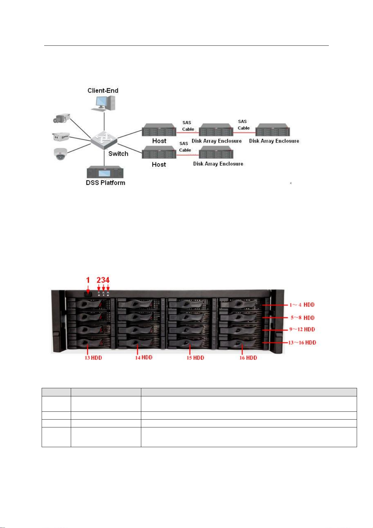
1.2 Connection Sample
SN
Name
Function
1
Power on-off button
Press it to boot up the device.
Press it for 5 seconds to shut down the device.
2
HDD Indicator Light
When system HDD is reading or writing, the blue light becomes flash.
3
Alarm Indicator Light
The red light is flashing when there is an alarm or abnormal situation.
4
Network Indicator
Light
The blue light is flashing when the network connection is OK.
The connection sample is shown as in Figure 1-1.
Figure 1-1
ESS Series User’s Manual
1.3 ESS2016X
1.3.1 Front Panel
The front panel is shown as below. See Figure 1-2.
The HDD slot number ranges from left to right, from top to the bottom.
Figure 1-2
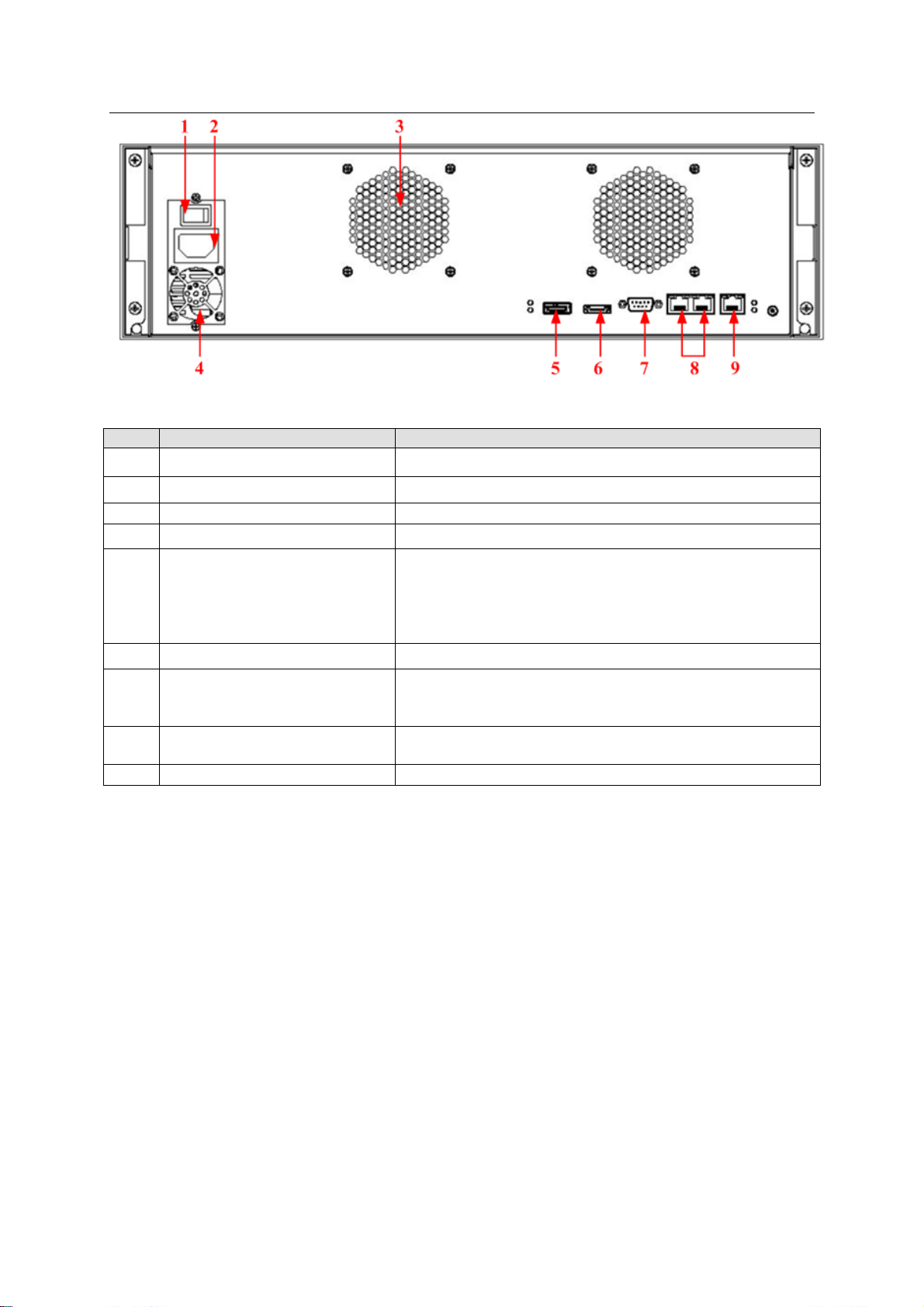
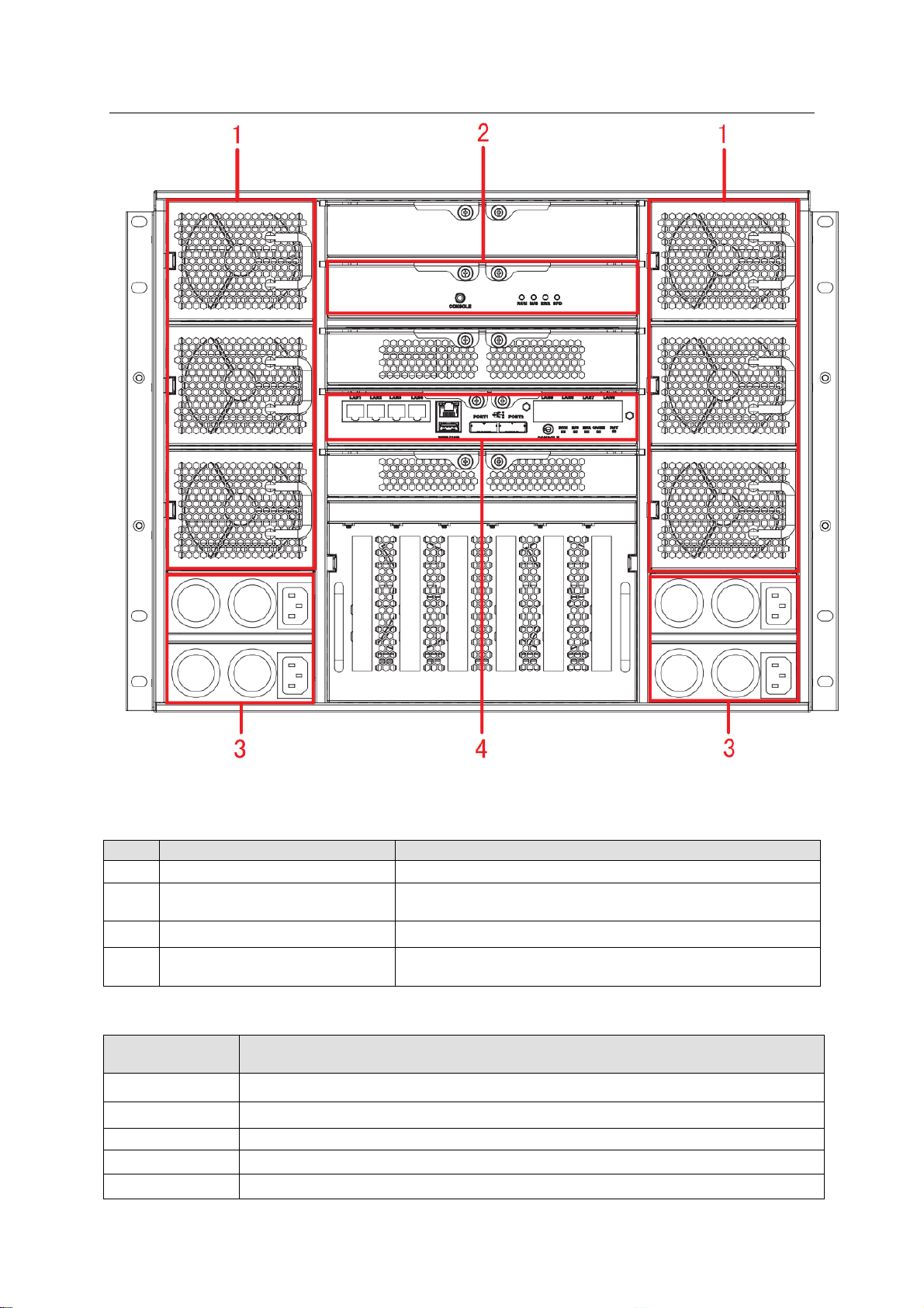
1.3.2 Rear Panel
The rear panel is shown as below. See Figure 1-3.
Page 12
3
Figure 1-3
SN
Port
Function
1
Power on-off button
Connect or cut off the device power.
2
Power Port
Connect to AC power supplying.
3
Case fan
It is for case ventilation.
4
Power fan
It is for power ventilation
5
SAS port
Connect to IN port of the disk array enclosure.
LINK light: The light becomes on when the disk array
enclosure is connected.
ACCESS light: The light flashes when the host is visiting
disk array enclosure.
6
eSATA port
It is reserved port for future development.
7
RS232 port
It is to debug device and login command interface.
Please refer to chapter 9 for detailed command
operation information.
8 LAN1, LAN2
Two data Ethernet ports. It is to transmit data.
9
WEB port
Ethernet Management port. Login Web via this port.
ESS Series User’s Manual
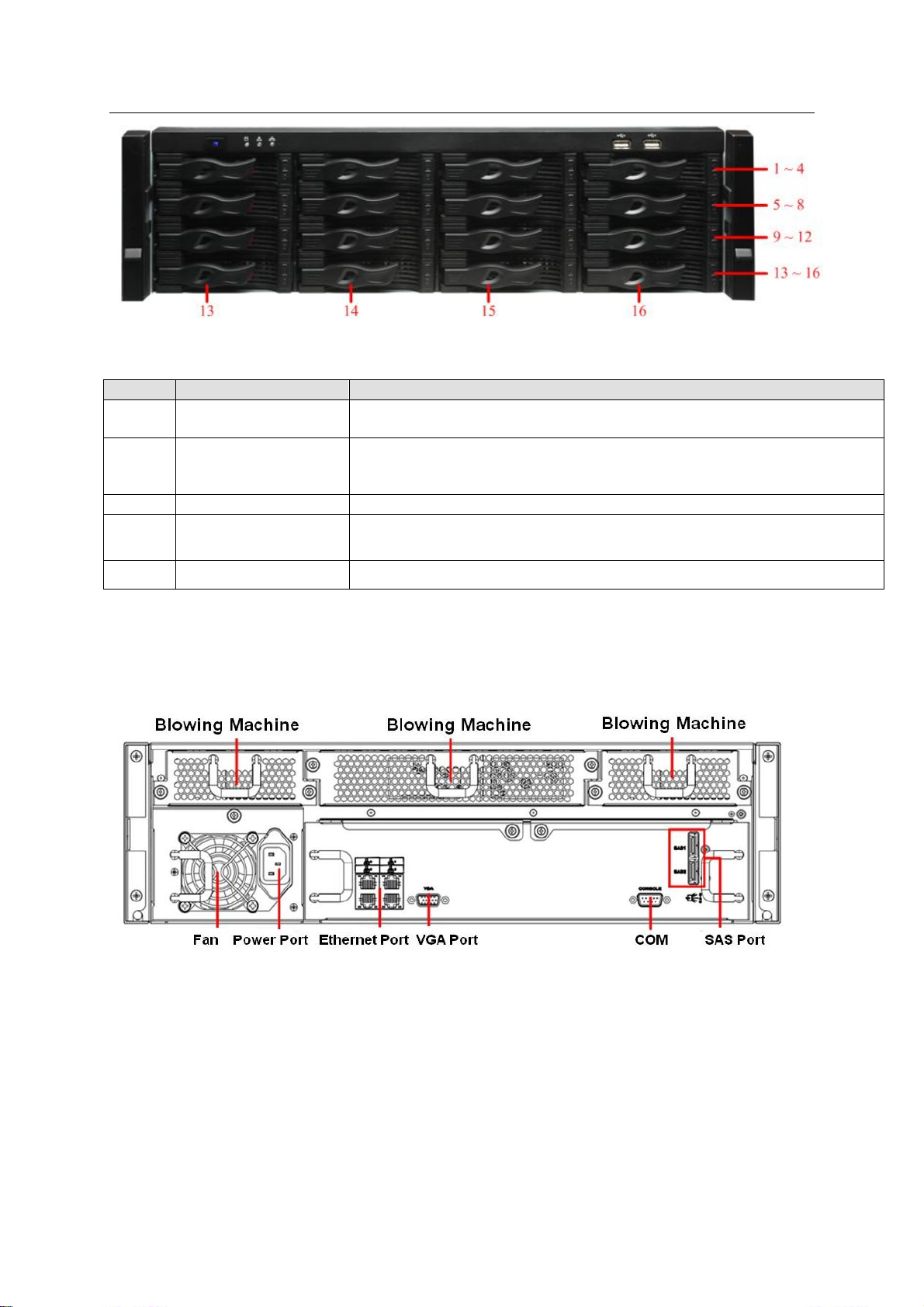
1.4 ESS3116X
1.4.1 Front Panel
The front panel is shown as in Figure 2-1.
In Figure 2-1, you can view HDD serial number. The value ranges from left to the right. You can
see the 13th to 16th at the bottom of the unit.
You can use the HDD bracket in the chassis to install HDD.
a) Pull out HDD bracket from the front panel.
b) Use four screws to fix one HDD in the HDD bracket firmly.
Page 13
4
Figure 1-4
SN
Name
Function
1
Power on-off button
Press it to boot up the device.
Press it for a long time to reboot the device.
2
System HDD
Indicator Light
When system HDD is reading or writing, the blue light becomes flash.
The system HDD storage the important configuration files of the device,
factory default configuration files and device initial boot up data.
3
Alarm Indicator Light
The red light is flashing when there is an alarm or abnormal situation.
4
Network Indicator
Light
The blue light is flashing when the network connection is OK.
5.6
USB port
Connect to USB device.
ESS Series User’s Manual
1.4.2 Rear Panel
ESS3116X series product has two kinds of rear panels. There are slightly difference on the
power supplying module and fan module.
The single-power supplying interface is shown as In Figure 1-8.
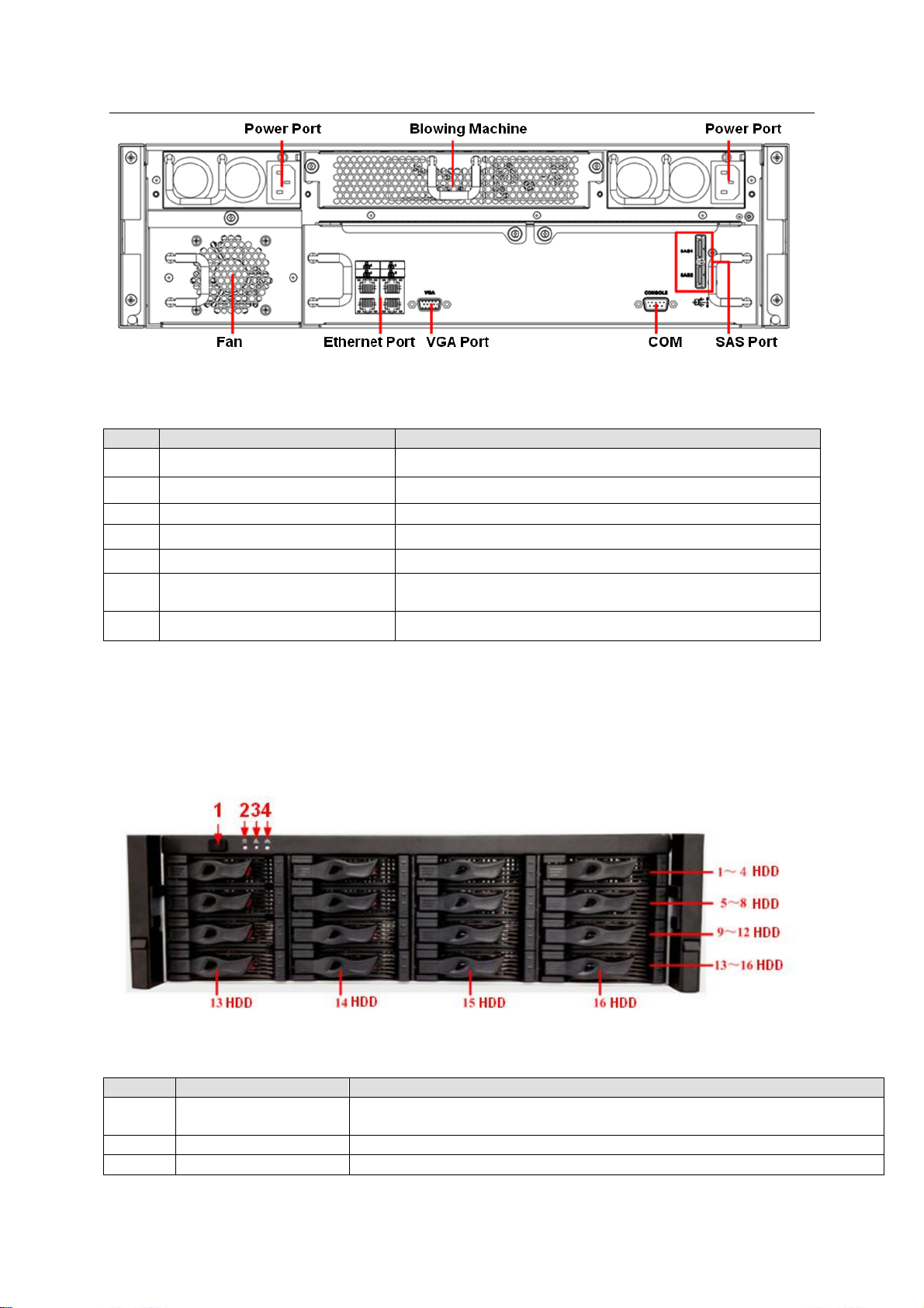
Figure 1-5
The redundancy-power supplying rear panel is shown as below. See Figure 1-9.
Page 14
ESS Series User’s Manual
5
SN
Port
Function
1
Power Port
Connect to 220V AC.
2
Blowing machine
It is for ventilation.
3
Fan
It is for ventilation.
4
Ethernet port
It is used to transmit data. 1000M Ethernet port.
5
VGA port
Connect to monitor.
6
COM
Connect to RS232 COM to go to the command
interface.
7
SAS port
Connect to disk array enclosure.
SN
Name
Function
1
Power on-off button
Press it to boot up the device.
Press it for 5 seconds to shut down the device.
2
HDD Indicator Light
When system HDD is reading or writing, the blue light becomes flash.
3
Alarm Indicator Light
The red light is flashing when there is an alarm or abnormal situation.
Figure 1-6
You can refer to the following sheet for detailed information.
1.5 ESS5016S/ ESS5016S-R
1.5.1 Front Panel
The front panel is shown as below. See Figure 1-7.
The HDD slot number ranges from left to right, from top to the bottom.
Figure 1-7
Page 15
ESS Series User’s Manual
6
4
Network Indicator
Light
The blue light is flashing when the network connection is OK.
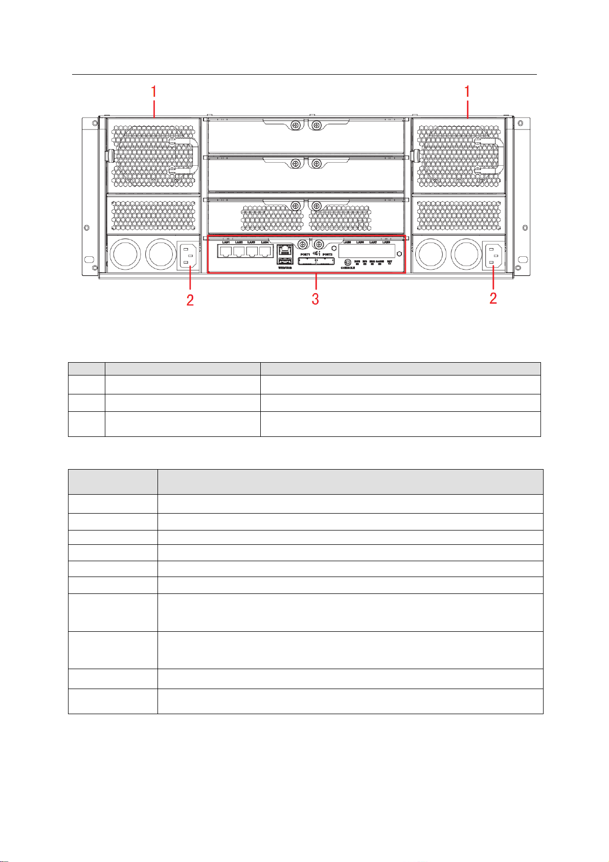
SN
Port
Function
1
Power Port
Connect to AC power supplying.
2
Power on-off button
Connect or cut off the device power.
3
Case fan
It is for case ventilation.
4
Blower
It is for case ventilation.
5
Main control module
It is about all kinds of ports and indictor light
introduction. Please refer to the following sheet.
6
Blower
It is for case ventilation.
1.5.2 Rear Panel
This series product has two kinds of rear panels. There are slightly difference on the power
supplying module and fan module.
The single-power supplying interface is shown as In Figure 1-8.
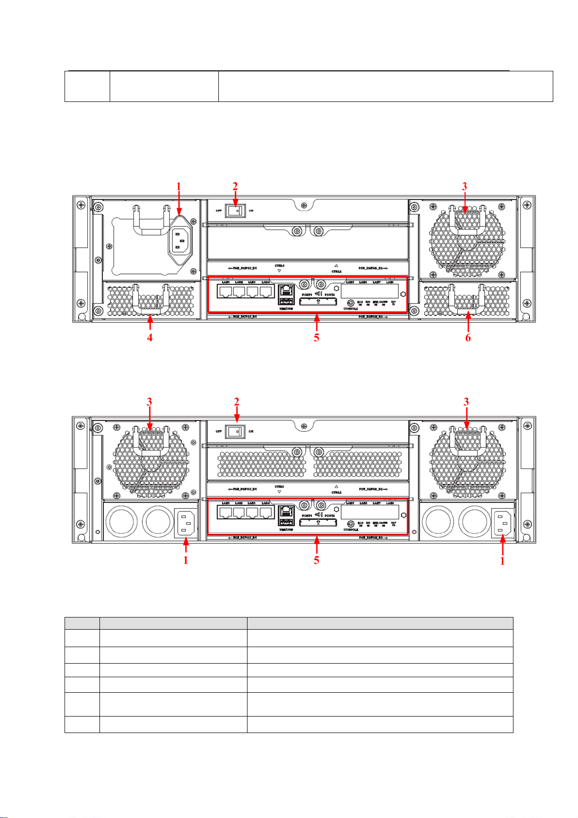
Figure 1-8
The redundancy-power supplying rear panel is shown as below. See Figure 1-9.
Figure 1-9
You can refer to the following sheet for detailed information.
Page 16
ESS Series User’s Manual
7
SN
Function
LAN1~LAN8
Data Ethernet port. It is to transmit data.
WEB port
Ethernet Management port. Login Web via this port.
USB port
USB port
PORT1/PORT2
Connect to the IN port of the disk array enclosure.
CONSOLE
COM port. It is to debug the device and view the login command interface.
Refer to Appendix D for detailed information.
RUN
The light is on after system booted up and begins running.
M/S
Main control indictor light.
The light is on when system is malfunction.
The light is off when system is running properly.
ERR
System error indictor light.
The error light is on when system is abnormal.
The error light is off when system is running properly.
CACHE
It is reserved for future use.
RST
Press it for 5 seconds to restore default setup (network setup, user password,
time sync, email alarm and etc.).
SN
Name
Function
①
Power on-off button
Press it to boot up the device.
Press it for 5 seconds to shut down the device.
②
HDD Indicator Light
When system HDD is reading or writing, the blue light becomes flash.
③
Alarm Indicator Light
The red light is flashing when there is an alarm or abnormal situation.
④
Network Indicator
Light
The blue light is flashing when the network connection is OK.
You can refer to the following sheet for master control module information.
1.6 ESS5016D-R
1.6.1 Front Panel
The front panel is shown as in Figure 1-10.
The HDD slot number ranges from left to right, from top to the bottom.
Figure 1-10
1.6.2 Rear Panel
Page 17
ESS Series User’s Manual
8
SN
Port
Function
1
Power port
Connect to AC power supplying source.
2
Battery box
It is to install the battery box.
3
Fan
It is for case ventilation.
4
Main control module
It is about all kinds of ports and indictor light
introduction. Please refer to the following sheet.
Port/Indicator
Light
Function
LAN1~LAN4
1000Mbps data Ethernet port. It is to transmit data.
10G_1, 10G_2
10000Mbps data Ethernet port. It is to transmit data. (Optional)
WEB port
Ethernet Management port. Login Web via this port.
USB port
USB port
PORT1/PORT2
Connect to the IN port of the disk array enclosure.
CONSOLE
COM port. It is to debug the device and view the login command interface.
RUN
The light is flashing after system booted up and begins running.
M/S
Main control indictor light.
The light is on if it is the main controller.
The light is off if it is the slave controller.
ERR
System error indictor light.
The error light is on when system is abnormal.
The error light is off when system is running properly.
CACHE
It is reserved for future use.
RST
Press it for 5 seconds to restore default setup (network setup, user password,
time sync, email alarm and etc.).
The interface is shown as In Figure 1-11.
Figure 1-11
You can refer to the following sheet for detailed information of the rear panel.
You can refer to the following sheet for detailed information of main control module.
1.7 ESS5024S/ ESS5024S-R
Page 18

ESS Series User’s Manual
9
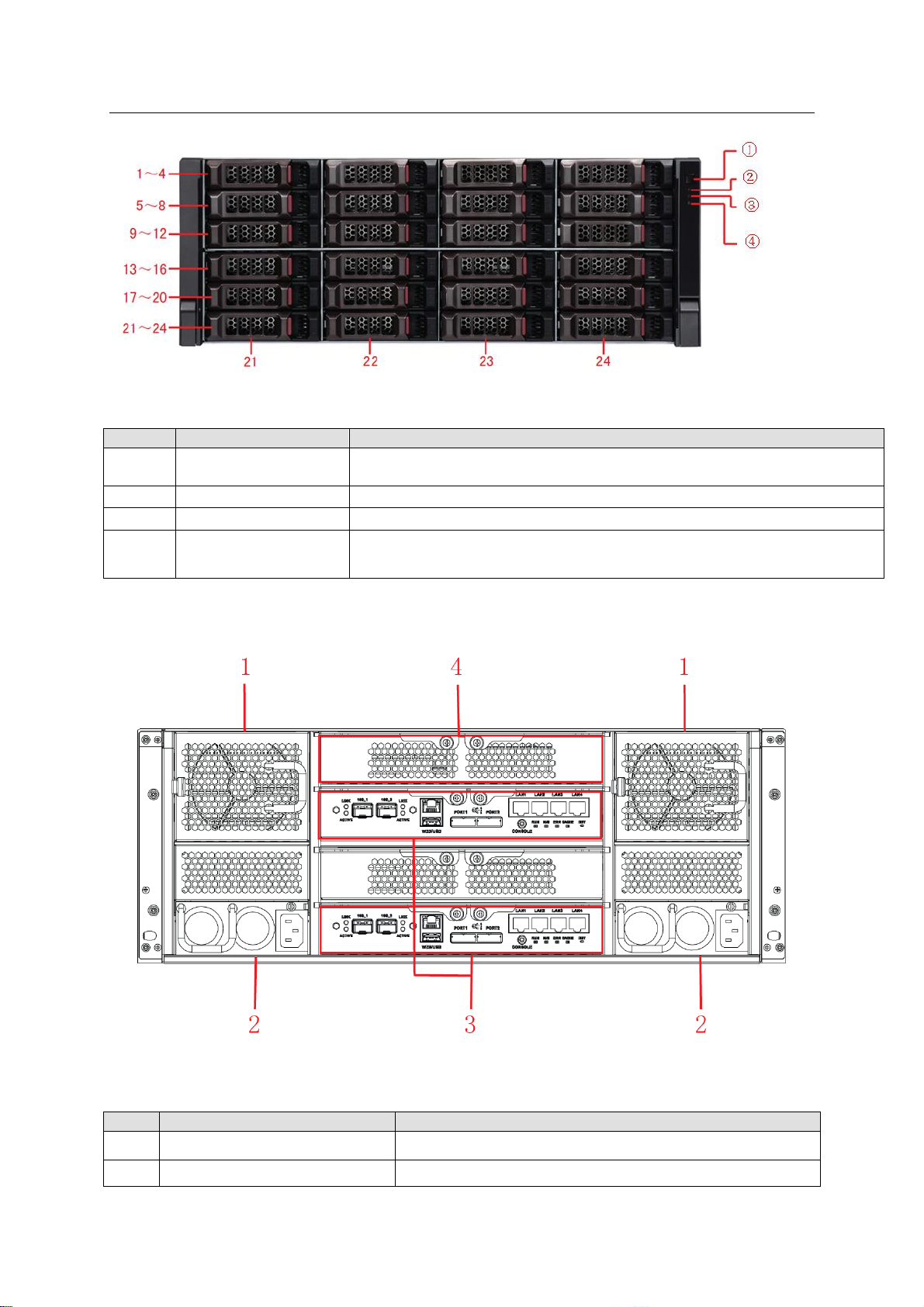
SN
Name
Function
①
Power on-off button
Press it to boot up the device.
Press it for 5 seconds to shut down the device.
②
HDD Indicator Light
When system HDD is reading or writing, the blue light becomes flash.
③
Alarm Indicator Light
The red light is flashing when there is an alarm or abnormal situation.
④
Network Indicator
Light
The blue light is flashing when the network connection is OK.
1.7.1 Front Panel
The front panel is shown as below. See Figure 1-12.
The HDD slot number ranges from left to right, from top to the bottom.
Figure 1-12
1.7.2 Rear Panel
This series product has two kinds of rear panels. There are slightly difference on the power
supplying module and fan module.
The single-power supplying interface is shown as In Figure 1-13.
The redundancy-power supplying rear panel is shown as below. See Figure 1-14.
Figure 1-13
Page 19
ESS Series User’s Manual
10
SN
Port
Function
1
Fan
It is for case ventilation.
2
Power port
Connect to AC power supplying source.
3
Main control module
It is about all kinds of ports and indictor light
introduction. Please refer to the following sheet.
Port/Indicator
Light
Function
LAN1~LAN8
Data Ethernet port. It is to transmit data.
WEB port
Ethernet Management port. Login Web via this port.
USB port
USB port
PORT1/PORT2
Connect to the IN port of the disk array enclosure.
CONSOLE
COM port. It is to debug the device and view the login command interface.
RUN
The light is flashing after system booted up and begins running.
M/S
Main control indictor light.
The light is on when system is malfunction.
The light is off when system is running properly.
ERR
System error indictor light.
The error light is on when system is abnormal.
The error light is off when system is running properly.
CACHE
It is reserved for future use.
RST
Press it for 5 seconds to restore default setup (network setup, user password,
time sync, email alarm and etc.).
Figure 1-14
You can refer to the following sheet for detailed information of the rear panel.
You can refer to the following sheet for detailed information of main control module.
1.8 ESS5024D-R
1.8.1 Front Panel
The ESS5024D-R front panel is shown as below. See Figure 1-15.
Page 20
ESS Series User’s Manual
11
SN
Name
Function
①
Power on-off button
Press it to boot up the device.
Press it for 5 seconds to shut down the device.
②
HDD Indicator Light
When system HDD is reading or writing, the blue light becomes flash.
③
Alarm Indicator Light
The red light is flashing when there is an alarm or abnormal situation.
④
Network Indicator
Light
The blue light is flashing when the network connection is OK.
SN
Port
Function
1
Fan
It is for case ventilation.
2
Power port
Connect to AC power supplying source.
The HDD slot number ranges from left to right, from top to the bottom.
Figure 1-15
1.8.2 Rear Panel
The interface is shown as In Figure 1-16.
You can refer to the following sheet for detailed information of the rear panel.
Figure 1-16
Page 21

ESS Series User’s Manual
12
3
Main control module
It is about all kinds of ports and indictor light
introduction. Please refer to the following sheet.
4
Battery&fan box
It is to install the battery and the case ventilation.
Port/Indicator
Light
Function
LAN1~LAN4
1000Mbps data Ethernet port. It is to transmit data.
10G_1, 10G_2
10000Mbps data Ethernet port. It is to transmit data. (Optional)
WEB port
Ethernet Management port. Login Web via this port.
USB port
USB port
PORT1/PORT2
Connect to the IN port of the disk array enclosure.
CONSOLE
COM port. It is to debug the device and view the login command interface.
RUN
The light is flashing after system booted up and begins running.
M/S
Main control indictor light.
The light is on if it is the main controller.
The light is off if it is the slave controller.
ERR
System error indictor light.
The error light is on when system is abnormal.
The error light is off when system is running properly.
CACHE
It is reserved for future use.
RST
Press it for 5 seconds to restore default setup (network setup, user password,
time sync, email alarm and etc.).
You can refer to the following sheet for detailed information of main control module.
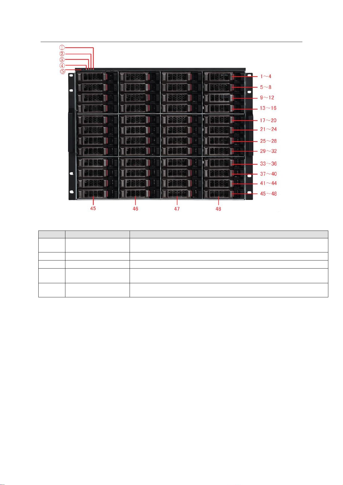
1.9 ESS5048S/ ESS5048S-R
1.9.1 Front Panel
The front panel is shown as below. See Figure 1-17.
The HDD slot number ranges from left to right, from top to the bottom.
Page 22
ESS Series User’s Manual
13
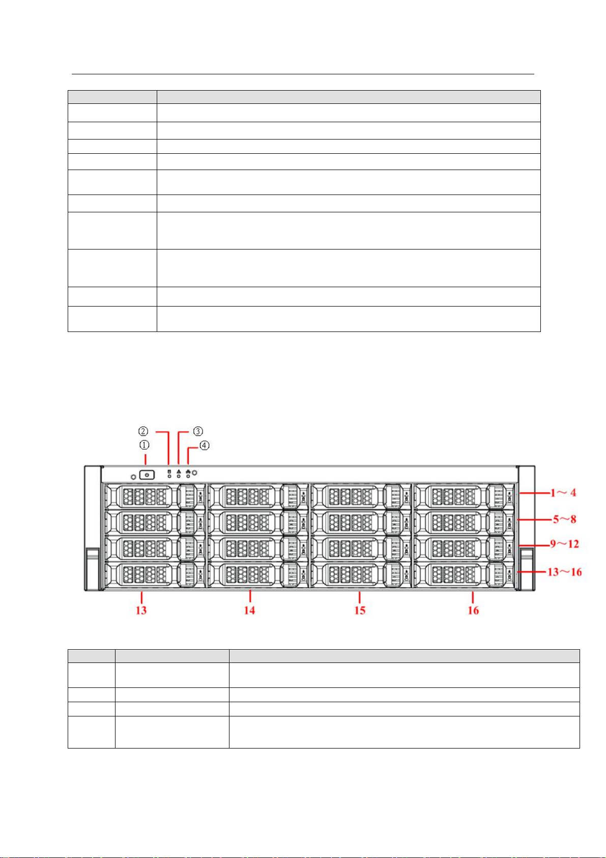
SN
Name
Function
①
Power on-off button
Press it to boot up the device.
Press it for 5 seconds to shut down the device.
②
Power Indicator Light
When the light is blue, the power connection is OK.
③
HDD Indicator Light
When system HDD is reading or writing, the blue light becomes flash.
④
Alarm Indicator Light
The red light is flashing when there is an alarm or abnormal situation.
⑤
Network Indicator
Light
The blue light is flashing when the network connection is OK.
Figure 1-17
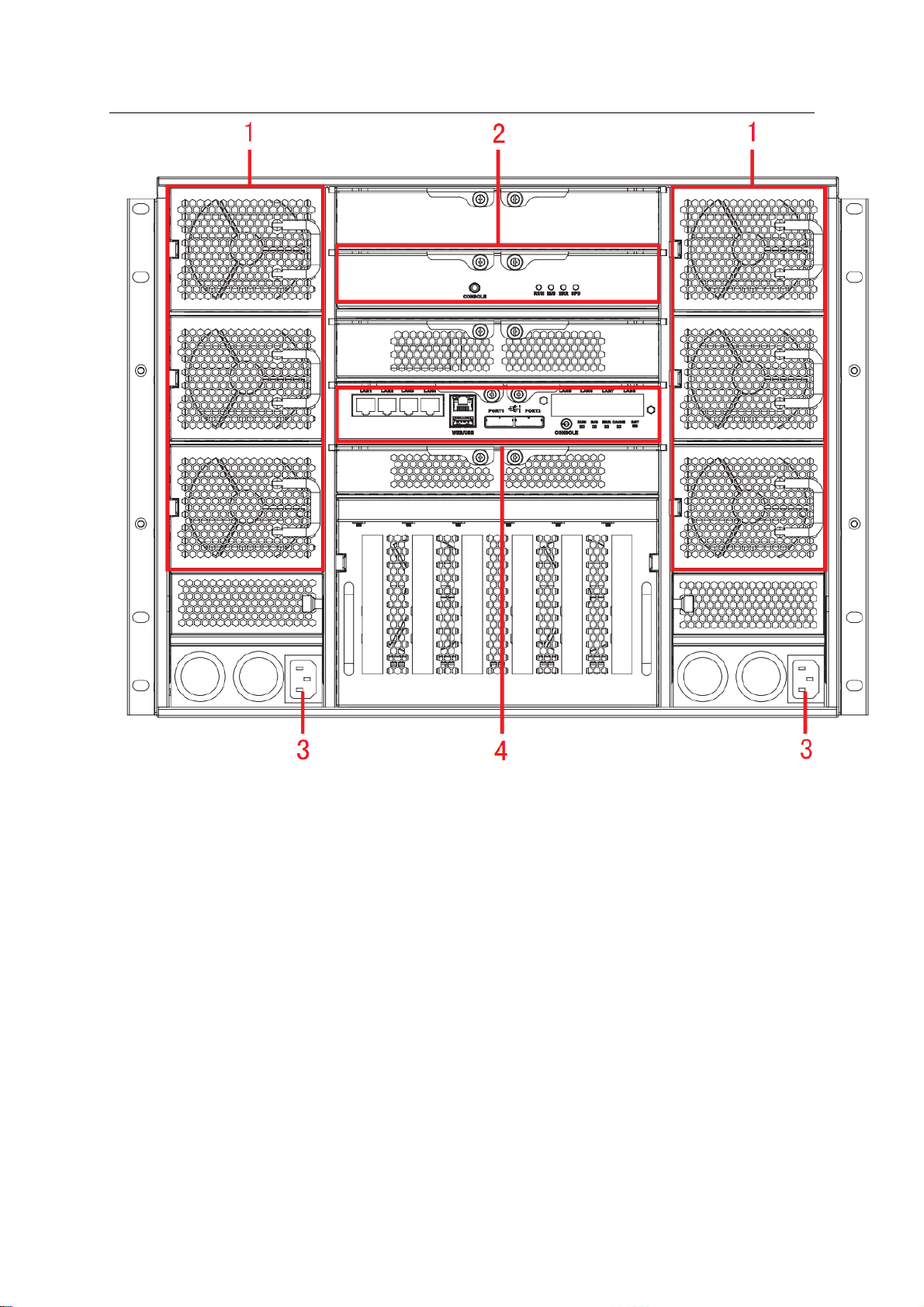
1.9.2 Rear Panel
This series product has two kinds of rear panels. There are slightly difference on the power
supplying module and fan module.
The redundancy-power supplying interface is shown as In Figure 1-18.
Page 23
ESS Series User’s Manual
14
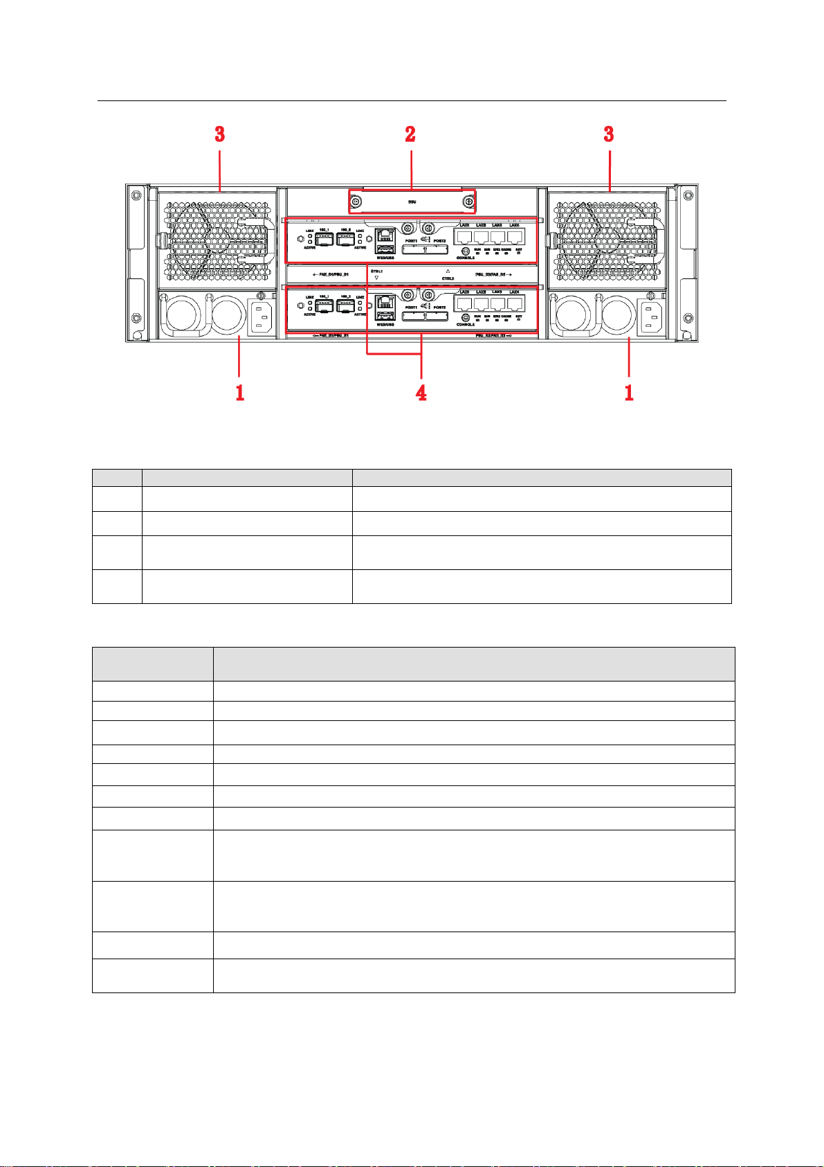
Figure 1-18
The four-power supplying rear panel is shown as below. See Figure 1-19.
Page 24
ESS Series User’s Manual
15
SN
Port
Function
1
Fan
It is for case ventilation.
2
Slave control module
It is about all kinds of ports and indictor light
introduction. Please refer to the following sheet.
3
Power port
Connect to AC power supplying source.
4
Main control module
It is about all kinds of ports and indictor light
introduction. Please refer to the following sheet.
Port/Indicator
Light
Function
LAN1~LAN8
Data Ethernet port. It is to transmit data.
WEB port
Ethernet Management port. Login Web via this port.
USB port
USB port
PORT1/PORT2
Connect to the IN port of the disk array enclosure.
CONSOLE
COM port. It is to debug the device and view the login command interface.
Figure 1-19
You can refer to the following sheet for detailed information of the rear panel.
You can refer to the following sheet for master control module information.
Page 25
ESS Series User’s Manual
16
RUN
The light is flashing after system booted up and begins running.
M/S
Main control indictor light.
The light is on when system is malfunction.
The light is off when system is running properly.
ERR
System error indictor light.
The error light is on when system is abnormal.
The error light is off when system is running properly.
CACHE
It is reserved for future use.
RST
Press it for 5 seconds to restore default setup (network setup, user password,
time sync, email alarm and etc.).
Port/Indicator
Light
Function
CONSOLE
COM port. It is to debug the device and view the login command interface.
RUN
The light is flashing after system booted up and begins running.
M/S
Slave control indictor light.
The light is on when system is malfunction.
The light is off when system is running properly.
ERR
System error indictor light.
The error light is on when system is abnormal.
The error light is off when system is running properly.
SPD
SAS speed indicator light.
When the running speed is 6G, the light is off.
When the running speed is 3G, the light becomes on to alert you.
Model
ESS2016X
System
Main
processer
Multiple-core special storage CPU
OS
Embedded LINUX OS
Power Mode
Single power supplying mode
Fan
Redundant dual ball bearing fan
MTBF>100 thousand hours
Motherboard
Server(Support 7x24H work)
Storage
Default 4G
Case
Self-developed case,
1.2mm extra-thickness hot-dip galvanized steel.
Self-developed patent removable HDD bracket.
Setup
Interface
WEB GUI
Storage
Protocol
Storage
Protocol
iSCSI
Video
Capacity
Input Video
128-channel: 2Mbps
64-channel: 4Mbps
32-channel: 8Mbps
Data
Management
HDD No.
16 HDDs.
Support SAS/SATA HDD.
Each HDD max supports 4T.
RAID Mode
RAID0/RAID1/RAID3/RAID5/RAID6/RAID10/RAID50/RAID60/JBOD
one HDD/global hotspare HDD.
You can refer to the following sheet for slave control module information.
1.10 Host Specifications
1.10.1 ESS2016X
Page 26
ESS Series User’s Manual
17
Model
ESS2016X
HDD
Installation
Independent HDD bracket. Support HDD hot swap.
HDD
Hotspare
Support global hotspare HDD
Disk Array
Enclosure
Max 2-level cascade connection.
Network Port
Management
Network Port
One 10/100/1000Mbps Ethernet port
Data Network
port
Two 10/100/1000Mbps Ethernet ports
Specifications
Dimensions
Power
Consumption
100V~240V, 50Hz~60Hz
Whole
Device
Power
Consumption
Below 400W(With HDD),Below 200W(No HDD)
H×W×D
133mm×448mm×472mm
Installation
Mode
Standard 19-inch rack installation
Net Weight
15kg
Environments
Requirements
Working
Environment
Temperature
0℃~40℃
Working
Environment
Humidity
10%~80% (Non condensation)
Storage
Environment
Temperature
-20℃~70℃
Storage
Environment
Humidity
5%~90% (Non condensation)
Working
Altitude
-60m~5000m
Model
ESS3116X
System
Main processer
Intel SandyBridge 64-bit multiple-core CPU
OS
Embedded LINUX OS
Power Mode
Single power supplying mode/ Redundancy-power
supplying mode.
Fan
Redundant dual ball bearing fan
MTBF>100 thousand hours
Support online replacement
Motherboard
Server(Support 7x24H work)
Storage
Default 4G, max 8G.
Case
Self-developed case,
1.2mm extra-thickness hot-dip galvanized steel.
Self-developed patent removable HDD bracket.
Setup Interface
WEB GUI
Storage
Protocol
Storage
Protocol
iSCSI/SAMBA/NFS/FTP
Video
Capacity
Input Video
192-channel D1: 2Mbps
96-channel 720P: 4Mbps
1.10.2 ESS3116X
Page 27

ESS Series User’s Manual
18
Model
ESS3116X
48-channel 1080P: 8Mbps
Data
Management
HDD No.
16 SATAⅡHDDs.
Each HDD max supports 4T.
RAID Mode
Raid0/Raid1/Raid5/Raid6/JBOD/one HDD
HDD
Installation
Independent HDD bracket. Support HDD hot swap.
HDD Hotspare
Support global hotspare HDD
Disk Array
Enclosure
Max 2-level cascade connection.
Network Port
Network Port
Four 10/100/1000Mbps Ethernet ports
Data Network
port
Multiple-Ethernet port load balance binding, or four
1000Mbps Ethernet ports
General
Supported OS
Windows, Linux, Unix and etc.
Management
Mode
Configuration and management function via the WEB.
Expansibility
Connect to peripheral disk array enclosure
Standardization
Total standard device, compatible with various software
platforms.
Specifications
Dimensions
Power
Consumption
100V~240V, 47Hz~63Hz
Whole Device
Power
Consumption
Below 400W(With HDD),Below 200W(No HDD)
H×W×D
133mm×448mm×472mm
Installation
Mode
Standard 19-inch rack installation
Net Weight
19.5kg
Environments
Requirements
Working
Environment
Temperature
0℃~40℃
Working
Environment
Humidity
10%~80% (Non condensation)
Storage
Environment
Temperature
-20℃~70℃
Storage
Environment
Humidity
5%~90% (Non condensation)
Working
Altitude
-60m~3000m
Model
ESS5016S
ESS5016S-R
System
Main
processer
Multiple-core special storage 64-bit CPU
OS
Embedded LINUX OS
Power Mode
400W. Single power supplying
mode. Support online update.
400W. Redundancy-power
supplying mode. Support online
update.
Fan
Redundant dual ball bearing fan
MTBF>100 thousand hours
Motherboard
Server(Support 7x24H work)
1.10.3 ESS5016S/ ESS5016S-R
Page 28

ESS Series User’s Manual
19
Model
ESS5016S
ESS5016S-R
Storage
Default 4G. With ECC verification.
Case
Self-developed case,
1.2mm extra-thickness hot-dip galvanized steel.
Self-developed patent removable HDD bracket.
SBB2.0 specifications compliance.
Setup
Interface
WEB GUI
Storage
Protocol
Storage
Protocol
iSCSI,SAMBA,NFS,FTP
Video
Capacity
Input Video
256-channel: 2Mbps
128-channel: 4Mbps
64-channel: 8Mbps
Data
Management
HDD No.
16 HDDs.
Support SAS/SATA HDD.
Each HDD max supports 4T.
RAID Mode
RAID0/RAID1/RAID3/RAID5/RAID6/RAID10/RAID50/RAID60/JBOD
one HDD/global hotspare HDD.
HDD
Installation
Independent HDD bracket. Support HDD hot swap.
HDD
Hotspare
Support global hotspare HDD
Disk Array
Enclosure
Max 4-level cascade connection.
Network Port
Management
Network Port
One 10/100/1000Mbps Ethernet port
Data Network
port
Four 10/100/1000Mbps Ethernet ports
Specifications
Dimensions
Power
Consumption
AC 100V~240V ±10% 60Hz/50Hz
Whole
Device
Power
Consumption
Below 400W(With HDD)
H×W×D
133.2mm×448.0mm×490.4mm
Installation
Mode
Standard 19-inch rack installation
Net Weight
(Without
HDD)
24kg
Environments
Requirements
Working
Environment
Temperature
0℃~40℃
Working
Environment
Humidity
10%~80% (Non condensation)
Storage
Environment
Temperature
-20℃~70℃
Storage
Environment
Humidity
5%~90% (Non condensation)
Working
Altitude
-60m~5000m
1.10.4 ESS5016D-R
Page 29

ESS Series User’s Manual
20
Model
ESS5016D-R
System
Controller
Dual-controller
Main
processer
Two Intel multiple-core processors
OS
Embedded LINUX OS
Power Mode
500W. Redundancy-power supplying mode. Support online update.
Fan
Redundant dual ball bearing fan
MTBF>100 thousand hours
Motherboard
Server(Support 7x24H work)
Storage
Default 16G. With ECC verification. Max 32GB.
Case
Self-developed case,
1.2mm extra-thickness hot-dip galvanized steel.
Self-developed patent removable HDD bracket.
SBB2.0 specifications compliance.
Setup
Interface
WEB GUI
Storage
Protocol
Storage
Protocol
iSCSI,SAMBA,NFS,FTP,AFP,HTTP
Video
Capacity
Input Video
400-channel: 2Mbps
Data
Management
HDD No.
16 HDDs.
Support SAS/SATA (need adapter. NOT PROVIDED.)/SSD HDD.
Each HDD max supports 4T.
RAID Mode
RAID0/RAID1/RAID3/RAID5/RAID6/RAID10/RAID50/RAID60/JBOD
one HDD/global hotspare HDD.
HDD
Installation
Independent HDD bracket. Support HDD hot swap.
Disk Array
Enclosure
Support disk array enclosure of dual-controller construction.
Max 4-level cascade connection.
Data
protection
Data protection in case of power outage.
Network Port
Management
Network Port
Two 10/100/1000Mbps Ethernet ports
Data Network
port
Eight 10/100/1000Mbps Ethernet ports. Can extend four 10Gbps
high-speed Ethernet ports.
UBS Port
2 USB ports
Specifications
Dimensions
Power
Consumption
AC 100V~240V ±10% 60Hz/50Hz
Whole
Device
Power
Consumption
Below 400W(With HDD)
H×W×D
133.2mm×446.0mm×493.0mm
Installation
Mode
Standard 19-inch rack installation
Net Weight
(Without
HDD)
30kg
Environments
Requirements
Working
Environment
Temperature
0℃~40℃
Working
Environment
10%~80% (Non condensation)
Page 30
21
Model
ESS5016D-R
Humidity
Storage
Environment
Temperature
-20℃~70℃
Storage
Environment
Humidity
5%~90% (Non condensation)
Working
Altitude
-60m~5000m
Model
ESS5024S
ESS5024S-R
System
Main
processer
Multiple-core special storage 64-bit CPU
OS
Embedded LINUX OS
Power Mode
500W. Single power supplying
mode. Support online update.
500W. 1+1 Redundancy-power
supplying mode. Support online
update.
Fan
Redundant dual ball bearing fan
MTBF>100 thousand hours
Motherboard
Server(Support 7x24H work)
Storage
Default 4G. Max 8G.
Case
Self-developed case,
1.2mm extra-thickness hot-dip galvanized steel.
Self-developed patent removable HDD bracket.
SBB2.0 specifications compliance.
Setup
Interface
WEB GUI
Storage
Protocol
Storage
Protocol
iSCSI,SAMBA,NFS,FTP
Video
Capacity
Input Video
256-channel D1
128-channel 720P
64-channel 1080P
Data
Management
HDD No.
24 HDDs.
Support SAS/SATA HDD.
Each HDD max supports 4T.
RAID Mode
RAID0/RAID1/RAID3/RAID5/RAID6/RAID10/RAID50/RAID60/JBOD
one HDD/global hotspare HDD.
HDD
Installation
Independent HDD bracket. Support HDD hot swap.
HDD
Hotspare
Support global hotspare HDD and special hotspare HDD.
Disk Array
Enclosure
Max 4-level cascade connection.
Network Port
Management
Network Port
One 10/100/1000Mbps Ethernet port
Data Network
port
Four 10/100/1000Mbps Ethernet ports. Support load balance and
network adapter binding.
Specifications
Dimensions
Power
Consumption
AC 100V~240V ±10% 60Hz/50Hz
Whole
Device
Power
Consumption
Below 500W(With HDD)
1.10.5 ESS5024S/ ESS5024S-R
ESS Series User’s Manual
Page 31

ESS Series User’s Manual
22
Model
ESS5024S
ESS5024S-R
H×W×D
446mm×175mm×495mm
Installation
Mode
Standard 19-inch rack installation
Net Weight
(Without
HDD)
26.7kg
26.8kg
Environments
Requirements
Working
Environment
Temperature
0℃~40℃
Working
Environment
Humidity
10%~80% (Non condensation)
Storage
Environment
Temperature
-20℃~70℃
Storage
Environment
Humidity
5%~90% (Non condensation)
Working
Altitude
-60m~5000m
Model
ESS5024D-R
System
Controller
Dual-controller
Main
processer
Two Intel multiple-core processors
OS
Embedded LINUX OS
Power Mode
500W. Redundancy-power supplying mode. Support online update.
Fan
Redundant dual ball bearing fan
MTBF>100 thousand hours
Motherboard
Server(Support 7x24H work)
Storage
Default 16G. With ECC verification. Max 32GB.
Case
Self-developed case,
1.2mm extra-thickness hot-dip galvanized steel.
Self-developed patent removable HDD bracket.
SBB2.0 specifications compliance.
Setup
Interface
WEB GUI
Storage
Protocol
Storage
Protocol
iSCSI,SAMBA,NFS,FTP,AFP,HTTP
Video
Capacity
Input Video
400-channel: 2Mbps
Data
Management
HDD No.
24 HDDs.
Support SAS/SATA (need adapter. NOT PROVIDED.)/SSD HDD.
Each HDD max supports 4T.
RAID Mode
RAID0/RAID1/RAID3/RAID5/RAID6/RAID10/RAID50/RAID60/JBOD
one HDD/global hotspare HDD.
HDD
Installation
Independent HDD bracket. Support HDD hot swap.
Disk Array
Enclosure
Support disk array enclosure of dual-controller construction.
Max 4-level cascade connection.
1.10.6 ESS5024D-R
Page 32

ESS Series User’s Manual
23
Model
ESS5024D-R
Data
protection
Data protection in case of power outage.
Network Port
Management
Network Port
Two 10/100/1000Mbps Ethernet ports
Data Network
Port
Eight 10/100/1000Mbps Ethernet ports. Can extend four 10Gbps
high-speed Ethernet ports.
USB Port
2 USB ports
Specifications
Dimensions
Power
Consumption
AC 100V~240V ±10% 60Hz/50Hz
Whole
Device
Power
Consumption
Below 500W(With HDD)
H×W×D
178.0mm×446.0mm×493.0mm
Installation
Mode
Standard 19-inch rack installation
Net Weight
(Without
HDD)
34kg
Environments
Requirements
Working
Environment
Temperature
0℃~40℃
Working
Environment
Humidity
10%~80% (Non condensation)
Storage
Environment
Temperature
-20℃~70℃
Storage
Environment
Humidity
5%~90% (Non condensation)
Working
Altitude
-60m~5000m
Model
ESS5048S
ESS5048S-R
System
Main
processer
Multiple-core special storage 64-bit CPU
OS
Embedded LINUX OS
Power Mode
500W. 1+1 Redundancy-power
supplying mode. Support online
update.
500W. Four-power supplying
mode. Support online update.
Fan
Redundant dual ball bearing fan
MTBF>100 thousand hours
Motherboard
Server(Support 7x24H work)
Storage
Default 4G. Max 8G
Case
Self-developed case,
1.2mm extra-thickness hot-dip galvanized steel.
Self-developed patent removable HDD bracket.
SBB2.0 specifications compliance.
Setup
Interface
WEB GUI
Storage
Protocol
Storage
Protocol
iSCSI,SAMBA,NFS,FTP
1.10.7 ESS5048S/ ESS5048S-R
Page 33

ESS Series User’s Manual
24
Model
ESS5048S
ESS5048S-R
Video
Capacity
Input Video
256-channel D1
128-channel 720P
64-channel 1080P
Data
Management
HDD No.
48 HDDs.
Support SAS/SATA HDD.
Each HDD max supports 4T.
RAID Mode
RAID0/RAID1/RAID3/RAID5/RAID6/RAID10/RAID50/RAID60/JBOD
one HDD/global hotspare HDD.
HDD
Installation
Independent HDD bracket. Support HDD hot swap.
HDD
Hotspare
Support global hotspare HDD and special hotspare HDD.
Disk Array
Enclosure
Max 4-level cascade connection.
Network Port
Management
Network Port
One 10/100/1000Mbps Ethernet port
Data Network
port
Four 10/100/1000Mbps Ethernet ports. Support load balance and
network adapter binding.
Specifications
Dimensions
Power
Consumption
AC 100V~240V ±10% 60Hz/50Hz
Whole
Device
Power
Consumption
Below 1000W(With HDD)
H×W×D
445mm×353mm×495mm
Installation
Mode
Standard 19-inch rack installation
Net Weight
(Without
HDD)
48.6kg
50.2kg
Environments
Requirements
Working
Environment
Temperature
0℃~40℃
Working
Environment
Humidity
10%~80% (Non condensation)
Storage
Environment
Temperature
-20℃~70℃
Storage
Environment
Humidity
5%~90% (Non condensation)
Working
Altitude
-60m~5000m
Model
ESS2016X-J
System
Main
processer
Special storage CPU
OS
Embedded LINUX OS
Power Mode
Single power supplying mode
1.11 Disk Array Enclosure Specifications
1.11.1 ESS2016X-J
Page 34

ESS Series User’s Manual
25
Model
ESS2016X-J
Fan
Redundant dual ball bearing fan
MTBF>100 thousand hours
Motherboard
Server(Support 7x24H work)
Case
Self-developed case,
1.2mm extra-thickness hot-dip galvanized steel.
Self-developed patent removable HDD bracket.
Data
Management
HDD No.
16 HDDs.
Support SAS, SATA HDD.
Support 4T HDD
RAID Mode
RAID0/RAID1/RAID3/RAID5/RAID6/RAID10/RAID50/RAID60/JBOD
one HDD/global hotspare HDD.
HDD
Installation
Independent HDD bracket. Support HDD hot swap.
Data Port
miniSAS port
Specifications
Dimensions
Power
Consumption
100V~240V,50Hz~60Hz
Whole
Device
Power
Consumption
Below 400W(With HDD),Below 200W(No HDD)
H×W×D
133mm×448mm×472mm
Installation
Mode
Standard 19-inch rack installation
Net Weight
15kg
Environments
Requirements
Working
Environment
Temperature
0℃~40℃
Working
Environment
Humidity
10%~80% (Non condensation)
Storage
Environment
Temperature
-20℃~70℃
Storage
Environment
Humidity
5%~90% (Non condensation)
Working
Altitude
-60m~5000m
Model
ESS3116S-J
ESS3116S-JR
ESS3116D-JR
System
Controller
1
2
Power Mode
400W. Singlepower
supplying
mode.
500W. 1+1 Redundancy-power
supplying mode. Support online
update.
Fan
Redundant dual ball bearing fan
MTBF>100 thousand hours
Main board
Server(Support 7x24H work)
Case
Self-developed case,
1.2mm extra-thickness hot-dip galvanized steel.
Self-developed patent removable HDD bracket.
SBB2.0 specifications compliance.
GUI
Setup and system upgrade via the WEB GUI of the
1.11.2 ESS3116S-J/ ESS3116S-JR/ESS3116D-JR
Page 35

ESS Series User’s Manual
26
Model
ESS3116S-J
ESS3116S-JR
ESS3116D-JR
host.
Data
Management
HDD Amount
16 HDDs.
Support SAS/SATA HDD.
Each HDD max supports 4T.
16 HDDs.
Support SAS
HDD.
Each HDD max
supports 4T.
HDD Installation
Independent HDD bracket. Support HDD hot swap.
HDD Hotspare
Support global hotspare HDD and special hotspare
HDD.
Specifications
Power Consumption
AC 100V~240V ±10% 60Hz/50Hz
Whole Power
Consumption(With
HDD)
Below 400W
Dimensions(W×H×D)
446mm×133.2mm×490.4mm
Installation Mode
Standard 19-inch rack installation
Net Weight(Without
HDD)
23kg
25kg
Environments
Working Temperature
0℃~40℃
Working Humidity
10%~80%(Non condensation)
Storage Temperature
-20℃~70℃
Storage Humidity
5%~90%(Non condensation)
Working Altitude
-60m~3000m
-60m~5000m
Model
ESS3124S-J
ESS3124S-JR
ESS3124D-JR
System
Controller
1
2
Power Mode
500W. Singlepower
supplying
mode. Support
online update.
500W. 1+1 Redundancy-power
supplying mode. Support online
update.
Fan
Redundant dual ball bearing fan
MTBF>100 thousand hours
Main board
Server(Support 7x24H work)
Case
Self-developed case,
1.2mm extra-thickness hot-dip galvanized steel.
Self-developed patent removable HDD bracket.
SBB2.0 specifications compliance.
GUI
Setup and system upgrade via the WEB GUI of the
host.
Data
Management
HDD Amount
24 HDDs.
Support SAS/SATA HDD.
Each HDD max supports 4T.
24 HDDs.
Support SAS
HDD.
Each HDD max
supports 4T.
HDD Installation
Independent HDD bracket. Support HDD hot swap.
HDD Hotspare
Support global hotspare HDD and special hotspare
1.11.3 ESS3124S-J/ ESS3124S-JR/ESS3124D-JR
Page 36
27
Model
ESS3124S-J
ESS3124S-JR
ESS3124D-JR
HDD.
Cascade
Max 4-level cascade connection.
Specifications
Power Consumption
AC 100V~240V ±10% 60Hz/50Hz
Whole Power
Consumption(With
HDD)
Below 500W
Dimensions(W×H×D)
446mm×175mm×495mm
Installation Mode
Standard 19-inch rack installation
Net Weight(Without
HDD)
25.44kg
25.54kg
25kg
Environments
Working Temperature
0℃~40℃
Working Humidity
10%~80%(Non condensation)
Storage Temperature
-20℃~70℃
Storage Humidity
5%~90%(Non condensation)
Working Altitude
-60m~5000m
Model
ESS3148S-J
ESS3148S-JR
System
Power Mode
500W. 1+1 Redundancy
-power supplying mode.
Support online update.
400W. 4-power supplying
mode. Support online
update.
Fan
Redundant dual ball bearing fan
MTBF>100 thousand hours
Main board
Server(Support 7x24H work)
Case
Self-developed case,
1.2mm extra-thickness hot-dip galvanized steel.
Self-developed patent removable HDD bracket.
SBB2.0 specifications compliance.
GUI
Setup and system upgrade via the WEB GUI of the
host.
Data
Management
HDD Amount
48 HDDs.
Support SAS/SATA HDD.
Each HDD max supports 4T.
HDD Installation
Independent HDD bracket. Support HDD hot swap.
HDD Hotspare
Support global hotspare HDD and special hotspare
HDD.
Cascade
Max 4-level cascade connection.
Specifications
Power Consumption
AC 100V~240V ±10% 60Hz/50Hz
Whole Power
Consumption(With
HDD)
Below 1000W
Dimensions(W×H×D)
445mm×353mm×495mm
Installation Mode
Standard 19-inch rack installation
Net Weight(Without
HDD)
48.32kg
49.92kg
Environments
Working Temperature
0℃~40℃
Working Humidity
10%~80%(Non condensation)
Storage Temperature
-20℃~70℃
Storage Humidity
5%~90%(Non condensation)
Working Altitude
-60m~5000m
1.11.4 ESS3148S-J/ ESS3148S-JR
ESS Series User’s Manual
Page 37
ESS Series User’s Manual
28
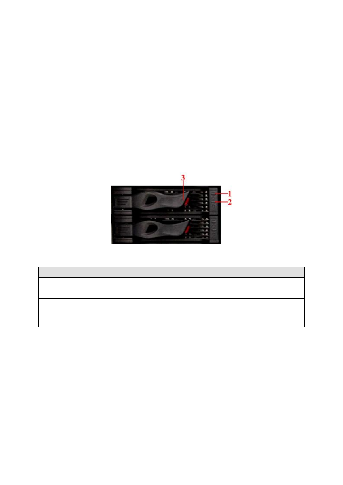
SN
Name
Function
1
HDD Power
indicator light
Green: The HDD is properly installed on the device and the power
is on.
Red: HDD malfunction.
2
HDD read-write
indicator light
Blue light flashes: Visiting HDD.
Red light flashes: The HDD indicator light function is on.
3
Handle of the HDD
box
To remove HDD box.
2 Installation
2.1 HDD Installation
Important
We STRONGLY recommend the enterprise class disk. We are not liable for any
problem (such as data loss) resulting from the HDD instability.
For one device, please use the HDDs of the same brand and of the same space.
For the single controller series product, it supports SAS HDD, SATA HDD.
For the dual controller series product, it supports SAS HDD only.
Put the HDD to the HDD box and fix the screws. Insert the HDD box to the slot at the front panel.
See Figure 2-1.
Figure 2-1
2.2 Remove HDD
HDD as a storage media, it saves important data. Please avoid frequently remove
operation in case it may result in data loss.
Usually you can remove HDD when there is no power connection or system is shut down.
Do not remove HDD after system boots up or it is working. Please refer to the appendix 6 for
detailed hot swap information.
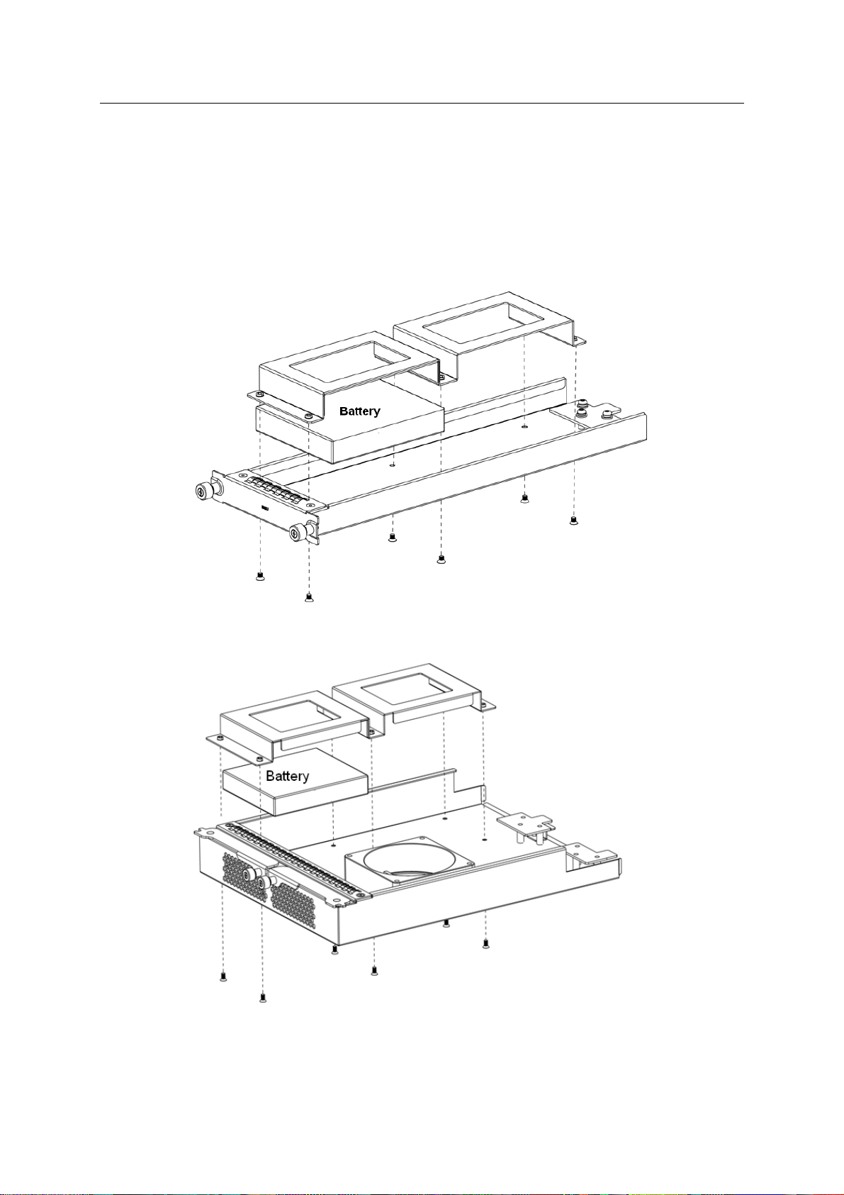
2.3 Battery Installation
Page 38
ESS Series User’s Manual
29
Please follow the steps listed below to install the battery. See Figure 2-2 (16-HDD series) and
Figure 2-3 (24-HDD series).
a) Take the battery&fan box from the device and then use the screwdriver to remove the top
cover of the battery box.
b) Take out the battery from the accessories’ bag and then insert to the battery box. Connect
the battery to the power socket.
c) Fix the top cover of the battery box and then secure the screws.
d) Insert the battery box to the device and then secure firmly.
Figure 2-2
Figure 2-3
Page 39

ESS Series User’s Manual
30
2.4 Boot up
Please boot up he disk array enclosure first if the host is connected to the disk array enclosure.
a) Connect the power cable to the system.
b) Press the device power on-off button at the rear panel to ON to boot up the system
(Please skip this step if there is no on-off button at the rear panel).
c) Press the power button at the front panel of the host.
2.5 Shut Down
Please shut down the host first if the host is connected to the disk array enclosure.
a) Login web interface. Please refer to chapter 3.1.
b) From System Management -> Shutdown.
c) Select option to shut down the system.
There are three options for you: shut down/restart/Force restart (For dual-controller series
product only). See Figure 2-4.
Or you can see these two shortcut buttons at the top right corner.
For the dual-controller series product, there are two controllers. Click the restart button; the two
controllers reboot one after the other. Click the force restart button, the two controllers reboot at
the same time.
Figure 2-4
Tips
In each interface, click the shut down button at the top right corner to shut down the device. See
Figure 2-4.
2.6 Network Setup
Page 40

ESS Series User’s Manual
31
Internet intelligent storage product default network setup is 192.168.0.111. It may be different
from you current network IP section. Please use the PC to login the WEB of the device and
change the host IP address so that it can connect to current network environment for future
operation and maintenance work.
Note
For the dual controller series product, the default IP is: is CTRL1: 192.168.0.111,
CTRL2: 192.168.0.121.
For ESS3116X series product, you do not need to check the management Ethernet
port or the data Ethernet port. You can just connect to one Ethernet port to connect to
the network.
a) Connect the PC to the management network port (WEB port) via the network cable.
b) Change the PC IP address as: 192.168.0.XXX. Subnet mask: 255.255.0.0. Default
gateway: 192.168.0.1. See Figure 2-5.
Figure 2-5
c) Open IE browser, input http://192.168.0.111(default IP address) you can see the login
interface. System user name is admin and password is 888888888888(16-digit).
d) In the main interface, from network to network and then click edit button . The edit
interface is shown as in Figure 2-6 .Here you can input your new IP address information.
Please input your IP address and gateway and then click save button.
Note
Login the WEB to change the network parameters of the management network port.
Page 41

ESS Series User’s Manual
32
Figure 2-6
e) Click Save button.
f) Open browser and then input new IP address such as http://172.12.5.576. You can see the
new IP is valid if you can login. You can go to the host Web interface or go to the In DOS
environment, input the command: ping 192.168.0.111 to test network connection is right or
not.
Page 42

ESS Series User’s Manual
33
3 Host Configuration
All the figures listed are based on the ESS5016S series product. Slight difference may be
found in the user interface if you are using other series products.
3.1 Login
Please refer to chapter 2.6 to connect host to the network and then follow the steps listed below
to login the WEB.
a) On windows OS, open IE browser and then input system IP address (Such as
http://172.12.5.5 if you device IP is 172.12.5.5.). Click Enter, you can see the following
interface. See Figure 3-1.
b) Please input user name and password to login. Default user name is admin and default
password is 888888888888.
c) Click Login button.
Important
The host series product has two types of network ports: Management port and data port.
Please make sure you have connected to the WEB port to login the WEB. Please refer
to chapter 1.3.2 for detailed information.
System supports various kinds of users such as admin, guest. Please refer to chapter
3.2.3 for detailed information.
Figure 3-1
3.2 System Management
In this interface, you can see the following nine parts.
System
Parameters
Account
Guide
Enclosure
Performance
Upgrade
Shut down
Version
3.2.1 System
Page 43

ESS Series User’s Manual
34
After you logged in, you can see system information interface. Or you can click system and then
select system information item to go to current interface.
For dual control series product, you can see the statuses of dual controllers.
Here you can see the following information:
Host name
System time
Start time
Device type
Software version
Hardware version
Power status
iSCSI status.
3.2.2 Parameters
After you logged in as the system administrator, click parameters button, you can see the
following interface. See Figure 3-2.
Device name: Set system name.
Device position: Input device position information for you reference.
Date: Set system date. Check the enable button to set.
Time: Set system time. Check the enable button to set.
Start Time Synchronize: Enable time synchronization function.
Server address: Set time server address.
Time interval: The interval for the time server synchronization operation.
Update now: Click it, system begins time synchronization immediately. You can see the
corresponding dialogue box if the synchronization operation failed.
Important
If it is your first time to go to the system, please set system date and time.
The time server IP and the device IP shall be in the same section if you want to use time
synchronization function.
Page 44

35
Figure 3-2
Type
User
Name
Default
Password
Rights
Note
Administrator
admin
888888888888
Edit/add/delete
This user can read, write
or delete all storage data
in current system. It can
configure the whole
system and set ordinary
user share directory
rights.
Ordinary
user
guest
666666666666
Edit
It refers to all users
except admin. Ordinary
user (such as guest) can
modify its own password,
review and save itself
operation log, read and
write in the
corresponding folder.
Ordinary
user
ftpuser
111111111111
Edit
“ftpuser” has two IDs. It is
the ordinary system just
like the guest and it is
also the default FTP
service user.
Please note there is
only one FTP
user”ftpuser”.
ESS Series User’s Manual
3.2.3 Account
Click Account button, you can see the following interface. See Figure 3-3.
Here you can view system user information. You can add/edit/delete user.
Please refer to the following sheet for detailed information.
Page 45

36
Figure 3-3
Click here to logout current user and switch
account to login again.
ESS Series User’s Manual
3.2.3.1 Edit User
Click edit button of corresponding user, you can see the following interface. See Figure 3-4.
For the administrator, you do not need to input old password. You just input new password and
confirm, you can modify a user’s password.
For the ordinary user you need to input old password to confirm.
Click Save button system goes back to User interface. You can see the corresponding dialogue
box if the operation failed.
3.2.3.2 Add User
Note
System can only add ordinary user such as user01. It has the same rights as the guest.
Figure 3-4
Page 46

ESS Series User’s Manual
37
In Figure 3-3, click add button, you can see the following interface. See Figure 3-5.
After input new user information such as user name, user type, user type, please click save
button. System goes back to user management interface. Otherwise, you can see the
corresponding dialogue box.
Figure 3-5
3.2.3.3 Delete User
Login the system as the administrator, select the delete button after the corresponding user,
system pops up a dialogue box to remind you that you are going to delete a user. Click O.K
button, all the information of current user will be deleted completely. You cannot use it to login
and operate.
Important
System can not delete an account if it has been set as a valid share account.
3.2.4 Guide
After you logged in as the system administrator, from system to guide, you can go to Guide
interface. Guide function is to help you get familiar with this device as soon as possible. You can
follow the tip in each interface and then modify as you need. You can just click next button to go
on.
Please refer to chapter 4.1 for detailed information.
3.2.5 Enclosure
After you logged in as the system administrator, in Enclosure interface, you can view main host
and disk array enclosure information, temperature, power voltage status, fan status.
Here you can view disk array enclosure version if you want to update its software. You can also
go to this interface to check the update operation is successful or not. See Figure 3-6.
Please refer to the following sheet for detailed information.
Page 47

ESS Series User’s Manual
38
Status Prompt
Status Note
OK
The components are OK. No error available.
Critical
The components have serious error.
Noncritical
The components have general alarms.
Unrecoverable
The components have an error that can not be fixed.
Not installed
There is no component.
Unknown
The components have unknown error.
Not available
The components can not work.
No access allowed
Can not access the components.
3.2.6 Performance
After you logged in as the administrator, you can go to the performance interface to view host
CPU usage rate, memory usage rate, network usage rate and IO realtime data. See Figure 3-7.
Figure 3-6
Page 48

ESS Series User’s Manual
39
Figure 3-7
3.2.7 Upgrade
Important
Before you upgrade the system, please go to our official website to download the
latest version.
Before you upgrade, please stop iSCSI service and RAID synchronization.
The upgrade process may take a few minutes, please wait patiently. DO NOT TURN
OFF THE DEVICE OR UNPLUG THE POWER WIRE.
3.2.7.1 Upgrade main controller After you logged in as the system administrator, from system to upgrade, here you can see a system upgrade interface is shown as in Figure 3-8. Select device type (host/disk array enclosure) from the dropdown list. Click Browse button; select the applications you want to update. You can see system pops up a dialogue box for you to confirm update operation. Please click OK to continue. After upgrading, please reboot your system.
Tips
Go to the Enclosure interface to view the device information to check current version number.
You can see the upgrade is successful or not.
Page 49
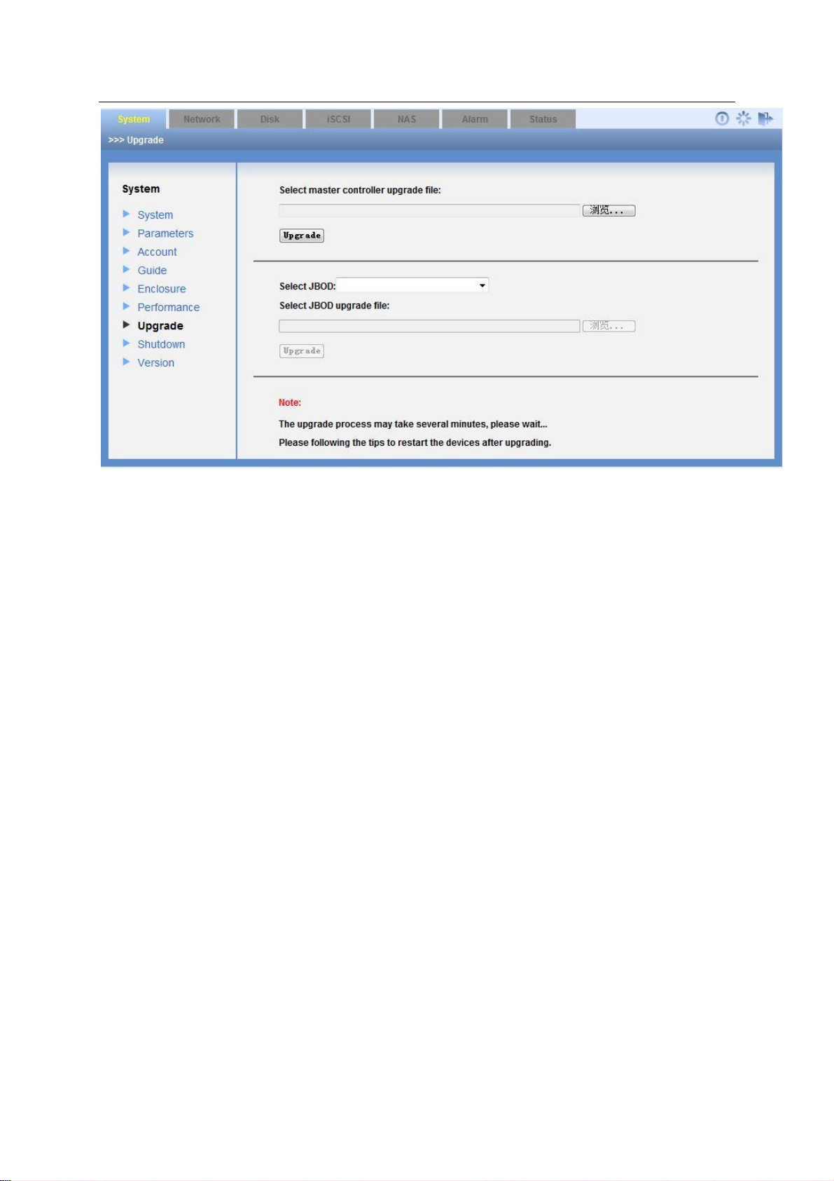
ESS Series User’s Manual
40
Figure 3-8
3.2.7.2 Upgrade disk array enclosure Administrator can select disk array enclosure from the dropdown list and upgrade the disk array enclosure. See Figure 3-8.
3.2.8 Shut down System
Click shut down system button; you can see the following interface. See Figure 3-9. Please note
the following interface is based on the dual-controller series product.
There are three options for you: shut down/restart/Force restart
Or you can see these two shortcut buttons at the top right corner.
For the dual-controller series product, there are two controllers. Click the restart button; the two
controllers reboot one after the other. Click the force restart button, the two controllers reboot at
the same time.
Page 50
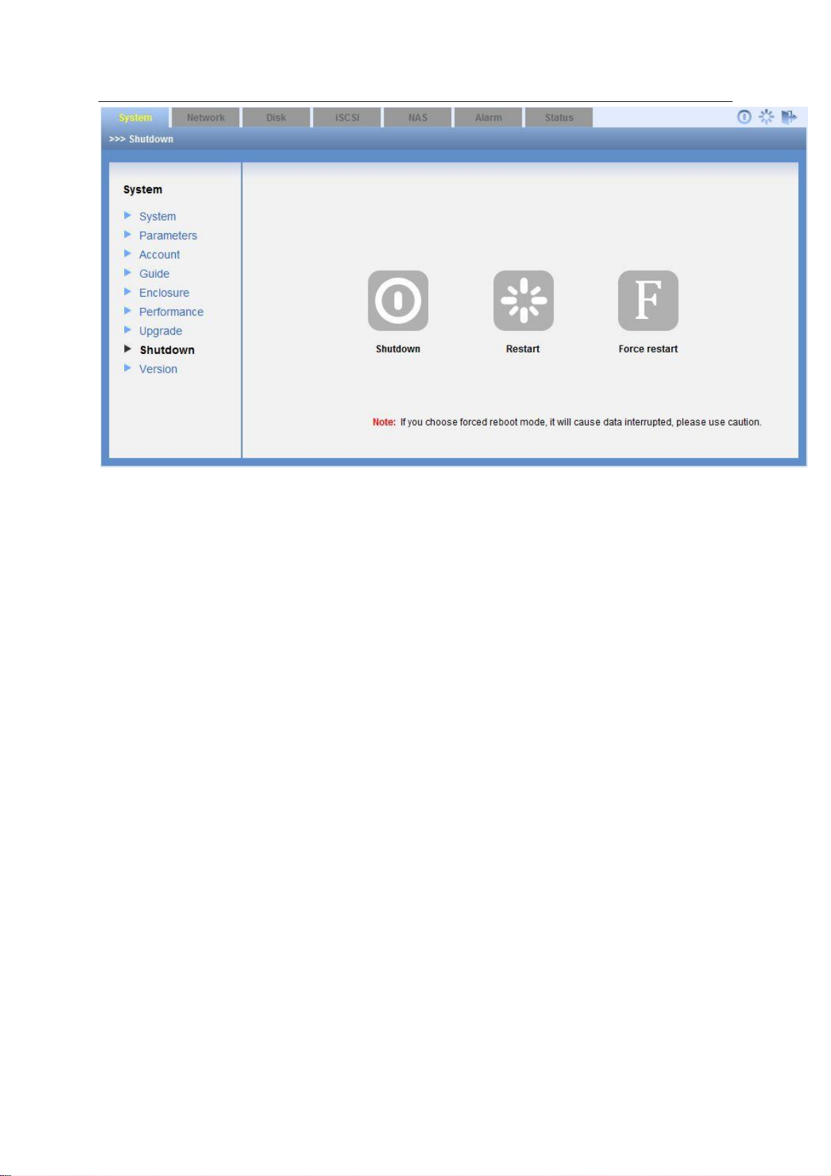
ESS Series User’s Manual
41
Figure 3-9
3.2.9 Version
In this interface, you can check the version information of each module.
3.3 Network Management
3.3.1 Network Configuration
Important
We STRONGLY recommend you set the management network port and data network port
to different network environments.
The data network ports shall be in 1000Mbps (or higher) environments.
After you logged in as the system administrator, click Network button, you can see the following
interface.
Here you can view current network card information. See Figure 3-10. Here you can also
view/edit/binding network adapter. The network port displayed here for reference only.
Network card name
IP address
Subnet mask
Default gateway
Mac address
Binding status
Member card
Page 51
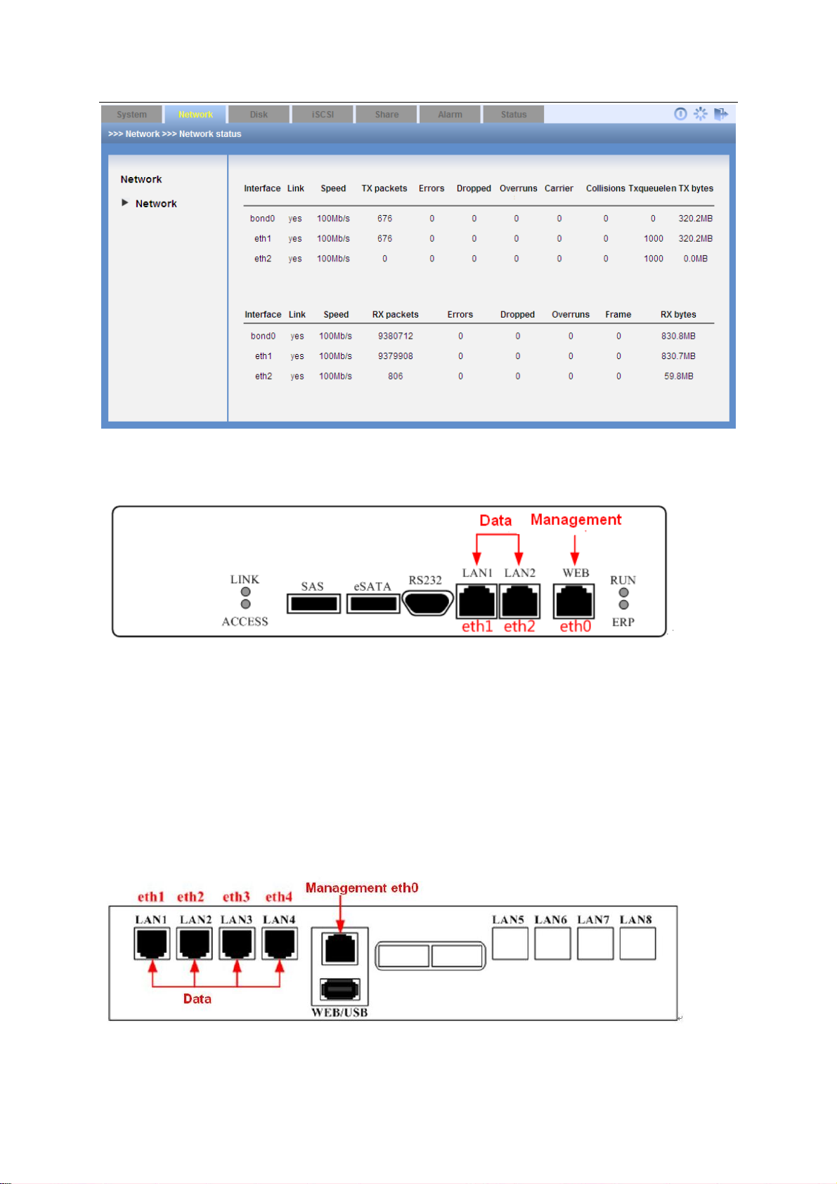
42
Figure 3-10
ESS Series User’s Manual
ESS2016X network port is shown as in Figure 3-11.
Figure 3-11
ESS3116X
For ESS3116X series product, you do not need to check the management Ethernet port or the
data Ethernet port. You can just connect to one Ethernet port to connect to the network.
ESS50XXS/ESS50XXS-R network port is shown as in Figure 3-12.
In ESS50XXS/ESS50XXS-R, the XX stands for the HDD amount, such as
ESS5016S/ESS5016S-R, ESS5024S/ESS5024S-R, or ESS5048S/ESS5048S-R.
Figure 3-12
Page 52

ESS Series User’s Manual
43
Network Port
Network Adapter
Function
Management Port
eth0
Use this port to login to the WEB interface.
Data Port
eth1/eth2/ eth3/
eth4
Use this port to read/write data.
Network Port
Network
Adapter
Function
Management Port
eth0
Use this port to login to the WEB interface.
Data Port
eth1, eth2,
eth3, eth4,
10G_1,
10G_2
Use this port to read/write data.
Please refer to the following sheet for detailed information.
ESS50XXD-R network port is shown as in Figure 3-13.
In ESS50XXD-R, the XX stands for the HDD amount, such as ESS5016D-R, ESS5024D-R.
Figure 3-13
Please refer to the following sheet for detailed information.
In this interface you can set device network adapter and display router in the LAN.
3.3.1.1 View NIC status
In Figure 3-10 click Status button, you can see network status interface. See Figure 3-14.
Note
The following figure for reference only.
Page 53
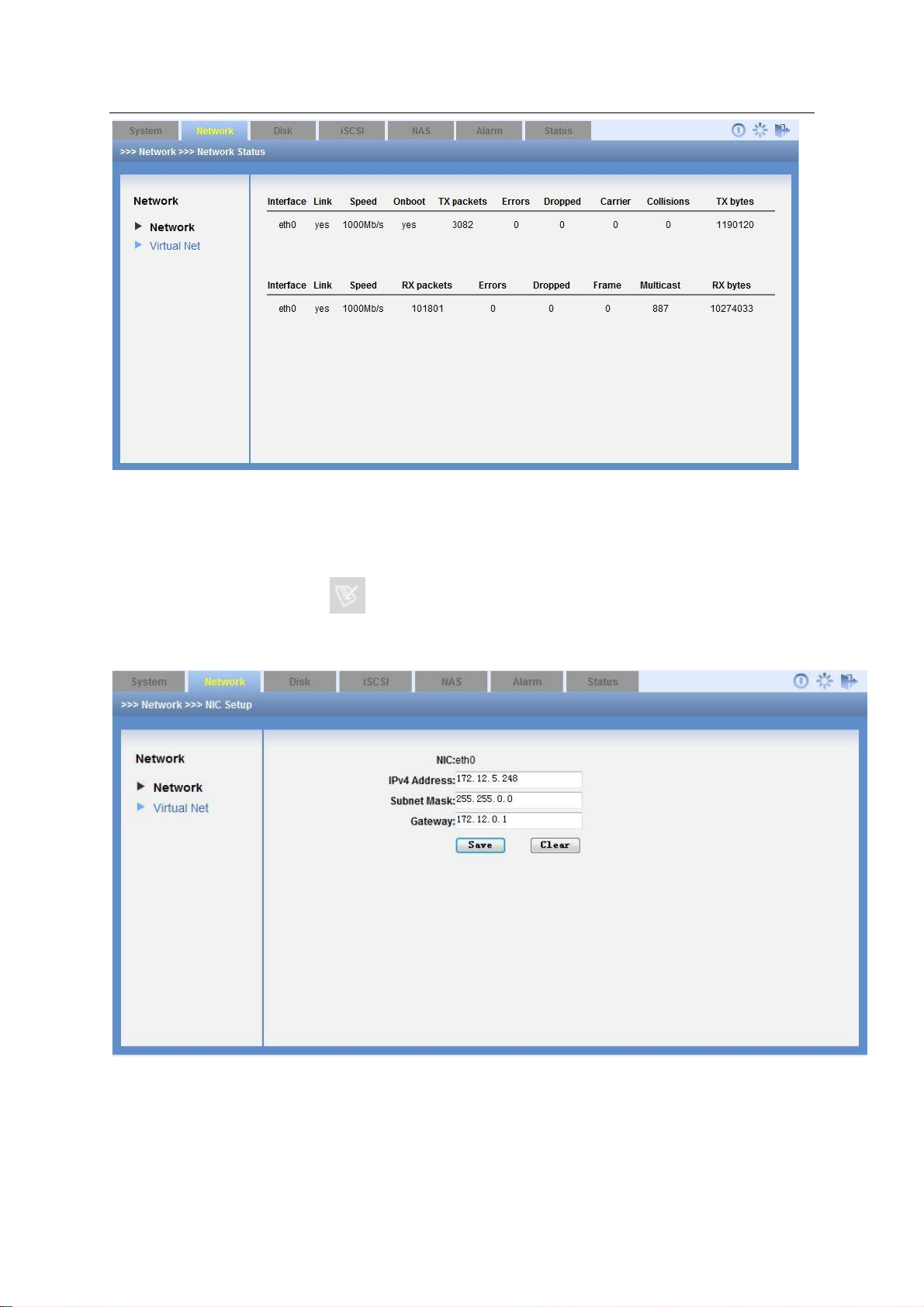
44
Figure 3-14
ESS Series User’s Manual
3.3.1.2 Edit network card
In Figure 3-10 click edit button , you can see the following interface. After your modification
(such as IP address, subnet mask, default gateway and etc), please click save button to exit. See
Figure 3-15.
Figure 3-15
3.3.1.3 Binding the network adapter
Click the binding button in Figure 3-10, you can go to the following interface. See Figure 3-16.
Page 54
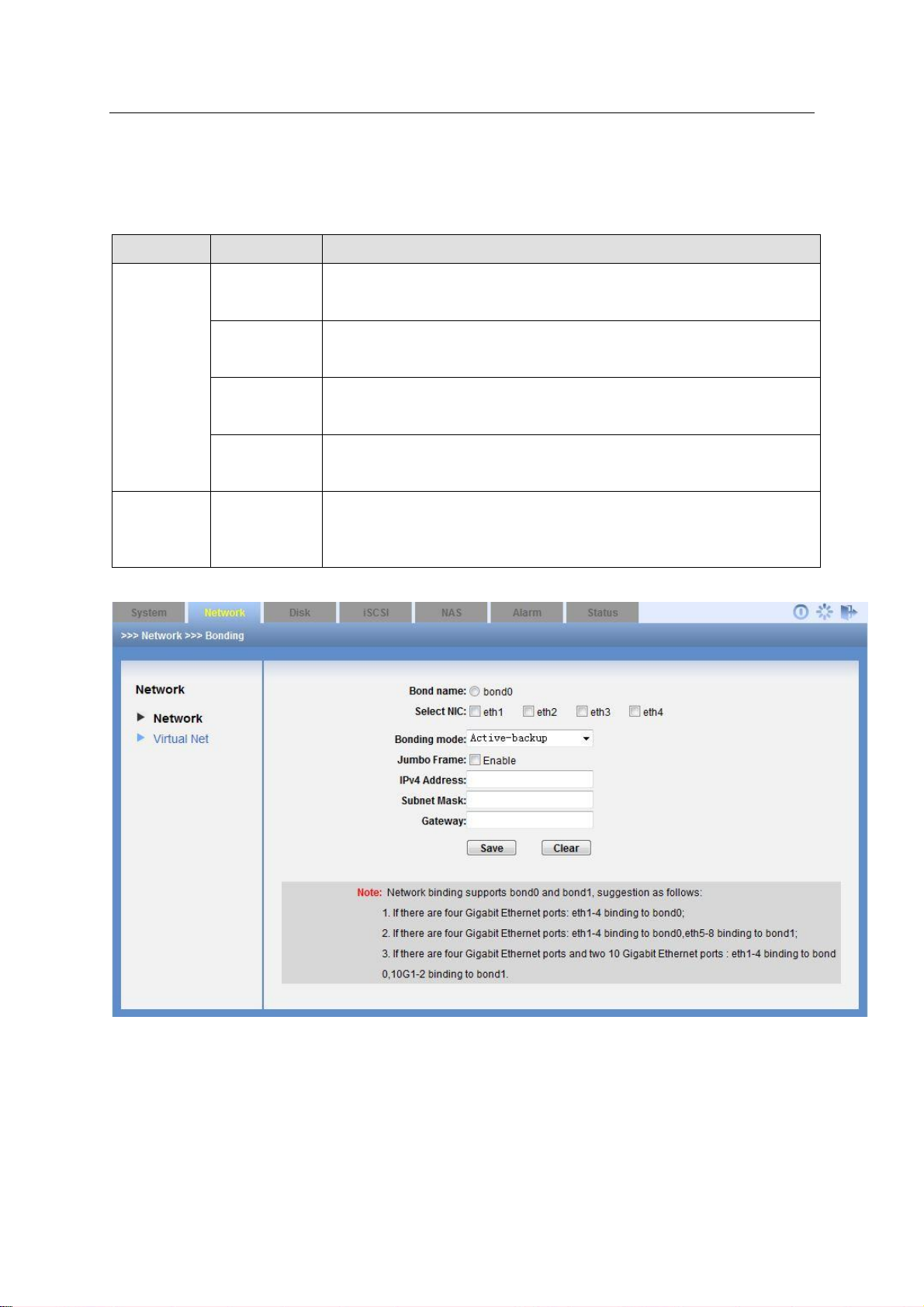
ESS Series User’s Manual
45
Parameter
Name
Note
Binding
Mode
Round mode
System sends out data packets by a sequence. This mode adds
bandwidth and support load balance and fault tolerance function. It
can switch the flow to the proper link once there is any problem.
Activebackup
One port is at active status (main port) and one port is at backup
mode. All flows are transmitted on the main link. The backup port
begins to transmit data once the main active port is malfunction.
LACP mode
It is to create an aggregation group. They share the same speed
and duplex setup. It allows several slaves to work on one active
object according to 802.3ad specifications.
Selfadaptive
mode
It has adapter transmission balance function. It has the receive
load balance function for IPV4 and there is no need to have a
switch.
Jumbo
Frame
Enable
Jumbo
Frame
It is to use jumbo frame to transmit data to enhance efficiency.
Note
Before you use this function, please makes sure you switch
supports this function.
This function allows you to binding two physical network adapters to one virtual adapter to
provide load balance or redundancy function to enhance bandwidth. In this mode, when one
adapter is malfunction, the other one can still work and has no effect on the system operation.
Please select two network adapters first and then input IP address, subnet mask and default
gateway. Click OK button you can complete the binding setup.
Figure 3-16
3.3.2 Virtual Network (For dual-controller series product only)
The virtual network is for NAS dual controller series product. The virtual IP can switch between
the two controllers and the setup is generally the same as the network setup. See Figure 3-17.
Page 55

46
Figure 3-17
ESS Series User’s Manual
3.4 Disk Management
Disk management is to display HDD physical information in the system. It includes: channel
number, disk space, disk status, RAID group name, usage status, disk No.
3.4.1 Disk Information
Click disk button, you can see the following interface. See Figure 3-18. The disk amount
displayed here for reference only.
Here you can review the following information.
Serial number
Channel number
Disk Name
Space
Status
Group name
Using status
Type
Note
From the dropdown list, you can view disk array enclosure HDD information.
For different series product, the HDD amount may vary. The following figure for reference
only.
Page 56
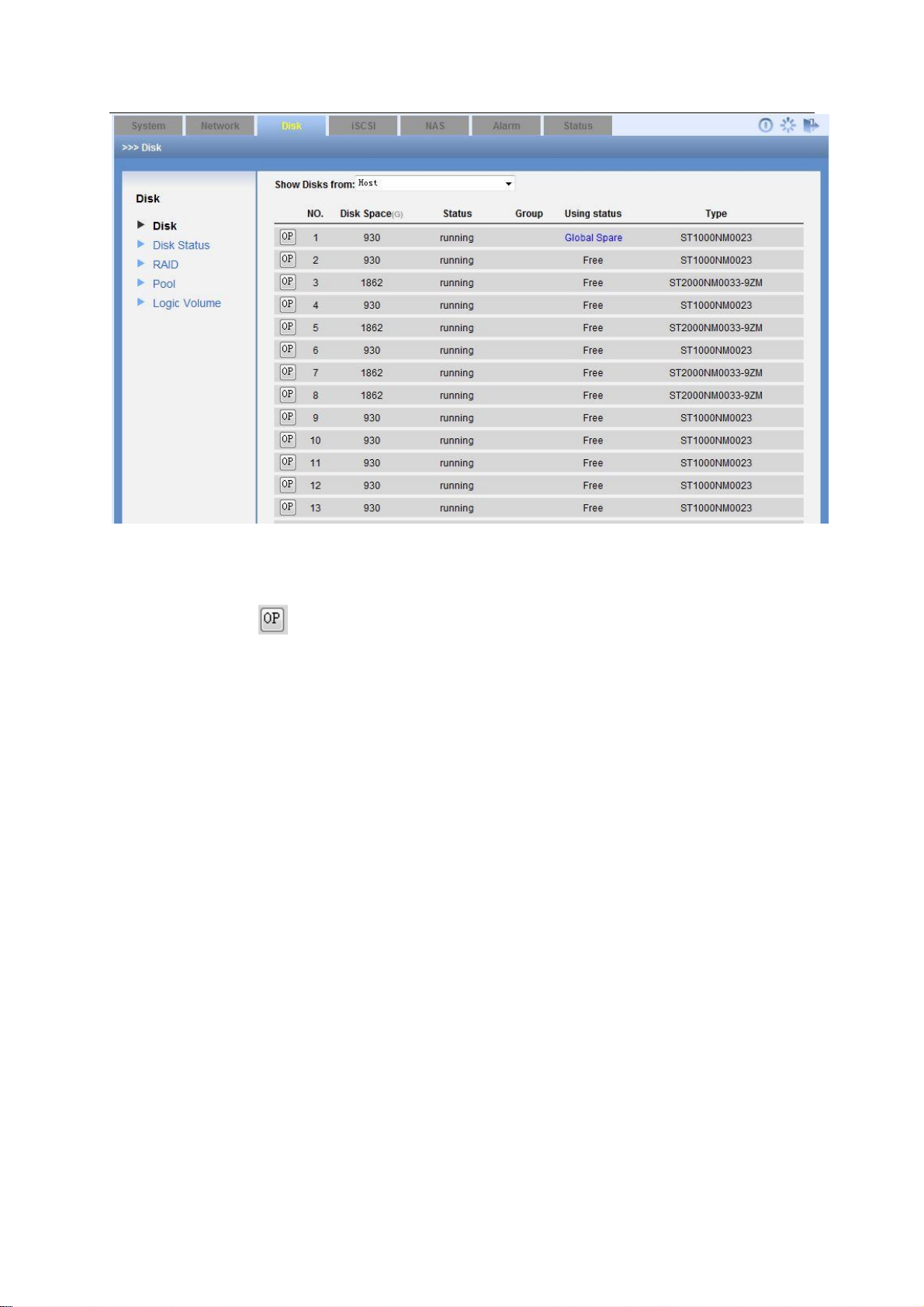
ESS Series User’s Manual
47
Figure 3-18
3.4.1.1 Enable disk indicator light
In Figure 3-18, click to enable HDD indicator light, you can turn on the corresponding HDD
indicator light. .
3.4.1.2 Initialization Disk initialization has great effect on the data security. Please think twice before you use.
3.4.1.3 Add hotspare disk This series product support global hotspare disk. That is to say, the whole RAID groups share hotspare disk. It only occupies the physical disk space when it is running. When any disk of the RAID group is malfunction, the hotspare disk can automatically replace it. In Figure 3-18, click add hot swap disk button, you can see an interface is shown as in Figure 3-19. Here you can view idle disk list. You can click the select button to select the hot spare disk. Then you can click save button to exit.
Note
One device can max have four hotspare disks.
The hotspare disk on the host can not replace the malfunction disk function from the
connected disk array enclosure and vice versa.
Page 57
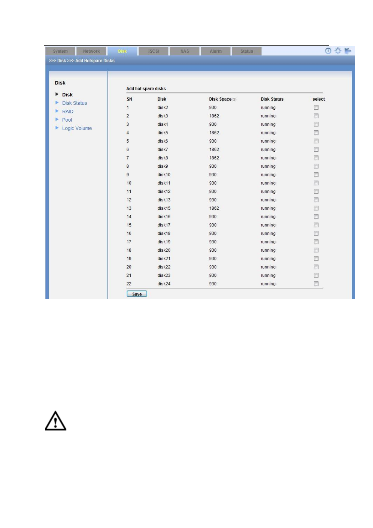
ESS Series User’s Manual
48
Figure 3-19
3.4.1.4 Remove hotspare disk In Figure 3-18, select a disk and then click remove hotspare disk button. Click save button to delete it from the hotspare disk list and its status becomes idle.
3.4.1.5 Enable MAID2.0 In Figure 3-18, select a disk and then click Enable MAID2.0 (massive array of idle disks) button, you can enable hibernation function. See Figure 3-20. This function allows the disk to stop working if there is no read/write function after a specified time. It is to save power consumption and enhance life span.
Important
Please disable MAID function if the disk read-write operation is frequent. Otherwise, the
frequent boot up and stop operation is going to reduce disk life span.
Page 58

ESS Series User’s Manual
49
Figure 3-20
3.4.2 Disk Status
In this interface, you can check the disk status of each channel and detailed SMART information.
S.M.A.R.T (Self-Monitoring, Analysis and Reporting Technology) technology is to provide disk
malfunction warning before the real problem occurs. It is to prompt user to replace disk or backup
disk data in case there is any risk of data loss.
Click details button, you can see system pops up a dialogue box for you to view the detailed disk
information.
Page 59

ESS Series User’s Manual
50
Status
Note
clean
The RAID group has completed the synchronization.
degraded
The RAID group is degrading now.
recovering
The RAID group is recovering now. You can view recovering
capacity percentage and synchronization speed on the [].
resyncing
The RAID group is synchronizing now. You can view recovering
capacity percentage and synchronization speed on the [].
Do not use when RAID group is synchronizing. That is to say,
do not create storage pool and share directory.
inactive
Current RAID device is null.
active
Current RAID device is available.
Figure 3-21
3.4.3 RAID Configuration
Click RAID button, you can see an interface is shown as in Figure 3-22.
If the logged in account is ordinary user, you can only view the RAID information.
If the logged in account is administrator, you can view/edit/delete/add RAID group.
Tips
Go to Appendix A for detailed RAID information.
Page 60

ESS Series User’s Manual
51
RAID Type
Disk Needed
RAID0/JBOD
At least 2 disks.
RAID1
Only 2 disks.
RAID3
At least 3 disks.
RAID10
At least 4 disks.
RAID5
At least 3 disks. Usually we recommend the RAID4 includes 4
to 6 disks.
RAID6
At least 4 disks.
RAID50
At least 6 disks.
RAID60
At least 8 disks.
Figure 3-22
3.4.3.1 Add RAID configuration Click add button, you can see the following interface. In Figure 3-23, administrator can select RAID type (RAID0, RAID1, RAID5, RAID6, and JBOD) and then select the member disk. The damaged or used disks will not be listed in current interface. Please click save button to finish the operation. You can see the disk array enclosure from the location dropdown list if you have connected to the disk array enclosure. Otherwise, you can not see this item.
About chunk depth
Chunk depth setup here can affect device storage capability. Please refer to your technical
engineer first and then input the proper value you calculated according to actual I/O data. The
default value is 16.
Please refer to the following sheet for detailed information.
Page 61

ESS Series User’s Manual
52
Figure 3-23
3.4.3.2 Remove RAID configuration The remove operation consists of the following three situations. You can refer to Figure 3-22. If current RAID is free (there is no storage pool, you can just click remove button to remove it
directly.
If current RAID has been used (there is a storage pool), but there is no share directory. Click
remove button, you can see system pops up a dialogue to warn you. You need to remove
storage pool and then remove the RAID group.
If current RAID has been used (there is a storage pool) and there is a share directory. Click
remove button, you can see system pops up a dialogue box to warn you. You need to delete
share directory and storage pool first, and then you can remove the RAID group.
3.4.3.3 Set special hotspare disk
Click , select set special hotspare disk, you can add or delete special hotspare disk. See
Figure 3-24.
Page 62

ESS Series User’s Manual
53
Figure 3-24
3.4.4 Pool Configuration
After you logged in the system as the administrator and go to the Pool interface, you can see the
following interface. See Figure 3-25.
Here you can view the following information:
Pool name
Member device.
Total space (G)
Used space.
Disk array enclosure
Edit
Delete
Page 63

ESS Series User’s Manual
54
Figure 3-25
3.4.4.1 Remove Pool The remove operation consists of the following two situations. You can refer to Figure 3-25.
Click remove button if there is no share directory in the storage pool.
You can see a dialogue box pops up if there is a share directory. You need to delete share
directory first and then remove the storage pool.
3.4.4.2 Add Pool In Figure 3-25, click add button, you can see the following interface. See Figure 3-26. Here you can select RAID device (RAID0, RAID1, RAID5, RAID6, and JBOD), single disk (such as disk1) to create a storage pool. Click save button after creating storage pool device. You can see the disk array enclosure from the location dropdown list if you have connected to the disk array enclosure. Otherwise, you can not see this item.
Page 64

ESS Series User’s Manual
55
Figure 3-26
3.4.5 Logic Volume
After you login the WEB as the administrator, you can add/delete logic volume or add space. See
Figure 3-27.
Figure 3-27
3.4.5.1 Delete user volume It is for you to delete the user volume.
3.4.5.2 Add user volume It is for you to add user volume, please input user storage pool, and set space. See Figure 3-28.
Figure 3-28
Page 65
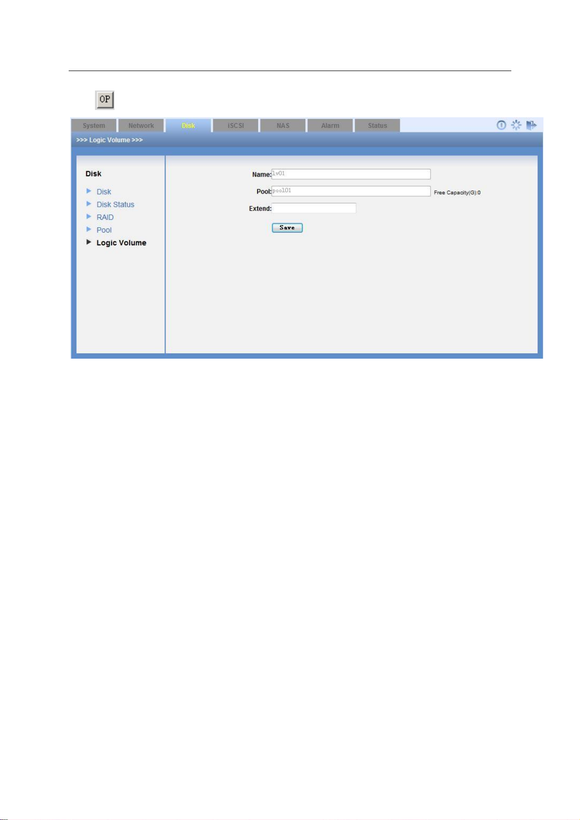
ESS Series User’s Manual
56
3.4.5.3 Extend user volume
Click and then select extend user volume; you can add its space. See Figure 3-29.
Figure 3-29
3.5 iSCSI Management
iSCSI is to provide iSCSI share service for you.
3.5.1 Add iSCSI share configuration
Note
Before you add iSCSI, please create user volume first. Please refer to chapter 3.4.5 for detailed
information.
The interface is shown as in Figure 3-30.
Here you need to configure the following four items when you adding iSCSI share.
Target (mapping) name: it is a part of iSCSI share device name. It is easy for you to
recognize the iSCSI device.
Logic volume: It is to set the shared user volume when you create the iSCSI.
Block size: It is to set the shared storage space size.
Set space: Here you can set device size. Unit is G.
Device: There are two options: Host/disk array enclosure.
Cache type: There are two options: write-back, write-through. You can refer to the contents
at the bottom of the interface for detailed information.
Location: Select host/disk array enclosure from the dropdown list.
CHAP user: You select valid user name and password when system loads iSCSI share.
Refer to chapter 4.2 and Appendix C for detailed information.
Select a valid user: when loading an iSCSI share you need to input a valid user name
and password.
Page 66

ESS Series User’s Manual
57
Do not select a valid user: when loading an iSCSI share you do not need to input a valid
user name and password.
Figure 3-30
3.5.2 Edit iSCSI share
Click Edit button in Figure 3-30, you can go to the following interface. Here you can edit
parameters such as CHAP user information. See Figure 3-31.
Page 67

ESS Series User’s Manual
58
Share Type
Status
Parameter
Note
SAMBA share
cifs
SAMBA is to provide share service for Windows
user.
NFS share
nfs
NFS is to provide share service for Linux user.
FTP share
ftp
FTP is to provide share service for both Windows
and Linux users.
Note
If share status is disabled, it is not in share mode.
Figure 3-31
3.5.3 Delete iSCSI share configuration
In iSCSI main interface (See Figure 3-30), you can select an iSCSI share device and then click
delete button.
3.6 NAS Management
3.6.1 Share configuration
The share interface is to display SAMBA, NFS and FTP share information. Here you can also
add, edit or delete share directory.
Please refer to the following sheet for detailed information.
3.6.1.1 Add share directory
Page 68
ESS Series User’s Manual
59
Name
Name
Note
Share directory
setup
Logic volume
System administrator can select a logic volume
from the user menu list.
NAS
directory
It is the share directory name you created on the
logic volume.
Share
description
It is to input description information of current
directory (optional).
SAMBA setup
Share
Enable SAMBA share and then disable NFS and
FTP share,
Valid user
Only the selected user can access the share
directory. If there is no valid user, all users can
access the share directory.
NFS setup
Share
Enable NFS share and then disable SAMBA and
FTP share,
Valid IP
The user IP address or subnet mask that can
access the share directory. The IP address can be
a valid IP address or a valid IP segment.
If there is valid IP, only user of valid IP (such as
10.6.5.77) can access NFS share. The user
right is read/write.
If there is valid IP section, only Linux users of
the valid IP section (such as 10.6.0.0—
10.6.255.255) can access NFS share directory
and the right is read/write.
Note
16 and 32 are just two ways to display subnet
mask. “32” stands for 255.255.255.255 and “16”
stands for 225.255.0.0.
FTP setup
Share
Enable FTP share and then disable NFS and
SAMBA share.
Valid user
Select valid user. Only ftpuser can access FTP
share directory if you do not select a valid user.
Note
For the FTP function, the user ftpuser has super
user function. It can manage all directories and
files the ftp user created. Other users do not
have this function; they can only manage their
own created directories and files.
Important
Before you add a share directory, please create a logic volume first.
Login as the administrator, go to the share manage interface click add button, you can see an
interface is shown as in Figure 3-32. It is an interface for you to add share directory.
Please note you can only select one item from the SAMBA/NFS/FTP.
Please refer to the following sheet for detailed information.
Page 69

ESS Series User’s Manual
60
Figure 3-32
3.6.1.2 Fix share directory If the share directory description is shown as “File system mount failed”, you can click the fix
button to fix the share directory.
3.6.1.3 Delete share directory In share configuration interface, select the item from the share list and then click corresponding delete button. The folder will be deleted permanently.
3.6.2 FTP Configuration
Login as the administrator, click FTP configuration, the interface is shown as in Figure 3-33.
Here you can view FTP configuration information. You can set FTP share directory, delete FTP
share directory.
In Figure 3-33, you can see the following information:
Transmission speed (unit: KB):It is the max transmission speed of the FTP share If the
speed is 1000KB, it means the transmission speed of each connection shall be less than
1000KB. When transmission speed is 0KB, it stands for there is no transmission limit.
Connection amount of each IP: The max FTP access amount of each user (By IP address).
Total connection amount: The max FTP access amount of all users (By IP address).
Page 70

61
Figure 3-33
Parameter
Name
Note
Buzzer
Buzzer enable
Enable/disable buzzer.
Email Alarm
Email alarm
enable
Enable/disable email alarm.
SMTP server IP
address
Input sender SMTP server IP address.
Port
Default port number is 25.
ESS Series User’s Manual
3.7 Alarm Management
From alarm management->alarm setup, you can go to the following interface. Here is for you to
set buzzer/email function. See Figure 3-34.
Please input the corresponding parameter here and click Save button. Click Test button, the
sender will send out the test email to the receiver. You can see the corresponding dialogue box if
the test is successful. At the same time, the receiver can get the test email. Otherwise, system
returns error information.
When enclosure manager detects any abnormal event, or the RAID group is inactive, you can
receive an email if you have enabled email alarm function. Or you can hear audio from the
buzzer if you have enable buzzer alarm function.
Support the SNMP protocol software connections from the third party. The search contents
include system information, disk information, RAID information and etc. TRAP alarm information
includes disk insert and remove, RAID degrade or failure. You can download Mib file for the
SNMP client 2nd development.
Note
Before you test, please save your current email test parameters. Otherwise, system
returns error information.
Page 71
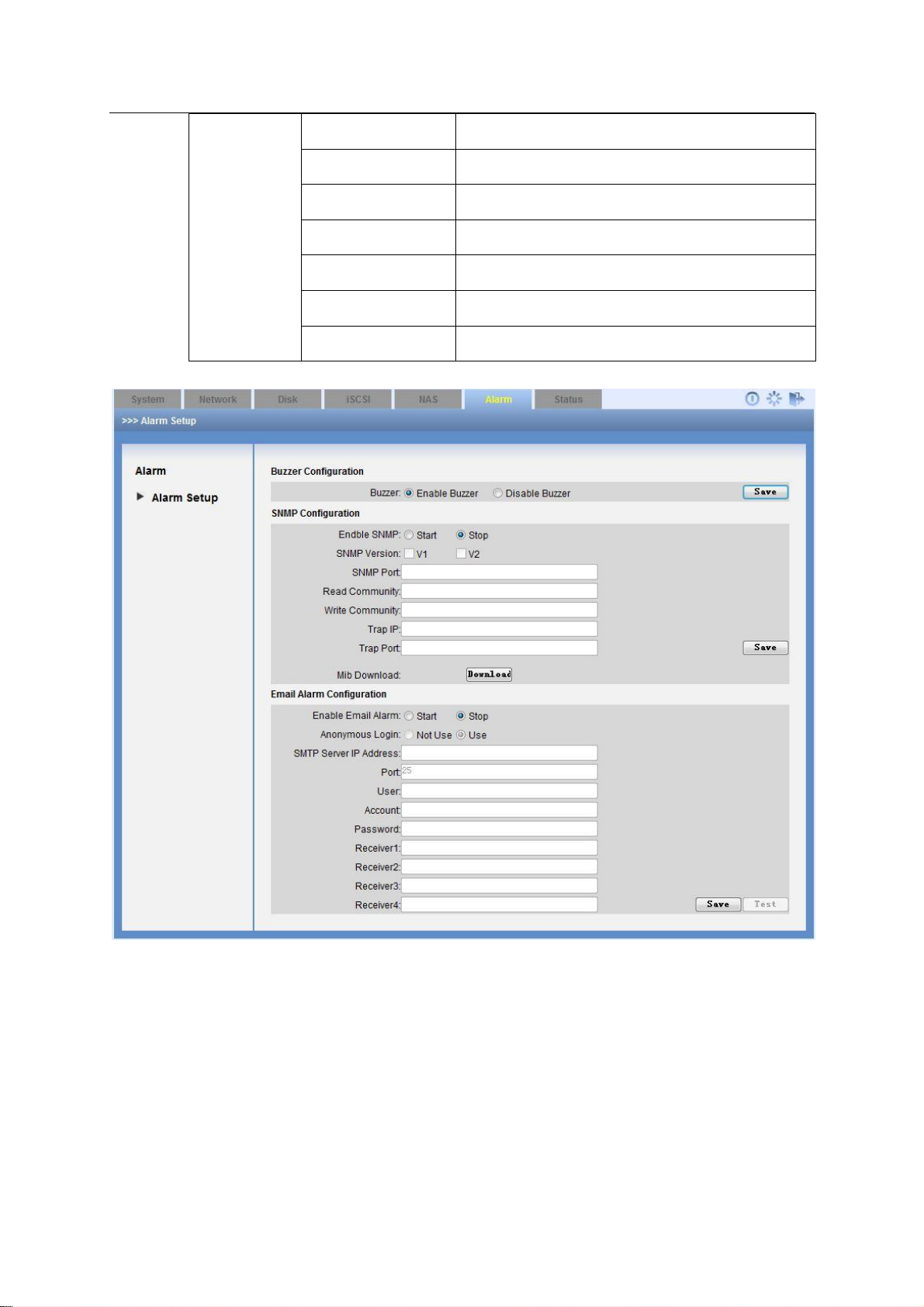
ESS Series User’s Manual
62
User name
SMTP server sender account.
Account
SMTP server sender email account.
Password
SMTP server sender email password.
Receiver1
Input receiver email address.
Receiver 2
Input receiver email address.
Receiver 3
Input receiver email address.
Receiver 4
Input receiver email address.
3.8 Status Management
Status management is to view system log, system status and system upgrade.
3.8.1 Log Review
Click log view button, you can see the following interface. See Figure 3-35.
Log search consists of three modes:
Search all logs: click search button you can see all logs.
Figure 3-34
Page 72

ESS Series User’s Manual
63
Search the recent logs: input log amount you want to view in the () and then click search
button. Please note system take current time as starting time.
Search the log during the specific time period. You can input a time period in the interface to
search the log you want to view.
Search by type: It includes info/alarm/error. Please note ESS2016X does not support this
type.
Search by key words: Input key words to search.
Figure 3-35
Click export button, system pops up the following interface. See Figure 3-36.
Click save button and specify the path. You can download the logs to your local PC.
Please note administrator can export and review all logs, ordinary user can only review and
export the operation logs of his own.
Max log amount is 1000. System will automatically overwrite the previous log files once the log
exceeds 1000 items.
Note
The log files have been encrypted. You can not open by yourself. If the device is abnormal, you
can export the log files such as log_packet.tar.gz.encod to your local retailer or your service
engineer for help.
Page 73
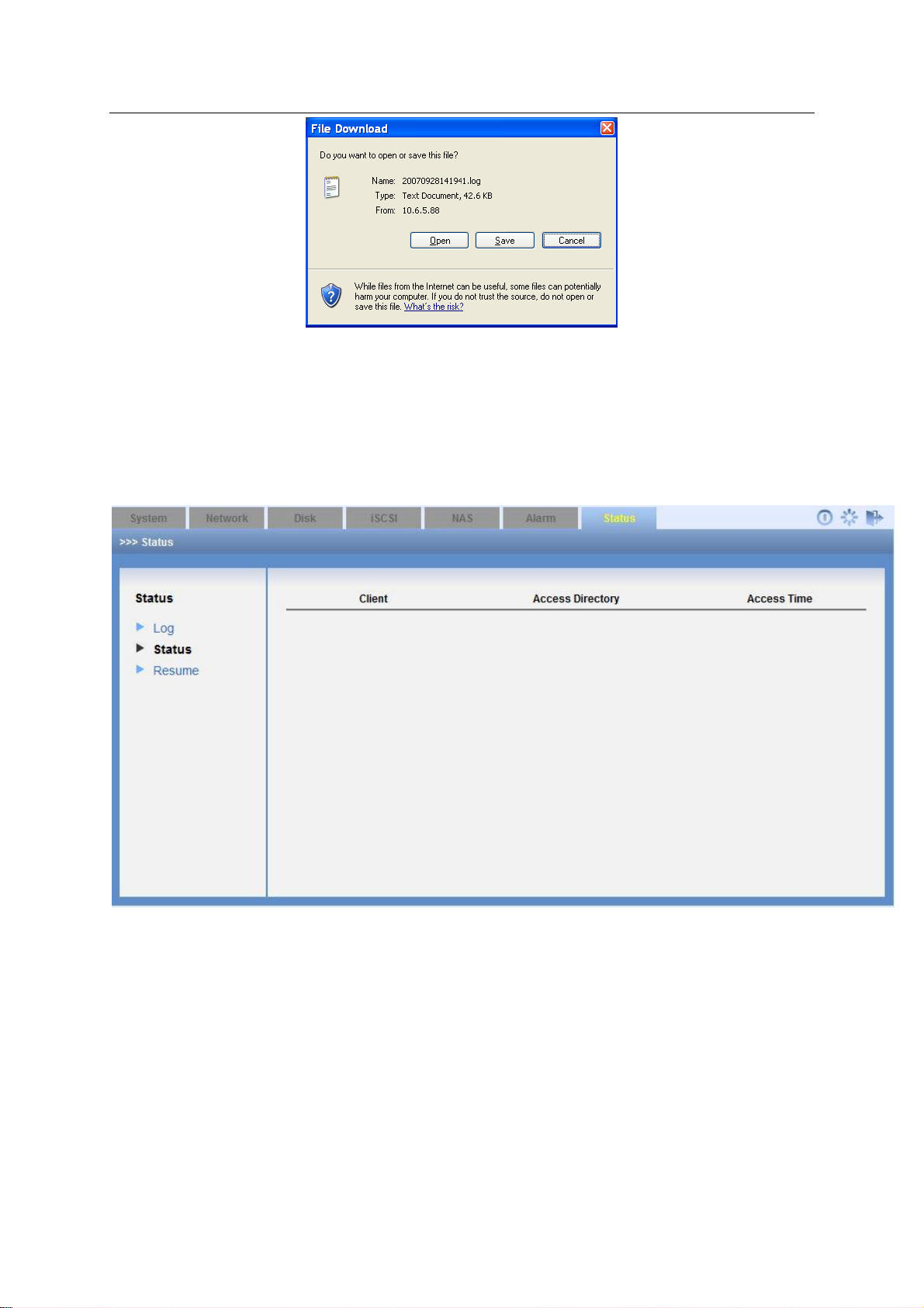
ESS Series User’s Manual
64
Figure 3-36
3.8.2 Service Status
Click service status, you can see an interface is shown as in Figure 3-37.
Client-end: It is to display current SAMBA share directory PC name and its IP address.
Access directory: Current SAMBA share directory name.
Access time: Visit time.
Figure 3-37
3.8.3 Resume
Resume interface is shown as in Figure 3-38.
After you logged in the system as the administrator, there are two options: export
configuration/resume factory default setup.
This function allows you to export the configuration file (such as SysConflog_packet.tar.gz.encode) and then send it back to our engineer to analyze the error
reason.
Page 74

65
Figure 3-38
Parameter Name
Note
Resume all setup
Restore all items to factory default setup.
Resume account setup
Except the system default four users, rest accounts
will be deleted.
Resume network setup
Restore network items to factory default setup.
Resume NAS setup
Delete all NAS share.
Resume iSCSI setup
Delete all ISCSI share.
ESS Series User’s Manual
Please refer to the following sheet for detailed information.
Page 75

ESS Series User’s Manual
66
4 General Operation
4.1 Quick Guide
If it is your first time to use this device, you can follow the steps listed below.
Before the quick guide operation, please make sure:
There are no free slots on the front panel. All slots are installed with the free disks.
System is going to create 3 RAID5 groups. The last disk is the global hot spare disk.
You can refer to chapter 4.2 to create share directory directly if it is necessary.
4.2 Create Share Directory
4.2.1 Create SAMBA Share
Please refer to the following flow chart for detailed information.
a) Please refer to chapter 3.1 to login the WEB interface.
b) Refer to chapter 3.2.3.2 to create system user and the type shall be “SAMBA/NFS/FTP”.
c) Refer to chapter 3.4.3 to add RAID group.
d) Refer to chapter 3.4.4 to add storage pool.
e) Refer to chapter 3.4.5 to add user volume.
f) Refer to chapter 3.6.1 to add SMABA share directory.
i. Select the storage pool on the step 4.
ii. Enable SAMBA share function and disable NFS and FTP share mode
iii. Select valid user.
g) Click OK button.
After you created share mode, please refer to chapter 4.3.1 to access the contents of the
SAMBA share directory.
4.2.2 Create NFS Share
You can refer to the steps in chapter 4.2.1 to create NFS share directory. There are slightly
differences on the share directory setup and enable share service.
Please refer to chapter 4.2.1 to quickly create NFS share.
Refer to chapter 3.6.1 to enable NFS share mode and disable SAMBA and FTP share mode.
4.2.3 Create FTP Share
Generally speaking, the following flow chart is the same as the NAS share/SAMBA share. Here
we are going to introduce share setup and FTP setup.
Page 76

ESS Series User’s Manual
67
a) Refer to chapter 4.2.1 to complete the admin login, create RAID device and create
storage pool operation.
b) Refer to chapter 3.6.1 to enable FTP service and disable SAMBA/NFS share service.
c) Refer to chapter 3.6.2 to view FTP setup information.
4.2.4 Create iSCSI share
Please refer to the following flow chart for detailed information.
From the above flow chart, you can see the first four steps are the same as the SAMBA share
creation. You can refer to chapter 4.2.1 for detailed information.
a) Admin logs in the system. Refer to chapter 3.1.
b) Create RAID group (optional). Refer to chapter 3.4.3.
c) Create and set storage pool if you have added the RAID group in the previous step.
Refer to chapter 3.4.4.
d) Add user volume. Refer to chapter 3.4.5.
e) Refer to chapter 3.5 to add iSCSI share.
4.3 Access Share Directory
4.3.1 Access SAMBA Share Directory
You can refer to the steps listed below to access SAMBA share directory.
Input ESS product IP address on the browser such as \\10.10.6.83.
Input user name or password on the long-in interface. See Figure 4-1.
Figure 4-1
After you connected the ESS product to the central management software platform, you can view
the SAMBA directory of the ESS product as one network disk and map it to the local disk. Please
follow the steps listed below.
Page 77

ESS Series User’s Manual
68
Please access SAMAB share directory. See Figure 4-1.
Right click mouse and then select Map Network Drive. See Figure 4-2.
Figure 4-2
Select map network drive name. See Figure 4-3.
Figure 4-3
Go to local PC, double click My Computer, you can see an interface shown as in Figure 4-4.
Page 78

ESS Series User’s Manual
69
Figure 4-4
4.3.2 Access NFS Share Directory
On Linux OS, use command to mount the NFS share directory to one of the directory and access
the directory.
Before the operation, please make sure the NFS service of the Linux user platform and the
ESS3166X series product are both enabled.
Please refer to the following contents for detailed mount command (Linux user-end):
mount –t nfs 10.12.5.14:/mnt/pool1/DVRch2/DVRch2 /home/user
10.12.5.14: ESS3116 series product IP address;
/mnt/pool1/DVRch2/DVRch2: ESS3116 series product NFS share
directory;/home/user: Mount directory of the Linux user-end.
After you complete the NFS mount, please use command to unmount.
umount /home/user
/home/user: Mount directory of the Linux user-end.
4.3.3 Access FTP Share Directory
There are two ways for you to access FTP share directory. Usually we recommend FTP software
to access FTP share directory.
Use FTP software to access
Please install FTP software (such as LeapFTP, flashfxp) on your PC to realize FTP share.
Use IE browser to access.
Open your browser and then input ESS3116 series product IP address such as ftp://172.12.5.5.
Input valid user name, password on the login interface. System default FTP user name is ftpuser
and password is 111111111111.
Page 79

70
Figure 4-5
4.3.4 Access iSCSI Share Directory
Please refer to Appendix B for detailed information.
ESS Series User’s Manual
Page 80
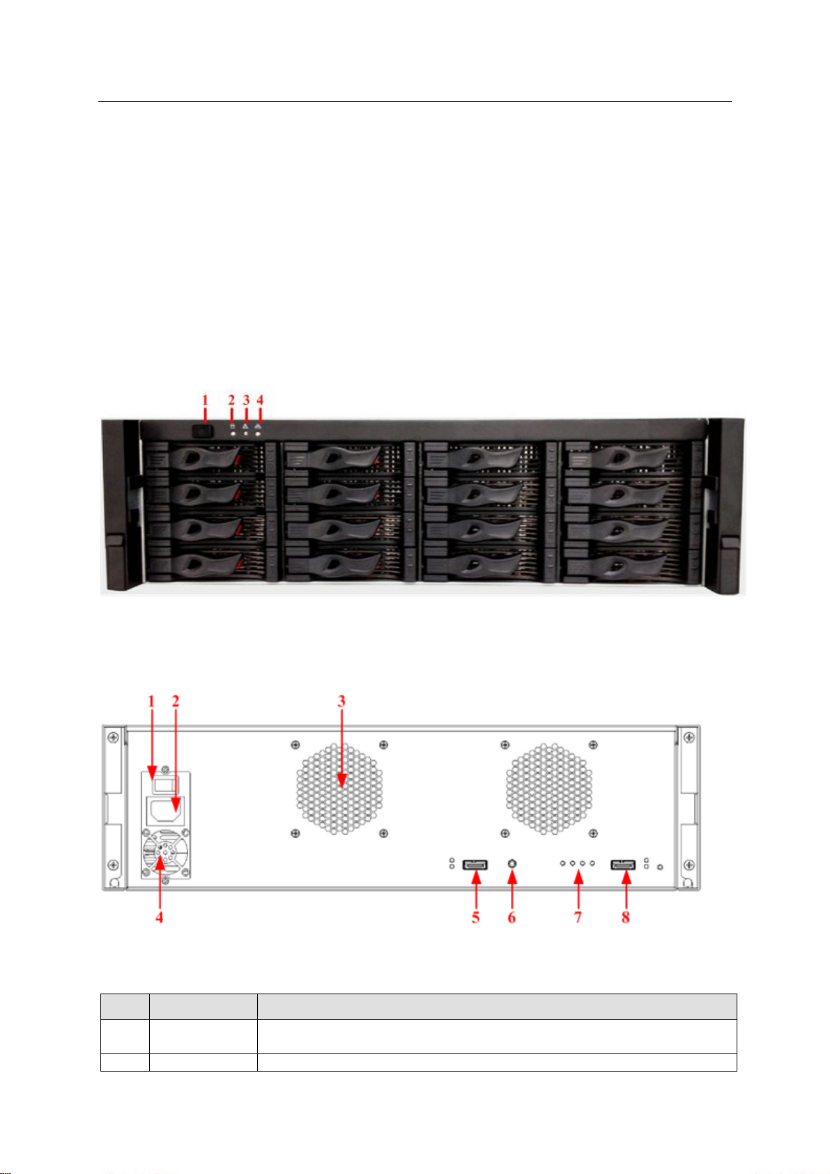
ESS Series User’s Manual
71
SN
Port
Port Introduction
1
Power on-off
button
Connect or cut off the device power.
2
Power Port
Connect to AC power supplying.
5 Disk Array Enclosure
Disk array enclosure is to extend the disk capacity extension of the internet intelligent storage
product.
5.1 HDD Installation
You can refer to chapter 2.1 to install HDD.
5.2 ESS2016X-J
5.2.1 Front Panel
The front panel is shown as below. See Figure 5-1.
Figure 5-1
5.2.2 Rear Panel
The rear panel is shown as in Figure 5-2.
Figure 5-2
Please refer to the following sheet for detailed information.
Page 81

ESS Series User’s Manual
72
3
Case fan
It is for case ventilation.
4
Power fan
It is for power ventilation
5
IN port
indicator light
LINK light: The light becomes on when the disk array enclosure is
connected to the host or the upper-level disk array enclosure.
ACCESS light: The light flashes when the host is visiting disk array
enclosure.
IN port
Connect IN port to the OUT port of the host or the upper-level disk
array enclosure. Access the HDD of the disk array enclosure via the IN
port.
6
RS232 port
It is to debug device and login command interface.
Please refer to chapter 9 for detailed command operation information.
7
Indicator light
RUN light is on when the device is on and working properly.
M/S: main control light. The light is on when the device is running
properly. The light is off when there is abnormal situation.
ERR light is on when there is abnormal situation.
The ERR light is off when the device is working properly.
SPD light is on when the HDD accessing speed is abnormal.
SPD light is off when the HDD accessing speed is normal.
8
OUT port
Connect OUT port to the lower-level disk array enclosure to realize the
cascade connection.
OUT port
indicator light
Link light is on when the OUT port is connected a lower-level device.
Access light is on when there is data access on the OUT port.
5.2.3 Disk Array Enclosure Cascade Connection
When connect ESS2016X to ESS2016X-J, the interface is shown as below. See Figure 5-3.
Figure 5-3
Page 82
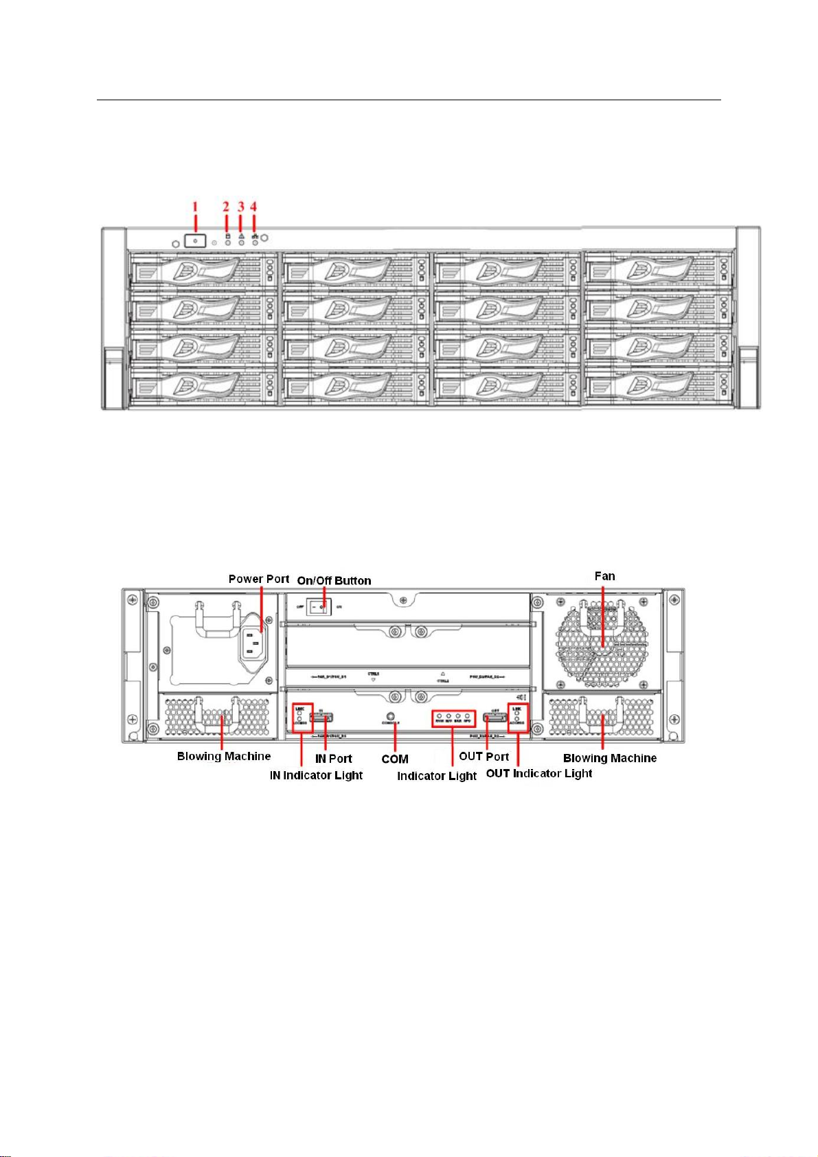
73
5.3 ESS3116X-J
5.3.1 Front Panel
The front panel is shown as below. See Figure 5-1.
ESS Series User’s Manual
Figure 5-4
5.3.2 Rear Panel
The rear panel has two types: single power and redundancy power. These two types have slight
difference on the power module and fan module. Please check carefully.
The single power mode rear panel is shown as below. See Figure 5-5.
Figure 5-5
The redundancy power series rear panel is shown as in Figure 5-6.
Page 83

ESS Series User’s Manual
74
Port
Description
Power port
Connect to AC power.
System beeps when you remove the redundancy
power.
System beeps when the power voltage is too high or
too low.
Power button
After connect the device to the AC power. Click button On
to boot up system and click OFF button to shut down
system.
Fan
For ventilation
OUT indicator light
The Link light is on when OUT port has connected a sub-
level device.
The Access light is on when there is data accessing on the
OUT port.
OUT port
Connect OUT port to the sub-level disk array enclosure to
realize cascade connection.
Indicator light
The RUN light is on when device has booted up and work
properly.
M/S is main control indicator light. The light is on when
system is working properly. The light is off when the
system is abnormal.
The ERR light is on when system is malfunction. The ERR
light is off when system is working properly.
The SPD light is on when the HDD access speed is
abnormal. The SPD light is off when HDD access speed is
normal.
COM
Access system via COM. It is mainly for device debug.
IN port
Connect IN port to the host or the OUT port of the upperlevel disk array enclosure. Access the HDD of the disk
array enclosure via the IN port.
IN port indicator light
The Link light is on when the IN port has connected to the
host or the upper-level disk array enclosure.
The Access light is on when the host is accessing the HDD
of the disk array enclosure.
Figure 5-6
Please refer to the following sheet for detailed information.
5.4 ESS3116D-JR
Page 84
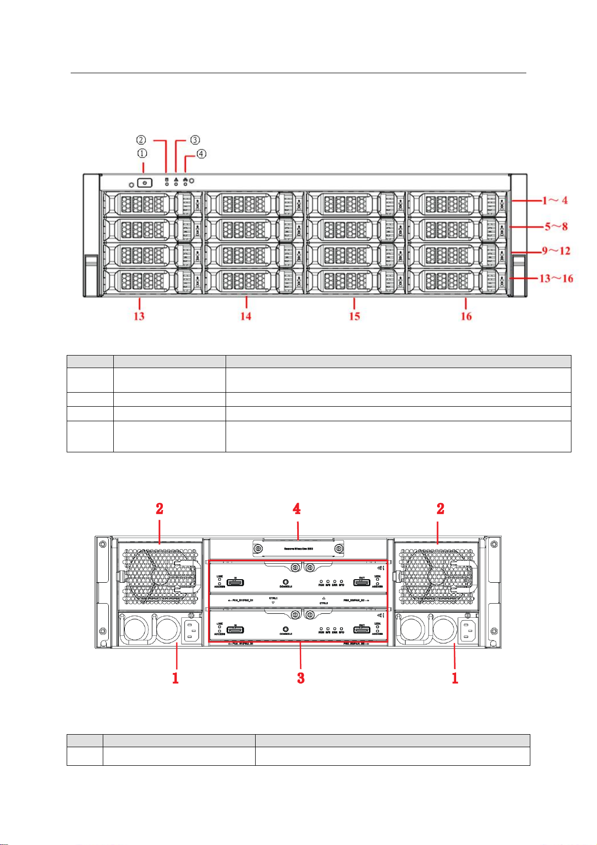
ESS Series User’s Manual
75
SN
Name
Function
①
Power on-off button
Press it to boot up the device.
Press it for 5 seconds to shut down the device.
②
HDD Indicator Light
When system HDD is reading or writing, the blue light becomes flash.
③
Alarm Indicator Light
The red light is flashing when there is an alarm or abnormal situation.
④
Network Indicator
Light
The light is reserved for future use.
SN
Port
Function
1
Power port
Connect to AC power supplying source.
5.4.1 Front Panel
The front panel is shown as below. See Figure 5-7.
The HDD slot number ranges from left to right, from top to the bottom.
Figure 5-7
5.4.2 Rear Panel
The ESS3116D-JR rear panel is shown as In Figure 5-8.
Figure 5-8
You can refer to the following sheet for detailed information of the rear panel.
Page 85
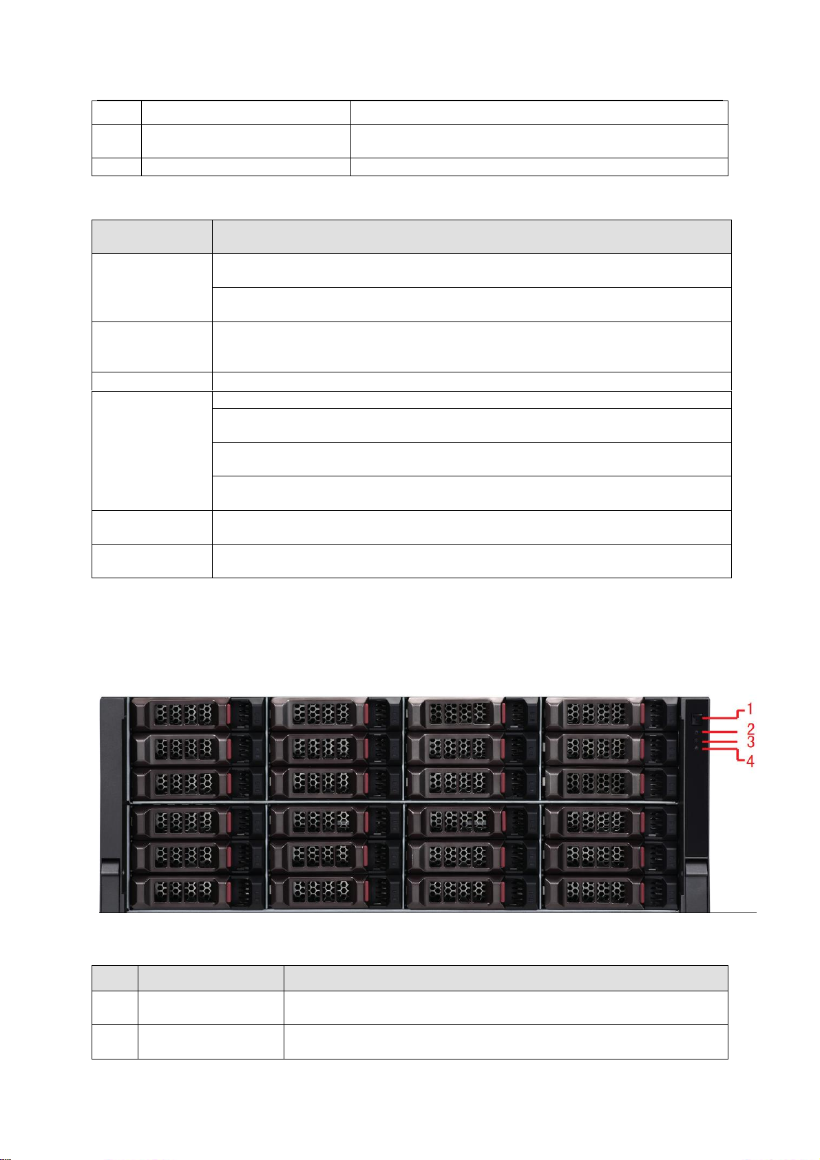
ESS Series User’s Manual
76
2
Fan
It is for case ventilation.
3
Main control module
It is about all kinds of ports and indictor light
introduction. Please refer to the following sheet.
4
Battery box
This slot is reserved for future use.
Port/Indicator
Light
Function
IN port indicator
light
The Link light is on when the IN port has connected to the host or the upperlevel disk array enclosure.
The Access light is on when the host is accessing the HDD of the disk array
enclosure.
IN port
Connect IN port to the host (such as ESS5016D) or the OUT port of the upperlevel disk array enclosure. Access the HDD of the disk array enclosure via the
IN port.
COM
Access system via COM. It is mainly for device debug.
Indicator light
The RUN light is on when device has booted up and is working.
M/S is main control indicator light. The light is on when system is working
properly. The light is off when the system is abnormal.
The ERR light is on when system is malfunction. The ERR light is off when
system is working properly.
The SPD light is on when the HDD access speed is abnormal. The SPD light
is off when HDD access speed is normal.
OUT port
Connect OUT port to the sub-level disk array enclosure to realize cascade
connection.
OUT port
indicator light
The Link light is on when OUT port has connected a sub-level device.
SN
Name
Function
1
Power on-off button
Press it to boot up the device.
Press it for 5 seconds to shut down the device.
2
HDD indicator light
When system HDD is reading or writing, the blue light becomes
flash.
You can refer to the following sheet for detailed information of main control module.
5.5 ESS3124S-J/ ESS3124S-JR
5.5.1 Front Panel
The front panel is shown as below. See Figure 5-9.
Figure 5-9
Page 86
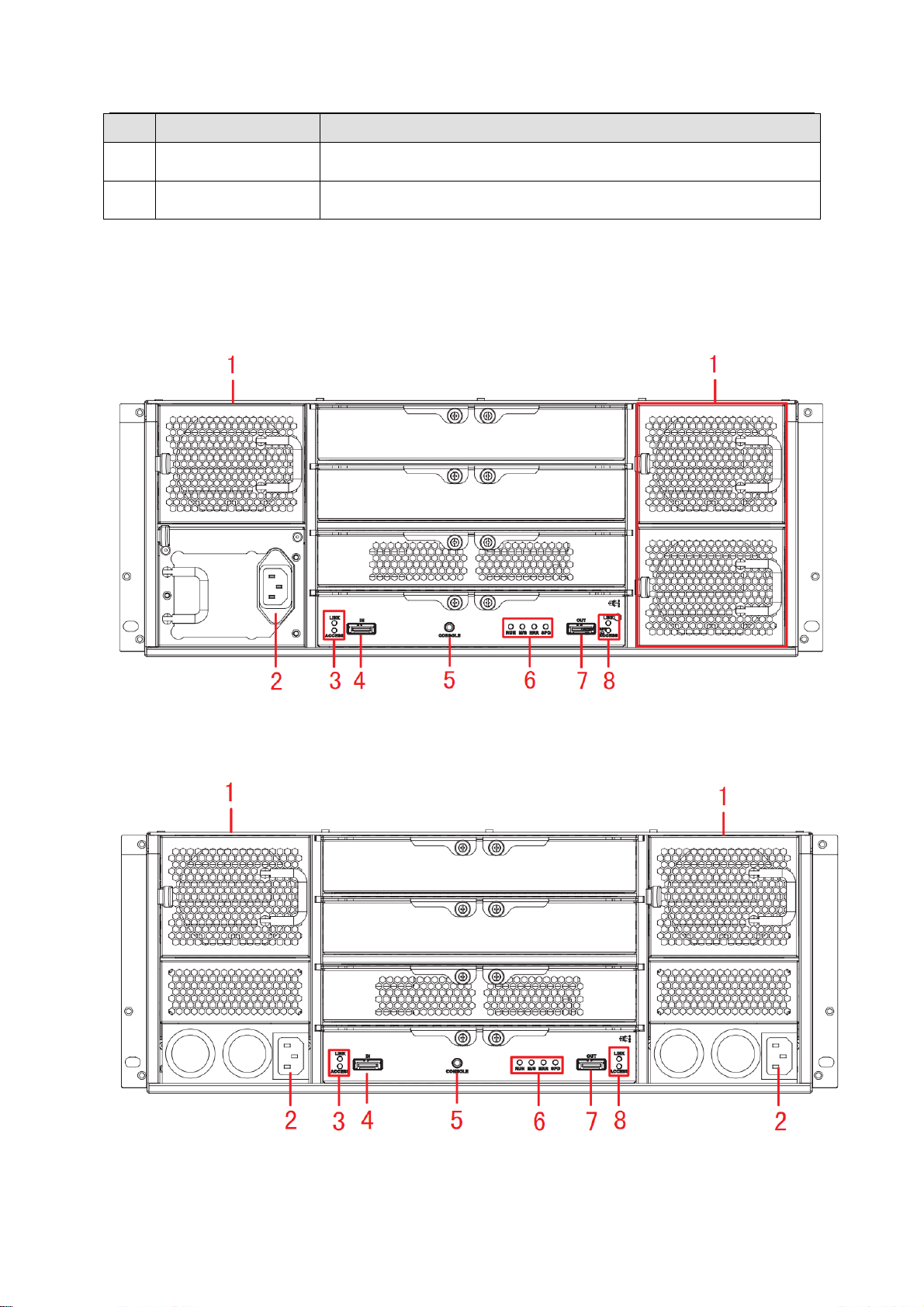
ESS Series User’s Manual
77
SN
Name
Function
3
Alarm indicator light
The red light is flashing when there is an alarm or abnormal
situation.
4
Network indicator
light
Reserved
5.5.2 Rear Panel
The rear panel has two types: single power and redundancy power. These two types have slight
difference on the power module and fan module. Please check carefully.
The single power mode rear panel is shown as below. See Figure 5-10.
Figure 5-10
The redundancy power series rear panel is shown as in Figure 5-11.
Figure 5-11
Page 87
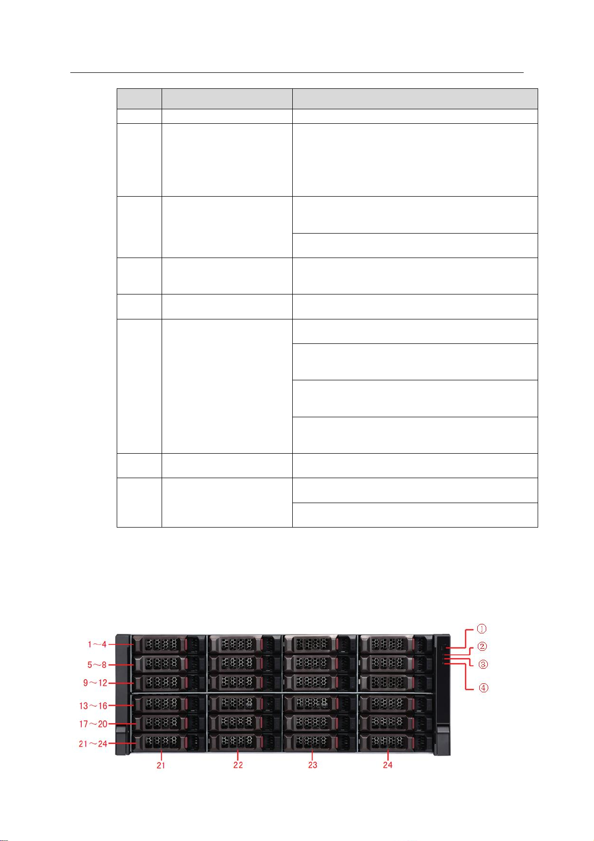
ESS Series User’s Manual
78
SN
Port
Description
1
Fan
For ventilation
2
Power port
Connect to AC power.
System beeps when you remove the
redundancy power.
System beeps when the power voltage or
temperature of the main board or the rear
panel is too high or too low.
3
IN port indicator light
The Link light is on when the IN port has
connected to the host or the upper-level disk array
enclosure.
The Access light is on when the host is accessing
the HDD of the disk array enclosure.
4
IN port
Connect IN port to the host or the OUT port of the
upper-level disk array enclosure. Access the HDD
of the disk array enclosure via the IN port.
5
COM
Access system via COM. It is mainly for device
debug.
6
Indicator light
The RUN light is on when device has booted up
and work properly.
M/S is main control indicator light. The light is on
when system is working properly. The light is off
when the system is abnormal.
The ERR light is on when system is malfunction.
The ERR light is off when system is working
properly.
The SPD light is on when the HDD access speed
is abnormal. The SPD light is off when HDD
access speed is normal.
7
OUT port
Connect OUT port to the sub-level disk array
enclosure to realize cascade connection.
8
OUT indicator light
The Link light is on when OUT port has connected
a sub-level device.
The Access light is on when there is data
accessing on the OUT port.
Please refer to the following sheet for detailed information.
5.6 ESS3124D-JR
5.6.1 Front Panel
The front panel is shown as below. See Figure 5-12.
The HDD slot number ranges from left to right, from top to the bottom.
Page 88
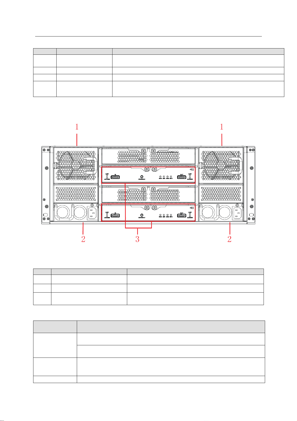
ESS Series User’s Manual
79
SN
Name
Function
①
Power on-off button
Press it to boot up the device.
Press it for 5 seconds to shut down the device.
②
HDD Indicator Light
When system HDD is reading or writing, the blue light becomes flash.
③
Alarm Indicator Light
The red light is flashing when there is an alarm or abnormal situation.
④
Network Indicator
Light
The blue light is flashing when the network connection is OK.
SN
Port
Function
1
Fan
It is for case ventilation.
2
Power port
Connect to AC power supplying source.
3
Main control module
It is about all kinds of ports and indictor light
introduction. Please refer to the following sheet.
Port/Indicator
Light
Function
IN port indicator
light
The Link light is on when the IN port has connected to the host or the upperlevel disk array enclosure.
The Access light is on when the host is accessing the HDD of the disk array
enclosure.
IN port
Connect IN port to the host (such as ESS5024D) or the OUT port of the upperlevel disk array enclosure. Access the HDD of the disk array enclosure via the
IN port.
COM
Access system via COM. It is mainly for device debug.
Figure 5-12
5.6.2 Rear Panel
The ESS3124D-JR rear panel is shown as In Figure 5-13.
Figure 5-13
You can refer to the following sheet for detailed information of the rear panel.
You can refer to the following sheet for detailed information of main control module.
Page 89
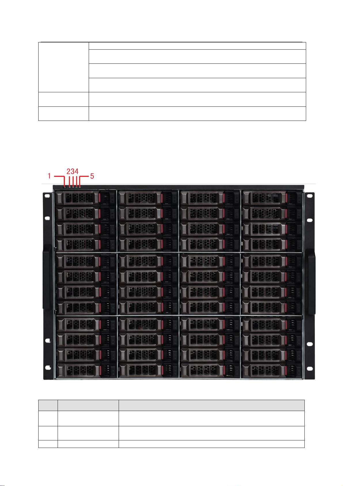
80
Indicator light
The RUN light is on when device has booted up and is working.
M/S is main control indicator light. The light is on when system is working
properly. The light is off when the system is abnormal.
The ERR light is on when system is malfunction. The ERR light is off when
system is working properly.
The SPD light is on when the HDD access speed is abnormal. The SPD light
is off when HDD access speed is normal.
OUT port
Connect OUT port to the sub-level disk array enclosure to realize cascade
connection.
OUT port
indicator light
The Link light is on when OUT port has connected a sub-level device.
SN
Name
Function
1
Power on-off button
Press it to boot up the device.
Press it for 5 seconds to shut down the device.
2
Power Indicator
Light
When the light is blue, the power connection is OK.
3
HDD indicator light
When system HDD is reading or writing, the blue light becomes
5.7 ESS3148S-J/ ESS3148S-JR
5.7.1 Front Panel
The front panel is shown as below. See Figure 5-14.
ESS Series User’s Manual
Figure 5-14
Page 90

ESS Series User’s Manual
81
SN
Name
Function
flash.
4
Alarm indicator light
The red light is flashing when there is an alarm or abnormal
situation.
5
Network indicator
light
Reserved
5.7.2 Rear Panel
The rear panel has two types: redundancy-power and 4-power. These two types have slight
difference on the power module and fan module. Please check carefully.
The redundancy-power mode rear panel is shown as below. See Figure 5-15.
The 4-power series rear panel is shown as in Figure 5-16.
Figure 5-15
Page 91

ESS Series User’s Manual
82
SN
Port
Function
1
Fan
It is for case ventilation.
2
Slave control module
It is about all kinds of ports and indictor light introduction.
Please refer to the following sheet.
3
Power port
Connect to AC power supplying source.
4
Main control module
It is about all kinds of ports and indictor light introduction.
Please refer to the following sheet.
Port/Indicator Light
Function
IN port indicator light
(Link/Access)
The Link light is on when the IN port has connected to
the host or the upper-level disk array enclosure.
The Access light is on when the host is accessing the
HDD of the disk array enclosure.
IN port
Connect IN port to the host or the OUT port of the upperlevel disk array enclosure. Access the HDD of the disk
array enclosure via the IN port.
CONSOLE
COM port. It is to debug the device and view the login
command interface.
Figure 5-16
Please refer to the following sheet for detailed information of the rear panel.
Please refer to the following sheet for detailed information of the main control module.
Page 92

ESS Series User’s Manual
83
Port/Indicator Light
Function
RUN
The light is on after system booted up and begins
running.
M/S
Master control indictor light.
The light is on when system is malfunction.
The light is off when system is running properly.
ERR
System error indictor light.
The error light is on when system is abnormal.
The error light is off when system is running
properly.
SPD
HDD speed indictor light.
The SPD light is on when the HDD accessing speed
is abnormal.
The SPD light is off when the HDD accessing speed
is normal.
OUT port
Connect OUT port to the sub-level disk array enclosure
to realize cascade connection.
OUT indicator light
(Link/Access)
The Link light is on when OUT port has connected a
sub-level device.
The Access light is on when there is data accessing on
the OUT port.
Port/Indicator
Light
Function
CONSOLE
COM port. It is to debug the device and view the login command
interface.
RUN
The light is flashing after system booted up and begins running.
M/S
Slave control indictor light.
The light is on when system is malfunction.
The light is off when system is running properly.
ERR
System error indictor light.
The error light is on when system is abnormal.
The error light is off when system is running properly.
SPD
HDD speed indictor light.
The SPD light is on when the HDD accessing speed is abnormal.
The SPD light is off when the HDD accessing speed is normal.
Enclosure
Host
ESS2016X-J
ESS3116S-J
ESS3124S-J
ESS3148S-J
ESS2016X
Cascade
No.
2 2 2
1
HDD No.
48
48
64
64
ESS5016S
Cascade
No.
4 4 4
2
HDD No.
80
80
112
112
Please refer to the following sheet for detailed information of the slave control module.
5.8 Disk Array Enclosure Cascade Connection
5.8.1 Cascade Connection Sheet
5.8.1.1 Single-Controller Series
For the single-controller series product, there is only one main control module and it can only
connect to the single-controller host.
Please refer to the following sheet for host model they can connect to and then recommend HDD
amount and max HDD amount.
Page 93

ESS Series User’s Manual
84
ESS5024S
Cascade
No.
4 4 4
2
HDD No.
88
88
120
120
ESS5048S
Cascade
No.
3 3 3
1
HDD No.
96
96
120
96
ESS5064S
Cascade
No.
2 2 2
1
HDD No.
96
96
112
112
EVS5000
Cascade
No.
2 2 2
1
HDD No.
48
48
64
64
EVS7024S
Cascade
No.
4 4 4
2
HDD No.
88
88
120
120
EVS7048S
Cascade
No.
3 3 3
1
HDD No.
96
96
120
96
Enclosure
Host
ESS3116D-J
ESS3124D-J
ESS5016D
Cascade
No.
4
4
HDD No.
80
112
ESS5024D
Cascade
No.
4
4
HDD No.
88
120
ESS5064D
Cascade
No.
2
2
HDD No.
96
112
EVS7024D
Cascade
No.
4
4
HDD No.
88
120
5.8.1.2 Dual-Controller Series
For the dual-controller series product, there are two main control modules and it can only
connect to the dual-controller host.
Please refer to the following sheet for host model they can connect to and then recommend HDD
amount and max HDD amount.
5.8.2 Cascade Connection Sample
5.8.2.1 Single-Controller Series
Important
Please use SAS cable to connect the main control module of the disk array enclosure to
the main control module of the host respectively. Otherwise, it may result in disk array
enclosure error if you misconnect or forgot to connect the SAS cable!
When connect ESS2016X to ESS2016X-J, the interface is shown as below. See Figure 5-17.
Page 94

ESS Series User’s Manual
85
Figure 5-17
When connect the ESS50XXS to the ESS31XXS-J, the interface is shown as below. See Figure
5-18.
Page 95

ESS Series User’s Manual
86
Figure 5-18
5.8.2.2 Dual-Controller Series
Important
Please use SAS cable to connect the main control module of the disk array enclosure to
the main control module of the host respectively. Otherwise, it may result in disk array
enclosure error if you misconnect or forgot to connect the SAS cable!
Here we are going to connect the ESS50XXD to the ESS31XXD-JR series product. See Figure
5-19.
If you want to connect to the EVS series product, please connect the IN port of the disk array
enclosure to the SAS port of the host.
Page 96
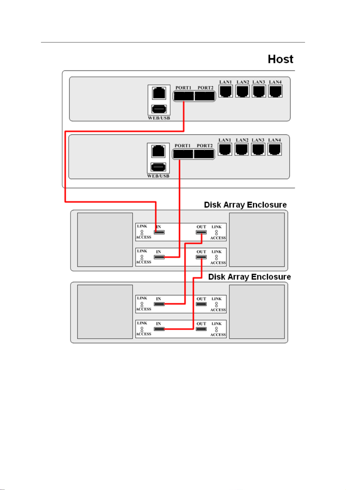
ESS Series User’s Manual
87
Figure 5-19
5.9 Boot up Disk Array Enclosure
Here we introduce the disk array enclosure and host connection.
Please make sure you have booted up disk array enclosure before you boot up the host.
a) Refer to Figure 5-1 to connect the power cable to the power port.
b) The power button of the rear panel is ON. (Please skip this step if there is no on-off
button at the rear panel).
Page 97
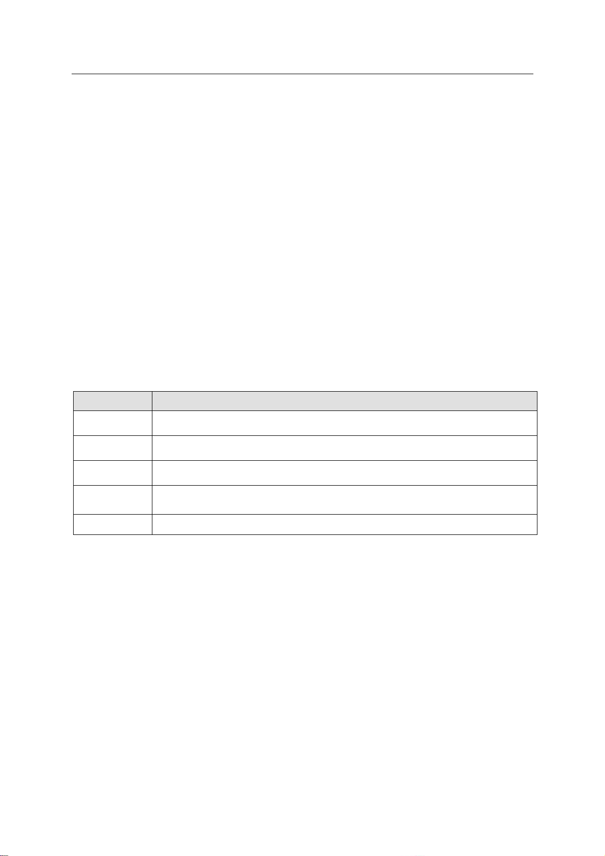
ESS Series User’s Manual
88
Parameter
Setup
Disk
information
On Disk information interface to view disk array enclosure disk information.
Please refer to chapter 3.4.1.
Add RAID
On Raid interface, select a RAID group on the disk array enclosure. Please
refer to chapter 3.4.3.
Add storage
pool
On Pool interface to create storage pool on the disk array enclosure. Please
refer to chapter 3.4.4.
iSCSI
On iSCSI interface to create iSCSI share on the storage pool of the disk array
enclosure.
Share
On share interface to select the storage pool from the disk array enclosure.
c) Press the power button on the front panel of disk array enclosure. The light is blue after
system boots up properly.
d) Please wait until the device boots up. The RUN light of the rear panel flashes when
system boots up successfully.
e) Boot up host after you have connected SAS cable.
5.10 Shut Down Disk Array Enclosure
a) Please make sure you have shut down host. See chapter 2.5.
b) Press power button to shut down disk array enclosure.
Important
Do not turn off disk array enclosure when the host is still running, or remove/insert the
SAS cable between these two devices. Otherwise, it may result in disk array enclosure
setup and data loss!
5.11 Disk Array Enclosure Setup
Please note disk operation and share applications of disk array enclosure are on WEB interface
of the host. Please refer to the following sheet for general setup information.
5.12 Update
5.12.1 Preparation
The disk array enclosure is mainly to expand the network storage capacity.
a) Before the update operation, please make sure you have backed up the important data
on the disk array enclosure.
b) Login the WEB interface of the host; stop share service and RAID synchronization
process on the disk array enclosure manually.
c) Save the update application such as General_ESSXXXXX-
Internel_V1.500.0001.6T.130824.bin.
5.12.2 Update Steps
All update steps of the disk array enclosure are on the WEB interface of the host. Please use a
SAS cable to connect the disk array enclosure to the host.
Page 98

ESS Series User’s Manual
89
a) Open the browser and input the IP address of the host. Click Enter button, you can see
system login interface. See Figure 5-20. Input administrator user name and password.
Default user name is admin and password is 888888888888.
Figure 5-20
b) From System->Upgrade interface, and then select disk array enclosure type from the
dropdown list. See Figure 5-21.
Figure 5-21
c) Click Browse button; select the applications you want to update. Please save the update
applications on the PC before the update begins.
d) You can see system pops up a dialogue box for you to confirm update operation.
Please click OK to continue. See Figure 5-22.
Page 99
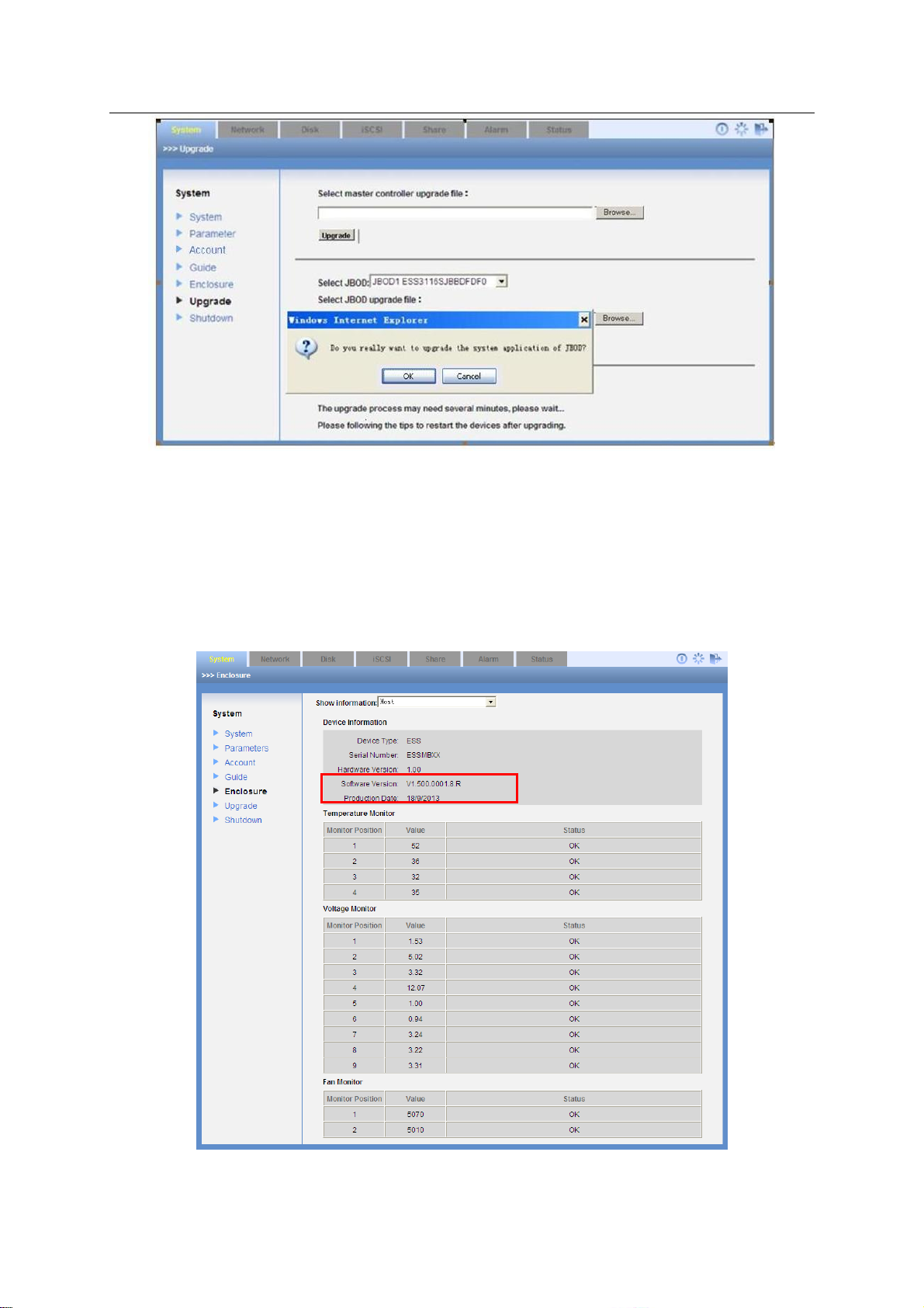
ESS Series User’s Manual
90
Figure 5-22
e) It may take about one minute to update. Please wait.
f) After the update process, please shut down the host according to the system dialogue
box and then reboot the disk array enclosure. Finally boot up host.
5.12.3 Check Update Result
After the update operation, from the system->Enclosure, you can select disk array enclosure
from the dropdown list. Now you can see current version number. See Figure 5-23.
Figure 5-23
Page 100

ESS Series User’s Manual
91
RAID
Level
Note
Min Disk
Needed
RAID0
RAID0 is so called Striped Disk Array without Fault Tolerance. It
represents the highest storage performance in RAID level. RAID0 is
to read-write continue data in several HDD. So, system data query will
be performed in several HDDs at the same time.
2
RAID1
It is also called Mirror or mirroring. Its aim is to maximally guarantee
data safety and restorable. RAID1 is to automatically copy user input
data fully to other RAID1 HDDs.
2
RAID3
RAID3 does not backup the storaged data. It saves the data
information on the member HDD of the RAID3 and save the
verification information on the verification HDD of the RAID3. The
verification information and the corresponding data are saved on
different HDDs. When one HDD of the RAID3 is damaged, it can use
the left data and then corresponding verification information to restore
the damaged data. At the same time, the RAID10 has the low storage
space usage rate (50%)as the RAID1.
RAID10
RAID10 assembles RAID0 and the RAID1. It uses the high read/write
speed of the RAID0 and the generally high data protection and
restores capability of the RAID1. These entire make RAID10 has
higher performance and security level.
RAID5
RAID5 does not backup the storage data. Instead, it will memorize
data and corresponding verification information to HDDs of RAID5.
The data and verification information will be backed up in different
HDDs respectively. When data in one of the HDDs is damaged,
system can use the rest data and corresponding verification
information to restore the lost data.
3
RAID6
Based on the RAID 5, the verification disk is two. The data and
verification information will be backed up in different HDDs
respectively. When data in two of the HDDs is damaged, system can
still use the rest data and corresponding verification information to
restore the lost data.
4
RAID50
RAID50 assembles the RAID5 and the RAID0. It uses multiple-group
RAID5 to form the RAID50 as the RAID0 mode. It can have the high
read/write speed of the RAID0 and it also has the data protection and
restores capability of the RAID5. Comparing with the RAID10,
RAID50 enhance the storage space usage rate. It max supports one
malfunction HDD on each sub-RAID5. It can use the data on other
HDDs to restore the data.
RAID60
RAID60 is based on RAID6,RAID0. Use multiple group of RAID6 to
6 Appendix A--- RAID Introduction
6.1 About RAID
RAID is an abbreviation for Redundant Array of Independent Disks.
It is to combine several independent HDDs (physical HDD) to form a HDD group (logic HDD) to
provide more storage capacity and data redundancy. Now it consists of seven levels, ranging
from RAID0 to RAID6.
6.2 RAID Level
 Loading...