

Page 1

ESS3016X- Internet Intelligent Storage User’s Manual
Page 2

ESS3016X User’s Manual
2
Table of Contents
1 FEATURES AND FUNCTIONS ..........................................................................7
1.1 Specifications .........................................................................................................................................7
1.1.1 ESS3016X Specifications................................................................................................................7
1.1.2 ESS3015A Specifications................................................................................................................7
1.2 Installation...............................................................................................................................................8
1.2.1 Preparation........................................................................................................................................8
1.2.2 Set Device..........................................................................................................................................8
1.2.3 HDD Installation................................................................................................................................8
1.2.4 Cable Layout......................................................................................................................................9
1.2.5 Boot up and Shut down..................................................................................................................10
2 SYSTEM OPERATION .....................................................................................13
2.1 Preparation Work.................................................................................................................................13
2.2 Network Setup......................................................................................................................................13
2.2.1 Set Controller IP Address..............................................................................................................13
2.2.2 Network Connection Test..............................................................................................................13
2.2.3 Set IP Address ................................................................................................................................14
2.3 Boot up Device.....................................................................................................................................14
3 ESS3016X WEB CONFIGURATION ................................................................16
3.1 Web Login.............................................................................................................................................16
3.2 System Management ..........................................................................................................................16
3.2.1 Display System Information...........................................................................................................16
3.2.2 Parameter Configuration................................................................................................................17
3.2.3 User Configuration.......................................................................................................................... 18
3.2.4 Guide................................................................................................................................................20
Page 3

ESS3016X User’s Manual
3
3.2.5 Upgrade............................................................................................................................................23
3.2.6 Shut down System..........................................................................................................................24
3.3 Network Management.........................................................................................................................24
3.3.1 Network Configuration....................................................................................................................24
3.3.2 Router Configuration......................................................................................................................27
3.4 Disk Management................................................................................................................................28
3.4.1 Display Disk Information................................................................................................................28
3.4.2 RAID Configuration.........................................................................................................................30
3.4.3 Storage Pool Configuration...........................................................................................................34
3.5 iSCSI Management .............................................................................................................................36
3.5.1 iSCSI Configuration........................................................................................................................36
3.6 Share Management.............................................................................................................................37
3.6.1 Share configuration ........................................................................................................................38
3.6.2 FTP Configuration...........................................................................................................................43
3.6.3 Service Management.....................................................................................................................43
3.7 Status Management ............................................................................................................................44
3.7.1 Log Review......................................................................................................................................44
3.7.2 Service Status.................................................................................................................................46
3.7.3 Resume............................................................................................................................................46
3.8 Reboot/Shut down...............................................................................................................................47
4 CREATE ESS3016X DEVICE NAS SHARE .....................................................48
4.1 Quickly Create NAS Share Process .................................................................................................48
4.2 NAS Share Example ...........................................................................................................................48
4.2.1 SAMBA Share Creation.................................................................................................................48
4.2.2 NFS Share Creation....................................................................................................................... 54
4.2.3 FTP Share Creation........................................................................................................................55
5 QUICKLY CREATE ESS3016X DEVICE ISCSI SHARE ..................................58
Page 4

ESS3016X User’s Manual
4
5.1 Quickly Create ISCSI Share Process...............................................................................................58
5.2 iSCSI Share Example .........................................................................................................................58
6 ESS3015A ........................................................................................................60
6.1 ESS3015A—ESS3016X.....................................................................................................................60
6.1.1 Disk Management...........................................................................................................................60
6.1.2 RAID Setup......................................................................................................................................61
6.2 iSCSI Management .............................................................................................................................63
6.2.1 iSCSI Setup.....................................................................................................................................63
6.2.2 Share Management........................................................................................................................64
7 APPENDIX A ---TERMS EXPLANATION .........................................................66
8 APPENDIX B--- DISK HOT SWAP OPERATION .............................................68
9 APPENDIX C ---SAMBA SHARE IMPLEMENTATION IN WINDOWS.............. 75
10 APPENDIX D---ISCSI APPLICATION IN MS WINDOWS.................................77
11 APPENDIX E—COM COMMAND.....................................................................83
Page 5

ESS3016X User’s Manual
5
Welcome
Thank you for using our internet intelligent storage system!
This operating manual is designed to be a reference tool for the installation and operation of your
system.
Before installation and operation please read the following safeguards and warnings carefully!
Page 6

ESS3016X User’s Manual
6
Important Safeguard and Warnings
1.Electrical Safety
All installation and operation should conform to your local electrical safety codes.
We assume no liability or responsibility for all the fires or electrical shock caused by improper
handling or installation
2.Installation
Keep upward. Handle with care.
Do not apply power to the unit before completing installation.
3.Qualified Engineers Needed
All installation here should be done by the qualified engineers.
All the examination and repair should be done by the qualified service engineers.
We are not liable for any problems caused by unauthorized modifications or attempted repair.
4.Environment
The server shall be installed in a cool, dry place away from direct sunlight, inflammable,
explosive substances and etc.
5. About Accessories
Be sure to use all the accessories recommended by manufacturer.
Contact you local retailer ASAP if something is missing or damaged in your package.
Page 7
ESS3016X User’s Manual
7
1 Features and Functions
The 3016X internet intelligent storage unit has installed all necessary software. It works in 1000M
network environment (recommended) or 10/100mbps Ethernet. You can use web browser (IE
6.0 recommended) to manage, set network parameter and create storage pool.
1.1 Specifications
1.1.1 ESS3016X Specifications
Specification ESS3016X
Network Port Dual 10/100/1000Mbps Ethernet
ports
Storage Media
16 SATA Ⅱ HDDs
HDD Installation Independent HDD bracket
Support HDD hot swap
Data Protection Support RAID0/ RAID1/ RAID5
Server Microsoft Windows
2000/XP/NT/Server2003
Linux/Unix
Fan Redundant dual ball bearing fan
MTBF>100 thousand hours
Redundant Configuration Support 2+1 hot swap power
Power Consumption
100V~240VAC;50Hz~60Hz;
Whole Unit Power Consumption
(16 SATA HDDs)
280W~350W
Dimension (H*W*D) 133*450*650(mm)
Working Temperature
5℃~40℃
Working Humidity
10%~80%(Non condensation)
Storage Environment
Temperature
-20℃~70℃
Storage Environment Humidity
5%~90%(Non condensation)
Extension Function
Max support 2 ESS3015A, total
46 HDDS
Altitude
-60m~3000m
Unit Weight (Exclude HDD) 33Kg
Certificate and Security China Compulsory Certificate
Unit Fan Support on-line update
1.1.2 ESS3015A Specifications
Specification ESS3015A
Dimension 440*133*650(mm)
Working temperature
5℃~40℃
Working humidity
10%~80%(Non condensation)
Storage environment temperature
-20℃~70℃
Storage environment humidity
5%~90%(Non condensation)
Altitude
-60m~3000m
AC input 100V~240V ±10% 60Hz/50Hz
Net power consumption About 76W
Whole unit power consumption
(15 SATA HDDs)
Below 240W
Page 8
ESS3016X User’s Manual
8
Power 300W
1+1 redundancy
Support on-line replacement
Quality 29Kg
Certificate China Compulsory Certificate
External interface RS232 serial port.
Three network interfaces
Normal Open/Normal Close relay
output
Network N/A
Fan Support on-line upgrade
HDD Support Max 15 HDDs
Support hot swap.
1.2 Installation
1.2.1 Preparation
Before installation please prepare the following items:
z SATA HDD
z Tools for HDD installation
z Network cable
1.2.2 Set Device
If you want to configure setup, please follow the steps listed below.
z HDD installation. Please refer to chapter 1.2.3
z Connect power cable and network cable. Please refer to chapter 1.2.4.
z Boot up device and check self-diagnosis is OK or not. Please refer to chapter 1.2.5.
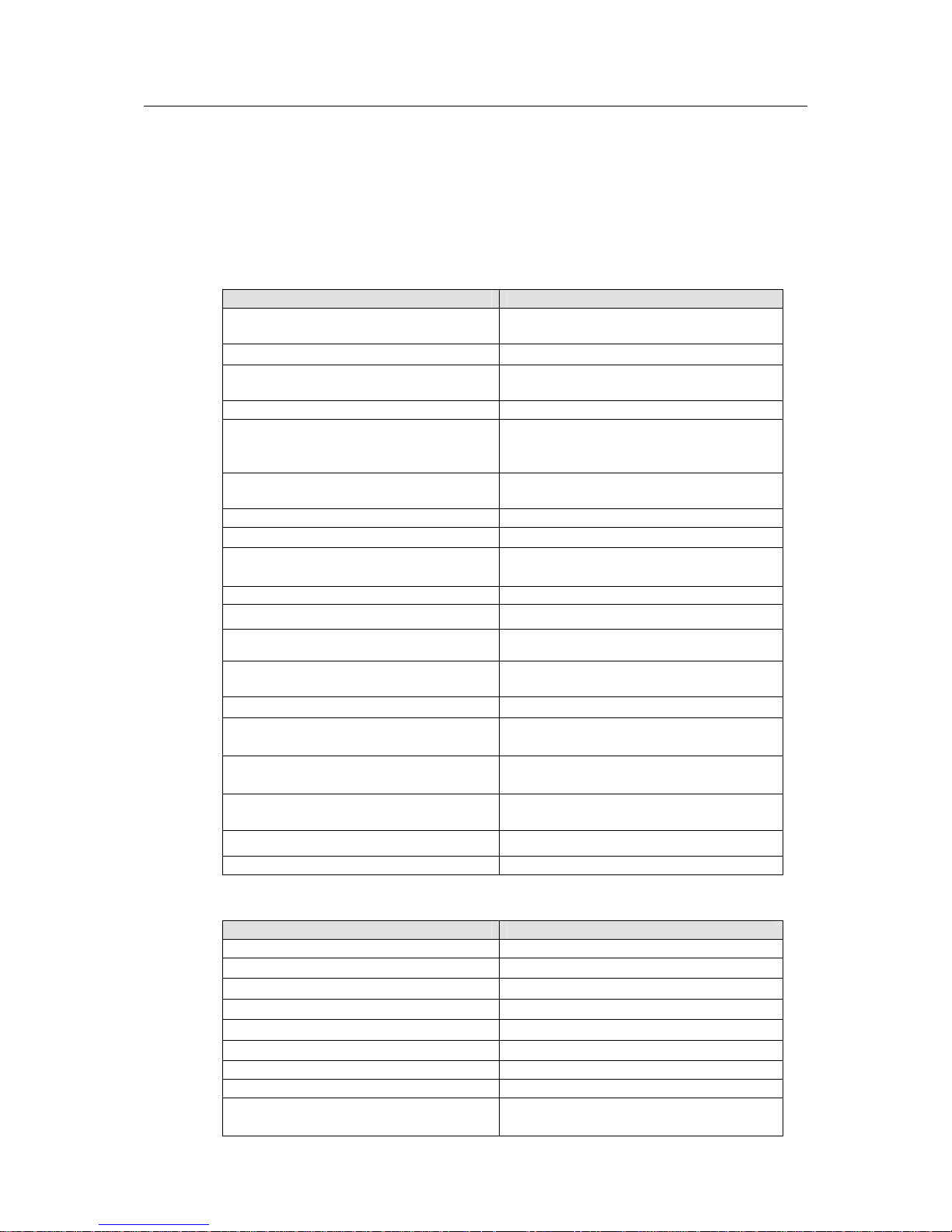
1.2.3 HDD Installation
You can use the HDD bracket in the chassis to install HDD.
First, pull out HDD bracket from the front panel.
Second, remove the bar that fixes the HDD bracket.
Third, use four screws to fix one HDD in the HDD bracket firmly.
The unit is shown as in Figure 1-1.
In the following figure, you can view HDD serial number. The value ranges from left to the right.
You can see the 13th to 16th at the bottom of the unit.
Page 9
ESS3016X User’s Manual
9
Figure 1-1
1.2.4 Cable Layout
1.2.4.1 ESS3016X
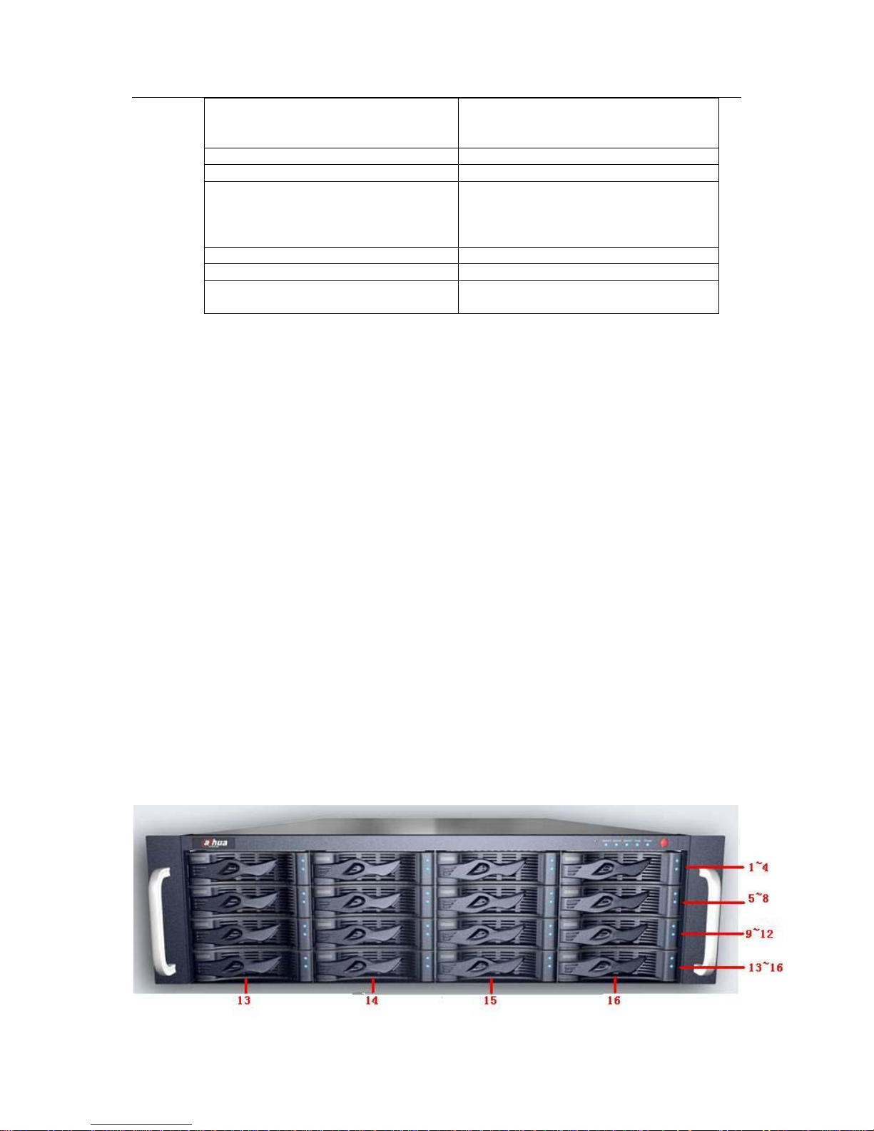
In Figure 1-2, you can see ESS3016X rear panel.
Figure 1-2
You can refer to the following sheet for detailed information.
SN Port Function
1 Power Port Connect to 220V AC
2 Mouse/keyboard port Connect to mouse or keyboard to view device status.
3 USB port Connect to USB device.
4 COM Connect to RS232 COM to go to the command
interface.
5 CRT Port Connect to displayer.
6 Ethernet port It is used to transmit data. 1000M Ethernet port.
7 Ethernet port It is used to transmit data. 1000M Ethernet port.
8 Extension Connection Port Connect to the extension disk rack.
1.2.4.2 ESS3015A
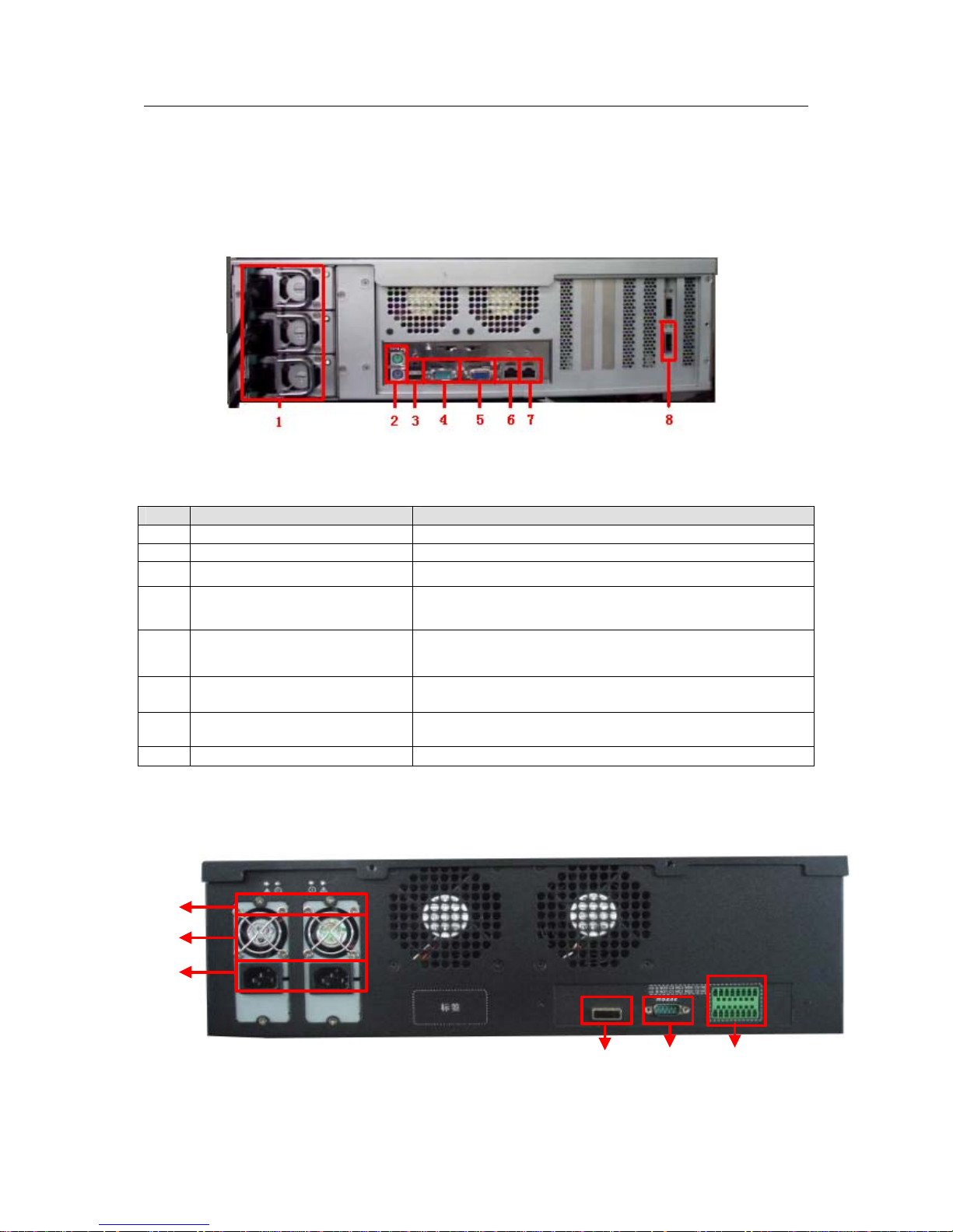
The ESS3015A rear panel is shown as below. See Figure 1-3.
1
2
3
456
Figure 1-3
Page 10
ESS3016X User’s Manual
10
You can refer to the following sheet for detailed information.
SN Port Function
1 Power indication light It is to display power working status. It becomes red
when alarm occurs. It becomes green when system is
working normally.
2 Power fan It is to help ventilation.
3 Power socket Connect to 100--240V AC.
4 Data channel connected to
the host
Connect it to the host.
5 COM Output alarm information.
NO1 C1 NC1 :HDD power channel alarm output
NO2 C2 NC2 :Fan alarm output
NO3 C3 NC3 :Redundancy power alarm output
NO4 C4 NC4: System alarm output(Including the above
three alarms)
6 Alarm relay output
NO: normal open
NC: normal close
C: public port
AB RS485 alarm output. G: ground end.
Note
Use special 1000M cable if your environment is 1000M.
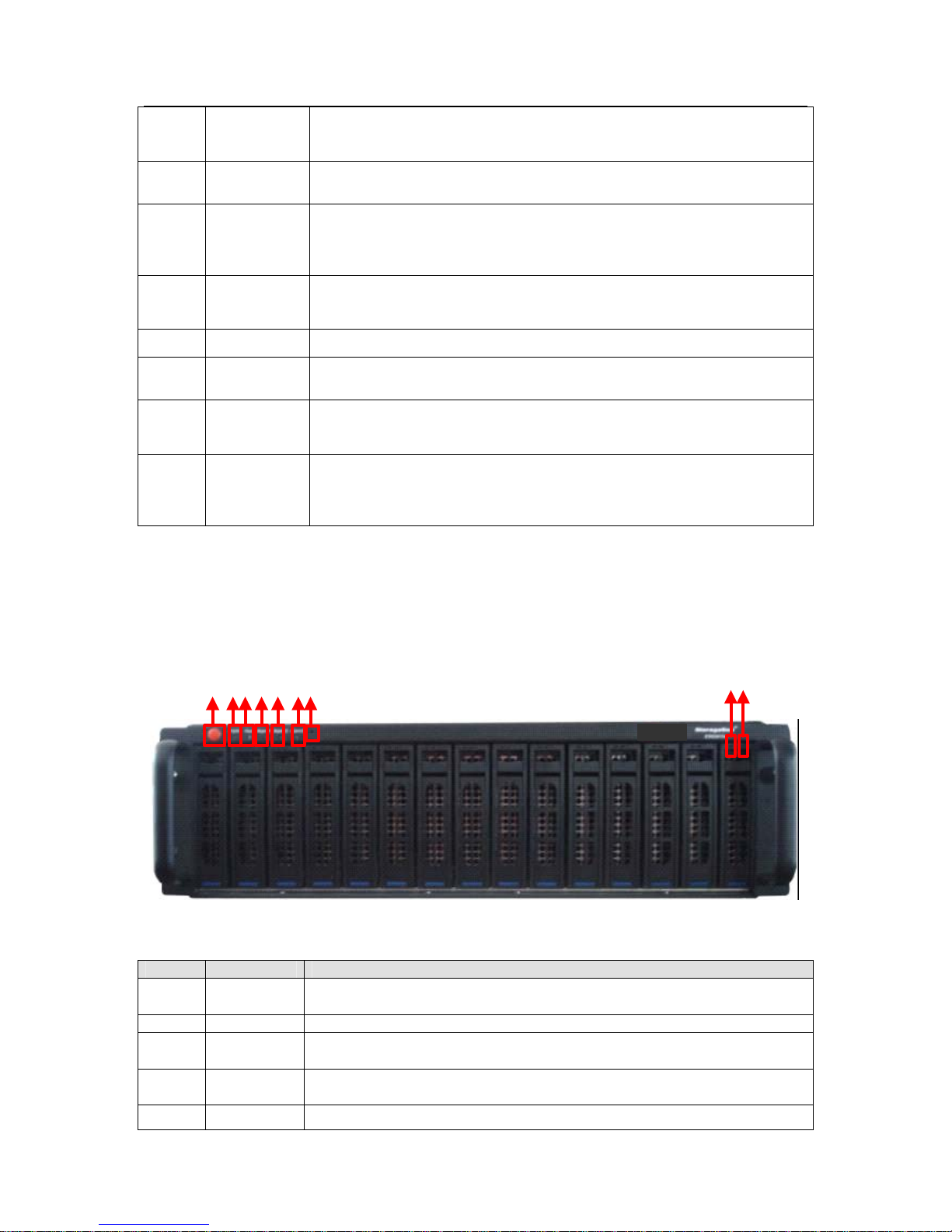
1.2.5 Boot up and Shut down
1.2.5.1 ESS3016X
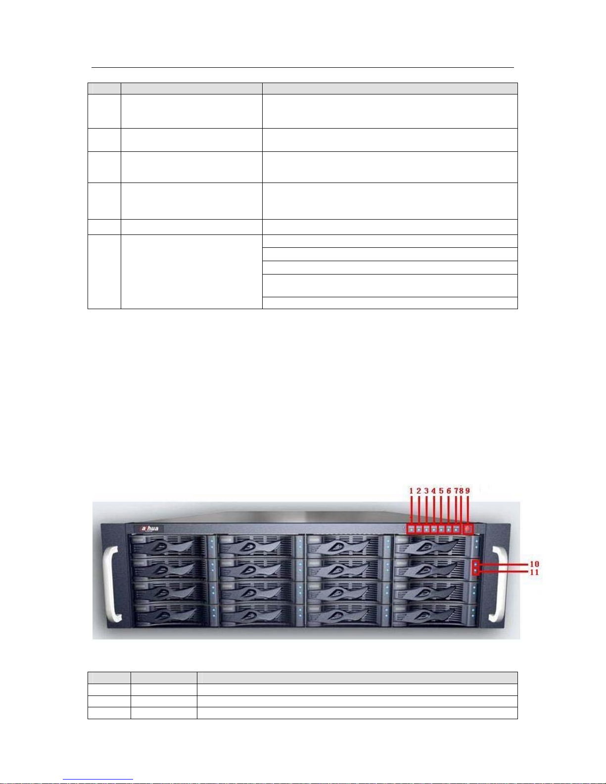
Please follow the steps listed below to boot up the device. See Figure 1-4.
z Connect the power cable to the system.
z Click the device power button to boot up the system. You can see power indication light
becomes yellow and all channel read-write indication lights flashed once. Now the boot up
completed.
If it is your first time to boot up system, you need to set network operation system
manually.
Figure 1-4
SN Name Function
1 Power Alarm If there is error in one of the three alarm sockets, the light becomes red.
2 Fan If there is alarm from the system fan, the light becomes red.
3 Temperature If there is alarm from the system temperature, the light becomes red.
Page 11
ESS3016X User’s Manual
11
4 NETb It is network data channel b indication light. The yellow light flashes if
the network port is working properly
5 NETa It is network data channel a indication light. The yellow light flashes if
the network port is working properly
6 System
HDD
Indication
Light
The blue light flashes when current channel is reading or writing data.
7 Power
Indication
Light
It becomes yellow after you connect device to the power.
8 RESET Click this button to reboot system.
9 System
Button
After connected the device to the power, click it to boot up the device.
10 HDD Power
Indication
Light
The yellow light flashes when connect the HDD channel to the power.
11 HDD Read-
write
Indication
Light
The blue light flashes when the system is reading or writing the HDD.
If you want to turn off unit power, please follow the following steps:
z In web interface, select option to shut down the system.
z Please wait until the blue HDD read-write light becomes off.
z Click PWR button to shut down the system.
1.2.5.2 ESS3015A
Please refer to Figure 1-5 for ESS3015A rear panel information.
12345
67
8
9
Figure 1-5
SN Name Function
1 On/off
button
After connecting to power, you can click this button to boot up the
system.
2 PWR LED Here is to display system has connected to power or not.
3 Host LED The connection to the host is proper or not. The light is orange if the
connection is normal.
4 Alarm1
LED
It becomes red when HDD power alarm occurs.
5 Alarm2 It becomes red when system fan alarm occurs.
Page 12

ESS3016X User’s Manual
12
LED
6 Alarm3
LED
It becomes red when system power alarm occurs.
7 RESET Click this button to reboot system.
8 Channel
read-write
LED
The light flashes when current channel is reading or writing data.
9 Channel
power LED
The light turns on when you connect current channel to power.
Here we just introduce the situation when you connect ESS3015A to ESS3016X.
Please follow the steps listed below to boot up the system.
z Connect the device to the power.
z Connect the data cable to the unit.
z Boot up the unit(skip this step if unit has boot up)
z Click unit power button to boot up ESS3015A.You can see HDD channel read-write light
becomes red and then begin scanning.
z Please wait until the scan completed.
If you want to turn off unit power, please follow the steps listed below:
z Shut down the unit first.
z Click the PWR button of the ESS3015A to shut down the device.
Warning!
Do not shut down the ESS3015A directly or unplug the data cable when host is running, it may
result in RAID setup and data loss! You need to reboot the host to restore RAID and data.
Page 13
ESS3016X User’s Manual
13
2 System Operation
2.1 Preparation Work
z 10/100Mbps or 1000Mbps Ethernet hub or switcher.
z Controller of the following configuration: Windows 2000/XP, IE 6.0 Ethernet connection.
z Check the real panel cable layout is O.K or not. (Power cable, network card and etc)
2.2 Network Setup
internet intelligent default network setup is shown as below:
z IP: 192.168.0.111
z Gateway: 192.168.0.1
z Subnet mask: 255.255.0.0
Admin password:888888888888
To configure 3016X internet intelligent storage device, you need to set controller IP first.
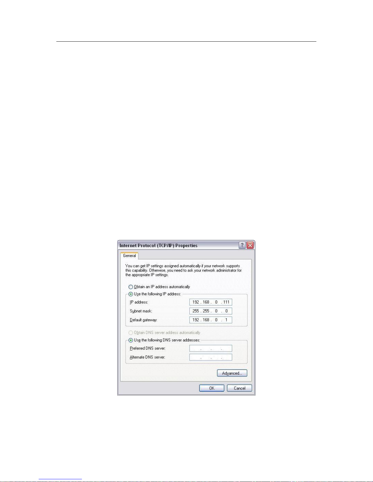
2.2.1 Set Controller IP Address
Right click My Network Places, select property. And then right click local connection and then
click property, double click internet protocol (TCP/IP).
In Internet protocol interface (see Figure 2-1), you can modify IP setup and then click O.K button.
Please note controller IP and device IP shall be in the same network section.
Figure 2-1
2.2.2 Network Connection Test
In DOS environment, input the command: ping 192.168.0.111. So as to check your network.
Page 14
ESS3016X User’s Manual
14
2.2.3 Set IP Address
Please follow the steps below to set device IP address.
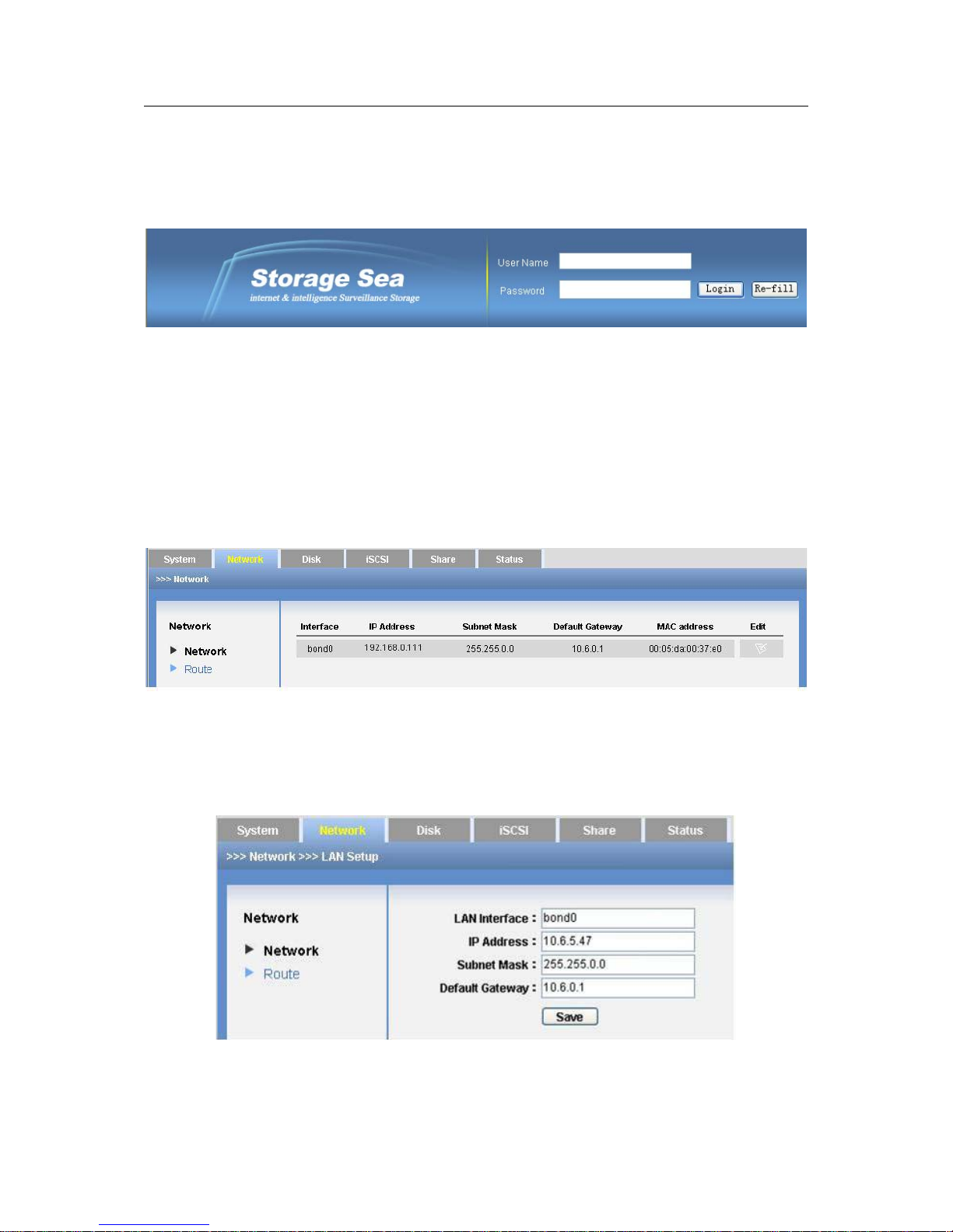
2.2.3.1 Input IP address
Open IE browser, input http://192.168.0.111(default IP address) you can see the login interface.
See Figure 2-2.
Figure 2-2
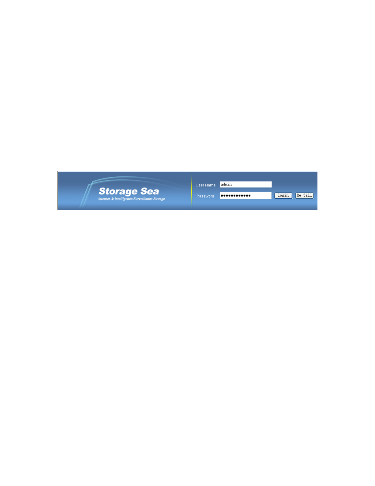
2.2.3.2 Log in
System user name is admin and password is 888888888888.
Admin is the system administrator account and has the highest priority.
For security reasons, please modify your password after first login (At least 12-digit).
2.2.3.3 Go to edit interface
In the main interface, from network to network and then click edit button. See Figure 2-3.
Figure 2-3
2.2.3.4 Input setup
The edit interface is shown as in Figure 2-4 .Here you can input your new IP address information.
Please input your IP address and gateway and then click save button.
Figure 2-4
2.3 Boot up Device
Page 15

ESS3016X User’s Manual
15
Open IE browser, and input http://10.6.5.47 in the address column (10.6.5.47 is a new IP
address you modified after you first logged in.). Input your user name and password, you can log
in. After you logged in, you can see an interface consisting of six parts.
z System
z Network
z Disk
z ISCSI
z Share
z Status
Page 16
ESS3016X User’s Manual
16
3 ESS3016X Web Configuration
ESS3016X internet intelligent storage software operation consists of seven parts.
z Web login
z System management
z Network management
z Disk management
z iSCSI management
z Share management
z Status management
3.1 Web Login
In windows OS, open IE browser and then input system IP address. Click Enter, you can see the
following interface. See Figure 3-1.
Figure 3-1
Our recommended controller configuration is: Windows 2000/XP, IE 6.0 or higher.
3.2 System Management
In this interface, you can see the following six parts.
z Display system information
z Parameter configuration
z User management
z Guide
z Upgrade
z Shut down
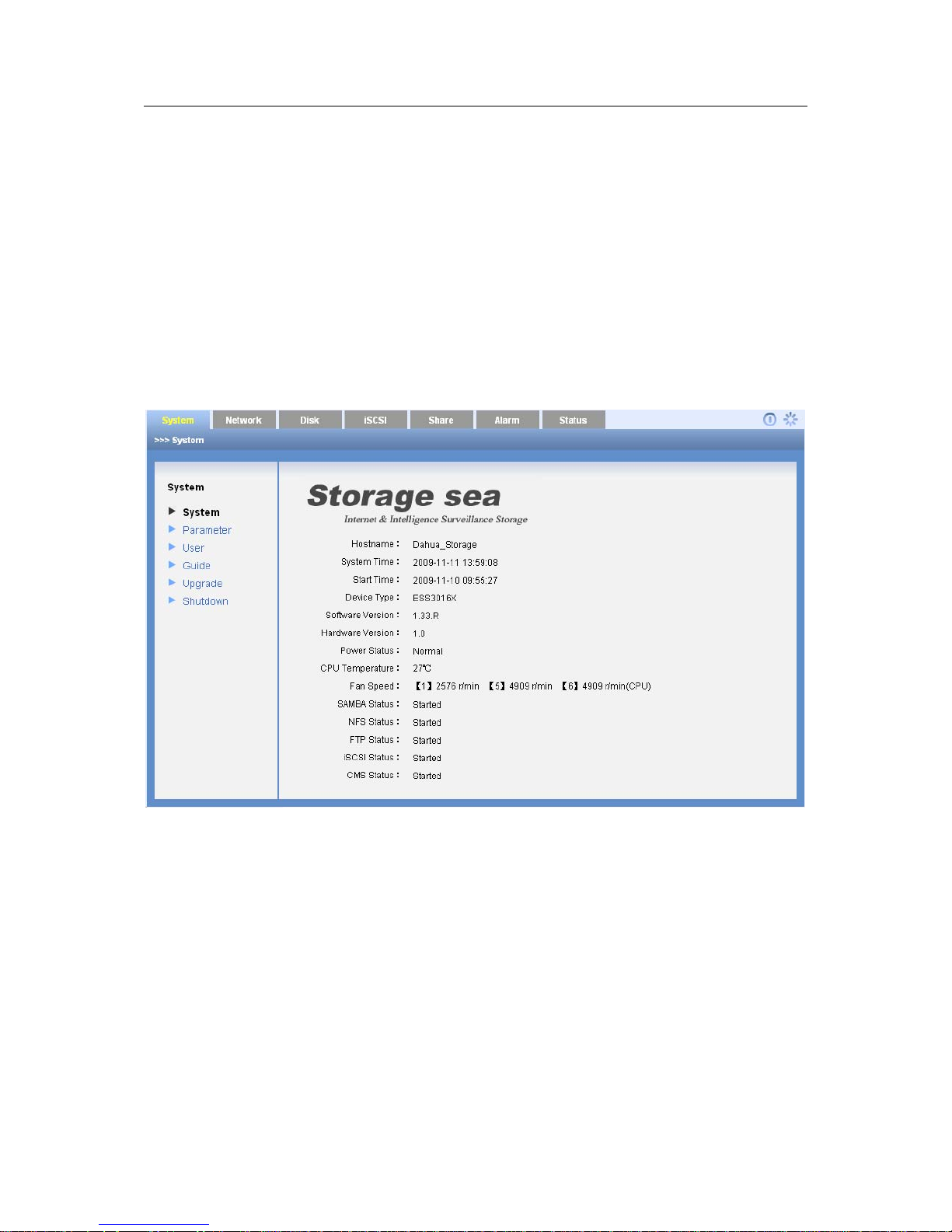
3.2.1 Display System Information
After you logged in, you can see system information interface. Or you can click system and then
select system information item to go to current interface. See Figure 3-2.
The red font means current item has not been enabled.
Here you can see the following information:
z Host name
z System time
z Start time
z Device type
z Software version
z Hardware version
z Power status
Page 17
ESS3016X User’s Manual
17
z CPU temperature
z Fan speed
ESS3016X display three fans speed. One is CPU fan speed.
z SAMBA status
z NFS status
z FTP status
z iSCSI status.
z CMS status
Note
If it is your first time to go to the system, please set system time.
When chassis is above threshold 55℃ or fan speed is below 1500r/m, system may display in red
font to remind you.
Figure 3-2
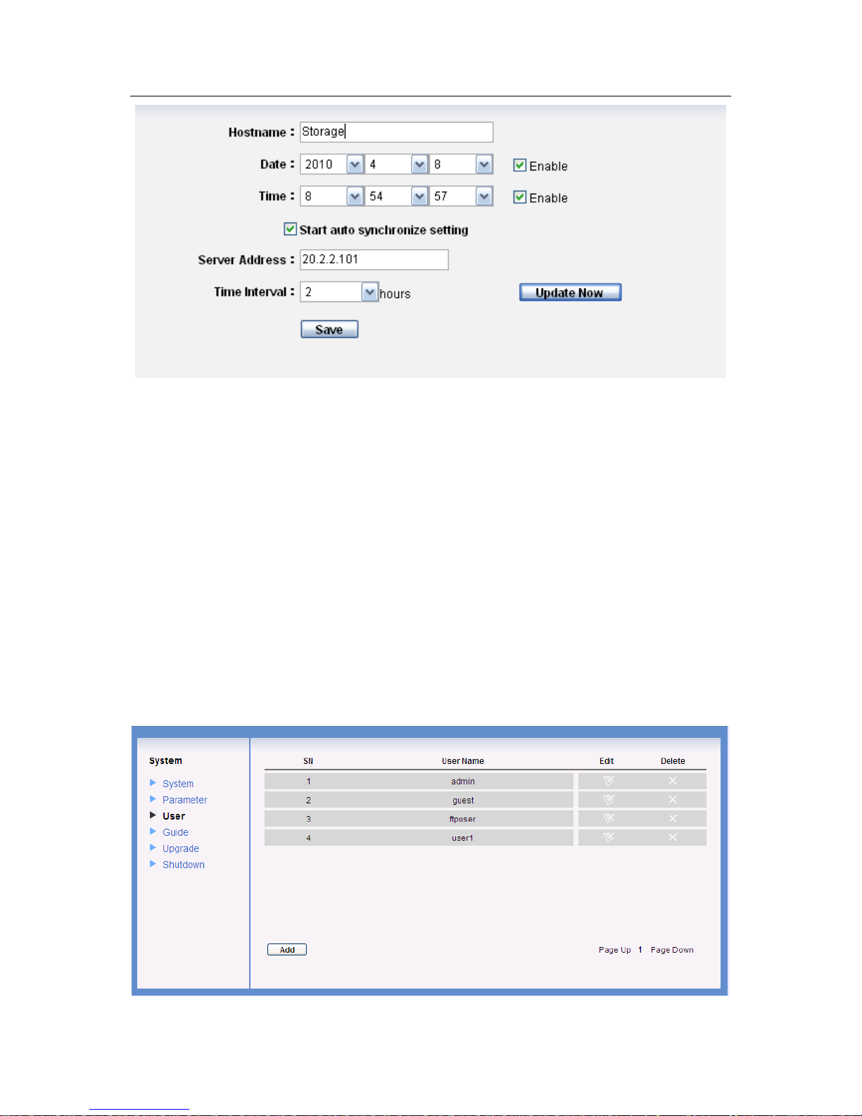
3.2.2 Parameter Configuration
Click parameter configuration button, you can see the following interface. See Figure 3-3.
z Host name
z Date
z Time
z Time Synchronize
Please note the server IP and the device IP shall be in the same section.
Click update now you can see the system synchronize time with the server. You can see the
proper dialogue box if there is an error.
Page 18
ESS3016X User’s Manual
18
Figure 3-3
3.2.3 User Configuration
Click user configuration button, you can see the following interface. See Figure 3-4.
For one user, there are two conditions:
z Administrator: it is the admin. This user can read, write or delete all storage data in current
system. It can configure the whole system and set ordinary user share folder rights.
z Ordinary user, it refers to all users except admin. Ordinary user (such as guest) can modify
its own password, review and save itself operation log, read and write in the corresponding
folder.
Please note, in ordinary user, “ftpuser” has two IDs. It is the ordinary system just like the guest
and it is also the default FTP service user.
Default password.
z admin: 888888888888
z guest: 666666666666
z ftpuser: 111111111111
Page 19
ESS3016X User’s Manual
19
Figure 3-4
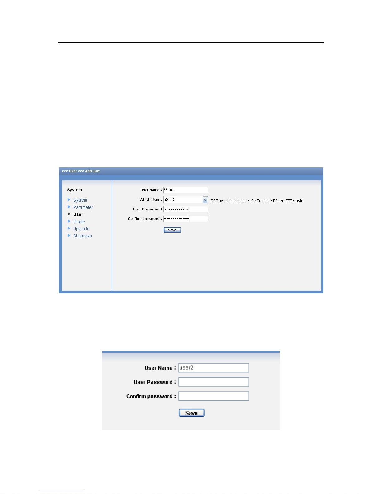
3.2.3.1 Add User
In Figure 3-4, click add button, you can see the following interface. See Figure 3-5.
After input new user information, please click save button. System goes back to user
management interface.
Please note there are two types of users: iSCSI user and SAMBA/NFS/FTP user. For iSCSI user,
the password length shall be more than 12-digit. For SAMBA/NFS/FTP user, there is no such a
kind of requirement. The iSCSI user can use the SAMBA/NFS/FTP service, and the
SAMBA/NFS/FTP user can use the iSCSI service only if its password is more than (or equal to)
12-digit.
Important
The user name consists of the character and number. The iSCSI user password shall be more
than 12-digit.
Figure 3-5
3.2.3.2 Edit User password
Click edit button of corresponding user, you can see the following interface. See Figure 3-6.
For the administrator, you do not need to input old password. You just input new password and
confirm, you can modify a user’s password.
Figure 3-6
Page 20
ESS3016X User’s Manual
20
3.2.3.3 Delete User
Select the delete button after the corresponding user, system pops up a dialogue box to remind
you that you are going to delete a user. Click O.K button, all the information of current user will
be deleted completely.
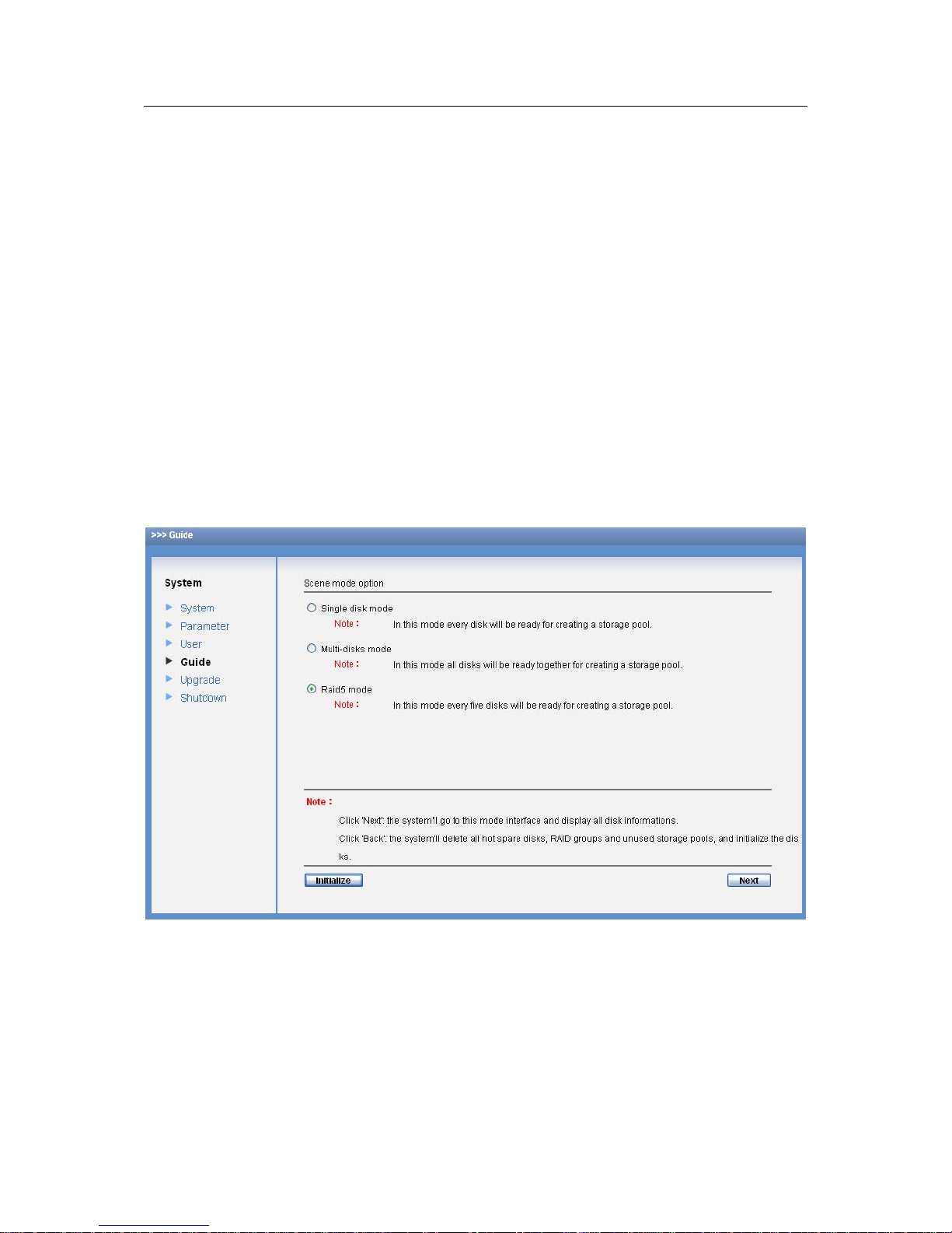
3.2.4 Guide
From system to guide, you can go to Guide interface. Guide function is to help you get familiar
with this device as soon as possible. You can follow the tip in each interface and then modify as
you need. You can just click next button to go on.
In the following procedures, we are going to create a SAMBA share in Raid5 mode.
z In web control interface, from system to guide, you can see an interface is shown as in
Figure 3-7.
Note
Please make sure there are 16 HDDs in current system and each HDD is free. Otherwise system
may pop up error prompt information.
Click the initialize button, system will automatically delete all storage pool and Raid5 device. If
there are some share folders in some storage pool, you need to delete them manually first.
Otherwise system may pop up error prompt information.
Figure 3-7
z In Figure 3-7 , enable Raid5 mode and then click next button. You can see an interface is
shown as in Figure 3-8.
Note
You can click back button to return to previous interface.
System can memorize administer operation. The next time when you log in as admin, from guide
to Raid5 mode, system automatically goes to next page. In that page, click next button. System
Page 21
ESS3016X User’s Manual
21
pops up a warning dialogue box to warn you .Please click Yes button to continue. Now you can
see an interface is shown as in Figure 3-8.
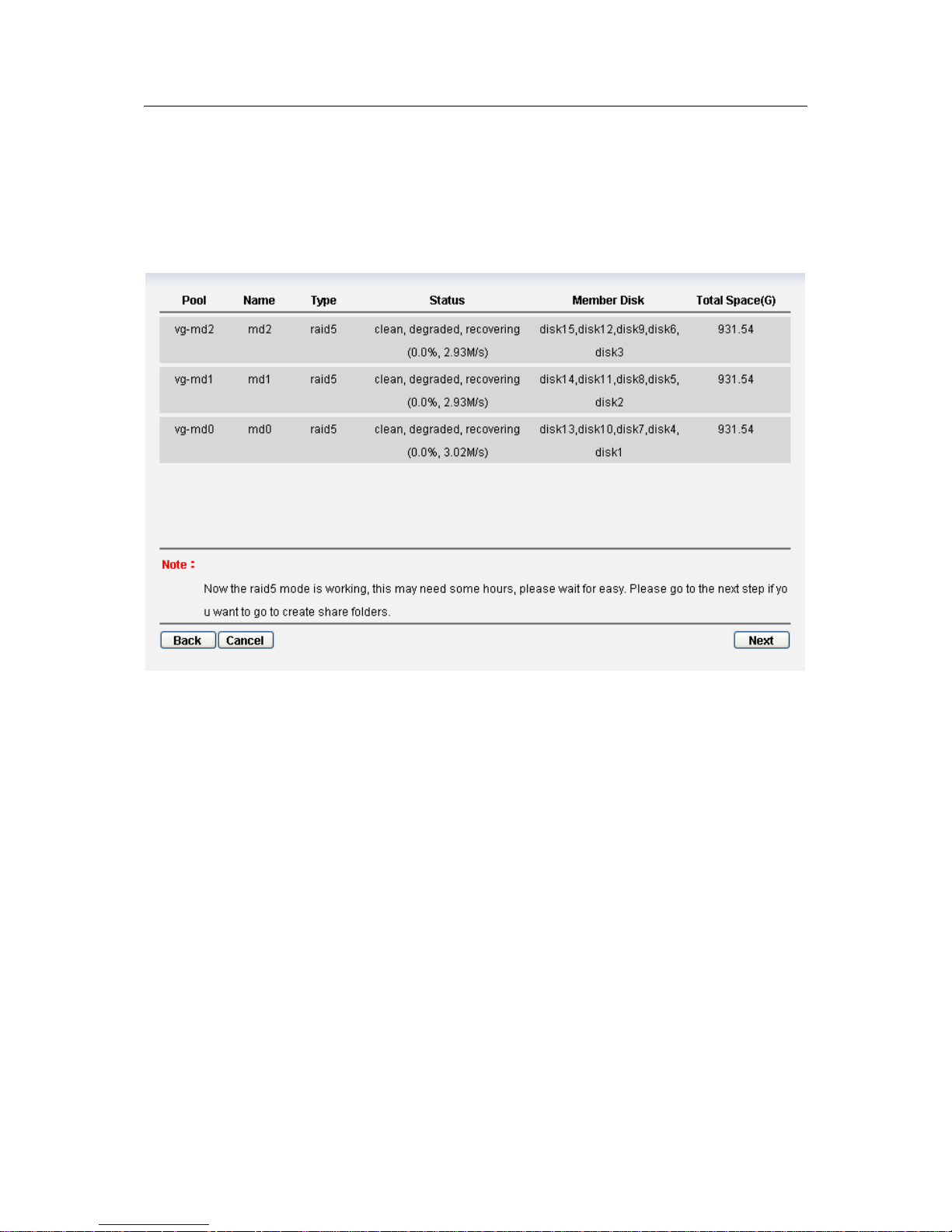
In Figure 3-8, you can see there are three Raid5 groups and each of them consists of five disks.
You can see there is storage pool in each group also.
You can click back button to return to previous interface. Click cancel button, system
automatically removes all storage pool and Raid5 device you just created and then goes back to
guide main interface (See Figure 3-7).
Figure 3-8
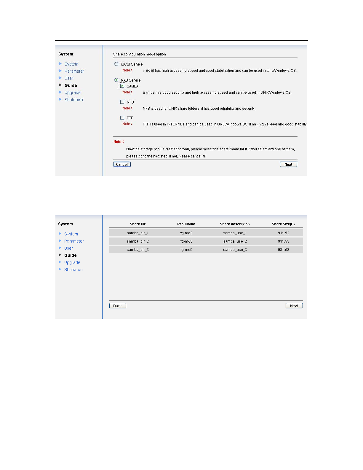
z In Figure 3-8, click next button. System pops up a warning dialogue box to warn you .Please
click Yes button to continue. Now you can see an interface is shown as in Figure 3-9 .Please
select NAS service and SAMBA item.
In this interface, you can enable iSCSI or NAS share. For NAS share, you can select more than
one item. Since we are going to create Raid5 mode, here we enable SAMBA service.
You can click back button to return to previous interface. Click cancel button, system
automatically removes all storage pool and Raid5 device you just created and then goes back to
guide main interface (See Figure 3-7).
Page 22
ESS3016X User’s Manual
22
Figure 3-9
z In Figure 3-9, click next button. System pops up a warning dialogue box to warn you .Please
click Yes button to continue. Now you can see an interface is shown as in Figure 3-10.
Figure 3-10
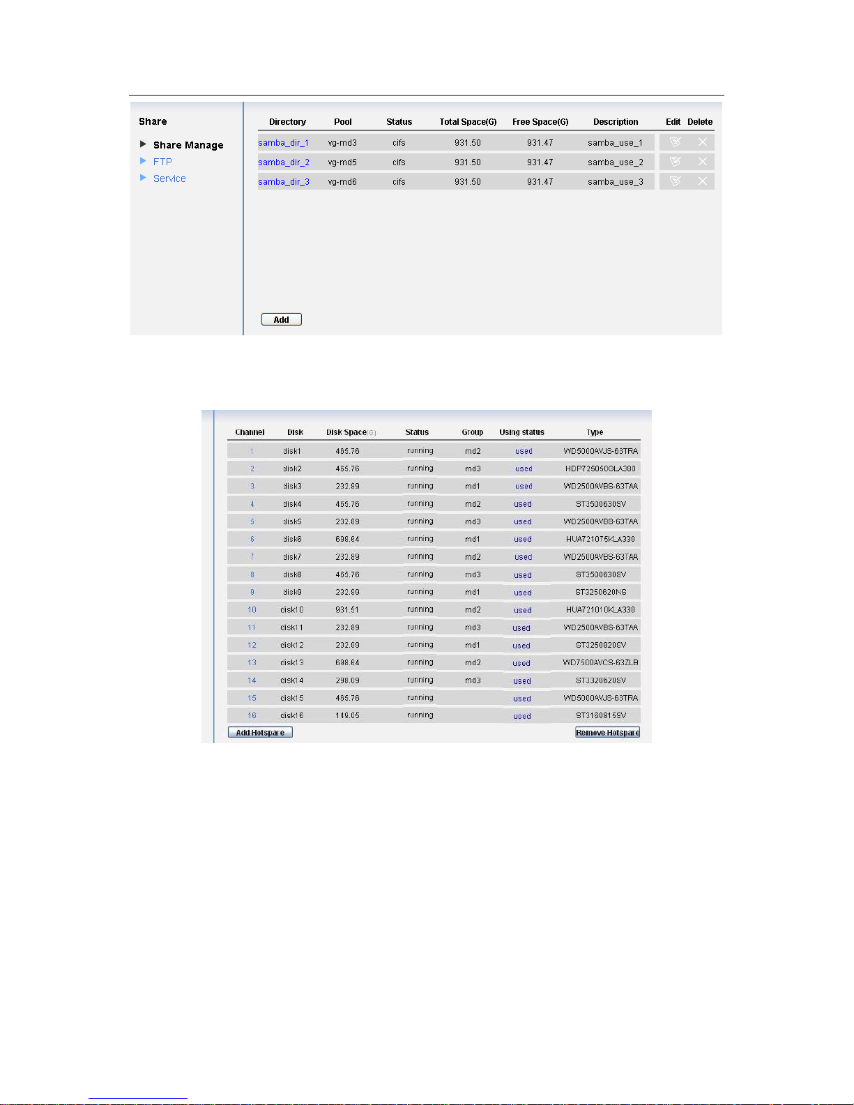
z In Figure3-10, click next button, you can see an interface is shown as in Figure 3-11.
Now, you can see there are three SAMBA share folders: samba_dir_1, samba_dir_2,
samba_dir_3.
Page 23
ESS3016X User’s Manual
23
Figure 3-11
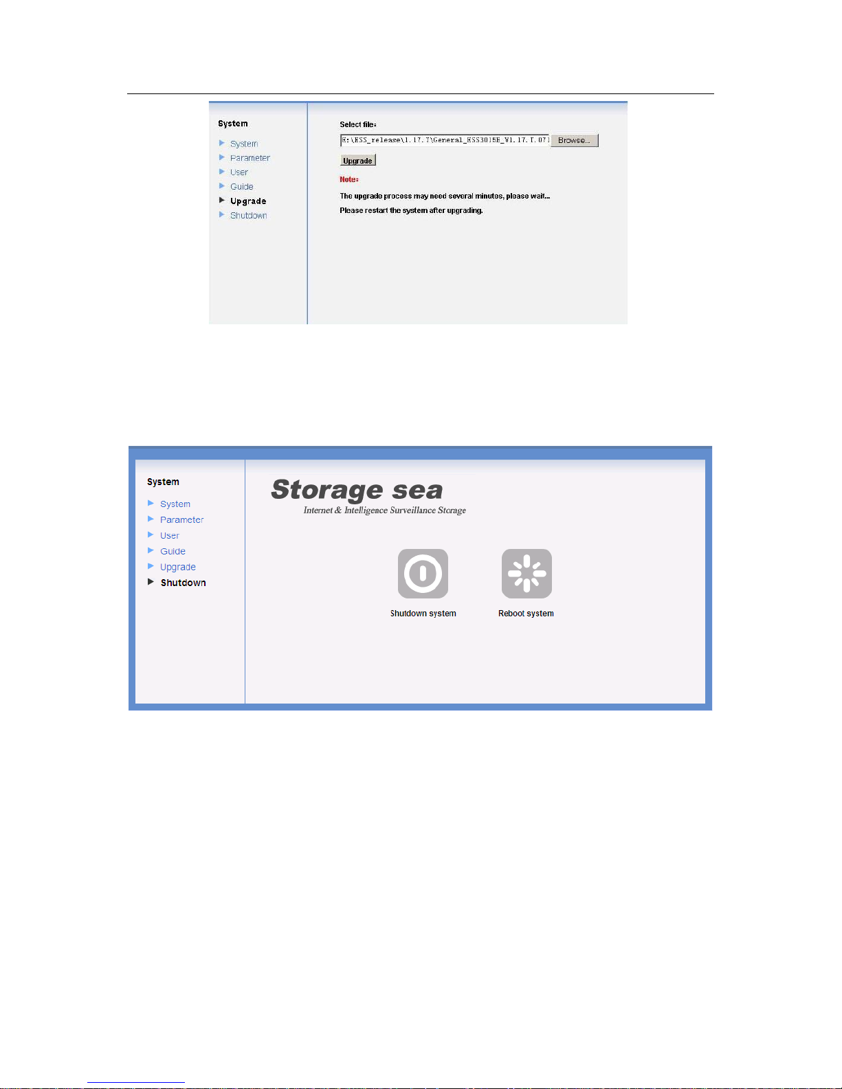
After the above operation, the page of disk manage is shown as below. See Figure 3-12.
Figure 3-12
3.2.5 Upgrade
From system to upgrade, here you can see a system upgrade interface is shown as in Figure
3-13.
Administrator can use this service to upgrade software.
After upgrading, please reboot your system.
In Figure 3-13, the upgrade file located at
E:\ESS_release\1.17.T\General_ESS3016X_V1.17.T.071113.BIN. Now you can click upgrade
button to begin update.
Note
Before you upgrade the system, please go to our official website to download the latest version.
Before you upgrade, please stop SAMBA, NFS, FTP, iSCSI service and RAID synchronization.
Page 24
ESS3016X User’s Manual
24
Figure 3-13
3.2.6 Shut down System
Click shut down system button; you can see the following interface. See Figure 3-14.
There are two options for you: shut down the system/reboot.
Figure 3-14
3.3 Network Management
In this interface you can set device network card and router in the LAN.
3.3.1 Network Configuration
Click network configuration button, you can see the following interface.
Here you can view current network card information. See Figure 3-15.
z Network card name
z IP address
z Subnet mask
z Default gateway
z Mac address
z Binding status
Page 25
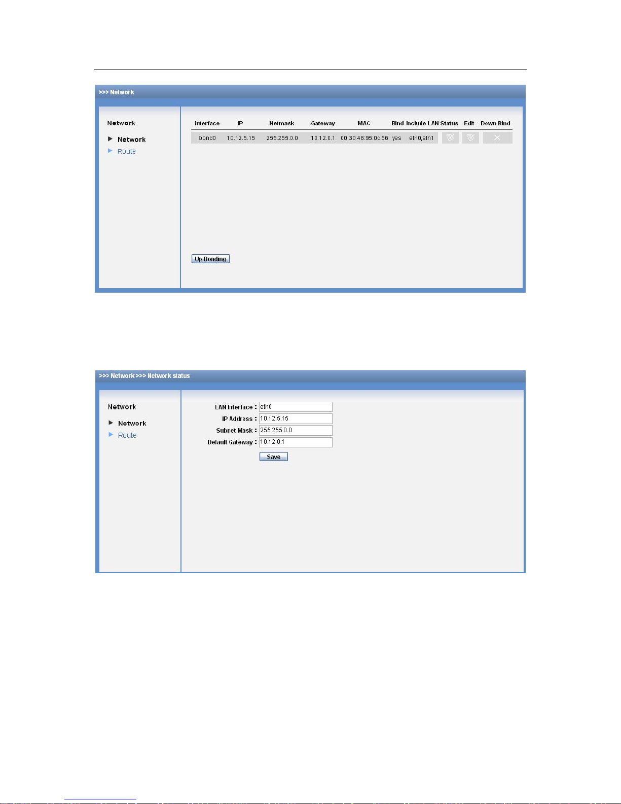
ESS3016X User’s Manual
25
z Member card
Figure 3-15
3.3.1.1 Set network card
In Figure 3-15, click edit button in, you can see the following interface. After your modification,
please click save button to exit. See Figure 3-16.
Figure 3-16
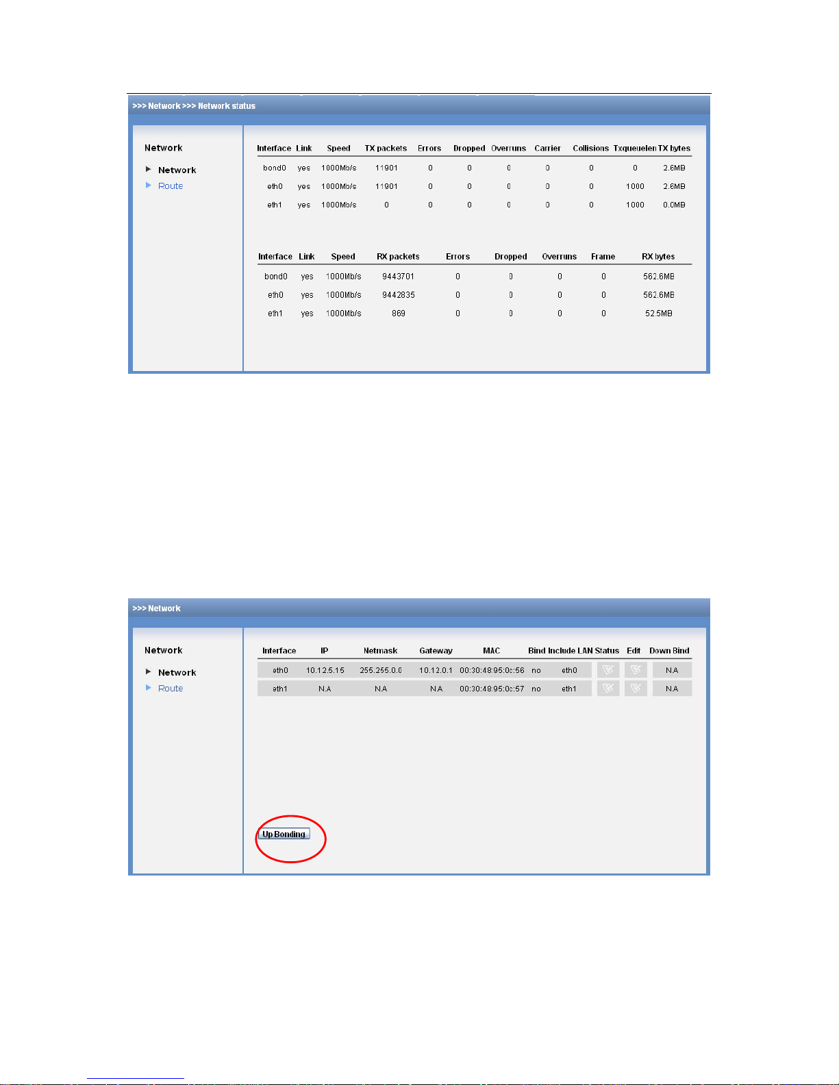
3.3.1.2 Status
Click the status button in Figure 3-15, you can view current network card physical connection
status and data send out and receive information. See Figure 3-17.
Page 26
ESS3016X User’s Manual
26
Figure 3-17
3.3.1.3 Remove binding
If you want to remove the network card binding, please click the remove binding button in Figure
3-15. Now you can see an interface is shown as in Figure 3-18.
These two cards are displayed respectively. The independent network card etho information is
the same as previous binding information.
If you want to view network card detailed information, please click status button. The interface is
similar to Figure 3-17.
If you want to configure the network card, please click corresponding edit button. The interface is
similar to Figure 3-16.
Figure 3-18
3.3.1.4 Binding the network card
Click the Up binding button in Figure 3-18, you can go to the following interface. See Figure 3-19.
Please select two network cards first and then input IP address, subnet mask and default
gateway. Click OK button you can complete the binding setup.
Page 27

ESS3016X User’s Manual
27
Figure 3-19
3.3.2 Router Configuration
From network, select router item, you can view current router setup. Click delete button,
administrator can delete a router. See Figure 3-20.
Figure 3-20
If network section has changed, you may need to modify router setup such as add one router.
After setting 1 and 2 routers as default network card, system default router setup and IP address
are varying when network IP address changes.
z Router 1: This default router setup can guarantee connection between intelligent device and
the PC of 10.6.0.0.
z Router 2. This default router setup can guarantee connection between intelligent device and
the PC out of 10.6.0.0.
Page 28
ESS3016X User’s Manual
28
3.4 Disk Management
Disk management is to display HDD physical information in the system, configure multiple HDDs
into RAID group and then create storage pool in the RAID group.
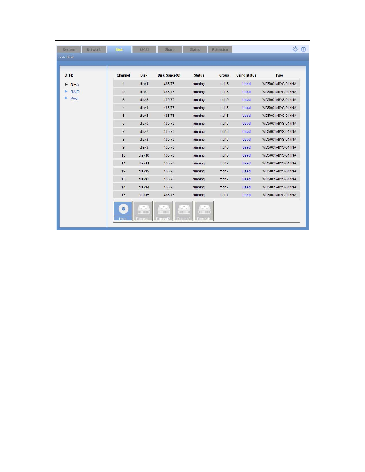
3.4.1 Display Disk Information
Click display disk information, you can see the following interface. See Figure 3-21.
Here you can review the following information.
z Serial number
z Channel number
z Disk Name
z Space
z Status
z Group name
z Using status
z Type
Figure 3-21
3.4.1.1 HDD S.M.A.R.T. information
When disk channel number is blue, it means current channel disk is available. Now you can view
disk S.M.A.R.T. information. Click one channel number; you can go to the following
S.M.A.R.T.information interface. See Figure 3-22.
It includes the following items:
z Channel
z Read error
z Boot up
z Reallocated
Page 29

ESS3016X User’s Manual
29
z Seek error
z Boot up
z Correct
z Temperature
z Rate
In the following interface, there are three buttons: return/detail information/initialization. See
Figure 3-22.
z Back: You can click it to go to previous interface.
z Initialization: it is to initialize the disk. Disk initialization is going to remove all data in current
disk. So, do not use it causally unless there is a must.
z Detail information: You can click it to view more detail information in a new interface. Click
return button you can go back to Figure 3-21.
Figure 3-22
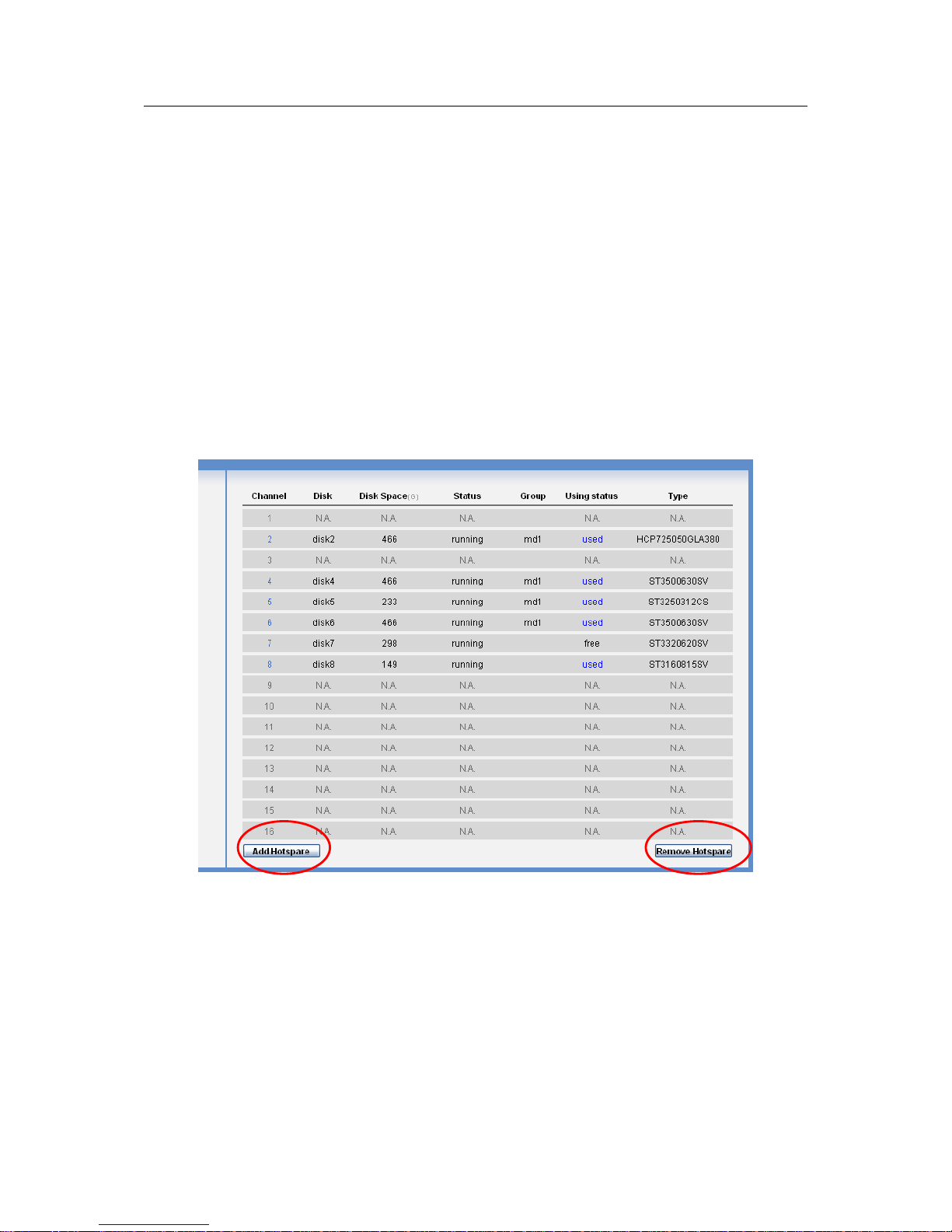
3.4.1.2 Add hot spare disk
In Figure 3-21, click add hot swap disk button, you can see an interface is shown as in Figure
3-23.
Here you can view idle disk list. You can click the select button to select the hot spare disk. Then
you can click save button to exit.
Please note one device can max have four hot spare disks.
Figure 3-23
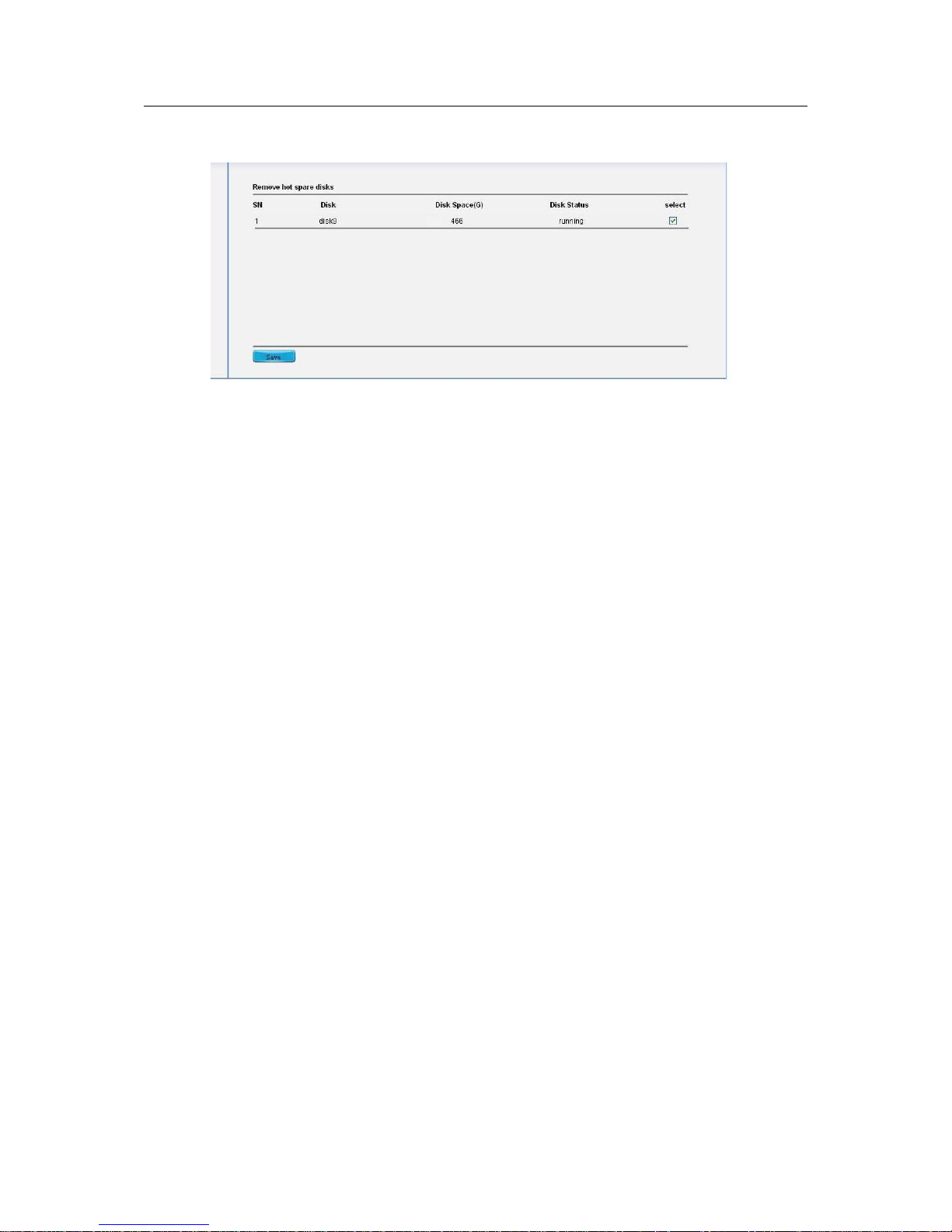
3.4.1.3 Remove hot spare disk
In Figure 3-21, click remove hot spare disk button, you can see an interface is shown as in
Figure 3-24.
Page 30
ESS3016X User’s Manual
30
Please note all the disks in the list are hot spare disks. You can click the select button and then
click save to remove the hot spare disk. The specified disk now becomes idle.
Figure 3-24
3.4.2 RAID Configuration
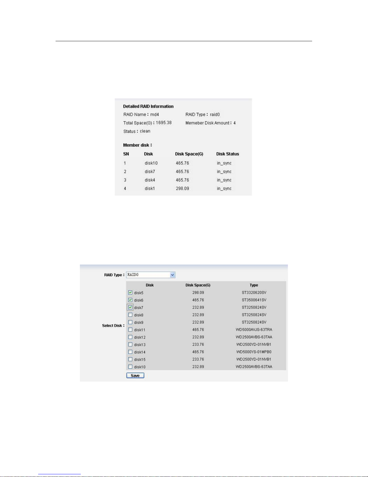
Click RAID button, you can see an interface is shown as in Figure 3-25.
Here you can see the following information:
z RAID name
z Type: RAID5 , RAID0 , RAID1
z Status: such as synchronization, or synchronization speed.
z Member disk
z Total space(Unit: G)
z The RAID consists of three statuses: “clean degraded,recovering”,“clean,resyncing” and
“clean”. You can refer to appendix A for status definition. If current RAID device is
malfunction, the status is “inactive”.
z RAID1 and RAID5 support data restore function, but it becomes usable after synchronization.
In Figure 3-25, you can get the following information:
z There are four RAID devices, device names are :md44,md45,md46,md47 and among
which, md47 is RAID0 device,md46 is RAID1 device and others are RAID5 device.
z Md47 has finished synchronization (Its status is shown as clean). Md46, md45 and md44
are synchronizing. Here you can also see synchronization speed and progress. For example,
for md44, it has completed 3.3% and synchronization speed is 3.02MB/s.
z Md47 member disks are disk12, disk13, disk14 and disk15.
Md46 member disk are disk9 and disk11.
Md45 member disk are disk5, disk6, disk7 and disk8.
Md44 member disk are disk1, disk2, disk3 and disk4.
z Md47 total space is 1462.50G
Md46 total space is 465.76G
Md45 total space is 698.66G
Md44 total space is 698.66G
Page 31

ESS3016X User’s Manual
31
Please refer to the following content for RAID device space calculation.
1) RAID 5:the total amount of N *disk =(N-1)× min(capacity) among which, capacity N stands
for the aggregation of the total disk. You can refer to the amount displayed on the web.
2) RAID 1: the total amount of N*disk= min (capacity), among which capacity N stands for the
aggregation of the total disk. You can refer to the amount displayed on the web.
3) RAID 0: the total amount of N*disk=disk space *disk amount. You can refer to the amount
displayed on the web.
Note
If RAID device is synchronizing now, you can see the synchronization process and speed (MB/s).
During the synchronization process, please do not use current device to create the storage
logical volume
Figure 3-25
3.4.2.1 Edit RAID configuration
Click edit button, you can see the following interface. Here you can remove or add a disk. See
Figure 3-26.
Note
Only RAID1 and RAID5 can support disk remove or add operation.
Page 32

ESS3016X User’s Manual
32
Figure 3-26
1) RAID 5.
Remove disk: You can max remove one disk. The data will not be damaged and the RAID 5
device runs properly. Errors may occur if you remove more than one disk.
Important
Do not remove disk casually especially when the RAID is synchronizing. If you find one of the
RAID has a problem and need to be removed, please remove it first and then open the chassis
cover to dismantle the disk.
Insert disk: this operation is also forbidden during the synchronization process. You need to
remove one disk if you want to insert a new one. RAID begins new synchronization after inserting
a new one. The data in the disk will not be lost.
2) RAID1
Remove disk: You can max remove one disk. The data will not be damaged and the RAID 1
device runs properly. Errors may occur if you remove more than one disk.
Important
Do not remove disk casually especially when the RAID is synchronizing. If you find one of the
RAID 1 has a problem and need to be removed, please remove it first and then open the cover to
dismantle the disk.
Page 33
ESS3016X User’s Manual
33
Insert disk: this operation is also forbidden during the synchronization process. You need to
remove one disk if you want to insert a new one. RAID begins new synchronization after inserting
a new one. The data in the disk will not be lost.
3) RAID0
You can not remove or add disk operation. See Figure 3-27.
Figure 3-27
3.4.2.2 Add RAID configuration
Click add button, you can see the following interface.
In Figure 3-28, administrator can select RAID type such as RAID0 and then select the member
disk. The damaged or used disks will not be listed in current interface. Please click save button to
finish the operation.
Figure 3-28
3.4.2.3 Remove RAID configuration
The remove operation consists of the following three situations. You can refer to Figure 3-25.
z If current RAID is free (there is no storage pool), you can just click remove button to remove
it directly.
Page 34
ESS3016X User’s Manual
34
z If current RAID has been used (there is a storage pool), but there is no share folder. Click
remove button, you can see system pop up a dialogue to warn you. You need to remove
storage pool and then remove the RAID group.
z If current RAID has been used (there is a storage pool) and there is share folder. Click
remove button, you can see system pop up a dialogue box to warn you. You need to delete
share folder and storage pool first, and then you can remove the RAID group.
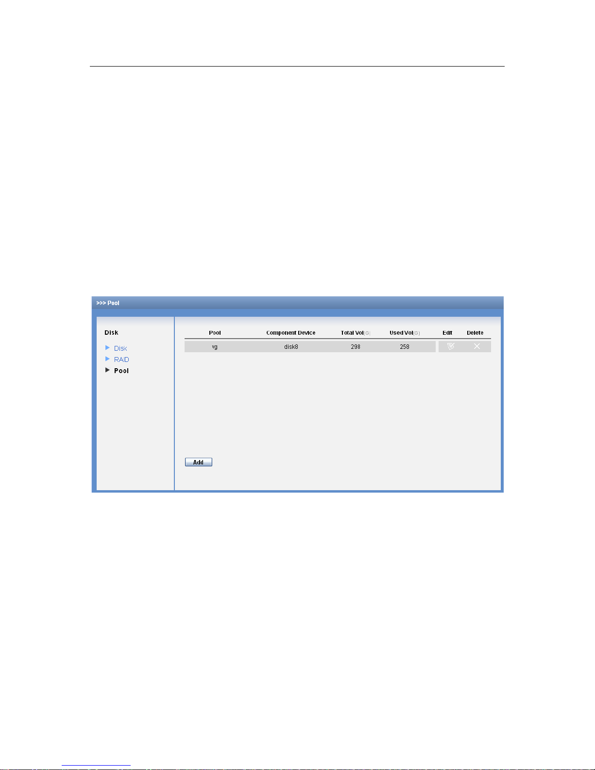
3.4.3 Storage Pool Configuration
In storage pool interface, you can see the following interface. See Figure 3-29.
Here you can view the following information:
z Storage pool name
z Member device.
z Total space
z Used space.
z Edit
z Delete
Figure 3-29
3.4.3.1 Add Storage Pool
In Figure 3-29, click add button, you can see the following interface. See Figure 3-30.
Here you can select RAID device (RAID5 / RAID1 / RAID0), single disk (such as disk),disk
combination(such as sdg,sdh) to create a storage pool. Click save button after creating storage
pool device.
Note
For storage pool device, RAID1/RAID5 is recommended.
Page 35

ESS3016X User’s Manual
35
Figure 3-30
3.4.3.2 Edit Storage Pool
In Figure 3-29, click edit button, the interface is shown as in Figure 3-31.
Here you can view all share folder information in current storage pool. If there is malfunction
problem (umount), you can view the corresponding remove button.
Note
CIFS means SAMAB share mode and ftp means FTP share mode.
Figure 3-31
3.4.3.3 Remove Storage Pool
The remove operation consists of the following two situations. You can refer to Figure 3-29.
z Click remove button if there is no share folder in the storage pool.
z You can see a dialogue box pops up if there is a share folder. You need to delete share
folder first and then remove the storage pool.
Page 36

ESS3016X User’s Manual
36
3.5 iSCSI Management
iSCSI is to provide iSCSI share service for you.
3.5.1 iSCSI Configuration
The iSCSI configuration interface is shown as in Figure 3-32.
Here you can see the following information.
Current system has three iSCSI share devices.
We take the first iSCSI share device for an example.
z The iSCSI share device name is iqn.2006-05.com.dahuatec:DVRch
.20071108195910,
among which DVRch1 is you self-defined share folder name.
z The share folder target path is /dev/pool1/DVRch1, which means the share device is created
in pool1.
z iSCSI total space is 100G.
Figure 3-32
3.5.1.1 Add iSCSI share configuration
Note
Before you add iSCSI share device, you need to create a storage pool first.
The interface is shown as in Figure 3-33.
Figure 3-33
Page 37

ESS3016X User’s Manual
37
Here you need to configure the following four items when you adding iSCSI share.
z Target (mapping) name: it is a part of iSCSI share device name. It is easy for you to
recognize the iSCSI device.
z Configuration space: Here you can set device size. Unit is G.
z Mapping directory: you can select a storage pool to create iSCSI share device.
z Valid user:
Select a valid user: when loading an iSCSI share you need to input a valid user name
and password.
Do not select a valid user: when loading an iSCSI share you do not need to input a valid
user name and password.
In Figure 3-33, you can see the following information:
z The created path name is DVRch4
z The configuration space is 200G.
z The iSCSI is created in pool. The pool total space is 700G and used space is 35G.
z iSCSI device valid user is user1.
3.5.1.2 Access iSCSI share
You need to load iSCSI Initiator software to use iSCSI share function
There are two situations:
z iSCSI has shared valid user: when loading an iSCSI share you need to input a valid user
name and password.
z iSCSI does not have shared valid user: when loading an iSCSI share you do not need to
input a valid user name and password.
3.5.1.3 Delete iSCSI share configuration
In iSCSI main interface (See Figure 3-32), from the share list, you can select an iSCSI share
device and then click remove button.
3.6 Share Management
Share management is to configure SAMBA, NFS, FTP,iSCSI share service and control their
statuses. SAMBA is to provide share service for Windows user. NFS is to provide share service
for Linux user and FTP is to provide share service for both Windows and Linux users. See Figure
3-34.
Page 38

ESS3016X User’s Manual
38
Figure 3-34
3.6.1 Share configuration
From share to share manage, you can see an interface.
This interface is to display SAMBA,NFS and FTP share information. Here you can also add, edit
or delete share folder.
3.6.1.1 Add share folder.
Note
Before you adding share folder, please create a storage pool first.
In the interface, click add button. You can see an interface is shown as in Figure 3-35. It is an
interface for you to add share folder.
Here you can input the following information:
Pool name: You can select a pool name (such as pool) from the dropdown list. (All pools
listed here are created and available to use.)
Share directory name: it is the share folder name (such as DVRch-4).
Share space: here is for you to set share folder space (such as 100G).
Share description (Optional): Here you can input description information (Data from DVR
channel -4).
Page 39

ESS3016X User’s Manual
39
Figure 3-35
1) Add SAMBA share (In Figure 3-35)
1. Set share folder information.
2. Enbale SAMBA share and then disable NFS and FTP share,
3. Read/write right setup:
Read only: all accessing users can read current folder only.
R/W: All accessing users can read and write current folder.
4. Valid user
If there is no valid user, all log-in users can access current folder.
If there is valid user such as user1, other users can not access current folder.
2) Add NFS share
1. Set share folder information.
2. Enable NFS share and then disable SAMBA and FTP share,
3. Read/write right setup:
Read only: all accessing users can read current folder only.
R/W: All accessing users can read and write current folder.
4. Valid IP
If there is valid IP, only user of IP 10.6.5.77 can access NFS share. The user right is read
/write. See Figure 3-36.
Page 40

ESS3016X User’s Manual
40
Figure 3-36
In Figure 3-37, all Linux users of IP 10.6.0.0 to 10.6.255.255 can access NFS share. The
user right is read and write.
Figure 3-37
Please note: in Figure 3-36 and Figure 3-37, 16 and 32 are just two ways to display subnet mask.
“32” stands for 255.255.255.255 and “16” stands for 225.255.0.0.
3) Add FTP share
1. Set share folder information.
2. Enable FTP share and then disable NFS and SAMBA share,
3. Click save button.
3.6.1.2 Edit share folder.
Click edit button after corresponding folder. You can see an interface is shown as in Figure 3-38
Here you can modify share description, modify share status (SAMBA, NFS, FTP). SAMBA valid
user, SAMBA R/W right,NFS R/W right and NFS valid user.
After your modification, please click save button.
Note
After you click save button, SAMBA and NFS service will reboot and all current share operation
will be terminated!
Page 41

ESS3016X User’s Manual
41
Figure 3-38
3.6.1.3 Access share folder
In share list of the share configuration main interface, if its share mode is “cifs’, then it is a
SAMBA share folder. If its share mode is “nfs”, it is a NFS share folder. If its share mode is “ftp”,
it is a FTP share. System also provide more than one share service such as “cifs,nfs” , “nfs,ftp”
or “cifs,nfs,ftp”.
Access SAMBA share folder.
There are two ways for you to access SAMBA share folder
z Web access
In SAMBA, click a SAMBA name from the share list and then input corresponding user name and
password.
z IE access
Open IE browser, input 3016X internet intelligent storage IP address in the address column, such
as \\10.6.5.88
System pops up an interface for you to input user name and password. Now you can log in the
SAMBA share folder. See Figure 3-39.
Figure 3-39
Page 42
ESS3016X User’s Manual
42
Access NFS share folder
Click edit button of NFS share folder (10)to view detailed path. In Linux environment, mount
NFS share to one folder and then access the folder in the Linux environment.
Note:
Before you mount, please open Linux user platform and NFS service of 3016X internet
intelligent storage.
Detailed mount command (Linux),
mount –t nfs 10.6.5.76:/mnt/pool1/DVRch2/DVRch2 /home/user
10.6.5.76: 3016X internet intelligent storage device IP address;
/mnt/pool1/DVRch2/DVRch2: NFS share folder in 3016X internet intelligent storage device;
/home/user: Mount folder in Linux
Use command to un-install the mount.
umount /home/user
/home/user: Mount folder in Linux
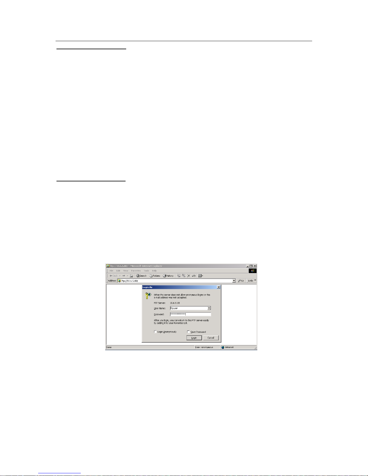
Access FTP share folder
There are two ways for you to access FTP share folder.
z IE access
Input 3016X internet intelligent storage IP address (such as 10.6.5.88) in the IE address column.
System pops up a dialogue box, please input user name and password. See Figure 3-40.
System default FTP user name is ftpuser.
Default FTP password:111111111111.
Note
There is only one FTP user: ftpuser. For security reasons, please modify your password after you
first log in.
Figure 3-40
z FTP software access
You can install a FTP software (such as LeapFTP, flashfxp) to realize FTP share.
3.6.1.4 Delete share folder
Share folder can be divided into two situations:
z Disable share property (folder still exists).
Page 43

ESS3016X User’s Manual
43
Disable SAMBA share: In share configuration interface, from the share list, click the edit
button. You can go to the edit interface. Select to disable SAMBA share and then click save
button. (See Figure 3-38)
Disable NFS share. In share configuration interface, click the edit button of the share folder
you want to delete. You can go to edit interface. Select to disable NFS share and then click
save button. (See Figure 3-38)
Disable FTP share. In share configuration interface, click the edit button of the share folder
you want to delete. You can go to edit interface. Select disable FTP share and then click
save button. (See Figure 3-38)
Note
When it is in multiple share modes, you can use either or all of the methods to disable share.
z Delete share folder completely.
In share configuration interface (See Figure 3-34), select the item from the share list and then
click corresponding delete button. The folder will be deleted permanently.
3.6.2 FTP Configuration
Click FTP configuration, the interface is shown as in Figure 3-41.
Here you can view FTP configuration information. You can set FTP share folder, delete FTP
share folder.
In Figure 3-41, you can see the following information:
Transmission speed (unit: KB) is 1000.
IP connected amount: each IP only allows 2 connections.
Total connection amount is 64.
Please note: When transmission speed is 0KB, it stands for there is no transmission limit.
Figure 3-41
3.6.3 Service Management
From share to service, you can see the following interface. See Figure 3-42.
Here you can enable, disable or start SAMBA, NFS, FTP, iSCSI service.
Page 44

ESS3016X User’s Manual
44
Figure 3-42
3.6.3.1 SAMBA Configuration
Enable SAMBA service: check start item and then click set button.
Disable SAMBA service. Check stop item and then click set button.
Restart SAMBA service. Check restart item and then click set button.
3.6.3.2 NFS Configuration
Enable NFS service: check start item and then click set button.
Disable NFS service, check stop button and then click set button.
Restart NFS service: check restart button and then click set button.
3.6.3.3 FTP Configuration
Enable FTP service: check start item and then click set button.
Disable FTP service: check stop button and then click set button.
Restart FTP service: check restart button and then click set button.
3.6.3.4 iSCSI Configuration
Enable iSCSI service: check start item and then click set button.
Disable iSCSI service: check stop button and then click set button.
Restart iSCSI service: check restart button and then click set button.
3.6.3.5 CMS Configuration
Enable CMS service: check start item and then click set button.
Disable CMS service: check stop button and then click set button.
Restart CMS service: check restart button and then click set button.
3.7 Status Management
Status management is to view system log, system status and system upgrade.
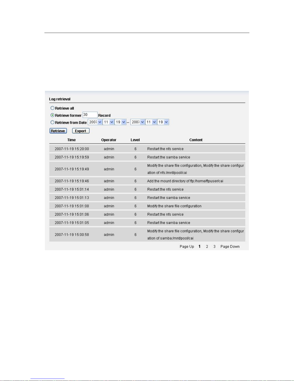
3.7.1 Log Review
Page 45
ESS3016X User’s Manual
45
Click log view button, you can see the following interface. See Figure 3-43.
Log search consists of three modes:
z Search all logs: click search button you can see all logs.
z Search the recent logs: input log amount you want to view in the () and then click search
button. Please note system take current time as starting time.
z Search the log during the specific time period. You can input a time period in the interface to
search the log you want to view.
z System also supports log export function.
Figure 3-43
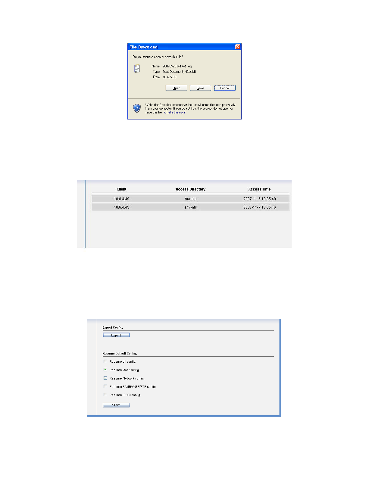
Click export button, system pops up the following interface. See Figure 3-44.
Click save button and specify the path. You can download the logs to your local PC.
Please note administrator can export and review all logs, ordinary user can only review and
export the operation logs of his own.
Max log amount is 1000. System will automatically overwrite the previous log files once the log
exceeds 1000 items.
Page 46
ESS3016X User’s Manual
46
Figure 3-44
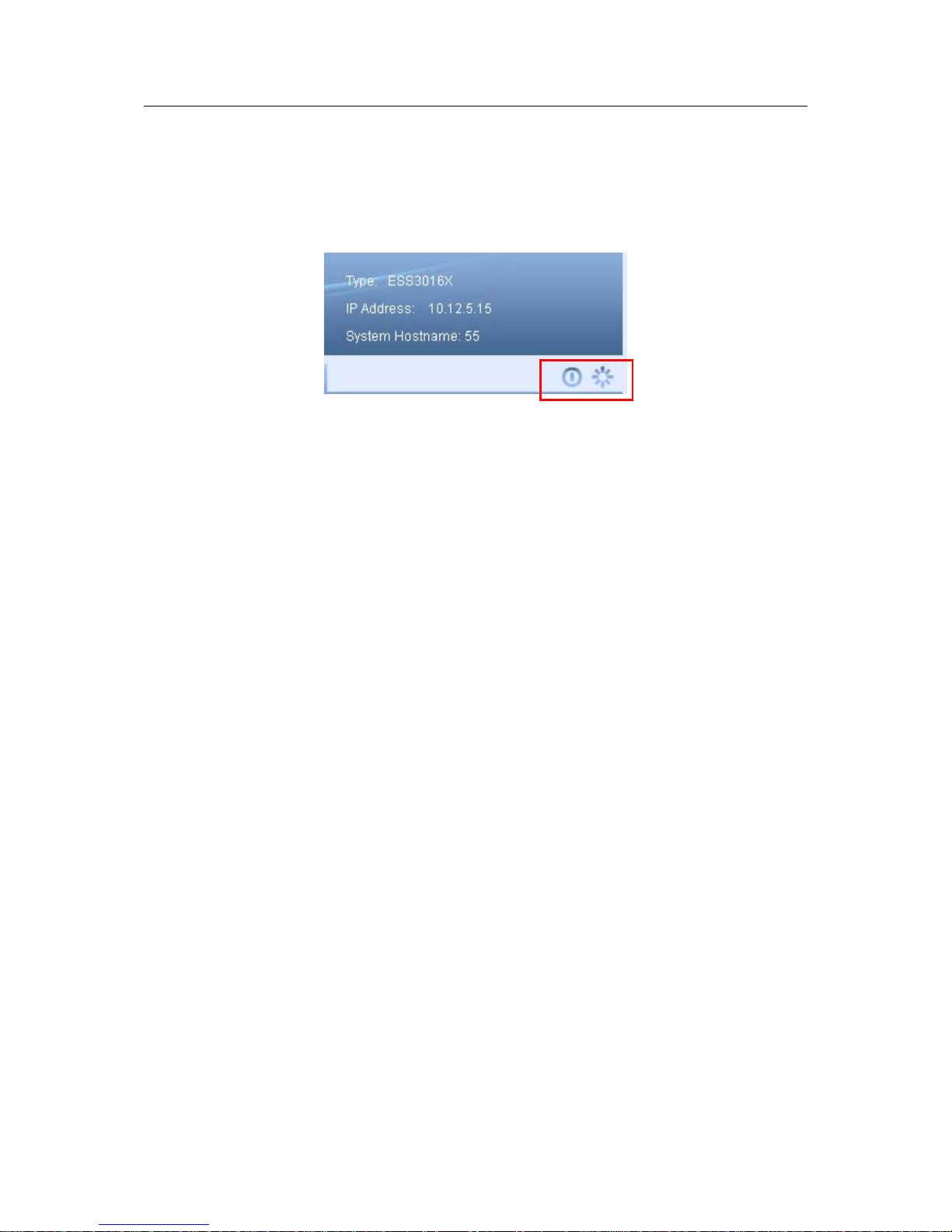
3.7.2 Service Status
Click service status, you can see an interface is shown as in Figure 3-45.
In Figure 3-45, host (IP address 10.6.5.49) is accessing SAMBA share folder. Here you can also
see accessing time.
Figure 3-45
3.7.3 Resume
Resume interface is shown as in Figure 3-46.
This function allows you to export the configuration file and then send back the file to the
engineer to analyze the error reason.
Figure 3-46
Page 47
ESS3016X User’s Manual
47
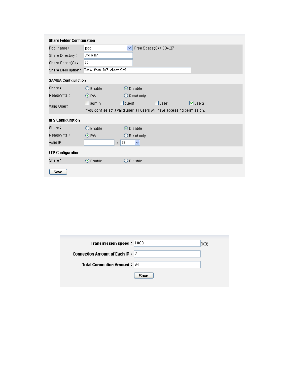
3.8 Reboot/Shut down
You can see log out button in any interface. It is on the top right corner. See Figure 3-47.
Click reboot button you can restart the device.
Click shutdown button you can turn off the system.
Figure 3-47
Page 48

ESS3016X User’s Manual
48
4 Create ESS3016X Device NAS Share
This chapter is to help you quickly create SAMBA, NFS and FTP share and provide share
service.
4.1 Quickly Create NAS Share Process
Here is a flow chart for SAMBA and NFS share creation.
Figure 4-1
4.2 NAS Share Example
4.2.1 SAMBA Share Creation
4.2.1.1 Admin user login
In the log in interface, you can input administrator name and password to log in. See Figure 4-2.
Figure 4-2
Default account is:
z User name: admin.
z Password:88888888888.
From the system management, select user management. See Figure 4-3.
Administrator logs in
Create a user
Create RAID device
Create storage pool
Share configuration
Enable share service
Page 49

ESS3016X User’s Manual
49
Figure 4-3
And then click add button, you can see an interface is shown as in Figure 4-4.
Figure 4-4
Please note, system has three valid accounts:
z admin (system administrator ), 8888888888
z guest(ordinary user), 666666666666
z ftpuser(ftp user),111111111111
4.2.1.2 Create system user
Here you can create a user such as user1. See Figure 4-5.
Figure 4-5
4.2.1.3 RAID device configuration (Here we take RAID5 as an example)
Page 50

ESS3016X User’s Manual
50
From disk management, select RAID configuration. See Figure 4-6.
Figure 4-6
And then click add button in Figure 4-7.
Figure 4-7
You can see an interface is shown as in Figure 4-8.
Here you can select RAID5 device (at least four disks)
Page 51

ESS3016X User’s Manual
51
Figure 4-8
Note
Before using devices here, please enable RAID5 device synchronization process.
4.2.1.4 Storage pool configuration
From disk management, select storage pool configuration. See Figure 4-9.
Figure 4-9
Click add button in Figure 4-10.
Page 52

ESS3016X User’s Manual
52
Figure 4-10
Now you can configure storage pool. See Figure 4-11.
Here you can see raid5 device disk15 constitutes storage pool1.
Figure 4-11
4.2.1.5 Share folder configuration
From share management, select share manage. See Figure 4-12.
Page 53

ESS3016X User’s Manual
53
Figure 4-12
And then in Figure 4-13, click add button.
Figure 4-13
In Figure 4-14, please follow the steps below.
z Select one storage pool to create a share folder(such as pool)
z Input SAMBA share folder name.(DVRch6)
z Set share folder total space(100G)
z Input share content description(data from DVR channel 6)
z Select a valid user (such as user1). If there is no valid user, any user can access current
share folder.
z Enable SAMBA share service.
z Enable SAMBA read-write right.
z Enable NFS share service.
z Click save button.
Page 54

ESS3016X User’s Manual
54
Figure 4-14
4.2.1.6 Enable share service.
From share to service. In Figure 4-15, you can enable SAMBA service and then click set button.
Figure 4-15
4.2.2 NFS Share Creation
Page 55

ESS3016X User’s Manual
55
The steps are similar to create SAMBA share. There are some difference in share folder
configuration (chapter 4.2.1.5) and enable share service (chapter 4.2.1.6). Here we just introduce
NFS share folder configuration.
4.2.2.1 Configure NFS share folder.
The interface is shown as in Figure 4-16.
Here you can set the following items:
z From the dropdown list, select one storage pool to create share folder(such as pool)
z Input NFS share folder name.(DVRch7)
z Set share folder total space.(100G)
z Input share description(storage data from DVR channel 7)
z Disable SAMBA share.
z Enable NFS share
z Set NFS read-write rights.
z Valid IP setup.
z Click save button. In Figure 4-16, 10.6.0.0 means the Linux users of IP addresses ranging
from 10.6.0.0 to 10.6.255.255 can access current NFS share folder. 16 is a way to represent
subnet mask, it stands for 255.255.0.0.
Note: If you have created RAID device and storage pool, you can directly create SAMBA or NFS
share folder.
Figure 4-16
4.2.3 FTP Share Creation
Page 56

ESS3016X User’s Manual
56
From the above processes, you can see FTP share creation steps are difference from SAMBA
share creation and NFS share creation. There is no need for you to create a user, because there
is only one FTP user (ftpuser). Its user name is ftpuser and password is 111111111111. For
security reasons, please modify your password after you first log in.
Here we’d like to talk about the step four (share configuration) and the step five (FTP
configuration). See Figure 4-17.
Figure 4-17
z FTP share folder configuration
In Figure 4-18, you need to configure the following information.
1).From the dropdown list, select the pool name such as pool.
2).Input share directory such as DVRch7.
3).Set share space such as 50G.
4).You can input description information such as data from DVR channel-7. (It is an optional item.
You can leave it in blank.)
5).Disable SAMBA service.
6).Disable NFS service.
7).Enable FTP service.
8).Click save button.
Administrator logs in
Create RAID device
Create storage pool
Share configuration
FTP configuration
Enable share configuration
Page 57
ESS3016X User’s Manual
57
Figure 4-18
z FTP configuration
In Figure 4-19, you need to set transmission speed, connection amount of each IP and total
connection amount.
Note:
IF there is created RAID device and storage pool, you can create SAMBA, NFS and FTP share
folder directly.
Figure 4-19
Page 58

ESS3016X User’s Manual
58
5 Quickly Create ESS3016X Device iSCSI Share
5.1 Quickly Create ISCSI Share Process
Figure 5-1
5.2 iSCSI Share Example
From the above processes, you can see the first four steps are identical with SAMBA share of
NAS share creation processes and the sixth step is also similar. Here we just talk about the step
five.
iSCSi configuration
From iSCSI configuration, select iSCSI configuration. See Figure 5-2.
Figure 5-2
In Figure 5-3, click add button.
Administrator logs in
Create a user
Create RAID device
Create storage pool
iSCSI configuration
Enable iSCSI share service
Page 59

ESS3016X User’s Manual
59
Figure 5-3
In Figure 5-4, you can set the following items:
z Input iSCSI share device name(DVRch4)
z Set iSCSI total space (200G)
z Select one storage pool to create iSCSI share device(Pool).
z Select valid user for iSCSI share device. If you do not check a valid user here. In the future
when you load iSCSI share device, you do not need to input user name and password.
z Click save button.
Figure 5-4
Page 60
ESS3016X User’s Manual
60
6 ESS3015A
Unlike those internet intelligent storage devices such as ESS3016X, ESS3015A applies to
extend network intelligent storage capacity.
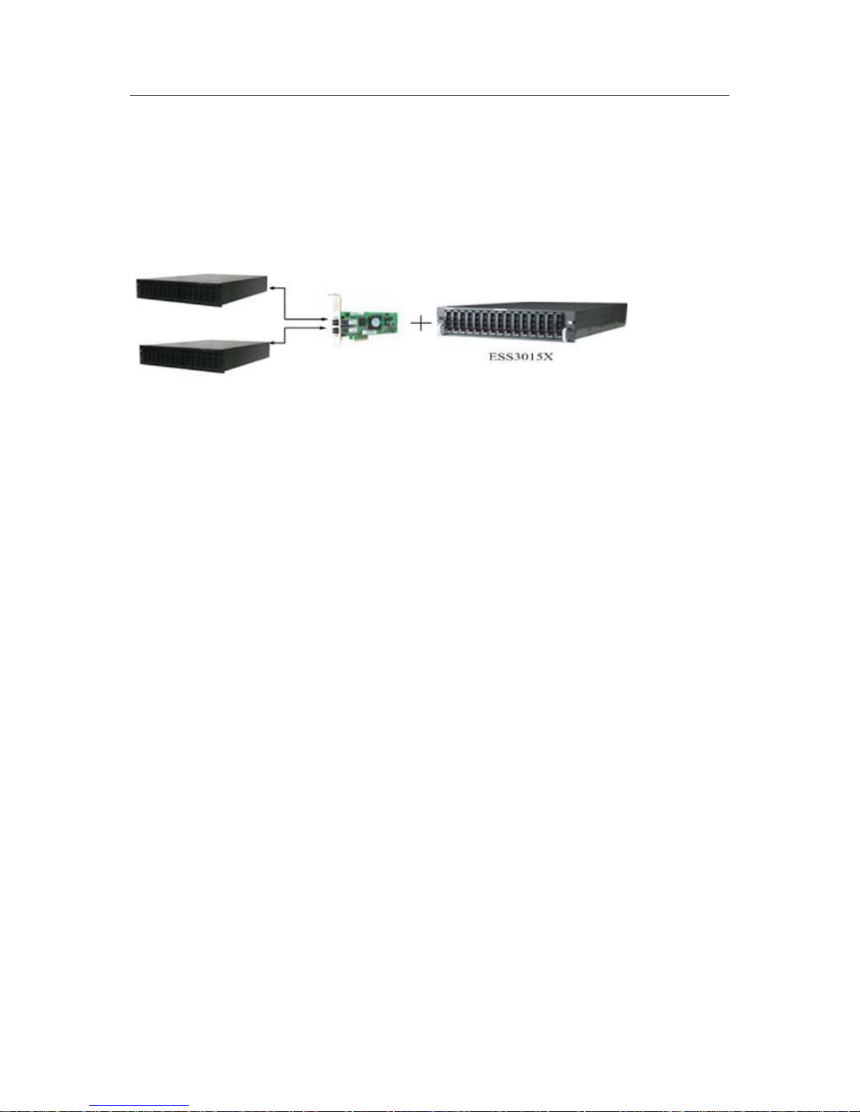
6.1 ESS3015A—ESS3016X
Disk rack connects to HBA via miniSAS cable. HBA connects to ESS3016X internet intelligent
storage device via PCI or PCI-X slot. You can refer to Figure 6-1.
ESS3015A
ESS3015A
Figure 6-1
One ESS3016X device can connect to two HBA and one HBA can connect to two ESS3015A
devices. One ESS3015A can install 15 SATA disks. So ESS3015A device can effectively
extend ESS3016X internet intelligent storage device capacity.
In this chapter, we talk about how to extend ESS3016X internet intelligent storage device.
Though ESS3015A (disk enclosure) is an extensible device, but for ESS3016X device, it just
adds some available disks in the system. The Web operation and share application is the same
as ESS3016X. Here we merely talk about the difference.
Please note ESS3016X-A COM debug operation is the same as ESS3016X. Please refer to
appendix E.
6.1.1 Disk Management
From disk management to disk management, you can see an interface is shown as in Figure 6-2.
Here you can see there are five buttons. Host and expand 1/2/3/4. It shows current ESS3016X
connects to four disk enclosure s.
When you go to disk information interface, system just shows host rack information by default.
You can click expand rack button to view corresponding information.
Page 61
ESS3016X User’s Manual
61
Figure 6-2
6.1.2 RAID Setup
From disk management to RAID setup, you can see an interface is shown as in Figure 6-3.
System displays host rack RAID configuration information by default. You can click expand disk
rack button to view corresponding information.
Please note, though sometimes user interface just shows there is only disk rack1, you can not
say there is only one disk rack connects to current ESS3016X. If you have not created RAID
device in disk rack 2, system just shows there is one host rack and one expand rack1.
Page 62

ESS3016X User’s Manual
62
Figure 6-3
z Add RAID Setup
In Figure 6-3, click add button, you can see an interface is shown as in Figure 6-4.
Here you can select RAID type (RAID0, RAID1, and RAID5), disk rack number (host,
expand1/2/3/4) and then select disks to create a RAID device.
In this interface you can just see all the available disks, those used or malfunction disks will not
be displayed,.
Click save button after you complete adding RAID device operation.
Figure 6-4
Page 63
ESS3016X User’s Manual
63
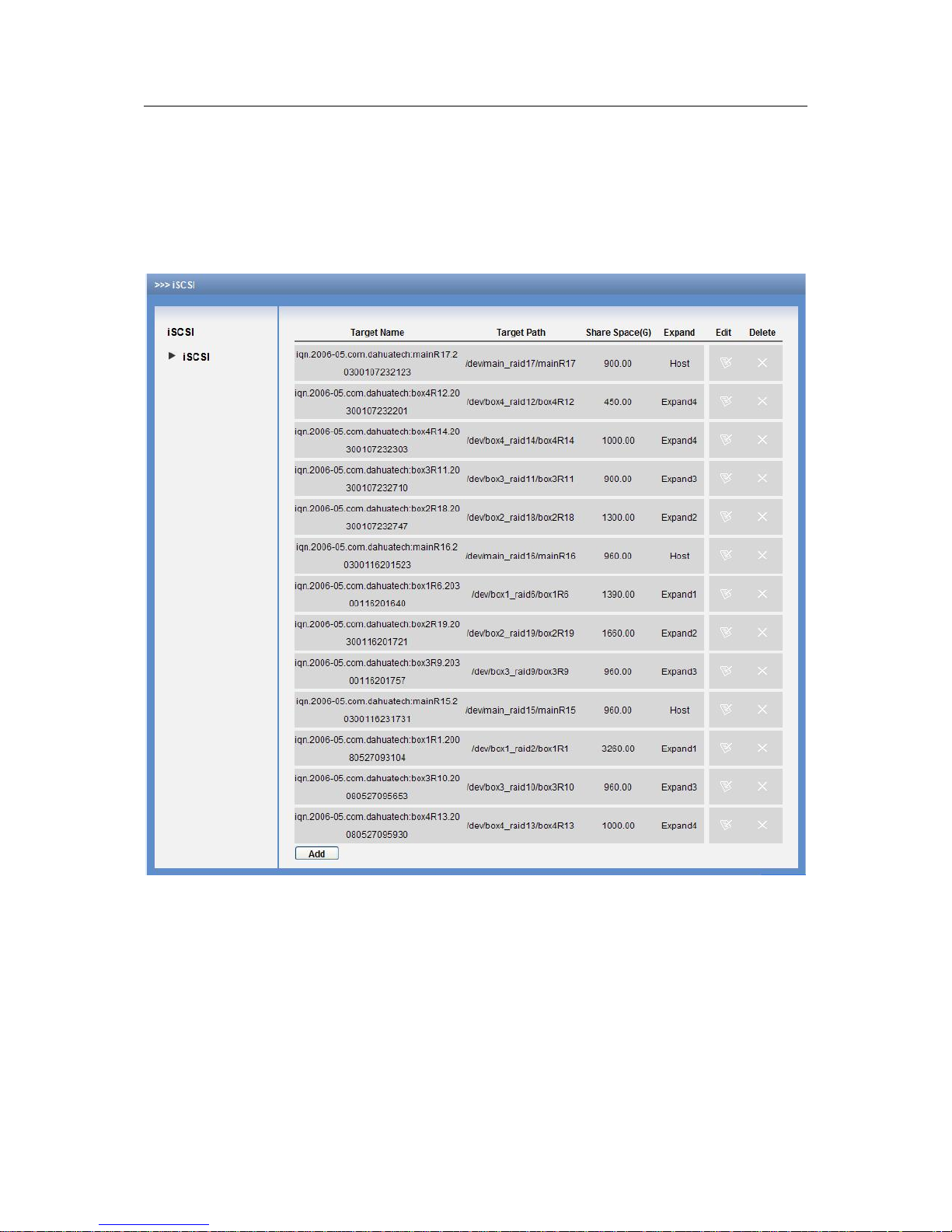
6.2 iSCSI Management
6.2.1 iSCSI Setup
From iSCSI management to iSCSI setup, you can see an interface is shown as below. See
Figure 6-5.
Here you can see there are five iSCSI share devices to provide iSCSI share service. One is in
host rack and others are in expanding rack1/2/3/4 respectively.
Figure 6-5
z Add iSCSI Share Setup
Before you create iSCSI share setup, you need to create a storage pool first!
In Figure 6-5, click add button, you can see an interface is shown as below. See Figure 6-6.
Here you need to input the following five items:
z Target name
z Configuration space (G)
z Location: You can select from the dropdown list.
z Target path: You can select from the following options.
z Valid user : there are two situations:
Page 64

ESS3016X User’s Manual
64
There is valid user: You can select either of them or both of them. The next time when you
load iSCSI share, you need to input account name and password. If you have enabled two
users, you just input either of them to log in.
There is no valid user: you do not need to input account name and password if you have not
selected a valid user here.
In Figure 6-6, you can see the following information.
You are going to create an iSCSi share device, its name is test.
This iSCSI share device total capacity is 60G.
Select host, system map all storage pool in host rack.
This iSCSI share device is created in host and its storage pool name is main_raid17. This
storage pool capacity is 1863.04G and used capacity is 900G.
There is no effective user in iSCSI device.
Figure 6-6
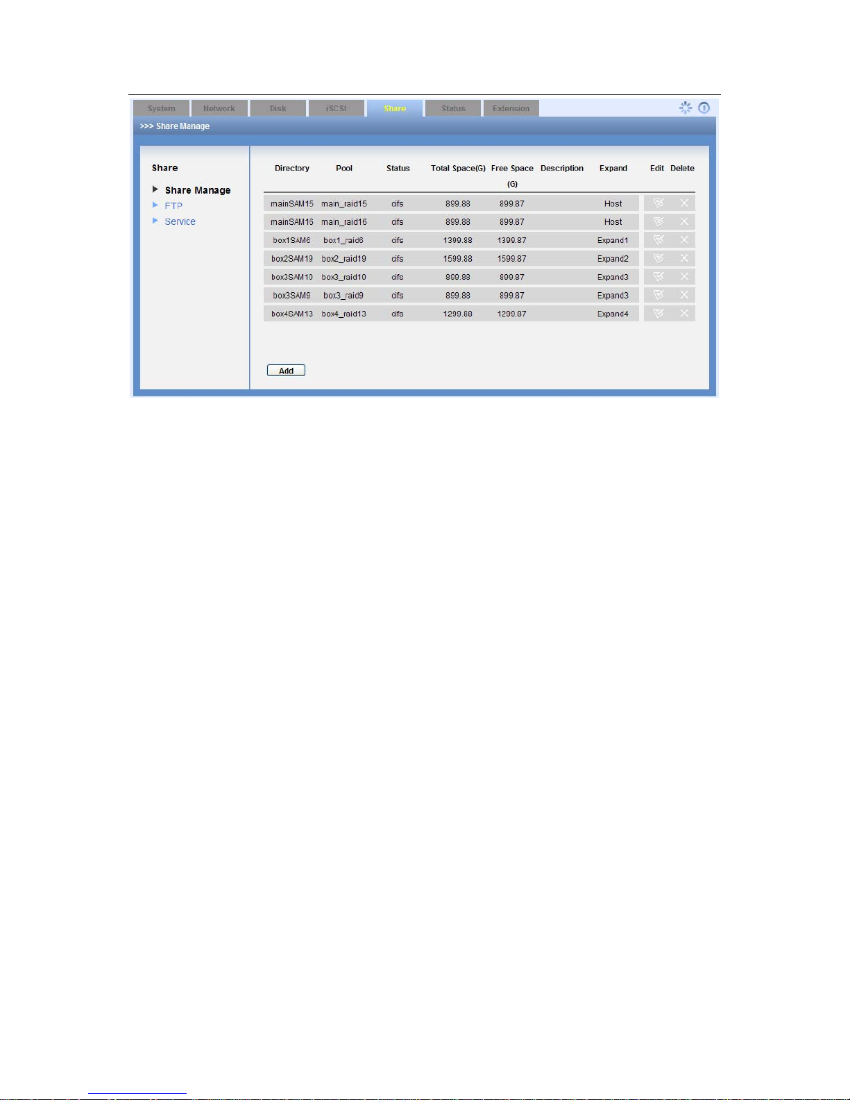
6.2.2 Share Management
6.2.2.1 Share Setup
From share management to share manage, you can see an interface is shown as in Figure 6-7.
Here you can view SAMBA, NFS and FTP share information. Here you can go to SAMBA share
operation, and you can also use this item to add share folder, edit share folder and delete share
folder.
Page 65
ESS3016X User’s Manual
65
Figure 6-7
Page 66

ESS3016X User’s Manual
66
7 Appendix A ---Terms Explanation
Here are some terms explanations in this user’s manual.
z NAS: It is the abbreviation for network attached system. It provides user file service via
network.
z SATA:It is the abbreviation for serial ATA. In current released Serial ATA 2.0, data
transmission speed can reach 300MB/second.
z SATA HDD: HDD adopts SATA standard. Some leading manufacturers such as Seagate,
Hitachi have already released SATA HDD.
z RAID: It is the abbreviation for redundant array of independent disks. It is to combine several
independent HDDs (physical HDD) to form a HDD group (logic HDD) to provide more
storage capacity and data redundancy. Now it consists of seven levels, ranging from RAID0
to RAID6.Besided, it has some basic RAID combination groups such as RAID10 (RAID0 and
RAID1, RAID 50(RAID 0 and RAID 5). Here is a comparison between RAID 0, RAID 1, RAID
5. In this manual, we call RAID5, RAID 1,RAID0 as RAID5 device, RAID1 device and RAID
0 device respectively.
z RAID0: RAID0 is so called Striped Disk Array without Fault Tolerance. It represents the
highest storage performance in RAID level. RAID0 is to read-write continue data in several
HDD. So, system data query will be performed in several HDDs at the same time.
z RAID1: It is also called Mirror or mirroring. Its aim is to maximally guarantee data safety and
restorable. RAID1 is to automatically copy user input data fully to other RAID1 HDDs.
z RAID 5: RAID5 does not backup the storage data. Instead, it will memorize data and
corresponding verification information to HDDs of RAID5. The data and verification
information will be backed up in different HDDs respectively. When data in one of the HDDs
is damaged, system can use the rest data and corresponding verification information to
restore the lost data.
RAID Advantage Disadvantage Min HDD
Amount
Applied
zone
RAID 0
z High read-
write
efficiency.
z No verification
to occupy
CPU
resources.
z Easy to
design, use
and configure
z No verification
or restore
function.
z No data error
tolerance.
z Not suitable
for harsh
environment.
2
Create and
edit video
RAID 1
z Theoretically
z , it has double
speed.
z 100% data
redundancy
function.
z Easy to
design, use
and configure.
z Low HDD use
efficient.
z High storage
cost.
z In soft RAID1
mode,
performance
descends
gravely.
2
z Financing
statistics
and data
base
financing
system.
z Need
high
maintena
nce work.
Page 67

ESS3016X User’s Manual
67
RAID 5
z High read
transmission
speed.
z Medium write
speed,
z
Considerable
low ECC HDD
data
occupatio
n.
z HDD error will
affect the
input and
output speed.
z The controller
design is a
little bit
difficult.
4
z File and
applicatio
n server,
database
server.
z Synchronization: After creating RAID 1or RAID5, before using, system needs to read-write
the HDD at a fixed speed and adopts an algorithm to calculate. This process is so called
synchronization. During the synchronization, system performance speed is very low.
z Storage pool: it is a virtual logic device. It can consist of several HDDs and RAID group. It is
a main way to realized virtual storage.
z Share folder: Local PC access the top path of the share storage space. You can create,
remove, authenticate and set valid user at the storage device. User is only allowed to
operate folder and file performance in the under-layer. According to different share protocols,
it can be divided into SAMBA share folder, NFS share folder and FTP share folder.
z SAMBA: it is MS network communication protocol software suitable for UNIX. Its core is
SMB (server message block) protocol. SMB is a client /server protocol. User can access
share file system, printer and other resources in the server via this protocol.
z NFS: It is an abbreviation for network file system. It is a distribution file system. It can allow
the local PC to use the file or peripheral devices of another PC. It is mainly used in UNIX
platform.
z iSCSI: It is a abbreviation for internet small computer system interface. It is an internet
protocol standard in Ethernet. It is an SCSI instruction set for hardware to be used in IP
protocol layer. Generally y speaking, iSCSI can realize SCSI protocol in the IP network to
realize router option in high-speed 1000M Ethernet.
z FTP: It is an abbreviation for file transfer protocol. It is a protocol of the TCP/IP protocol
group. It is to transfer file from one PC to another while it has no relationship with PC OS,
location and connection type.
z CIFS: It is an abbreviation for Common Internet File System. CIFS is an open and cross-
platform running mechanism for the user to ask for file or print service from the server. It is a
standard server message block (SMB) protocol widely used in personnel PC and work
station
z Management status: It is a device status when controller configure device via web. Actually,
when there is no error or damage, device shall be always in management status.
z Working status: It is a device status when controller access HDD via network. System is
ready to use after you configure correctly in accordance with this user’s manual. Some non-
device error (such as configuration error, hot swap error) may result in device failure. You
can configure again to boot up the device. But data loss may occur during this process.
Page 68

ESS3016X User’s Manual
68
8 Appendix B--- Disk Hot Swap Operation
Note: please implement 3016X internet intelligent storage device when RAID is in working
status.
Hot swap only be operated when RAID is in working status, otherwise it may result in data
loss in RAID device!
z Ready status: It only applies to RAID1/RAID5, e.g these disk groups are in RAID
synchronization. When disk group are in ready status, in the web configuration interface,
from disk management to RAID configuration, you can see the corresponding RAID group
status is “clean,degraded,recovering”.
z Working status: it only applies to RAID1/RAID5. It is a RAID status after synchronization.
When disk group are in ready status, in the web configuration interface, from disk
management to RAID configuration, you can see the corresponding RAID group status is
“clean,degraded,recovering”.
z Degraded status: It only applies to RAID1/RAID5. e.g the working RAID disk group status
after hot swap a disk. When RAID is in degraded status, in the web configuration interface,
from disk management to RAID configuration, you can see the corresponding RAID group
status is “clean,degraded”.
Operation example
The RAID5 and RAID1 have the same hot swap operation steps. Now we take RAID5 as an
example.
In 3016X internet intelligent storage device, there is a RAID5 disk group consists of four disks
(dsk1, disk2, disk3, disk4.). All these four disks are in working status.
Note: 3016X internet intelligent storage device support max 16 SATA disks. But for
performance and safety consideration, we recommend RAID 5 consists of four to six
disks, RAID1 consists of two to three disks.
Note: Here we just take four disks as an example. When your disk amount is more than 4,
the operation is just the same.
1). Disk hot swap example.
In web configuration interface, from disk management to disk information, you can see the
information before hot swap. See Figure 8-1.
Here you can see the following information:
z In 3016X internet intelligent storage device, disk group has four disks.
z The four disks are: dsk1, disk2, disk3, disk4.
z These four disks are corresponding to channel 1 to channel 4 respectively.
z All disks are in running status, which means there is no error.
Page 69

ESS3016X User’s Manual
69
Figure 8-1
2) In web configuration interface, from disk management to RAID configuration, you can see
current RAID device status.
Before hot swap, please make sure the disk to be hot swapped is in RAID5 (RAID1) and RAID5
(RAID1) is in working status. See Figure 8-2.
Figure 8-2
3). Log out disk to be hot swapped.
In Figure 8-2, click edit button of the corresponding RAID device. You can see an interface is
shown as in Figure 8-3.
Here you can see the following information:
z RAID 5 device md0 total space is 698.66, and it consists of four disks.
z The RAID status is in working status. (Clean mode).
z The group consists of four disks: disk1, disk2, disk3, disk4.
z There is a newly added disk list.
Check remove button after disk1 and then click save button. Now you are about to remove disk1.
Page 70

ESS3016X User’s Manual
70
Figure 8-3
4). In web configuration interface, from disk management to disk information, you can see the
disk information after hot dismantle: disk1 is in free status. See Figure 8-4.
Now there are two options:
z You can remove the disk1 from the rack.
z You can insert the disk1 into other RAID5/RAID1 in degraded mode. And then create
storage pool and share folder to provide share service.
Figure 8-4
5). In web configuration interface, from disk management to RAID configuration, you can see
RAID device status. See Figure 8-5.
Page 71

ESS3016X User’s Manual
71
After hot swap disks, RAID5 device from working status to clean, degraded status. Current
RAID5 disk group can still work properly.
Figure 8-5
6). Hot swap disk
In web configuration interface, from disk configuration to disk configuration, you can see the disk
status. Disk3 corresponding channel number is channel 3(Please refer to Figure 8-4), now you
can remove the corresponding disk from the rack.
7). In web configuration interface, from disk configuration to disk configuration, you can see the
RAID status information. See Figure 8-6.
Figure 8-6
8).from disk to RAID, you can view the RAID device status after hot swap. See Figure 8-7.
The RAID status after hot swap is the same with that before hot swap.
Figure 8-7
Now you can refer to the following part for inserting a new disk.
Hot insert disk example.
Note: The hot insert operation only applies to the disk group that has been hot swapped.
It is to guarantee data safety.
1). In web configuration interface, from disk configuration to disk configuration, you can see the
following information. See Figure 8-8.
Page 72

ESS3016X User’s Manual
72
Figure 8-8
2). Insert the disk directly to the idle disk channel of 3016X internet intelligent storage and
memorize the disk channel name (such as disk1). In this example, we are going to insert the
disk1 that just was removed.
From disk management to disk information, you can review disk information before hot swap.
And then check disk information again after hot swap.
Compare the information before and after hot swap. You can see before hot swap, there are
three disks: dksk2, disk3, disk4. After hot swap, you can see the there are four disks: disk2, disk3,
disk4, disk1. Now you can see the newly inserted disk name is disk1.
3). In web configuration interface, from disk configuration to disk information, you can see the
disk information. See Figure 8-9.
Figure 8-9
4). In web configuration interface, from disk configuration to RAID configuration, you can see the
following RAID device status. See Figure 8-10.
Since current disk group md4 is in degraded status, you can add disk now.
Figure 8-10
5). Insert hot swap disk.
In Figure 8-10, click edit button, you can see an interface is shown as in Figure 8-11.
Now please check the add button and then click save
Please note, hot swap operation only applies to degrade RAID1/RAID5
RAID begins synchronization again after hot swap.
Page 73
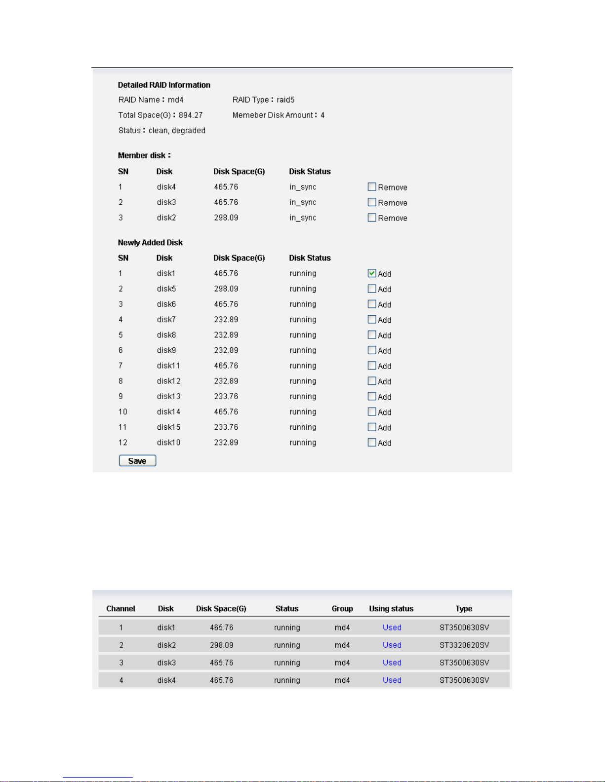
ESS3016X User’s Manual
73
Figure 8-11
Note:
Since newly added disk information take “disk volume” as a symbol (such as disk1), so in
the step (2) please memorize hot swap disk name.
6). In web configuration interface, from disk configuration to disk configuration, you can see the
disk information. See Figure 8-12.
Figure 8-12
Page 74

ESS3016X User’s Manual
74
7). In web configuration interface, from disk configuration to RAID configuration, you can see the
following RAID device status. See Figure 8-13.
Figure 8-13
Note
After hot swap, RAID5 device status is from “degrading” to “recovering” and begins
synchronization.
During the hot swap process, system data will not be damaged.
Page 75

ESS3016X User’s Manual
75
9 Appendix C ---SAMBA Share Implementation in Windows
SAMBA and central management implementation
3016X internet intelligent storage device provides SAMBA share just like a network disk. When it
works with central management software, you need to map it to local disk partition. Please follow
the steps below.
1).Access the SAMBA share of the 3016X internet intelligent storage device.
Open IE browser and input 3016X internet intelligent storage device IP address in the address
column as \\10.6.5.88. System will pops up a dialogue box for you to input user name and
password. Now you can see the following interface. See Figure 9-1. There is a SAMBA share ftp.
Figure 9-1
2).set network disk
Right click ftp and then select map network drive. See Figure 9-2.
Figure 9-2
Page 76
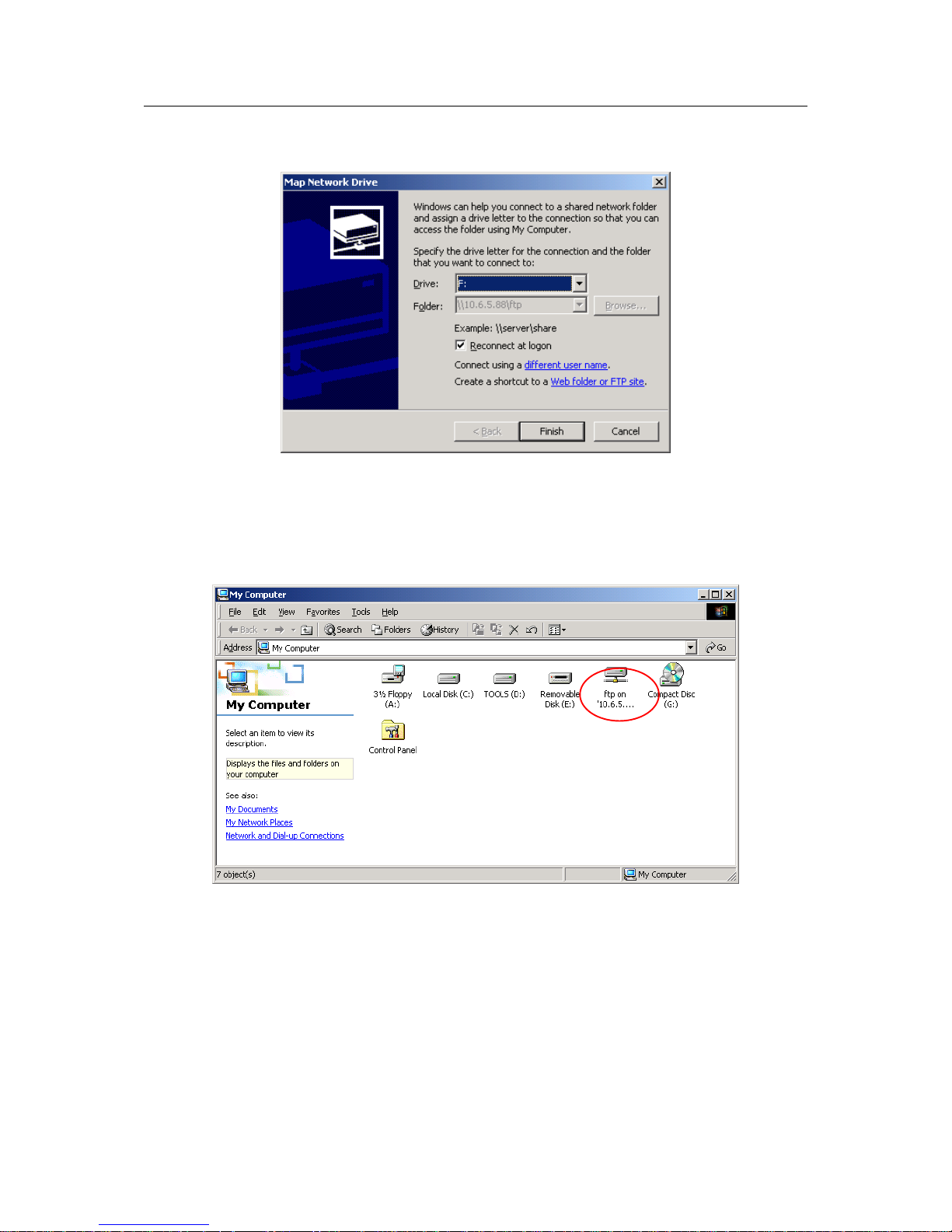
ESS3016X User’s Manual
76
System pops up the following dialogue box. See Figure 9-3. You can select drive symbol (A:--Z:)
and then click finish button.
Figure 9-3
3).View local PC disk.
Open my computer, you can see network driver is not empty, which means the map network
drive is successful. See Figure 9-4.
Figure 9-4
Note: current share folder just like local PC F disk. The central management software can save
storage path as :“F:/” .
Page 77
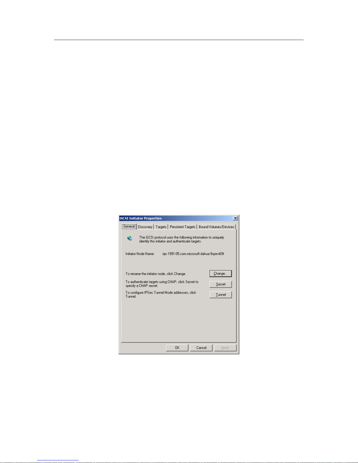
ESS3016X User’s Manual
77
10 Appendix D---iSCSI Application in MS Windows
iSCSI connection in windows system
3016X internet intelligent storage device can provide iSCSI share. But you need to install
corresponding software to support such a kind of function. Here we introduce iSCSI connection
in MS Windows: the iSCSI Initiator installation and use so that you can use iSCSI share of the
3016X internet intelligent storage device.
There are three basic steps:
Install MS iSCSI Initiator software
Connect to iSCSi share of 3016X internet intelligent storage device via iSCSI Initiator.
Map iSCSI storage as local disk. Partition and format the disk
iSCSI Initiator software
Please go to Microsoft official website download iSCSI Initiator software. Please follow the
installation shied to install the software. You can see a MS iSCSI Initiator icon on the desk top.
Connect to iSCSi share of 3016X internet intelligent storage device via iSCSI Initiator.
1).Double click MS iSCSI Initiator icon on the desktop. You can see an interface is shown as
below. See Figure 10-1.
Figure 10-1
2) Click Discovery, you can see an interface is shown as in Figure 10-2.
Page 78
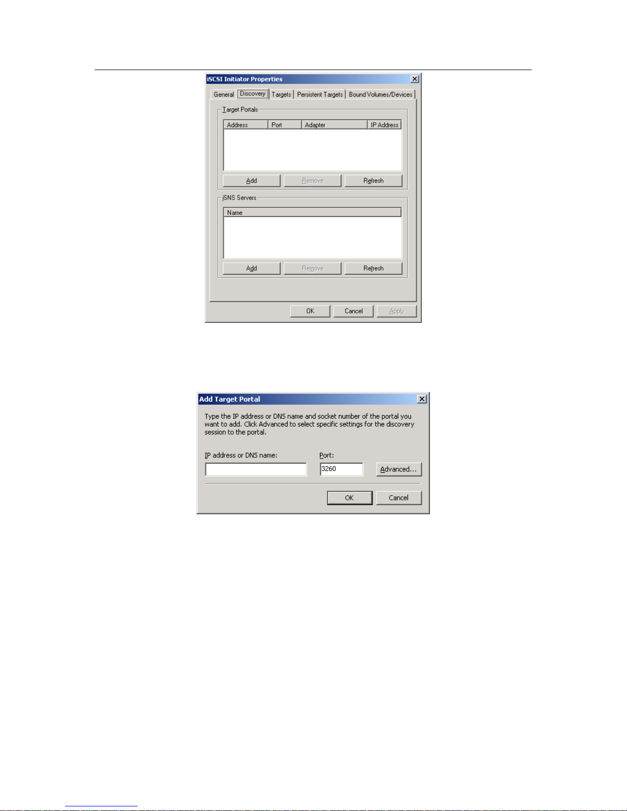
ESS3016X User’s Manual
78
Figure 10-2
3). Click add button, input 3016 internet intelligent storage device IP address and then click Ok
button. See Figure 10-3.
Figure 10-3
4) Click target button to view 3016 internet intelligent storage device share situation. See Figure
10-4. Here you can see there are two share devices and their statuses are both inactive.
Page 79
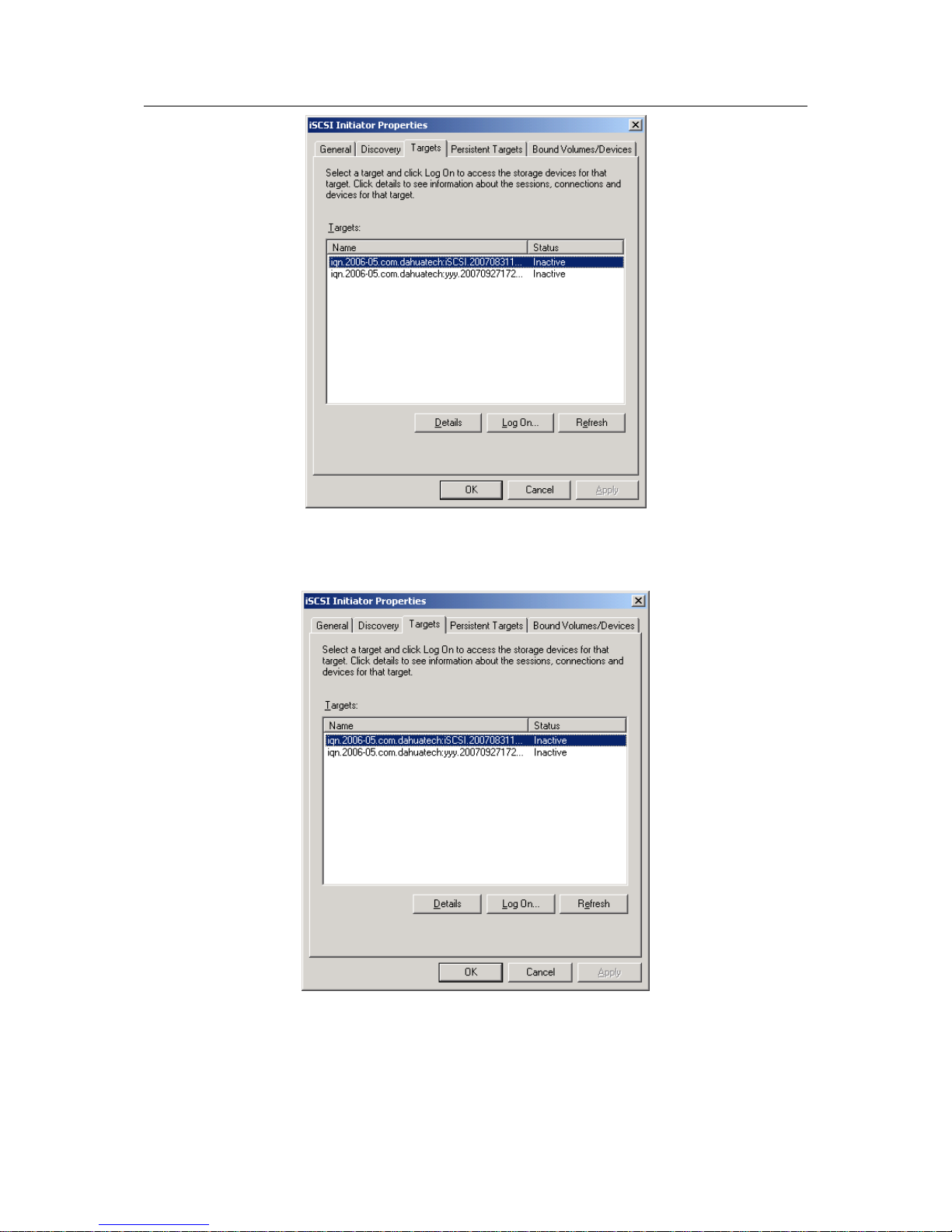
ESS3016X User’s Manual
79
Figure 10-4
5). In Figure 10-4, select one iSCSI share and then click “Log on” button. See Figure 10-5.
Figure 10-5
Please enable auto connect function. See Figure 10-6.
Page 80

ESS3016X User’s Manual
80
Figure 10-6
6).Now there is two situations:
z When ISCSI share device has no valid user
Click OK button, now you can see the selected iSCSI device status becomes active.
z When iSCSI has a valid user.
Click advance button, system pops up a dialogue box. Here you check “CHAP logon information”
and then input user name and password. Click OK, you can access iSCSI share now. See Figure
10-7.
Figure 10-7
Map iSCSI of 3016X internet intelligent storage device as local disk
1).Right-click my computer icon and then click manage item. Select disk management on the left
side. You can see an interface is shown as in Figure 10-8.
Page 81

ESS3016X User’s Manual
81
Figure 10-8
2).In Figure 10-8, click disk 2 and then click initialize disk. See Figure 10-9.
Figure 10-9
3). Right-click “12.00GB unallocated” and then select new partition. See Figure 10-10.
Page 82
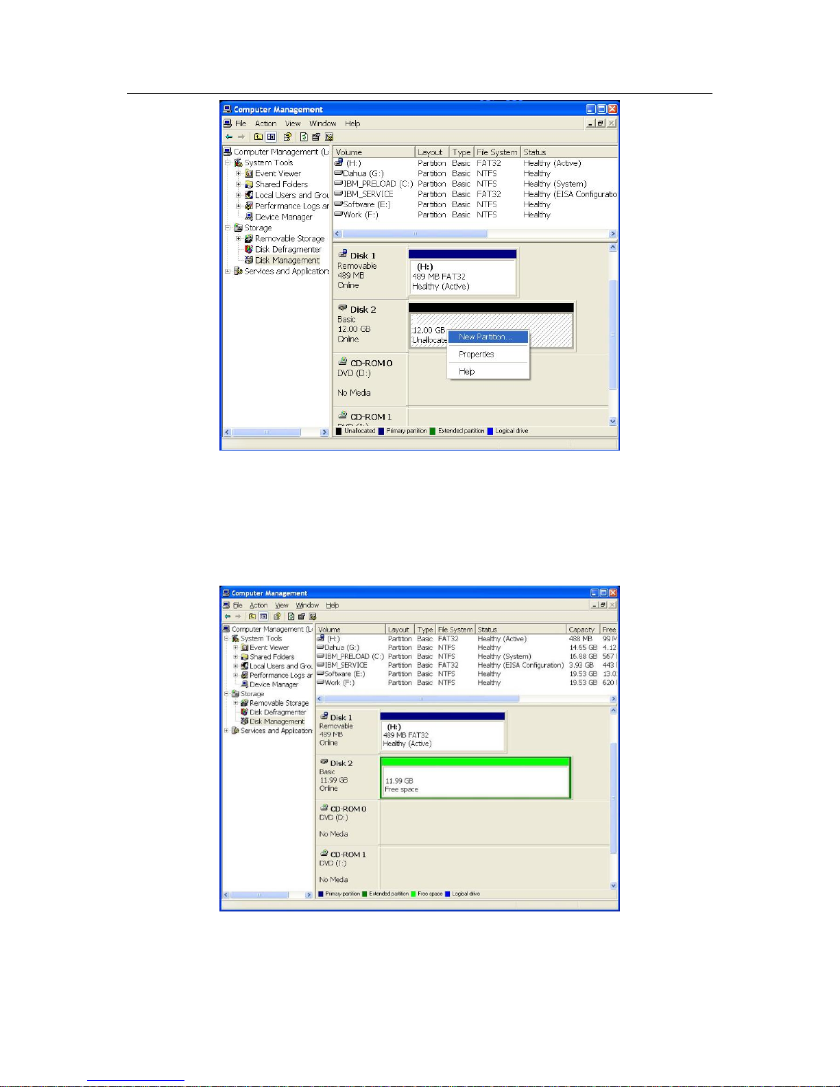
ESS3016X User’s Manual
82
Figure 10-10
4). Please follow the instructions to set and format the disk.
5). After formatting, the iSCSI share will be displayed as newly added volume and has its own
driver number. See Figure 10-11. Now you can use iSCSI device.
Please note Disk2 is the newly added iSCSI device.
Figure 10-11
Page 83
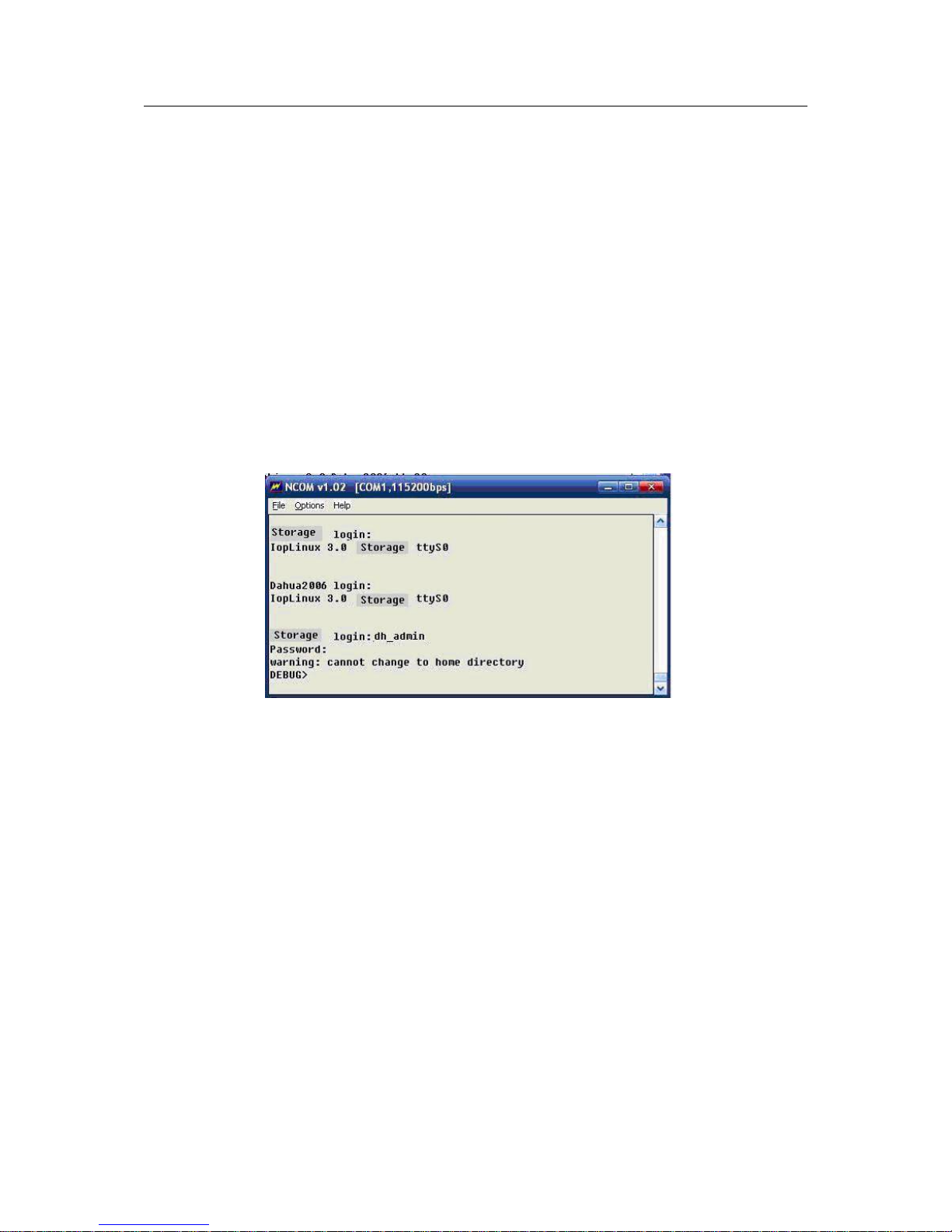
ESS3016X User’s Manual
83
11 Appendix E—COM COMMAND
ESS3016X internet intelligent storage device provides serial port Debug command for
administrator. It is to help you deal with some situation such as forgetting admin password or IP
address abnormal phenomena.
You can follow the steps listed below.
1).Connect ESS3016X device to serial port of PC or industrial computer.
2).Configure serial port terminal tools of PC (industrial computer).
3).Log in as “dh_admin” and then go to the debug command line interface.
4).Debug command operation
Here we introduce the step two to step four.
z Log in as “dh_admin” and then go to the debug command line interface
After you finish setting in Figure 11-1, please click Enter button. Now system pops up a dialogue
box for you to input user name (dh_admin) and password (debug). You can see an interface is
shown as in Figure 11-1. It is a debug command line interface.
Figure 11-1
z Debug command operation
Input command “help” after debug>, you can see an interface is shown as in Figure 11-2.
In Figure 11-2, you can see Debug command line provides five command operations:
Input “help” after “DEBUG>”, you can see Debug command list.
Debug command lien provide five command operations:
help: Display corresponding information about Debug command. Command format: help.
netshow: Here you can view current IP address, command format: netshow.
netset: Reset system IP address. Command format: netset, IP address, subnet mask.
adminpwdset: Restore factory default password (888888888888). Command format:
adminpwdset.
reboot: Reboot system. Command format: reboot.
Please note, reset system IP address command “netset” consists of two command parameter: IP
address and subnet mask. There is no gateway parameter. You need to go to web interface to
set system default gateway.
Page 84

ESS3016X User’s Manual
84
Figure 11-2
Here we take netshowas an example.
In debug command line, input netshow and then click Enter button.
Now you can see an interface is shown as in Figure 11-3.
You can see the information after bond0. In Figure 11-3, you can see system IP address is
10.6.5.81.
Note:
Netset is to reset system IP address and it has two command parameters: parameter 1 is to set
the IP address and parameter 2 is subnet mask. Since there is no default gateway, you need to
log in web and then set system default gateway after setting IP address.
Page 85

ESS3016X User’s Manual
85
Figure 11-3
Slight difference may be found in user interface.
All the designs and software here are subject to change without prior written
notice.
Please visit our website for more information.
 Loading...