

Dahua EBW8600, EBW81200 Quick Start Manual

HD Fisheye Panorama N et work Camera Q uick S t art Guid e
Version 1. 1.0
i

Welcome
Thank you for purc ha sin g o ur net work came ra!
This user’s manual is designed to be a reference tool for your system.
Please read the following saf eguard and wa r nings car efully befo r e you use this series
product!
Please keep this use r ’s manual we ll for future refer ence!
1
.
Electrical safety
All installation and operation here should confor m to yo ur local elect r ic al safety code s .
The power shall conf orm to the r equirement in the SELV ( S afety Ex tra Low Voltage) and
the Limited po wer source is r ate d 12V DC in t he I E C60950-1. This series product
supports PoE too.
Note: Do not connec t t hese t wo power supplyin g sources to t he device at the same
time; it may result i n devic e damage!
We as s ume no liability or re s ponsibility for all t he fire s or electrical shock c aused by
improper ha ndling o r ins tallation.
We are not liable for any problems caused by unauthorized modification or attempted
repair.
2
.
Transportat i on security
Hea v y s tress, viole nt vibration or water s plash ar e not allowe d dur ing transportat ion,
sto r age a nd ins tallation.
3
.
Installation
Do no t apply po wer t o the camera before c ompleting installation.
Please inst all the pr oper powe r c ut-off device during the installation con nection.
Always fo llow the instruc tion guide the m anufa c turer recomm ended.
4
.
Qualified engin eers needed
All t he examination and repair work should be done by the qua lified service engi neers .
We are not liable for any problems caus ed by unauthorized m odif ic ations or at tempt ed
repair.
5
.
Environment
This series network camera should be installed in a cool, dry place away from direct
sunlight, inflammable, explosive subs tances and e tc.
i

Please keep it away from the electrom agnet ic r adiation object and environm ent.
Please make sure the CCD (CMOS) component is out of the radiation of the laser beam
device. Ot herwise it may result in CCD ( CM OS) opt ical c omponent damage.
Please keep the sound ventilation.
Do no t allow the water and other liquid fa lling into the c amer a.
Thunder-proof device is recommended to be adopted to better prevent thunder.
The grounding holes of the product are recommended to be grounded to further enhance
the reliability of the camera.
6. Daily Maintenance
Please shut down the devic e and then unpl ug the po wer cable be fore you begin da ily
maintenance work.
Do no t touch the CCD ( CM OS) optic compone nt. Y ou can use the blower to clea n the
dust on the lens surface.
Always use the dr y s oft clo th to clean the device . If ther e is too much dust, plea s e use
the water to dilute t he mild deter gent firs t and then use it to clean the device. Finally use
the dry c loth to clean the device.
Please put the dustpr oof c ap to pr otect the CCD (CMOS) component when you do not
use the camera.
Dome enclo s ur e is the optical component, do not touch the enclosure when you are
insta lling the device or c lean the enclosure when you are doing maintenanc e wo r k .
7. Accessories
Be sure to use all the accessories recommended by manufacturer.
Bef ore installation, please open the package and check all the co m ponents are included.
Contact your local ret ailer AS AP if som ething is broken in you r packa ge.
Accessory Name
Amount
Network Camera 1
Quick Start Guide
1
Insta llat io n Acce ssories Bag 1
CD 1
ii

Table of Contents
1 Structure.......................................................................................................... 1
1.1 Device Exter nal Cable ...................................................................... 1
1.2 Dimensions ........................................................................................ 2
1.3 Bidirectional Talk ............................................................................... 2
1.3.1 Device-end to PC-end ................................................................ 2
1.3.2 PC-end to Device-end ................................................................ 3
1.4 Alarm Setup ....................................................................................... 3
2 Installation ....................................................................................................... 4
2.1 General Installation ........................................................................... 4
2.2 Device I nstallation Steps .................................................................. 4
2.3 Micro SD Card Installation ................................................................ 5
2.4 Manual Zoom Lens Focus Operation............................................... 6
3 Quick Configuration Tool ............................................................................... 7
3.1 Overview ............................................................................................ 7
3.2 Operation ........................................................................................... 7
4 Web Operation ............................................................................................... 9
4.1 Network Connection .......................................................................... 9
4.2 Login and Main I nterfa ce .................................................................. 9
4.3 Panorama Funct io n on Web ........................................................... 11
4.3.1 Installation Mode....................................................................... 11
4.3.2 Display Mode ............................................................................ 11
Appendix Toxic or Hazardous Materials or Elements....................................... 12
iii
1 Structure
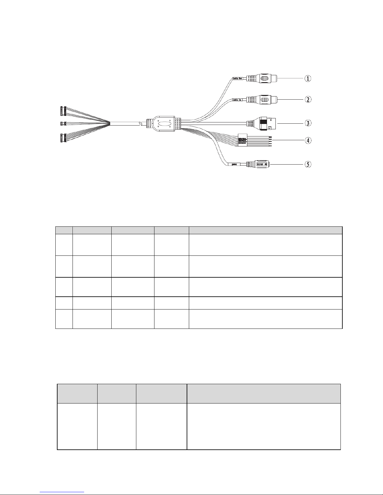
1.1 Device External Cable
Figure 1- 1
The device external cable is shown in Figure 1- 1.
Please refer to Sheet 1-1 for corresponding information about e x terna l c able funct ions.
NO.
Port
Port Name
Connector
Functio n De scr ipt io n
1
AUDIO
OUT
Audio output
port
RCA Output audio signal to the speakers.
2 AU DIO IN
Audio input
port
RCA
Input audio signal, receive the analog audio signal
fro m the sound pick-up.
3 LAN
Network port
Ethernet
port
Connect to standard Ethernet cable.
4 I/O I/O port - Conne c t I/ O port
5 POWER
Power input
port
- Conne c t DC 12V power, input pow er
Sheet 1-1
Please refer to Sheet 1-2 for co r r esponding information about I/O port functions.
Port Name
Cable
Number
Cable Port
Name
Functio n De scr ipt io n
I/O port 1 ALARM_NO
Alarm output port. It is to output the alarm signal
to the alarm device.
NO:Normal open a larm output por t.
This port needs to be used with ALARM_COM
port
1
 Loading...