

Page 1

L3 Manage Switch
CLI Configuration Manual
(Applicable to DH-PFS6428-24T)
Page 2

Contents
CLI Configuration Manual ..................................................................................................................... 1
1. System Status Commands ....................................................................................................... 7
1.1 Mode Description ............................................................................................................. 7
1.2 System information .......................................................................................................... 8
Function Brief .................................................................................................................. 8
1.2.1 show version .......................................................................................................... 8
1.2.2 show clock ............................................................................................................. 8
1.3 Log information ................................................................................................................. 9
Function Brief .................................................................................................................. 9
1.3.1 show logging .......................................................................................................... 9
1.4 Port statistics .................................................................................................................... 9
Function Brief .................................................................................................................. 9
1.4.1 show interface ..................................................................................................... 10
1.5 LACP status .................................................................................................................... 10
Function Brief ................................................................................................................ 10
1.5.1 lacp state .............................................................................................................. 10
1.6 View route ....................................................................................................................... 11
Function Brief ................................................................................................................ 11
1.6.1 show ip route ....................................................................................................... 11
1.7 ERPS-RING status ........................................................................................................ 12
Function Brief ................................................................................................................ 12
1.7.1 show erps ............................................................................................................. 12
1.8 Power status ................................................................................................................... 12
Function Brief ................................................................................................................ 12
1.8.1 show power .......................................................................................................... 12
2. System Setting Commands .................................................................................................... 13
2.1 IP config ........................................................................................................................... 13
Function Brief ................................................................................................................ 13
2.1.1 ip address ............................................................................................................ 13
2.1.2 ip address dhcp ................................................................................................... 13
2.1.3 ip address old_ip ................................................................................................. 14
2.1.4 show interface ..................................................................................................... 14
2.2 User config ...................................................................................................................... 15
Function Brief ................................................................................................................ 15
2.2.1 username name .................................................................................................. 15
2.2.2 show user ............................................................................................................. 16
2.3 Time setting ..................................................................................................................... 16
Function Brief ................................................................................................................ 17
2.3.1 sntp enable|disable ............................................................................................. 17
2.3.2 sntp unicast-server ............................................................................................. 17
2.3.3 sntp auto-sync timer ........................................................................................... 18
2.3.4 sntp connect ........................................................................................................ 18
2.3.5 sntp timezone set ................................................................................................ 18
2.3.6 local-time date ..................................................................................................... 19
3. Port configuration commands ................................................................................................ 20
3.1 Port config ....................................................................................................................... 20
Function Brief ................................................................................................................ 20
3.1.1 duplex ................................................................................................................... 20
3.1.2 speed .................................................................................................................... 21
3.1.3 flow-control .......................................................................................................... 21
3.1.4 shutdown .............................................................................................................. 22
3.1.5 description ............................................................................................................ 22
3.2 Rate limit ......................................................................................................................... 22
Function Brief ................................................................................................................ 22
Page 3

3.2.1 rate-limit ................................................................................................................ 23
3.3 Port mirroring .................................................................................................................. 23
Function Brief ................................................................................................................ 23
3.3.1 monitor.................................................................................................................. 23
3.4 Link aggregation ............................................................................................................. 24
Function Brief ................................................................................................................ 24
3.4.1 trunk ...................................................................................................................... 24
3.4.2 load-balance ........................................................................................................ 25
3.4.3 lacp enable | disable ........................................................................................... 25
3.4.4 lacp active | passive ........................................................................................... 26
3.4.5 lacp key ................................................................................................................ 26
3.4.6 lacp port-priority .................................................................................................. 27
3.4.7 example ................................................................................................................ 27
4. Advanced configuration commands ...................................................................................... 29
4.1 VLAN config .................................................................................................................... 29
Function Brief ................................................................................................................ 29
4.1.1 switchport mode .................................................................................................. 30
4.1.2 switchport pvid .................................................................................................... 30
4.1.3 switchport trunk|hybrid| access ......................................................................... 31
4.1.4 show vlan ............................................................................................................. 31
4.1.5 example ................................................................................................................ 32
4.2 QinQ config ..................................................................................................................... 33
Function Brief ................................................................................................................ 33
4.2.1 qinq ....................................................................................................................... 33
4.2.2 qinq otpid.............................................................................................................. 33
4.3 MAC config...................................................................................................................... 34
Function Brief ................................................................................................................ 34
4.3.1 mac-address aging-time .................................................................................... 34
4.3.2 show mac-address ............................................................................................. 35
4.4 ARP config ...................................................................................................................... 35
Function Brief ................................................................................................................ 35
4.4.1 show arp ............................................................................................................... 36
4.4.2 arp static ............................................................................................................... 36
4.4.3 arp timeout ........................................................................................................... 36
4.5 MSTP config ................................................................................................................... 37
Function Brief ................................................................................................................ 37
4.5.1 spanning-tree....................................................................................................... 38
4.5.2 spanning-tree mode ........................................................................................... 38
4.5.3 spanning-tree max-age ...................................................................................... 39
4.5.4 spanning-tree hello-time .................................................................................... 39
4.5.5 spanning-tree forward-delay ............................................................................. 39
4.5.6 spanning-tree max-hop ...................................................................................... 40
4.5.7 spanning-tree instance ....................................................................................... 40
4.5.8 spanning-tree mstp name .................................................................................. 41
4.5.9 spanning-tree mstp revision .............................................................................. 41
4.5.10 show spanning-tree .......................................................................................... 41
4.5.11 show spanning-tree interface brief ................................................................. 42
4.6 IGMP-snooping .............................................................................................................. 42
Function Brief ................................................................................................................ 43
4.6.1 igmp-snooping ..................................................................................................... 43
4.6.2 igmp-snooping host-age-time ........................................................................... 43
4.6.3 igmp-snooping fast-leave .................................................................................. 44
4.6.4 igmp-snooping static-group ............................................................................... 44
4.6.5 show igmp-snooping group ............................................................................... 45
4.6.6 example ................................................................................................................ 45
4.7 DHCP server ................................................................................................................... 46
Page 4

Function Brief ................................................................................................................ 46
4.7.1 ip dhcpd ................................................................................................................ 46
4.7.2 dhcp pool.............................................................................................................. 47
4.7.3 network ................................................................................................................. 47
4.7.4 default-router ....................................................................................................... 48
4.7.5 dns-server ............................................................................................................ 48
4.7.6 static ...................................................................................................................... 48
4.7.7 lease ..................................................................................................................... 49
4.7.8 domain-name ...................................................................................................... 50
4.7.9 nbns-server .......................................................................................................... 50
4.7.10 example .............................................................................................................. 50
4.8 DHCP relay ..................................................................................................................... 51
Function Brief ................................................................................................................ 51
4.8.1 ip helper-address ................................................................................................ 51
4.9 DHCP snooping .............................................................................................................. 52
Function Brief ................................................................................................................ 52
4.9.1 ip dhcp-snooping ................................................................................................ 52
4.9.2 ip dhcp-snooping trust ........................................................................................ 53
4.9.3 show ip dhcp-snooping lease ........................................................................... 53
4.10 QoS config .................................................................................................................... 54
Function Brief ................................................................................................................ 54
4.10.1 remask................................................................................................................ 54
4.10.2 cos default ......................................................................................................... 55
4.10.3 trust ..................................................................................................................... 55
4.10.4 cos map .............................................................................................................. 56
4.10.5 dscp map ........................................................................................................... 56
4.10.6 scheduler policy ................................................................................................ 57
4.10.7 example .............................................................................................................. 57
4.11 VRRP ............................................................................................................................. 59
Function Brief ................................................................................................................ 59
4.11.1 vrrp advertisement ............................................................................................ 59
4.11.2 vrrp ip .................................................................................................................. 60
4.11.3 vrrp preempt ...................................................................................................... 60
4.11.4 vrrp preempt time .............................................................................................. 61
4.11.5 vrrp priority ......................................................................................................... 61
4.11.6 example .............................................................................................................. 62
5. Routing configuration commands .......................................................................................... 64
5.1 Interface config ............................................................................................................... 64
Function Brief ................................................................................................................ 64
5.1.1 interface................................................................................................................ 64
5.1.2 shutdown / no shutdown .................................................................................... 64
5.1.3 ip address ............................................................................................................ 65
5.1.4 show interface ..................................................................................................... 65
5.2 Static routing ................................................................................................................... 66
Function Brief ................................................................................................................ 66
5.2.1 ip route.................................................................................................................. 66
5.2.2 show ip route ....................................................................................................... 67
5.2.3 example ................................................................................................................ 67
5.3 OSPF config.................................................................................................................... 70
Function Brief ................................................................................................................ 70
5.3.1 router ospf ............................................................................................................. 70
5.3.2 network ................................................................................................................. 71
5.3.3 router-id ................................................................................................................ 71
5.3.4 timers throttle spf ................................................................................................ 72
5.3.5 default-metric ....................................................................................................... 72
5.3.6 passive-interface default .................................................................................... 73
Page 5

5.3.7 redistribute ........................................................................................................... 73
5.3.8 default-information originate ............................................................................. 74
5.3.9 ip ospf ................................................................................................................... 74
5.3.10 show ip ospf....................................................................................................... 76
5.3.11 example .............................................................................................................. 76
5.4 BGP config ...................................................................................................................... 78
Function Brief ................................................................................................................ 78
5.4.1 router bgp ............................................................................................................ 79
5.4.2 timers bgp ............................................................................................................ 79
5.4.3 redistribute ........................................................................................................... 80
5.4.4 neighbor ............................................................................................................... 80
5.4.5 network .................................................................................................................. 80
5.4.6 example................................................................................................................ 81
5.5 RIP config ........................................................................................................................ 82
Function Brief ................................................................................................................ 83
5.5.1 default-information originate .............................................................................. 83
5.5.2 default-metric ....................................................................................................... 83
5.5.3 distance ................................................................................................................. 84
5.5.4 end ......................................................................................................................... 84
5.5.5 exit/quit .................................................................................................................. 85
5.5.6 network .................................................................................................................. 85
5.5.7 offset-list ................................................................................................................ 85
5.5.8 passive-interface .................................................................................................. 86
5.5.9 redistribute ............................................................................................................ 87
5.5.10 timer ..................................................................................................................... 87
5.5.11 version ................................................................................................................. 88
5.5.12 example ............................................................................................................. 88
6. Network security commands .................................................................................................. 91
6.1 Anti-attack ....................................................................................................................... 91
Function Brief ................................................................................................................ 91
6.1.1 system ignore icmp-echo ................................................................................... 91
6.1.2 system protection syn-ack ................................................................................. 91
6.1.3 system rate-limit .................................................................................................. 92
6.2 MAC binding ................................................................................................................... 92
6.2.1 mac-address static ............................................................................................. 93
6.3 ARP binding .................................................................................................................... 93
Function Brief ................................................................................................................ 93
6.3.1 ip-mac bind .......................................................................................................... 94
6.3.2 show ip-mac bind ................................................................................................ 95
6.4 ACL config ....................................................................................................................... 95
Function Brief ................................................................................................................ 95
6.4.1 mac acl ................................................................................................................. 96
6.4.2 ip acl...................................................................................................................... 96
6.4.3 rule ........................................................................................................................ 97
6.4.4 ip/mac access-group .......................................................................................... 97
6.5 802.1X config .................................................................................................................. 98
Function Brief ................................................................................................................ 98
6.5.1 dot1x ..................................................................................................................... 98
6.5.2 dot1x auth-server ................................................................................................ 99
6.5.3 dot1x auth-server type ....................................................................................... 99
6.5.4 dot1x acct-sever ................................................................................................ 100
6.5.5 dot1x timer ......................................................................................................... 100
6.5.6 dot1x auth-mode ............................................................................................... 101
6.5.7 dot1x controlled-mode ..................................................................................... 101
6.5.8 dot1x auth .......................................................................................................... 102
6.5.9 dot1x auth-user ................................................................................................. 102
Page 6

6.6 Port isolation ................................................................................................................. 102
Function Brief .............................................................................................................. 103
6.6.1 switchport protected ......................................................................................... 103
6.7 Storm control ................................................................................................................. 103
Function Brief .............................................................................................................. 103
6.7.1 storm-control broadcast pps ............................................................................ 104
6.7.2 storm-control multicast pps ............................................................................. 104
6.7.3 storm-control unicast pps ................................................................................ 105
6.8 ERPS-RING config ...................................................................................................... 105
Function Brief .............................................................................................................. 105
6.8.1 loop-protection .................................................................................................. 105
6.8.2 loop-protection tx-time ..................................................................................... 106
6.8.3 loop-protection transmit ................................................................................... 106
6.8.4 show loop-protection ........................................................................................ 107
6.8.5 example .............................................................................................................. 107
6.9 ERPS-E config.............................................................................................................. 109
Function Brief .............................................................................................................. 109
6.9.1 erps ..................................................................................................................... 110
6.9.2 erps xx ................................................................................................................ 110
6.9.3 show erps ........................................................................................................... 111
6.9.4 example .............................................................................................................. 111
6.10 IP source guard .......................................................................................................... 113
Function Brief .............................................................................................................. 113
6.10.1 ip source-guard ............................................................................................... 113
6.10.2 ip source-guard trust ...................................................................................... 114
6.10.3 ip dhcp-snooping binding .............................................................................. 114
6.10.4 show ip source-guard ..................................................................................... 115
7. Network management commands ....................................................................................... 116
7.1 HTTP config .................................................................................................................. 116
Function Brief .............................................................................................................. 116
7.1.1 ip http-server http .............................................................................................. 116
7.1.2 ip http-server https ............................................................................................ 116
7.2 SNMP config ................................................................................................................. 117
Function Brief .............................................................................................................. 117
7.2.1 snmp ................................................................................................................... 117
7.2.2 snmp-server trap2sink ..................................................................................... 118
7.2.3 snmp-server trap ............................................................................................... 118
7.2.4 snmp-server community .................................................................................. 119
7.2.5 snmp host .......................................................................................................... 119
7.2.6 snmp-server user .............................................................................................. 119
7.2.7 example .............................................................................................................. 120
8. System maintenance commands......................................................................................... 122
8.1 Reboot ........................................................................................................................... 122
Function Brief .............................................................................................................. 122
8.1.1 reboot.................................................................................................................. 122
8.2 Restore factory ............................................................................................................. 122
Function Brief .............................................................................................................. 122
8.2.1 default configure ............................................................................................... 123
8.3 Config management .................................................................................................... 123
Function Brief .............................................................................................................. 123
8.3.1 write .................................................................................................................... 123
8.4 PING test ....................................................................................................................... 124
Function Brief .............................................................................................................. 124
8.4.1 ping ..................................................................................................................... 124
Page 7

1. System Status Commands
1.1 Mode Description
Command Description
How to enter and exit each mode (the privilege mode, global mode,
and interface mode)
Parameter
None
Default
None
Command Mode
Privileged mode
Example
username: admin
password: admin(Hidden)
switch#
switch# exit
press ENTER to get started
username:
// This command is used to enter the privileged mode, and the exit
command is used to exit the privileged mode.
switch# configure terminal
switch(config)# exit
switch#
// This command is used to enter the global mode, and the exit command is
used to exit the global mode and return to the privileged mode.
switch# configure terminal
switch(config)# interface G1
switch(config-G1)# exit
switch(config)#
// This command is used to enter the G1 interface mode from the global
mode, and the exit command is used to exit the interface mode.
switch(config)# interface vlan1
switch(config-vlanif1)# exit
switch(config)#
Page 8

// This command is used to enter the vlan1 interface mode from the global
mode, and the exit command is used to exit the vlan1 interface mode.
1.2 System information
Function Brief
This module is used to display the device name, software version,
hardware version, MAC address, compile time, run time, and current system
time.
1.2.1 show version
Command Description
This command is used to display the version information, including
the device name, software version, hardware version, MAC address,
compile time, system run time, current version information, and
backup version information.
Parameter
None
Default
None
Command Mode
Privileged mode(To enter the privileged mode, connect a serial port,
and enter the user name and password. To exit the privileged mode, run the
exit command.)
Example
username: admin
password: admin(The password is hidden.)
switch# show version
1.2.2 show clock
Command Description
Page 9

This command is used to display the current system time.
Parameter
None
Default
None
Command Mode
Privileged mode
Example
switch# show clock
1.3 Log information
Function Brief
This module is used to display system logs when the system is
running, so that maintenance staff can conveniently analyze relevant
problems.
1.3.1 show logging
Command Description
This command is used to display the current log of the switch.
Parameter
None
Default
None
Command Mode
Privileged mode
Example
switch# show logging
1.4 Port statistics
Function Brief
The port statistics module is used to display the number of
sent/received packets, sent/received bytes, and number of sent/received
error packets on every port.
Page 10
<cr>
It is used to display data statistics of all ports.
G<1-24>
It is used to display data statistics
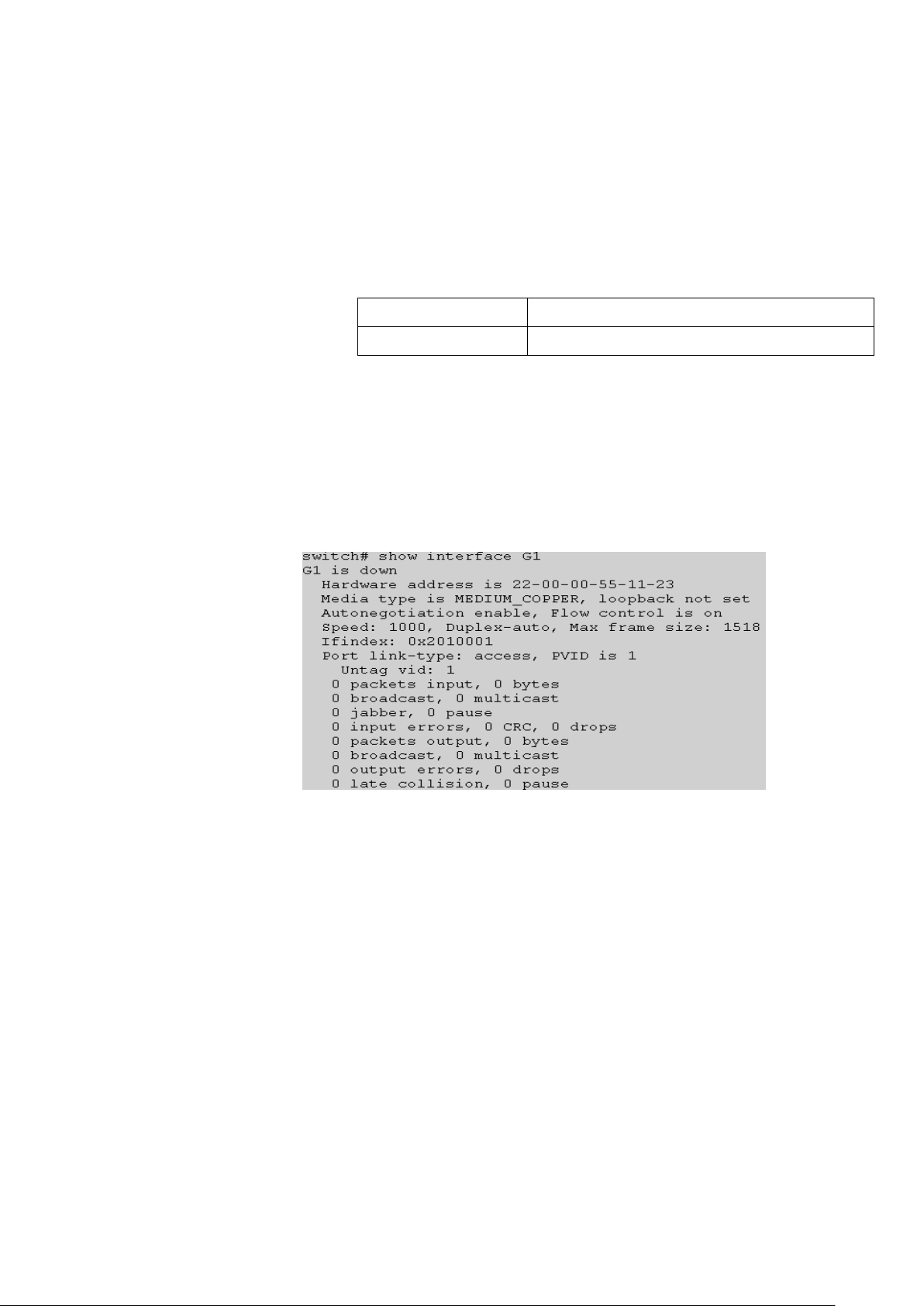
1.4.1 show interface
Command Description
This command is used to display the packet statistics of one or more
ports.
Parameter
Default
None
Command Mode
Privileged mode
Example
switch# show interface G1
1.5 LACP status
Function Brief
This function module is used to display the LACP port configurations.
1.5.1 lacp state
Command Description
This command is used to display the status of the LACP system.
Parameter
None
Default
None
Command Mode
Page 11

bgp
View the BGP routing information
connected
View the connected routing information
ospf
View the ospf routing information
rip
View the rip routing information
static
View the static routing information
A.B.C.D
View contains specific IP routing information
A.B.C.D/M
View of a routing information
summary
View all routing summary information
Global configuration mode
Example
switch(config)# lacp state
1.6 View route
Function Brief
The function module is used to display switch routing information.
1.6.1 show ip route
Command Description
This command is used to display the router information.
Parameter
Default
Command Mode
Example
switch# show ip route connected
None
Privileged mode
Page 12

1.7 ERPS-RING status
Function Brief
The function module is used to display erps information.
1.7.1 show erps
Command Description
This command is used to display the erps information.
Parameter
None
Default
None
Command Mode
Privileged mode
Example
switch# show erps
1.8 Power status
Function Brief
The function module is used to display power supply information.
1.8.1 show power
Command Description
This command is used to display the power supply information.
Parameter
None
Default
None
Command Mode
Privileged mode
Example
switch# show power
Page 13

2. System Setting Commands
2.1 IP config
IP address configuration commands include:
ip address
ip address dhcp
ip address old_ip A.B.C.D/M new_ip A.B.C.D/M
show ip interface
notice:A.B.C.D/M,Example:192.168.1.1/24
Function Brief
The IP configuration module is used to add, delete or display the
interface IP information of a switch.
2.1.1 ip address
Command Description
Configure IP port for A.B.C.D/M
no ip address A.B.C.D/M
//Delete ports IP A.B.C.D/M
Parameter
None
Default
VLAN 1 interface
Command Mode
VLAN interface configuration mode
Example
switch(config)# interface vlanif1
switch(config-vlanif1)#ip address 192.168.100.1/24
switch(config-vlanif1)#no ip address 192.168.100.1/24
2.1.2 ip address dhcp
Command Description
Configure IP port for automatic access (network DHCP server will
assign a dynamic IP) for the switch port.
no ip address dhcp
Page 14

//Disables the IP of the interface to access automatically.
Parameter
None
Default
Open port
Command Mode
Interface configuration mode
Example
switch(config)# interface vlanif1
switch(config-vlanif1)#ip address dhcp
switch(config-vlanif1)#no ip address dhcp
2.1.3 ip address old_ip
Command Description
ip address old_ip A.B.C.D/M new_ip A.B.C.D/M
Change the IP configuration of the interface (amend the old_ip to
new_ip)
Parameter
None
Default
None
Command Mode
Interface configuration mode
Example
switch(config)# interface vlanif1
switch(config-vlanif1)#ip address old_ip 192.168.255.1/24 new_ip
192.168.10.1/24
2.1.4 show interface
Command Description
This command is used to display the interface IP information.
Parameter
None
Default
Enabled port
Command Mode
Privileged mode and Global configuration mode
Page 15

guest
permissions for all users of the guest is limited to check the
system status information under the menu bar
admin
permissions for the admin user, you can add, modify, delete
all configuration
Example
switch(config)#show interface vlanif1
switch#show interface vlanif1
2.2 User config
User configuration commands include:
username name
show user
Note: name indicates the user name, which is a string of 1 to 32
characters. password indicates the password, which is a string of 1 -
32 characters.level indicates the user level, which ranges from 1
(lowest management rights) to 15 (highest management rights).
Function Brief
This function module is used to display, modify or add user
information so as to protect the switch configurations.
2.2.1 username name
Command Description
username name password passwd privilege level
//This command is used to add a user, modify the password of an existing
user, modify the management rights of an existing user, or modify the
password and management rights of an existing user.
no username name
//This command is used to delete a known user.
Parameter
Page 16

Default
admin
Command Mode
Global configuration mode
Example
switch(config)#username test password test
//Add a user "test", it is the default password is testing and rights: the
guest.
switch(config)#username test password test privilege admin
//Modify user: test, password: test, permissions: admin.
switch(config)#username test password test privilege guest
//Modify user: the test management authority for the guest.
switch(config)#no username test
//Delete user test.
2.2.2 show user
Command Description
This command is used to display all the current user configurations
of the switch.
Parameter
None
Default
None
Command Mode
Privileged mode
Example
Switch#show user
2.3 Time setting
The configuration commands include:
sntp enable|disable
sntp unicast-server
sntp auto-sync timer
sntp connect
sntp timezone
local-time date
Page 17

Function Brief
When enabled, this function can be used to automatically
synchronize the switch time with the network time.
2.3.1 sntp enable|disable
Command Description
ntp:
//This command is used to enable the NTP function.
no ntp:
//This command is used to disable the NTP function.
Parameter
None
Default
Disable
Command Mode
Global configuration mode
Example
switch(config)#sntp enable
switch(config)#sntp disable
2.3.2 sntp unicast-server
Command Description
sntp unicast-server A.B.C.D
//This command is used to add the IP address of an NTP server.
no sntp unicast-server A.B.C.D
//This command is used to delete the ip address of an NTP server.
Parameter
None
Default
None
Command Mode
Global configuration mode
Example
Switch(config)#sntp unicast-server 210.21.196.6
Page 18

<0-39>
Each number represents a time zone, can use SNTP
timezone show view the corresponding relationship
2.3.3 sntp auto-sync timer
Command Description
This command is used to set the SNTP synchronization time
interval.
Parameter
sntp auto-sync timer time,time Values range 5-65535s, 300s default
value.
Default
300s
Command Mode
Global configuration mode
Example
Switch(config)#sntp auto-sync timer 5
2.3.4 sntp connect
Command Description
sntp connect A.B.C.D
//This command is used to select the SNTP server to connect.
Parameter
None
Default
None
Command Mode
Global configuration mode
Example
switch(config)#sntp connect 210.21.196.6
2.3.5 sntp timezone set
Command Description
switch(config)# sntp timezone set<0-39>
//This command is used to select the time zone.
Parameter
Page 19

Default
0
Command Mode
Global configuration mode
Example
switch(config)#sntp timezone set 32
/ /Modify the time zone east eight area.
2.3.6 local-time date
Command Description
local-time date YYYY-MM-DD time HH:MM:SS
//Set the local time year - month - day hours: minutes: seconds
Parameter
None
Default
None
Command Mode
Global configuration mode
Example
switch(config)# local-time date 2015-3-18 time 12:12:12
// Note: due to the chip is limited, can only be set after January 1,1970.
Page 20

parameter
Parameters of the command mode
auto
Automatic negotiation.
full
Full duplex
half
Half duplex
3. Port configuration commands
3.1 Port config
Port configuration commands include:
duplex
speed
flow-control
shutdown
description
Function Brief
This module is used to configure basic parameters related to ports of
a switch. These basic parameters directly influence the port working mode.
3.1.1 duplex
Command Description
duplex {auto | full | half }
no duplex
//These commands are used to set the port rate mode.
Parameter
Default
By default, the duplex modes of all ports are Auto. For an optical port,
the duplex mode is always set to full.
Command Mode
Interface configuration mode
Note:
Light port duplex is fixed, is a full-duplex mode (full).
Example
// This command is used to modify the duplex mode of the G1 port.
switch(config)# interface G1
switch(config-G1)# duplex full
Page 21

parameter
Parameters of the command mode
10,100,1000,10000
The port rate is set to 10M, 100M and 1000M.
auto
The port rate is set to Auto.
3.1.2 speed
Command Description
speed {10 | 100 | 1000|10000|auto }
no speed
//It is used to set the port rate.
Parameter
Default
By default, the speed mode is set to auto for an electric port,
10000M for a f-port fiber port
Command Mode
Interface configuration mode
Note:
Port speed of light is coerced into 1000M and 10000M.
Electricity mouth can only set auto, 10M and 100M
Example
// The port rate of G1 is set to 100M.
switch(config)# interface G1
switch(config-G1)# speed 100
3.1.3 flow-control
Command Description
flowctrl
no flowctrl
//This command is used to enable or disable the flow control function of a
port.
Parameter
None
Default
The flow control function is enable by default
Command Mode
Interface configuration mode
Example
//enable the function.
switch(config-G1)# flowctrl
Page 22

3.1.4 shutdown
Command Description
shutdown
no shutdown
//This command is port switch.
Parameter
None
Default
The port is enabled by default.
Command Mode
Interface configuration mode
Example
//This command is used to disable a port.
switch(config)#interface G1
switch(config-G1)# shutdown
3.1.5 description
Command Description
This command is to configure the port description information,
convenient for management (composed of letters, Numbers and
underscore).
Parameter
None
Default
None
Command Mode
Interface configuration mode
Example
switch(config)#interface G1
switch(config-G1)# description A1_1
3.2 Rate limit
Function Brief
It is used to configure the speed limiting policy of a port to limit the
ingress and egress rates of all packets of the port.
Page 23

1-10000000
Port speed range is 1-10000000kbps
Parameter
Parameters of the command mode
3.2.1 rate-limit
Command Description
rate-limit {1-10000000 } egress/ingress
no rate-limit egress/ingress
//Configure port egress / ingress speed limit function, use the no form, port restore
default settings .
Parameter
Default
0
Command Mode
Interface configuration mode
Example
//The speed limit exports 10000 Kbps
switch(config)#interface G1
switch(config-G1)# rate-limit 10000 egress
3.3 Port mirroring
Function Brief
Port mirroring is also called port monitoring. Port monitoring is a data
packet acquisition technology. It can be configured on a switch to copy data
packets from one or more ports (mirror source ports) to a specified port
(mirror destination port). The destination port is connected to a host installed
with the packet analysis software. The software analyzes the collected
packets to implement network monitoring and eliminating network faults.
3.3.1 monitor
Command Description
monitor session <1-4> ingress destination <IFNAME> source
<IFNAME>
no monitor session <1-4>
//Configure port mirroring function, use the no form of the command, delete the
image settings.
Parameter
Page 24

1-4
Port mirror number
IFNAME
port number,Example G1,T1
Default
None
Command Mode
Global configuration mode
Example
//This command is to configure the session 1 source port for G1,G2, destination
port for G3.
switch(config)# monitor session 1 both destination G3 source G1
G2
3.4 Link aggregation
Static aggregation configuration commands include:
Trunk
Dynamic aggregation configuration commands include:
lacp enable | disable
lacp active | passive
lacp key
lacp port-priority
Function Brief
Link aggregation is used to form a logical port using multiple physical
ports of a switch. Multiple links within the same aggregation group are
deemed as a larger bandwidth logical link.
By link aggregation, the communication traffic is shared among
member ports of the aggregation group, and thus the bandwidth is increased.
Besides, member ports of the same aggregation share dynamic backups
with each other, and thus the link reliability is improved.
3.4.1 trunk
Member ports of the same aggregation group shall have the same
configurations. The configurations mainly include STP, QoS, VLAN, port
attribute, MAC address learning, ERPS configuration, loop protection
configuration, mirror, 802.1x, IP filtering, MAC filtering, port isolation, etc.
Command Description
Page 25

both-mac
Based on the source mesh MAC load balancing
dst-mac
Based on the destination MAC load balancing
src-mac
Based on the source MAC load balancing
interface trunk [trunk ID]
Configuration trunk
trunk [trunk ID]
Default
None
Command Mode
Global configuration mode
Example
switch(config)# interface trunk 1
switch(config)# interface G1
switch(config-G1)# trunk 1
3.4.2 load-balance
Command Description
load-balance
//This command is to set up static aggregation of load balance mode.
Parameter
Default
Disable
Command Mode
Interface configuration mode
Example
//This command is to set up load balancing model based on source and
destination MAC.
switch(config)# load-balance both-mac
3.4.3 lacp enable | disable
Command Description
lacp enable
//This command is used to enable dynamic aggregation of ports.
lacp disable
//This command is used to disable dynamic aggregation of ports.
Parameter
Page 26

None
Default
Disable
Command Mode
Interface configuration mode
Example
switch(config)#interface G1
switch(config-G1)# lacp disable
3.4.4 lacp active | passive
Command Description
lacp active
lacp passive
//This command is used to configure the role of an LACP port.
//It specifies the role of a port, which is active or passive.
Parameter
None
Default
active
Command Mode
Interface configuration mode
Example
switch(config)#interface G1
switch(config-G1)# lacp active
3.4.5 lacp key
Command Description
LACP key refers to the management key value of a dynamic
aggregation port and determines whether the port can be added into
an aggregation port. LACP protocol generates an operation key
based on the port configuration (that is, the rate, duplex, basic
configuration and management key). Members of a dynamic
aggregation group can only be aggregated when they have the
same operation key.
Parameter
<1-65535>: The key value is manually specified. The value ranges
from 1 to 65535.
Page 27

auto: The key value is automatically negotiated.
Default
auto
Command Mode
Interface configuration mode
Example
switch(config)# interface G1
switch(config-G1)# lacp key 100
3.4.6 lacp port-priority
Command Description
lacp port-priority <1-32768>
//This command is used to configure the priority of an LACP port.
Parameter
<1-32768>: It specifies the priority range. A smaller value indicates a
higher priority.
Default
0
Command Mode
Interface configuration mode
Example
switch(config)# interface G1
switch(config-G1)# lacp port-priority 100
3.4.7 example
The link aggregation is used to increase the bandwidth of device-level serial
ports and share loads based on the source/destination MAC address.
SW1/SW2:
switch# configure terminal
Page 28

switch(config)# load-balance both-mac
switch(config)# interface trunk 1
switch(config)# interface G1
switch(config-G1)# trunk 1
switch(config)# interface trunk 1
switch(config)# interface G2
switch(config-G1)# trunk 1
phenomenon:
After aggregation, two links form one logical link and thus the
bandwidth is doubled. Besides, the load is shared based on the source or
destination MAC address. When one link in the aggregation group is
disconnected, the packet is sent through another link, and thus the
communication is not interrupted.
Page 29

4. Advanced configuration commands
4.1 VLAN config
VLAN configuration commands include:
switchport mode
switchport pvid
switchport trunk|hybrid| access
show vlan
Function Brief
Ethernet is a shared communication media based on the Carrier
Sense Multiple Access/Collision Detect (CSMA/CD) technology. A LAN built
using the Ethernet technology is not only a collision domain, but also a
broadcast domain. When the number of hosts on the network is large, the
collision becomes serious, broadcast flooding occurs, and the performance
is significantly degraded. Even worse, the network is unavailable.
Deployment of bridges or L2 switches on the Ethernet can resolve the
problem of serous collision, but still cannot isolate broadcast packets. To
address this issue, the Virtual Local Area Network (VLAN) technology
emerges. This technology can divide a physical LAN into multiple logical
LANs, that is, VLANs. Hosts located in the same VLAN can directly
communicate with each other, but hosts located in different VLANs cannot
communicate with each other. In this way, broadcast packets are confined in
the same VLAN. That is, each VLAN is a broadcast domain.
Advantages of VLAN are as follows:
1) Improve network performance. Broadcast packets are confined in the
VLAN, which effectively controls broadcast storms of the network, saves the
network bandwidth, and improves the network processing capability.
2) Enhance network security. Devices in different VLANs cannot access
each other, and hosts in different VLANs cannot directly communicate with
each other. Packets must be forwarded at L3 through network layer devices,
such as routers or L3 switches.
3) Simplify network management. Hosts in the same virtual work group are
not limited to a certain physical range, which simplifies network management,
and makes it convenient for people in different areas to set up work groups.
Page 30

Parameter
Parameters of the command mode
access
Access mode
trunk
Trunk mode
Hybrid
Hybrid mode
Parameter
Parameters of the command mode
Vlan-id
Vlan id.Value range:1-4094.
4.1.1 switchport mode
Command Description
switchport mode {access | trunk | hybrid }
//This command is to configure the port mode.
Parameter
Default
Access mode
Command Mode
Interface configuration mode
A switch port supports the following modes:
Access mode: The port belongs to only one VLAN, and only
sends and receives untagged Ethernet frames.
Trunk mode: The port is connected with other switches, and can
receive and send tagged Ethernet frames.
Hybrid mode: The port can be connected to a PC or a switch and
router. (The hybrid mode is the combination of the access mode
and the trunk mode.)
Example
//The port is configured to VLAN trunk /hybrid/access.
Switch(config)# interface T1
Switch(config-T1)#switchport mode trunk /hybrid/access
4.1.2 switchport pvid
Command Description
switchport pvid { vlan-id}
Parameter
Default
Vlan1
Command Mode
Interface configuration mode
Page 31

Parameter
Parameters of the command mode.
Vlan-id
Vlan id,Value range:1-4094.
Parameter
Parameters of the command mode
vlan-id
The display VLAN Value range:1-4094.
Example
//The default vlan Settings for the port for vlan2.
Switch(config)# interface T1
Switch(config-T1)# switchport pvid 2
4.1.3 switchport trunk|hybrid| access
Command Description
switchport trunk tag {vlan-id}
switchport hybrid tag|untag|unpvid {vlan-id}
switchport access {vlan-id}
Parameter
Default
All ports are members of vlan1, do not belong to other vlan
Command Mode
Interface configuration mode
Example
//This command is the trunk mode port to join one vlan or multiple vlan.
switch(config)# interface T1
switch(config-T1)# switchport mode trunk
switch(config-T1)# switchport trunk tag 2
switch(config-T1)# switchport trunk tag 3-4
//This command is the hybrid mode port to join one vlan or multiple vlan.
switch(config-T1)# switchport mode hybrid
switch(config-T1)# switchport hybrid tag|untag 2
switch(config-T1)# switchport hybrid tag| untag 3-4
//This command is to access mode port to join vlan2
switch(config-T1)# switchport access 2
4.1.4 show vlan
Command Description
show vlan [vlan-id ]
Parameter
Default
Page 32
None
Command Mode
Privileged mode
Example
//This command is to display all VLAN information.
Switch#show vlan
Vid Status Name Ports
---------------------------------------------------------------
------------------------------------
1 static vlan1 G1 G2 G3 G4 T1 T2 T3 T4 T5 T6 T7 T8 T9
T10 T11 T12 T13 T14 T15 T16 T17 T18 T19
T20 T21 T22 T23 T24
2 static vlan2
3 static vlan3
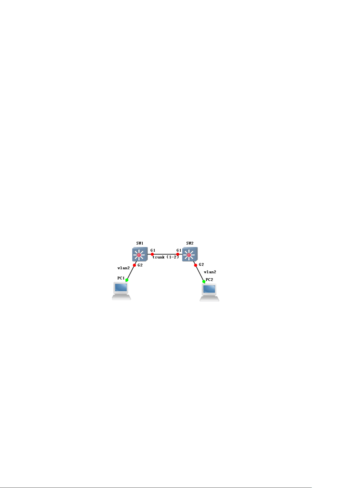
4.1.5 example
Enable VLAN communication across different switches. (PC1 and PC2 can
communicate with each other normally.)
SW1/SW2:
switch# configure terminal
switch(config)# interface G1
switch(config-if)# switchport mode trunk
switch(config-if)# switchport trunk tag 2
switch(config-if)# exit
switch(config)# interface G2
switch(config-if)# switchport mode access
switch(config-if)# switchport access vlan 2
phenomenon:
pc1(192.168.222.107)and pc2(192.168.222.94)are mutually
pinged.
Page 33

4.2 QinQ config
Qinq configuration commands include:
Qinq
Qinq otpid
Function Brief
QinQ technology through the stacked two 802.1Q in the Ethernet
frame header, effectively expanded the number of VLAN, make the
number of vlans up to 4094x4094.
4.2.1 qinq
Command Description
Enable qinq
//no qinq express disable qinq function.
Parameter
None
Default
None
Command Mode
Interface configuration mode
Example
switch(config)# interface G1
switch(config-G1)# qinq
4.2.2 qinq otpid
Command Description
Configuration tag QinQ layer protocol type.
Parameter
Page 34

<0x0000-0x9999>
Tag QinQ layer protocol type
Parameter
Parameters of the command mode
time
The value range is <0,
10-1000000>.
Default
0x8100
Command Mode
Interface configuration mode
Example
switch(config)# qinq otpid 0x88a8
4.3 MAC config
MAC configuration commands include:
mac-address aging-time
show mac-addres
Function Brief
The switch is able to send packets directly to the destination node instead of
sending packets to all nodes as a hub,the key technology is that the switch can
identify the network card MAC address of the node, then put them in a place called
MAC address table. The MAC address table is stored in the switch's cache and
remembers these addresses.In this way, when the data is sent to the destination
address, the switch can locate the node position of the MAC address in the MAC
address table, and then send the data directly to the node of the location. MAC
address number refers to the number of MAC addresses that can be stored in the
MAC address table of the switch, the more the number of MAC addresses is stored,
the higher the speed and efficiency of data forwarding.
4.3.1 mac-address aging-time
Command Description
mac address-table aging-time time {10-1000000}:
//This command is used to set the aging time of the MAC address. If the aging time
is set to 0, the MAC address is automatically aged.
no mac address-table aging time:
//This command is used to restore the default aging time.
Parameter
Default
Page 35

None
Command Mode
Global configuration mode
Example
//Set the MAC address aging time to 100s.
switch(config)# mac-address aging-time 100
//Set the MAC address aging time to 300s.
switch(config)# no mac-address aging-time
4.3.2 show mac-address
Command Description
show mac-addres{ aging-time}
Parameter
None
Default
None
Command Mode
Global configuration mode
Example
//This command can display the MAC address and MAC address of the aging time.
switch# show mac-address
MAC Vlan Port Type
------------------------------------------------------------------------------------
94-de-80-dc-cf-38 1 G4 dynamic
60-92-17-9d-30-c3 1 G4 dynamic
Switch# show mac-address aging-time
Mac address aging-time : 100
4.4 ARP config
ARP configuration commands include:
show arp
arp static
arp timeout
Function Brief
This function module, you can view the ARP entry information that the switch
has learned, you can add ARP static entries to prevent unauthorized access to the
Page 36

Parameter
Parameters of the command mode
ip_addr
Ip address,Value range:X.X.X.X.
mac_addr
Mac address,Value range:H.H.H.H
host and modify the aging time of ARP entries.
4.4.1 show arp
Command Description
show arp
//This command to display the ARP.
Parameter
None
Default
None
Command Mode
Global configuration mode
Example
//This command to display the ARP.
switch(config)# show arp
4.4.2 arp static
Command Description
arp static ip_addr mac_addr
//This command is used to add a static entry.
no arp static ip_addr
//This command is used to delete a static entry.
Parameter
Default
None
Command Mode
Global configuration mode
Example
// Add a static entry.
switch(config)# arp static 192.168.111.1 00-00-a1-b2-c3-d4
4.4.3 arp timeout
Command Description
Page 37

Parameter
Parameters of the command mode
seconds
Unit :second, value range:60-86400.
arp timeout seconds
//This command is used to set the aging time.
no arp timeout
//This command is used to cancel time Settings.
Parameter
Default
None
Command Mode
Interface configuration mode
Example
//This command is to set up the ARP aging time for 3000 seconds.
switch(config)# interface vlanif1
switch(config-vlanif1)# arp timeout 3000
4.5 MSTP config
MSTP configuration commands include:
spanning-tree
spanning-tree mode
spanning-tree max-age
spanning-tree hello-time
spanning-tree forward-delay
spanning-tree max-hop
spanning-tree instance
show spanning-tree
show spanning-tree interface brief
Function Brief
STP is developed based on IEEE 802.1D, and is a protocol used to
eliminate physical loops at the data link layer in the LAN. STP-enabled
devices exchange information to detect loops on the network, and
selectively block some ports to change a loop topology into a loop-free tree
topology. This prevents continuous growing and infinite loop of packets on
the loop network, and prevents occurrence of problems such as degraded
packet processing capability of devices caused by repeated receiving of the
Page 38

Stp
Enable STP
rstp
Enable RSTP
mstp
Enable MSTP
same packets.
Protocol packets used by STP are Bridge Protocol Data Units
(BPDUs), which are also called configuration messages. A BPDU contains
sufficient information to ensure that a device can complete the spanning tree
computation process. STP transfers BPDUs between devices to determine
the network topology.
4.5.1 spanning-tree
Command Description
spanning-tree:
//This command is used to enable the STP function.
no spanning-tree:
//This command is used to disable the STP function.
Parameter
None
Default
Enable
Command Mode
Global configuration mode
Example
switch(config)# spanning-tree
switch(config)# no spanning-tree
4.5.2 spanning-tree mode
Command Description
spanning-tree mode {stp|rstp|mstp}
//This command is used to set the STP version.
Parameter
Default
stp
Command Mode
Page 39

seconds
BPDU biggest survival time.Value range:6-40s.
Time
Hello message sending interval,Value range:1-10s.
Global configuration mode
Example
switch(config)# spanning-tree mode rstp
//Set the STP version to RSTP.
4.5.3 spanning-tree max-age
Command Description
spanning-tree max-age {6-40}
Parameter
Default
20s
Command Mode
Global configuration mode
Example
//This command configure the STP the largest survival time for 24 seconds.
switch(config)# spanning-tree max-age 24
4.5.4 spanning-tree hello-time
Command Description
spanning-tree hello-time{1-10}
Parameter
Default
2s
Command Mode
Global configuration mode
Example
Switch(config)# spanning-tree hello-time 10
//This command configure the STP hello message sending time interval to 10 seconds.
4.5.5 spanning-tree forward-delay
Command Description
spanning-tree forward-delay{4-30}
Page 40

time
Forwarding delay ,Value range:4-30s.
hop
BPDU max-hop, Value range:1-40.
Parameter
Default
15 seconds
Command Mode
Global configuration mode
Example
switch(config)# spanning-tree forward-delay 20
//This command configure the STP forwarding delay for 20 seconds.
4.5.6 spanning-tree max-hop
Command Description
spanning-tree max-hop{1-40}
Parameter
Default
20
Command Mode
Global configuration mode
Example
switch(config)# spanning-tree max-hop 40
//This command configure bpdus protocol packet maximum hop count of 40
effective.
4.5.7 spanning-tree instance
Command Description
spanning-tree instance
//This command is to configure the vlan and examples of MSTP mapping relationship.
Parameter
None
Default
None
Command Mode
Global configuration mode
Example
Page 41

switch(config)# spanning-tree instance 44 vid 4
4.5.8 spanning-tree mstp name
Command Description
spanning-tree mstp name
//This command is to configure the MSTP domain name.
Parameter
None
Default
None
Command Mode
Global configuration mode
Example
switch(config)# spanning-tree mstp name 2
4.5.9 spanning-tree mstp revision
Command Description
spanning-tree mstp revision
//This command is the configuration revision number of MSTP.
Parameter
None
Default
None
Command Mode
Global configuration mode
Example
switch(config)# spanning-tree mstp revision 2
4.5.10 show spanning-tree
Command Description
show spanning-tree
Parameter
None
Default
None
Page 42

Command Mode
Global configuration mode and Privileged mode
Example
//Display the STP configuration.
switch# show spanning-tree
Spanning-tree is disable:
max age 20 bridge forward delay 20
forward delay 15 max hops 20
hello time 2 orce protocol version mstp
4.5.11 show spanning-tree interface brief
Command Description
show spanning-tree interface brief
Parameter
None
Default
None
Command Mode
Global configuration mode and Privileged mode
Example
switch(config)# show spanning-tree interface brief
4.6 IGMP-snooping
IGMP snooping configuration commands include:
igmp-snooping
igmp-snooping host-age-time
igmp-snooping fast-leave
igmp-snooping static-group
Page 43

Parameter
Parameters of the command mode
time
Old Time,value range:200-1000s.
show igmp-snooping group
Function Brief
Internet Group Management Protocol Snooping, shorted as IGMP
Snooping, is a multicast restriction mechanism running on a L2 device to
manage and control multicast groups. The L2 device on which IGMP
Snooping runs analyzes the received IGMP packets, create a mapping
relationship between ports and MAC multicast addresses and forwards
multicast data according to the mapping relationship
4.6.1 igmp-snooping
Command Description
ip igmp snooping:
//This command is used to enable the igmp-snooping function.
no ip igmp snooping:
//This command is used to disable the igmp-snooping function.
Parameter
None
Default
Disable
Command Mode
Global configuration mode
Example
//This command will configure open and closed igmp snooping:
switch(config)# igmp-snooping
switch(config)#no igmp-snooping
4.6.2 igmp-snooping host-age-time
Command Description
igmp-snooping host-age-time{200-1000}
Parameter
Default
260S
Command Mode
Global configuration mode
Page 44

Example
//This command will configure a old time of 200s:
switch(config)# igmp-snooping host-age-time 200
4.6.3 igmp-snooping fast-leave
Command Description
ip igmp-snooping fast-leave:
//This command is used to enable the immediate leave function of a port.
no ip igmp-snooping fast-leave:
//This command is used to disable the immediate leave function of a port.
Parameter
None
Default
Disable
Command Mode
Interface configuration mode
Example
switch(config)# interface G1
switch(config-G1)# igmp-snooping fast-leave
4.6.4 igmp-snooping static-group
Command Description
igmp-snooping static-group
//This command is to add the static multicast group.
no igmp-snooping static-group
//This command is to delete the static multicast group.
Parameter
None
Default
Disable
Command Mode
Interface configuration mode
Example
switch(config)# interface G1
switch(config-G1)# igmp-snooping static-group 224.1.1.1 vlan 2
switch(config-G1)# no igmp-snooping static-group 224.1.1.1 vlan 2
Page 45

4.6.5 show igmp-snooping group
Command Description
show igmp-snooping group
Parameter
None
Default
None
Command Mode
Privileged mode
Example
//This command is to display multicast group information:
switch# show igmp-snooping group
VID SOURCE GROUP interFACE
----------------------------------------------- ----------------------1 0.0.0.0 233.45.18.88 G4
1 0.0.0.0 239.255.255.250 G4 G2
1 0.0.0.0 224.0.0.252 G2 G4
4.6.6 example
Member ports requesting to join the multicast group can receive multicast
streams, but non-member ports not requesting to join the multicast group cannot
receive multicast streams.
switch# configure terminal
switch(config)# igmp snooping
switch(config)# interface G1
switch(config-G1)# igmp-snooping static-group 233.2.2.2 vlan 1
switch(config)# interface G2
switch(config-G2)# igmp-snooping static-group 233.2.2.2 vlan 1
switch(config)# interface G3
Page 46

switch(config-G3)# igmp-snooping static-group 233.2.2.2 vlan 1
phenomenon:
PC2/PC3 can receive video streams from the multicast source, but PC4
cannot.
4.7 DHCP server
DHCP server configuration commands include:
ip dhcpd
dhcp pool
network
default-router
dns-server
static
lease
domain-name
netbios-name-server
Function Brief
DHCP server refers to a computer that manages DHCP standards on a
specific network. It allocates a unique IP address to each workstation that logs in to
the server. DHCP server greatly simplifies network management which needs to be
manually completed before.
4.7.1 ip dhcpd
Command Description
ip dhcpd enable:
//This command is used to enable the DHCP service.
ip dhcpd disable:
//This command is used to disable the DHCP service.
Parameter
None
Default
Disable
Command Mode
Global configuration mode
Example
Page 47

Parameter
Parameters of the command mode
NAME
Pool name ,Example:dizhichi
Parameter
Parameters of the command mode
A.B.C.D/M
Address
pool,Example:192.168.1.0/24
vlanif-id
Interface Vlan id
//This command is used to globally enable the DHCP server.
switch(config)# ip dhcpd enable
4.7.2 dhcp pool
Command Description
dhcp pool <word>:
// This command is used to add a DHCP address pool.
No dhcp pool <word>:
// This command is used to delete a DHCP address pool with the specified name.
Parameter
Default
None
Command Mode
Global configuration mode
Example
//This command is to create a named dizhichi address pool.
switch(config)#dhcp pool dizhichi
4.7.3 network
Command Description
network A.B.C.D/M vlanif-id
//This command is used to add an IP address segment to the address pool.
Parameter
Default
None
Command Mode
Address pool configuration mode
Example
Page 48

Parameter
Parameters of the command mode
A.B.C.D
Default-router
Parameter
Parameters of the command mode
A.B.C.D
dns address
switch(config-dhcp)#Network 192.168.1.0/24 vlanif1
//Set the DHCP from vlan1 distributed address segment is 192.168.1.0/24
4.7.4 default-router
Command Description
Default-router <A.B.C.D>:
//This command is used to configure the default gateway of the address pool.
Parameter
Default
None
Command Mode
Address pool configuration mode
Example
switch(config-dhcp)#Default-router 192.168.1.1
//This command is to set up DHCP issued a gateway.
4.7.5 dns-server
Command Description
Dns-server<A.B.C.D>:
// This command is used to configure the IP address of the DNS server.
Parameter
Default
None
Command Mode
Address pool configuration mode
Example
switch(config-dhcp)#dns-server 192.168.1.1
//Set the DNS server address 192.168.1.1
4.7.6 static
Command Description
Page 49

Paramet
er
Parameters of the command mode
A.B.C.D
Static binding IP
MAC
Static binding MAC
Parameter
Parameters of the command mode
<0-31536000>
Time range Unit: second
infinite
permanent
static A.B.C.D MAC
//This command is used to static binding IP and MAC.
no static A.B.C.D
//This command is used to delete static binding.
Parameter
Default
None
Command Mode
Address pool configuration mode
Example
switch(config-dhcp)#static 192.168.1.1 11-11-11-11-11-11
//This command is static binding 192.168.1.1 and 11-11-11-11-11-11
switch(config-dhcp)#no static 192.168.1.1
//This command is used to delete static binding.
4.7.7 lease
Command Description
lease <0-31536000>/infinite
//This command is used to configure the lease period of the IP address in the
address pool.
Parameter
Default
Infinite
Command Mode
Address pool configuration mode
Example
// This command is used to configure the lease time of the address pool to 3600s.
switch(config)# dhcp pool 1
switch(config-dhcp)# lease 3600
Page 50

Parameter
Parameters of the command mode
domain
Domain-name,Example:www.dahua.com
Parameter
Parameters of the command mode
A.B.C.D
DNS ip address
4.7.8 domain-name
Command Description
domain-name domain
//This command is used to configure the DNS server domain name.
Parameter
Default
None
Command Mode
Address pool configuration mode
Example
switch(config)# dhcp pool 1
switch(config-dhcp)# domain-name www.dahua.com
//This command is used to configure the DNS server domain name at
www.dahua.com.
4.7.9 nbns-server
Command Description
nbns-server A.B.C.B
//This command is used to configure the secondary DNS server.
Parameter.
Default
None
Command Mode
Address pool configuration mode
Example
//Set the secondary DNS server address 114.114.114.114 .
switch(config)# dhcp pool 1
switch(config-dhcp)# nbns-server 114.114.114.114
4.7.10 example
that IP addresses at the client are uniformly allocated by the server.
This command is used to configure the switch to a DHCP server, so
Page 51

switch# configure terminal
switch(config)# ip dhcpd enable
switch(config)# dhcp pool a
switch(config-dhcp)# default-router 192.168.1.1
switch(config-dhcp)#dns-server 8.8.8.8
switch(config-dhcp)# lease 1000
switch(config-dhcp)# network 192.168.1.0/24 vlanif1
phenomenon:
Clients including PC1-PC100 can obtain correct IP addresses from
the DHCP server (SW 1).
Note: An L3 interface of the same VLAN shall be configured for the
DHCP server in the VLAN, so that the DHCP server can distribute IP
addresses to clients in the VLAN.
4.8 DHCP relay
Function Brief
If the DHCP client and the DHCP server on the same physical
network segment, the client can correctly obtain the IP address of dynamic
allocation. If they are not in the same physical network, they need DHCP
Relay Agent (relay agent). DHCP Relay agent can be removed to the
necessary of DHCP server should be in each physical segment, It can
deliver messages to the DHCP server that is not in the same physical
subnet,it can also send a message back to the DHCP client that is not in the
same physical subnet.
4.8.1 ip helper-address
Command Description
ip helper-address A.B.C.D
//This command is used to enable the DHCP relay.
Page 52

no ip helper-address A.B.C.D
//This command is used to disable the DHCP relay.
Parameter
None
Default
Disable
Command Mode
Interface configuration mode
Example
//This command is used to open the DHCP relay in vlan 1
switch(config)#interface vlanif1
switch(config-vlanif1)# ip helper-address 192.168.1.1
4.9 DHCP snooping
DHCP snooping configuration commands include:
ip dhcp-snooping
ip dhcp-snooping trust
show ip dhcp-snooping lease
Function Brief
DHCP snooping is a security feature of DHCP, and provides the
following functions: Ensure that a client obtains its IP address from an
authorized server. If an unauthorized DHCP server that is built privately
exists on the network, the DHCP clients may obtain incorrect IP addresses
and network configuration parameters, and consequently cannot implement
communication normally. To ensure that DHCP clients can obtain IP
addresses from an authorized DHCP server, the DHCP snooping security
mechanism supports configuration of ports as trusted or untrusted ports.
1、A trusted port can forward received DHCP packets normally.
2、On receiving the DHCP-ACK and DHCP-OFFER packets from the
DHCP server, an untrusted port drops the packets.
4.9.1 ip dhcp-snooping
Command Description
ip dhcp-snooping:
//This command is used to enable the DHCP snooping configuration mode.
no ip dhcp-snooping:
Page 53

//This command is used to disable the DHCP snooping configuration mode.
Parameter
None
Default
Disable
Command Mode
Global configuration mode
Example
None
4.9.2 ip dhcp-snooping trust
Command Description
ip dhcp-snooping trust:
//This command is used to configure the DHCP snooping trust mode.
no ip dhcp-snooping trust:
//This command is used to configure the DHCP snooping non-trust mode.
Parameter
None
Default
Non-Trust
Command Mode
Interface configuration mode
Example
//This command is to set port 1 model for trust.
switch(config)#interface G1
switch(config-G1)# ip dhcp-snooping trust
4.9.3 show ip dhcp-snooping lease
Command Description
show ip dhcp-snooping interface:
//This command is used to display the DHCP snooping trust mode of a port.
Parameter
None
Default
None
Command Mode
Page 54

Privileged mode
Example
switch# show ip dhcp-snooping lease
4.10 QoS config
QoS configuration commands include:
remark
cos default
trust
cos map
dscp map
scheduler police
Function Brief
QoS(Quality of Service) refers to a network can use a variety of basic
technology and provid better service capabilities for designated network
communications. It is a technique that used to solve the problem of network delay
and congestion.When the network overload or congestion, QoS can ensure that the
important traffic is not delayed or discarded,while ensuring the efficient operation of
the network.
4.10.1 remask
Command Description
Qos remask<all/cos/dscp>
Change the QoS trust mode weight.
Parameter
None
Default
Cos
Command Mode
Interface configuration mode
Example
//This command is to modify the G1 qos trust mode to DSCP port.
Page 55

switch(config)# interface G1
switch(config-G1)# qos remask dscp
4.10.2 cos default
Command Description
cos default<0-7>
Parameter
None
Default
0
Command Mode
Interface configuration mode
Example
//This command is to modify the G1 qos trust mode to COS port.
switch(config)# interface G1
switch(config-G1)# cos default 6
4.10.3 trust
Command Description
qos trust
//This command is to set port trust packets take priority.
no qos trust
//This command is to set port trust default port priority.
Parameter
None
Default
Qos trust
Command Mode
Interface configuration mode
Example
//This command is to set port 1 trust port the default priority.
Switch(config)#interface G1
switch(config-G1)# no qos trust
Page 56

Dscp priority
Cos priority
0-7 0 8-15
1
16-23
2
24-31
3
32-39
4
40-47
5
48-55
6
56-63
7
4.10.4 cos map
Command Description
cos map
Set the mapping relationship between COS priority and queue.
Parameter
None
Default
Priority and queue one-to-one mapping
Command Mode
Global configuration mode
Example
//Map the cos priority 0 to the queue 3
switch(config)# cos map 0 3
4.10.5 dscp map
Command Description
dscp map
//Mapping relationship between DSCP priority and COS priority.
Parameter
None
Default
Command Mode
Global configuration mode
Example
//Map the DSCP priority 45 to Cos priority 7
switch(config)# cos map 45 7
Page 57

sp
Strict priority mode: First in the queue with the highest priority
service, until the priority is empty and service for the next high
priority queue, and so on.
wrr
Weighted round robin scheduling algorithm: To support different
bandwidth requirements, it can allocate different proportion of
output bandwidth for different queues.
4.10.6 scheduler policy
Command Description
scheduler police
//Set Qos scheduling algorithm.
Parameter
Default
sp
Command Mode
Global configuration mode
Example
switch(config)# scheduler policy wrr 1 2 3 4 5 6 7 8
4.10.7 example
Test topology map (test is based on the QoS of ports)
The 1-3 port of the Ixia tester corresponds to the G18-G22 of the switch.
(一)Configuration
// When the data packets in the port is not marked with any priority, the priority of
the port is set to the corresponding queue.
a、Set the packets which enter the 18 port are marked with priority 7 and set
the packets which enter the 20 port are marked with priority 6.
switch(config)#interface G18
switch(config-G18)cos default 7
switch(config-G18)no qos trust
switch(config-G18)exit
Page 58
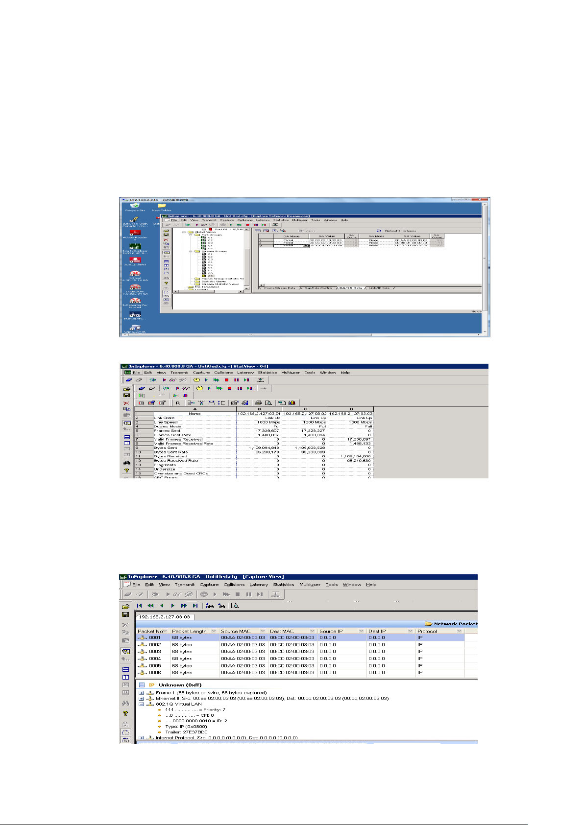
switch(config)#interface G20
switch(config-G20)cos default 6
switch(config-G20)no qos trust
b、Set the destination address of the Ixia1-2 port to the source MAC address
of the Ixia3 port.
c、1-2 ports start sending data packets after learning MAC addresss.
(二)Test result
Conclusion:pass
Observe the source MAC address of the packets which capture in port
3 ,you can find that the received data packets from port 11.
the packets of high queue first pass
Page 59

Parameter
Parameters of the command mode
Group
VRRP group,1-255
Time
Time interval between1-10s,default 1s
4.11 VRRP
configuration commands include:
vrrp advertisement
vrrp IP
vrrp preempt
vrrp preempt time
vrrp priority
Function Brief
Virtual Router Redundancy Protocol,or VRRPfor short, it is proposed
by IETF to solve the routing protocol of single point of failure in the local area
network configuration.It has introduced a standard RFC2338 protocol in
1998. VRRP is widely used in the edge network, It is design intent to support
the IP data traffic failed to transfer in a given case will not cause confusion,
allow the host to use a single router, make the connectivity between routers
is still maintained timely in the case of the failure of the first hop router.
VRRP is a routing fault tolerance protocol, which can also be called
backup routing protocol. A default route is set for all hosts in a local area
network, when the destination address in the network from the host are not
in the network segment, the message will be sent to the external router
through the default route, so that the communication between the host and
the external network is realized. The internal host will not be able to
communicate with the external after the default router down off (port is
closed), If the router set up VRRP, then the virtual router will enable the
backup router at this time,so can achieve the whole network communication.
4.11.1 vrrp advertisement
Command Description
vrrp <group> advertisement <time>
Parameter
Default
Page 60

None
Command Mode
Interface configuration mode
Example
//Modify notification time of group1 is 5 seconds.
switch(config)# interface vlanif1
switch(config-vlanif1)# vrrp 1 advertisement 5
4.11.2 vrrp ip
Command Description
vrrp<group> ip A.B.C.D
//This command is to set up virtual routing IP address.
Parameter
None
Default
None
Command Mode
Interface configuration mode
Example
//This command is to set up virtual IP as 192.168.1.254.
switch(config)#interface vlanif1
switch(config-vlanif1)# vrrp 1 ip 192.168.1.254
4.11.3 vrrp preempt
Command Description
vrrp<group> preempt
//This command is VRRP preemption mode.
no vrrp<group> preempt
//This command is disabled VRRP preemption mode.
Parameter
None
Default
Enable
Command Mode
Interface configuration mode
Example
//This command is disabled VRRP preemption mode.
Page 61

switch(config)#interface vlanif1
switch(config-vlanif1)#no vrrp 1 preempt
4.11.4 vrrp preempt time
Command Description
vrrp<group> preempt time< 0-1000s>
//This command is to set the current VRRP group delay.
Parameter
Time: Time range 0-1000s,Default 0s
Default
0
Command Mode
Interface configuration mode
Example
//This command is to set up 3 seconds after the preemption.
switch(config)#interface vlanif1
switch(config-vlanif1)# vrrp 1 preempt 3
4.11.5 vrrp priority
Command Description
vrrp<group> priority <priority>
//This command is to set up the gateway priority.
Parameter
priority:Priority range1-254,Default 100,
the greater the number, the higher the priority.
Default
Enable
Command Mode
Interface configuration mode
Example
//This command is to set priorities for 111.
switch(config)#interface vlan1
switch(config-vlanif1)# vrrp 1 ip 192.168.2.1
switch(config-vlanif1)#vrrp 1 priority 111
Page 62
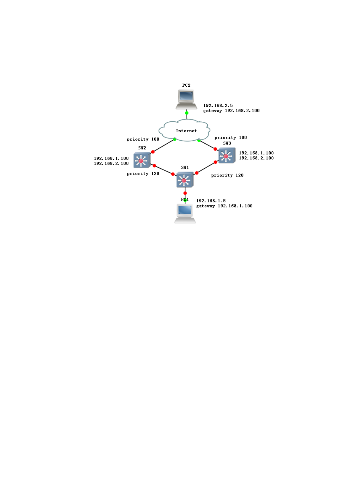
4.11.6 example
a, Network diagram as shown in Figure:
Sw1:
switch(config)# interface vlan1
switch(config-vlanif2)# ip address 192.168.1.11/24
switch(config-vlanif2)#exit
switch(config)# interface vlan2
switch(config-vlanif2)# ip address 192.168.2.11/24
switch(config-vlanif2)#exit
switch(config)# interface g2
switch(config-G2)# switchport mode access
switch(config-G2)# switchport pvid 2
switch(config)# interface vlanif1
switch(config-vlanif1)# vrrp 1 ip 192.168.1.100
switch(config-vlanif1)#vrrp 1 priority 120
switch(config)# interface vlanif2
switch(config-vlanif2)# vrrp 2 ip 192.168.2.100
switch(config-vlanif1)#vrrp 2 priority 120
Sw2:
switch(config)# interface vlan1
switch(config-vlanif2)# ip address 192.168.1.22/24
switch(config-vlanif2)#exit
Page 63
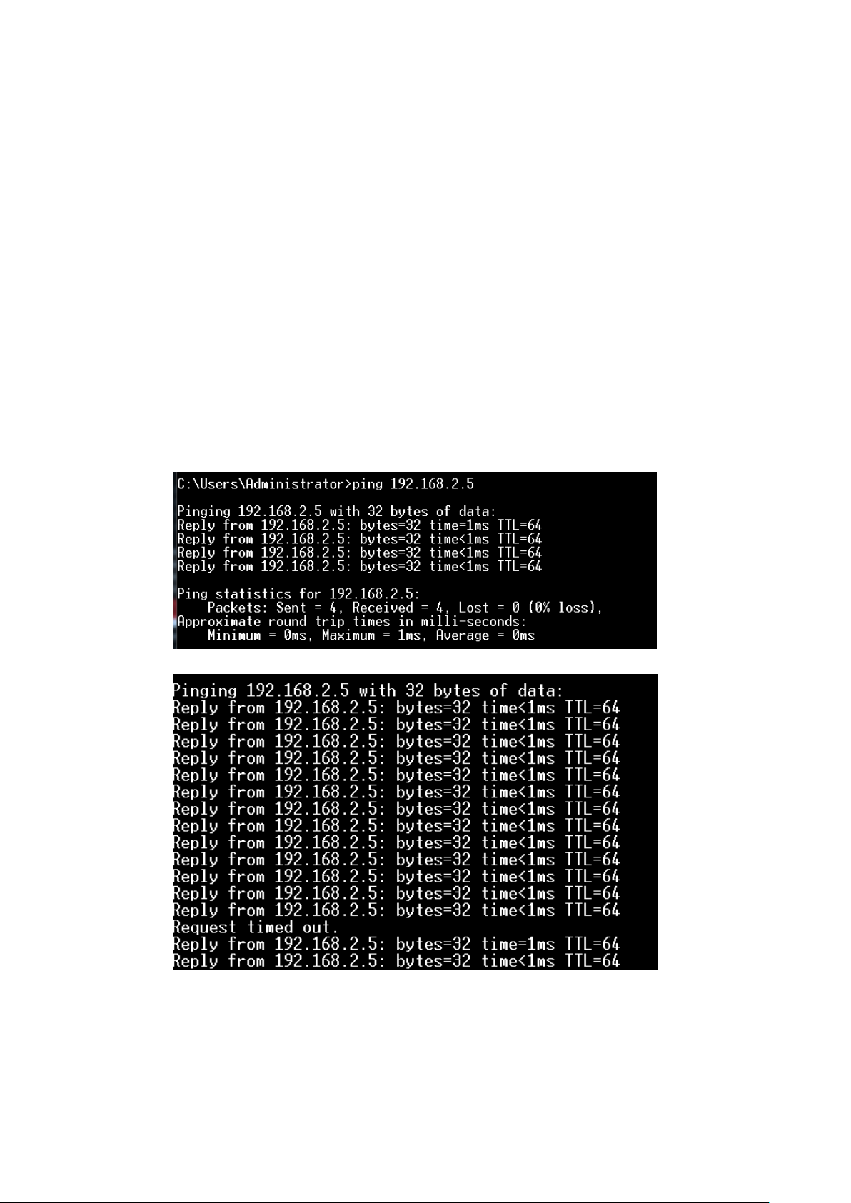
switch(config)# interface vlan2
switch(config-vlanif2)# ip address 192.168.2.22/24
switch(config-vlanif2)#exit
switch(config)# interface g2
switch(config-G2)# switchport mode access
switch(config-G2)# switchport pvid 2
switch(config)# interface vlanif1
switch(config-vlanif1)# vrrp 1 ip 192.168.1.100
switch(config)# interface vlanif2
switch(config-vlanif2)# vrrp 2 ip 192.168.2.100
Phenomena:
b, PC1 continued to ping PC2(you can capture data packets and find that the
packets forwarded by SW2)
c, Power down the SW2, observe the results of the Ping (switching time is about 3S)
Page 64

Parameter
Parameters of the command mode
IFNAME
Interface vlan vlan range:vlan1-vlan4094
5. Routing configuration commands
5.1 Interface config
Interface configuration commands include:
interface
shutdown
ip address
show interface
Function Brief
Based on the switch L3 routing principle, the virtual interface is
established for each Vlan to set up the L3 address information of each Vlan.
5.1.1 interface
Command Description
interface{IFNAME}
//This command is to enter interface configuration mode.
Parameter
Default
None
Command Mode
Global configuration mode
Example
//This command is to vlan1 configuration mode.
switch(config)# interface vlan1
5.1.2 shutdown / no shutdown
Command Description
shutdown/no shutdown
//This command is turned on or off a vlan interface.
Parameter
None
Default
Open
Page 65

Parameter
Parameters of the command
mode
A.B.C.D/M
Ipv4 address
Parameter
Parameters of the command mode
IFNAME
Vlan interface
Command Mode
Interface configuration mode
Example
switch(config-vlanif1)# shutdown
switch(config-vlanif1)# no shutdown
5.1.3 ip address
Command Description
ip address { A.B.C.D/M}
no ip address{ A.B.C.D/M}
Parameter
Default
192.168.255.1
Command Mode
Interface configuration mode
Example
//This command is to add or delete an IP address.
switch(config)# interface vlan1
switch(config-vlanif1)# ip address 10.0.0.1/8
switch(config-vlanif1)# no ip address 10.0.0.1/8
5.1.4 show interface
Command Description
show interface{ IFNAME}
Parameter
Default
None
Command Mode
Privileged mode
Example
//This command is to look at the IP address of the vlan1.
switch# show interface vlan1
Page 66

Parameter
Parameters of the command mode.
A.B.C.D
Ipv4 address.
A.B.C.D/M
Ipv4 address and mask.
Distance
administrative Distance range:1-255.
5.2 Static routing
Static routing configuration commands include:
ip route
show ip route
Function Brief
Static routing is a routing information that is manually configured by a
user or network administrator. When the topology of the network or the state
of the link changes, the network administrator needs to manually modify the
routing table in the relevant static routing information.Static routing
information is private by default and will not be passed to other routers.Of
course, the network administrator can also be set to make the router to be
shared.Static routing is generally applicable to a relatively simple network
environment, in this environment, the network administrator can easily
understand the topology of the network, easy to set up the correct routing
information.
5.2.1 ip route
Command Description
ip route {A.B.C.D/M}{ gateway}{ 1-255}
ip route { A.B.C.D}{mask}gateway}{ 1-255}
//This command is to set up the static routing.
no ip route {A.B.C.D/M}{ gateway}{ 1-255}
no ip route { A.B.C.D}{mask}gateway}{ 1-255}
//This command is to delete the static routing.
Parameter
Default
None
Command Mode
Global configuration mode
Example
Page 67

//This command is to add or delete the static routing.
switch(config)# ip route 0.0.0.0/8 0.0.0.0 1
switch(config)# no ip route 0.0.0.0/8 0.0.0.0 1
switch(config)# ip route 10.0.0.2 10.255.255.255.0 10.0.0.1 1
switch(config)# no ip route 10.0.0.2 10.255.255.255.0 10.0.0.1 1
5.2.2 show ip route
Command Description
show ip route:
//This command is used to display the static routes.
Parameter
None
Default
None
Command Mode
Privileged mode
Example
//Display the static routes.
switch# show ip route static
S>* 0.0.0.0/8 [1/0] via 192.168.255.1, vlanif1 S>* 0.0.0.0/8 [1/0] via 192.168.255.1,
vlanif1
5.2.3 example
This command is used to realize trans-network segment communication
between PC1 and PC2 through a static route.
sw1: switch# configure terminal
switch(config)# interface vlan1
switch(config-vlanif1)# ip address 192.168.1.1 /24
switch(config-vlanif1)# exit
Page 68

switch(config)# interface vlan2
switch(config-vlanif2)# ip address 192.168.2.1/24
switch(config-vlanif2)# exit
switch(config)# interface G2
switch(config-G2)# switchport mode access
switch(config-G2)# switchport pvid 2
switch(config-G2)#exit
switch(config)# ip route 192.168.3.0/24 192.168.2.2 2
sw2: switch# configure terminal
switch(config)# interface vlan1
switch(config-vlanif1)# ip address 192.168.3.1/24
switch(config-vlanif1)# exit
switch(config)# interface vlan2
switch(config-vlanif2)# ip address 192.168.2.2/24
switch(config)# interface G2
switch(config-G2)# switchport mode access
switch(config-G2)# switchport pvid 2
switch(config-G2)#exit
switch(config)# ip route 192.168.1.0/24 192.168.2.1 2
pc1: ip 192.168.1.100 gateway 192.168.1.1
Pc2: ip 192.168.3.100 gateway 192.168.3.1
phenomenon:
pc1 ping pc2
Page 69

pc2 ping pc1
Page 70

5.3 OSPF config
OSPF configuration commands include:
router OSPF
network address wildmask area area-ID
router-id A.B.C.D
timers throttle spf
default-metric
passive-interface
redistribute rip|static|connected
default-information originate
ip ospf
Show ip ospf
Function Brief
OSPF is a link state routing protocol that uses bandwidth based
metrics.OSPF uses the SPF algorithm to calculate the route,no routing loop is
guaranteed from the algorithm,maintain route through neighbor relationship,Avoid
periodic updates on bandwidth consumption.OSPF routing update rate is high, and
the network convergence is fast,it is Suitable for large and medium sized networks.
5.3.1 router ospf
Command Description
router ospf
no router ospf
Parameter
None
Default
None
Command Mode
Global configuration mode
Example
switch(config)#Router OSPF
//This command is enable the OSPF.
Page 71

Parameter
Parameters of the command mode
A.B.C.D/M
Ip address and mask
area-id
area,range: <0-4294967295>
Parameter
Parameters of the command mode
A.B.C.D
Router-id address
5.3.2 network
Command Description
network A.B.C.D/M area area-id
//Declaration of OSPF network and regional.
no network A.B.C.D/M area area-id
//Delete the declaration of OSPF network and regional.
Parameter
Default
None
Command Mode
Global configuration mode
Example
//Declaration of 192.168.1.0 network and divided in region 0
switch(config-ospf)#Network 192.168.1.0 0.0.0.255 area 0
5.3.3 router-id
Command Description
router-id A.B.C.D
//This command is to set up the router-id.
no router-id
//This command is set as the default router-id.
Parameter
Default
0.0.0.0
Command Mode
Global configuration mode
Example
switch(config-ospf)#router-id 1.1.1.1
//This command is to modify the router-id for 1.1.1.1
Page 72

Parameter
Parameters of the command mode
TIME1
Delay time,range:0-600000s
TIME2
Initialization time,range:0-600000s
TIME3
Max age, range:0-600000s
Parameter
Parameters of the command mode
Metric
Default-metric,range:0-16777214
5.3.4 timers throttle spf
Command Description
timers throttle spf TIME1 TIME2 TIME3
no timers throttle spf
//Configure the throttle SPF timer, use the no form of the command, the throttle
SPF timer value is returned to the default value.
Parameter
Default
Delay time 200s.
Initialization time 1000s.
Max age 10000s.
Command Mode
Global configuration mode
Example
//Set the delay, the initialization hold time, the maximum hold time is 111
switch(config-ospf)#timers throttle spf 111 111 111
5.3.5 default-metric
Command Description
default-metric metric
//This command is to configure OSPF default-metric.
no default-metric
//This command is to configure OSPF default-metric to default values.
Parameter
Default
None
Command Mode
Global configuration mode
Example
Page 73

Parameter
Parameters of the command mode
IFNAME
Port,Example G1,T1
switch(config-ospf)#default-metric 111
//This command is to configure OSPF default-metric for 111.
5.3.6 passive-interface default
Command Description
passive-interface default
//This command is to configure OSPF passive-interface default.
no passive-interface default
//This command is disable the OSPF passive-interface default.
passive-interface IFNAME
//This command is enable OSPF passive ports.
no passive-interface IFNAME
//This command is disable OSPF passive ports.
Parameter
Default
None
Command Mode
Global configuration mode
Example
switch(config-ospf)#passive-interface T1
//This command is the T1 for passive-interface.
5.3.7 redistribute
Command Description
redistribute RIP|static|connected
no redistribute RIP|static|connected
//The external routing is fully distributed into the OSPF network.
Parameter
None
Default
None
Command Mode
Global configuration mode
Example
Page 74

always
Always notify the default route.
always
Notice the cost of the default route.
metric-type
Notice the type of default route, the value of 1
or 2, the default is 2.
route-map
Notice the default route to call the route-map
rule.
//This command is to set the OSPF redistribution RIP.
switch(config-ospf)#redistribute RIP
//This command is to set the OSPF redistribution static.
switch(config-ospf)#redistribute static
//This command is to set the OSPF redistribution connected.
switch(config-ospf)#redistribute connected
5.3.8 default-information originate
Command Description
default-information originate [always] [metric] [metric-type] [route-map]
no default-information originate [always] [metric] [metric-type] [route-map]
//default-information originate command is used to configure the local router to
generate a default OSPF routing and related parameters, and to notify the neighbors.
//no default-information originate command is used to cancel the generation of the
default route or to change the associated parameters.
Parameter
Default
None
Command Mode
OSPF configuration mode
Example
//Configure OSPF process 11 to generate a default route for metric 12:
switch(config-ospf-11)#default-information originate metric 12
5.3.9 ip ospf
Command Description
Ip ospf cost/network/priority/hello-interval/dead-interval/authentication/
authentication-key
Page 75

cost
Cost value,you can increase the
measure value of this interface to go out.
network
Network
type:point-to-point ,broadcast,non-broad
cast
priority
Interface priority, broadcast multi access
network to make it a DR
hello-interval
Valid time interval
dead-interval
Invalid time interval
authentication
Authentication Type:MD5、SIMPLE
authentication
-key
Key authentication
//This command is set OSPF network attribute
Parameter
Default
None
Command Mode
vlan configuration mode
Example
//This command is to modify the cost to 20.
switch(config)# interface vlanif2
switch(config-vlanif2)# ip ospf cost 20
//This command is to modify the network type of point-to-point.
switch(config)# interface vlanif2
switch(config-vlanif2)# ip ospf network point-to-point
//This command is to modify the interface priority for 254.
switch(config)# interface vlanif2
switch(config-vlanif2)# ip ospf priority 254
//Modify the effective interval of 30 seconds.
switch(config)# interface vlanif2
switch(config-vlanif2)# ip ospf hello-interval 30
//Modified failure interval time 300 seconds.
switch(config)# interface vlanif2
switch(config-vlanif2)# ip ospf dead-interval 300
//Modify the authentication type for MD5,The secret key for ABC
certification .
switch(config)# interface vlanif2
Page 76

border-routers
Boundary router, which is used
to display the border router.
database
Link state database, view
OSPF link state database
interface
Display interface OSPF
information
neighbor
Neighbor: view OSPF neighbor
table
route
Route: view OSPF route
switch(config-vlanif2)# ip ospf authentication message-digest
switch(config-vlanif2)# ip ospf authentication-key abc
5.3.10 show ip ospf
Command Description
//This command is used to display the OSPF
show ip ospf border-routers/database/interface/neighbor/route
Parameter
Default
None
Command Mode
Privileged mode
Example
//This command is to display the border-routers.
switch# show ip ospf border-routers
//This command is to display the database.
switch# show ip ospf database
//This command is to display OSPF interface information.
switch# show ip ospf interface vlanif1
//This command is to display the neighbor.
switch# show ip ospf neighbor
//This command is to display the OSPF route.
switch# show ip ospf route
5.3.11 example
Network diagram as shown in Figure:
Page 77
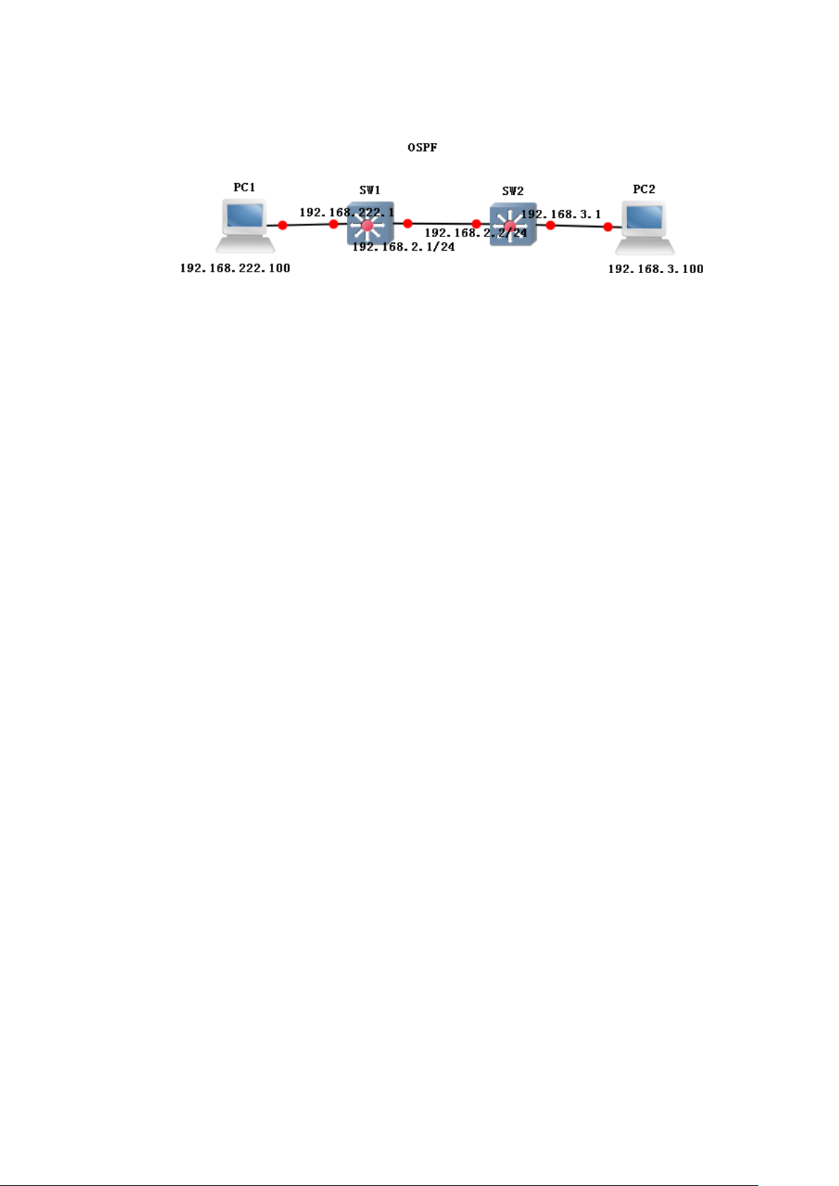
sw1:
switch(config)#interface vlanif1
switch(config-vlanif1)# ip address 192.168.222.1/24
switch(config)#interface vlanif2
switch(config-vlanif2)# ip address 192.168.2.1/24
switch(config-vlanif2)#exit
switch(config)#interface G22
switch(config-G22)# switchport mode access
switch(config-G22)# switchport pvid 2
switch(config)# router ospf
switch(config-ospf)# ospf router-id 1.1.1.1
switch(config-ospf)# network 192.168.2.0/24 area 0
switch(config-ospf)# network 192.168.222.0/24 area 0
sw1:
switch(config)#interface vlanif3
switch(config-vlanif3)# ip address 192.168.3.1/24
switch(config-vlanif3)#exit
switch(config)#interface G23
switch(config-G23)# switchport mode access
switch(config-G23)# switchport pvid 3
switch(config)#interface vlanif2
switch(config-vlanif2)# ip address 192.168.2.2/24
switch(config-vlanif2)#exit
switch(config)#interface G22
switch(config-G22)# switchport mode access
switch(config-G22)# switchport pvid 2
switch(config)# router ospf
switch(config-ospf)# ospf router-id 2.2.2.2
switch(config-ospf)# network 192.168.2.0/24 area 0
switch(config-ospf)# network 192.168.3.0/24 area 0
Page 78
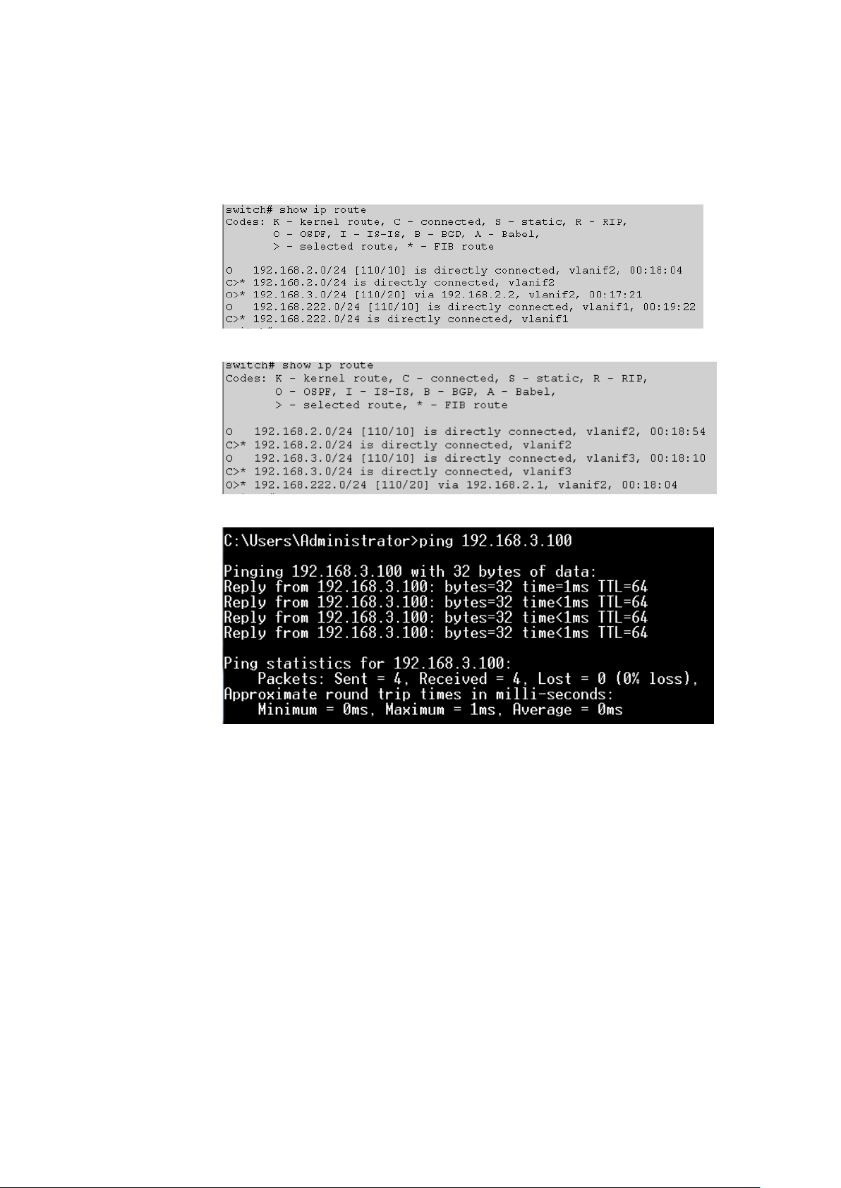
phenomenon:
//Display OSPF route
SW1:
SW2:
PC1 ping PC2
5.4 BGP config
BGP configuration commands include:
router bgp
timers bgp
redistribute
neighbor
Network
Function Brief
The border gateway protocol (BGP) is a routing protocol that runs on
TCP,which is a kind of autonomous system. BGP is the only protocol that is used to
Page 79

deal with the network size of the Internet, and is the only protocol that can properly
handle the multi connection between the routing domain.BGP is built on the
experience of EGP.The main function of the BGP system is to exchange network
reachability information with other BGP systems.The network reachability
information includes information of the autonomous system (AS) listed.These
information effectively construct the topology of AS interconnection and thus clears
the routing loop,At the same time, the AS level can be implemented in strategic
decision-making.
5.4.1 router bgp
Command Description
router bgp
//This command is enable BGP.
Parameter
None
Default
None
Command Mode
Interface configuration mode
Example
//This command is enable BGP.
switch(config)# router bgp 1
5.4.2 timers bgp
Command Description
timers bgp
//This command is to set up BGP update-time and max age.
Parameter
None
Default
Update-time:60
Max age:180
Command Mode
Interface configuration mode
Example
//Setting the BGP update time is 50s, the aging time is 150s.
switch(config)# router bgp 1
Page 80

switch(config-bgp)# timers bgp 50 150
5.4.3 redistribute
Command Description
redistribute
//This command is to set the BGP redistribution.
Parameter
None
Default
None
Command Mode
Interface configuration mode
Example
//This command is to set the BGP redistribution OSPF.
switch(config-bgp)# redistribute ospf
5.4.4 neighbor
Command Description
neighbor
//This command is to set up BGP neighbor information.
Parameter
None
Default
None
Command Mode
Interface configuration mode
Example
//This command is set the BGP neighbors to 192.168.222.222 belongs to AS1
switch(config)# router bgp 2
switch(config-bgp)# neighbor 192.168.222.22 remote-as1
5.4.5 network
Command Description
neighbor
//Set BGP neighbor information.
Parameter
None
Page 81
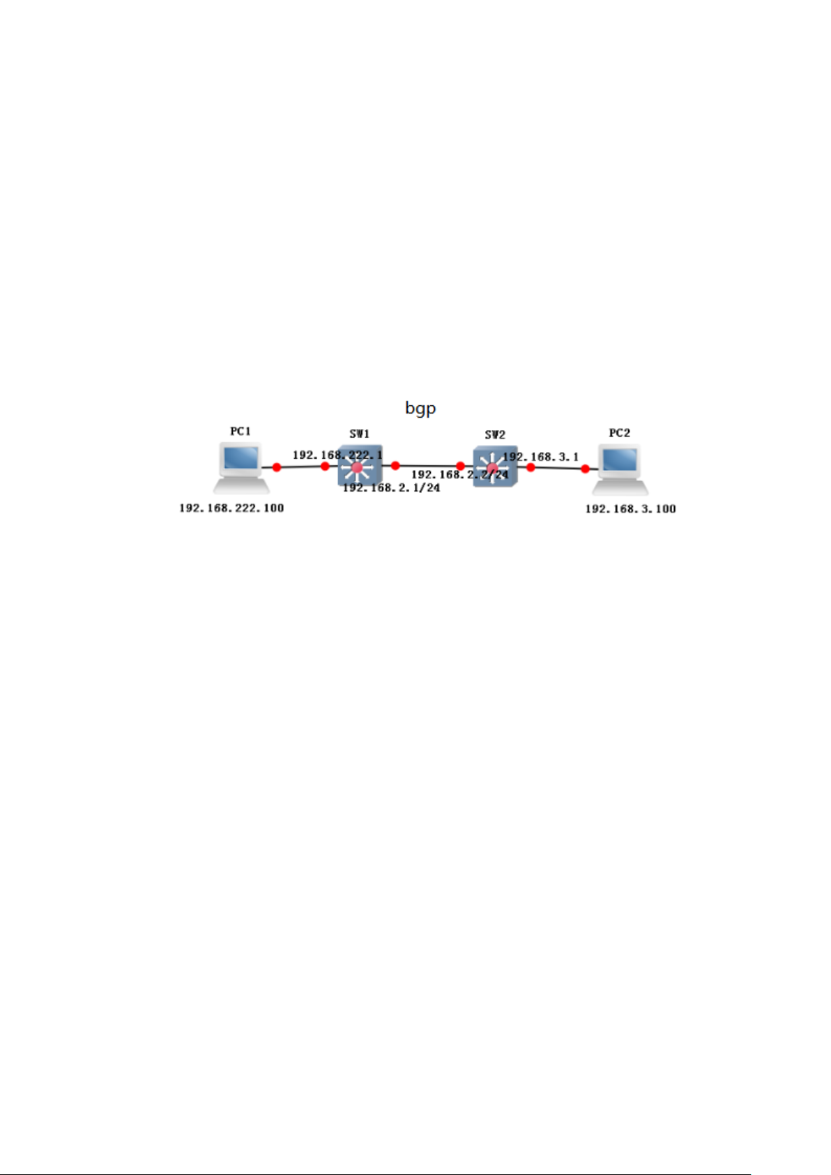
Default
None
Command Mode
Interface configuration mode
Example
//Declare the 192.168.3.0 network to BGP routing.
switch(config)# router bgp 1
switch(config-bgp)# network 192.168.3.0/24
5.4.6 example
sw1:
switch(config)# interface vlan1
switch(config-vlanif1)# ip address 192.168.222.1/24
switch(config)# interface vlan2
switch(config-vlanif2)# ip address 192.168.2.1/24
switch(config)# interface G2
switch(config-G2)# switchport pvid 2
switch(config)# router bgp 1
switch(config-bgp)# network 192.168.2.0
switch(config-bgp)# network 192.168.222.0
switch(config-bgp)# neighbor 192.168.2.2 remote-as 2
sw2:
switch(config)# interface vlan1
switch(config-vlanif1)# ip address 192.168.3.1/24
switch(config)# interface vlan2
switch(config-vlanif2)# ip address 192.168.2.2/24
switch(config)# interface G2
switch(config-G2)# switchport pvid 2
switch(config)# router bgp 2
switch(config-bgp)# network 192.168.2.0
switch(config-bgp)# network 192.168.3.0
Page 82

switch(config-bgp)# neighbor 192.168.2.1 remote-as 1
phenomenon:
sw1:
Sw2:
PC1 ping PC2
5.5 RIP config
RIP configuration commands include:
default-information
default-metric
distance
end
exit/quit
network
offset-list
passive-interface
redistribute
Page 83

Parameter
Parameters of the command mode
XX
Default 1 ,range 1-16
timers
version
Function Brief
RIP is Interior Gateway Protocol that more common used and used earlier.It is
suitable for small and similar network,and it is a typical distance vector protocol.RIP
exchange routing information through broadcast UDP messages,and it is send
routing information update every 30 seconds.RIP provides count Hop (hop count) as
a scale to measure routing distance.The hop count is the number of routers that a
packet must pass to reach the target.If the same target has two different speed or
bandwidth of the router, but the same hop count.Then RIP thinks that the two route
is equal distance.RIP maximum support of the number of hops is 15,the number of
hops 16 indicates that it is not reachable.
5.5.1 default-information originate
Command Description
//default-information originate
no default-information originate
Parameter
None
Default
None
Command Mode
Interface configuration mode
Example
Switch(config)#default-information originate
//Start rip to generate the default rip route function.
5.5.2 default-metric
Command Description
default-metric XX
no default-metric XX
Parameter
Default
None
Page 84

Parameter
Parameters of the command mode
XX
Range 1-255. Default 120
Command Mode
Interface configuration mode
Example
//This command is to set the default-metric to 5.
switch(config)# router rip
switch(config-rip)# default-metric 5
5.5.3 distance
Command Description
distance XX
Parameter
Default
120
Command Mode
Interface configuration mode
Example
//This command is to change administrative distance to 110.
switch(config)# router rip
switch(config-rip)# distance 110
5.5.4 end
Command Description
end
Parameter
None
Default
None
Command Mode
Interface configuration mode
Example
switch(config)# router rip
switch(config-rip)# end
Page 85

Parameter
Parameters of the command
mode
A.B.C.D/M
192.168.1.0/24
WORD
interface
5.5.5 exit/quit
Command Description
Exit/quit
Parameter
None
Default
None
Command Mode
Interface configuration mode
Example
switch(config)# router rip
switch(config-rip)# exit
5.5.6 network
Command Description
Network A.B.C.D/M
Network WORD
//Set the rip operating segments.
Parameter
Default
None
Command Mode
Interface configuration mode
Example
switch(config)# router rip
switch(config-rip)#network 192.168.1.0/24
5.5.7 offset-list
Command Description
Page 86

Parameter
Parameters of the command mode
acl-name
Call access control list name
In| out
Call ACL application direction
Metric
Set offset by default 1, range 1-16
If-name
Application of the rules of the
interface, the default all applications
offset-list <acl-name> {in | out} <metric> [<if-name>]
No offset-list <acl-name> {in | out} <metric> [<if-name>]
Parameter
Default
None
Command Mode
Interface configuration mode
Example
//The rule that calls the ACL1, the offset is set to 16 at G2 port import direction .
switch(config)# router rip
switch(config-rip)# offset-list 1 in 16 G2
5.5.8 passive-interface
Command Description
passive-interface <if-name>
//This command is to configure RIP passive-interface
No passive-interface <if-name>
//This command is disable RIP passive-interface
Parameter
None
Default
None
Command Mode
Interface configuration mode
Example
//this command is to configure vlan3 for passive-interface.
switch(config)# router rip
switch(config-rip)#passive-interface vlan3
Page 87

Parameter
Parameters of the command mode
protocol
The routing protocols that need to be
introduced into the RIP, such as IS-IS,
OSPF, BGP, static, connect, etc., are
introduced.
Metric
Specifies the metric value when the
route is introduced
Route-map
Route-map name to be referenced
when the route is introduced
Parameter
Parameters of the command mode
5.5.9 redistribute
Command Description
redistribute <protocol> [metric <metric>] [route-map <route-map>]
no redistribute <protocol> [metric <metric>] [route-map <route-map>]
Parameter
Default
None
Command Mode
Interface configuration mode
Example
//The introduction of the direct route to RIP routing table, and through the
route-map rule "list123" rule, the metric value of the specified route is 9.
switch(config)# router rip
switch(config-rip)#redistribute connected metric 9 route-map list123
5.5.10 timer
Command Description
timers basic <update-interval> <dead-interval> <garbage-interval>
no timers basic
//Change the time interval of the RIP periodic update packets, RIP route
waiting time, RIP routing is set to not be used to completely remove the time
interval from the routing table.
Parameter
Page 88

update-interval
RIP packet update interval , default 30S
dead-interval
RIP packet dead interval ,default 180S
garbage-interval
RIP packet garbage interval,default 120S.
Default
None
Command Mode
Interface configuration mode
Example
//The periodic update time of the configuration RIP protocol is 20 seconds, the
death time is 100 seconds, garbage collection time is 60 seconds.
switch(config)# router rip
switch(config-rip)#timers basic 20 100 60
5.5.11 version
Command Description
Version
//This command is to modify the RIP version .
Parameter
None
Default
None
Command Mode
Interface configuration mode
Example
//This command is to modify the RIP version for V2
switch(config)# router rip
switch(config-rip)#version 2
5.5.12 example
Network diagram as shown in Figure:
Page 89

sw1:
switch(config)#interface vlanif1
switch(config-vlanif1)# ip address 192.168.222.1/24
switch(config)#interface vlanif2
switch(config-vlanif2)# ip address 192.168.2.1/24
switch(config-vlanif2)#exit
switch(config)#interface G22
switch(config-G22)# switchport mode access
switch(config-G22)# switchport pvid 2
switch(config)# router rip
switch(config-rip)# network 192.168.2.0/24
switch(config-rip)# network 192.168.222.0/24
sw2:
switch(config)#interface vlanif3
switch(config-vlanif3)# ip address 192.168.3.1/24
switch(config-vlanif3)#exit
switch(config)#interface G23
switch(config-G23)# switchport mode access
switch(config-G23)# switchport pvid 3
switch(config)#interface vlanif2
switch(config-vlanif2)# ip address 192.168.2.2/24
switch(config-vlanif2)#exit
switch(config)#interface G22
switch(config-G22)# switchport mode access
switch(config-G22)# switchport pvid 2
switch(config)# router rip
switch(config-rip)# network 192.168.2.0/24
switch(config-rip)# network 192.168.3.0/24
phenomenon:
//Display RIP route
SW1:
SW2:
Page 90
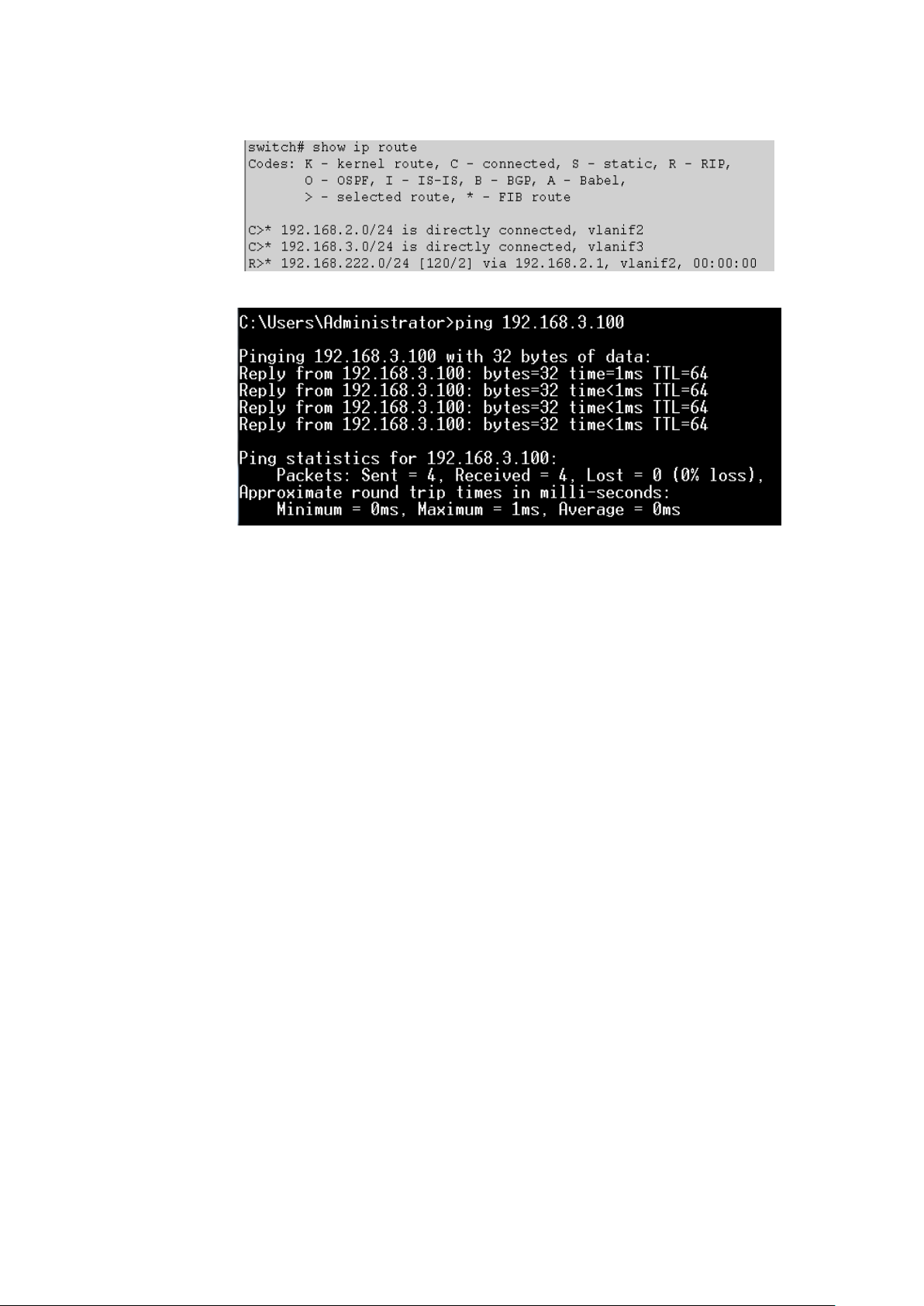
PC1 ping PC2
Page 91

6. Network security commands
6.1 Anti-attack
Anti-attack configuration commands include:
system ignore icmp-echo
system protection syn-ack
system rate-limit
Function Brief
Anti attack configuration is used to ignore the ICMP request for the
purpose of this device, The defense equipment TCP SYN attack and control
CPU data receiving threshold.
6.1.1 system ignore icmp-echo
Command Description
system ignore icmp-echo
no system ignore icmp-echo
//If you want to ignore the ICMP request for this device, it can be
configured by this command. Use the no form of the command to cancel this
configuration.
Parameter
None
Default
None
Command Mode
Global configuration mode
Example
//Configur ignores purpose for the ICMP request of this device .
switch(config)# system ignore icmp-echo
6.1.2 system protection syn-ack
Command Description
If you want to defend against this device SYN TCP attack, you can
configure this command. Use the no form of the command to cancel this
Page 92

Paramet
er
Parameters of the command mode
value
<0-100000> pps , default 0 :disable limited.
configuration.
system protection syn-ack
no system ignore icmp-echo
Parameter
None
Default
None
Command Mode
Global configuration mode
Example
//Configur defense against this device SYN TCP attack.
switch(config)# system protection syn-ack
6.1.3 system rate-limit
Command Description
system rate-limit value
no system rate-limit
//If you want to control the CPU of the received data value, you can use
this command to configure. Use the no form of the command to cancel this
configuration.
Parameter
Default
None
Command Mode
Global configuration mode
Example
//Configure the CPU data receiving threshold is 1000.
switch(config)# system rate-limit 1000
//Close the CPU data receiving threshold control function.
switch(config)# no system rate-limit
6.2 MAC binding
MAC binding configuration commands include:
Page 93

Parameter
Parameters of the command mode
mac-addr
It specifies the MAC address.
vlan-id
It specifies the VLAN to which the
MAC address belongs. The value
ranges from 1 to 4094.
interface-id
It specifies the physical port to which
the MAC address belongs.
mac-address static
6.2.1 mac-address static
Command Description
mac-address static mac-addr vlan vlan-id interface interface-id
//This command is used to add a static MAC address.
no mac-address static mac-addr vlan vlan-id
// This command is used to delete a static MAC address.
Parameter
Default
None
Command Mode
Global configuration mode
Example
//Run the following command to bind the MAC address 00-00-00-00-00-01 to port
10 that belongs to VLAN2:
switch(config)# mac-address static 00-00-00-00-00-01 vlan 2 interface T10
6.3 ARP binding
ARP binding configuration commands include:
ip-mac bind
show ip-mac bind
Function Brief
In order to r manage the computer bette in the network, you can use
the ARP binding function to control the network access (IP binding).
Note:
dynamic item when static binding.
Because it is a private function, showing in ARP table is still
Page 94

Parameter
Parameters of the command mode
interface-id
The physical port of the MAC address.
ip-addr
Ip address
mac-addr
MAC address
enable
Global switch on
disable
Global switch off
enable port
Port opening
eisable port
Port shutdown
add
adjunction
del
delete
6.3.1 ip-mac bind
Command Description
//This command is used to enable the ip-mac banding.
ip-mac bind enable
//This command is used to disable the ip-mac banding.
ip-mac bind disable
//This command is used to enacble IP - MAC banding on the interface.
ip-mac bind enable port interface-id
//This command is used to disable IP - MAC banding on the interface.
ip-mac bind disable port interface-id
//This command is used to add a ip-mac binding.
ip-mac bind add interface-id ip-addr mac-addr
//This command is used to delete a ip-mac binding.
ip-mac bind del ip-addr
Parameter
Default
None
Command Mode
Global configuration mode
Example
//This command is used to open the IP - MAC binding.
switch(config)# ip-mac bind enable
//This command is used to open IP - MAC binding in G2 .
switch(config)# ip-mac bind enable port G2
// Add a ip-mac binding.
Page 95

ip-addr
Ip address
config
Configuration
statistics
Static binding
table
list of bindin
switch(config)# ip-mac bind add G2 192.168.1.1 50-46-5D-E2-D5-50
6.3.2 show ip-mac bind
Command Description
//This command is used to display a IP ip-mac binding.
show ip-mac bind ip-addr
//This command is used to display the ip-mac configuration.
show ip-mac bind config
//This command is used to display the ip-mac bind.
show ip-mac bind statistics
//This command is used to display the ip-mac bind table.
show ip-mac bind table
Parameter
Default
None
Command Mode
Privileged mode
Example
//This command is used to display the ip-mac bind table.
switch(config)# show ip-mac bind table
6.4 ACL config
ACL configuration commands include:
mac acl
ip acl
rule
ip/mac access-group
Function Brief
ACLs are used to filter packets based on the configured packet matching
rules and processing operations. After an ACL is applied to a port, fields in each
packet are analyzed. After matched packets are identified, these packets are
processed according to the preset operations, such as permit, deny, rate limiting,
Page 96

Parameter
Parameters of the command mode
<1-99>
It specifies the ID of an MAC-ACL.
The value ranges from 1 to 99
Parameter
Parameters of the command mode
<100-999>
It specifies the ID of an IP-ACL. The
value ranges from 100 to 999
redirection, or port shutdown.
6.4.1 mac acl
Command Description
mac acl <1-99>
//This command is used to add an Mac-acl entry.
no mac acl <1-99>
//This command is used to delete an Mac-acl entry.
Parameter
Default
None
Command Mode
Global configuration mode
Example
switch(config)#mac acl 1
6.4.2 ip acl
Command Description
ip acl <100-999>
//This command is used to add an IP-ACL entry.
no ip acl <100-999>
//This command is used to delete an IP-ACL entry.
Parameter
Default
None
Command Mode
Global configuration mode
Example
switch(config)#ip acl 100
Page 97

Parameter
Parameters of the command mode
<1-127>
Rule number, range: 1-127
source mac
Source MAC address
destination mac
Destination MAC address,
1-4094
Vlan-id,range:1-4094
ETHTYPE
Ethernet type, range: 0x0000-0xFFFF;
0x0000 or do not fill in the representation
does not match the Ethernet type field,
source ip
Source IP address
destination ip
Destination IP address,
<0-7>
Match the IP priority, range 0-7
<0-15>
Match the TOS, range 0-15
<0-63>
Match the DSCP, range 0-63
6.4.3 rule
Command Description
rule <1-127> deny/permit <source mac> <destination mac> cos
<0-7>/vlan <1-4094>/eth_type ETHTYPE
rule <1-127> deny/permit icmp/igmp/tcp/udp/ip <source ip>
<destination ip> ip_pri<0-7> / tos_pri<0-15>/ dscp_pri<0-63>
//This command is used to add an ACL ACE entry.
no rulel <1-127>
//This command is used to delete an ACL ACE entry.
Parameter
Default
None
Command Mode
Global configuration mode
Example
//This command is used to add a Mac - acl rules.
switch(config)#mac acl 1
switch(config-acl-mac)#rule 1 deny any any
6.4.4 ip/mac access-group
Command Description
ip access-group <100-999>
no ip access-group <100-999>
mac access-group <1-99>
no mac access-group <1-99>
//Using this command, you can bind the port to use the ACL rule.
Parameter
Page 98

Parameter
Parameters of the command mode
<100-999>
ip acl group ID,range:100-999
<1-99>
mac acl group ID,range:1-99
Default
None
Command Mode
Interface configuration mode
Example
switch(config-G1)# ip access-group <100-999>
6.5 802.1X config
802.1X configuration commands include:
dot1x
dot1x auth-server
dot1x auth-server-type
dot1x acct-server
dot1x timer
dot1x auth-mode authorized-force/ auto/ unauthorized-force
dot1x controlled-mode based-on-mac/ based-on-port
dot1x auth
dot1x auth-user
Function Brief
802.1x was proposed by IEEE802 LAN/WAN Standards Committee
to resolve the security issues of the WLAN. Later this protocol is used on the
Ethernet as a common access control mechanism of LAN ports. 802.1x is
mainly used to resolve the authentication and security issues on the
Ethernet. It implements authentication and control on devices connected to
ports of the LAN access devices.
6.5.1 dot1x
Command Description
//This command is used to globally enable the 802.1x .
//This command is used to globally disable the 802.1x .
Dot1x
no Dot1x
Page 99

Parameter
Parameters of the command mode.
A.B.C.D
Ipaddress
secondary-ip
The standby server ip address.
Parameter
None
Default
Disable
Command Mode
Global configuration mode
Example
switch(config)#dot1x
6.5.2 dot1x auth-server
Command Description
dot1x auth-server ip A.B.C.D secondary-ip A.B.C.D port<PORT>
shared-secret< SECRET >
//The configuration of the authentication server IP address and IP address of the secret key
and the standby server.
Parameter
Default
Authentication server ip address:127.0.0.1
port number :1812
Key:radius
Command Mode
Global configuration mode
Example
switch(config)# dot1x auth-server ip 127.0.0.2 secondary-ip 127.0.0.3
port 1812 shared-secret 123
6.5.3 dot1x auth-server type
Command Description
dot1x auth-server type local/ remote
Parameter
None
Default
Remote
Page 100

Parameter
Parameters of the command mode.
A.B.C.D
IP address .
secondary-ip
The standby server ip address.
Parameter
Parameters of the command mode
value
Unit: second, range: 1-65535, aging update time
reauth-period
Authentication update interval time
quient-period
Quiet period update interval
Command Mode
Global configuration mode
Example
switch(config)#dot1x auth-server-type local
switch(config)#dot1x auth-server-type remote
6.5.4 dot1x acct-sever
Command Description
dot1x acct-sever ip A.B.C.D secondary-ip A.B.C.D port<PORT>
shared-secret< SECRET >
//Configure the billing server IP address and the standby server IP address and
secret key.
Parameter
Default
Remote
Command Mode
Global configuration mode
Example
switch(config)# dot1x acct-sever ip 127.0.0.2 secondary-ip 127.0.0.3 port
1812 shared-secret 123
6.5.5 dot1x timer
Command Description
dot1x timer reauth-period/quient-period value <1-65535>
//Configure authentication server update interval /hold authentication time.
Parameter
Default
This command is to reauth-period is 3600s
 Loading...