

Page 1

Light-Duty Housing User’s Manual
Version 1.2.0
Page 2

i
Table of Contents
1 GENERAL INTRODUCTION .............................................................................. 1
1.1 Overview ................................................................................................................................................. 1
1.2 Features .................................................................................................................................................. 1
1.3 Dimensions ............................................................................................................................................. 1
2 HOUSING INSTALLATION INSTRUCTION GUIDE ........................................... 3
2.1 Lock/Unlock Housing ............................................................................................................................ 3
2.2 Camera Installation ............................................................................................................................... 3
2.3 Cable Connection .................................................................................................................................. 4
3 BRACKET INSTALLATION GUIDE .................................................................... 6
3.1 General Bracket Installation ................................................................................................................. 6
3.2 Special Bracket Installation (Compact design, concealed cable exit) ........................................... 6
3.3 Bracket Types ........................................................................................................................................ 7
4 SPECIFICATIONS .............................................................................................. 9
APPENDIX TOXIC OR HAZARDOUS MATERIALS OR ELEMENTS ..................... 10
Page 3

ii
Welcome
Thank you for purchasing our housing!
Please read the following safeguards and warnings carefully before you install or use the
product!
Page 4

iii
Important Safeguards and Warnings
1.Electrical safety
All installation and operation here should conform to your local electrical safety codes.
We assume no liability or responsibility for all the fires or electrical shock caused by improper
handling or installation.
2.Transportation security
Heavy stress, violent vibration or water splash are not allowed during transportation, storage and
installation.
3.Installation
Do not apply power to the housing before completing installation.
Do not place objects on the housing.
4.Qualified engineers needed
All the examination and repair work should be done by the qualified service engineers.
We are not liable for any problems caused by unauthorized modifications or attempted repair.
5.Environment
The housing should be installed in a cool, dry place away from direct sunlight, inflammable,
explosive substances and etc.
Please keep sound ventilation.
6. Accessories
Be sure to use all the accessories recommended by manufacturer.
Before installation, please open the package and check all the components are included.
Contact your local retailer ASAP if something is broken in your package.
Page 5
1
1 General Introduction
1.1 Overview
The light–duty housing (“housing”) adopts all-weather compact design. It can install camera and
lens of various dimensions. It has built-in camera mounting plate. The IP66 compliance is
suitable for various environments.
1.2 Features
Compact design, concealed cable exit.
Glass waterproof coat finish.
All aluminum construction, waterproof design, IP66 compliance.
Module design, support various function combinations.
IR module is for 50M/100M distance both.
All-weather wiper module, built-in heating module.
Optional installation modes and brackets.
Suitable for cameras, block camera and ITS products of various dimension.
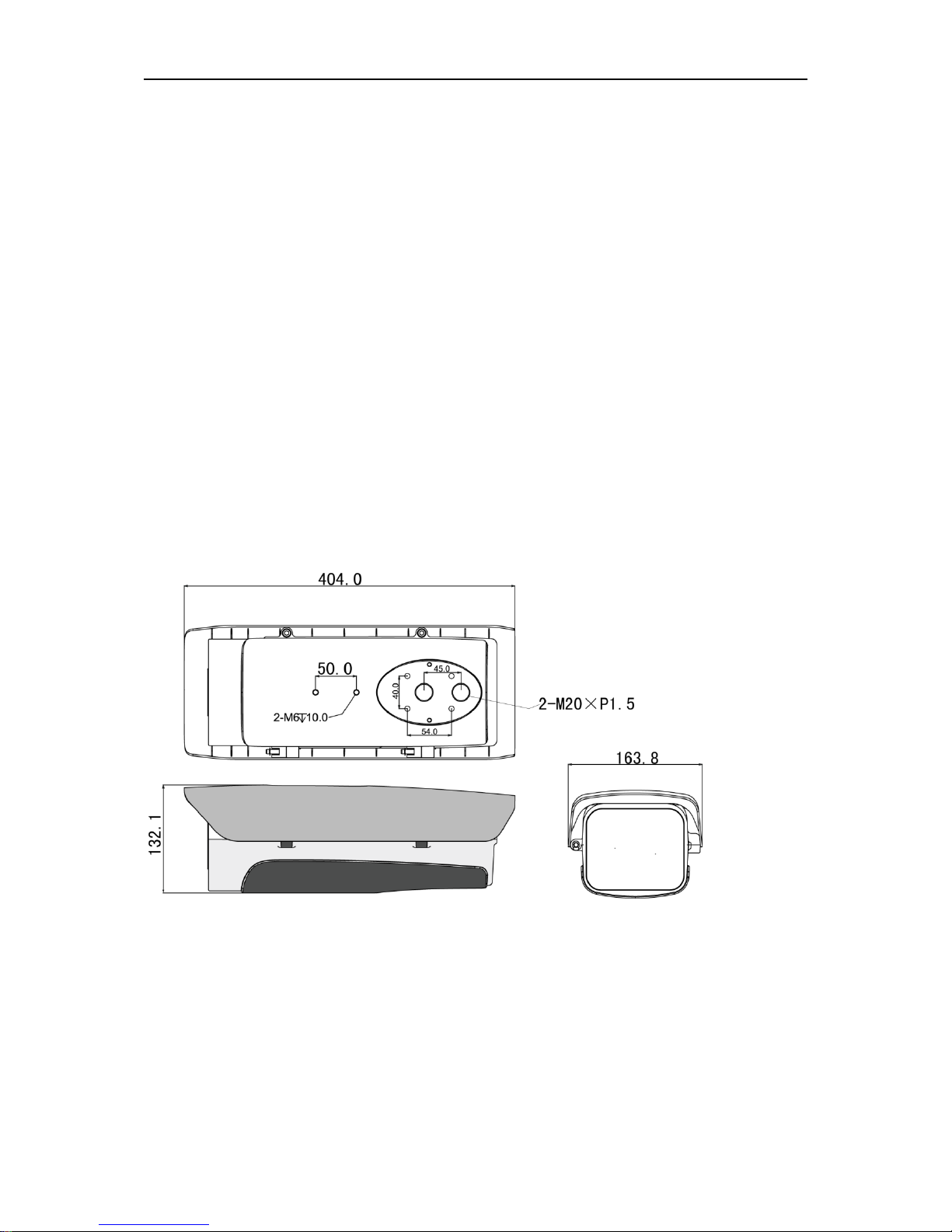
1.3 Dimensions
The dimensions of PFH610N and DH-PFH610N-H are shown as below. The unit is mm. See
Figure 1-1.
Figure 1-1
The dimensions of PFH610N-IR are shown as below. The unit is mm. See Figure 1-2.
Page 6

2
Figure 1-2
The dimensions of PFH610N-W and PFH610N-IR-W are shown as below. The unit is mm. See
Figure 1-3.
Figure 1-3
Page 7

3
2 Housing Installation Instruction Guide
2.1 Lock/Unlock Housing
You can use inner hex wrench (5.0mm) to fix or loosen the two M6 screws on both sides of the
housing to lock or unlock the housing. See Figure 2-1.
Figure 2-1
Important
Before you lock the housing, please make sure the waterproof gasket is in the right
position. See Figure 2-2. Otherwise it may affect the waterproof capability of the housing.
Figure 2-2
2.2 Camera Installation
Step 1: Take the camera bracket from the housing.
Step 2: Fix the camera on the camera bracket.
Step 3: Secure the camera bracket on the case. See Figure 2-3.
Note
Page 8

4
The camera lens shall be as near as to the inside of the glass (Recommended distance is 13mm.) in case it affect the lens view angle.
The camera bracket supports upside down installation
Please refer to the following sheet for detailed information.
SN
Name
1
Camera
2
Screws to secure the camera bracket. (M3×
8 combination screw)
3
Camera bracket
4
Screws to secure the camera (1/4-20×6UNC
pan head screws.)
Figure 2-3
2.3 Cable Connection
Please refer to the following figure for cable connection information of modules. See Figure 2-4.
Note
PFH610N does not include the module. Please contact your local retailer for more information.
Important
Do not connect C/NO port to the IR/G port. It may result in IR light damage.
The input power sourcing shall be AC 24V when there is IR module and wiper module.
The wiper shall work on the 50Hz environment.
Please refer to the following sheet for detailed information.
Port
Port Function
C/NO
Wiper control port. Connect to the NO port of the camera.
IR/G
IR light indicator light.
When the IR light is on, the voltage between IR and G is
Page 9

5
Port
Port Function
3.4±0.1V. The voltage is 0V when the IR light is off.
CAM1/CAM2
Power output port. It is the same as the voltage of the external
power supplying source.
AC24V/DC12V
Power input port. Connect to external power sourcing.
Figure 2-4
Page 10
6
3 Bracket Installation Guide
3.1 General Bracket Installation
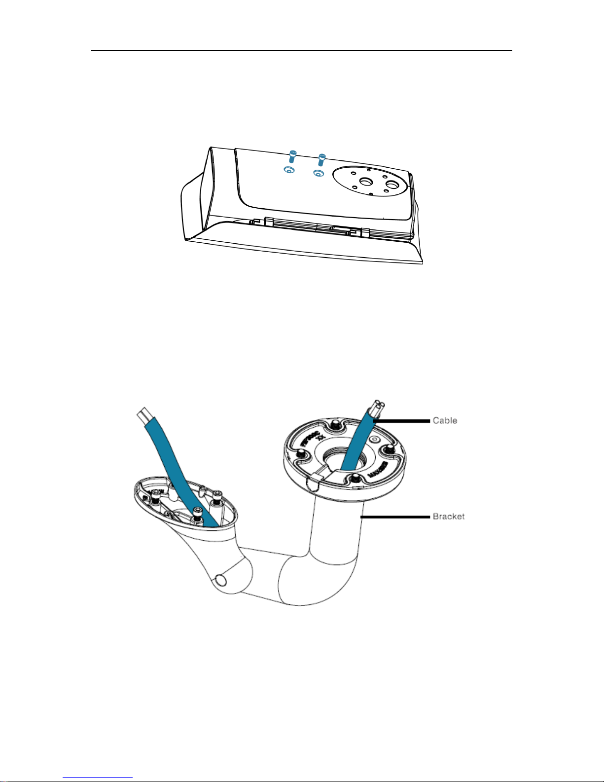
The housing can use the bracket of the thread hole to install. The general bracket thread hole
(M6) on the housing is shown as below. See Figure 3-1.
Figure 3-1
3.2 Special Bracket Installation (Compact design, concealed cable exit)
Step 1: Pull the cable through the inside of the bracket. See Figure 3-2.
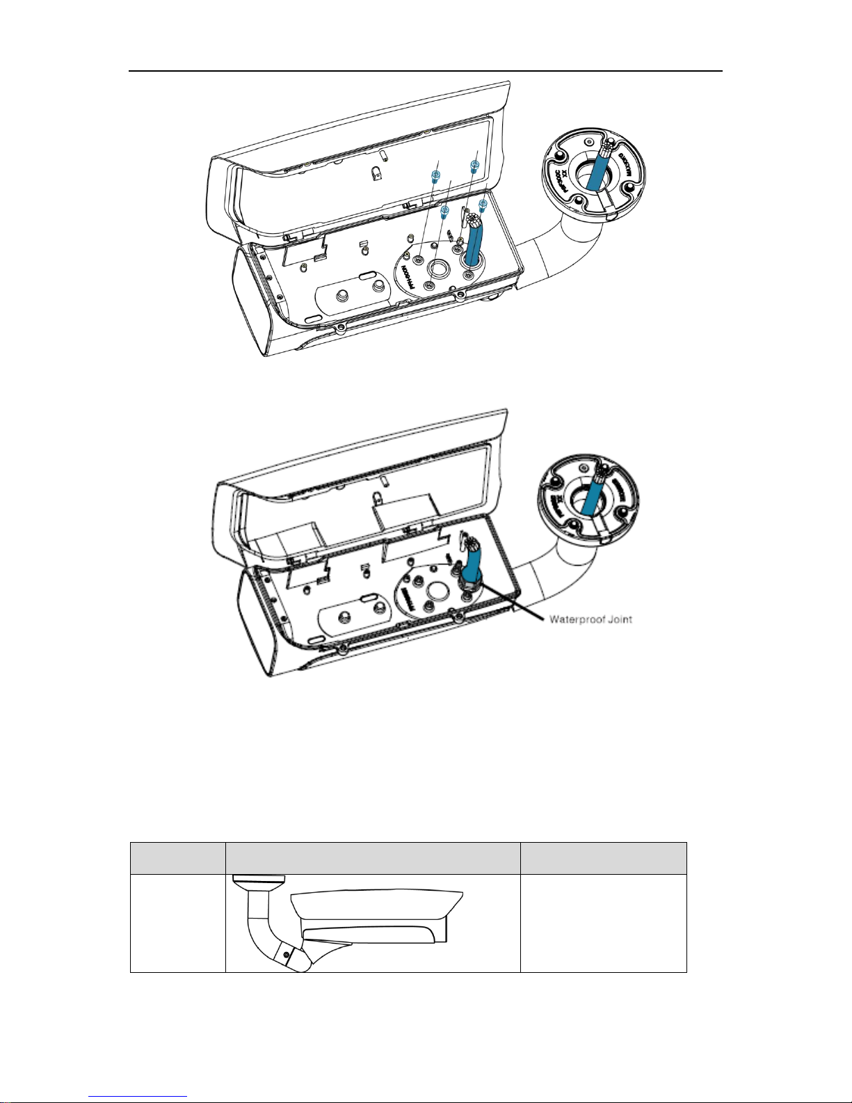
Step 2: Secure the bracket on the housing. See Figure 3-3.
Step 3: Put the waterproof joint on the cables and then secure firmly. See Figure 3-4.
Figure 3-2
Page 11
7
Figure 3-3
Figure 3-4
3.3 Bracket Types
You can refer to the following sheet for different bracket models if you want to use different
mount modes.
Installation
Mode
Reference Figure
Bracket Model
Ceiling
Mount
PFB600W
Page 12

8
Installation
Mode
Reference Figure
Bracket Model
Wall Mount 1
PFB602W
Pedestal
Mount
PFA160
Pedestal
Mount 1
The bracket and the housing installation
position adopt symmetric design. The bracket
can be installed upside-down.
PFB601W
Pedestal
Mount 2
PFB601W+PFA112
(200mm)or PFA113
(400mm)
The bracket is not a standard accessory of the housing. Please contact your local retailer
for more information.
Page 13

9
4 Specifications
Product Model
DHPFH610N
DHPFH610V
DHPFH610NH
DHPFH610VIR
DHPFH610NIR
DHPFH610NIR-W
DHPFH610NW
Dimensions
404mm×16
4mm×132
mm
404mm×16
4mm×132m
m
404mm×16
4mm×132
mm
404mm×16
4mm×132
mm
404mm×16
4mm×132
mm
404mm×16
4mm×175
mm
404mm×16
4mm×175
mm
Camera Max
Dimensions
220mm×86
mm×90mm
220mm×86
mm×90mm
220mm×86
mm×90mm
171mm×86
mm×90mm
171mm×86
mm×90mm
171mm×86
mm×90mm
171mm×86
mm×90mm
Window Area
100mm×80
mm
100mm×80
mm
100mm×80
mm
φ50mm
φ50mm
φ50mm
100mm×80
mm
Weight
2.5Kg
2.5Kg
2.7Kg
3.0Kg
3.0Kg
3.5Kg
3.0Kg
Material
AL+PC
AL+PC
AL+PC
AL+PC
AL+PC
AL+PC
AL+PC
Protection
Level
IP66
IP66
IP66
IP66
IP66
IP66
IP66
Installation
Environments
Indoor/Out
door
Indoor/Outd
oor
Indoor/Out
door
Indoor/Out
door
Indoor/Out
door
Indoor/Out
door
Indoor/Out
door
Working
Temperature
-30℃~
+60℃
-30℃~
+60℃
-30℃~
+60℃
-30℃~
+60℃
-30℃~
+60℃
-30℃~
+60℃
-30℃~
+60℃
Working
Humidity
<90%,no
condensati
on
<90%,no
condensatio
n
<90%,no
condensati
on
<90%,no
condensati
on
<90%,no
condensati
on
<90%,no
condensati
on
<90%,no
condensati
on
Working
Voltage
N/A
N/A
AC24V
AC24V
AC24V
AC24V
AC24V
Working
Current
N/A
N/A
2.5A
2.5A
2.5A
2.5A
2.5A
Auto
Temperature
Control
Range(Heating)
N/A
N/A
ON:5±5℃/
OFF:
15±5℃
N/A
N/A
N/A
ON:5±5℃/
OFF:
15±5℃
Auto
Temperature
Control
Range(Blower)
N/A
N/A
ON:37±5℃
/OFF:
20±5℃
ON:37±5℃
/OFF:
20±5℃
ON:37±5℃
/OFF:
20±5℃
ON:37±5℃
/OFF:
20±5℃
ON:37±5℃
/OFF:
20±5℃
IR Distance
N/A
N/A
N/A
0-100M
0-100M
0-100M
N/A
Wiper
N/A
N/A
N/A
N/A
N/A
YES
YES
Vandal Proof
N/A
YES
N/A
YES
N/A
N/A
N/A
Page 14

10
Appendix Toxic or Hazardous Materials or Elements
Component
Name
Toxic or Hazardous Materials or Elements
Pb
Hg
Cd
Cr VI
PBB
PBDE
Sheet Metal
○ ○ ○ ○ ○ ○
Plastic Parts
○ ○ ○ ○ ○ ○
PCB
○ ○ ○ ○ ○
○
Connection
Cable
○ ○ ○ ○ ○ ○
Accessories
○ ○ ○ ○ ○ ○
Note
O: Indicates that the concentration of the hazardous substance in all homogeneous materials in
the parts is below the relevant threshold of the SJ/T11363-2006 standard.
X: Indicates that the concentration of the hazardous substance of at least one of all
homogeneous materials in the parts is above the relevant threshold of the SJ/T11363-2006
standard. During the environmental-friendly use period (EFUP) period, the toxic or hazardous
substance or elements contained in products will not leak or mutate so that the use of these
(substances or elements) will not result in any severe environmental pollution, any bodily injury or
damage to any assets. The consumer is not authorized to process such kind of substances or
elements, please return to the corresponding local authorities to process according to your local
government statutes.
Note
This manual is for reference only. Slight difference may be found in the user
interface.
All the designs and software here are subject to change without prior written
notice.
All trademarks and registered trademarks mentioned are the properties of their
respective
owners.
If there is any uncertainty or controversy, please refer to the final explanation of us.
Please visit our website or contact your local service engineer for more
information.
 Loading...