

Page 1

46” (LED) Super Narrow Bezel Video Wall
Central Control Solution
ZheJiang Dahua Technology CO.,LTD.
2012.07
Page 2

ii
Table of Contents
1 Summary ...................................................................................................................... 1
1.1 System Overview ............................................................................................... 1
1.2 Idea of Design.................................................................................................... 1
1.3 Hardware ........................................................................................................... 1
1.3.1 Display Dimension .................................................................................. 1
1.3.2 Equipment List ........................................................................................ 2
1.3.3 System Structure .................................................................................... 3
2 System Function ........................................................................................................... 4
2.1 Function Overview ............................................................................................. 4
2.2 Signal Display .................................................................................................... 5
2.3 Controlling Software .......................................................................................... 6
2.3.1 Software Interface................................................................................... 7
2.3.2 Software Function ................................................................................... 7
3 Main Device Intro .......................................................................................................... 9
3.1 DHL460UTS-E ................................................................................................... 9
3.1.1 Panel Features ....................................................................................... 9
3.1.2 Product Features .................................................................................. 10
3.1.3 Specifications ........................................................................................ 10
3.2 Central Control System ................................................................................... 12
3.2.1 Product Function................................................................................... 12
3.2.2 Port ....................................................................................................... 12
3.2.3 Specifications ........................................................................................ 13
3.3 DH-NVS0404DH .............................................................................................. 13
3.3.1 Product Traits ....................................................................................... 13
3.3.2 Specifications ........................................................................................ 14
3.4 Matrix ............................................................................................................... 15
3.4.1 Function and Application ...................................................................... 15
3.4.2 VGA Matrix Parameter ......................................................................... 15
3.5 DH-VGA0102 Distribution Amplifier ................................................................ 16
3.5.1 Product Intro ......................................................................................... 16
3.5.2 Specifications ........................................................................................ 16
3.5.3 Connection Overview ........................................................................... 17
4 Requirement for Installation ....................................................................................... 17
4.1 Project Preparation and Environment Requirements...................................... 17
4.1.1 Requirement for Power Supply ............................................................ 17
4.1.2 Requirements of Air-conditioning ......................................................... 18
4.1.3 Requirements of Temperature and Humidity ....................................... 20
4.1.4 Light Requirements .............................................................................. 20
4.1.5 Decoration Requirements ..................................................................... 20
4.1.6 Requirements of Maintenance Channel and Floor of Video Wall Display
System Device .................................................................................................... 21
4.1.7 Requirements of Load-Bearing ............................................................ 21
Page 3

iii
4.1.8 Requirements of Anti-Dust ................................................................... 22
4.1.9 Requirements of Ground Connection ................................................... 22
4.1.10 Requirements of Fire Fighting .............................................................. 22
4.1.11 Requirements of Mechanical Shock and Vibration .............................. 22
4.1.12 Requirements of Magnetic Field ........................................................... 22
4.1.13 Requirements of Integrated Wiring ....................................................... 23
4.1.14 Requirements of Fixing Video Wall ...................................................... 23
4.2 Technical Training ........................................................................................... 23
Appendix 1: Company Overview ....................................................................................... 24
Appendix 2: Principal of Model Selection of Video Wall Display Plan (PDP/LCD/DLP/
Projection Combined) ........................................................................................................ 26
Appendix 3: Reference of Video Wall Design ................................................................... 28
Page 4

1
1 Summary
1.1 System Overview
This video wall central control solution takes mainly economy and stability into
consideration and adopts the most stable B/S structure. Client may directly access server
end via WEB and. Within the LAN, user may operate the server via different client ends
without influences of PC. It eliminates control software problems due to PC breakdown.
The system can integrate video matrix/RGB matrix and other devices which accomplish
management and control of video wall splicing system. User also can connect to video
wall from iPad or any portable wireless terminal. The solution supports wired and wireless
access to video wall application.
1.2 Idea of Design
Economic: low cost, durability, low maintenance lost.
Stable: embedded structure, free from external environments effect.
Display Effect: High resolution, multi-layers, bright color.
Recognition: Splicing Video Wall has been adopted in many fields with high
recognition and easy operation.
Environment-friendly: low power consumption, durability, zero harmful ingredients,
full metal surface, zero radiation.
Reliability: authenticated by various professional tests and internal examinations; the
system is designed to promote compatibility and redundancy function.
1.3 Hardware
According to development need of xxxx control monitor center and to accomplish central
control, we recommend the 2x2 video splicing wall---DHL460UTS-E. It well fulfills the
development objective of control monitor center, requirements of physical environment
and technology, and follows principle of advancement, reliability, durability, compatibility,
extendibility and economy.
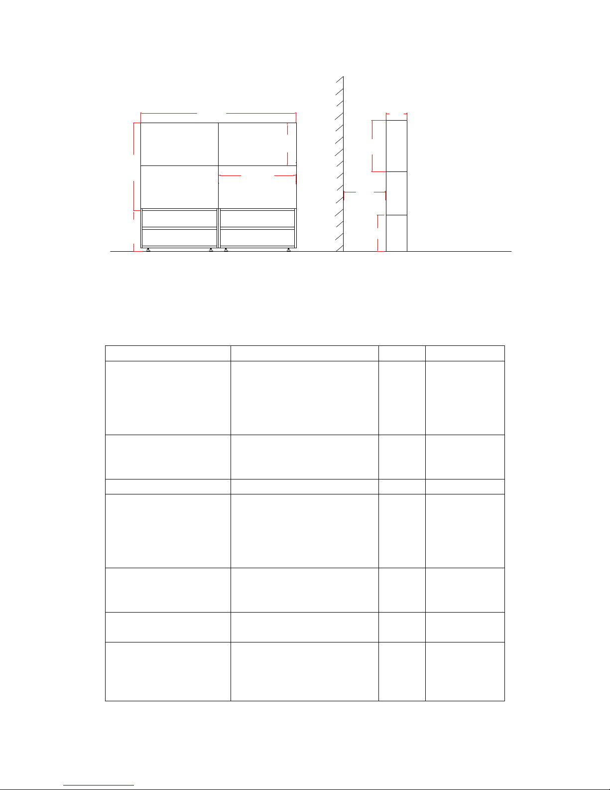
1.3.1 Display Dimension
The display dimension of DHL460UTS-E is shown in Figure 1- 1.
Page 5
2
2048.0
1024.0
578.6
1157.21000
578.6
1000
245
1000
Figure 1- 1
1.3.2 Equipment List
Name
Description
Quantity
Demand
DHL460UTS-E
LCD Unit; double side splicing
5.7mm, brightness 450 cd/㎡,
LED backlight, super high
resolution, network decoder
module (optional)
4
Mandatory
DHM-VGA0808
RGB matrix, for input/output
switch of PC signal. High band
width, anti-cross file.
1
Mandatory
DH-VNS0404DH
Embedded digital HD decoder
1
Mandatory
DH-VWC
Central control system, to
manage video wall system and
matrix. B/S structure, Web
control; pure hardware
structure, no OS
1
Mandatory
Embedded Multi-Screen
Control Software
Video wall setup and daily
usage, may set preview format,
boot up/shut down and etc.
1
Mandatory
Project Wiring
Professional anti-interference
project wiring
1
Mandatory
DH-VGA0102 distribution
magnifier VGA output
High performance VGA
distribution magnifier: one VGA
input, one VGA local play, one
VGA remote send
4
Mandatory
Page 6
3
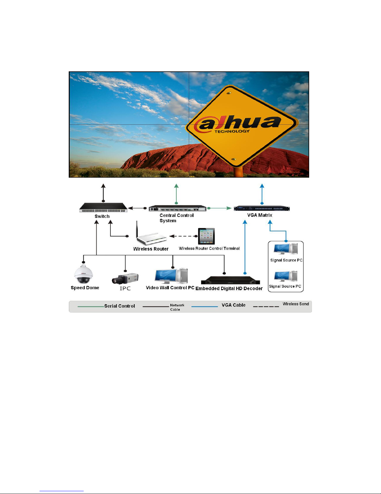
1.3.3 System Structure
The system structure is shown in Figure 1- 2.
Figure 1- 2
Page 7
4
2 System Function
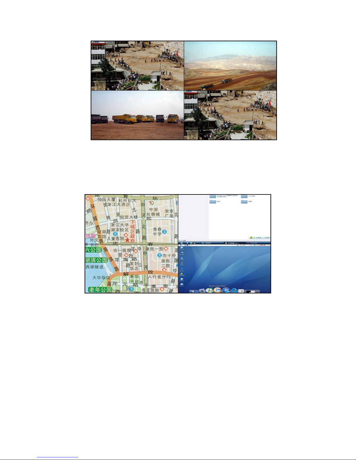
2.1 Function Overview
The video wall is capable in functions of single screen, partial full screen, full screen
splicing of analog video, computer signal. See Figure 2- 1.
Figure 2- 1
Core of control adopts embedded device, which is stable and safe, effectively
eliminate problems such as virus and crash of windows system within operation of
video wall.
During construction, you just need one network cable to display the HD network video
stream signal on the video wall. It is free of the complicated cable layout, and the
signal quality decreasing resulting from the repeated decoding. . Detailed steps as
the following:
IP speed dome, network camera and other encode signal are sent into display unit
via switch, processed by HD decode module embedded in display unit, is able to
display 1-16 split scene, supporting any tour monitoring. See Figure 2- 2.
Figure 2- 2
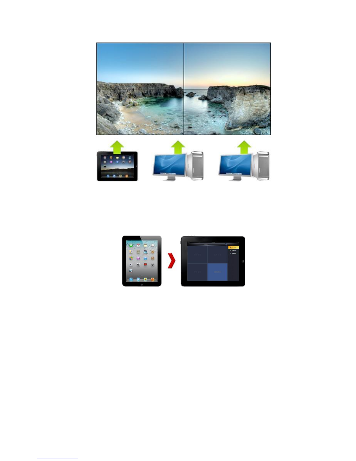
When the video wall is connected, it supports multi-operators of video wall at the
same time. See Figure 2- 3.
Network
Decode
Page 8
5
Figure 2- 3
Protocol is open and the controlling software of video wall can be integrated to the
security platform software.
The video wall support iPad and other tablet computers’ wireless control function.
See Figure 2- 4.
Figure 2- 4
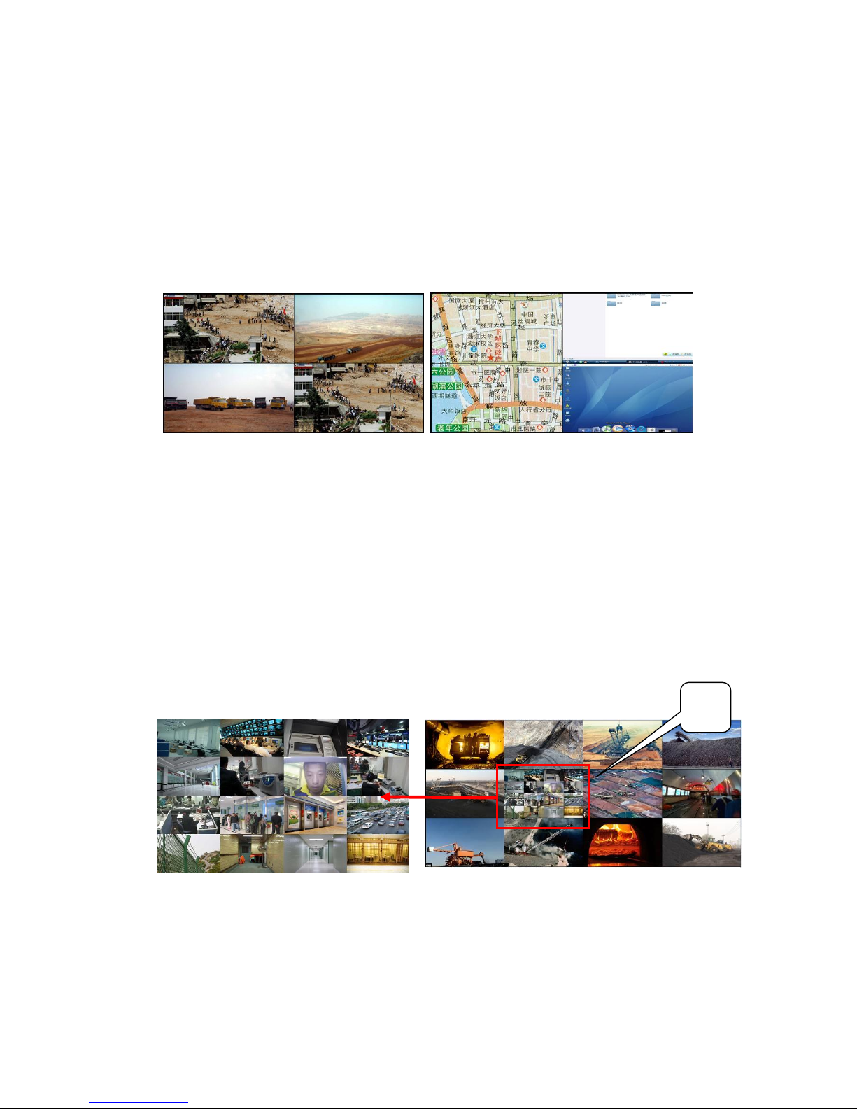
2.2 Signal Display
The video wall central control system is connected to video wall via serial. PC and laptop
is connected to input port of RGB matrix via special cable, and RGB output port is
connected to video wall display unit. The window supports single screen, partial full
screen, and full screen splicing. See Figure 2- 5.
Page 9
6
Figure 2- 5
Analog camera, DVD, network video decoder and other video signals insert to input port
of video matrix and output port of video matrix is connected to video wall display unit. The
window supports single screen, partial full screen, and full screen splicing. See Figure 2-
6.
Figure 2- 6
RGB matrix and video matrix are connected to video wall central control system via serial.
Control port is connected to the network interface of central control system via Internet or
wireless access to central control system.
2.3 Controlling Software
Video wall controlling software DH-VWC adopts B/S structure. Any PC within LAN can
access, config and operate via IE without installation of any client software. It eliminates
risks of control from a single PC. DH-DSCS software also can smoothly operate on the
new wireless terminal developed by Dahua. User can control video wall from pad, mobile
phone and other portable control terminal.
Page 10
7
2.3.1 Software Interface
The software interface is shown in Figure 2- 7.
Figure 2- 7
2.3.2 Software Function
Server
1) Window: Support adding and deletion of window, splicing zoom in, signal switch
and etc.
2) Preview format management: Support display splicing preview format setup,
max 20 and support user custom and schedule.
3) Signal source management: Signal source classification, rename, and matrix
mapping config.
4) Matrix management: Support domestic mainstream brands’ VGA matrix, DVI
matrix and video matrix; support user custom, manual matrix control of command
head, body and tail to achieve management over non-custom matrix.
5) Display unit: (LCD row column, port setup), support manual boot up and shut
down, schedule and signal switch.
6) Password management: Support custom of password.
7) Right management: Functions under each right group vary.
8) Third party support: Support third party development.
9) Serial setup: Basic parameter (bit rate, check bit and etc.) setup.
10) Backup management: Support backup and online upgrading.
Page 11

8
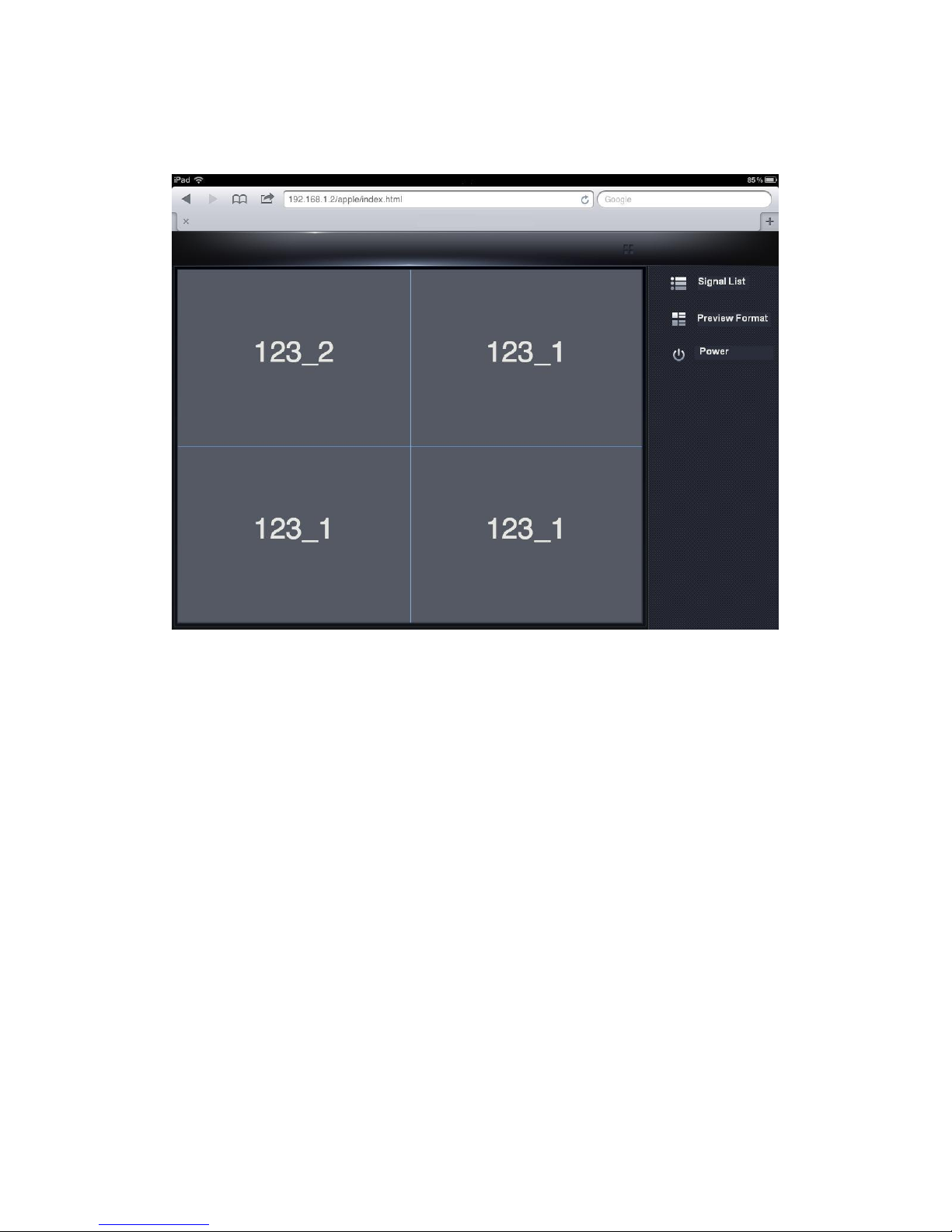
Touch Control Terminal
1) Support touch control mode with identification of various touch command.
2) Operation interface can be customized by user.
3) It does not influence functions carried by pad itself.
See Figure 2- 8.
Figure 2- 8
Page 12

9
3 Main Device Intro
3.1 DHL460UTS-E
3.1.1 Panel Features
5.7mm Super Narrow Bezel
DHL460UTS-E’s physical seam is 5.7 mm, which is more advanced than
DHL460UT(CCFL) Super Narrow Bezel, and will give you superior experience of supper
narrow bezel vision. Please see Figure 3- 1.
6.7mm 5.7mm
DHL460UT(CCFL) DHL460UTS-E
Figure 3- 1
FHD Full HD Resolution
Comparing to DHL460UT(CCFL), DHL460UTS-E has fulfilled full HD resolution
(FHD). With FHD, you will watch video as more colorful, vivid and clear. Please see Figure
3- 2.
DHL460UT(CCFL) DHL460UTS-E
Figure 3- 2
Page 13

10
Power-Saving LED Back Light
DHL460UT-E adopts LED irradiance diode back light mode, its power consumption is
merely 133W, much lower than traditional CCFL. Please see Figure 3- 3.
DHL460UT(CCFL) DHL460UT-E
Figure 3- 3
3.1.2 Product Features
Industrial Level DID LCD panel, suitable for 7*24 continuous works.
Super narrow bezel. Suitable for splicing application.
High contrastness, high brightness greatly enhances the video layer, and presents
the details of the video.
High fidelity digital, brilliant and vivid video.
Build-in 3D COMB filter and 3D Noise Reduction
Abundant interfaces, support video signal loop
Built-in picture splicing function
Infrared, RS232 double control mode, supporting remote PC control
Fan smart detection, OSD prompt.
Brightness smart detection, environment-friendly
Anti-interference mental case, no radiation
Professional cooling design, increase device life span
Built-in power supply, low power consumption, super low noise
Fast stack installation, professional project design, supporting arc-shaped mounting
Widely used in monitor center, control platform and safe city
3.1.3 Specifications
Parameter/Model
DHL460UT
Diagonal Length
46"(16:9)
Type
S-PVA(FHD)
Resolution
1920×1080
Dot Pitch
0.53025(H)×0.53025(V)
Page 14

11
Physical Seam
5.7mm (Upper left:3.8 Lower right:1.9)
Optical Seam
5.9mm
Back Light Mode
LED
Brightness(Standard)
700 cd/㎡ or 450 cd/㎡
Contrastness
3500:1
Viewing Angle
(horizontal/vertical)
178/178
Respond Period (Grey
Scale)
8ms
Color Gamut (CIE1931)
72%
Color Display
16.7M/8bit
Color Saturation
92%
Video Input
CVBS(BNC)×2
PC Signal
VGA(D-Sub)×1
Net Video Decode Signal
(Optional)
RJ45,HD H.264 Video Decode Signal
Digital Signal
DVI×1 [1080P(1920×1080), compatible downward]
HDMI×1 [1080P(1920×1080), compatible downward]
Signal Circulating
CVBS(BNC)×2
Power
Consumption(Normal)
133W
Standby Power
Consumption
≤1W
Power Management
AC100-240V~(+/-10%),50/60 Hz
Installation
Modular Stacking/ Cabinet installation (Back up)
Cooling System
Industrial Cooling Fan
Control Mode
RS232 serial control,one way loop,infrared remote
control
Frame Color
Black
Case Material
Metal
Gross Weight (including
Structural parts)
22.5kg
Unit Dimension(mm)
1024.0×578.6×245.0
Display Area(mm)
1018×573
Package Dimension (mm)
1235×820×460
MTBF
50,000 Hours
Page 15

12
Work Environment
Temperature:0℃~50℃
Humidity:20%~95%
Altitude:0-23000 ft
Storage Environment
Temperature:-25℃~70℃
Humidity:60%~75%
Altitude:0-43000ft
Features
Double-bezel physical seam 5.7mm
Build-in industrial level fan
High and low current are installed respectively
infrared remote control
Remote PC centralized control
Actual dimension may vary depends on order.
3.2 Central Control System
3.2.1 Product Function
B/S structure, Web control, no limit on OS platform
Pure hardware structure, no OS, no virus, high stability
Seamless integration with current plasma/LCD/DLP
Server end supports wired and wireless connection.
Dual network card input to improve efficiency.
Multiple serial output to control several devices at the same time
Config iPad, panel computer and other portable wireless control terminal, support
touch control.
Integrate control over video matrix/RGB matrix, switch with display unit
Provide universal public SDK, support third party development
3.2.2 Port
The device port is shown in Figure 3- 4 and Figure 3- 5.
Figure 3- 4
Page 16

13
Figure 3- 5
3.2.3 Specifications
Control
Input/output
2-ch 100M RJ-45
Control Output
Port
8-ch serial control signal output, 6*RS232 (5*D89 male+1*D89
female), 2*RS485, serial adjustable.
Update Port
One USB.2.0 port for update
Power(Energy)
AC100-240V@50/60Hz
Power( in watt)
100W
Indicator
Two-color LED
Switch
Standard switch
Working
Environment
Temperature 0 ºC ~50ºC, humidity 10%-90%
Appearance
19” frame device, 1U height
Dimension (mm)
443(L)×302(W)×45(H)
Weight
3±0.2kg
3.3 DH-NVS0404DH
The product is shown in Figure 3- 6.
Figure 3- 6
3.3.1 Product Traits
1) Support VGA, HDMI and TV aux output
2) Max support 28-ch D1, 14-ch 720P or 7-ch 1080P real-time decoding
3) Support real full HD display, support 1920x1080, 1280x1024 and 1280x720 as
display resolutions.
4) Support TV aux output and decoding touring function.
Page 17

14
5) Support active decoding and passive decoding mode.
6) Support remote record file decoding output
7) Support 10M/100M/1000M self-adaptive Ethernet port
8) WEB GUI management interface, may set and control easily via WEB page
9) Adopts standard network protocol and standard compression which allows
connection among various platforms
10) Standard 1U chassis
3.3.2 Specifications
Model
DH-NVS0104DH
DH-NVS0404DH
System
Main Processor
High-performance embedded processor
OS
Embedded LINUX
Input Device
Front panel button, keyboard control
Shortcut
N/A
Hardware Port Parameter
Video Standard
MPEG4/H.264
Audio Standard
PCM/G711
Decoding Capability
4-ch 1080P or 16-ch D1
7-ch 1080P or 28-ch D1
Decoding Display
Resolution
1080P/720P/D1/HD1/2CIF/CIF/QCIF
Video Frame Rate
PAL: 1~25 frame/s; NTSC: 1~30 frame/s
Bit Rate Type
Composite, video stream
Video Output
Channel
1-ch
4-ch
Video Output Port
VGA,HDMI and TV aux output
Audio Output
Channel
1-ch
4-ch
Audio Output Port
BNC (electrical level 200-3000 mv,impedance 5KΩ)
Bidirectional Talk
BNC(electrical level 2Vrms,output impedance 10k ohms);
Alarm Input
16-ch
Alarm Output
8-ch relay output (30VDC 2A, 125VAC 1A linkage output)
Communication
Port
1 RJ45 10/100/1000M self-adaptive Ethernet port
Aux Port
RS232
Standard 232 port, DB9
USB Port
1 USB 2.0 port
RS485
1 个 485 port
Page 18

15
Environment
Power Supply
Power adaptor power supply mode DC12V
Power
Consumption
<13W
Working
Temperature
0℃~+55℃
Working Humidity
10%~90%
Dimension
440mm*300mm*42.1mm(1U height)
Weight
3.25Kg
3.4 Matrix
3.4.1 Function and Application
Matrix switcher is the high performance cross switcher device which designed for
display switch of high resolution video. This product series is widely applied in video wall’s
projection, control center, multi-media conference room, monitoring system, and complete
signal control.
Matrix switcher has high reliability as an intelligence device which adopts similar
function mode, operation mode, and communication command mode, and it is convenient
for users. Plus, it has the following functions:
① Infrared remote control function(optional)
It adopts infrared remote controller which allows full operation of system.
② Power interruption protection function
When power is interrupted, locale status will be saved into E2PROM. At next time
of power on, the system will automatically load previously saved data.
③ Centralized control management
The system has one RS232 interface, which can connect to external control
device (i.e. computer), or control via remote network (reserved as optional)
3.4.2 VGA Matrix Parameter
Input
5BNC port (RGB0.7Vp_p,HVTTL electronic level)impedance 75Ώ
Output
5BNC interface (RGB0.7Vp_p,HVTTL electronic level)impedance
75Ώ
Band Width
350MHz (-3dB)
Channel Spacing
>65dB
Page 19

16
Nonlinear
Distortion
Differential gain:<0.05%@4.43MHz
Differential Phase:<0.05%@4.43MHz
Power(Energy)
AC100~260V, 50/60Hz
Power( in watt)
<50W
Surface
Dimensions
Standard 19”
Working
Temperature
0~40ºC
3.5 DH-VGA0102 Distribution Amplifier
3.5.1 Product Intro
1-in- 2-out VGA distributor amplifier is a device that split one channel VGA output signal
into two channel VGA export signals via professional chip, and it has high performance,
large band width, and independent outputs of various video signals without interference
but with high drive power load, to implement high fidelity transmission. See Figure 3- 7.
Figure 3- 7
3.5.2 Specifications
Page 20

17
Main Specifications
Product Type
1-in 2-out VGA distributor amplifier
Video Input
1 channel VGA
Video Output
2 channel VGA
Max Resolution
Supported
2048×1536
Band Width
750MHz
Electric Specifications
Power Voltage
DC 9V
Power (in watt)
6W
3.5.3 Connection Overview
The connection is shown in Figure 3- 8.
Figure 3- 8
4 Requirement for Installation
4.1 Project Preparation and Environment Requirements
4.1.1 Requirement for Power Supply
1) Video wall display wall system device requires the supply of stable single-phrase
220v voltage regulator power supply. Each LCD unit’s rated power is 133W, and each
central system’s rated power is 100w. The entire system’s rated power is 1000W,
(surplus included)
N*M
DHL460UT-E
DHL550UT
DHPDP60
2x2
1100W
1700W
2900W
2x3
1500W
2300W
4100W
2x4
1800W
2900W
5300W
3x3
2000W
3200W
5900W
3x4
2500W
4200W
7800W
3x5
3200W
5100W
9600W
Page 21

18
3x6
3500W
6000W
11400W
4x4
3200W
5400W
10200W
4x5
3900W
6700W
12700W
4x6
4600W
7900W
15000W
Power Formula (N*M*133+300)*130%
2) Before use, you have to provide electric closet of the video wall’s display system
device with at least one 220V, 1100W main power air switch; you also have to
provide cabinet device with at least one 220V power air switch. All power switches
much use electric products of great quality.
3) Before use, you have to provide at least one 220V power plug under the chassis of
each display system device of each series of video walls. Every plug can fulfill the use
of three to four LCD screens.
4) There must be at least one 220V power plug next to each cabinet.
5) General repair plugs and lighting circuits should have protective switch in case of
electric leakage.
6) All electric materials within device room should have the manufacture certificate
authenticated by the Fire Department. All electrical cords and cables should be able
to retard flame.
4.1.2 Requirements of Air-conditioning
1) Specified air conditioners with constant temperature and humidity functions are
allowed in the room of installed video wall system, if available. Otherwise, cold-warm
split air-conditioners are suitable, too. (If there is central air-conditioning system, it
should be config.)
2) Air-conditioner (central or cabinet) located in the repair channel of video wall display
system, the location of its air outlet should be as far as possible to the rear box, and
the cold air coming out from air outlet should not blow toward the screen since it
should blow in directions far away from the screen in order to avoid temperature
instability and condensation of the screen.
3) Requirements of the design (relatively ideal): the cool air pipeline, of central
air-conditioner located in the hall in front of video wall display wall and rear
maintenance channel, should combine the in and out of air into one single pipeline.
All air outlet of air-conditioner should be about 3m away from the large display wall,
and not blowing toward the video wall display wall. The air-conditioner switchers of
maintenance channel, located in front and at rear of video wall, should be all installed
together at one place. At time using air-conditioner, users should turn on or turn off air
supply at the same time, preventing serious temperature difference cause by
switches remained on/off. On the other hand, when add air exhaust fan to the
maintenance channel at rear of video wall display wall, at least two exhaust fans
which exhaust to the outside should be added, in order to guarantee ventilation thus
avoids temperature instability and condensation of the screen. (Please see Figure 4-
1) We recommend all large-screen-installed location be designed as Figure 4- 2.
Page 22

19
4) In highly humid area, dehumidifier should be installed in device room, thus guarantee
relative humidity matched requirement.
5) Before the installation of video wall display system at designated location, it requires
the air-conditioning and fan to run one week, in order to guarantee all dust within air
pipeline are cleaned out.
Figure 4- 1
Figure 4- 2
Page 23

20
4.1.3 Requirements of Temperature and Humidity
1) There are good air-conditioning environment and ventilation within the maintenance
channel of video wall display system, meantime guarantee to avoid condensation of
the screen caused by temperature instability.
2) The ideal working environment of video wall display system is 22℃±4 ℃, and the
ideal relative humidity is 30% to 70% without condensation. The general environment
should not have relatively large temperature difference and sudden change of
humidity, while both temperature and humidity change are slow.
4.1.4 Light Requirements
1) To achieve good effect of viewing from viewing area, we recommend you to locate
the dark area 4m in front of the screen, no fluorescent tube allowed within the area.
We also recommend the installation of built-in light parallel to the screen set with
independent switcher. Light cannot light up directly on the screen. Make the light as
back as possible to the screen.
2) Control lights of entire hall in the direction parallel to the screen by groups; do not use
relatively strong source of light, and the principal is: supply enough light to the
working area, meanwhile not affecting the screen.
3) Possible light from the two sides of hall (i.e. window), should be covered (i.e. by
curtain). (Sunshine affect screen the most.)
4.1.5 Decoration Requirements
1) The thickness of wall behind the screen window of video wall display system is
suggested to be 80mm, and the wall must be firm, while the dimensions of window
stay the same.
2) Before video wall installation, reserved installation window dimension on designated
wall: (1024.0×4+40)mm horizontal X (578.6×2+40)mm vertical= ( 2088.0mm×
1197.2mm), which is 40mm longer than each side of actual full screen size on video
wall display wall. When splicing walls have more than 10 rows, the reserved
installation window should be larger than the total size of splicing wall for convenient
installation. (Construction drawings attached)
3) After the video wall display wall has been installed in place, local decoration company
is going to close interstice around the screen (make zero leakage of light), and
decorating if needed. The entire decoration style is neat, in cool color, bright and
simple. The ceiling can be in ivory, silver, or light grey with any materials as long as it
is matte without strong reflection. The wall color should be bright and simple with dark
lines, and combined with sound absorbing materials while the wall is mainly matte.
The floor had better use anti-static materials, covered by carpet of dark color or other
non-reflective materials.
4) Local installation environment should be clean without dust, spray paint or lime
before installation. Within the installation area of display wall, there should be no
working at height. The fire fighting system is supposed to pass security test.
Air-conditioner is supposed to be available for use and power supply is stable and
Page 24

21
safe.
4.1.6 Requirements of Maintenance Channel and Floor
of Video Wall Display System Device
1) There should be at least 1 m of maintenance channel behind the video wall display
wall, with independent light control.
2) The floor between video wall display wall and maintenance channel had better be in
anti-dust paint, which eliminates negative effect of dust to the display device.
3) The floor under video wall display wall should be flat, with difference less then ±3mm.
4) If the wall behind the maintenance channel of video wall display system is glass or
built with glass form on sides, please use thickened black-out cloth as curtain, in
order to shade, insulate heat, and avoid direct sunlight.
4.1.7 Requirements of Load-Bearing
Reference data are shown as follows:
Unit Dimension
(cordwood
system)
60” Plasma
55“LED
46”LED
Unit Weight
45kg
43Kg
38.5kg
Base Weight
(H1020)
15kg
12kg
10kg
1 level load-bearing
(base included)
240kg/m2
220kg/m2
194kg/m2
2 level load-bearing
(base included)
420kg/m2
392kg/m2
348kg/m2
3 level load-bearing
(base included)
600kg/m2
564kg/m2
502kg/m2
4 level load-bearing
(base included)
780kg/m2
736kg/m2
656kg/m2
5 level load-bearing
(base included)
960kg/m2
908kg/m2
810kg/m2
Page 25

22
6 level load-bearing
(base included)
1140kg/m2
1080kg/m2
964g/m2
!!!Note:Users should see if the load-bearing capacity of building where system
is installed satisfies the required load-bearing of system, based on the total weight
of video wall display system devices. If not, the building must be reinforced by
professionals.
4.1.8 Requirements of Anti-Dust
During the installation and working period of video wall display system, please
guarantee a clean and no dust working environment. Dust concentration please refers to
general office environment.
4.1.9 Requirements of Ground Connection
1) There should be specified ground connection point next to video wall display system
device and cabinet.
2) Device room’s consolidated grounding electric resistance should be less than 3ohm.
3) Lighting protecting grounding should follow the national standard Construction
Lighting Protection Standard.
4.1.10 Requirements of Fire Fighting
1) Device room should be equipped with fire detecting device (temperature and smog
detection), and fire extinguisher. The sprinkler must be about 1 m away from display
cabinet, and do not use water fire extinguisher, but spray fire extinguisher.
2) Fire fighting device should be equipped by professional installation organization.
4.1.11 Requirements of Mechanical Shock and
Vibration
The vibration acceleration, in vertical and horizontal directions of the floor surface
under video wall display system installation area, should follow GB50174-93.
4.1.12 Requirements of Magnetic Field
In the working area of video wall display system, radio interference field intensity and
magnetic interference environment field should follow GB50174-93.
Page 26

23
4.1.13 Requirements of Integrated Wiring
1) Strong wire groove and weak wire groove should be strictly separated, not crossed.
2) For integrated wiring, weak wire groove cannot use spool.
3) The connection of wire grooves should be smooth, without burr and sharp angle.
4) Wire grooves are supposed to have good public grounding and coverage.
5) Strong and Weak wire grooves should be installed by professional installation
organization.
6) The wire route of power of display wall should be around external display base,
preventing conflict between wire groove and base supporting foot. There should be no
pipelines, cables at the foot of video wall’s base frame, and only cables or pipes less
then 50mm height can be laid under the base frame.
4.1.14 Requirements of Fixing Video Wall
1) The base of video wall display system wall should be fixed directly on cement floor,
not on anti static floor.
2) Video wall display system wall is connected to armored concrete wall surface behind
display wall via supporting rod.
4.2 Technical Training
To help our clients better understand and operate DH video wall display system in
practice with knowledge of troubleshooting and system maintenance, we will train
technical staffs of our clients.
Training Curriculum
Plasma, LCD, DLP display technology concepts;
Zhejiang Dahua’s plasma, LCD, DLP system concepts;
Video wall system operating software;
Video wall display system entire structure;
Video wall display system’s breakdown judgment and system maintenance
Training Location
The training is divided into: factory training and locale training.
The location of locale training is at installation for client.
The location of factory training is inside Dahua’s factory in Hangzhou.
Page 27

24
Appendix 1: Company Overview
Zhejiang Dahua Technology Co. LTD is a professional manufacturer in the security
and surveillance field. Over the past decade’s development, Dahua Technology has been
fully experienced in research and design of cutting-edge technology surveillance
equipments. Both hardware and software are modular-designed with flexibility for different
configurations, various scales of applications and future expansion.
Dahua took the lead in launching the 8-channel real-time embedded digital video
recorder in 2002 and then released 16-channel real-time embedded digital video recorder
in 2003. Dahua now is leading the development trend of embedded digital video recorder
and becoming No.1 brand in China. In 2006-2008, the launches of speed dome, decoding
card, network video server and network keyboard represented the Total Security and
Surveillance Structure of Dahua.
In 2009, new DVRs with new platform showed new standard, new technology of the
industry. Full range of IP devices including IP camera, NVR, SVR provide a total IP
solutions for the projects and applications. And this year, intelligent transportation system
and central display system enhance the performance of the total product lines.
Our products have passed ISO9001 quality management system certification, and
some international certifications such as UL, CE, FCC. Our products with high credit are
sold in Europe, America, Japan as well as Taiwan and are widely used in many fields
such as banking, public security, and energy resources, intelligent-building and
intelligent-transportation.
Page 28

25
About R&D
Strong R&D department is essential for Dahua to innovate and stride for excellence!
Dahua has about 800 engineers. Each year we invest 10% of our sales income to
research and development. Dahua keeps technology innovation and implementation in
embedded structure applications, audio/video encoding/decoding arithmetic and network
protocol research. All of these bring us in the leading place in the industry and guarantee
excellent performance of our products.
Market Strategy
Oriented to the market requirements and keeping win-win cooperation as our
guidance, Dahua is continuously devoted to seeking market expansion and promotion,
developing overseas customers, enhancing brand credit and reputation. Sharing the
better products, service and interests, Dahua and our cooperators will grow and get
stronger together.
Service system
Perfect service system and deep service consciousness are our guarantee to meet
the customers’ demands. Dahua has established the network for after sales services all
over the country. The qualified and experienced service experts provide the quickest and
best services to you. Moreover, Dahua has been conducting the training for after sales
service engineers through the regular training in the places of overseas partners. The
headquarter also provides the after sales service training to the buyers all over the world.
Dahua also provides service with customized features and offers professional security
and surveillance system solutions to meet various customers’ demands.
Page 29

26
Appendix 2: Principal of Model
Selection of Video Wall Display Plan
(PDP/LCD/DLP/ Projection Combined)
Nowadays splicing display technology have four main types, includes LCD, plasma,
DLP, projection and etc. We Dahua have developed self-owned products for all the four
types. After our study in splicing display field for years, we came up with our own selection
standard. We will introduce with examples of current 46”and 50”product; the key
specifications are not only based on manufacturer’s technical specifications, but also
based on industry practice and extempore contrast of different products. Right now the
standards within the industry have not been identical, for instance, LCD brightness takes
CD as standard, but projector takes LM as standard. Even if same as CD, different
manufacturers still have different measurements, for instance, the product brightness
tests of LG plasma and Samsung LCD panel vary, which may cause large difference in
practice. As a result, when we compare products of different types, we need to look at the
actual products. Our rating standard is shown as follow, reference only:
46”LED
Super
Narrow
60”
Plasma
50”
Tradition
al DLP
Projector
Note
Splicing
Seam
5.7mm
2.8mm
0.5mm
0
Selection of seam should
be based on signal
source, and full scene (i.e.
small seam for map).
Requirement of seam for
single monitoring scene is
low.
Brightness
Bright
Bright
Normal
Normal
DLP is identical with
projector core lighting
technology, and its
brightness is evidently
lower than LCD and
plasma.
Dynamic
Display
Effect
Good
Very good
Good
Good
For dynamic scene, effect
of plasma is much better
than other technologies.
This relates to their
image-forming principal.
Static
Display
Effect
Good
Relatively
Good
Good
Good
Plasma is weaker, and
mainly faces problems of
screen burning and light
Page 30

27
vibration of static scene if
being static for long time.
Contrastne
ss
Good
Very Good
Normal
Normal
Plasma is very advanced.
If DLP chooses LED light
source, the contrastness
is good, too.
Splicing
Color
Consistenc
y
Good
Very Good
Normal
Relativel
y Good
Color consistency is good,
so as full screen it will be
better. The entire effect is
good without shadow.
Maintenan
ce Cost
Low
Low
High
High
DLP and projector face
issue to switch bulb in
thousands of hours in
future
Initial
Constructi
on Cost of
Equivalent
Area
Medium
High
High
Not
Certain
Cost of video camera has
ranges in low, medium,
and high, depends on
required effect.
Transporta
tion Risk
High
High
Medium
Low
LCD and plasma are
fragile due to their thin
seam. DLP’s screen is
fragile.
Installation
Difficulty
Low
Medium
High
High
The installation of DLP
and projector contribute to
the requirement of
engineer.
According to the above chart, we can conclude that with different budgets and
emphasis, the selection of display technology varies a lot. For product selection, guide
from professional staffs is necessary in order to match actual needs.
Page 31

28
Appendix 3: Reference of Video Wall
Design
Design Code for Electronic Computer Room GB50174-93
Electronic Industry Association Recommended Standard 232C EIARS-232-C
Industrial Operating Station System Installation Environment Conditions
ZBN18-001
UTP Wiring Standard EIA/TIA-T568B
EMC GB/T17626
Operating Conditions for Telecontrol Equipment and Systems Environmental
Conditions and Power Supplies GB/T 15153-94
Classified Criteria for Security Protection of Computer Information System
GB17859-1999
ITU Telecommunication Standardization Sector ITU-T
Institute of Electrical and Electronics Engineers IEEE
International Electrotechnical Commission IEC
International Organization for Standardization ISO
Graphical Symbols for Use on Public Information Signs GB/T10001.1—200
Specifications of Engineering Design for Telecommunication Private Premise
Design Code for Protection of Structures GB50057-94
Lightning Protection for Computer Information Systems GA173-1998
Technical Specification for Electrical Design JDJ16-83
Code for Electrical Design of Civil Buildings JGJ/T16-92
Code for Design of Building Fire Protection GBJ16-87
Electrical Equipment Installation Project Construction and Acceptance Standard
GBJ232-82
Flush Type Mounting Plates, Adjustment Plates and Mounting Boxes GB1245-87
Code for Construction and Acceptance of Earthed Device Electric Equipment
Installation GB50169-92
Design Code for Electronic Computer Room GB50174-93
Code for Design of Low Voltage Electrical Installations GB50054-95
Standard for Artificial Lighting Design of Industrial Enterprises GB50034-95
Engineering Design Norms for Comprehensive Wiring Systems of Buildings and
Architectural Complexes CECS72-97
 Loading...