

Page 1

Network Video Recorder
User’s Manual
V4.3.2
Page 2

Cybersecurity Recommendations
Mandatory actions to be taken towards cybersecurity
1. Change Passwords and Use Strong Passwords:
The number one reason systems get “hacked” is due to having weak or default passwords. It is
recommended to change default passwords immediately and choose a strong password whenever
possible. A strong password should be made up of at least 8 characters and a combination of special
characters, numbers, and upper and lower case letters.
2. Update Firmware
As is standard procedure in the tech-industry, we recommend keeping NVR, DVR, and IP camera
firmware up-to-date to ensure the system is current with the latest security patches and fixes.
“Nice to have” recommendations to improve your network security
1. Change Passwords Regularly
Regularly change the credentials to your devices to help ensure that only authorized users are able to
access the system.
2. Change Default HTTP and TCP Ports:
● Change default HTTP and TCP ports for systems. These are the two ports used to communicate and to
view video feeds remotely.
● These ports can be changed to any set of numbers between 1025-65535. Avoiding the default ports
reduces the risk of outsiders being able to guess which ports you are using.
3. Enable HTTPS/SSL:
Set up an SSL Certificate to enable HTTPS. This will encrypt all communication between your devices
and recorder.
4. Enable IP Filter:
Enabling your IP filter will prevent everyone, except those with specified IP addresses, from accessing
the system.
5. Change ONVIF Password:
On older IP Camera firmware, the ONVIF password does not change when you change the system’s
credentials. You will need to either update the camera’s firmware to the latest revision or manually
change the ONVIF password.
6. Forward Only Ports You Need:
● Only forward the HTTP and TCP ports that you need to use. Do not forward a huge range of numbers
to the device. Do not DMZ the device's IP address.
● You do not need to forward any ports for individual cameras if they are all connected to a recorder on
site; just the NVR is needed.
7. Disable Auto-Login on SmartPSS:
I
Page 3

Those using SmartPSS to view their system and on a computer that is used by multiple people should
disable auto-login. This adds a layer of security to prevent users without the appropriate credentials from
accessing the system.
8. Use a Different Username and Password for SmartPSS:
In the event that your social media, bank, email, etc. account is compromised, you would not want
someone collecting those passwords and trying them out on your video surveillance system. Using a
different username and password for your security system will make it more difficult for someone to
guess their way into your system.
9. Limit Features of Guest Accounts:
If your system is set up for multiple users, ensure that each user only has rights to features and functions
they need to use to perform their job.
10. UPnP:
● UPnP will automatically try to forward ports in your router or modem. Normally this would be a good
thing. However, if your system automatically forwards the ports and you leave the credentials defaulted,
you may end up with unwanted visitors.
● If you manually forwarded the HTTP and TCP ports in your router/modem, this feature should be
turned off regardless. Disabling UPnP is recommended when the function is not used in real applications.
11. SNMP:
Disable SNMP if you are not using it. If you are using SNMP, you should do so only temporarily, for
tracing and testing purposes only.
12. Multicast:
Multicast is used to share video streams between two recorders. Currently there are no known issues
involving Multicast, but if you are not using this feature, deactivation can enhance your network security.
13. Check the Log:
If you suspect that someone has gained unauthorized access to your system, you can check the system
log. The system log will show you which IP addresses were used to login to your system and what was
accessed.
14. Physically Lock Down the Device:
Ideally, you want to prevent any unauthorized physical access to your system. The best way to achieve
this is to install the recorder in a lockbox, locking server rack, or in a room that is behind a lock and key.
15. Connect IP Cameras to the PoE Ports on the Back of an NVR:
Cameras connected to the PoE ports on the back of an NVR are isolated from the outside world and
cannot be accessed directly.
16. Isolate NVR and IP Camera Network
The network your NVR and IP camera resides on should not be the same network as your public
computer network. This will prevent any visitors or unwanted guests from getting access to the same
network the security system needs in order to function properly.
II
Page 4

Table of Contents
1 Features and Specifications ............................................................................................................................ 1
1.1 Overview ..................................................................................................................................................... 1
1.2 Features ...................................................................................................................................................... 1
1.3 Specifications ............................................................................................................................................. 2
1.3.1 NVR21-S2/NVR21-P-S2/NVR21-8P-S2 Series ............................................................................. 2
1.3.2 NVR1A-4P/1A-8P Series ................................................................................................................... 5
1.3.3 NVR21HS-S2/21HS-P-S2/21HS-8P-S2 Series ............................................................................. 7
1.3.4 NVR1AHS/1AHS-4P/1AHS-8P Series ............................................................................................ 9
1.3.5 NVR41HS-W-S2 Series................................................................................................................... 11
1.3.6 NVR41/41-P/41-8P/41-W Series ................................................................................................... 12
1.3.7 NVR41H/41H-P/41H-8P Series ..................................................................................................... 14
1.3.8 NVR22-S2/22-P-S2/22-8P-S2 Series............................................................................................ 16
1.3.9 NVR42N Series ................................................................................................................................ 18
1.3.10 NVR42/42-P/42-8P Series .............................................................................................................. 19
1.3.11 NVR42-16P Series ........................................................................................................................... 21
1.3.12 NVR2A16 Series .............................................................................................................................. 23
1.3.13 NVR52-4KS2/52-8P-4KS2/52-16P-4KS2 Series ........................................................................ 24
1.3.14 NVR44/44-8P/44-16P Series .......................................................................................................... 26
1.3.15 NVR54-4KS2/54-16P-4KS2 Series ............................................................................................... 28
1.3.16 NVR58-4KS2/58-16P-4KS2 Series ............................................................................................... 30
1.3.17 NVR48/48-16P Series ..................................................................................................................... 31
1.3.18 NVR42V-8P Series .......................................................................................................................... 33
1.3.19 NVR41-4KS2/41-P-4KS2/41-8P-4KS2 Series ............................................................................. 35
1.3.20 NVR41HS-4KS2/ 41HS-P-4KS2/41HS-8P-4KS2 Series ........................................................... 37
1.3.21 NVR42-4KS2/42-P-4KS2/42-8P-4KS2/42-16P-4KS2 Series .................................................... 39
1.3.22 NVR5224-24P-4KS2 Series ........................................................................................................... 42
1.3.23 NVR44-4KS2/44-16P-4KS2 Series ............................................................................................... 44
1.3.24 NVR5424-24P-4KS2 Series ........................................................................................................... 46
1.3.25 NVR48-4KS2/48-16P-4KS2 Series ............................................................................................... 48
1.3.26 NVR21-4KS2/21-P-4KS2/21-8P-4KS2 Series ............................................................................. 50
1.3.27 NVR21HS-4KS2/21HS-P-4KS2/21HS-8P-4KS2 Series ............................................................ 53
1.3.28 NVR22-4KS2/21-P-4KS2/22-8P-4KS2 Series ............................................................................. 56
1.3.29 NVR52-16P-4KS2E Series ............................................................................................................. 59
1.3.30 NVR54-16P-4KS2E Series ............................................................................................................. 60
1.3.31 NVR58-16P-4KS2E Series ............................................................................................................. 62
2 Front Panel and Rear Panel .......................................................................................................................... 65
2.1 Front Panel ............................................................................................................................................... 65
2.1.1
NVR41/41-P/41-W/21-S2/21-P-S2/21-8P-S2/41-4KS2/41-P-4KS2/41-8P-4KS2/1A-4P/1A-8
P/21-4KS2/21-P-4KS2/21-8P-4KS2 Series ................................................................................................ 65
2.1.2 NVR41H/41H-P/41H-8P Series ..................................................................................................... 65
2.1.3 NVR41HS-W-S2 Series................................................................................................................... 66
2.1.4 NVR41-8P Series ............................................................................................................................. 67
III
Page 5

2.1.5 NVR42/42-P/42-8P Series .............................................................................................................. 67
2.1.6
NVR21HS-S2/21HS-P-S2/21HS-8P-S2/41HS-4KS2/41HS-P-4KS2/41HS-8P-4KS2/1AHS/1
A HS-4P/1AHS-8P/21HS-4KS2/21HS-P-4KS2/21HS-8P-4KS2 Series ................................................. 69
2.1.7
NVR/22-S2/22-P-S2/22-8P-S2/42-16P/42N/52-4KS2/52-8P-4KS2/52-16P-4KS2/42-4KS2/4
2-P-4KS2/42-8P-4KS2/42-16P-4KS2/5224-24P-4KS2/54-4KS2/54-16P-4KS2/44-4KS2/44-16P-4KS
2/5424-24P-4KS2/58-4KS2/S258-16P-4KS2/48-4KS2/48-16P-4KS2/2A16/22-4KS2-22-P-4KS2-22-
8P-4KS2/52-16P-4KS2E/54-16P-4KS2E/58-16P-4KS2E Series ......................................................... 69
2.1.8 NVR44/44-8P/44-16P Series .......................................................................................................... 70
2.1.9 NVR48/48-16P Series ..................................................................................................................... 72
2.1.10 NVR42V-8P Series ........................................................................................................................... 75
2.2 Rear Panel ............................................................................................................................................... 76
2.2.1 NVR41/41-P/41-8P/41-W Series ................................................................................................... 76
2.2.2 NVR21-S2/21-P-S2/21-8P-S2/1A-4P/1A-8P/21-4KS2/21-P-4KS2/21-8P-4KS2 Series ....... 78
2.2.3 NVR41H/41H-P/41H-8P Series...................................................................................................... 79
2.2.4
NVR21HS-S2/21HS-P-S2/21HS-8P-S2/1AHS/1AHS-4P/1AHS-8P/21HS-4KS2/21HS-P-4K
S2/21HS-8P-4KS2 Series .............................................................................................................................. 80
2.2.5 NVR41HS-W-S2 Series ................................................................................................................... 82
2.2.6 NVR22-S2/22-P-S2/22-8P-S2/2A16/22-4KS2/22-P-4KS2/22-8P-4KS2 Series ..................... 83
2.2.7 NVR42/42N/42-P/42-8P/42-16P Series ........................................................................................ 84
2.2.8 NVR52-4KS2/52-8P-4KS2/52-16P-4KS2/5224-24P-4KS2/52-16P-4KS2E Series ............... 86
2.2.9 NVR44/44-8P/44-16P Series .......................................................................................................... 89
2.2.10 NVR54-4KS2/58-4KS2/54-16P-4KS2/58-16P-4KS2/5424-24P-4KS2/5816P-4KS2E Series
91
2.2.11 NVR48/48-16P Series ..................................................................................................................... 94
2.2.12 NVR42V-8P Series ........................................................................................................................... 96
2.2.13 NVR41-4KS2/41-P-4KS2/41-8P-4KS2 ......................................................................................... 97
2.2.14 NVR41HS-4KS2/41HS-P-4KS2/41HS-8P-4KS2 ......................................................................... 99
2.2.15 NVR42-4KS2/42-P-4KS2/42-8P-4KS2/42-16P-4KS2 .............................................................. 100
2.2.16 NVR44-4KS2/44-16P-4KS2 .......................................................................................................... 102
2.2.17 NVR48-4KS2/48-16P-4KS2 Series ............................................................................................. 104
2.3 Alarm Connection .................................................................................................................................. 106
2.3.1 Alarm Port ........................................................................................................................................ 106
2.3.2 Alarm input port .............................................................................................................................. 107
2.3.3 Alarm input and output port ........................................................................................................... 108
2.3.4 Alarm relay specifications ............................................................................................................. 108
2.4 Bidirectional talk .................................................................................................................................... 108
2.4.1 Device-end to PC-end ................................................................................................................... 108
2.4.2 PC-end to the device-end ............................................................................................................. 109
2.5 Mouse Operation ................................................................................................................................... 109
2.6 Remote Control ..................................................................................................................................... 110
3 Device Installation ......................................................................................................................................... 113
3.1 Device Installation Diagrams ............................................................................................................... 113
IV
Page 6

3.2 Check Unpacked NVR .......................................................................................................................... 113
3.3 About Front Panel and Rear Panel..................................................................................................... 113
3.4 HDD Installation ..................................................................................................................................... 114
3.4.1
NVR41/41-P/41-8P/41-W/21-S2/21-P-S2/21-8P-S2/41-4KS2/41-P-4KS2/41-8P-4KS2/1A-4
P/1A-8P/21-4KS2/21-P-4KS2/21-8P-4KS2 Series .................................................................................. 114
3.4.2
NVR41H/41H-P/41H-8P/21HS-S2/21HS-P-S2/21HS-8P-S2/41HS-W-S2/41HS-4KS2/41HS
-P-4KS2/41HS-8P-4KS2/1AHS/1AHS-4P/1AHS-8P/21HS-4KS2/21HS-P-4KS2/21HS-8P-4KS2
Series 115
3.4.3
NVR42/42N/42-P/42-8P/42-16P/42-4K/42-8P-4K/52-4KS2/52-8P-4KS2/52-16P-4KS2/22-S
2/22-P-S2/22-8P-S2/42-4KS2/42-P-4KS2/42-8P-4KS2/42-16P-4KS2/5224-24P-4KS2/2A16/22-4KS
2/22-P-4KS2/22-8P-4KS2/52-16P-4KS2E Series .................................................................................... 115
3.4.4
NVR44/44-8P/44-16P/54-4KS2/54-16P-4KS2/44-4KS2/44-16P-4KS2/5424-24P-4KS2/54-1
6P-4KS2E Series .......................................................................................................................................... 116
3.4.5 NVR48/48-16P/58-4KS2/58-16P-4KS2/48-4KS2/48-16P-4KS2/52-16P-4KS2E Series ..... 116
3.4.6 NVR42V-8P Series ........................................................................................................................ 117
3.5 CD-ROM Installation ............................................................................................................................. 118
3.6 Connection Sample ............................................................................................................................... 119
3.6.1
NVR41/41-P/41-8P/41-W/21-S2/21-P-S2/21-8P-S2/41-4KS2/41-P-4KS2/41-8P-4KS2/1A-4
P/1A-8P/21-4KS2/21-P-4KS2/21-8P-4KS2 Series .................................................................................. 119
3.6.2 NVR41H/41H-P/41H-8P Series ................................................................................................... 120
3.6.3 NVR41HS-W-S2 Series................................................................................................................. 121
3.6.4
NVR21HS-S2/21HS-P-S2/21HS-8P-S2/41HS-4KS2/41HS-P-4KS2/41HS-8P-4KS2/1AHS/1
AHS-4P/1AHS-8P/21HS-4KS2/21HS-P-4KS2/21HS-8P-4KS2 Series ................................................ 122
3.6.5 NVR22-S2/22-P-S2/22-8P-S2/2A16/22-4KS2/22-P-4KS2/22-8P-4KS2 Series ................... 123
3.6.6 NVR42N Series .............................................................................................................................. 124
3.6.7
NVR42/42-P/42-8P/42-16P/52-4KS2/52-8P-4KS2/52-16P-4KS2/5224-24P-4KS2/52-16P-4
KS2E Series ................................................................................................................................................... 125
3.6.8 NVR42-8P-4K/42-4KS2/42-P-4KS2/42-8P-4KS2/42-16P-4KS2 Series ................................ 125
3.6.9
NVR54-4KS2/54-16P-4KS2/58-4KS2/58-16P-4KS2/5424-24P-4KS2/54-16P-4KS2E/5816P
-4KS2E Series ............................................................................................................................................... 126
3.6.10 NVR44/44-8P/44-16P/44-4KS2/44-16P-4KS2 Series .............................................................. 127
3.6.11 NVR48/48-16P/48-4KS2/48-16P-4KS2 Series .......................................................................... 127
3.6.12 NVR42V-8P Series ........................................................................................................................ 128
4 Local Basic Operation .................................................................................................................................. 130
4.1 Getting Started ....................................................................................................................................... 130
4.1.1 Boot up and Shut down ................................................................................................................. 130
4.1.2 Device Initialization ........................................................................................................................ 130
4.1.3 Reset Password .............................................................................................................................. 134
V
Page 7

4.1.4 Quick Settings ................................................................................................................................. 137
4.2 Camera ................................................................................................................................................... 162
4.2.1 Connection ...................................................................................................................................... 162
4.2.2 Remote Device Initialization ......................................................................................................... 165
4.2.3 Short-Cut Menu to Register Camera ........................................................................................... 170
4.2.4 Image ............................................................................................................................................... 170
4.2.5 Encode ............................................................................................................................................. 172
4.2.6 Channel Name ................................................................................................................................ 176
4.2.7 Remote Upgrade ............................................................................................................................ 177
4.2.8 Remote Device Info ........................................................................................................................ 178
4.3 Preview ................................................................................................................................................... 180
4.3.1 Preview ............................................................................................................................................ 180
4.3.2 Navigation bar ................................................................................................................................. 180
4.3.3 Preview Control Interface .............................................................................................................. 183
4.3.4 Right Click Menu ............................................................................................................................ 185
4.3.5 Edit View (Sequence) .................................................................................................................... 187
4.3.6 Preview Display Effect Setup ....................................................................................................... 189
4.3.7 Fisheye (Optional) .......................................................................................................................... 196
4.4 PTZ .......................................................................................................................................................... 198
4.4.1 PTZ Settings.................................................................................................................................... 198
4.4.2 PTZ Control ..................................................................................................................................... 200
4.5 Record File ............................................................................................................................................. 205
4.6 Playback and Search ............................................................................................................................ 205
4.6.1 Instant Playback ............................................................................................................................. 205
4.6.2 Search Interface ............................................................................................................................. 205
4.6.3 Smart Search Playback ................................................................................................................. 213
4.6.4 Mark Playback ................................................................................................................................ 214
4.6.5 Playback Image .............................................................................................................................. 215
4.6.6 Splice Playback ............................................................................................................................... 215
4.6.7 Smart Playback ............................................................................................................................... 216
4.6.8 File List ............................................................................................................................................. 221
4.6.9 Other Aux Functions ..................................................................................................................... 223
4.7 Event Manager ...................................................................................................................................... 223
4.7.1 Video Detect .................................................................................................................................... 223
4.7.2 Smart Plan ....................................................................................................................................... 230
4.7.3 IVS (General Behavior Analytics) (Optional) .............................................................................. 232
4.7.4 Face Detect (Optional)................................................................................................................... 251
4.7.5 People Counting (Optional)........................................................................................................... 252
4.7.6 Heat Map ......................................................................................................................................... 253
4.7.7 Plate Recognition ........................................................................................................................... 255
4.7.8 Audio Detect (Optional) ................................................................................................................. 257
4.7.9 Alarm Settings ................................................................................................................................. 258
4.7.10 Abnormality...................................................................................................................................... 263
4.7.11 Alarm output .................................................................................................................................... 265
4.7.12 POS .................................................................................................................................................. 266
4.8 Network ................................................................................................................................................... 270
VI
Page 8

4.8.1 Network Settings ............................................................................................................................ 270
4.8.2 Network Test .................................................................................................................................... 289
4.9 Storage ................................................................................................................................................... 291
4.9.1 Basic ................................................................................................................................................. 291
4.9.2 Schedule .......................................................................................................................................... 292
4.9.3 HDD .................................................................................................................................................. 292
4.9.4 FTP ................................................................................................................................................... 293
4.9.5 Record Control ................................................................................................................................ 294
4.9.6 HDD Information ............................................................................................................................. 295
4.9.7 HDD Group ...................................................................................................................................... 297
4.9.8 HDD Detect ..................................................................................................................................... 297
4.9.9 RAID Manager ................................................................................................................................ 300
4.10 Device Maintenance and Manager ..................................................................................................... 302
4.10.1 Account ............................................................................................................................................ 302
4.10.2 System Info...................................................................................................................................... 311
4.10.3 Voice ................................................................................................................................................. 314
4.10.4 RS232 .............................................................................................................................................. 316
4.10.5 Broadcast ......................................................................................................................................... 317
4.10.6 Security ............................................................................................................................................ 319
4.10.7 Auto Maintain .................................................................................................................................. 321
4.10.8 Backup ............................................................................................................................................. 321
4.10.9 Default .............................................................................................................................................. 325
4.10.10 Upgrade ....................................................................................................................................... 326
4.11 Logout /Shutdown/Restart ................................................................................................................... 328
5 Web Operation ............................................................................................................................................... 329
5.1 General Introduction ............................................................................................................................. 329
5.1.1 Preparation ...................................................................................................................................... 329
5.2 Device Initialization ............................................................................................................................... 329
5.2.1 Log in ................................................................................................................................................ 332
5.3 Reset Password .................................................................................................................................... 333
5.4 LAN Mode ............................................................................................................................................... 334
5.5 Real-time Monitor .................................................................................................................................. 336
5.6 PTZ .......................................................................................................................................................... 337
5.7 Image/Alarm-out .................................................................................................................................... 338
5.7.1 Image ............................................................................................................................................... 339
5.7.2 Alarm output .................................................................................................................................... 339
5.8 Zero-channel Encode ........................................................................................................................... 339
5.9 WAN Login ............................................................................................................................................. 340
5.10 Setup ....................................................................................................................................................... 341
5.10.1 Camera ............................................................................................................................................ 341
5.10.2 Network ............................................................................................................................................ 353
5.10.3 Event ................................................................................................................................................ 371
5.10.4 Storage ............................................................................................................................................. 399
5.10.5 Setting .............................................................................................................................................. 407
5.11 Information ............................................................................................................................................. 429
5.11.1 Version ............................................................................................................................................. 429
VII
Page 9

5.11.2 Log .................................................................................................................................................... 429
5.11.3 Online User...................................................................................................................................... 430
5.11.4 People Counting ............................................................................................................................. 431
5.11.5 Heat Map ......................................................................................................................................... 431
5.11.6 HDD .................................................................................................................................................. 432
5.12 Playback ................................................................................................................................................. 432
5.12.1 Search Record ................................................................................................................................ 433
5.12.2 File List ............................................................................................................................................. 433
5.12.3 Playback .......................................................................................................................................... 434
5.12.4 Download ......................................................................................................................................... 434
5.12.5 Load more........................................................................................................................................ 435
5.13 Smart Playback ..................................................................................................................................... 437
5.13.1 IVS (Behavior Analytics) ................................................................................................................ 438
5.13.2 Plate recognition ............................................................................................................................. 439
5.13.3 Human Face .................................................................................................................................... 440
5.14 Alarm ....................................................................................................................................................... 441
5.15 Log out .................................................................................................................................................... 442
5.16 Un-install Web Control .......................................................................................................................... 443
6 Glossary .......................................................................................................................................................... 444
7 FAQ ................................................................................................................................................................. 445
8 Appendix A HDD Capacity Calculation ...................................................................................................... 450
9 Appendix B Compatible Network Camera List.......................................................................................... 451
VIII
Page 10
General
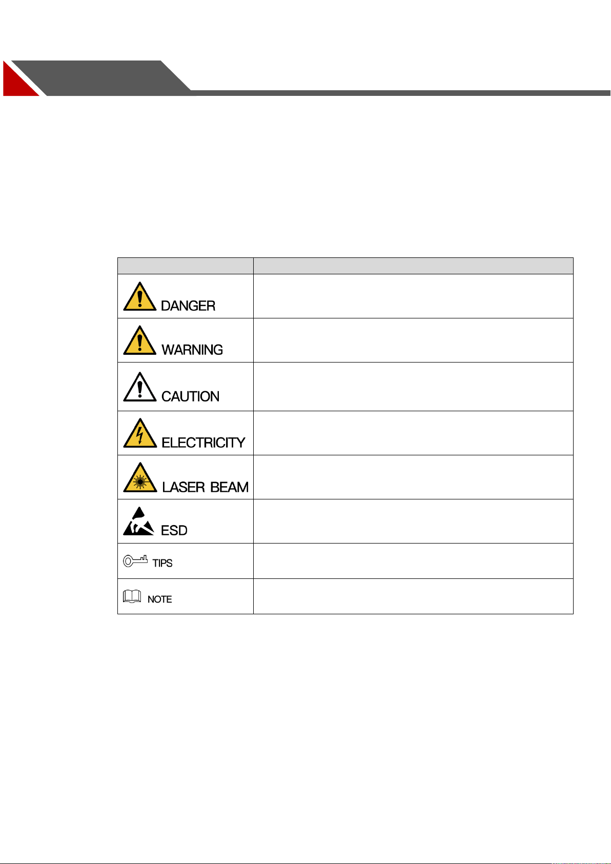
Signal Words
Meaning
Indicates a high potential hazard which, if not avoided, will result
in death or serious injury.
Indicates a medium or low potential hazard which, if not avoided,
could result in slight or moderate injury.
Indicates a potential risk which, if not avoided, could result in
property damage, data loss, lower performance, or unpredictable
result.
Indicates dangerous high voltage.
Take care to avoid coming into contact with electricity.
Indicates a laser radiation hazard.
Take care to avoid exposure to a laser beam.
Electrostatic Sensitive Devices.
Indicates a device that is sensitive to electrostatic discharge.
Provides methods to help you solve a problem or save you time.
Provides additional information as the emphasis and supplement
to the text.
This user’s manual (hereinafter referred to be "the Manual") introduces the functions and
operations of the Network Video Recorder (NVR) devices (hereinafter referred to be "the
Device").
Safety Instructions
The following categorized signal words with defined meaning might appear in the Manual.
Foreword
Privacy Protection Notice
As the device user or data controller, you might collect personal data of others' such as face,
fingerprints, car plate number, Email address, phone number, GPS and so on. You need to be in
compliance with the local privacy protection laws and regulations to protect the legitimate rights
and interests of other people by implementing measures include but not limited to: providing
clear and visible identification to inform data subject the existence of surveillance area and
providing related contact.
About the Manual
IX
Page 11

The Manual is for reference only. If there is inconsistency between the Manual and the
actual product, the actual product shall govern.
We are not liable for any loss caused by the operations that do not comply with the Manual.
The Manual would be updated according to the latest laws and regulations of related
regions. For detailed information, see the paper User's Manual, CD-ROM, QR code or our
official website. If there is inconsistency between paper User's Manual and the electronic
version, the electronic version shall prevail.
All the designs and software are subject to change without prior written notice. The product
updates might cause some differences between the actual product and the Manual. Please
contact the customer service for the latest program and supplementary documentation.
There still might be deviation in technical data, functions and operations description, or
errors in print. If there is any doubt or dispute, please refer to our final explanation.
Upgrade the reader software or try other mainstream reader software if the Manual (in PDF
format) cannot be opened.
All trademarks, registered trademarks and the company names in the Manual are the
properties of their respective owners.
Please visit our website, contact the supplier or customer service if there is any problem
occurred when using the device.
If there is any uncertainty or controversy, please refer to our final explanation
X
Page 12

Important Safeguards and Warnings
The following description is the correct application method of the device. Read the manual
carefully before use to prevent danger and property loss. Strictly conform to the manual during
application and keep it properly after reading.
Operating Requirement
Don’t place and install the device in an area exposed to direct sunlight or near heat
generating device.
Don’t install the device in a humid, dusty or fuliginous area.
Keep its horizontal installation, or install it at stable places, and prevent it from falling.
Don’t drip or splash liquids onto the device; don’t put on the device anything filled with
liquids, in order to prevent liquids from flowing into the device.
Install the device at well-ventilated places; don’t block its ventilation opening.
Use the device only within rated input and output range.
Don’t dismantle the device arbitrarily.
Transport, use and store the device within allowed humidity and temperature range.
Power Requirement
Make sure to use batteries according to requirements; otherwise, it may result in fire,
explosion or burning risks of batteries!
To replace batteries, only the same type of batteries can be used.
The product shall use electric wires (power wires) recommended by this area, which shall
be used within its rated specification.
Make sure to use standard power adapter matched with this device. Otherwise, the user
shall undertake resulting personnel injuries or device damages.
Use power supply that meets SELV (safety extra low voltage) requirements, and supply
power with rated voltage that conforms to Limited Power Source in IEC60950-1. For
specific power supply requirements, please refer to device labels.
Products with category I structure shall be connected to grid power output socket, which is
equipped with protective grounding.
Appliance coupler is a disconnecting device. During normal use, please keep an angle that
facilitates operation.
XI
Page 13

1 Features and Specifications
Cloud
Upgrade
For the NVR connected with the Internet, it supports online upgrade to
update applications.
Real-time
Surveillance
VGA, HDMI port. Connect to monitor to realize real-time surveillance.
Some series support TV/VGA/HDMI output at the same time.
Short-cut menu when preview.
Support popular PTZ decoder control protocols. Support preset, tour
and pattern.
Playback
Support each channel real-time record independently, and at the same
time it can support search, forward play, network monitor, record search,
download and etc.
Support various playback modes: slow play, fast play, backward play
and frame by frame play.
Support time title overlay so that you can view event accurate occurred
time
Support specified zone enlargement.
User
Management
Each group has different management powers that can be edited freely.
Every user belongs to an exclusive group.
Storage
Via corresponding setup (such as alarm setup and schedule setup), you
can backup related audio/video data in the network video recorder.
Support Web record and record local video and storage the file in the
client end.
Alarm
Respond to external alarm simultaneously (within 200MS), based on
user’s pre-defined relay setup, system can process the alarm input
correctly and prompt user by screen and voice (support pre-recorded
audio).
Support central alarm server setup, so that alarm information can
remotely notify user automatically. Alarm input can be derived from
1.1 Overview
This series NVR is a high performance network video recorder. This series product support local preview,
multiple-window display, recorded file local storage, remote control and mouse shortcut menu operation,
and remote management and control function.
This series product supports center storage, front-end storage and client-end storage. The monitor zone
in the front-end can be set in anywhere. Working with other front-end devices such as IPC, NVS, this
series product can establish a strong surveillance network via the CMS. In the network system, there is
only one network cable from the monitor center to the monitor zone in the whole network. There is no
audio/video cable from the monitor center to the monitor zone. The whole project is featuring of simple
connection, low-cost, low maintenance work.
This series NVR can be widely used in many areas such as public security, water conservancy,
transportation and education.
1.2 Features
1
Page 14

various connected peripheral devices.
Alert you via email/sms.
Network
Monitor
Through network, sending audio/video data compressed by IPC or NVS
to client-ends, then the data will be decompressed and display.
Support max 128 connections at the same time.
Transmit audio/video data by HTTP, TCP, UDP, MULTICAST,
RTP/RTCP and etc.
Transmit some alarm data or alarm info by SNMP.
Support WEB access in WAN/LAN.
Window Split
Adopt the video compression and digital process to show several
windows in one monitor. Support 1/4/8/9/16/ 25/36-window display when
preview and 1/4/9/16-window display when playback.
Record
Support normal/motion detect/alarm record function. Save the recorded
files in the HDD, USB device, client-end PC, or network storage server.
You can search or playback the saved files at the local-end or via the
Web/USB device.
Backup
Support network backup, USB2.0 record backup function, the recorded
files can be saved in network storage server, peripheral USB2.0
device, burner and etc.
Network
Management
Supervise NVR configuration and control power via Ethernet.
Support management via WEB.
Peripheral
Equipment
Management
Support peripheral equipment management such as protocol setup and
port connection.
Support transparent data transmission such as RS232 (RS-422), RS485
(RS-485).
Auxiliary
Support switch between NTSC and PAL.
Support real-time system resources information and running statistics
display.
Support log file.
Local GUI output. Shortcut menu operation via mouse.
IR control function (For some series product only.). Shortcut menu
operation via remote control.
Play the video/audio from the network camera or NVS remotely.
Model
21-S2 Series
21-P-S2 Series
21-8P-S2 Series
System
System
Resources
4/8/16-ch series
product support
4/8/16 HD
connection
respectively. Total
bandwidth supports
80Mbps.
4/8-ch series product support 4/8 HD
connection respectively. Total bandwidth
supports 80Mbps.
OS
Embedded Linux real-time operation system
1.3 Specifications
1.3.1 NVR21-S2/NVR21-P-S2/NVR21-8P-S2 Series
2
Page 15

Model
21-S2 Series
21-P-S2 Series
21-8P-S2 Series
Operation
Interface
WEB/Local GUI
Decode
Video Decode
Type
H.264
Decode
Capability
Max 4-ch 1080P 30fps or 8-ch 720P 30fps or 8-ch D1 30fps
Video
Video Input
4/8/16-ch network
compression video
input
4/8-ch network compression video input
Video Output
1-channel VGA analog video output
HDMI
1-ch HDMI output. Version number is 1.4
Window Split
1/4/8/9/16-window
1/4/8/9-window
Audio
Audio Input
1-ch bidirectional talk input
Audio Output
1-ch bidirectional talk output
Audio
Compression
Standard
G.711a
Alarm
Alarm Input
N/A
Alarm Output
N/A
Function
Storage
1 built-in SATA port
Multiple-Chann
el Playback
Max 8-channel D1 or 8-channel 720P or 4-channel 1080P playback
3
Page 16

Model
21-S2 Series
21-P-S2 Series
21-8P-S2 Series
Port and
Indicator
RS232 Port
N/A
RS485 Port
N/A
USB Port
2 peripheral USB2.0 ports.
Network
Connection
1 RJ45 10/100Mbps self-adaptive Ethernet port.
PoE
N/A
4
8
Power Port
1 power socket.
Power adapter
power supplying
mode. DC 12V
power.
1 power socket.
Power adapter
power supplying
mode. DC 48V
power.
1 power socket.
Power adapter
power supplying
mode. DC 48V
power.
Power Button
N/A
Power On-off
Button
N/A
IR Receiver
Window
N/A
Clock
Built-in clock.
Indicator Light
One power status indicator light.
One network status indicator light.
One HDD status indicator light.
General
Power
Consumption
<10W (No HDD)
Working
Temperature
﹣10℃~﹢55℃
Working
Humidity
10℅~90℅
Air pressure
86kPa~106kPa
Dimension
205mm×206.75mm×
205mm×206.75mm×
425mm×95mm×260
4
Page 17

Model
21-S2 Series
21-P-S2 Series
21-8P-S2 Series
45.2mm
45.2mm
mm
Weight
0.5kg~2kg (No HDD)
Installation
Mode
Desk installation
Model
NVR1A-4P Series
NVR1A-8P Series
System
System
Resources
4/8-ch series product support 4/8 HD connection respectively. Total
bandwidth supports 80Mbps.
OS
Embedded Linux real-time operation system
Operation
Interface
WEB/Local GUI
Decode
Video Decode
Type
Smart H.264+/H.264
Decode
Capability
Max 4-ch 1080P 30fps or 8-ch 720P 30fps or 8-ch D1 30fps
Video
Video Input
4/8-ch network compression video input
Video Output
1-channel VGA analog video output
HDMI
1-ch HDMI output. Version number is 1.4
Window Split
1/4/8/9-window
Audio
Audio Input
1-ch bidirectional talk input
Audio Output
1-ch bidirectional talk output
1.3.2 NVR1A-4P/1A-8P Series
5
Page 18

Model
NVR1A-4P Series
NVR1A-8P Series
Audio
Compression
Standard
G.711a
Alarm
Alarm Input
N/A
Alarm Output
N/A
Function
Storage
1 built-in SATA port
Multiple-Chann
el Playback
Max 8-channel D1 or 8-channel 720P or 4-channel 1080P playback
Port and
Indicator
RS232 Port
N/A
RS485 Port
N/A
USB Port
2 peripheral USB2.0 ports.
Network
Connection
1 RJ45 10/100Mbps self-adaptive Ethernet port.
PoE
4
8
Power Port
1 power socket. Power adapter
power supplying mode. DC 48V
power.
1 power socket. Power adapter
power supplying mode. DC 48V
power.
Power Button
N/A
Power On-off
Button
N/A
IR Receiver
Window
N/A
Clock
Built-in clock.
6
Page 19

Model
NVR1A-4P Series
NVR1A-8P Series
Indicator Light
One power status indicator light.
One network status indicator light.
One HDD status indicator light.
General
Power
Consumption
<10W (No HDD)
Working
Temperature
﹣10℃~﹢55℃
Working
Humidity
10℅~90℅
Air pressure
86kPa~106kPa
Dimension
205mm×206.75mm×45.2mm
425mm×95mm×260mm
Weight
0.5kg~2kg (No HDD)
Installation
Mode
Desk installation
Model
NVR21HS-S2
Series
NVR21HS-P-S2
Series
NVR21HS-8P-S2
Series
System
System
Resources
4/8/16-ch series
product support
4/8/16 HD
connection
respectively. Total
bandwidth supports
80Mbps.
4/8-ch series product support 4/8 HD
connection respectively. Total bandwidth
supports 80Mbps.
OS
Embedded Linux real-time operation system
Operation
Interface
WEB/Local GUI
Decode
Video Decode
Type
H.264
Decode
Capability
Max 4-ch 1080P 30fps or 8-ch 720P 30fs or 8-ch D1 30fps
Video
Video Input
4/8/16-ch network
compression video
input
4/8-ch network compression video input
1.3.3 NVR21HS-S2/21HS-P-S2/21HS-8P-S2 Series
7
Page 20

Model
NVR21HS-S2
Series
NVR21HS-P-S2
Series
NVR21HS-8P-S2
Series
Video Output
1-channel VGA analog video output
HDMI
1-ch HDMI output. Version number is 1.4
Window Split
1/4/8/9/16-window
1/4/8/9-window
Audio
Audio Input
1-ch bidirectional talk input
Audio Output
1-ch bidirectional talk output
Audio
Compression
Standard
G.711a
Alarm
Alarm Input
N/A
Alarm Output
N/A
Function
Storage
1 built-in SATA port
Multiple-Chann
el Playback
Max 4-channel 1080P or 8-channel 720P or 8-channel D1 playback
Port and
Indicator
RS232 Port
N/A
RS485 Port
N/A
USB Port
2 peripheral USB2.0 ports.
Network
Connection
1 RJ45 10/100Mbps self-adaptive Ethernet port.
PoE Port
N/A
4
8
Power Port
1 power socket.
Power adapter
power supplying
mode. DC 12V
power.
1 power socket.
Power adapter
power supplying
mode. DC 48V
power.
1 power socket.
Power adapter
power supplying
mode. DC 48V
power.
Power Button
N/A
Power On-off
Button
N/A
IR Receiver
Window
N/A
Clock
Built-in clock.
Indicator Light
One power status indicator light.
One network status indicator light.
8
Page 21

Model
NVR21HS-S2
Series
NVR21HS-P-S2
Series
NVR21HS-8P-S2
Series
One HDD status indicator light.
General
Power
Consumption
<10W (No HDD)
Working
Temperature
﹣10℃~﹢55℃
Working
Humidity
10℅~90℅
Air pressure
86kPa~106kPa
Dimension(W×
D×H)
260mm×220mm×44mm
Weight
0.7kg~0.8kg (No HDD)
Installation
Mode
Desk installation
Model
NVR1AHS Series
NVR1AHS-4P
Series
NVR1AHS-8P
Series
System
System
Resources
4/8-ch series product
support 4/8 HD
connection
respectively. Total
bandwidth supports
80Mbps.
4/8-ch series product support 4/8 HD
connection respectively. Total bandwidth
supports 80Mbps.
OS
Embedded Linux real-time operation system
Operation
Interface
WEB/Local GUI
Decode
Video Decode
Type
Smart H.264+/H.264
Decode
Capability
Max 4-ch 1080P 30fps or 8-ch 720P 30fs or 8-ch D1 30fps
Video
Video Input
4/8-ch network
compression video
input
4/8-ch network compression video input
Video Output
1-channel VGA analog video output
HDMI
1-ch HDMI output. Version number is 1.4
Window Split
1/4/8/9-window
1/4/8/9-window
1.3.4 NVR1AHS/1AHS-4P/1AHS-8P Series
9
Page 22

Model
NVR1AHS Series
NVR1AHS-4P
Series
NVR1AHS-8P
Series
Audio
Audio Input
1-ch bidirectional talk input
Audio Output
1-ch bidirectional talk output
Audio
Compression
Standard
G.711a
Alarm
Alarm Input
N/A
Alarm Output
N/A
Function
Storage
1 built-in SATA port
Multiple-Chann
el Playback
Max 4-channel 1080P or 8-channel 720P or 8-channel D1 playback
Port and
Indicator
RS232 Port
N/A
RS485 Port
N/A
USB Port
2 peripheral USB2.0 ports.
Network
Connection
1 RJ45 10/100Mbps self-adaptive Ethernet port.
PoE Port
N/A
4
8
Power Port
1 power socket.
Power adapter
power supplying
mode. DC 12V
power.
1 power socket.
Power adapter
power supplying
mode. DC 48V
power.
1 power socket.
Power adapter
power supplying
mode. DC 48V
power.
Power Button
N/A
Power On-off
Button
N/A
IR Receiver
Window
N/A
Clock
Built-in clock.
Indicator Light
One power status indicator light.
One network status indicator light.
One HDD status indicator light.
General
Power
Consumption
<10W (No HDD)
Working
Temperature
﹣10℃~﹢55℃
10
Page 23

Model
NVR1AHS Series
NVR1AHS-4P
Series
NVR1AHS-8P
Series
Working
Humidity
10℅~90℅
Air pressure
86kPa~106kPa
Dimension(W×
D×H)
260mm×220mm×44mm
Weight
0.7kg~0.8kg (No HDD)
Installation
Mode
Desk installation
Model
41HS-W-S2 Series
System
System
Resources
4/8-ch series product support 4/8 HD connection respectively. Total
bandwidth supports 80Mbps.
OS
Embedded Linux real-time operation system
Operation
Interface
WEB/Local GUI
Decode
Video Decode
Type
H.264/MJPEG/MPEG4
Decode
Capability
Max 8-ch 1080P or 4-ch 3M or 2-ch 5M.
Video
Video Input
4/8-ch network compression video input
Video Output
1-channel VGA analog video output
HDMI
1-ch HDMI output. Version number is 1.4
Window Split
1/4/8/9-window
Audio
Audio Input
N/A
Audio Output
N/A
Audio
Compression
Standard
G.711a
Alarm
Alarm Input
N/A
Alarm Output
N/A
Function
Storage
1 built-in SATA port
1.3.5 NVR41HS-W-S2 Series
11
Page 24

Model
41HS-W-S2 Series
Multiple-Chann
el Playback
Max 8-ch 1080P playback
Port and
Indicator
RS232 Port
N/A
RS485 Port
N/A
USB Port
2 peripheral USB2.0 ports. One at the front panel and one at the rear
panel.
Network
Connection
1 RJ45 10/100Mbps self-adaptive Ethernet port.
PoE Port
N/A
Power Port
1 power socket. Power adapter power supplying mode. DC 12V/2A
power.
Power Button
N/A
Power On-off
Button
N/A
IR Receiver
Window
N/A
Clock
Built-in clock.
Indicator Light
One power status indicator light.
One network status indicator light.
One HDD status indicator light.
General
Power
Consumption
<30W (No HDD)
Working
Temperature
﹣10℃~﹢55℃
Working
Humidity
10℅~90℅
Air pressure
86kPa~106kPa
Dimension(W*
D*H)
375mm×287mm×52mm
Weight
1.5kg~2.5kg(No HDD)
Installation
Mode
Desk installation
Model
41 Series
41-P Series
41-8P Series
41-W Series
System
System
Resources
4/8/16-ch series product support 4/8/16 HD connection respectively.
Total bandwidth supports 28/56/80Mbps respectively.
OS
Embedded Linux real-time operation system
1.3.6 NVR41/41-P/41-8P/41-W Series
12
Page 25

Model
41 Series
41-P Series
41-8P Series
41-W Series
Operation
Interface
WEB/Local GUI
Decode
Video Decode
Type
H.264/MJPEG/MJPEG4
Decode
Capability
Max 2-ch 5M 25fps or 4-ch 3M 25fps or 4-ch 1080P 30fps
or 8-ch 720P 30fs
Video
Video Input
4/8/16-ch network compression video input
Video Output
1-channel VGA analog video output
HDMI
1-ch HDMI output. Version number is 1.4
Window Split
1/4/8/9/16-window
1/4-window
Audio
Audio Input
1-ch bidirectional talk input
Audio Output
1-ch bidirectional talk output
Audio
Compression
Standard
G.711a
Alarm
Alarm Input
N/A
Alarm Output
N/A
Function
Storage
1 built-in SATA port
Multiple-Chann
el Playback
Max 4-channel 1080P playback
WIFI AP
N/A
Yes
Port and
Indicator
RS232 Port
N/A
RS485 Port
N/A
USB Port
2 peripheral USB2.0 ports.
Network
Connection
1 RJ45 10/100Mbps self-adaptive Ethernet port.
PoE Port
N/A
4 8 N/A
Power Port
1 power
socket. Power
adapter power
supplying
mode. DC 12V
power.
1 power socket. Power adapter
power supplying mode. DC 48V
power.
1 power
socket. Power
adapter power
supplying
mode. DC 12V
power.
13
Page 26

Model
41 Series
41-P Series
41-8P Series
41-W Series
Power Button
1 button
Power On-off
Button
N/A
IR Receiver
Window
N/A
Clock
Built-in clock.
Indicator Light
One power status indicator light.
One network status indicator light.
One HDD status indicator light.
General
Power
Consumption
<10W (No HDD)
Working
Temperature
﹣10℃~﹢55℃
Working
Humidity
10℅~90℅
Air pressure
86kPa~106kPa
Dimension
205mm×206.75mm×45.2mm
270mm×204m
m×42mm
205mm×206.7
5mm×45.2mm
Weight
0.5kg~1kg (No HDD)
Installation
Mode
Desk installation
Model
41H Series
41H-P Series
41H-8P Series
System
System
Resources
4/8/16-ch series product support 4/8/16 HD connection respectively.
Total bandwidth supports 28/56/80Mbps respectively.
OS
Embedded Linux real-time operation system
Operation
Interface
WEB/Local GUI
Decode
Video Decode
Type
H.264/MJPEG/MJPEG4
Decode
Capability
Max 2-ch 5M 25fps or 4-ch 3M 25fps or 4-ch 1080P 30fps
or 8-ch 720P 30fs
Video
Video Input
4/8/16-ch network compression video input
Video Output
1-channel VGA analog video output
HDMI
1-ch HDMI output. Version number is 1.4
Window Split
1/4/8/9/16-window
1.3.7 NVR41H/41H-P/41H-8P Series
14
Page 27

Model
41H Series
41H-P Series
41H-8P Series
Audio
Audio Input
1-ch bidirectional talk input
Audio Output
1-ch bidirectional talk output
Audio
Compression
Standard
G.711a
Alarm
Alarm Input
N/A
2-channel
Alarm Output
N/A
2-channel
Function
Storage
1 built-in SATA port
Multiple-Chann
el Playback
Max 4-channel 1080P playback
Port and
Indicator
RS232 Port
N/A
RS485 Port
N/A
USB Port
2 peripheral USB2.0 ports.
Network
Connection
1 RJ45 10/100Mbps self-adaptive Ethernet port.
PoE Port
N/A
4
8
Power Port
1 power socket.
Power adapter
power supplying
mode. DC 12V
power.
1 power socket. Power adapter power
supplying mode. DC 48V power.
Power Button
1 button
Power On-off
Button
N/A
IR Receiver
Window
N/A
Clock
Built-in clock.
Indicator Light
One power status indicator light.
One network status indicator light.
One HDD status indicator light.
General
Power
Consumption
<10W (No HDD)
Working
Temperature
﹣10℃~﹢55℃
Working
Humidity
10℅~90℅
15
Page 28

Model
41H Series
41H-P Series
41H-8P Series
Air pressure
86kPa~106kPa
Dimension
325mm×250.58mm×51mm
Weight
0.5kg~1kg (No HDD)
Installation
Mode
Desk installation
Model
NVR22-S2 Series
NVR22-P-S2 Series
NVR22-8P-S2
Series
System
System
Resources
4/8/16-ch series
product support
4/8/16 HD
connection
respectively. Total
bandwidth supports
80Mbps.
4/8-ch series product support 4/8 HD
connection respectively. Total bandwidth
supports 80Mbps.
OS
Embedded Linux real-time operation system
Operation
Interface
WEB/Local GUI
Decode
Video Decode
Type
H.264
Decode
Capability
Max 4-ch 1080P 30fps or 8-ch 720P 30fs or 8-ch D1 30fps
Video
Video Input
4/8/16-ch network
compression video
input
4/8-ch network compression video input
Video Output
1-channel VGA analog video output
HDMI
1-ch HDMI output. Version number is 1.4
Window Split
1/4/8/9/16-window
1/4/8/9-window
Audio
Audio Input
1-ch bidirectional talk input
Audio Output
1-ch bidirectional talk output
Audio
Compression
Standard
G.711a
Alarm
Alarm Input
N/A
1.3.8 NVR22-S2/22-P-S2/22-8P-S2 Series
16
Page 29

Model
NVR22-S2 Series
NVR22-P-S2 Series
NVR22-8P-S2
Series
Alarm Output
N/A
Function
Storage
2 built-in SATA ports
Multiple-Chann
el Playback
Max 4-channel 1080P or 8-channel 720P or 8-channel D1 playback
Port and
Indicator
RS232 Port
N/A
RS485 Port
N/A
USB Port
2 peripheral USB2.0 ports.
Network
Connection
1 RJ45 10/100Mbps self-adaptive Ethernet port.
PoE Port
N/A
4
8
Power Port
1 power socket.
Power adapter
power supplying
mode. DC 12V
power.
1 power socket.
Power adapter
power supplying
mode. DC 48V
power.
1 power socket.
Power adapter
power supplying
mode. DC 48V
power.
Power Button
N/A
Power On-off
Button
N/A
IR Receiver
Window
N/A
Clock
Built-in clock.
Indicator Light
One power status indicator light.
One network status indicator light.
One HDD status indicator light.
General
Power
Consumption
<10W (No HDD)
Working
Temperature
﹣10℃~﹢55℃
Working
Humidity
10℅~90℅
Air pressure
86kPa~106kPa
Dimension(W×
D×H)
375mm×287mm×52mm
Weight
1.5kg~2.5kg (No HDD)
Installation
Desk installation
17
Page 30

Model
NVR22-S2 Series
NVR22-P-S2 Series
NVR22-8P-S2
Series
Mode
Model
42N Series
System
System
Resource
s
4/8/16/32-channel series product support 4/8/16/32-channel HD connection
respectively. Main stream bandwidth supports 40/80/160/160Mbps
respectively.
Operation
System
Embedded Linux real-time operation system
Operation
Interface
WEB/Local GUI
Decode
Video
Compres
sion
H.264/MJPEG/MPEG4
Decode
Capacity
Max supports 16-channel D1, or 8-channel 720P, or 4-channel 1080P, or
4*3M or 2*5M decode.
Video
Video
Input
4/8/16/32-ch network compression video input
Video
Output
1-channel VGA analog video output.
HDMI
1-ch HDMI output. Version number is 1.4
Window
Split
1/4/8/9/16-window
Audio
Audio
Input
1-ch bidirectional talk input
Audio
Output
1-ch bidirectional talk output
Audio
Compres
sion
G.711a
Alarm
Alarm
Input
N/A
Alarm
Output
N/A
Function
Storage
2 built-in SATA ports.
Multiple-c
hannel
Playback
Max 8-channel 720P/4-channel 1080P playback at the same time.
Port and
Indicator
RS232
Port
One RS232 port to debug transparent COM data.
1.3.9 NVR42N Series
18
Page 31

RS485
port
One RS485 port to control PTZ. Support various protocols.
USB2.0
Port
Three peripheral USB2.0 ports.
Network
Connecti
on
1 RJ45 10/100/1000Mbps self-adaptive Ethernet port.
Power
Port
One power port, power adapter. Input DC 12V.
Power
Button
One button. At the rear panel.
Power
On-off
Button
One button. At the front-panel.
IR
Receiver
Window
Support IR remote control
Clock
Built-in clock.
Indicator
Light
One power status indicator light.
One network status indicator light.
One HDD status indicator light.
General
Power
Consump
tion
<30W(No HDD)
Working
Temperat
ure
-10℃~+55℃
Working
Humidity
10℅-90℅
Air
pressure
86kpa-106kpa
Dimensio
n
375mm×287mm×52mm
Weight
1.5kg~2.5kg(No HDD)
Installatio
n
Desk installation
Model
42 Series
42-P Series
42-8P Series
System
System
Resource
s
4/8/16/32-channel series product support 4/8/16/32-channel HD connection
respectively. Main stream bandwidth supports 40/80/160/160Mbps
respectively.
1.3.10 NVR42/42-P/42-8P Series
19
Page 32

Operation
System
Embedded Linux real-time operation system
Operation
Interface
WEB/Local GUI
Decode
Video
Compres
sion
H.264/MJPEG/MPEG4
Decode
Capacity
Max supports 16-channel D1, or 8-channel 720P, or 4-channel 1080P, or
4*3M or 2*5M decode.
Video
Video
Input
4/8/16/32-ch network compression video input
Video
Output
1-channel VGA analog video output.
HDMI
1-ch HDMI output. Version number is 1.4
Window
Split
1/4/8/9/16-window
Audio
Audio
Input
1-ch bidirectional talk input
Audio
Output
1-ch bidirectional talk output
Audio
Compres
sion
G.711a
Alarm
Alarm
Input
4-ch alarm input
Alarm
Output
2-ch alarm output
Function
Storage
2 built-in SATA ports.
Multiple-c
hannel
Playback
Max 8-channel 720P/4-channel 1080P playback at the same time.
Port and
Indicator
RS232
Port
One RS232 port to debug transparent COM data.
RS485
port
One RS485 port to control PTZ. Support various protocols.
USB2.0
Port
Three peripheral USB2.0 ports.
Network
Connecti
on
1 RJ45 10/100/1000Mbps self-adaptive Ethernet port.
Power
Port
One power port,
power adapter. Input
DC 12V.
Two power ports. Input
DC 12V/DC 48V.
One power ports.
Input 100-240V ,
47~63Hz.
20
Page 33

Power
Button
One button. At the rear panel.
Power
On-off
Button
One button. At the front-panel.
IR
Receiver
Window
Support IR remote control
Clock
Built-in clock.
Indicator
Light
One power status indicator light.
One network status indicator light.
One HDD status indicator light.
General
Power
Consump
tion
<30W(No HDD)
Working
Temperat
ure
-10℃~+55℃
Working
Humidity
10℅-90℅
Air
pressure
86kpa-106kpa
Dimensio
n
375mm×287mm×52m
m
375mm×287mm×52mm
295mm×275mm×47m
m
Weight
1.5kg~2.5kg(No HDD)
Installatio
n
Desk installation
Model
42-16P Series
System
System
Resource
s
16/32-channel series product support 4/8/16/32-channel HD connection
respectively. Main stream/sub stream bandwidth supports 200Mbps.
Operation
System
Embedded Linux real-time operation system
Operation
Interface
WEB/Local GUI
Decode
Video
Compres
sion
H.264/MJPEG/MPEG4
Decode
Capacity
Max supports 32-channel D1, or 16-channel 720P, or 8-channel 1080P, or
4*3M or 2*5M decode.
1.3.11 NVR42-16P Series
21
Page 34

Video
Video
Input
4/8/16/32-ch network compression video input
Video
Output
1-channel VGA analog video output.
HDMI
1-ch HDMI output. Version number is 1.4
Window
Split
1/4/8/9/16-window
Audio
Audio
Input
1-ch bidirectional talk input
Audio
Output
1-ch bidirectional talk output
Audio
Compres
sion
G.711a
Alarm
Alarm
Input
4-ch alarm input
Alarm
Output
2-ch alarm output
Function
Storage
2 built-in SATA ports.
Multiple-c
hannel
Playback
Max 16-channel 720P/8-channel 1080P playback at the same time.
Port and
Indicator
RS232
Port
One RS232 port to debug transparent COM data.
RS485
port
One RS485 port to control PTZ. Support various protocols.
USB2.0
Port
One peripheral USB2.0 port.
One peripheral USB3.0 port.
Network
Connecti
on
1 RJ45 10/100/1000Mbps self-adaptive Ethernet port.
Power
Port
One power ports. Input 100-240V,47~63Hz.
Power
Button
One button. At the rear panel.
Power
On-off
Button
N/A
IR
Receiver
Window
N/A
Clock
Built-in clock.
Indicator
One power status indicator light.
22
Page 35

Light
One network status indicator light.
One HDD status indicator light.
General
Power
Consump
tion
<30W(No HDD)
Working
Temperat
ure
-10℃~+55℃
Working
Humidity
10℅-90℅
Air
pressure
86kpa-106kpa
Dimensio
n
375mm×287mm×52mm
Weight
1.5kg~2.5kg(No HDD)
Installatio
n
Desk installation
Model
NVR2A16 Series
System
System
Resources
16-ch series product support 16 HD connection respectively. Total
bandwidth supports 80Mbps.
OS
Embedded Linux real-time operation system
Operation
Interface
WEB/Local GUI
Decode
Video Decode
Type
Smart H.264+/H.264
Decode
Capability
Max 4-ch 1080P 30fps or 8-ch 720P 30fs or 8-ch D1 30fps
Video
Video Input
16-ch network compression video input
Video Output
1-channel VGA analog video output
HDMI
1-ch HDMI output. Version number is 1.4
Window Split
1/4/8/9/16-window
Audio
Audio Input
1-ch bidirectional talk input
Audio Output
1-ch bidirectional talk output
Audio
Compression
Standard
G.711a
1.3.12 NVR2A16 Series
23
Page 36

Model
NVR2A16 Series
Alarm
Alarm Input
N/A
Alarm Output
N/A
Function
Storage
2 built-in SATA ports
Multiple-Chann
el Playback
Max 4-channel 1080P or 8-channel 720P or 8-channel D1 playback
Port and
Indicator
RS232 Port
N/A
RS485 Port
N/A
USB Port
2 peripheral USB2.0 ports.
Network
Connection
1 RJ45 10/100Mbps self-adaptive Ethernet port.
PoE Port
N/A
Power Port
1 power socket. Power adapter power supplying mode. DC 12V
power.
Power Button
N/A
Power On-off
Button
N/A
IR Receiver
Window
N/A
Clock
Built-in clock.
Indicator Light
One power status indicator light.
One network status indicator light.
One HDD status indicator light.
General
Power
Consumption
<10W (No HDD)
Working
Temperature
﹣10℃~﹢55℃
Working
Humidity
10℅~90℅
Air pressure
86kPa~106kPa
Dimension(W×
D×H)
375mm×287mm×52mm
Weight
1.5kg~2.5kg (No HDD)
Installation
Mode
Desk installation
Model
NVR52-4KS2/52-8P-4KS2/52-16P-4KS2 Series
1.3.13 NVR52-4KS2/52-8P-4KS2/52-16P-4KS2 Series
24
Page 37

System
System
Resource
s
8/16/32-channel series product support 8/16/32-channel HD connection
respectively. The main stream bandwidth supports 80/160/320Mbps.
Operation
System
Embedded Linux real-time operation system
Operation
Interface
WEB/Local GUI
Decode
Video
Compres
sion
MPEG4, MJPEG, H.264, H.265
Decode
Capacity
H.264/H.265: Max supports 64-channel D1, or 32-channel 720P,
16-channel 1080P or 4-channel 4K decode.
Video
Video
Input
8/16/32-ch network compression video input
Video
Output
1-channel VGA analog video output.
HDMI
1-ch HDMI output. Version number is 2.0
Window
Split
1/4/8/9/16/25/36-window
Audio
Audio
Input
1-ch bidirectional talk input
Audio
Output
1-ch bidirectional talk output
Audio
Compres
sion
G.711a, G.711u, PCM, G.726 (The bidirectional talk function supports
G.711a, G.711u, PCM only.)
Alarm
Alarm
Input
4-ch alarm input
Alarm
Output
2-ch relay output
Function
Storage
2 built-in SATA ports.
Multiple-c
hannel
Playback
Max 64-channel D1/32-channel 720P/16-channel 1080P/4-channel 4K
playback at the same time.
Record
Mode
Overwrite
Backup
Mode
Flash disk, DVD burner.
Port and
Indicator
Network
Protocol
IPv4/IPv6/HTTP/UPnP/NTP/SADP/SNMP/PPPoE/DNS/FTP/ONVIF(Versio
n 2.4)/PSIA
RS232
Port
One RS232 port to debug transparent COM data.
25
Page 38

RS485
port
One RS485 port to control PTZ. Support various protocols.
USB Port
2 peripheral USB ports: One USB2.0 at the front panel and one USB3.0 at
the rear panel.
Network
Connecti
on
One RJ45 10/100/1000Mbps self-adaptive Ethernet port.
Power
Port
One power socket. Power adapter power supplying. Input DC 12V-4A
power.
Power
Button
One button. At the rear panel.
Power
On-off
Button
N/A
IR
Receiver
Window
N/A
General
Indicator
Light
One power status indicator light.
One network status indicator light.
One HDD status indicator light.
One device running status indicator light.
Power
DC 12V
Power
Consump
tion
General series: 9.5W(No HDD)
8 PoE series: 14.5W(No HDD)
16 PoE series: 15.2W(No HDD)
Working
Temperat
ure
-10℃~+55℃
Working
Humidity
10℅-90℅
Air
pressure
86kpa-106kpa
Dimensio
n
General series: 375mm(W) × 56mm(H) × 281.4mm(D)
PoE series: 375mm(W) × 53mm(H) × 327.3mm(D)
Weight
(No HDD)
General series: : 1.60Kg
8 PoE series: 2.60Kg
16 PoE series: 2.70Kg
Installatio
n
Desk/rack installation
Model
NVR44 Series
NVR44-8P Series
NVR44-16P Series
1.3.14 NVR44/44-8P/44-16P Series
26
Page 39

System
System
Resource
s
8/16/32-channel series product support 8/16/32-channel HD connection
respectively. The main stream bandwidth supports 200Mbps.
Operation
System
Embedded Linux real-time operation system
Operation
Interface
WEB/Local GUI
Decode
Video
Compres
sion
H.264/MJPEG/MPEG4
Decode
Capacity
Max supports 16-channel D1, or 8-channel 720P, or 4-channel 3M or 2*5M
decode.
Video
Video
Input
8/16/32-ch network compression video input
Video
Output
1-channel VGA analog video output.
HDMI
1-ch HDMI output. Version number is 1.4
Window
Split
1/4/8/9/16-window
Audio
Audio
Input
1-ch bidirectional talk input
Audio
Output
1-ch bidirectional talk output
Audio
Compres
sion
G.711a
Alarm
Alarm
Input
16-ch alarm input
Alarm
Output
4-ch alarm output
Relay output. Relay (DC 30V /1A,AC 125V/0.5A(Activation output))
Including one controllable DC +12V output.
Function
Storage
4 built-in SATA ports. 1 external eSATA port.
Multiple-c
hannel
Playback
Max 8-channel 720P/4-channel 1080P playback at the same time.
Port and
Indicator
RS232
Port
One RS232 port to debug transparent COM data.
RS485
port
One RS485 port to control PTZ. Support various protocols.
USB2.0
Port
2 peripheral USB2.0 ports. One at the front panel and one at the rear panel.
Network
Connecti
on
One RJ45 10/100/1000Mbps self-adaptive Ethernet port.
27
Page 40

Power
Port
One power port. Input 100-240V,50~60Hz.
Power
Button
One button. At the rear panel.
Power
On-off
Button
One button. At the front-panel.
IR
Receiver
Window
Support IR remote control
Clock
Built-in clock.
General
Indicator
Light
One power status indicator light.
One network status indicator light.
One HDD status indicator light.
Power
Consump
tion
<30W(No HDD)
Working
Temperat
ure
-10℃~+55℃
Working
Humidity
10℅-90℅
Air
pressure
86kpa-106kpa
Dimensio
n
1.5U, 440mm × 460mm × 68mm
Weight
5kg~6kg(No HDD)
Installatio
n
Desk installation
Specifications
NVR54-4KS2/54-16P-4KS2 Series
System
Main Processor
Industrial embedded micro processor
Operation System
Embedded LINUX system
System
Resources
16/32/64-channel main stream connection: max supports
160/320/320Mbps
User Interface
WEB, local GUI
Audio
Parameters
Audio Input
1-ch MIC bidirectional talk audio input
Audio Output
2-ch MIC bidirectional talk audio output
Audio
Compression
Standard
G.711a, G.711u, PCM, G.726 (The bidirectional talk supports
G.711a, G.711u, PCM only.)
1.3.15 NVR54-4KS2/54-16P-4KS2 Series
28
Page 41

Video
Parameters
Video Input
16/32/64-ch network compression video input
Video Output
2-channel VGA
2-channel HDMI.
Video
Compression
Standard
H.264
Window Split
Mode
1/4/8/9/16/25/36/64-screen.
Alarm
Parameters
Alarm Input
16-channel
Alarm Output
6-channel relay output
Decode
Parameters
Decode Type
MPEG4, MJPEG, H.264, H.265
Decode Capability
H.264/H.265: 64-channel×D1, 32-channel×720P, 16-channel
1080P; 4-channel 4K.
Functions
Record Mode
Manual recording, motion detection recording, schedule
recording and alarm recording.
Priority: Manual recording>card number recording-> alarm
recording>motion detection recording>schedule recording.
Multi-Channel
Playback
Max support 16-channel 1080P playback at the same time.
Motion Detect
Each screen supports 396/330((PAL 22×18, NTSC 22×15)
detection zones. Various sensitivity levels.
Privacy Mask
Each channel supports 4 privacy mask zones.
Record Mode
Overwrite
Backup Mode
Flash disk, eSATA, DVD burner.
Network
Function
Network Protocol
IPv4/IPv6/HTTP/UPnP/NTP/SADP/SNMP/PPPoE/DNS/FTP/
ONVIF(Version 2.4)/PSIA
SATA Port
4 SATA Ports
eSATA Port
1 eSATA port
RS232 Port
1 RS232 port. To debug and transmit COM data.
RS485 Port
1 RS485 port. To control peripheral PTZ and etc. Support
various protocols.
USB Port
1 USB 2.0 port at the front panel and 2 USB3.0 ports at the
rear panel.
HDMI Port
2 HDMI ports
Network Port
2 RJ45 10/100/1000Mbps self-adaptive Ethernet ports
Power Port
One power socket. Power adapter power supplying. Input AC
100V~240V, 50Hz~60Hz.
Power On-off
Button
One at the rear panel.
29
Page 42

Indicator Light
4 indicator lights.
1 system running status indicator light
1 HDD indicator light
1 network status indicator light
1 power status indicator light
General
Parameters
Power
AC90~264V
Power
Consumption
General series: 16.7W(No HDD)
16 PoE series: 17.5W(No HDD)
Working
Temperature
-10℃~55℃
Working Humidity
10%~90%(No condensation)
Dimensions (W×
H×D)
440×76×411mm
Weight(No HDD)
General series:4.30Kg,
PoE series: 4.65Kg,
Installation Mode
Rack/desktop
Specifications
NVR58-4KS2/58-16P-4KS2 Series
System
Main Processor
Industrial embedded micro processor
Operation System
Embedded LINUX system
System
Resources
16/32/64-channel main stream max supports
160/320/320Mbps
User Interface
WEB, local GUI
Audio
Parameters
Audio Input
1-ch MIC bidirectional talk audio input
Audio Output
2-ch MIC bidirectional talk audio output
Audio
Compression
Standard
G.711a, G.711u, PCM, G.726 (The bidirectional talk supports
G.711a, G.711u, PCM only.)
Video
Parameters
Video Input
16/32/64-ch network compression video input
Video Output
2-channel VGA
2-channel HDMI.
Video
Compression
Standard
H.264
Window Split
Mode
1/4/8/9/16/25/36/64-screen.
Alarm
Parameters
Alarm Input
16-channel
Alarm Output
6-channel relay output
Decode
Parameters
Decode Type
MPEG4, MJPEG, H.264, H.265
Decode Capability
H.264/H.265: 64-channel×D1;32-channel×720P, 16-channel
1080P;4-channel 4K
1.3.16 NVR58-4KS2/58-16P-4KS2 Series
30
Page 43

Functions
Record Mode
Manual recording, motion detection recording, schedule
recording and alarm recording.
Priority: Manual recording>card number recording-> alarm
recording>motion detection recording>schedule recording.
Multi-Channel
Playback
Max support 16-channel 1080P playback at the same time.
Motion Detect
Each screen supports 396/330((PAL 22×18, NTSC 22×15)
detection zones. Various sensitivity levels.
Privacy Mask
Each channel supports 4 privacy mask zones.
Record Mode
Overwrite
Backup Mode
Flash disk, eSATA, DVD burner.
Network
Function
Network Protocol
IPv4/IPv6/HTTP/UPnP/NTP/SADP/SNMP/PPPoE/DNS/FTP/
ONVIF(Version 2.4)/PSIA
SATA Port
8 SATA Ports
eSATA Port
1 eSATA port
RS232 Port
1 RS232 port. To debug and transmit COM data.
RS485 Port
1 RS485 port. To control peripheral PTZ and etc. Support
various protocols.
USB Port
2 USB 2.0 ports at the front panel and 2 USB3.0 ports at the
rear panel.
HDMI Port
2 HDMI ports
Network Port
2 RJ45 10/100/1000Mbps self-adaptive Ethernet ports
Power Port
One power socket. Power adapter power supplying. Input AC
100V~240V, 50Hz~60Hz.
Power On-off
Button
One at the rear panel.
Indicator Light
4 indicator lights.
1 system running status indicator light
1 HDD indicator light
1 network status indicator light
1 power status indicator light
General
Parameters
Power
AC90~264V
Power
Consumption
General series: 16.7W(No HDD)
16 PoE series: 17.5W(No HDD)
Working
Temperature
-10℃~55℃
Working Humidity
10%~90%(No condensation)
Dimensions (W×
H×D)
439.7×95×450.8mm
Weight (No HDD)
General series:6.55Kg,
PoE series: 7Kg.
Installation Mode
Rack/desktop
1.3.17 NVR48/48-16P Series
31
Page 44

Model
NVR48 Series
NVR48-16P Series
System
System
Resource
s
8/16/32-channel series product support 8/16/32-channel HD connection
respectively. The main stream bandwidth supports 200Mbps.
Operation
System
Embedded Linux real-time operation system
Operation
Interface
WEB/Local GUI
Decode
Video
Compres
sion
H.264/MJPEG/MPEG4
Decode
Capacity
Max supports 16-channel D1, or 8-channel 720P, or 4-channel 3M or 2*5M
decode.
Video
Video
Input
8/16/32-ch network compression video input
Video
Output
1-channel VGA analog video output.
HDMI
1-ch HDMI output. Version number is 1.4
Window
Split
1/4/8/9/16-window
Audio
Audio
Input
1-ch bidirectional talk input
Audio
Output
1-ch bidirectional talk output
Audio
Compres
sion
G.711a
Alarm
Alarm
Input
16-ch alarm input
Alarm
Output
4-ch alarm output
Relay output. Relay (DC 30V /1A,AC 125V/0.5A(Activation output))
Including one controllable DC +12V output.
Function
Storage
4 built-in SATA ports. 1 external eSATA port.
Multiple-c
hannel
Playback
Max 8-channel 720P/4-channel 1080P playback at the same time.
Port and
Indicator
RS232
Port
One RS232 port to debug transparent COM data.
RS485
port
One RS485 port to control PTZ. Support various protocols.
USB2.0
Port
3 peripheral USB2.0 ports. Two at the front panel and one at the rear panel.
32
Page 45

Network
Connecti
on
Two RJ45 10/100/1000Mbps
self-adaptive Ethernet ports.
One RJ45 10/100/1000Mbps
self-adaptive Ethernet port.
Power
Port
One power port. Input 100-240V,50~60Hz.
Power
Button
One button. At the rear panel.
Power
On-off
Button
One button. At the front-panel.
IR
Receiver
Window
Support IR remote control
Clock
Built-in clock.
General
Indicator
Light
One power status indicator light.
One network status indicator light.
One HDD status indicator light.
Power
Consump
tion
<30W(No HDD)
Working
Temperat
ure
-10℃~+55℃
Working
Humidity
10℅-90℅
Air
pressure
86kpa-106kpa
Dimensio
n
440mm × 460mm × 89mm
Weight
5.5kg~6.5kg(No HDD)
Installatio
n
Desk installation
Model
NVR42V-8P
System
System
Resources
8/16/32-channel series product support 8/16/32-channel HD connection
respectively. Main stream bandwidth supports 80/160/160Mbps
respectively.
Operation
System
Embedded Linux real-time operation system
Operation
Interface
WEB/Local GUI
1.3.18 NVR42V-8P Series
33
Page 46

Decode
Video
Compressio
n
H.264/MJPEG/MPEG4
Decode
Capacity
Max supports 16-channel D1, or 8-channel 720P, or 4-channel 1080P,
or 4*3M or 2*5M decode.
Video
Video Input
8/16/32-ch network compression video input
Video
Output
1-channel VGA analog video output.
HDMI
1-ch HDMI output. Version number is 1.4
Window
Split
1/4/8/9/16-window
Audio
Audio Input
1-ch bidirectional talk input
Audio
Output
1-ch bidirectional talk output
Audio
Compressio
n
G.711a
Alarm
Alarm Input
2-ch alarm input
Alarm
Output
1-ch alarm output
Function
Storage
2 built-in SATA ports.
Multiple-cha
nnel
Playback
Max 8-channel 720P/4-channel 1080P playback at the same time.
Port and
Indicator
RS232 Port
N/A
RS485 port
N/A
USB Port
Two USB2.0 ports at the front panel and one USB3.0 port at the rear
panel. .
Network
Connection
1 RJ45 10/100/1000Mbps self-adaptive Ethernet port and 8 PoE ports.
Power Port
One power port. Input DC 53V--2.3A
Power
Button
One button. At the rear panel.
Power
On-off
Button
N/A
IR Receiver
Window
Support IR remote control
Clock
Built-in clock.
34
Page 47

Indicator
Light
One power status indicator light.
One network status indicator light.
One HDD status indicator light.
One alarm status indicator light.
General
Power
Consumptio
n
<30W(No HDD)
Working
Temperature
-10℃~+55℃
Working
Humidity
10℅-90℅
Air pressure
86kpa-106kpa
Dimension
100mm×220mm×146mm
Weight
1.5kg~2.5kg(No HDD)
Installation
Desk installation
Model
41-4KS2 Series
41-P-4KS2 Series
41-8P-4KS2 Series
System
Main
Processor
Industrial embedded micro processor
OS
Embedded Linux operation system
System
Resources
4/8/16-channel
series product main
stream max support
80/80/80Mbps
4/8-channel series
product main stream
max support
80/80Mbps
8/16-channel series
product main stream
max support
80/80Mbps
Operation
Interface
WEB/Local GUI
Audio
Audio Input
1-ch MIC bidirectional talk input
Audio Output
1-ch MIC bidirectional talk output
Audio
Compression
Standard
G.711a/G.711u/AAC/G.722.1/G726/G.729
Video
Video Input
4/8/16-ch network
compression video
input
4/8-ch network
compression video
input
8/16-ch network
compression video
input
Video Output
1-channel VGA video output, 1-channel HDMI output
Video
Compression
Standard
H.264
1.3.19 NVR41-4KS2/41-P-4KS2/41-8P-4KS2 Series
35
Page 48

Model
41-4KS2 Series
41-P-4KS2 Series
41-8P-4KS2 Series
Window Split
1/4/8/9/16-window
1/4/8/9-window
1/4/8/9/16-window
Alarm
Alarm Input
N/A (Compatble with 2in/1out alarm panel )
N/A
Alarm Output
N/A(Compatble with 2in/1out alarm panel )
N/A
Decode
Decode Type
MPEG4/MJPEG/H.264/H.265
Decode
Capability
H.264/H.265:
16-channel D1 or 16-channel 720P or 8-channel 1080P or 2-channel
4K
Function
Record Mode
Manual record, motion detect record, schedule record, alarm record.
The record priority: Manual record>Alarm record>Motion detect
record>Schedule record
Multiple-Chann
el Playback
Max 8-channel 1080P playback
Motion Detect
Each video supports PAL 396(22*18)/ NTSC 330(22×15) detection
zones, support multiple sensivityly levels.
Privacy Mask
Each channel supports 4 privacy mask zones
Record
Storage
Overwrite
Backup Mode
USB device/DVD burner
Port and
Indicator
Network
Protocol
IPv4/IPv6/HTTP/UPnP/NTP/SADP/SNMP/PPPoE/DNS/FTP/ONVI(V
ersion2.4)/PSIA
SATA Port
One port
eSATA Port
N/A
RS232 Port
N/A
RS485 Port
N/A
USB Port
2 peripheral USB2.0 ports at the rear panel
Network
Connection
1 RJ45 10/100Mbps self-adaptive Ethernet port.
PoE Port
N/A
4
8
HDMI Port
One port
VGA Port
One port
Power Port
1 power socket.
Power adapter
power supplying
mode. DC 12V/2A
1 power socket.
Power adapter
power supplying
mode. DC 48V/72W
1 power socket.
Power adapter
power supplying
36
Page 49

Model
41-4KS2 Series
41-P-4KS2 Series
41-8P-4KS2 Series
power.
power.
mode. DC 48V/96W
power.
Power On-off
Button
N/A
Indicator Light
Three indicator lights.
General
Power
Consumption
< 10W (No HDD)
Working
Temperature
﹣10℃~﹢55℃
Working
Humidity
10℅~90℅
Air pressure
86kPa~106kPa
Dimensions(m
m)
205.3*45.6*204.2(D*H*W)
Weight
0.5kg~1kg (No HDD)
Installation
Mode
Desk/rack installation
Model
41HS-4KS2 Series
41HS-P-4KS2
Series
41HS-8P-4KS2
Series
System
Main
Processor
Industrial embedded micro processor
OS
Embedded Linux operation system
System
Resources
4/8/16-channel
series product main
stream max support
80/80/80Mbps
4/8-channel series
product main stream
max support
80/80Mbps
8/16-channel series
product main stream
max support
80/80Mbps
Operation
Interface
WEB/Local GUI
Audio
Audio Input
1-ch MIC bidirectional talk input
Audio Output
1-ch MIC bidirectional talk output
Audio
Compression
Standard
G.711a/G.711u/AAC/G.722.1/G726/G.729
Video
Video Input
4/8/16-ch network
compression video
4/8-ch network
compression video
8/16-ch network
compression video
1.3.20 NVR41HS-4KS2/ 41HS-P-4KS2/41HS-8P-4KS2 Series
37
Page 50

Model
41HS-4KS2 Series
41HS-P-4KS2
Series
41HS-8P-4KS2
Series
input
input
input
Video Output
1-channel VGA video output, 1-channel HDMI output
Video
Compression
Standard
H.264
Window Split
1/4/8/9/16-window
1/4/8/9-window
1/4/8/9/16-window
Alarm
Alarm Input
N/A (Compatble with 2in/1out alarm panel )
Alarm Output
N/A(Compatble with 2in/1out alarm panel )
Decode
Decode Type
MPEG4/MJPEG/H.264/H.265
Decode
Capability
H.264/H.265:
16-channel D1 or 16-channel 720P or 8-channel 1080P or 2-channel
4K
Function
Record Mode
Manual record, motion detect record, schedule record, alarm record.
The record priority: Manual record>Alarm record>Motion detect
record>Schedule record
Multiple-Chann
el Playback
Max 8-channel 1080P playback
Motion Detect
Each video supports PAL 396(22*18)/ NTSC 330(22×15) detection
zones, support multiple sensivityly levels.
Privacy Mask
Each channel supports 4 privacy mask zones
Record
Storage
Overwrite
Backup Mode
USB device/DVD burner
Port and
Indicator
Network
Protocol
IPv4/IPv6/HTTP/UPnP/NTP/SADP/SNMP/PPPoE/DNS/FTP/ONVI(V
ersion2.4)/PSIA
SATA Port
One port
eSATA Port
N/A
RS232 Port
N/A
RS485 Port
N/A
USB Port
2 peripheral USB ports: one USB 2.0 port at the front panel and one
USB3.0 port at the rear panel
38
Page 51

Model
41HS-4KS2 Series
41HS-P-4KS2
Series
41HS-8P-4KS2
Series
Network
Connection
1 RJ45 10/100Mbps self-adaptive Ethernet port.
PoE Port
N/A
4
8
HDMI Port
One port
VGA Port
One port
Power Port
1 power socket.
Power adapter
power supplying
mode. DC 12V/2A
power.
1 power socket.
Power adapter
power supplying
mode. DC 48V/72W
power.
1 power socket.
Power adapter
power supplying
mode. DC 48V/96W
power.
Power On-off
Button
N/A
Indicator Light
Three indicator lights.
General
Power
Consumption
6.3W (No HDD)
7.5W (No HDD)
8.3W (No HDD)
Working
Temperature
﹣10℃~﹢55℃
Working
Humidity
10℅~90℅
Air pressure
86kPa~106kPa
Dimensions(m
m)
224.9*47.6*260(D*H*W)
Weight
1.2Kg (No HDD)
1.6Kg (No HDD)
2.1Kg (No HDD)
Installation
Mode
Desk/rack installation
Model
42-4KS2
Series
42-P-4KS2
Series
42-8P-4KS2
Series
42-16P-4KS2
Series
System
Main
Processor
Industrial embedded micro processor
OS
Embedded Linux operation system
System
Resources
8/16/32-chann
el series
product main
stream max
support
200/200/200M
4-channel
series product
main stream
max support
200Mbps
8-channel
series product
main stream
max support
200Mbps
16/32-channel
series product
main stream
max support
200/200Mbps
1.3.21 NVR42-4KS2/42-P-4KS2/42-8P-4KS2/42-16P-4KS2 Series
39
Page 52

Model
42-4KS2
Series
42-P-4KS2
Series
42-8P-4KS2
Series
42-16P-4KS2
Series
bps
Operation
Interface
WEB/Local GUI
Audio
Audio Input
1-ch MIC bidirectional talk input
Audio Output
1-ch MIC bidirectional talk output
Audio
Compression
Standard
G.711a/G.711u/AAC/G.722.1/G726/G.729
Video
Video Input
8/16/32-ch
network
compression
video input
4-ch network
compression
video input
8-ch network
compression
video input
16/32-ch
network
compression
video input
Video Output
1-channel VGA video output, 1-channel HDMI output
Video
Compression
Standard
H.264
Window Split
1/4/8/9/16/32window
1/4-window
1/4/8/9-window
1/4/8/9/16/32window
Alarm
Alarm Input
4-channel input
Alarm Output
2-channel output:1-channel relay output, 1-channel 12V control
Decode
Decode Type
MPEG4/MJPEG/H.264/H.265
Decode
Capability
H.264/H.265:
32-channel D1 or 16-channel 720P or 8-channel 1080P or 2-channel
4K
Function
Record Mode
Manual record, motion detect record, schedule record, alarm record.
The record priority: Manual record>Alarm record>Motion detect
record>Schedule record
Multiple-Chann
el Playback
Max 8-channel 1080P playback
Motion Detect
Each video supports PAL 396(22*18)/ NTSC 330(22×15) detection
zones, support multiple sensivityly levels.
40
Page 53

Model
42-4KS2
Series
42-P-4KS2
Series
42-8P-4KS2
Series
42-16P-4KS2
Series
Privacy Mask
Each channel supports 4 privacy mask zones
Record
Storage
Overwrite
Backup Mode
USB device/DVD burner
Port and
Indicator
Network
Protocol
IPv4/IPv6/HTTP/UPnP/NTP/SADP/SNMP/PPPoE/DNS/FTP/ONVI(V
ersion2.4)/PSIA
SATA Port
Two ports
eSATA Port
N/A
RS232 Port
N/A
RS485 Port
N/A
USB Port
2 peripheral USB ports: one USB 2.0 port at the front panel and one
USB3.0 port at the rear panel
Network
Connection
1 RJ45 10/100/1000Mbps self-adaptive Ethernet port.
PoE Port
N/A
4 8 16
HDMI Port
One port
VGA Port
One port
Power Port
1 power
socket. Power
adapter power
supplying
mode. DC
12V/4A power.
1 power
socket. Power
adapter power
supplying
mode. DC
48V/96W
power.
1 power
socket. Power
adapter power
supplying
mode.
AC90V~264V12V5A/52V2.5
A-190W
power.
1 power
socket. Power
adapter power
supplying
mode.
AC90V~264V12V5A/52V2.5
A-190W
power.
Power On-off
Button
One at the rear panel
Indicator Light
Four indicator lights.
General
Power
Consumption
4.2W (No HDD)
21.72W (With HDD)
Working
Temperature
﹣10℃~﹢55℃
Working
Humidity
10℅~90℅
Air pressure
86kPa~106kPa
41
Page 54

Model
42-4KS2
Series
42-P-4KS2
Series
42-8P-4KS2
Series
42-16P-4KS2
Series
Dimensions(m
m)
320mm × 48.2mm × 375mm(D*H*W)
Weight
3.2Kg (No HDD)
4.1Kg (No HDD)
Installation
Mode
Desk/rack installation
Model
NVR5224-24P-4KS2 Series
System
Main
Processor
Industrial embedded micro processor
System
Resources
24-channel series product support 24-channel HD connection. The
main stream bandwidth supports 320Mbps.
Operation
System
Embedded Linux real-time operation system
Operation
Interface
WEB/Local GUI
Decode
Video
Compressio
n
MPEG4, MJPEG, H.264, H.265
Decode
Capacity
H.264/H.265: Max supports 24-channel D1, or 24-channel 720P,
16-channel 1080P or 4-channel 4K decode.
Video
Video Input
24-ch network compression video input
Video Output
1-channel VGA analog video output.
HDMI
1-ch HDMI output.
Window Split
1/4/8/9/16/25 and customized-window
Audio
Audio Input
1-ch bidirectional talk input
Audio
Output
1-ch bidirectional talk output
Audio
Compressio
n
G.711a, G.711u, PCM, G.726 (The bidirectional talk function supports
G.711a, G.711u, PCM only.)
Alarm
Alarm Input
4-ch alarm input
Alarm
Output
2-ch relay output
Function
Record
Mode
Manual recording, motion detection recording, schedule recording and
alarm recording.
Priority: Manual recording>alarm recording>motion detection
recording>schedule recording.
1.3.22 NVR5224-24P-4KS2 Series
42
Page 55

Multiple-cha
nnel
Playback
Max 16-channel 1080P playback at the same time.
Motion
Detect
Each screen supports 396/330((PAL 22×18, NTSC 22×15) detection
zones. Various sensitivity levels.
Privacy
Mask
Each channel supports 4 privacy mask zones.
Record
Mode
Overwrite
Backup
Mode
Flash disk, DVD burner.
Port and
Indicator
Network
Protocol
IPv4/IPv6/HTTP/UPnP/NTP/SADP/SNMP/PPPoE/DNS/FTP/ONVIF(Ve
rsion 2.4)/PSIA
SATA Port
2
RS232 Port
One RS232 port to debug transparent COM data.
RS485 port
One RS485 port to control PTZ. Support various protocols.
USB Port
2 peripheral USB ports: One USB2.0 at the front panel and one USB3.0
at the rear panel.
HDMI Port
1
Network
Connection
One RJ45 10/100/1000Mbps self-adaptive Ethernet port.
Power Port
One power socket. Input 100V-240V, 50Hz~60Hz.
Power
Button
One button. At the rear panel.
Power On-off
Button
N/A
IR Receiver
Window
N/A
General
Indicator
Light
One power status indicator light.
One network status indicator light.
One HDD status indicator light.
Power
AC100V~240V
Power
Consumptio
n
16W(No HDD)
Working
Temperature
-10℃~+55℃
Working
Humidity
10℅-90℅
43
Page 56

Air pressure
86kpa-106kpa
Dimension
420mm×482.6 mm×44 mm
Weight
(No HDD)
4.5Kg
Installation
Desk/rack installation
Model
44-4KS2 Series
44-16P-4KS2 Series
System
Main
Processor
Industrial embedded micro processor
OS
Embedded Linux operation system
System
Resources
16/32-channel series product
main stream max support
200/200Mbps
16/32-channel series product
main stream max support
200/200Mbps
Operation
Interface
WEB/Local GUI
Audio
Audio Input
1-ch MIC bidirectional talk input
Audio Output
1-ch MIC bidirectional talk output
Audio
Compression
Standard
G.711a/G.711u/AAC/G.722.1/G726/G.729
Video
Video Input
16/32-ch network compression video input
Video Output
1-channel VGA video output, 1-channel HDMI output
Video
Compression
Standard
H.264
Window Split
1/4/8/9/16/32-window
Alarm
Alarm Input
16-channel input
Alarm Output
4-channel output:3-channel relay output, 1-channel 12V control
Decode
Decode Type
MPEG4/MJPEG/H.264/H.265
Decode
Capability
H.264/H.265:
32-channel D1 or 16-channel 720P or 8-channel 1080P or 2-channel
4K
Function
Record Mode
Manual record, motion detect record, schedule record, alarm record.
The record priority: Manual record>Alarm record>Motion detect
record>Schedule record
1.3.23 NVR44-4KS2/44-16P-4KS2 Series
44
Page 57

Model
44-4KS2 Series
44-16P-4KS2 Series
Multiple-Chann
el Playback
Max 8-channel 1080P playback
Motion Detect
Each video supports PAL 396(22*18)/ NTSC 330(22×15) detection
zones, support multiple sensivityly levels.
Privacy Mask
Each channel supports 4 privacy mask zones
Record
Storage
Overwrite
Backup Mode
USB device/DVD burner
Port and
Indicator
Network
Protocol
IPv4/IPv6/HTTP/UPnP/NTP/SADP/SNMP/PPPoE/DNS/FTP/ONVI(V
ersion2.4)/PSIA
SATA Port
Four ports
eSATA Port
N/A
RS232 Port
N/A
RS485 Port
N/A
USB Port
2 peripheral USB ports: one USB 2.0 port at the front panel and one
USB3.0 port at the rear panel
Network
Connection
Two RJ45 10/100/1000Mbps
self-adaptive Ethernet ports. One
Ethernet card
One RJ45 10/100/1000Mbps
self-adaptive Ethernet port
PoE Port
N/A
16
HDMI Port
One port
VGA Port
One port
Power Port
1 power socket. Power adapter
power supplying mode.
AC90V~264V-12V5.7A/-12V0.5
A-75W
1 power socket. Power adapter
power supplying mode.
AC90V~264V-12V12.5A/-53V2.8
3A
Power On-off
Button
One at the rear panel
Indicator Light
Four indicator lights.
General
Power
Consumption
4.2W (No HDD)
21.72W (With HDD)
Working
Temperature
﹣10℃~﹢55℃
Working
Humidity
10℅~90℅
Air pressure
86kPa~106kPa
45
Page 58

Model
44-4KS2 Series
44-16P-4KS2 Series
Dimensions(m
m)
405*72*440(D*H*W)
Weight
7.00Kg (No HDD)
Installation
Mode
Desk/rack installation
1.3.24 NVR5424-24P-4KS2 Series
Model
NVR5424-24P-4KS2 Series
System
Main
Processor
Industrial embedded micro processor
System
Resources
24-channel series product support 24-channel HD connection. The
main stream bandwidth supports 320Mbps.
Operation
System
Embedded Linux real-time operation system
Operation
Interface
WEB/Local GUI
Decode
Video
Compression
MPEG4, MJPEG, H.264, H.265
Decode
Capacity
H.264/H.265: Max supports 24-channel D1, or 24-channel 720P,
16-channel 1080P or 4-channel 4K decode.
Video
Video Input
24-ch network compression video input
Video Output
1-channel VGA analog video output.
HDMI
1-ch HDMI output.
Window Split
1/4/8/9/16/25 and customized-window
Audio
Audio Input
1-ch bidirectional talk input
Audio Output
1-ch bidirectional talk output
Audio
Compression
G.711a, G.711u, PCM, G.726 (The bidirectional talk function supports
G.711a, G.711u, PCM only.)
Alarm
Alarm Input
16-ch alarm input
Alarm Output
6-ch relay output
Function
Record Mode
Manual recording, motion detection recording, schedule recording
and alarm recording.
Priority: Manual recording>alarm recording>motion detection
recording>schedule recording.
Multiple-chan
nel Playback
Max 16-channel 1080P playback at the same time.
Motion Detect
Each screen supports 396/330((PAL 22×18, NTSC 22×1 5) detection
zones. Various sensitivity levels.
46
Page 59

Privacy Mask
Each channel supports 4 privacy mask zones.
Record Mode
Overwrite
Backup Mode
Flash disk, DVD burner.
Port and
Indicator
Network
Protocol
IPv4/IPv6/HTTP/UPnP/NTP/SADP/SNMP/PPPoE/DNS/FTP/ONVIF(
Version 2.4)/PSIA
SATA Port
4
eSATA Port
1
RS232 Port
One RS232 port to debug transparent COM data.
RS485 port
One RS485 port to control PTZ. Support various protocols.
USB Port
3 peripheral USB ports: One USB2.0 at the front panel and two
USB3.0 ports at the rear panel.
HDMI Port
2
Network
Connection
Two RJ45 10/100/1000Mbps self-adaptive Ethernet ports.
Power Port
One power socket. Input 100V-240V, 50Hz~60Hz.
Power Button
One button. At the rear panel.
Power On-off
Button
N/A
IR Receiver
Window
N/A
General
Indicator Light
4 indicator lights.
1 system running status indicator light
1 HDD indicator light
1 network status indicator light
1 power status indicator light
Power
AC100V~240V
Power
Consumption
18W(No HDD)
Working
Temperature
-10℃~+55℃
Working
Humidity
10℅-90℅
Air pressure
86kpa-106kpa
Dimension
414mm×482 mm×76mm
Weight
(No HDD)
4.7Kg
47
Page 60

Installation
Desk/rack installation
Model
48-4KS2 Series
48-16P-4KS2 Series
System
Main
Processor
Industrial embedded micro processor
OS
Embedded Linux operation system
System
Resources
16/32-channel series product
main stream max support
200/200Mbps
16/32-channel series product
main stream max support
200/200Mbps
Operation
Interface
WEB/Local GUI
Audio
Audio Input
1-ch MIC bidirectional talk input
Audio Output
1-ch MIC bidirectional talk output
Audio
Compression
Standard
G.711a/G.711u/AAC/G.722.1/G726/G.729
Video
Video Input
16/32-ch network compression video input
Video Output
1-channel VGA video output, 1-channel HDMI output
Video
Compression
Standard
H.264
Window Split
1/4/8/9/16/32-window
Alarm
Alarm Input
16-channel input
Alarm Output
4-channel output:3-channel relay output, 1-channel 12V control
Decode
Decode Type
MPEG4/MJPEG/H.264/H.265
Decode
Capability
H.264/H.265:
32-channel D1 or 16-channel 720P or 8-channel 1080P or 2-channel
4K
Function
Record Mode
Manual record, motion detect record, schedule record, alarm record.
The record priority: Manual record>Alarm record>Motion detect
record>Schedule record
Multiple-Chan
nel Playback
Max 8-channel 1080P playback
Motion Detect
Each video supports PAL 396(22*18)/ NTSC 330(22×15) detection
1.3.25 NVR48-4KS2/48-16P-4KS2 Series
48
Page 61

Model
48-4KS2 Series
48-16P-4KS2 Series
zones, support multiple sensivityly levels.
Privacy Mask
Each channel supports 4 privacy mask zones
Record
Storage
Overwrite
Backup Mode
USB device/DVD burner
Port and
Indicator
Network
Protocol
IPv4/IPv6/HTTP/UPnP/NTP/SADP/SNMP/PPPoE/DNS/FTP/ONVI(V
ersion2.4)/PSIA
SATA Port
Eight ports
eSATA Port
N/A
RS232 Port
N/A
RS485 Port
One A/B port
USB Port
Three peripheral USB ports: Two USB 2.0 ports at the front panel and
one USB3.0 port at the rear panel
Network
Connection
Two RJ45 10/100/1000Mbps
self-adaptive Ethernet ports. One
Ethernet card
One RJ45 10/100/1000Mbps
self-adaptive Ethernet port.
PoE Port
N/A
16
HDMI Port
One port
VGA Port
One port
Power Port
1 power socket. Power adapter
power supplying mode.
AC90V~264V-12V12.5A
1 power socket. Power adapter
power supplying mode.
AC90V~264V-12V12.5A/-53V2.8
3A
Power On-off
Button
One at the rear panel
Indicator
Light
Four indicator lights.
General
Power
Consumption
4.2W (No HDD)
21.72W (With HDD)
Working
Temperature
﹣10℃~﹢55℃
Working
Humidity
10℅~90℅
Air pressure
86kPa~106kPa
Dimensions(
mm)
445.5mm×90.65mm×439.7mm(D*H*W)
Weight
9.80Kg (No HDD)
49
Page 62

Model
48-4KS2 Series
48-16P-4KS2 Series
Installation
Mode
Desk/rack installation
Model
21-4KS2 Series
21-P-4KS2 Series
21-8P-4KS2 Series
System
System
Resources
4/8/16-ch series
product support
4/8/16 HD
connection
respectively. Total
bandwidth supports
80Mbps.
4-ch series product
support 4 HD
connection. Total
bandwidth supports
80Mbps.
8-ch series product
support 8 HD
connection. Total
bandwidth supports
80Mbps.
OS
Embedded Linux operation system
Operation
Interface
WEB/Local GUI
Decode
Video Decode
Type
H.264;H265;MPEG4
Decode
Capability
Max 1-ch 4K, 1-ch 6M,1-ch 5M, 2-ch 4M, 4-ch 1080P or 8-ch 720P
Video
Video Input
4/8/16-ch network
compression video
input
4-ch network
compression video
input
8-ch network
compression video
input
Video Output
1-channel VGA analog video output
1-channel HDMI video output, HDMI version is 1.4.
VGA and HDMI output the video from the same video source.
Video
Compression
Standard
N/A
Window Split
1/4/8/9/16-window
1/4-window
1/4/8/9-window
1.3.26 NVR21-4KS2/21-P-4KS2/21-8P-4KS2 Series
50
Page 63

Model
21-4KS2 Series
21-P-4KS2 Series
21-8P-4KS2 Series
Audio
Audio Input
1-ch bidirectional talk input
Audio Output
1-ch bidirectional talk output
Audio
Compression
Standard
PCM,G.711a,G711u
Alarm
Alarm Input
N/A
Alarm Output
N/A
Function
Record Mode
Manual record, motion detect record, schedule record, alarm record.
The record priority: Manual record>Alarm record>Motion detect
record>Schedule record
Multiple-Chan
nel Playback
Max 4-channel 1080P playback
Motion Detect
Each video supports PAL 396(22*18)/ NTSC 330(22×15) detection
zones, support multiple sensivityly levels.
Privacy Mask
Each channel supports 4 privacy mask zones
Record File
Storage
NVR local/network and etc.
Backup Mode
Peripheral USB device
Port and
Indicator
Network
Protocol
IPv4, IPv6, HTTP, NTP, DNS, ONVIF
SATA Port
1
eSATA Port
N/A
RS232 Port
N/A
RS485 Port
N/A
51
Page 64

Model
21-4KS2 Series
21-P-4KS2 Series
21-8P-4KS2 Series
USB Port
2 peripheral USB2.0 ports.
HDMI Port
1
Network
Connection
1 RJ45 10/100Mbps self-adaptive Ethernet
port.
1 RJ45
10/100/1000Mbps
self-adaptive
Ethernet port.
PoE
N/A
4
8
Power Button
One at the rear panel.
Power On-off
Button
N/A
IR Receiver
Window
N/A
Clock
Built-in real-time clock.
Indicator
Light
One power status indicator light.
One network status indicator light.
One HDD status indicator light.
General
Power
Supplying
DC12V 1.5A
DC48V 1.25A
DC48V 2A
Power
Consumption
<10W (No HDD, no PoE connection)
Working
Temperature
﹣10℃~﹢50℃
Working
Humidity
10℅~90℅
Air pressure
86kPa~106kPa
Dimension
205mm×205mm×52mm
425mm×260mm×
95mm
52
Page 65

Model
21-4KS2 Series
21-P-4KS2 Series
21-8P-4KS2 Series
Weight
0.9kg~1.0kg (No HDD)
Installation
Mode
Desk installation
Model
21HS-4KS2 Series
21HS-P-4KS2
Series
21HS-8P-4KS2
Series
System
System
Resources
4/8/16-ch series
product support 4/8/16
HD connection
respectively. Total
bandwidth supports
80Mbps.
4-ch series product
support 4 HD
connection. Total
bandwidth supports
80Mbps.
8-ch series product
support 8 HD
connection. Total
bandwidth supports
80Mbps.
OS
Embedded Linux operation system
Operation
Interface
WEB/Local GUI
Decode
Video
Decode Type
H.264;H265;MPEG4
Decode
Capability
Max 1-ch 4K, 1-ch 6M,1-ch 5M, 2-ch 4M, 4-ch 1080P or 8-ch 720P
Video
Video Input
4/8/16-ch network
compression video
input
4-ch network
compression video
input
8-ch network
compression video
input
Video Output
1-channel VGA analog video output
1-channel HDMI video output, HDMI version is 1.4.
VGA and HDMI output the video from the same video source.
Video
Compression
N/A
1.3.27 NVR21HS-4KS2/21HS-P-4KS2/21HS-8P-4KS2 Series
53
Page 66

Model
21HS-4KS2 Series
21HS-P-4KS2
Series
21HS-8P-4KS2
Series
Standard
Window Split
1/4/8/9/16-window
1/4-window
1/4/8/9-window
Audio
Audio Input
1-ch bidirectional talk input
Audio Output
1-ch bidirectional talk output
Audio
Compression
Standard
PCM,G.711a,G711u
Alarm
Alarm Input
N/A
Alarm Output
N/A
Function
Record Mode
Manual record, motion detect record, schedule record, alarm record.
The record priority: Manual record>Alarm record>Motion detect
record>Schedule record
Multiple-Cha
nnel
Playback
Max 4-channel 1080P playback
Motion
Detect
Each video supports PAL 396(22*18)/ NTSC 330(22×15) detection
zones, support multiple sensivityly levels.
Privacy Mask
Each channel supports 4 privacy mask zones
Record File
Storage
NVR local/network and etc.
Backup Mode
Peripheral USB device
Port and
Indicator
Network
Protocol
IPv4, IPv6, HTTP, NTP, DNS, ONVIF
SATA Port
1
eSATA Port
N/A
54
Page 67

Model
21HS-4KS2 Series
21HS-P-4KS2
Series
21HS-8P-4KS2
Series
RS232 Port
N/A
RS485 Port
N/A
USB Port
2 peripheral USB2.0 ports.
HDMI Port
1
Network
Connection
1 RJ45 10/100Mbps self-adaptive Ethernet
port.
1 RJ45
10/100/1000Mbps
self-adaptive
Ethernet port.
PoE
N/A
4
8
Power Button
One at the rear panel.
Power On-off
Button
N/A
IR Receiver
Window
N/A
Clock
Built-in real-time clock.
Indicator
Light
One power status indicator light.
One network status indicator light.
One HDD status indicator light.
General
Power
Supplying
DC12V 1.5A
DC48V 1.25A
DC48V 2A
Power
Consumption
<10W (No HDD, no PoE connection)
Working
Temperature
﹣10℃~﹢50℃
Working
Humidity
10℅~90℅
55
Page 68

Model
21HS-4KS2 Series
21HS-P-4KS2
Series
21HS-8P-4KS2
Series
Air pressure
86kPa~106kPa
Dimension
260mm×224mm×47.6mm
Weight
0.9kg~1.0kg (No HDD)
Installation
Mode
Desk installation
Model
22-4KS2 Series
22-P-4KS2 Series
22-8P-4KS2 Series
System
System
Resources
4/8/16-ch series
product support
4/8/16 HD
connection
respectively. Total
bandwidth supports
80Mbps.
4-ch series product
support 4 HD
connection. Total
bandwidth supports
80Mbps.
8-ch series product
support 8 HD
connection. Total
bandwidth supports
80Mbps.
OS
Embedded Linux operation system
Operation
Interface
WEB/Local GUI
Decode
Video Decode
Type
H.264;H265;MPEG4
Decode
Capability
Max 1-ch 4K, 1-ch 6M,1-ch 5M, 2-ch 4M, 4-ch 1080P or 8-ch 720P
Video
Video Input
4/8/16-ch network
compression video
input
4-ch network
compression video
input
8-ch network
compression video
input
Video Output
1-channel VGA analog video output
1-channel HDMI video output, HDMI version is 1.4.
1.3.28 NVR22-4KS2/21-P-4KS2/22-8P-4KS2 Series
56
Page 69

Model
22-4KS2 Series
22-P-4KS2 Series
22-8P-4KS2 Series
VGA and HDMI output the video from the same video source.
Video
Compression
Standard
N/A
Window Split
1/4/8/9/16-window
1/4-window
1/4/8/9-window
Audio
Audio Input
1-ch bidirectional talk input
Audio Output
1-ch bidirectional talk output
Audio
Compression
Standard
PCM,G.711a,G711u
Alarm
Alarm Input
N/A
Alarm Output
N/A
Function
Record Mode
Manual record, motion detect record, schedule record, alarm record.
The record priority: Manual record>Alarm record>Motion detect
record>Schedule record
Multiple-Chann
el Playback
Max 4-channel 1080P playback
Motion Detect
Each video supports PAL 396(22*18)/ NTSC 330(22×15) detection
zones, support multiple sensivityly levels.
Privacy Mask
Each channel supports 4 privacy mask zones
Record File
Storage
NVR local/network and etc.
Backup Mode
Peripheral USB device
Port and
Indicator
Network
Protocol
IPv4, IPv6, HTTP, NTP, DNS, ONVIF
SATA Port
2
57
Page 70

Model
22-4KS2 Series
22-P-4KS2 Series
22-8P-4KS2 Series
eSATA Port
N/A
RS232 Port
N/A
RS485 Port
N/A
USB Port
2 peripheral USB2.0 ports.
HDMI Port
1
Network
Connection
1 RJ45 10/100Mbps self-adaptive Ethernet
port.
1 RJ45
10/100/1000Mbps
self-adaptive
Ethernet port.
PoE
N/A
4
8
Power Button
One at the rear panel.
Power On-off
Button
N/A
IR Receiver
Window
N/A
Clock
Built-in real-time clock.
Indicator Light
One power status indicator light.
One network status indicator light.
One HDD status indicator light.
General
Power
Supplying
DC12V 4A
DC48V 1.5A
DC53V 2.2A
Power
Consumption
<10W (No HDD, no PoE connection)
Working
Temperature
﹣10℃~﹢50℃
Working
Humidity
10℅~90℅
58
Page 71

Model
22-4KS2 Series
22-P-4KS2 Series
22-8P-4KS2 Series
Air pressure
86kPa~106kPa
Dimension
375mm×278.6mm×56mm
Weight
1.5kg~2.5kg (No HDD)
Installation
Mode
Desk installation
1.3.29 NVR52-16P-4KS2E Series
Specifications
NVR52-16P-4KS2E Series
System
Main
Processor
Industrial embedded micro processor
Operation
System
Embedded LINUX system
System
Resources
16/32-channel main stream connection: max supports 160/320Mbps
User Interface
WEB, local GUI
Audio
Parameters
Audio Input
1-ch MIC bidirectional talk audio input
Audio Output
1-ch MIC bidirectional talk audio output
Audio
Compression
Standard
G.711a, G.711u, PCM, G.726 (The bidirectional talk supports G.711a,
G.711u, PCM only.)
Video
Parameters
Video Input
16/32-ch network compression video input
Video Output
1-channel VGA
1-channel HDMI.
Video
Compression
Standard
H.264
Window Split
Mode
1/4/8/9/16/25/36-screen.
Alarm
Parameters
Alarm Input
4-channel
Alarm Output
2-channel relay output
Decode
Parameters
Decode Type
MPEG4, MJPEG, H.264, H.265
Decode
Capability
H.264/H.265: 64-channel×D1, 32-channel×720P, 16-channel 1080P;
4-channel 4K.
Functions
Record Mode
Manual recording, motion detection recording, schedule recording
and alarm recording.
Priority: Manual recording>card number recording-> alarm
recording>motion detection recording>schedule recording.
Multi-Channel
Playback
Max support 16-channel 1080P playback at the same time.
59
Page 72

Motion Detect
Each screen supports 396/330((PAL 22×18, NTSC 22×1 5) detection
zones. Various sensitivity levels.
Privacy Mask
Each channel supports 4 privacy mask zones.
Record Mode
Overwrite
Backup Mode
Flash disk, DVD burner.
Network
Function
Network
Protocol
IPv4/IPv6/HTTP/UPnP/NTP/SADP/SNMP/PPPoE/DNS/FTP/ONVIF(
Version 2.4)
SATA Port
2 SATA Ports
eSATA Port
N/A
RS232 Port
1 RS232 port. To debug and transmit COM data.
RS485 Port
1 RS485 port. To control peripheral PTZ and etc. Support various
protocols.
USB Port
1 USB 2.0 port at the front panel and 1 USB3.0 port at the rear panel.
HDMI Port
1 HDMI port
Network Port
1 RJ45 10/100/1000Mbps self-adaptive Ethernet ports
PoE Port
16 PoE ports: Port 1 to port 8 support ePoE function (300
meters@100Mbps, 800 meters@10Mbps). Port 9 to port 16 are
general PoE ports.
Power Port
One power socket. Power adapter power supplying. Input AC
100V~240V, 50Hz~60Hz.
Power On-off
Button
One at the rear panel.
Fan
Adjustable fan speed
Indicator Light
4 indicator lights.
1 system running status indicator light
1 HDD indicator light
1 network status indicator light
1 power status indicator light
General
Parameters
Power
Consumption
15.5W(No HDD)
Working
Temperature
-10℃~55℃
Working
Humidity
10%~90%(No condensation)
Dimensions (W
×H×D)
375mm×327.3mm×53mm (Including cushion)
Weight(No
HDD)
2.7Kg (No HDD)
Installation
Mode
Rack/desktop
Specifications
NVR54-16P-4KS2E Series
System
Main
Processor
Industrial embedded micro processor
1.3.30 NVR54-16P-4KS2E Series
60
Page 73

Operation
System
Embedded LINUX system
System
Resources
16/32/64-channel main stream connection: max supports
160/320/320Mbps
User
Interface
WEB, local GUI
Audio
Parameters
Audio Input
1-ch MIC bidirectional talk audio input
Audio Output
2-ch MIC bidirectional talk audio output
Audio
Compression
Standard
G.711a, G.711u, PCM, G.726 (The bidirectional talk supports G.711a,
G.711u, PCM only.)
Video
Parameters
Video Input
16/32/64-ch network compression video input
Video Output
2-channel VGA
2-channel HDMI.
Video
Compression
Standard
H.264
Window Split
Mode
1/4/8/9/16/25/36/64-screen.
Alarm
Parameters
Alarm Input
16-channel
Alarm Output
6-channel relay output including one 12V DC output.
Decode
Parameters
Decode Type
MPEG4, MJPEG, H.264, H.265
Decode
Capability
H.264/H.265: 64-channel×D1, 32-channel×720P, 16-channel 1080P;
4-channel 4K.
Functions
Record Mode
Manual recording, motion detection recording, schedule recording
and alarm recording.
Priority: Manual recording>card number recording-> alarm
recording>motion detection recording>schedule recording.
Multi-Channe
l Playback
Max support 16-channel 1080P playback at the same time.
Motion
Detect
Each screen supports 396/330((PAL 22×18, NTSC 22×1 5) detection
zones. Various sensitivity levels.
Privacy Mask
Each channel supports 4 privacy mask zones.
Record Mode
Overwrite
Backup
Mode
Flash disk, eSATA, DVD burner.
Network
Function
Network
Protocol
IPv4/IPv6/HTTP/UPnP/NTP/SADP/SNMP/PPPoE/DNS/FTP/ONVIF(
Version 2.4)
SATA Port
4 SATA Ports
eSATA Port
1 port
RS232 Port
1 RS232 port. To debug and transmit COM data.
RS485 Port
1 RS485 port. To control peripheral PTZ and etc. Support various
protocols.
USB Port
1 USB 2.0 port at the front panel and 2 USB3.0 ports at the rear panel.
61
Page 74

HDMI Port
2 HDMI ports
Network Port
1 RJ45 10/100/1000Mbps self-adaptive Ethernet ports
PoE Port
16 PoE ports: Port 1 to port 8 support ePoE function (300
meters@100Mbps,800 meters@10Mbps). Port 9 to port 16 are
general PoE ports.
Power Port
One power socket. Power adapter power supplying. Input AC
100V~240V, 50Hz~60Hz.
Power On-off
Button
One at the rear panel.
Fan
Adjustable fan speed
Indicator
Light
4 indicator lights.
1 system running status indicator light
1 HDD indicator light
1 network status indicator light
1 power status indicator light
General
Parameters
Power
Consumptio
n
17.5W(No HDD)
Working
Temperature
-10℃~55℃
Working
Humidity
10%~90%(No condensation)
Dimensions
(W×H×D)
440mm×411mm×76mm (Including cushion)
Weight(No
HDD)
4.65Kg (No HDD)
Installation
Mode
Rack/desktop
Specifications
NVR58-16P-4KS2E Series
System
Main
Processor
Industrial embedded micro processor
Operation
System
Embedded LINUX system
System
Resources
16/32/64-channel main stream connection: max supports
160/320/320Mbps
User
Interface
WEB, local GUI
Audio
Parameters
Audio Input
1-ch MIC bidirectional talk audio input
Audio Output
2-ch MIC bidirectional talk audio output
Audio
Compression
Standard
G.711a, G.711u, PCM, G.726 (The bidirectional talk supports G.711a,
G.711u, PCM only.)
1.3.31 NVR58-16P-4KS2E Series
62
Page 75

Video
Parameters
Video Input
16/32/64-ch network compression video input
Video Output
2-channel VGA
2-channel HDMI.
Video
Compression
Standard
H.264
Window Split
Mode
1/4/8/9/16/25/36/64-screen.
Alarm
Parameters
Alarm Input
16-channel
Alarm Output
6-channel relay output including one 12V DC output.
Decode
Parameters
Decode Type
MPEG4, MJPEG, H.264, H.265
Decode
Capability
H.264/H.265: 64-channel×D1, 32-channel×720P, 16-channel 1080P;
4-channel 4K.
Functions
Record Mode
Manual recording, motion detection recording, schedule recording
and alarm recording.
Priority: Manual recording>card number recording-> alarm
recording>motion detection recording>schedule recording.
Multi-Channe
l Playback
Max support 16-channel 1080P playback at the same time.
Motion
Detect
Each screen supports 396/330((PAL 22×18, NTSC 22×1 5) detection
zones. Various sensitivity levels.
Privacy Mask
Each channel supports 4 privacy mask zones.
Record Mode
Overwrite
Backup
Mode
Flash disk, eSATA, DVD burner.
Network
Function
Network
Protocol
IPv4/IPv6/HTTP/UPnP/NTP/SADP/SNMP/PPPoE/DNS/FTP/ONVIF(
Version 2.4)
SATA Port
8 SATA Ports
eSATA Port
1 port
RS232 Port
1 RS232 port. To debug and transmit COM data.
RS485 Port
1 RS485 port. To control peripheral PTZ and etc. Support various
protocols.
USB Port
2 USB 2.0 ports at the front panel and 2 USB3.0 ports at the rear
panel.
HDMI Port
2 HDMI ports
Network Port
1 RJ45 10/100/1000Mbps self-adaptive Ethernet ports
PoE Port
16 PoE ports: Port 1 to port 8 support ePoE function (300
meters@100Mbps,800 meters@10Mbps). Port 9 to port 16 are
general PoE ports.
Power Port
One power socket. Power adapter power supplying. Input AC
100V~240V, 50Hz~60Hz.
Power On-off
Button
One at the rear panel.
Fan
Adjustable fan speed
63
Page 76

Indicator
Light
4 indicator lights.
1 system running status indicator light
1 HDD indicator light
1 network status indicator light
1 power status indicator light
General
Parameters
Power
Consumptio
n
17.5W(No HDD)
Working
Temperature
-10℃~55℃
Working
Humidity
10%~90%(No condensation)
Dimensions
(W×H×D)
439.7mm×450.8mm×95mm (Including cushion)
Weight(No
HDD)
7.0Kg (No HDD)
Installation
Mode
Rack/desktop
64
Page 77

2 Front Panel and Rear Panel
SN
Name
Function
1
HDD status indictor light
The red light becomes on when HDD is abnormal.
2
Power indicator light
The red light becomes on when the power
connection is OK.
3
Network status indicator
light
The red light becomes on when the network
connection is abnormal.
2.1 Front Panel
2.1.1 NVR41/41-P/41-W/21-S2/21-P-S2/21-8P-S2/41-4KS2/41-P-4KS2/41-8P-4KS2/1A-4
P/1A-8P/21-4KS2/21-P-4KS2/21-8P-4KS2 Series
The front panel is shown as in Figure 2-1.
Figure 2-1
Please refer to the following sheet for detailed information.
2.1.2 NVR41H/41H-P/41H-8P Series
The front panel is shown as in Figure 2-2.
Please refer to the following sheet for detailed information.
Figure 2-2
65
Page 78

Icon
Name
Function
NET
Network status
indicator light
The red light becomes on when the
network connection is abnormal.
PWR
Power indicator
light
The red light becomes on when the power
connection is OK.
HDD
HDD status
indictor light
The red light becomes on when HDD is
abnormal.
IR
Remote control
receiver
It is to receive signal from the remote
control.
Icon
Name
Function
HDD
HDD status indicator
light
The blue light is on when the HDD is malfunction.
NET
Network status indicator
light
The blue light is on when the network connection is
abnormal.
POWER
Power status indicator light
The blue light is on when the power connection is
OK.
USB2.0 port
Connect to peripheral USB 2.0 storage device,
mouse, burner and etc.
2.1.3 NVR41HS-W-S2 Series
The front panel is shown as below. See Figure 2-3.
Please refer to the following sheet for front panel button information.
Figure 2-3
66
Page 79

2.1.4 NVR41-8P Series
SN
Name
Function
1
Network status indicator
light
The red light becomes on when the network
connection is abnormal.
2
Power indicator light
The red light becomes on when the power
connection is OK.
3
HDD status indictor light
The red light becomes on when HDD is abnormal.
4
USB
USB port
Name
Icon
Function
Power button
Power button, press this button for three seconds to boot up
or shut down NVR.
Shift
Shift
In textbox, click this button to switch between numeral,
English(Small/Capitalized),donation and etc.
Up/1
Down/4
、
Activate current control, modify setup, and then move up and
down.
Increase/decrease numeral.
Assistant function such as PTZ menu.
In text mode, input number 1/4 (English character G/H/I)
The front panel is shown as below. See Figure 2-4.
Figure 2-4
Please refer to the following sheet for detailed information.
2.1.5 NVR42/42-P/42-8P Series
The front panel is shown as below. See Figure 2-5.
Figure 2-5
Please refer to the following sheet for front panel button information.
67
Page 80

Left/2
Right/3
Shift current activated control,
When playback, click these buttons to control playback bar.
In text mode, input number 2(English character A/B/C)
/3(English character D/E/F)
ESC
ESC
Go to previous menu, or cancel current operation.
When playback, click it to restore real-time monitor mode.
Enter
ENTER
Confirm current operation
Go to default button
Go to menu
Record
REC
Manually stop/start recording, working with direction keys
or numeral keys to select the recording channel.
Slow play/8
Multiple slow play speeds or normal playback.
In text mode, input number 8 (English character T/U/V).
Assistant
Fn
One-window monitor mode, click this button to display
assistant function: PTZ control and image color.
Backspace function: in numeral control or text control, press
it for 1.5seconds to delete the previous character before the
cursor.
In motion detection setup, working with Fn and direction keys
to realize setup.
In text mode, click it to switch between numeral, English
character(small/capitalized) and etc.
Realize other special functions.
Fast play/7
Various fast speeds and normal playback.
In text mode, input number 7 (English character P/Q/R/S).
Play
previous/0
|
In playback mode, playback the previous video
In text mode, input number 0.
Reverse/Pau
se/6
||
In normal playback or pause mode, click this button to
reverse
playback
In reverse playback, click this button to pause playback.
Play Next/9
|
In playback mode, playback the next video
In menu setup, go to down ward of the dropdown list.
In text mode, input number 9 (English character W/X/Y/Z)
Play/Pause /5
||
In normal playback click this button to pause playback
In pause mode, click this button to resume playback.
In text mode, input number 5(English character J/K/L).
68
Page 81

USB port
To connect USB storage device, USB mouse.
Network
abnormal
indicator light
Net
Network error occurs or there is no network connection, the
light becomes red to alert you.
HDD
abnormal
indicator light
HDD
HDD error occurs or HDD capacity is below specified
threshold value, the light becomes red to alert you.
Record light
1-16
System is recording or not. It becomes on when system is
recording.
IR Receiver
IR
It is to receive the signal from the remote control.
Icon
Name
Function
HDD
HDD status indicator
light
The blue light is on when the HDD is malfunction.
NET
Network status indicator
light
The blue light is on when the network connection is
abnormal.
POWER
Power status indicator light
The blue light is on when the power connection is
OK.
USB port
Connect to peripheral USB storage device, mouse
and etc.
2.1.6 NVR21HS-S2/21HS-P-S2/21HS-8P-S2/41HS-4KS2/41HS-P-4KS2/41HS-8P-4KS2/
1AHS/1A HS-4P/1AHS-8P/21HS-4KS2/21HS-P-4KS2/21HS-8P-4KS2 Series
The front panel is shown as below. See Figure 2-6.
Figure 2-6
Please refer to the following sheet for front panel button information.
2.1.7 NVR/22-S2/22-P-S2/22-8P-S2/42-16P/42N/52-4KS2/52-8P-4KS2/52-16P-4KS2/42-
4KS2/42-P-4KS2/42-8P-4KS2/42-16P-4KS2/5224-24P-4KS2/54-4KS2/54-16P-4KS
2/44-4KS2/44-16P-4KS2/5424-24P-4KS2/58-4KS2/S258-16P-4KS2/48-4KS2/48-16
P-4KS2/2A16/22-4KS2-22-P-4KS2-22-8P-4KS2/52-16P-4KS2E/54-16P-4KS2E/5816P-4KS2E Series
The
NVR22-S2/NVR22-P-S2/22-8P-S2/42-16P/42N/52-4KS2/52-8P-4KS2/52-16P-4KS2/42-4KS2/42-P-4KS
2/42-8P-4KS2/42-16P-4KS2/5224-24P-4KS2/2A16/22-4KS2/22-P-4KS2/22-8P-4KS2/52-16P-4KS2E ser
69
Page 82

ies front panel is shown as in Figure 2-7.
Icon
Name
Function
STATUS
Status indicator light
The blue light is on when the device is malfunction.
HDD
HDD status indicator
light
The blue light is on when the HDD is malfunction.
NET
Network status indicator
light
The blue light is on when the network connection is
abnormal.
POWER
Power status indicator light
The blue light is on when the power connection is
OK.
USB2.0 port
Connect to peripheral USB 2.0 storage device,
mouse, burner and etc.
Figure 2-7
The NVR54-4KS2/54-16P-4KS2/44-4KS2/44-16P-4KS2/5424-24P-4KS2/54-16P-4KS2E series front
panel is shown as in Figure 2-8.
Figure 2-8
The NVR58-4KS2/58-16P-4KS2/48-4KS2/48-16P-4KS2/58-16P-4KS2E series front panel is shown as in
Figure 2-9.
Figure 2-9
Please refer to the following sheet for front panel button information.
2.1.8 NVR44/44-8P/44-16P Series
The front panel is shown as in Figure 2-10.
70
Page 83

Name
Icon
Function
Power button
Power button, press this button for three seconds to boot up
or shut down NVR.
Shift
Shift
In textbox, click this button to switch between numeral,
English(Small/Capitalized),donation and etc.
Up/1
Down/4
、
Activate current control, modify setup, and then move up and
down.
Increase/decrease numeral.
Assistant function such as PTZ menu.
In text mode, input number 1/4 (English character G/H/I)
Left/2
Right/3
Shift current activated control,
When playback, click these buttons to control playback bar.
In text mode, input number 2(English character A/B/C)
/3(English character D/E/F)
ESC
ESC
Go to previous menu, or cancel current operation.
When playback, click it to restore real-time monitor mode.
Enter
ENTER
Confirm current operation
Go to default button
Go to menu
Record
REC
Manually stop/start recording, working with direction keys
or numeral keys to select the recording channel.
Slow play/8
Multiple slow play speeds or normal playback.
In text mode, input number 8 (English character T/U/V).
Assistant
Fn
One-window monitor mode, click this button to display
assistant function: PTZ control and image color.
Backspace function: in numeral control or text control, press
it for 1.5seconds to delete the previous character before the
cursor.
In motion detection setup, working with Fn and direction keys
to realize setup.
Figure 2-10
Please refer to the following sheet for front panel button information.
71
Page 84

In text mode, click it to switch between numeral, English
character(small/capitalized) and etc.
Realize other special functions.
Fast play/7
Various fast speeds and normal playback.
In text mode, input number 7 (English character P/Q/R/S).
Play
previous/0
|
In playback mode, playback the previous video
In text mode, input number 0.
Reverse/Pau
se/6
||
In normal playback or pause mode, click this button to
reverse
playback
In reverse playback, click this button to pause playback.
Play Next/9
►│
In playback mode, playback the next video
In menu setup, go to down ward of the dropdown list.
In text mode, input number 9 (English character W/X/Y/Z)
Play/Pause /5
►||
In normal playback click this button to pause playback
In pause mode, click this button to resume playback.
In text mode, input number 5(English character J/K/L).
USB port
To connect USB storage device, USB mouse.
Network
abnormal
indicator light
Net
Network error occurs or there is no network connection, the
light becomes red to alert you.
HDD
abnormal
indicator light
HDD
HDD error occurs or HDD capacity is below specified
threshold value, the light becomes red to alert you.
Record light
1-16
System is recording or not. It becomes on when system is
recording.
2.1.9 NVR48/48-16P Series
Name
Icon
Function
The Front panel is shown as follows. See Figure 2-11.
Please refer to the following sheet for front panel button information.
Figure 2-11
72
Page 85

Power button
Power button, press this button for three seconds to boot up or
shut down NVR.
Number button
0-9
Input Arabic number
Switch channel
Input number
more than 10
-/--
If you want to input a number more than 10, please click this
button and then input.
Shift
In textbox, click this button to switch between numeral,
English(Small/Capitalized),donation and etc.
Enable or disable tour.
Up/
Down
、
Activate current control, modify setup, and then move up and
down.
Increase/decrease numeral.
Assistant function such as PTZ menu.
Left/
Right
Shift current activated control, and then move left and right.
When playback, click these buttons to control playback bar.
ESC
ESC
Go to previous menu, or cancel current operation.
When playback, click it to restore real-time monitor mode.
Enter
ENTER
Confirm current operation
Go to default button
Go to menu
Record
REC
Manually stop/start recording, working with direction keys
or numeral keys to select the recording channel.
Slow play
Multiple slow play speeds or normal playback.
Assistant
Fn
One-window monitor mode, click this button to display assistant
function: PTZ control and image color.
Backspace function: in numeral control or text control, press it for
1.5seconds to delete the previous character before the cursor.
In motion detection setup, working with Fn and direction keys to
realize setup.
In text mode, click it to switch between numeral, English
character(small/capitalized) and etc.
In HDD management interface, you can click it to switch HDD
record information and other information (Menu prompt)
Realize other special functions.
73
Page 86

Fast play
Various fast speeds and normal playback.
Play previous
|
In playback mode, playback the previous video
Reverse/Pause
In normal playback or pause mode, click this button to reverse
playback
In reverse playback, click this button to pause playback.
Play Next
|
In playback mode, playback the next video
In menu setup, go to down ward of the dropdown list.
Play/Pause
In normal playback click this button to pause playback
In pause mode, click this button to resume playback.
Window switch
Mult
Click it to switch one-window/multiple-window.
Shuttle(outer
ring)
In real-time monitor mode it works as left/right direction key.
Playback mode, counter clockwise to forward and clock wise to
backward.
Jog(inner dial)
Up/down direction key.
Playback mode, turn the inner dial to realized frame by frame
playback. (Only applies to some special versions.)
USB port
To connect USB storage device, USB mouse.
Remote control
indicator light
ACT
Remote control indicator light
Status indicator
light
Status
If there is Fn indicator light, current status indicator light is null.
Power indicator
light
PWR
Power indicator light
Channel indictor
light
1-32
For 4/8/16-channel series product.
The corresponding channel light becomes on when system is
recording.
For 32/64-channel series product:
When the light flashes slowly, it means the corresponding
channel of 1-16 channel is recording now (Such as channel 1).
When the light flashes fast, it means the corresponding channel
of 17-32 channel is recording now (Such as channel 17)
When the light becomes on, It means the corresponding 2
channels are recoding now (Such as channel 1 and channel 17.).
IR Receiver
IR
It is to receive the signal from the remote control.
74
Page 87

2.1.10 NVR42V-8P Series
Name
Icon
Function
Power button
Power button, press this button for three seconds to boot up or
shut down NVR.
Assistant
Fn
One-window monitor mode, click this button to display
assistant function: PTZ control and image color.
Backspace function: in numeral control or text control,
press it for 1.5 seconds to delete the previous character
before the cursor.
In motion detection setup, working with Fn and direction
keys to realize setup.
In text mode, click it to switch between numeral, English
character (small/capitalized) and etc.
In HDD management interface, you can click it to switch
HDD record information and other information (Menu
prompt)
Realize other special functions.
USB2.0 port
To connect USB2.0 storage device, USB2.0 mouse, burner and
etc.
IR receive
window
It is to receive the IR signal from the remote control.
The front panel is shown as below. See Figure 2-12
Figure 2-12
Please refer to the following sheet for front panel button information.
75
Page 88

Power indicator
light
Power indicator light.
HDD abnormal
indicator light
HDD error occurs or HDD capacity is below specified threshold
value, the light becomes red to alert you.
Network
abnormal
indicator light
Network error occurs or there is no network connection, the light
becomes red to alert you.
Alarm indicator
light
The light becomes on when an alarm occurred.
2.2 Rear Panel
2.2.1 NVR41/41-P/41-8P/41-W Series
The NVR41 rear panel is shown as below. See Figure 2-13.
Figure 2-13
The NVR41-P rear panel is shown as below. See Figure 2-14.
Figure 2-14
The NVR41-8P rear panel is shown as below. See Figure 2-15.
Figure 2-15
The NVR41-W rear panel is shown as below. See Figure 2-16.
76
Page 89

Figure 2-16
Port Name
Connection
Function
USB2.0 port
USB2.0 port. Connect to mouse, USB storage
device, USB burner and etc.
Network port
10M/100Mbps self-adaptive Ethernet port.
Connect to the network cable.
HDMI
High Definition
Media Interface
High definition audio and video signal output port.
It transmits uncompressed high definition video
and multiple-channel data to the HDMI port of the
display device. HDMI version is 1.4.
VGA
VGA video
output port
VGA video output port. Output analog video
signal. It can connect to the monitor to view analog
video.
GND
Ground end
/
Power input port
Power socket.
For NVR41 series, input DC 12V/2A.
For NVR41-P series, input DC 48V/1.5A.
For NVR41-8P series, input DC 48V/2A.
MIC IN
Audio input port
Bidirectional talk input port. It is to receive the
analog audio signal output from the devices such
as microphone, pickup.
Please refer to the following sheet for detailed information.
77
Page 90

Port Name
Connection
Function
MIC OUT
Audio output
port
Audio output port. It is to output the analog audio
signal to the devices such as the sound box.
Bidirectional talk output.
Audio output on 1-window video monitor.
Audio output on 1-window video playback.
PoE PORT
PoE port
Built-in switch. Support PoE function.
For PoE series product, you can use this port to
provide power to the network camera.
Wireless AP
Support wireless hotspot function. Use WIFI to
connect to the network camera when there is a
hotspot.
For 41-W series only.
2.2.2 NVR21-S2/21-P-S2/21-8P-S2/1A-4P/1A-8P/21-4KS2/21-P-4KS2/21-8P-4KS2
Series
The NVR21-S2/21-4KS2 is shown as in Figure 2-17.
Figure 2-17
The NVR21-P-S2/1A-4P/21-P-4KS2 is shown as in Figure 2-18.
The NVR21-8P-S2/1A-8P/21-8P-4KS2 is shown as in Figure 2-19.
Please refer to the following sheet for detailed information.
Figure 2-18
Figure 2-19
78
Page 91

Port Name
Connection
Function
Power input port
Power socket
For NVR21-S2/21-4KS2, input DC 12V/2A.
For NVR21-P-S2/1A-4P/21-P-4KS2,input DC
48V/1.25A.
For NVR21-8P-S2/1A-8P/21-8P-4KS2,input DC
48V/2A.
Network port
10M/100Mbps self-adaptive Ethernet port. Connect to the
network cable.
USB port
USB port. Connect to mouse, USB storage device and
etc.
HDMI
High Definition
Media Interface
High definition audio and video signal output port. It
transmits uncompressed high definition video and
multiple-channel data to the HDMI port of the display
device. HDMI version is 1.4.
VGA
VGA video output
port
VGA video output port. Output analog video signal. It can
connect to the monitor to view analog video.
MIC IN
Audio input port
Bidirectional talk input port. It is to receive the analog
audio signal output from the devices such as microphone,
pickup.
MIC OUT
Audio output port
Audio output port. It is to output the analog audio signal to
the devices such as the sound box.
Bidirectional talk output.
Audio output on 1-window video monitor.
Audio output on 1-window video playback.
GND
Ground end
PoE
PORTS
PoE port
Built-in switch. Support PoE function.
For PoE series product, you can use this port to provide
power to the network camera.
2.2.3 NVR41H/41H-P/41H-8P Series
The NVR41H rear panel is shown as in Figure 2-20.
Figure 2-20
The NVR41H-P rear panel is shown as in Figure 2-21.
79
Page 92

Figure 2-21
Port Name
Connection
Function
USB2.0 port
USB2.0 port. Connect to mouse, USB storage
device, USB burner and etc.
Network port
10M/100Mbps self-adaptive Ethernet port.
Connect to the network cable.
HDMI
High Definition
Media Interface
High definition audio and video signal output port.
It transmits uncompressed high definition video
and multiple-channel data to the HDMI port of the
display device. HDMI version is 1.4.
VGA
VGA video
output port
VGA video output port. Output analog video
signal. It can connect to the monitor to view analog
video.
GND
Ground end
/
Power input port
Power socket.
For NVR41 series, input DC 12V/2A.
For NVR41H-P series, input DC 48V/1.5A.
For NVR41H-8P series, input DC 48V/2A.
MIC IN
Audio input port
Bidirectional talk input port. It is to receive the
analog audio signal output from the devices such
as microphone, pickup.
MIC OUT
Audio output
port
Audio output port. It is to output the analog audio
signal to the devices such as the sound box.
Bidirectional talk output.
Audio output on 1-window video monitor.
Audio output on 1-window video playback.
PoE PORT
PoE port
Built-in switch. Support PoE function.
For PoE series product, you can use this port to
provide power to the network camera.
The NVR41H-8P rear panel is shown as in Figure 2-22.
Figure 2-22
Please refer to the following sheet for detailed information.
2.2.4 NVR21HS-S2/21HS-P-S2/21HS-8P-S2/1AHS/1AHS-4P/1AHS-8P/21HS-4KS2/21H
S-P-4KS2/21HS-8P-4KS2 Series
The NVR21HS-S2/1AHS/21HS-4KS2 series rear panel is shown as below. See Figure 2-23.
80
Page 93

Port Name
Connection
Function
Power input port
Power socket.
For NVR21HS-S2/1AHS/21HS-4KS2, input DC
12V/2A.
For NVR21HS-P-S2/1AHS-4P/21HS-P-4KS2, input
DC 48V/1.25A.
For NVR21HS-8P-S2/1AHS-8P/21HS-8P-4KS2,
input DC 48V/2A.
Network port
10M/100Mbps self-adaptive Ethernet port. Connect to the
network cable.
USB port
USB port. Connect to mouse, USB storage device and
etc.
HDMI
High Definition
Media Interface
High definition audio and video signal output port. It
transmits uncompressed high definition video and
multiple-channel data to the HDMI port of the display
device. HDMI version is 1.4.
VGA
VGA video output
port
VGA video output port. Output analog video signal. It can
connect to the monitor to view analog video.
Figure 2-23
The NVR21HS-P-S2/1AHS-4P/21HS-P-4KS2 series rear panel is shown as below. See Figure 2-24.
Figure 2-24
The NVR21HS-8P-S2/1AHS-8P/21HS-8P-4KS2 series rear panel is shown as below. See Figure 2-25.
Figure 2-25
Please refer to the following sheet for detailed information.
81
Page 94

Port Name
Connection
Function
MIC IN
Audio input port
Bidirectional talk input port. It is to receive the analog
audio signal output from the devices such as microphone,
pickup.
MIC OUT
Audio output port
Audio output port. It is to output the analog audio signal to
the devices such as the sound box.
Bidirectional talk output.
Audio output on 1-window video monitor.
Audio output on 1-window video playback.
GND
Ground end
PoE
PORTS
PoE port
Built-in switch. Support PoE function.
For PoE series product, you can use this port to provide
power to the network camera.
Icon
Name
Function
Power input
socket.
Power socket. Input DC12V/2A.
Network port
10M/100Mbps self-adaptive Ethernet port. Connect to
the network cable.
2.2.5 NVR41HS-W-S2 Series
The NVR41HS-W-S2 rear panel is shown as below. See Figure 2-26.
Please refer to the following sheet for detailed information.
Figure 2-26
82
Page 95

Icon
Name
Function
USB2.0 port
USB2.0 port. Connect to mouse, USB storage device,
and etc.
HDMI
High Definition
Media Interface
High definition audio and video signal output port. It
transmits uncompressed high definition video and
multiple-channel data to the HDMI port of the display
device. HDMI version is 1.4.
VGA
VGA video output
port
VGA video output port. Output analog video signal. It
can connect to the monitor to view analog video.
GND
Ground end
Wireless AP
Support wireless hotspot function. Use WIFI to
connect to the network camera when there is a
hotspot.
2.2.6 NVR22-S2/22-P-S2/22-8P-S2/2A16/22-4KS2/22-P-4KS2/22-8P-4KS2 Series
The NVR22-S2/2A16/22-4KS2 series rear panel is shown as below. See Figure 2-27.
Figure 2-27
The NVR22-P-S2/22-P-4KS2 series rear panel is shown as below. See Figure 2-28.
Figure 2-28
The NVR22-8P-S2/22-8P-4KS2 series rear panel is shown as below. See Figure 2-29.
Please refer to the following sheet for detailed information.
Figure 2-29
83
Page 96

Port Name
Connection
Function
Power input port
Power socket.
For NVR22-S2/22-4KS2, input DC 12V/4A.
For NVR22-P-S2/22-P-4KS2, input DC 48V/1.5A.
For NVR22-8P-S2/22-8P-4KS2, input DC 53V 120W.
Network port
10M/100Mbps self-adaptive Ethernet port. Connect to the
network cable.
USB port
USB port. Connect to mouse, USB storage device and
etc.
HDMI
High Definition
Media Interface
High definition audio and video signal output port. It
transmits uncompressed high definition video and
multiple-channel data to the HDMI port of the display
device. HDMI version is 1.4.
VGA
VGA video output
port
VGA video output port. Output analog video signal. It can
connect to the monitor to view analog video.
MIC IN
Audio input port
Bidirectional talk input port. It is to receive the analog
audio signal output from the devices such as microphone,
pickup.
MIC OUT
Audio output port
Audio output port. It is to output the analog audio signal to
the devices such as the sound box.
Bidirectional talk output.
Audio output on 1-window video monitor.
Audio output on 1-window video playback.
GND
Ground end
PoE
PORTS
PoE port
Built-in switch. Support PoE function.
For PoE series product, you can use this port to provide
power to the network camera.
2.2.7 NVR42/42N/42-P/42-8P/42-16P Series
The NVR42 series rear panel is shown as below. See Figure 2-30.
Figure 2-30
The NVR42N series rear panel is shown as below. See Figure 2-31.
The NVR42-P series rear panel is shown as below. See Figure 2-32.
Figure 2-31
84
Page 97

Figure 2-32
Name
Function
Power switch
Power on/off button.
Power input port
Input DC 12V/5A.
For NVR42 series product only.
Switch power port. Input DC 48//1.04A.
For NVR42-P series product only.
Input AC 100~240V.
For NVR42-8P/42-16P series product only.
MIC IN
Audio input port
Bidirectional talk input port. It is to receive the analog
audio signal output from the devices such as
microphone, pickup.
The NVR42-8P series rear panel is shown as below. See Figure 2-33.
Figure 2-33
The NVR42-16P series rear panel is shown as below. See Figure 2-34.
Figure 2-34
Please refer to the following sheet for detailed information.
85
Page 98

Name
Function
MIC OUT
Audio output port
Audio output port. It is to output the analog audio signal
to the devices such as the sound box.
Bidirectional talk output.
Audio output on 1-window video monitor.
Audio output on 1-window video playback.
1~4
Alarm input port
1~4
There are two types; NO (normal open)/NC
(normal close).
When your alarm input device is using external
power, please make sure the device and the NVR
have the same ground.
GND
Alarm input ground port.
N1, N2
Alarm output port
1~2
2 groups of alarm output ports. (Group 1:port
NO1~C1,Group 2:port NO2~C2).Output alarm
signal to the alarm device. Please make sure there
is power to the external alarm device.
NO:Normal open alarm output port.
C:Alarm output public end.
C1, C2
A
RS-485
communication
port
RS485_A port. It is the cable A. You can connect to the
control devices such as speed dome PTZ.
B
RS485_B.It is the cable B. You can connect to the
control devices such as speed dome PTZ.
Network port
10M/100M/1000Mbps self-adaptive Ethernet port.
Connect to the network cable.
USB2.0
port
USB2.0 port. Connect to mouse, USB storage device,
USB burner and etc.
RS-232
RS-232 debug
COM.
It is for general COM debug to configure IP address or
transfer transparent COM data.
HDMI
High Definition
Media Interface
High definition audio and video signal output port. It
transmits uncompressed high definition video and
multiple-channel data to the HDMI port of the display
device. HDMI version is 1.4.
VGA
VGA video
output port
VGA video output port. Output analog video signal. It
can connect to the monitor to view analog video.
PoE
PORTS
/
Bult-in Switch. Support PoE.
The 4 PoE series product supports total 48V 50W.
The 8 PoE series product supports total 48V 120W.
The 16 PoE series product supports total 120W. One
PoE port max supports 15W.
2.2.8 NVR52-4KS2/52-8P-4KS2/52-16P-4KS2/5224-24P-4KS2/52-16P-4KS2E Series
86
Page 99

The NVR52-4KS2 series rear panel is shown as below. See Figure 2-35.
Icon
Port Name
Function
Network port
10M/100M/1000Mbps self-adaptive Ethernet port.
Connect to the network cable.
Figure 2-35
The NVR52-8P-4KS2 series rear panel is shown as below. See Figure 2-36.
Figure 2-36
The NVR52-16P-4KS2 series rear panel is shown as below. See Figure 2-37.
Figure 2-37
The NVR5224-24P-4KS2 series rear panel is shown as below. See Figure 2-38.
Figure 2-38
The NVR52-16P-4KS2E series rear panel is shown as below. See Figure 2-39.
Figure 2-39
Please refer to the following sheet for detailed information.
87
Page 100

Icon
Port Name
Function
HDMI
High Definition
Media Interface
High definition audio and video signal output port. It
transmits uncompressed high definition video and
multiple-channel data to the HDMI port of the display
device. HDMI version is 1.4.
USB3.0 port
USB3.0 port. Connect to mouse, USB storage device,
USB burner and etc.
RS-232
RS-232 debug
COM.
It is for general COM debug to configure IP address or
transfer transparent COM data.
VGA
VGA video output
port
VGA video output port. Output analog video signal. It can
connect to the monitor to view analog video.
MIC IN
Audio input port
Bidirectional talk input port. It is to receive the analog
audio signal output from the devices such as
microphone, pickup.
MIC OUT
Audio output port
Audio output port. It is to output the analog audio signal
to the devices such as the sound box.
Bidirectional talk output.
Audio output on 1-window video monitor.
Audio output on 1-window video playback.
1~8
Alarm input port
1~8
There are two groups. The first group is from port 1
to port 4; the second group is from port 5 to port 8.
They are to receive the signal from the external
alarm source. There are two types; NO (normal
open)/NC (normal close).
When your alarm input device is using external
power, please make sure the device and the NVR
have the same ground.
GND
Alarm input ground port.
NO1~NO3
Alarm output port
1~3
3 groups of alarm output ports. (Group 1:port NO1~
C1,Group 2:port NO2~ C2,Group 3:port NO3~
C3) ).Output alarm signal to the alarm device.
Please make sure there is power to the external
alarm device.
NO: Normal open alarm output port.
C:Alarm output public end.
C1~C3
A
RS-485
communication
port
RS485_A port. It is the cable A. You can connect to the
control devices such as speed dome PTZ.
B
RS485_B.It is the cable B. You can connect to the
control devices such as speed dome PTZ.
Power input port
Input DC 12V/4A.
88
 Loading...