


Four-door One-way Access
Controller
User’s Manual
V1.0.0

Cybersecurity Recommendations I
Cybersecurity Recommendations
Mandatory actions to be taken towards cybersecuri ty
1. Change Passwords and Use Str ong Passwords:
The number one reason syst ems get “hac ked” is du e to hav ing weak or def aul t passw ords. It is
recommended to change default passwords immediately and choose a strong password
whenever possible. A strong password should be made up of at least 8 characters and a
combination of special charac t er s, numbers, and upper and lower case letters.
2. Update Firmware
As is standard procedure in the tech-industry, we recommend keeping NVR, DVR, and IP
camera firmware up-to-date to ens ure the sy st em is cur rent w ith th e l atest secur ity patches an d
fixes.
“Nice to have” recomm endations to im pr ove your network security
1. Change Passwords Regul ar l y
Regularly change the credentials to your devices to help ensure that only authorized users are
able to access the system.
2. Change Default HTTP and TCP Port s:
● Change default HTTP and TCP ports for systems. These are the two ports used to
communicate and to view v ideo feeds r emotely.
● These ports can be changed to any set of numbers between 1025-65535. Avoiding the
default ports reduces the ris k of outsiders being able to guess whi ch por t s you are using.
3. Enable HTTPS/SSL:
Set up an SSL Certificate to enable HTTPS. This will encrypt all communication between your
devices and recorder.
4. Enable IP Filter:
Enabling your IP filter will prevent everyone, except those with specified IP addresses, from
accessing the system.
5. Change ONVIF Password:
On older IP Camera firmware, the ONVIF password does not change when you change the
system’s credentials. You w ill need t o either u pdate t he c amer a’s fir mwar e to t he latest revision
or manually change the ONVI F password.
6. Forward Only Ports You Need:

Cybersecurity Recommendations II
● Only forward the HTTP and TCP ports that you need to use. Do not forward a huge range of
numbers to the device. Do not DMZ t he device's IP address.
● You do not need to forward any ports for individual cameras if they are all connected to a
recorder on site; just the NVR is needed.
7. Disable Auto-Logi n on SmartPSS:
Those using SmartPSS to view their system and on a computer that is used by multiple pe ople
should disable auto-login. This adds a lay er of se curit y to pr event users w ithout t he appropri ate
credentials from accessing the system.
8. Use a Different Username and Password for Smart P SS:
In the event that your social media, bank, email, etc. account is compromised, you would not
want someone collecting those passwords and trying them out on your video surveillance
system. Using a different username and password for your security system will make it more
difficult for someone to guess their way into your system.
9. Limit Feature s of Guest Accounts:
If your system is set up for multiple user s, ensure tha t each user on ly has r ights to features and
functions they need to use to per form their job.
10. UPnP:
● UPnP will automatically try to forward ports in your router or modem. Normally this would be a
good thing. However, if your system automatically forwards the ports and you leave the
credentials defaulted, you may end up with unwanted visitors.
● If you manually forwarded the HTTP and TCP port s in your router/mod em, this feature sho uld
be turned off regardless. Disab ling UPnP i s reco mmende d w hen the funct ion is not use d in rea l
applications.
11. SNMP:
Disable SNMP if you are n ot using it. I f you are us ing SNMP, you should do s o only tempor arily,
for tracing and testing purpos es only.
12. Multicast:
Multicast is used to share video streams between two recorders. Currently there are no known
issues involving Multicast, but if you are not using this feature, deactivation can enhance your
network security.
13. Check the Log:
If you suspect that someone has gained unauthorized access to your system, you can check
the system log. The system log will show you which IP addresses were used to login to your
system and what was accessed.
14. Physically Lock Down the Device:

Cybersecurity Recommendations III
Ideally, you want to prevent any unauthorized physical access to y our system. The best way to
achieve this is to install the recorder in a lockbox, locking server rack, or in a room that is
behind a lock and key.
15. Connect IP Cameras t o t he P oE Ports on the Back of an NVR:
Cameras connected to th e PoE por ts on the back of an NVR are isolated from the out side w orld
and cannot be accessed directly.
16. Isolate NVR and IP Camera Network
The network your NVR and IP camera resides on should not be the same network as your
public computer network. This w il l prevent any visitors or unwanted guests from gett in g ac cess
to the same network the security system needs in order to fun ct ion properly.

Regulatory Information IV
Regulatory Information
FCC Information
CAUTION
Changes or modifications not expressly approved by the party responsible for compliance
could void the user's authority to operate the equipment.
FCC conditions :
This device complies with part 15 of the FCC Rules. Operation is subject to the following two
conditions:
This device may not cause harmful interference.
This device must accept any interference received, including interference that may cause
undesired operation.
FCC compliance:
This equipment has been tested and found to comply with the limits for a digital device,
pursuant to part 15 of the FCC Rules. This equipment generate, uses and can radiate radio
frequency energy and, if not installed and used in accordance with the guide, may cause
harmful interference to radio communication.
For class A device, these limits are designed to provide reasonable protection against
harmful interference in a commercial environment. Operation of this equipment in a
residential area is likely to cause harmful interference in which case the user will be
required to correct the inte r ference at his own expense.
For class B device, these limits are designed to provide reasonable protection against
harmful interference in a residential installation. However, there is no guarantee that
interference will not occur in a particular installation. If this equipment does cause harmful
interference to radio or television reception, which can be determined by turning the
equipment off and on, the user is encouraged to try to correct the interference by one or
more of the following measures :
Reorient or relocate the receiv in g ant enna.
Increase the separation between the equipment an d r eceiver.
Connect the equipment into an outlet on a circuit different from that to which the
receiver is connected.
Consult the dealer or an experi enced radio/TV technician f or help.
Foreword V
Foreword
General
This document elaborates on structure, installation and wiring of four-door one-way access
controller.
Safety Instructions
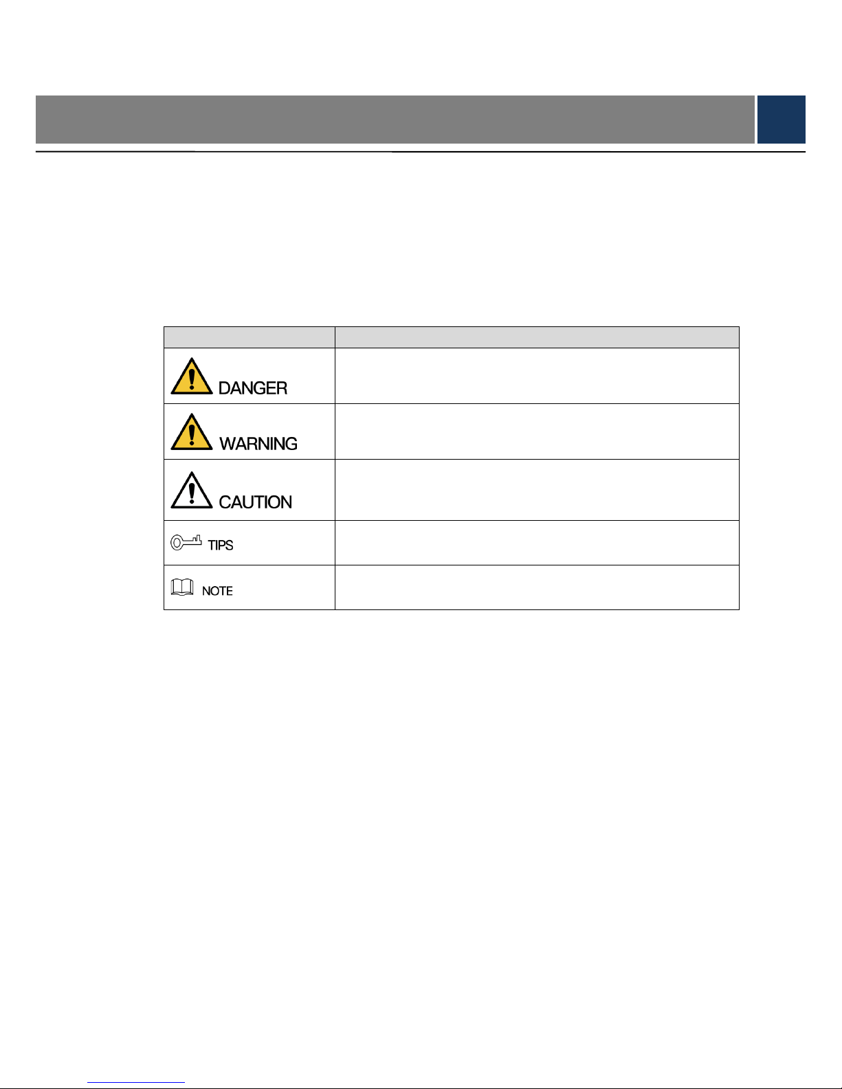
The following categorized signal words with defined meaning might appear in the Manual.
Signal Words
Meaning
Indicates a high p otential hazard which, if not avoided, will res ult in
death or serious injury.
Indicates a medium or low potential hazard which, if not avoided,
could result in slight or moderate injury.
Indicates a potential risk which, if not avoided, could result in
property damage, data loss, lower performance, or unpredictable
result.
Provides methods to help you solve a problem or save you time.
Provides additiona l information as the em phasis and s upplement to
the text.
Privacy Protection Notice
As the device user or data controller, you might collect personal data of others, such as face,
fingerprints, car plate number, Email address, phone number, GPS and so on. You need to be
in compliance with the local privacy protection laws and regulations to protect the legitimate
rights and interests of other people by implementing measures, including but not limited to:
providing clear and visible identification to inform data subject the existence of surveillance
area and providing related contact.
About the Manual
The Manual is for reference only. If there is inconsistency between the Manual and the
actual product, the actual pr oduct s hall prevail.
We are not liable for any loss ca used by the operat ions that d o not com ply wit h the Manua l.
The Manual would be updated according to the latest laws and regulations of related
regions. For detailed information, see the paper User's Manual, CD-ROM, QR code or our
official website. If there is inconsistency between paper User's Manual and the electronic
version, the electronic ver sion shall prevail.

Foreword VI
All the designs and sof tw ar e are su bject to ch ang e w ithout pr ior w ritt en not ice. The produ ct
updates might cause som e differe nces betw een the act ual produ ct and the Ma nual. Pleas e
contact the customer service for the latest program and supplementary documentation.
There still might be deviation in technical data, functions and operations description, or
errors in print. If there is any doubt or dispute, please refer to our final explanation.
Upgrade the reader software or try other mainstream reader software if the Guide (in PDF
format) cannot be opened .
All trademarks, registered trademarks and the company names in the Manual are the
properties of their respecti ve owners.
Please visit our website, contact the supplier or customer service if there is any problem
occurred when using the dev ice.
If there is any uncertaint y or controversy, please refer t o our final explanation.

Important Safeguards and Warnings VII
Important Safeguards and Warnings
The following description is the correct application method of the device. Please read the
manual carefully before use, in order to prevent danger and property loss. Strictly conform to
the manual during applica t ion an d keep it properly after read ing.
Operating Requirement
Please don’t place and install the device in an area exposed to direct sunlight or near heat
generating device.
Please don’t install the device in a humid, dusty or fuliginous area.
Please keep its horizontal installation, or install it at stable places, and prevent it from
falling.
Please don’t drip or splash liquids onto the device; don’t put on the device anything filled
with liquids, in order to prevent liquids from flowing into the device.
Please install the device at well-ventilated places; don’t block its ventilation opening.
Use the device only within rat ed input and output range.
Please don’t dismantle the device arbitrarily.
Please transport, use and store t he device w ithin allowed hu midity and tempe ratur e range.
Power Requirement
Please make sure to use batteries according to requirements; otherwise, it may result in
fire, explosion or burning ris ks of batteries!
To replace bat t er ies, only the same type of batteries can be used!
The product shall use electric cables (power cables) recommended by this area, which
shall be used within its rat ed specification!
Please use standard power adapter matched with the device. Otherwise, the user shall
undertake resulting personnel injury or device da m age.
Please use power supply that meets SELV (safety extra low voltage) requirements, and
supply power with rated v oltag e that co nforms to L imited Power Sourc e in IE C60950-1. For
specific power supply req uir ements, please refer to device labels.
Products with category I structure shall be connected to grid power out put s ocket , which is
equipped with protective gr ounding.
Appliance coupler is a di sconn ect ing dev ice. Durin g nor mal use, p lease keep an an gle th at
facilitates operation.

Table of Contents VIII
Table of Contents
Cybersecurity Recommendations ......................................................................................................... I
Regulatory Information ........................................................................................................................ IV
Foreword ................................................................................................................................................. V
Important Safeguards and Warnings ................................................................................................. VII
1 Overview .............................................................................................................................................. 1
1.1 Functional Feature ........................................................................................................................ 1
1.2 External Dimension ....................................................................................................................... 1
2 Installation Guide ................................................................................................................................ 3
2.1 System Struct ure ........................................................................................................................... 3
2.2 Device Installation ......................................................................................................................... 3
2.3 Disassembly .................................................................................................................................. 4
2.4 Wiring Diagram ............................................................................................................................. 5
2.4.1 Wiring Description o f Ex it But t on/Door Contact ..................................... 错误!
未定义书签。
2.4.2 Wiring Description o f External Alarm Input ............................................. 错误!
未定义书签。
2.4.3 Wiring Description of Alarm Output ........................................................ 错误!
未定义书签。
2.4.4 Wiring Description o f Loc k ...................................................................... 错误!
未定义书签。
2.4.5 Wiring Description o f Reader.................................................................. 错误!
未定义书签。
2.5 DIP Switch ..................................................................................................................................... 6
2.6 Reboot .......................................................................................................................................... 11
3 Smart PSS Config ................................................................................................................................ 12
3.1 Login Client ................................................................................................................................. 12
3.2 Add Access Controller ................................................................................................................. 12
3.2.1 Auto Search ...................................................................................................................... 12
3.2.2 Manual Add ....................................................................................................................... 14
3.3 Add User ..................................................................................................................................... 16
3.3.1 Card Type ......................................................................................................................... 17
3.3.2 Single Add ......................................................................................................................... 18
3.4 Add Door Group .......................................................................................................................... 20
3.5 Authorize ..................................................................................................................................... 22
3.5.1 Aut horize Accor ding to Door Group .................................................................................. 22
3.5.2 Authorize According to User ............................................................................................. 23
4 FAQ ....................................................................................................................................................... 25
1. Question: After pow er on, power indicator doesn’t tur n on or the buzzer doesn’t respond. ..... 25
2. Question: After the reader is connected with the device, card swiping light doesn’t turn on, and
it doesn’t respond after swiping a card. ............................................................................................ 25
3. Question: Client soft w ar e fa ils to det ect the device. ................................................................. 25
4. Question: After swiping ca r d, it prompts that card is invalid. ..................................................... 25
5. Question: Default IP of access controller. ................................................................................. 25
6. Question: Defau lt port, initial user name and p assword of access control ler. .......................... 25
7. Question: Online upgrad e of the device. ................................................................................... 25
8. Question: Max. wiring distance and transmission d istance of card reader and controller. ....... 25

Table of Contents IX
5 Technical Parameters ....................................................................................................................... 26
Overview 1
1 Overview
Four-door one-way access controller is a controlling device which compensates video
surveillance and visual intercom. It has neat and modern design with strong functionality,
suitable for commerc ial building, corporation property and intelligent community.
1.1 Functional Feature
Its rich functions are as fo llows:
Adopt slide rail and lock-controlled design, convenient installation a nd maintenance.
Integrate alarm, access cont r ol, video surveillance and fire alarm.
Support 4 sets of card rea ders .
Support 9 groups o f sig nal input (exit button*4, door contact*4 and intrusion alarm*1).
Support 5 groups of control output (electric lock *4 and a larm output *1).
With RS485 port, it may extend t o connect control module.
FLASH sto rage capaci ty is 16M (which may extend to 32M). Support max. 100,000 card
holders and 150,000 card readi ng records.
Support illegal intrusion alarm, unlock timeout alarm, duress card and duress code setup.
Also support black-white lis t and patrol card setup.
Support valid time period setting, password setting and expiration date setting of cards.
Regarding guest card, its time of use can be set.
Support 128 groups of sc hedules and 128 groups o f ho lid ay schedules.
Permanent data storage during outage, built-in RTC (support DST), online upgrade.
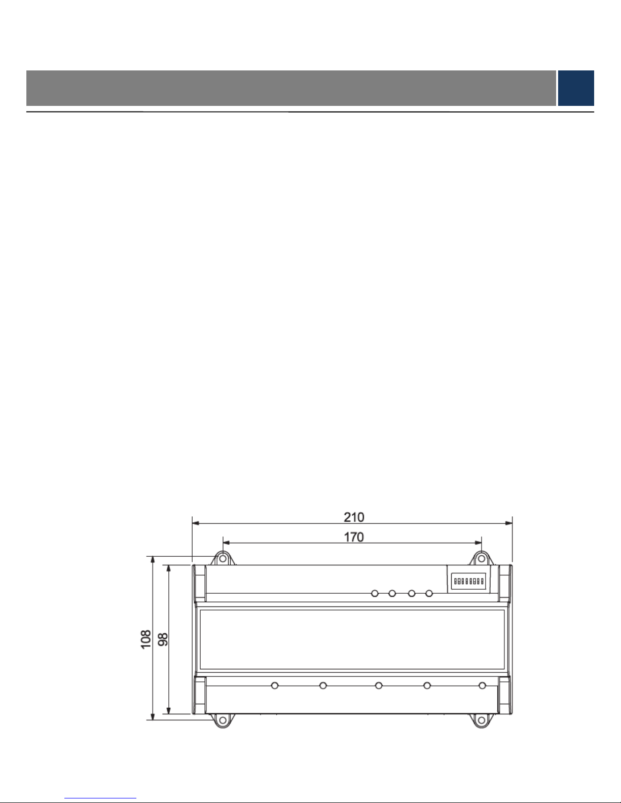
1.2 External Dimension
Its appearance and dimension is shown in Figure 1-1 and Figure 1-2. The un it is mm.
Figure 1-1

Overview 2
Figure 1-2

Installation Guide 3
2 Installation Guide
2.1 System Structure
System structure of four-d oor one-way access controller, door lock and reader is show n in
Figure 2-1.
Figure 2-1
2.2 Device Installation
There are two installation modes.
Mode 1: fix the whole device onto t he w al l w ith s cr ews.
Mode 2: with U-shaped guide rail, hang the whole device onto the wall (the U-shaped
guide rail is an optional fitting).
Mode 1
Installation diagram is sh own in Figure 2-2.

Installation Guide 4
Figure 2-2
Mode 2
Installation diagram is shown in Figure 2-3.
Figure 2-3
Step 1 Fix the U-shaped guide rail onto the wall with screws.
Step 2 Buckle the upper rear part of the device into upper groove of the U-shaped gui de r ai l.
Step 3 Push the snap joint at the bottom of the device upwards . The installation is completed
when you hear the fitting sound.
2.3 Disassembly
If the device is installed w ith mode 2, please disassemble it accor ding to Figure 2-4.
Align a screwdriver with th e snap joint, press it down and the snap jo int w il l po p up, so the
whole device can be disasse mb led smoothly.

Installation Guide 5
Figure 2-4
2.4 Wiring Diagram
2.4.1 Wiring Description of Access Controller
This device supports four-door in or out. In case of alarm input, trigger external alarm output
device to give an alarm. Device w iri ng diagram is shown in Figure 2-5.
Figure 2-5
Interfaces are described in Table 2-1.
Table 2-1
No.
Port Description
No.
Port Description
1 RS485 communication 7 Reader of door 1
2 Exit button and door contact 8 Reader of door 2
3 Alarm input/output 9 Reader of door 3
4 Lock control output 10 Reader of door 4
5 DIP switch 11 Reboot
6 TCP/IP, software platform port 12 DC 12V power port

Installation Guide 6
Indicator lights are descr i bed in Table 2-2.
Table 2-2
No. Description
13
Lock status indicator
14
15
16
17 Power indicator
2.4.2 Wiring Description of Exit Button/Door Contact
Corresponding wiring terminals of exit button and door contact are shown in Figure 2-6. Please
refer to Table 2-3 for descriptions of wiring terminals.
Figure 2-6
Table 2-3
Port
Wiring Terminal
Description
Exit button+ door
contact
PUSH1 Exit button of door 1
GND
Shared by exit button of door 1 and door contact
input of door 1
SR1
Door contact input of door 1
PUSH2 Exit button of door 2
GND
Shared by exit button of door 2 and door contact
input of door 2
SR2
Door contact input of door 2

Installation Guide 7
Port
Wiring Terminal
Description
PUSH3
Exit button of door 3
GND
Shared by exit button of door 3 and door contact
input of door 3
SR3 Door contact input of door 3
PUSH4
Exit button of door 4
GND
Shared by exit button of door 4 and door contact
input of door 4
SR4 Door contact input of door 4
2.4.3 Wiring Description of Lock
Support 4 groups of lock control outputs; serial numbers after the terminals represent
corresponding doors. Please choose a proper connection mode according to lock type, as
shown in Figure 2-7, Figure 2-8 and Figure 2-9. Please refer to Table 2-4 for descriptions of
wiring terminals.
Figure 2-7
Figure 2-8

Installation Guide 8
Figure 2-9
Table 2-4
Port
Wiring Terminal
Description
Lock control output
port
NC1
Lock control of door 1
COM1
NO1
NC2
Lock control of door 2
COM2
NO2
NC3
Lock control of door 3
COM3
NO3
NC4
Lock control of door 4
COM4
NO4
2.4.4 Wiring Description of Reader
1 door only supports to connec t one type of reader—485 or Wiegand.
Please refer to Table 2-5 for descriptions of wiring terminals corresponding to readers. Take
door 1 for example; other readers are the same. Please refer to Table 2-6 for descriptions of
reader cable specificatio n and length.
Table 2-5
Port
Wiring Terminal
Cable Color
Description
Entry Reader of
Door 1
485+
Purple
485 reader
485-
Yellow
LED Brown
Wiegand reader
D0 Green
D1 White
CASE Blue
GND Black
Reader power supply
12V Red

Installation Guide 9
Table 2-6
Reader T ype
Connection Mode
Length
485 Reader CAT5e network cable, 485 connection 100m
Wiegand Reader CAT 5e network cable, Wiegand con nec t i on 100m
2.4.5 Wiring Description of External Alarm Input
External alarm input connection is shown in Figure 2-10. Please refer to Table 2-7 for
descriptions of wiring ter m inals.
Figure 2-10
Table 2-7
Port
Wiring Terminal
Description
External alarm
input
ALM-IN External alarm input ports
are able to connect
smoke detector and IR det ect or et c..
When external alarm is trigger ed, all doors are
linked to be normally open.
GND
2.4.6 Wiring Description of Alarm Output
With 1-ch alarm output, after internal alarm input (such as door timeout) or ext er nal a larm input
triggers an alarm, the alarm output device gives an alarm for 15s .
There are two connection modes of alarm output, depending on alarm device. For example,
IPC can use Mode 1, whereas audible and visual siren can use Mode 2, as shown in Figure
2-11 and Figure 2-12. Please refer to Table 2-8 for descriptions about wiring terminals.
Figure 2-11

Installation Guide 10
Figure 2-12
Table 2-8
Port
Wiring Terminal
Description
Alarm output
OUT1+
ALM-IN
triggers alarm
output.
Door timeout and
intrusion alarm output.
Tamper alarm output of
reader
Internal and external
alarm output ports are
able to connect audible
and visual sirens.
OUT1-
2.4.7 Description of Alarm Input and Output Rule
In case of alarm event, access controller can control the acc ess and external alarm status.
Please refer to Table 2-9 for detailed alarm input and output rule s.
Table 2-9
Alarm
Type
Alarm Event Alarm Signal
Input Port
Alarm Signal
Output Port
Alarm Status
External
alarm
input
Trigger no. 1 alarm
detector
ALM1 OUT1
No. 1 alarm
gives an alarm,
and links all
doors to be
normally open.
Internal
alarm
input
Intrusion alarm or
unlock timeout alarm
of no. 1 door
SR1
OUT1
No. 1 alarm
gives an alarm.
Intrusion alarm or
unlock timeout alarm
of no. 2 door
SR2
Intrusion alarm or
unlock timeout alarm
of no. 3 door
SR3
Intrusion alarm or
unlock timeout alarm
of no. 4 door
SR4
Tamper alarm of no. 1
door reader
RS-485/CASE
Tamper alarm of no. 2 RS-485/CASE

Installation Guide 11
Alarm
Type
Alarm Event Alarm Signal
Input Port
Alarm Signal
Output Port
Alarm Status
door reader
Tamper alarm of no. 3
door reader
RS-485/CASE
Tamper alarm of no. 4
door reader
RS-485/CASE
2.5 DIP Switch
Operate with DIP sw itch.
Figure 2-13
the switch is at ON position, meaning 1.
the switch is at the bottom, meaning 0.
1~8 are all 0; the system is started normally.
1~8 are all 1; the system enter s BOOT mode after start.
1, 3, 5 and 7 are 1, while others are 0. After reboot, the system restores factory defaults.
2, 4, 6 and 8 are 1, while others are 0. After reboot, the system restores factory defaults,
but user info is retained.
2.6 Reboot
Insert a needle into reboot hole, press it once to reboot the device.
Reboot button is to reboot t he device, rather than modifying configuration.

Smart PSS Config 12
3 Smart PSS Config
Access controller is managed with Smart PSS client, so as to realize control and right
configuration of one door and door groups.
This chapter mainly introduces quick configuration. For specific operations, please refer to
User’s Manual of Smart PSS Client.
Smart PSS client of fers different ports for different versions. Please refer to actual port.
3.1 Login Client
Install the matching Smart PSS client, and double click to run. Carry out initialization
configuration according to interface prompts and c omplete login.
3.2 Add Acces s Controller
Add access controller in Smart PSS; select “Auto Search” and “ Add”.
3.2.1 Auto Search
Devices are required to be in the sa m e net work segment.
Step 1 In “Devices” interface, click “Auto Search”, as shown in Figure 3-1
.
The system displays “Aut o Sear ch” interface, as shown in Figure 3-2.
Figure 3-1

Smart PSS Config 13
Figure 3-2
Step 2 Input device segment and click “Search”.
The system displays sear ch r esults.
Click “Refresh” to update device information.
Select a device, click “Modify IP” to modify IP address of the device. For speci fic
operations, please refer to User’s Ma nual of Smart PSS Client.
Step 3 Select the device that needs to be added, and clic k “Add”.
The system pops up “Prompt”.
Step 4 Click “OK”.
The system displays “Login Infor mation” dialogue box, as shown in Figure 3-3.
Figure 3-3
Step 5 Input “User Name” and “Password” to log in the dev ice, and cl ick “OK”.
The system displays the added device list, as shown in Figure 3-4. Please refer to
Table 3-1 for details.

Smart PSS Config 14
After completing adding, the system continues to stay at “Auto Search” interface.
You can continue to add more devices, or click “Cancel” to exit “Auto Search”
interface.
After completing adding, Smart PSS logs in the device automatically. In case of
successful login, online status displays “Online”. Otherwise, it displays “Offline”.
Figure 3-4
Table 3-1
Icon
Description
Click this icon to enter “Modify Device” interface and mo di fy device
info, including device nam e, I P/ dom ai n name, port, user name and
password.
Alternatively, double click the device to enter “Modify Device”
interface.
Click this icon to enter “Device Config” interface and configure device
camera, network, event, s t or age and system info.
and
When the device is online, the icon is . Click this icon to exit
login, and this icon turns to
.
When the device is offline, the icon is . Click this icon to login
(with correct device info), and this icon turns to
.
Click this icon to delete the device.
3.2.2 Manual Add
To add devices, device IP address or domain name shall be known first.
Step 1 In “Devices” interface, click “Add”, as shown in Figure 3-5
.
The system pops up “Ma nual Add” interface, as shown in F igure 3-6.
Figure 3-5

Smart PSS Config 15
Figure 3-6
Step 2 Set device parameters. For specific par ameter descriptions, pleas e r efer to Table 3-2
.
Table 3-2
Parameter
Description
Device Name
It is suggested that device should be named by the
monitoring zone, so as to facilitate maintenance.
Method to add
Select “IP/Domain Name”. Add devices according to
device IP address or do m ain n ame.
IP/Domain Na me IP address or domain name o f the device.
Port
Port number of the device. Default port number is
37777. Please fill in accordin g to actual conditions.
Group Name Select the group of the dev ice.
User Name and Password User name and password of the device.
Step 3 Click “Add” to add a device.
The system displays the added device list, as shown in Figure 3-4. Please refer to
Table 3-1 for operation interface. Doors of the added controller are displayed under
“Access” tab, as shown in Figur e 3-7.
To add more devices, click “Save and Continue”, add devices and stay at “Manual
Add” interface.
To cancel the adding, click “Cancel” and exit “ M anual Add” int er f ace.
After completing adding, Smart PSS logs in the device automatically. In case of
successful login, online status displays “Online”. Otherwise, it displays “Offline”.

Smart PSS Config 16
Figure 3-7
3.3 Add User
Add users and bind with cards, s o as t o distribute authority.
In “New” interface, c l ick “Access” to enter “Access” i nt er fac e, and complete access config here.

Smart PSS Config 17
Figure 3-8
3.3.1 Card Type
Card type shall be the same with c ard issuer; otherwise, it fails to r ead car d number .
In “Access” interface, click and then click to set the card type, as shown in Figure
3-9 and Figure 3-10.

Smart PSS Config 18
Figure 3-9
Figure 3-10
3.3.2 Single Add
Add a single user, send a card and input user in fo.
Step 1 In “Access” interface, click
, and then click , as shown in Figure 3-11.
The system pops up “Add User” dialog box, as shown in Figure 3-12.

Smart PSS Config 19
Figure 3-11
Figure 3-12
Step 2 Add user info manually, including basic info, fi ngerprint info and details. Pl ease refer to
Table 3-3 for details.

Smart PSS Config 20
Table 3-3
Parameter
Description
Basic Info
User ID (mandatory).
Name (mandatory).
Department (auto association).
Card No.: input by card reader or in put manually.
Card type: general card, VIP card, guest card, patrol card,
blacklist card and duress car d.
Card Password: it is used to open the door with
card +
password.
Unlock Password: it is use d t o open t he door with password.
Number of Use: it only applies t o guest card.
Valid Time: set the valid time of card, which is 10 years by
default.
Picture: user picture, max. 120K.
Card no. and user ID cannot be repe at ed.
Fingerprint Info
Collect fingerprints w it h f ingerprint reader and acces s r eader.
Max. 2 fingerprints for every person.
Support to enter fingerprint name.
Details Fill in detailed user in fo according to interface parameters.
Step 3 Click “Finish” to finish adding the users.
3.4 Add Door Group
Divide doors into group s and manage them together.
Step 1 In “Access” interface, click
, and then click “Access Level”, as shown in Figure
3-13.

Smart PSS Config 21
Figure 3-13
Step 2 Click “Add”.
The system pops up “Add Door Grou p” dialog box, as shown in Figure 3-14.
Figure 3-14

Smart PSS Config 22
Step 3 Enter “Name”; select “Tim e Zone” and doors to be managed.
Step 4 Click “OK” to complete adding.
3.5 Authorize
Grant users authorities ac cor di ng t o door gr oup and user.
3.5.1 Authorize According to Door Group
Select a door group, add corresponding users to the group, so all users in the group obtain
authority of all doors in the group.
Step 1 In “Access” interface, click
, and then click “Access Level”, as shown in Figure
3-15.
Figure 3-15
Step 2 Click .
The system pops up “User Select” dialog box.
Step 3 Select the user’s department from dropdown list, or enter the us er’s ID or name directly,
as shown in Figure 3-16.

Smart PSS Config 23
Figure 3-16
Step 4 In the search list, select the user and add to user list.
Step 5 Click “OK” to finish authorization.
The search list filters user in fo w ithout card number.
In the user list, cancel the added user and delete the user’s authority.
3.5.2 Authorize According to User
Select a user, distribute door group and grant door group authority t o the user.
Step 1 In “Access” interface, click
, and then click “User Right”, as shown in Figure 3-17.

Smart PSS Config 24
Figure 3-17
Step 2 Click
.
The system pops up “Sel ect Door Group” dialog box , as shown in Figure 3-18.
Figure 3-18
Step 3 Select the door group and click “OK” to finish authorization.

FAQ 25
4 FAQ
For problems not included hereinafter, please contact local customer service personnel or
consult headquarter customer service personnel. We will be always at y our ser vice.
1. Question: After power on, power indicator doesn’t turn on or the buzzer doesn’t
respond.
Answer: Please check whether power plug is inserted in place. Please pull it out and insert it
again.
2. Question: After the reader is connected with the device, card swiping light doesn’t
turn on, and it doesn’t respond after swiping a card.
Answer: Please check whether reader connector is inserted in place. Please pull it out and
insert it again; check whether r eader contact light turns on.
3. Question: Client software fai l s t o detect t he device.
Answer: Please check whether TC P/IP connector is connected prop erly, and whether device IP
is in the same network segment .
4. Question: Aft er swiping card, it prompts t hat card is invalid.
Answer: Please check whether this card number has been a dded in the controller.
5. Question: Default IP of access contr ol l er.
Answer: Default IP address is 192.168.0.2.
6. Question: Default port, initial user nam e and password of access controller.
Answer: Default port is 37777, initial user name is admin and password is 123456.
7. Question: Online upgrade of the device.
Answer: Connect the device and platform throu gh network, and upgrade it at the pl atform.
8. Question: Max. wiring distance and transmission distance of card reader and
controller.
Answer: It depends on netw or k c abl e type and whether it needs pow er supply of control relay.
Connected with CAT5E network cable, typical value is:
RS485, 100m.
Wiegand, 100m.

Technical Parameters 26
5 Technical Parameters
Parameter
Specification
Processor 32-bit ARM processor
External power supply
12V 0.5A
, and working temperature shall be
5℃~55℃.
Memory capacity 16M
Max. number of user 100,000
Max. storage record 150,000
Communication port of reader Wiegand, RS485
Communication port of platform TCP/IP
Number of connected reader 4 groups
Working power supply Rated voltage 10V-15V DC, rated current 0.75A
Period 128
Holiday 128
Unlocking mode
C
ard, card + password, password, card or
password, card + fingerprint, fingerprint +
password, fingerprint or card or password, by
period
Cross-segment networking Support
Two-door interlocking Support
Real-time surveillance Support
Fire alarm linkage Support
Tamper alarm Support
Intrusion alarm Support
Unlock timeout alarm Support
Duress card and code setting Support
DST and RTC Support
Online upgrade Support
 Loading...