

Page 1

DH-HWS200+ Radar Speed Measuring System
User’s Manual
Page 2

Welcome
Thank you for purchasing our product!
This user’s manual is designed to be a reference tool for your system.
Please read the following safeguard and warnings carefully before you use this series product!
Please keep this user’s manual well for future reference!
Note:
This equipment has been tested and found to comply with the limits for a Class A digital device,
pursuant to part 15 of the FCC Rules. These limits are designed to provide reasonable
protection against harmful interference when the equipment is operated in a commercial
environment. This equipment generates, uses, and can radiate radio frequency energy and, if
not installed and used in accordance with the instruction manual, may cause harmful
interference to radio communications. Operation of this equipment in a residential area is likely
to cause harmful interference in which case the user will be required to correct the interference
at his own expense.
Changes or modifications not expressly approved by the manufacturer could void the user’s
authority to operate the equipment.
Page 3

Important Safeguards and Warnings
1.Electrical safety
All installation and operation here should conform to your local electrical safety codes.
We assume no liability or responsibility for all the fires or electrical shock caused by improper handling
or installation.
We are not liable for any problems caused by unauthorized modification or attempted repair.
2.Installation
This series product shall be installed one or three meters away from the lane. The default angle
between the radar and the road is 22°(The error value shall be less than or equal to ±1° ). The
product shall face the road .The road shall be plain and no turning point.
3.Environment
It shall be installed away from the large-size metal object or strong magnetic area.
4. Lithium battery
Improper battery use may result in fire, explosion, or personal injury!
When replace the battery, please make sure you are using the same model!
5. Accessories
Please open the accessory bag to check the items one by one in accordance with the list below.
Contact your local retailer ASAP if something is missing or damaged in the bag.
Content
Quality
Remote control (Optional)
1
Power adapter
1
Charger
1
User’s manual
1
Certificate Card
1
Flash disk
1
Warning!
Please make sure you have removed the USB device before you boot up the system!
Page 4

Table of Contents
1 General Introduction ....................................................................................................................... 6
1.1 Overview ............................................................................................................................. 6
1.2 Functions ............................................................................................................................ 6
1.3 Features.............................................................................................................................. 7
1.4 Specifications .................................................................................................................... 8
1.5 Chinese National and Industry Criteria ........................................................................ 9
2 Structure .......................................................................................................................................... 10
2.1 Appearance...................................................................................................................... 10
2.2 Panel and Ports .............................................................................................................. 11
2.2.1 Right Panel ............................................................................................................... 11
2.2.2 Front Panel ............................................................................................................... 12
2.2.3 Left Panel .................................................................................................................. 13
2.3 Remote Control ............................................................................................................... 14
3 Installation ....................................................................................................................................... 16
3.1 Device Installation .......................................................................................................... 16
3.2 Camera Debug ................................................................................................................ 16
3.3 Radar Debug ................................................................................................................... 16
3.4 Mobile Flashlight Installation ........................................................................................ 16
4 Operation ........................................................................................................................................ 17
4.1 Boot up and Shut down ................................................................................................. 17
4.1.1 Boot up ...................................................................................................................... 17
4.1.2 Shut Down ................................................................................................................ 17
Page 5

4.1.3 Input Method ............................................................................................................ 17
4.2 Menu Operation .............................................................................................................. 17
4.2.1 Main Interface .......................................................................................................... 17
4.2.2 Snapshot ................................................................................................................... 18
4.2.3 Road Monitor ............................................................................................................ 19
4.2.4 System Setting ......................................................................................................... 20
4.2.5 Image Search ........................................................................................................... 27
4.2.6 Image Backup .......................................................................................................... 29
4.2.7 System Information ................................................................................................. 33
5 FAQ .................................................................................................................................................. 42
5.1 About the Touch Panel .................................................................................................. 42
5.2 About the Lithium Battery ............................................................................................. 42
5.3 About the Radar .............................................................................................................. 42
5.4 About the Camera .......................................................................................................... 42
6 Applications .................................................................................................................................... 44
6.1 Approaching Snapshot in the Daytime ...................................................................... 44
6.2 Departing Snapshot in the Daytime ........................................................................... 44
6.3 Approaching Snapshot at Night .................................................................................. 45
6.4 Departing Snapshot at Night ........................................................................................ 46
Page 6

6
1 General Introduction
1.1 Overview
The DH-HWS200+ mobile speed measuring system is a full embedded system featuring vehicle
speed measurement, image snapshot and etc.
This series product perfectly meets the requirement of the traffic business of the public security
and generally integrates the advantages of the domestic and overseas products.
The built-in design is stable and of strong function. It is easy to use and very convenient to install.
It can be widely used in many areas.
This series product also integrated the Dahua’s technical advantages in the security area. It is a
perfect product integrating the security area and the intelligent transportation system together.
1.2 Functions
Vehicle
image
snapshot
Accurately snapshot the
speeding vehicle image
according to the speed limit
you set. At the same time, it
can overlay the vehicle
information such as the
snapshot position, snapshot
time, vehicle real-time speed,
road speed limit, measure
direction, system serial
number.
Vehicle
speed
measurement
Radar speed measurement
can quickly and accurately test
the vehicle speed. Support
customized speed value (The
speed value ranges from
20km/h to 250km/h.).Support
the multiple-lane speed
measurement and extra low
vehicle speed measurement.
Dynamically
real-time
preview
function
Provide dynamically real-time
preview function. Support
display the lane real-time
monitor information via the
LCD.
Auto alarm
Customized speed limit. There
is an on-site alarm and remote
alarm when the vehicle speed
is too low or too high.
Data search
Application platform supports
the vehicle information
search. Various user right
levels supported. Fuzzy
search and data backup also
supported.
Data
transmission
and remote
maintenance
Data transmission, remote
access and remote system
maintenance are realized via
Ethernet.
USB backup
USB 2.0 port is available.
Support USB data backup and
USB hot swap function.
Support backup the images of
one or more days to the USB
device.
Software
upgrade
System supports the host
software remote upgrade and
local upgrade. System can
resume previous working
status after upgrade.
Multiple
human and
machine
alternating
ports
There are two alternating
ports between the human and
machine: remote control and
the touch panel. It is useful for
your operation.
Log search
System can record the device
key operations and support log
search function.
Auto
maintenance
function
Support auto maintenance
function and customized
maintenance period. System
can restore previous working
status after the reset
operation.
Page 7

7
1.3 Features
Fully embedded design without PHD, stable and reliable system
Comparing the speed measuring system consists of the PHD and digital camera, this series
product featuring the compact design, stable performance and is very convenient to use. It is free
of the PC virus and OS vulnerability.
The DH-HWS200+ series product adopts the Dahua’s technical advantages in the security area.
The host software circuit adopts the mature platform Dahua has already used in the security area.
The hardware circuit is also be optimized and perfected to use in the industry-level or military
level chips, which lowers the system power consumption and can guarantee the long time
running period in the harsh environments. The full real-time embedded operating system and
unique software specifications enhance the system working efficiency and stability. The dual
watch dogs (software and hardware) technology absolutely prevents the system from downing.
Integrated design, compact construction, easy to install, use and maintain
DH-HWS200+ series product integrates the high definition camera, host, LCD, power, speed
measurement radar, storage disk and etc together. The compact construction and integrated
design allows it to be used in either stationary or mobile environments.
Built-in special image storage device, support over 10, 000 offence images
The built-in special large capacity disk meets the requirement of data safety and mobile speed
measurement device. It supports the short-time local storage and data backup. At the same time,
the system can upload the image to the centre server simultaneously to storage, backup and
review, which realizes dual storage at the local-end and the centre.
Narrow pulse light technology
This series product integrates the Dahua self-developed adjustable narrow pulse light technology.
The vehicle driver even can not notice the short time pulse light, which can eliminate the strong
light effects to the driver’s eyes. It can not only clearly snapshot the plate, but distinguish the
vehicle type and the face feature of the driver and passengers, which can provide the irrefutable
offence evidence.
Narrow beam radar speed measurement to enhance the accuracy, effectively hide
from the electronic dog (anti-speed radar detector)
Dahua self-developed narrow wave radar can meet the international speed measurement
accuracy. The narrow beam radar is rarely detected by the electric dog. It can effectively monitor
the approaching and departing vehicles.
Industry-level component and high reliable socket connector
The hardware circuit design adopts the industry-level components. The system is of low power
consumption, high reliability. The built-in Lithium battery can averagely work as long as 8 hours.
The imported reliable socket connector such as Lemo connector and air-level connector further
guarantees the system reliability.
High definition image snapshot
Page 8

8
There is a 2 mega high definition CCD camera to snapshoot the offence vehicle. System can
overlay information such as the vehicle speed, snapshot time, snapshot position. The built-in
watermark function prevents the vicious image modification, which maximally guarantees the
authentic image.
General management and remote maintenance function
System supports remote maintenance function. Supports the remote malfunction diagnosis,
malfunction alarm and fix remotely, which greatly reduce the maintenance work load.
Extra low power consumption, support solar power
The whole system average power consumption is below 20w, completely support the solar power.
1.4 Specifications
Host
Spec
Vehicle capture rate:≥99%
Measure range:(20~250)km/h
Special camera exposure time:7-level (Selectable)
Storage capacity:8 G
Snapshot resolution:1600*1200
Video resolution:VGA(640*480)
Transmission mode:TCP/IP, FTP (Selectable)
Image format:JPEG
Image amount:2
Record mode:Image
Video input:1 channel
Video output :1 channel
Alarm input:2 channels
Alarm output:1 channel
Data interface:One RS232 COM, one USB2.0 port,10/100M Ethernet
port.
Mean time between failures (MTBF): ≥30000h
Mean time to repair (MTTR): ≤30min
Lithium battery average working time:8h
Working voltage:DC19V±10%
GND resistance:≤4Ω
Average power consumption:<15W
Working temperature:-30~+70℃
Relative humidity:<95%,(no condensation)
Waterproof level:IP65
High definition lens port type :C type
Dimensions:237mm ×198mm ×264mm(W ×D×H)
Weight:9kg
Color:Silver grey and Iron grey
Meet 7×24h industrial environment continuous working requirement
Conform to the JJG527-2007 Automatic Monitor System for Vehicle Speeding
Conform to JJG528-2004 Vehicles Radar Measuring Speedometers
Conform to GA/T832-2009 Technology Specifications of Image Forensics for
Road Traffic Offences
Radar
Measure accuracy:±1km/h
Page 9

9
Spec
Working distance:>60m
Oscillation frequency:34.7GHz
Transmission power:≤10mW
Antenna beam width:horizontal 5 degrees (-3dB), vertical
15degrees (-3dB)
Reactive time:≤0.1s
Power voltage:DC 10.5~14.5V
Power consumption:The current is lower than 700mA when it is
the 12V rated voltage.
Working temperature:(-30~70)℃
Enclosure:High density industrial plastic
1.5 Chinese National and Industry Criteria
Law of the people's republic of China on road traffic safety
Regulation on the implementation of the law of the People's Republic of China on road traffic
safety
Specification for design and construction of expressway safety (JTJ 074-2003)
General specifications of intelligent monitoring and record (GA/T497-2004)
General specifications of intelligent monitoring and record(GA/T 497-2009)
Specifications for the construction of public security traffic command system(GA/T651-
2006)
General demand for the groundwork of public security traffic management equipments
outside
(
GA/T652-2006)
Specification of the design drawing for the public security traffic command system
(
GA/T515-2004)
Specification of engineering of security and protection system(GB50348—2004)
Specification of lightning-surge protection for security and protection system(GA/T 670-
2006)
Rules of engineering acceptance of TV monitoring system for traffic(GA/T 514-2004)
Vehicle speeding auto-monitor system (JJG527-2007)
Vehicle radar measurement device (JJG528-2004)
Technology specifications of image forensics for road traffic offences
(
GA/T832-2009
)
Chinese national and corresponding local regulations.
Page 10
10
2 Structure
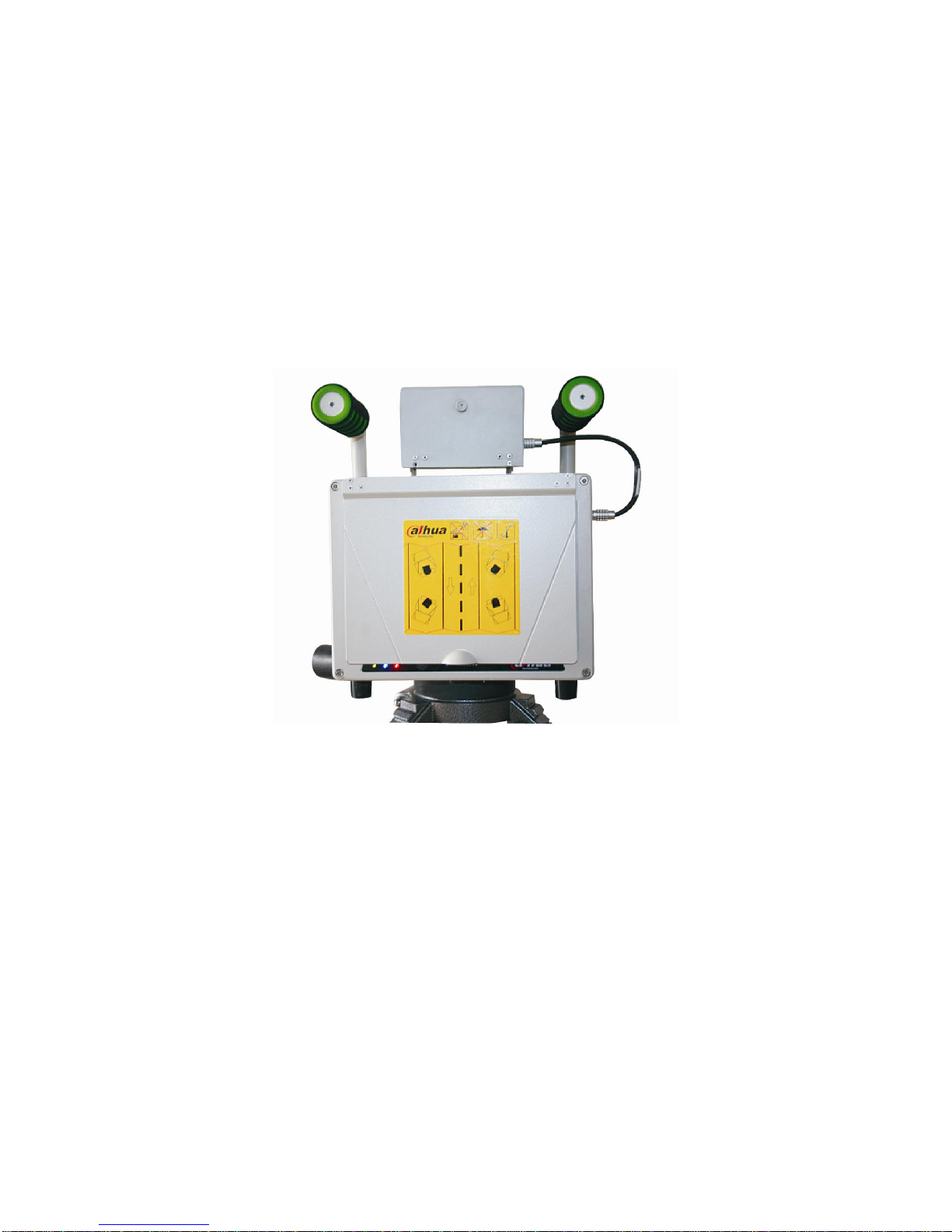
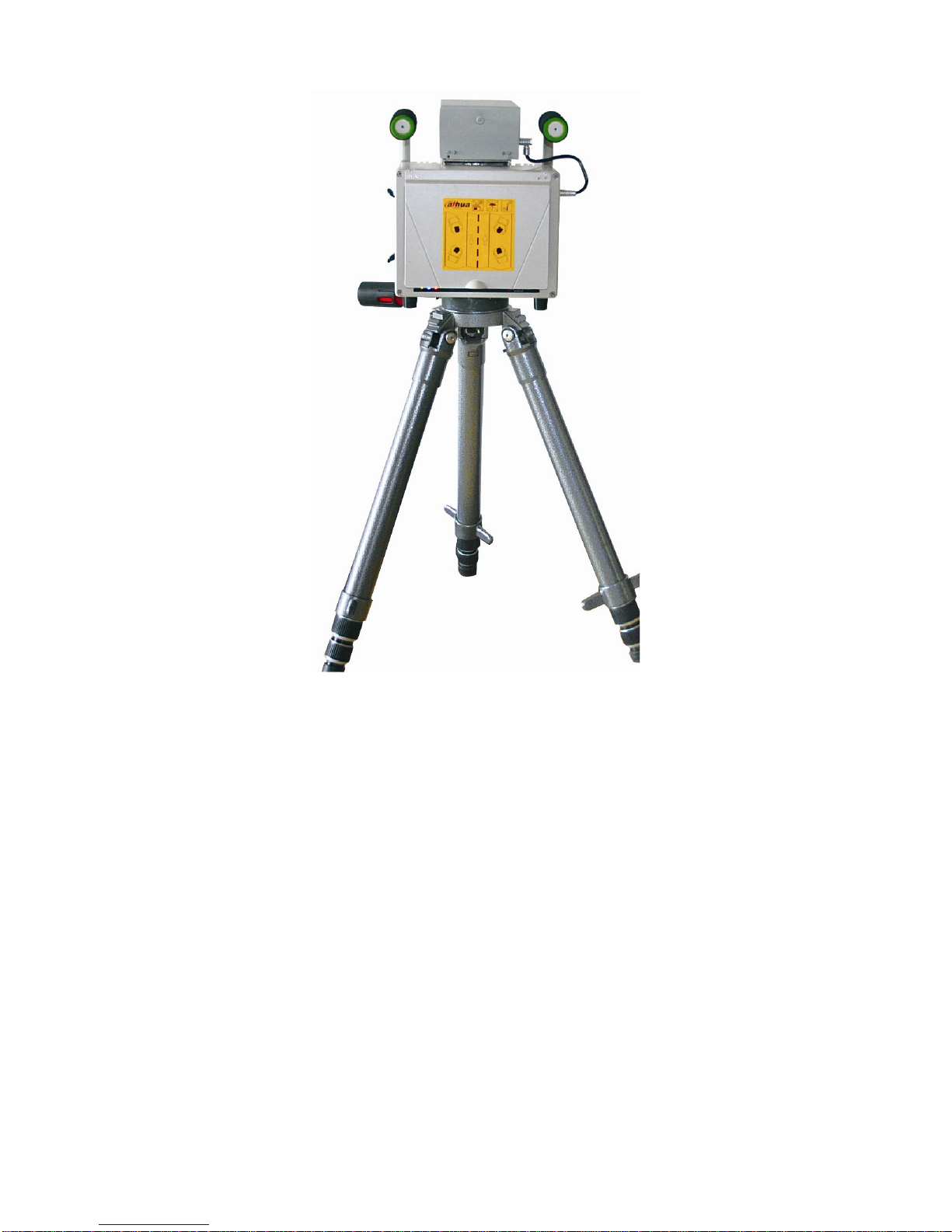
2.1 Appearance
This series product appearance is shown as below. See Figure 2-1 and Figure 2-2.
DH-HWS200+ Radar speed measuring system mainly consists of the power, embedded
snapshot module, flash light, radar and LCD. The embedded snapshot module is the key unit of
the whole system which is in charge of the image snapshot, flash light synchronization, camera
control, radar speed setup, getting the speed, disk storage, network transmission, USB download
and GUI display.
Figure 2-1
Page 11
11
Figure 2-2
2.2 Panel and Ports
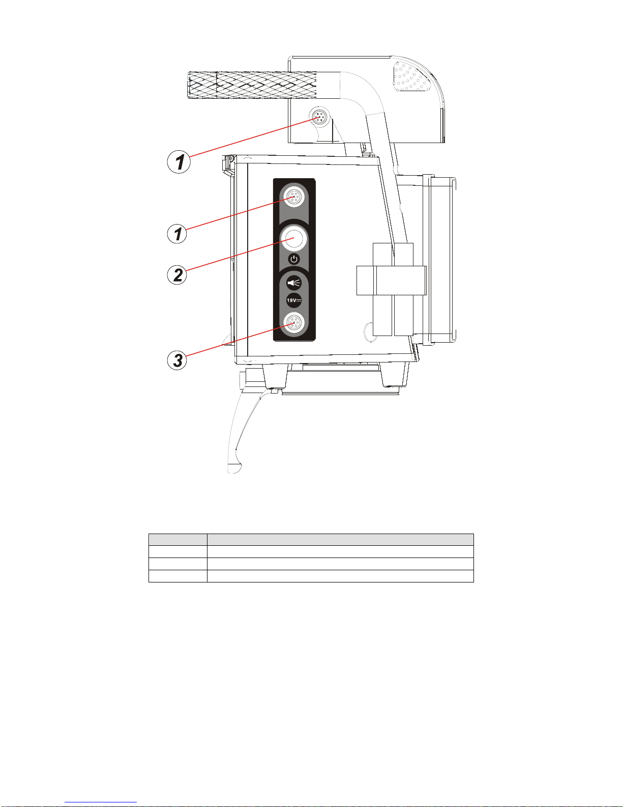
2.2.1 Right Panel
Please refer to the following figure for right panel information. See Figure 2-3.
Page 12
12
Figure 2-3
Please refer to the following sheet for detailed information.
SN
Port Name
1
Camera port
2
Power button
3
Flash light and DC19V power input port.
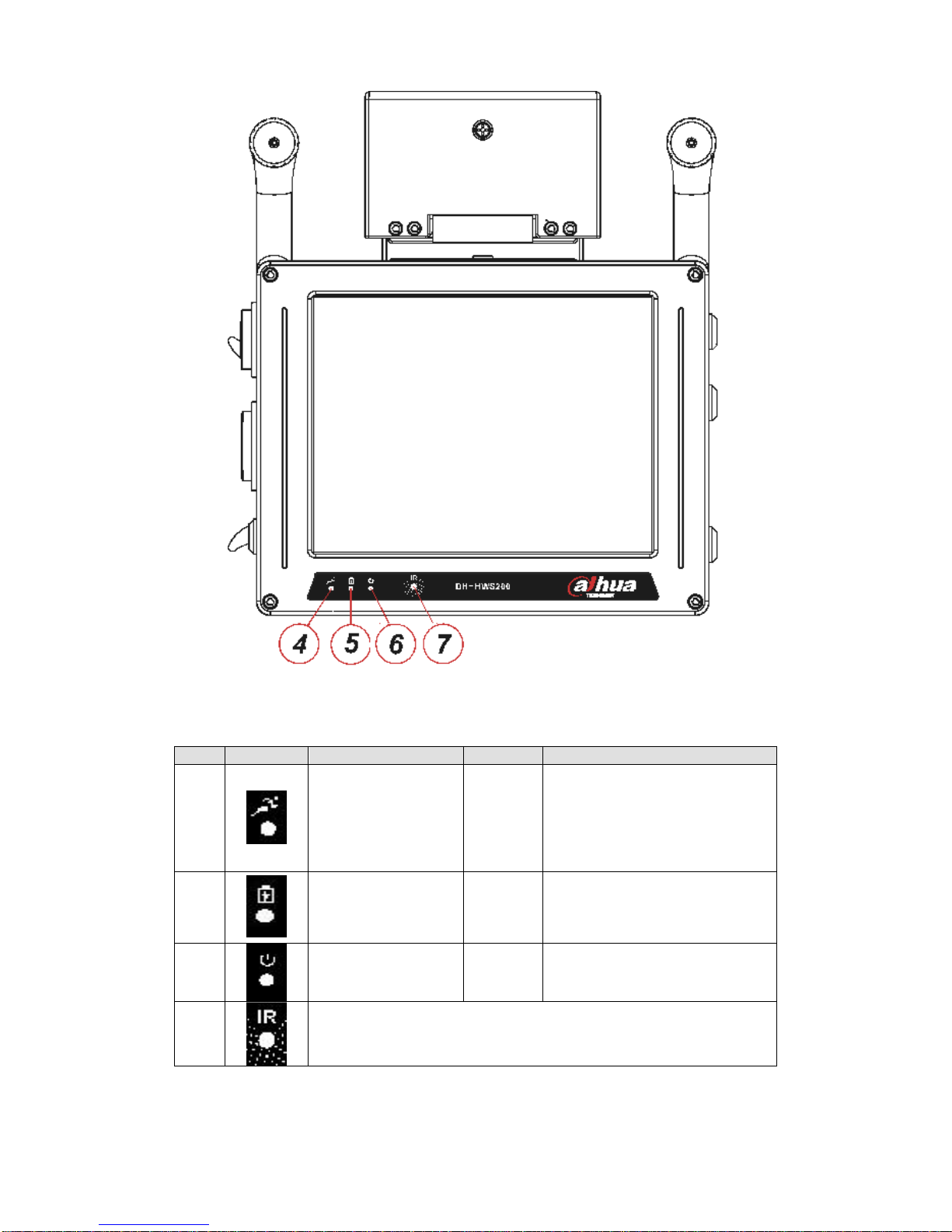
2.2.2 Front Panel
The front panel is shown as in Figure 2-4.
Page 13
13
Figure 2-4
Please refer to the following sheet for detailed information.
SN
Icon
Description
Color
Function
4
System running
indication light
Green
Flashing: System is working
properly.
On: System has stopped
working.
Off: system has stopped
working.
5
Lithium battery
recharge indication
light
Blue
Flashing: Lithium battery is
recharging now,.
On: The recharge is completed
or there is no battery available.
6 Power light
Red
On:System is on.
Off:System is off.
7 Receive the signal from the remote control.
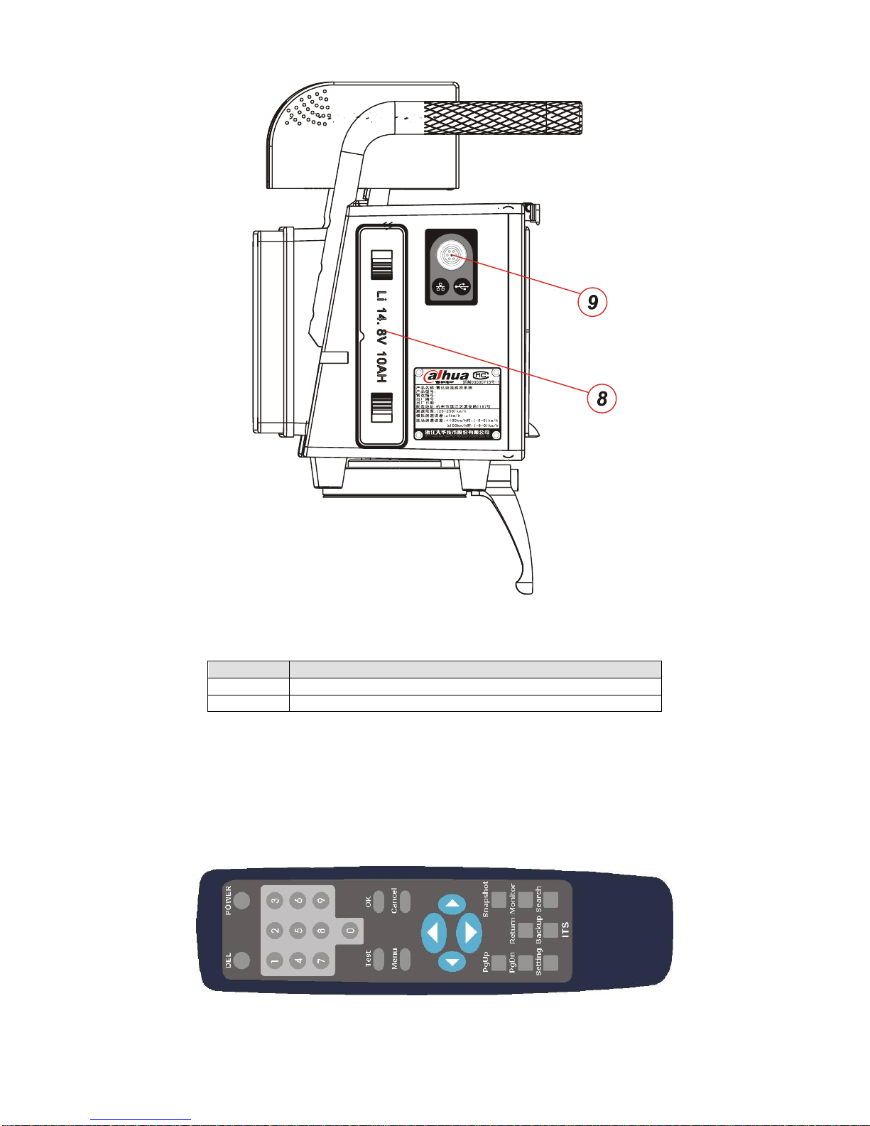
2.2.3 Left Panel
The system left panel is shown as below. See Figure 2-5
Page 14
14
Figure 2-5
Please refer to the following sheet for detailed information.
SN
Port Name
8
Lithium battery
9
Network, USB port, DC 12V power output and etc.
2.3 Remote Control
The remote control is shown as below. See Figure 2-6
Please note the remote control is an optional accessory and it is not included in the accessory
bag.
Figure 2-6
Page 15

15
Please refer to the following sheet for detailed information.
Name
Function
POWER
It is the on/off button to shut down/boot up the LCD
power or switch between the working/standby modes.
Press the POWER button once; you can close the LCD
power.
Press the POWER for a long time to go to the standby
mode.
DEL
It is to delete the selected record in the Search Results
interface (chapter 4.2.5 Image Search).
0-9
Input number 0-9
OK
Confirm current operation, save setting data.
Cancel
Cancel current operation; go back to the previous
menu.
Test
It is a short-cut menu to realize the snapshot
manually.
Menu
Go to the main interface.
Direction buttons
Move the cursor up/down/left/right.
PgUp
Go back to the previous page
PgDn
Go to the next page.
Return
Go back to the previous menu.
Snapshot
It is a short-cut menu to go to the Snapshot
interface.(Chapter 4.2.2 Snapshot)
Monitor
It is a short-cut menu to go to the Road Monitor
interface.(Chapter 4.2.3 Road Monitor)
Setting
It is a short-cut menu to go to the System Setting
interface.(Chapter 4.2.4 System Setting)
Backup
It is a short-cut menu to go to the Image Backup
interface.(Chapter 4.2.6 Image Backup)
Search
It is a short-cut menu to go to the Image Search
interface.(Chapter 4.2.5 Image Search).
Page 16

16
3 Installation
3.1 Device Installation
Take the device out of the box.
Insert the Lithium battery.
Put the device on the tripod and adjust to the proper height.
Push the power button to boot up the device.
3.2 Camera Debug
Go to the Road Monitor interface.
Adjust the lens iris according to the actual environment.
Adjust the lens focus distance and definition to the proper effect.
Important
Please adjust the lens focus distance to make the middle lane clear. For example, there are
three lanes, and then you can adjust the lens to clearly snapshoot the second lane.
3.3 Radar Debug
The device shall be installed from one to three meters away of the road.
The device and the road angle shall be 22°(≤±1°).
Important
The vehicle head and vehicle rear snapshot angle default value is 22°.
3.4 Mobile Flashlight Installation
Use the accumulator to provide power to the 12V DC flashlight
The device is 5 meters away from the flashlight. The flashlight bracket is 1.5 meters height.
Adjust the flashlight angle to get the proper image (the proper environment brightness, vivid face,
clear plate, no over exposure.)
Page 17

17
4 Operation
Important
Before your operation, please make sure all cable connections are right and the Lithium
battery has inserted in the slot.
Please make sure you have removed the USB device before you boot up the device!
You need to click the Save button in the interface to save your current setup!
4.1 Boot up and Shut down
4.1.1 Boot up
Push the power button in the side panel, you can see the power indication light becomes on. The
system is booting up now.
4.1.2 Shut Down
Push the power button in the side panel; you can see a dialogue box: System is shutting down
now… The system shuts down after seven seconds.
4.1.3 Input Method
There are two ways for you to input the value
Use the number button in the remote control to input.
Use the on-screen keyboard to input the value.
4.2 Menu Operation
Important
Please click the save button after you completed the setup; otherwise your setup is valid.
4.2.1 Main Interface
The system main interface is shown as below. See Figure 4-1.
It includes six items: Snapshot, Road Monitor, System Setting, Image Search Image Backup, and
System Info.
Please use your remote control to highlight the corresponding option and then click the OK
button to go to the second menu.
Or you can click the corresponding item in the touch panel to go to the second menu.
At the left bottom corner, you can see current battery capacity symbol. There are ten levels. The
tenth level means the battery is full and the first level means the capacity is insufficient now, you
need to stop work and recharge now.
Page 18

18
Figure 4-1
4.2.2 Snapshot
Please highlight the Snapshot item and then click; you can see the following interface. Here you
can see the vehicle snapshot image and view its detailed information. See Figure 4-2.
Date: The image snapshot date.
Time: The image snapshot time.
Speed: The vehicle real-time speed when snapshot this image. The unit is km/h.
Speed limit: The speed limit in the snapshot region.
Exceeded: Here you can view the speeding percentage (such as 10%).
Test: Besides snapshot automatically according to the setup in the speed limit, you can also
click the Test button in the following figure (or you can click the snapshot button in the
remote control) to view the image in the picture display pane. All the snapshot images are
storage in the HDD.
Page 19

19
Figure 4-2
4.2.3 Road Monitor
The road monitor interface is shown as below. Here you can view vehicle real-time running
status. When you are debugging the system, you can go to the following figure to view the
camera effect. See Figure 4-3.
Date: System current date.
Time: System current time.
Brightness: Please use the direction buttons in the remote control to highlight the brightness
item. Use the left/right button to adjust the brightness. Or you can click the brightness item in
the touch panel and then click the + and – button to adjust.
Contrast: Please use the direction buttons in the remote control to highlight the contrast item.
Use the left/right button to adjust the contrast. Or you can click the contrast item in the touch
panel and then click the + and – button to adjust.
Page 20

20
Figure 4-3
4.2.4 System Setting
4.2.4.1 Radar Setting
The radar setting interface is shown as in Figure 4-4.
Min speed limit: Here you can use the left/right button to highlight the enable/disable min
speed measurement and snapshot function.
Min speed limit value: Here you can input the min speed limit value. When the vehicle speed
is lower than the value you set here, system will automatically snapshot.
Speed limit: Here you can input the speed max limit value. When the snapshot vehicle
speed is higher than the speed limit you set here, the image will be saved in the HDD.
Trigger value: Here you can input radar trigger value. When the radar detects the vehicle
speed is higher than the trigger value you set here, system snapshoot the vehicle
automatically.
Radar angle: Input speed measuring system installation angle.
Direction: It includes three direction modes:
Approaching: The system snapshot the vehicle head.
Departing: The system snapshot the vehicle rear.
Both: System snapshot both the head and rear.
Sensitivity: Here is to set radar sensitivity. There are four levels. The fourth level has the
highest sensitivity.
Page 21

21
Figure 4-4
4.2.4.2 Camera Setting
The camera setting interface is shown as below. See Figure 4-5.
Exposure time: It includes seven options: 250ms/500ms/1ms/2ms/4ms/8ms/20ms. The
default value is 1ms.
Flash mode: There are two modes: always flash and auto flash.
Page 22

22
Figure 4-5
4.2.4.3 Location Setting
The location setting interface is shown as in Figure 4-6.
Road direction: Use the up/down button in the remote control to select the road direction
from the dropdown list. It includes five options: No direction (default)/from the north to the
south/from the south to the north/from the east to the west/from the west to the east.
Offence position: Use the up/down button in the remote control to select the offence position
from the dropdown list. You can use the client-end software to import the detailed address
list. There are max four items in one page; you can click the rolling bar to view more.
Update: This series product supports the device USB address update function. Please
insert the USB device and then click the update button to upgrade the address list.
Page 23

23
Figure 4-6
4.2.4.4 Network Setting
The network setting interface is shown as in Figure 4-7.
Host IP: Here you can set host IP address.
Subnet mask: Here you can set host subnet mask.
Gateway: Here you can set host gateway.
DNS: Here you can set host dual DNS address.
Page 24

24
Figure 4-7
4.2.4.5 Server Setting
The server setting interface is shown as in Figure 4-8.
Server function: You can highlight the enable/disable item to use or not to use this function.
Connection mode: It includes two options: IP address or domain name. You can highlight the
corresponding option to select.
Centre server: Here you can input centre server IP address.
Server domain: Here you can view the server domain information. Please note this item here
is read-only. You need to use the network controller or the client-end software to set.
Page 25

25
Figure 4-8
4.2.4.6 NTP Setting
The NTP setting interface is shown as below. See Figure 4-9.
NTP: It includes two options: enable/disable.
Connection mode: It includes two options: IP address/domain name.
Time server: Here you can input NTP server IP address.
Server domain name: Here you can input NTP server domain name. Please note the item
here is read-only. You need to use the network controller or the client-end software to set.
Page 26

26
Figure 4-9
4.2.4.7 FTP Setting
FTP setting interface is shown as in Figure 4-10.
Function: It includes two options: enable/disable.
Connection mode: It includes two options: IP address/domain name.
FTP server: Here you can input FTP server IP address.
Server domain name: Here you can input FTP server domain name. Please note the item
here is read-only. You need to use the network controller or the client-end software to set.
Page 27

27
Figure 4-10
4.2.5 Image Search
The image search interface is shown as in Figure 4-11. Please select the corresponding start
time and end time first, and then you can click the Start button to begin the search.
Page 28

28
Figure 4-11
After completed the search, you can see the following interface. See Figure 4-12.
On the left pane, you can see the image SN, snapshot time and speed. The image thumbnail,
snapshot date, time and speed limit information are on the right pane.
System displays the first image by default. You can use the up/down button in the remote control
to view the image (or click the corresponding item in the touch panel). Click the PgUp/PgDn to
view more.
Figure 4-12
Page 29

29
After you selected one record and then click the OK button in the remote control (or you can click
the image thumbnail on the right pane), you can go to the image view interface. See Figure 4-13.
You can view the detailed image on the left pane and its corresponding information is on the right
pane. Click the image on the left pane; you can realize the zoom in operation.
Click preview image/next image to view more files.
Highlight the return button in the interface or you click the return button in the remote control, you
can go back to the search interface (Figure 4-11)
Figure 4-13
4.2.6 Image Backup
The backup interface is shown as below See Figure 4-14. Here you can select the backup start
time and end time. Then you can insert the USB device and click the OK button in the remote
control or click the Start button in the interface to begin backup.
You can click the cancel button in the remote control or the cancel button in the interface to
terminate current backup.
Page 30

30
Figure 4-14
During the backup process, you can view a backup process bar at the bottom of the interface.
See Figure 4-15. You can click the Cancel button to terminate current operation.
During the backup process, you can switch to other interface to operate. The backup operation is
Page 31

31
running in the background.
Figure 4-15
When the backup completed (the percentage reaches 100%), you can see the system pops up
the following dialogue box. See Figure 4-16. Please remove the backup device and click the OK
button to go to the backup interface.
Figure 4-16
Page 32

32
If there is no USB device available, system may pop up the following dialogue box. See Figure
4-17. Please click the OK button to try again or you can click the Cancel button to go to the
backup interface.
Figure 4-17
During the backup process, if the USB device capacity is full, system may pop up the following
dialogue box. See Figure 4-18.
Please replace the USB device to continue the backup operation. Or you can click the cancel
button to terminate current operation.
Page 33

33
Figure 4-18
4.2.7 System Information
4.2.7.1 Device Status
The device status interface is shown as below. See Figure 4-19.
Manufacturer: Here you can view the device manufacturer name.
Product SN: Here you can view the product unique serial number.
Regional SN: Here you can view product regional serial number.
Camera module: Here you can view the snapshot module status. It includes two modes:
OK/Error.
Radar Unit: Here you can view the radar module status. It includes two modes: OK/Error.
Page 34

34
Figure 4-19
4.2.7.2 Storage Status
The storage status interface is shown as below. See Figure 4-20.
Disk capacity: Here you can view the HDD capacity. The unit is M.
Capacity used: Here you can view the HDD free space percentage.
Image amount: Here you can view the storage image amount.
Format: You can click it to begin the format the disk.
Page 35

35
Figure 4-20
Click the format button, system pops up the following dialogue box. See Figure 4-21.
You need to make sure your want to format disk right now since all the data on the HDD will be
removed after your format operation.
Click OK button to continue or you can click the cancel button to terminate format operation.
Figure 4-21
Page 36

36
During the format process, you can see an interface is shown as in Figure 4-22.
Figure 4-22
After the format operation completed, system pops up the following dialogue box. See Figure
4-23.
Please click the OK button to reboot the system.
Page 37

37
Figure 4-23
4.2.7.3 Network Status
The network status interface is shown as in Figure 4-24.
Centre server: Here you can view centre server connection status.
FTP server: Here you can view FTP server connection status.
NTP server: Here you can NTP server connection status.
Page 38

38
Figure 4-24
4.2.7.4 Software Information
The software information interface is shown as below. See Figure 4-25.
Camera software version: Here you can view camera software version.
Host software version: here you can view the host software compile date.
Page 39

39
Figure 4-25
Click the Upgrade button and insert the upgrade disk in the USB port. Click OK button to
continue.
You can see system pops up the following dialogue box. See Figure 4-26.
Please click the OK button to continue.
Figure 4-26
If system can not detect the upgrade disk, system pops up the following dialogue box. See
Figure 4-27.
Page 40

40
Please replace upgrade disk and then click the OK button to continue.
Figure 4-27
During the upgrade process, the interface is shown as in Figure 4-28.
Important
Do not terminate the upgrade process once it starts!
Figure 4-28
After system completed the upgrade process, system pops up the following dialogue box. See
Figure 4-29.
Page 41

41
Important
After the upgrade operation, please remove the upgrade disk and then click the OK button
to reboot the system!
Figure 4-29
Page 42

42
5 FAQ
5.1 About the Touch Panel
Enable screen saver function if the device is running for a long time.
Make sure the touch panel is away from the strong light or direct sunlight.
Do not use the harsh object to click the touch panel. Do not push hard in case the touch
panel is physically injured.
Do not place other object on the touch panel.
Touch Panel Maintenance work
Please shut down the device and then unplug the power cable before you begin daily
maintenance work.
Use the dry soft cloth to clean the touch panel.
Please use the water to dilute the mild detergent first and then use it to clean the device.
Finally use the dry cloth to clean.
Do not directly pour the detergent on the touch panel
5.2 About the Lithium Battery
Do not use the Lithium battery if the environment temperature is higher than 60℃. Do not
use the Lithium battery when the environment temperature is 0℃ and the battery capacity is
below 2/3. Do not use the Lithium battery when the environment temperature is -10℃ and
the battery capacity is below 1/3. Please make sure he recharge environment temperature
ranges from 0℃ to 45℃.
Do not over exert the battery. Recharge the battery in time when there is insufficient capacity
prompt.
If the Lithium battery has been idle for a long time, please recharge as the first time when
you want to use it again. After the recharge indication light has become blue, do not remove
the battery immediately. Please wait a period of time and then remove the battery safely.
After three times of fully capacity exerts, the battery can use properly.
If the Lithium battery will be idle for a long time, please recharge considerable capacity in
case the damage results from the over exert. Please put the battery away from the extreme
hot or cold environments.
5.3 About the Radar
Please make sure there is no huge metal object in front of the radar.
The radar shall be away from the strong magnetic environments.
The radar monitor road shall be straight and plain.
Handle with care. Do not strike or squeeze the radar interface.
5.4 About the Camera
The camera shall be away from the direct sunlight or strong light.
Page 43

43
Use the clean soft cloth to clear the dust. Use the air duster to clear the dust and the dry soft
cloth to clear the camera.
Use a little detergent to clean the device if there is too much dust.
Page 44

44
6 Applications
Here are some actual snapshot images for your reference.
For privacy reasons, we hide some numbers in the plate.
6.1 Approaching Snapshot in the Daytime
The approaching snapshot image in the daytime is shown as in Figure 6-1.
Figure 6-1
6.2 Departing Snapshot in the Daytime
The departing snapshot image in the daytime is shown as in Figure 6-2.
Page 45

45
Figure 6-2
6.3 Approaching Snapshot at Night
The approaching snapshot image at night is shown as in Figure 6-3.
Page 46

46
Figure 6-3
6.4 Departing Snapshot at Night
The departing snapshot image at night is shown as in Figure 6-4.
Page 47

47
Figure 6-4
Note
This user’s manual is for reference only. Slight difference may be found in user
interface.
All the designs and software here are subject to change without prior written notice.
If there is any uncertainty or controversy, please refer to the final explanation of ours.
Please visit our website for more information.
 Loading...