

Page 1

Alarm Control Panel
User Manual
V1.0.0
ZHEJIANG DAHUA VISION TECHNOLOGY CO., LTD.
Page 2

Alarm Control Panel User Manual
1
Cybersecurity Recommendations
Mandatory actions to be taken towards cybersecurity
1. Change Passwords and Use Strong Passwords:
The number one reason systems get “hacked” is due to having weak or default passwords. It is recommended to
change default passwords immediately. The password of this device is made up of 4 to 6 numbers.
2. Update Firmware
Please do not update firmware randomly. If you need to update firmware, please contact technical support or
manufacturer.
“Nice to have” recommendations to improve your network security
1. Change Passwords Regularly
Regularly change the credentials to your devices to help ensure that only authorized users are able to access the
system.
2. Check the Log:
If you suspect that someone has gained unauthorized access to your system, you can check the system log.
3. Physically Lock Down the Device:
Ideally, you want to prevent any unauthorized physical access to your system. The best way to achieve this is to
install the recorder in a lockbox, locking server rack, or in a room that is behind a lock and key.
Page 3
Alarm Control Panel User Manual
2
Foreword
General
This user manual (hereinafter referred to be "the Manual") introduces the functions and operations of the
Alarm Control Panel (hereinafter referred to be "the Control Panel").
Models
DHI-ARC3008C, ARC3008C, DH-ARC3008C, OEM-ARC3008C
Safety Instructions
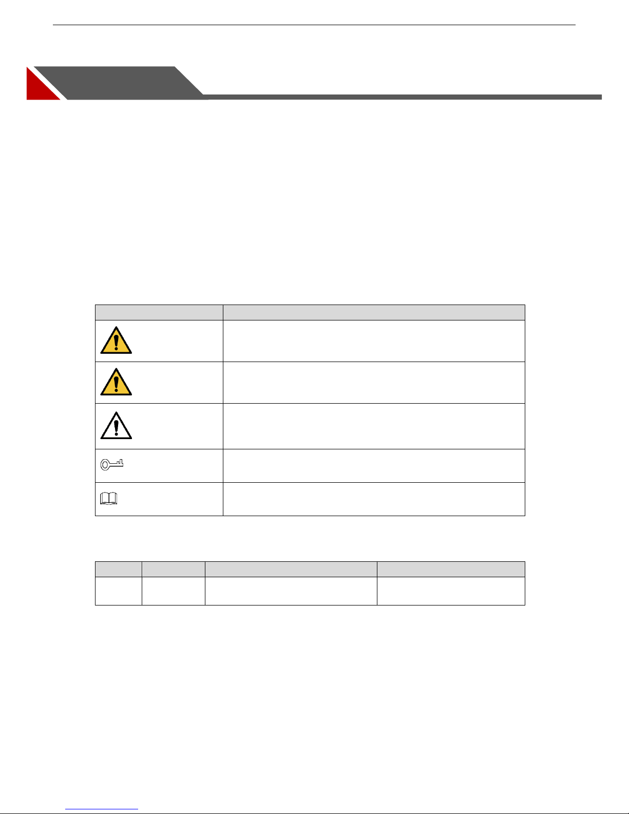
The following categorized signal words with defined meaning might appear in the Manual.
Signal Words
Meaning
DANGER
Indicates a high potential hazard which, if not avoided, will result in
death or serious injury.
WARNING
Indicates a medium or low potential hazard which, if not avoided,
could result in slight or moderate injury.
CAUTION
Indicates a potential risk which, if not avoided, could result in
property damage, data loss, lower performance, or unpredictable
result.
TIPS
Provides methods to help you solve a problem or save your time.
NOTE
Provides additional information as the emphasis and supplement to
the text.
Revision History
No.
Version
Revision Content
Release Time
1
V1.0.0
First Release.
September 21, 2018
Privacy Protection Notice
As the device user or data controller, you might collect personal data of others such as face, fingerprints,
car plate number, Email address, phone number, GPS and so on. You need to be in compliance with the
local privacy protection laws and regulations to protect the legitimate rights and interests of other people by
implementing measures include but not limited to: providing clear and visible identification to inform data
subject the existence of surveillance Area and providing related contact.
Page 4

Alarm Control Panel User Manual
3
About the Manual
The Manual is for reference only. If there is inconsistency between the Manual and the actual product,
the actual product shall prevail.
We are not liable for any loss caused by the operations that do not comply with the Manual.
The Manual would be updated according to the latest laws and regulations of related regions. For
detailed information, see the paper manual, CD-ROM, QR code or our official website. If there is
inconsistency between paper manual and the electronic version, the electronic version shall prevail.
All the designs and software are subject to change without prior written notice. The product updates
might cause some differences between the actual product and the Manual. Please contact the
customer service for the latest program and supplementary documentation.
There still might be deviation in technical data, functions and operations description, or errors in print.
If there is any doubt or dispute, please refer to our final explanation.
Upgrade the reader software or try other mainstream reader software if the Manual (in PDF format)
cannot be opened.
All trademarks, registered trademarks and the company names in the Manual are the properties of
their respective owners.
Please visit our website, contact the supplier or customer service if there is any problem occurred
when using the device.
If there is any uncertainty or controversy, please refer to our final explanation.
Default Access Codes
Supervisor User: 1234
TECHNICIAN: 1961
Page 5

Alarm Control Panel User Manual
4
Important Safeguards and Warnings
This Chapter describes the contents covering proper handling of the Device, hazard prevention, and
prevention of property damage. Read these contents carefully before using the Device, comply with them
when using, and keep it well for future reference.
Operation Requirement
Modify the default access codes after installation to avoid being stolen.
Do not place or install the product in a place exposed to sunlight or near the heat source.
Keep the product away from dampness, dust or soot.
Keep the product installed on the stable place to prevent it from falling.
Do not drop or splash liquid onto the product, and make sure there is no object filled with liquid on the
product to prevent liquid from flowing into the product.
Operate the device within the rated range of power input and output.
Do not dissemble the Device randomly.
Transport, use and store the Device under the allowed humidity and temperature conditions.
Electrical Safety
Use the battery as required; otherwise there might result in fire, explosion, or inflammation.
When replacing battery, make sure the same type is used.
Use the recommended power cables in the region and conform to the rated power specification.
The power source shall conform to the requirement of the Safety Extra Low Voltage (SELV) standard,
and supply power with rated voltage which conforms to Limited power Source requirement according
to IEC60950-1. Please note that the power supply requirement is subject to the device label.
Connect the device (I-type structure) to the power socket with protective earthing.
The appliance coupler is a disconnection device. When using the coupler, keep the angle for easy
operation.
Page 6

Alarm Control Panel User Manual
5
Table of Contents
Cybersecurity Recommendations .............................................................................................................................. 1
Foreword ....................................................................................................................................................................... 2
Important Safeguards and Warnings ......................................................................................................................... 4
1 Introduction ............................................................................................................................................................... 7
Overview ........................................................................................................................................................... 7 1.1
Features ............................................................................................................................................................ 7 1.2
Terms and Definitions ....................................................................................................................................... 8 1.3
2 About the Keypad ...................................................................................................................................................... 9
Dimension ......................................................................................................................................................... 9 2.1
The Grand Tour ............................................................................................................................................... 10 2.2
The Keys ......................................................................................................................................................... 10 2.3
2.3.1 Numeric Keys (0 to 9) ........................................................................................................................... 11
2.3.2 Other Function Keys ............................................................................................................................. 11
2.3.3 Key Combination Operations ............................................................................................................... 12
LED Indicators ................................................................................................................................................ 13 2.4
2.4.1 Overview ............................................................................................................................................... 13
2.4.2 Status .................................................................................................................................................... 14
Main Interface of LCD Display ........................................................................................................................ 15 2.5
Installation ....................................................................................................................................................... 17 2.6
3 Arming and Disarming ............................................................................................................................................ 18
Arming ............................................................................................................................................................. 18
3.1
3.1.1 Total Arming .......................................................................................................................................... 18
3.1.2 Partition 1 Arming ................................................................................................................................. 19
3.1.3 Partition 2 Arming ................................................................................................................................. 20
3.1.4 Partition 1+2 Arming ............................................................................................................................. 21
3.1.5 Forced Arming ...................................................................................................................................... 21
3.1.6 Rapid Arming ........................................................................................................................................ 22
3.1.7 Arming through Timer ........................................................................................................................... 22
3.1.8 Arming from Remote ............................................................................................................................. 22
Disarming ........................................................................................................................................................ 23 3.2
3.2.1 Total Disarming from the Keypad ......................................................................................................... 23
3.2.2 Total Disarming with the Timer ............................................................................................................. 23
3.2.3 Total Disarming through Telephone or SMS ......................................................................................... 23
3.2.4 Disarming under Duress ....................................................................................................................... 23
4 User Menu ................................................................................................................................................................ 24
ZONE TROUBLES .......................................................................................................................................... 24 4.1
SYSTEM TROUBLES ..................................................................................................................................... 26 4.2
ZONE MANAGER ........................................................................................................................................... 27 4.3
LOGBOOK EVENT ......................................................................................................................................... 28 4.4
CHIME ZONES ............................................................................................................................................... 28 4.5
ACCESS CODES ............................................................................................................................................ 29 4.6
4.6.1 Authority Level ...................................................................................................................................... 29
Page 7

Alarm Control Panel User Manual
6
4.6.2 Configuring Authority Level .................................................................................................................. 30
4.6.3 Configuring Access Code ..................................................................................................................... 32
TECHNICIAN .................................................................................................................................................. 33
4.7
FIRMWARE VERSION ................................................................................................................................... 33 4.8
WALK TEST .................................................................................................................................................... 34 4.9
SYSTEM TIMERS ......................................................................................................................................... 35 4.10
DATE/TIME ................................................................................................................................................... 36 4.11
HOLIDAY ....................................................................................................................................................... 37 4.12
TEL NUMBER ............................................................................................................................................... 38 4.13
REMOTE SERVICE ...................................................................................................................................... 40 4.14
SECURITY CODE ........................................................................................................................................ 41 4.15
Technical Specification ......................................................................................................................... 42 Appendix 1
Keypad Buzzer Sound........................................................................................................................... 44 Appendix 2
Event Log Messages ............................................................................................................................. 45 Appendix 3
User Menu Map ...................................................................................................................................... 46 Appendix 4
FAQ.......................................................................................................................................................... 48 Appendix 5
Page 8

Alarm Control Panel User Manual
7
1 Introduction
Overview 1.1
The product is the high performance anti-theft controller designed for the middle and small alarm solution
application. Adopting embedded Linux operation system and relying on embedded platform, the system
can run steadily with advanced controlling technology and strong data transmission ability. The embedded
design also supports the product with high security and excellent stability.
The product can work both independently and with professional app in mobile phone, which is convenient
for remote viewing and alarm status controlling. The product can also be connected to the network to form
the strong security monitoring network, working with the professional alarm platform software to show the
strong networking and remote monitoring ability.
The product can be widely applied in the store, warehouse, family, and so on for security protection.
Features 1.2
The functions might be different depending on the software and hardware version of the model you
purchased.
8 onboard wired Zones.
3 programmable hardware outputs on the Control Panel mainboard, including 1-relay output used as
siren output and 2-mos transistor outputs of OC type.
Outputs operation follows system events, Zone events, Area, Link and scheduling programs.
1 Alarm Control Panel case tamper and 1 leave-wall tamper.
1 siren tamper input.
Up to 8 Areas, and every Area with 2 partitions.
Up to 8 Keypads.
Up to 100 users with 8 authority levels for different users (Supervisor, Manager, Master, User,
Temporary, Duress, Patrol, and Technician).
1000 events log.
Supports more than 11 Zone types.
7 sorts of Zone terminations, including closed-circuit (NC), open-circuit (NO), end-of-line (EOL)
resistors, double end-of-line (DEOL) resistors, triple end-of-line (3DEOL) resistors, inertial type for
vibration detector and pulse type for roller shutter.
Configurable Zone resistance (2K7, 4K7, and 6K8).
With 2 RS-485 ports for Keypads connection and extended connections.
With PSTN port for alarm event report function, supporting CID (Contact ID).
3 telephone numbers for monitor station (PSTN), 8 telephone numbers for vocal message, and 8
telephone numbers for SMS.
With GSM/GPRS network ports for events SMS reporting and remote control, events vocal message
reporting by dialing and remote control, and mobile phone app connection ability when Ethernet
connection is failed.
With 10/100M self-adaptive Ethernet port.
Page 9
Alarm Control Panel User Manual
8
Supports abnormality alarm, including network disconnected alarm, PSTN fault alarm, tampering
alarm, low battery alarm, battery loss alarm, power loss alarm, and keyboard faults alarm.
In-field firmware upgradable.
App-based system control through DMSS.
Terms and Definitions 1.3
Refer to the terms and definitions that are used in the Manual as below.
Table 1-1 Terms and definitions
Term
Definition
Area
The 8 Areas that can be armed.
Zone
Protection zones under Area.
Partition
The scope of Partition is larger than Zone and under Area.
Numeric key
Key 0–9 on the Keypad.
Function key
The other keys except Numeric keys, such as ESC and ENTER.
Key combination
+ Numeric key.
User Menu
Menus programmed by the User.
Installer Menu
Menus programmed by the TECHNICIAN.
Access Code
A specified code, from 4 to 6 digits, that allows the user to operate the
Keypad.
TECHNICIAN
A person that is authorized to access the Installer Menu to program the
system.
Page 10
Alarm Control Panel User Manual
9
2 About the Keypad
This chapter introduces the dimension, main functions, indicators, keys operations, and installation of the
Keypad.
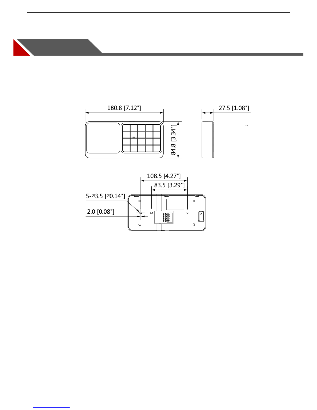
Dimension 2.1
Dimension (mm [inch]) Figure 2-1
Page 11

Alarm Control Panel User Manual
10
The Grand Tour 2.2
Grand tour Figure 2-2
Table 2-1 Functions introduction
No.
Name
Function
1
LCD display
Show all the system information including management and
programming. For details, see "2.5 Main Interface of LCD Display."
LED indicators
Give information about power status, battery status, failures, bypass,
and alarm status of each Area. For details, see "2.4 LED Indicators."
2
The keys
The Keypad keys can do numerous functions. Each key has specific
function. For details, see "2.3 The Keys."
3
Ports
+12V: Supplies 12V DC.
GND: Ground.
RS485_A1
RS485_B1
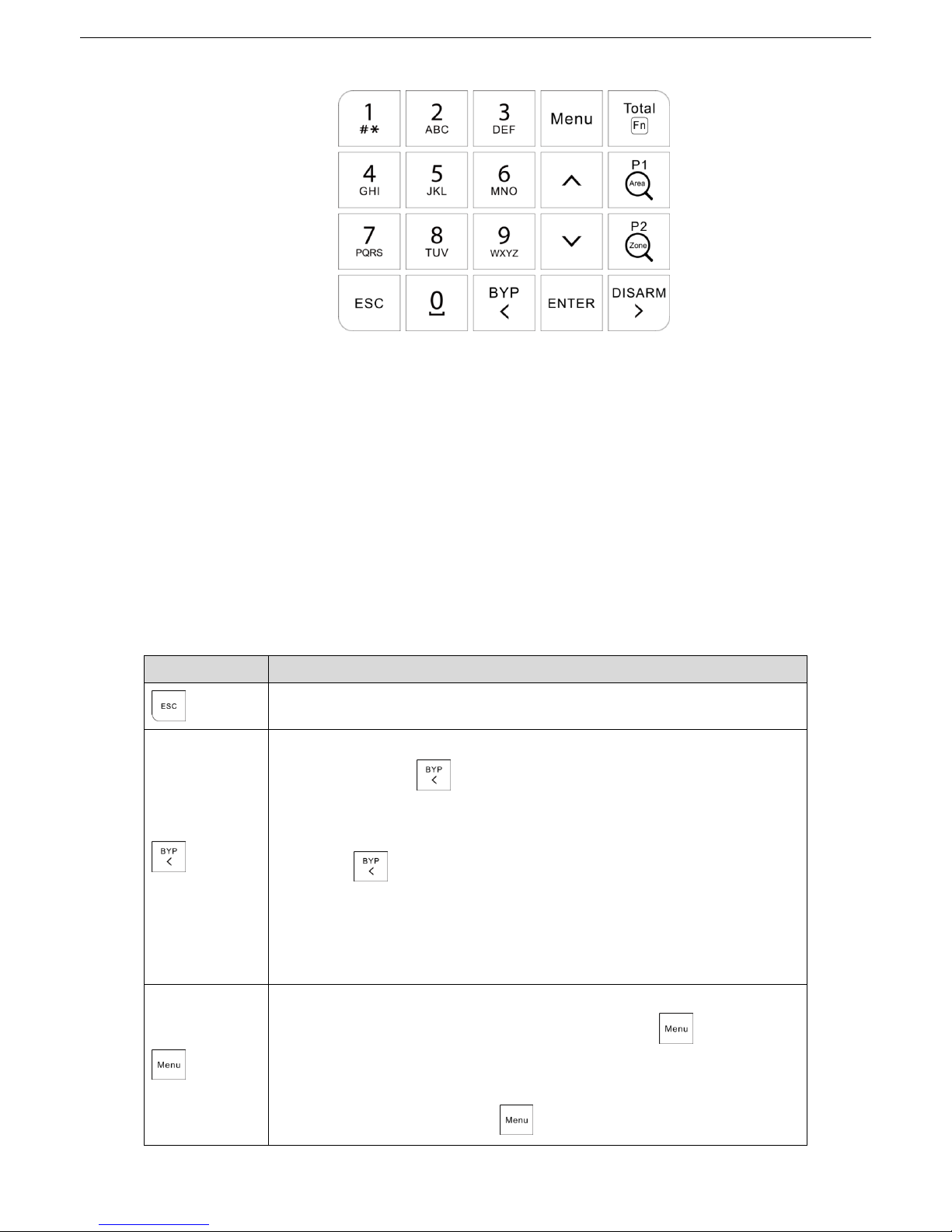
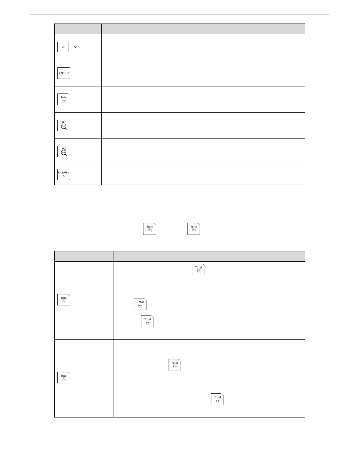
The Keys 2.3
The Keypad keys can do numerous functions. Each key has a specific function as explained below.
Page 12
Alarm Control Panel User Manual
11
The keys Figure 2-3
2.3.1 Numeric Keys (0 to 9)
The numeric keys give the functions as below:
Type in access codes as required to access programming (TECHNICIAN or user) or to arm/disarm.
The keys from 1 to 8 represent eight zones. When the zone is not ready, you can press and hold the
key to show the NOT READY details, and when the key LED light slowly flashes or quickly flashes,
press and hold the key to show the alarm details.
The keys from 0 to 8 can be used to type in or edit alphanumeric descriptions.
Press 1 to type in "#", "*", and ".". Press 0 to type in space.
2.3.2 Other Function Keys
Table 2-2 Other function keys
Key
Function
Exit from the current menu or return to the previous menu.
Move the pointer to the left when you edit.
Press and hold to delete text.
Bypass the Zones as below:
1. Type in the access code.
2. Press . The interface for setting the bypass Zones is shown.
3. Press the corresponding numeric key of the Zones that you want to
bypass. For example, if you want to bypass Zone 12, press Key 1 and
then press Key 2.
4. Press Enter to confirm the setting.
Enter the User Menu or the Installer Menu.
Quick input. For example, if your type in 130, press immediately to
confirm the input; otherwise the input will become invalid.
Quick jump. For example, if you want to view the 200th
log from 300 logs,
type in 200, and then press to jump to the 200th log page.
Page 13
Alarm Control Panel User Manual
12
Key
Function
Increase or decrease numbers.
Switch options on the interface.
Page turning.
Enter the sub menu.
Switch to the next menu of the same level in editing mode.
Confirm the input.
Arm the whole Area.
Rapid Total Arming to the whole Area.
Give combination operations. For details, see Table 2-3.
Arm the PARTITION 1.
Rapid Arming the PARTITION 1.
Give combination operations. For details, see Table 2-3.
Arm the PARTITION 2.
Rapid Arming the PARTITION 2.
Give combination operations. For details, see Table 2-3.
Disarm.
Move the pointer to the right when you edit number or letter.
2.3.3 Key Combination Operations
How to press key combination: Press in sequence.
For example, if you need to press + 0, press first, and then press 0.
Table 2-3 Key combinations
Key
Function
+ 0 (F0)
On the main interface, press + 0 (F0) to show the GSM and
wireless signal strength. The GSM signal is shown with eight bars, and
the wireless signal is shown with four bars.
Press + 0 (F0) again to return to the main interface. Without
pressing + 0 (F0), the system automatically returns to the main
interface in 2 min.
+ 1 (F1)
Panic Activation (silent activation or with sirens and Keypad buzzer)
On the menu of ZONE TROUBLES, ZONE MANAGER, and CHIME
ZONES, press + 1 (F1) to show the Area selection interface
where can select the Areas within which to do the searching and
filtering.
On the OUTPUTS menu, press + 1 (F1) to do a test to the
output circuit, and Active is shown.
Page 14
Alarm Control Panel User Manual
13
Key
Function
+ 2 (F2)
Robbery Activation (silent activation)
There is no response on the interface but this event is recorded in the
log.
On the menu of ZONE TROUBLES, ZONE MANAGER, and CHIME
ZONES, you can select the Zone on which you can do the searching
and filtering.
Edit text on the interfaces such as description of module, zone, user
code, output, timer and display.
Edit telephone number, SMS number, and SIM number on the TEL
NUMBER menu, and PSTN number on MONITOR STATION menu..
+ 3 (F3)
Medical Activation (with Keypad buzzer)
On the WALK TEST menu, switch between individual test and
multiple test.
On the TEL NUMBER menu, start a phone call test or message test.
+ 4 (F4)
Fire Alarm Activation (with Keypad buzzer and siren)
On the TEL NUMBER menu, stop a phone call test.
+ (1–8)
Query which zones under the specified Area.
+ (1–99)
Query which Areas the specified zone belongs to.
LED Indicators 2.4
There are 12 LED indicators on the Keypad that respectively gives information about power status, battery
status, faults, bypass, and alarm status of each Area.
2.4.1 Overview
The Table 2-4 shows the icon, color, and meaning of each LED indicator.
Table 2-4 LED indicators overview
Icon
Color
Meaning
Green
Power status
Green
Battery status
Red
Fault status
Green
Bypass
Red
Alarm status of eight Areas
Page 15
Alarm Control Panel User Manual
14
2.4.2 Status
Power LED Indicator ( )
Glows: The system operates with normal power supply.
Slowly flashes: The system does not operate normally due to a lack of power supply, and therefore a
check must be given.
Quickly flashes: The system is in installer programming mode or on the Walk Test Zone mode. If a
lack of power supply occurs when the system is in either of these two modes, the LED indicator also
quickly flashes.
Battery LED Indicator ( )
Slowly flashes: Battery defects such as low power and powering off quickly.
Off: Battery operates normally.
Fault LED Indicator ( )
Glows: System faults (main power loss, battery low voltage or missing), and you can view the details
on the SYSTEM TROUBLES menu.
Slowly flashes: Tampering is happening to the Control Panel, siren, or Keypad.
Off: The system operates normally.
Bypass LED Indicator ( )
Glows: There is at least one bypassed zone.
Off: There is no bypassed zone.
1-8 LED Indicators
There are eight LED indicators located below the LCD display represent the status of the Areas. From left
to right they show the alarm status of Area 1 to Area 8. See Figure 2-4.
Area status LED indicators Figure 2-4
Glows: The Area is armed.
Slowly flashes: The alarm is in progress or the alarm has occurred
Quickly flashes: The Area is in alarm condition and the linkage is in progress. This condition
disappears when the Area is disarmed. The indicator starts to flash slowly and is cancelled when a
valid user code is typed in again followed by the command DISARMED.
Off: The Area is disarmed.
By pressing and holding the number key corresponding to each Area for three seconds, you can view
where exactly the alarm is in the Area. For example, when the Area 5 indicator quickly flashes, press and
Page 16

Alarm Control Panel User Manual
15
hold Key 5, then * shows where the alarm is located exactly. This operation can only view the Zone-related
alarms, but cannot view the system faults alarms.
Main Interface of LCD Display 2.5
The Keypad is equipped with a back-lit LCD display that shows all the system information including
management and programming.
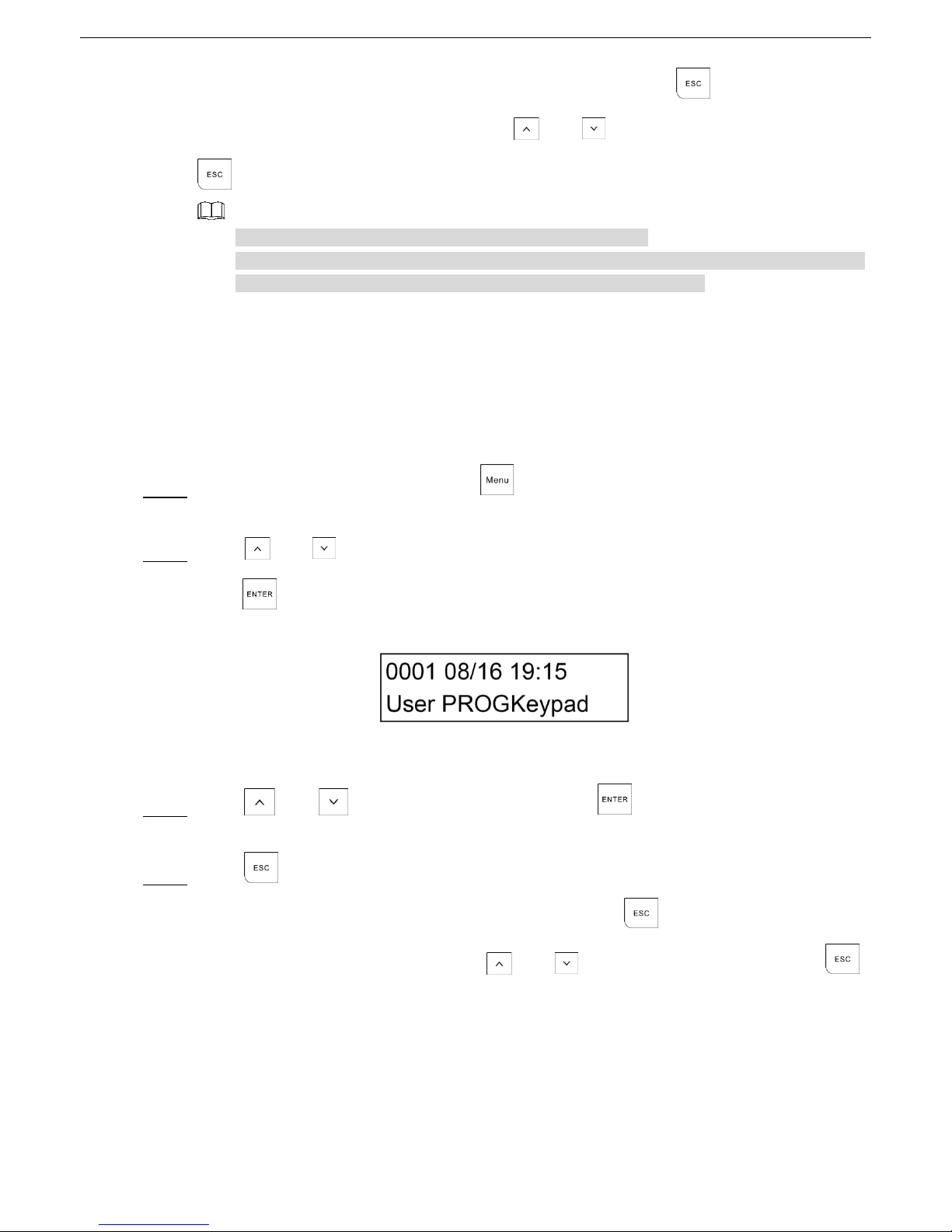
When the display is off and everything is working properly, the first line shows the date and time, and the
second line contains a series of data that represent Area in use in the system.
Example of Keypad with 8 Areas assigned Figure 2-5
Each dash can represent a different meaning according to the event activated by the Area. Refer to
Table 2-6 for the event description and symbol of each event.
Symbols on the First Line of Display
Table 2-5 Symbols on the first line of display
Symbol
Meaning
01/01/03
Day/Month/Year
x
H: Holiday period active
T: Telephone dialer calling
P: Disarming period for Patrol user
00:00
Hour : Minutes
Level of GSM signal. Each is equivalent to one bar, and maximum
eight bars.
Symbols on the Second Line of Display
Table 2-6 Symbols on the second line of display
Symbol
Event
Upper case T
Total Arming
1
Partition Arming 1
2
Partition Arming 2
Upper case P
Partition 1 + Partition 2 arming
Lower case t
Total Forced Arming
Upper case A
Alarm
Entry delay time
Page 17

Alarm Control Panel User Manual
16
Symbol
Event
Exit delay time
*
Area not ready (Zones open)
!
Alarm delay
Alarm Message Display
During an alarm, the main interface shows the general reason description for the alarm in the first line, for
example, ZONE ALARM. The alarm message remains displayed for the entire duration of the alarm.
To verify the event that caused the alarm, you can press and hold the corresponding numeric key (from 1 to
8) to show the event details. The display will show the Zone or the event that triggered the alarm.
To examine whether any other Zones are involved in the alarm, press and to scroll up and down
the page. Normally, the display shows the last Zone affected by the event.
At this moment, if there is a telephone call in progress, when you type in the user code and then press
, the display shows the question: . Press again to confirm the stopping of
telephone call, or press to return to the main interface and not to stop telephone call.
Display of GSM Signal Strength
By pressing + 0 (F0), the display shows the value of GSM signal strength in the first line of main
interface. The value persists for about two minutes, or you can press + 0 (F0) again to exit. You can
also monitor the GSM signal strength during a call in progress.
None : No GSM signal.
One : Minimum GSM signal
Eight : Maximum GSM signal
Page 18

Alarm Control Panel User Manual
17
Installation 2.6
Keypad installation Figure 2-6
Loosen the screws on the back of Keypad to remove the rear panel. Step 1
Pull the cables out of the rear panel.
Step 2
Drill a hole on the wall①, and put the expansion bolt② through the rear panel to fix it onto the wall. Step 3
Put the self-tapping screws④ into the other installation holes on the rear panel③ and then fasten Step 4
screws.
Connect the cables to the ports on the main board. Step 5
Align the clamps on the top of main board with the ones on the rear panel⑤, and then slowly attach Step 6
the main board to the rear panel. The installation is completed⑥.
Page 19

Alarm Control Panel User Manual
18
3 Arming and Disarming
Arming 3.1
When you arm the system, the detectors that are connected to it are activated. If any alarm event occurs,
the detectors give an alarm.
The functions provided by the key combinations for Robbery, Panic, Medical, and Fire are always active
even though the system is disarmed (if enabled by the TECHNICIAN).
The system has the types of arming as below:
Total Arming
Partition 1 Arming
Partition 2 Arming
Partition 1+2 Arming
Forced Arming
Rapid Arming
Arming through Timer
Arming from dialing or SMS
3.1.1 Total Arming
Total Arming activates protection to the entire alarm system and used when there are no persons inside the
Premise.
From total arming, you can only proceed to disarming.
To use the Total Arming, do the following:
Confirm that all Zones are ready to be armed, which means there must not be any * character in Step 1
the place of dash in the second line of the LCD display.
To identify which Zone is not ready, do the following:
1) Press and hold the numeric key (from 1 to 8) where the * character appears.
The first OPEN Zone shows on the display.
2) Press and to scroll up and down the page to show other not ready Zones.
After these Zones are identified, you can send a person to do the onsite examination or go to
ZONE MANAGER menu to set bypass for these Zones.
Enter your user code, and then press . Step 2
The numbers of Areas ready for arming are shown on the second line of the LCD display.
Select the Areas that need to be involved in the arming by pressing the corresponding numeric key Step 3
(from 1 to 8).
Page 20

Alarm Control Panel User Manual
19
Press to do the arming. Step 4
The Keypad emits a confirmation buzzer.
The armed Area shows an upper case T, and the corresponding LED indicator lights up. The Areas
that are not armed continues to show a dash. You can add other Areas to the arming at any time.
See Figure 3-1.
If the Exit Delay is active, the Keypad keeps sounding a buzzer for the entire programmed Exit
Delay period.
Total arming Figure 3-1
3.1.2 Partition 1 Arming
Partition Arming 1 activates partial protection with part of system armed and only activates a predefined
group of detectors.
From Partition Arming 1, you can only proceed to Partition Arming 1+Partition Arming 2, or Total Arming.
To use the Partition Arming 1, do the following:
Confirm that all Zones are ready to be armed, which means there must not be any * character in Step 1
the place of dash in the second line of the LCD display.
To identify which Zone is not ready, do the following:
1) Press and hold the numeric key (from 1 to 8) where the * character appears.
The first OPEN Zone shows on the display.
2) Press and to scroll up and down the page to show other not ready Zones.
After these Zones are identified, you can send person to do the onsite examination or go to
ZONE MANAGER menu to set bypass for these Zones.
Enter your user code, and then press . Step 2
The numbers of Areas ready for arming are shown on the second line of the LCD display.
Select the Areas that need to be involved in the arming by pressing the corresponding numeric key Step 3
(from 1 to 8).
Press to do the arming. Step 4
The Keypad emits a confirmation buzzer.
The armed Area shows the number 1, See Figure 3-2, and the corresponding LED indicator lights
up. The Areas that are not armed continues to show a dash. You can add other Areas to the arming
at any time.
Page 21

Alarm Control Panel User Manual
20
If the Exit Delay is active, the Keypad keeps sounding a buzzer for the entire programmed Exit
Delay period.
Partition arming 1 Figure 3-2
The Areas can be armed in different and mixed modes, for example, you can have two Areas have Total
Arming mode, and two have Partition Arming 1.
Mixed arming 1 Figure 3-3
3.1.3 Partition 2 Arming
Partition Arming 2 activates partial protection with part of system armed and only activates a predefined
group of detectors. To use the Partition Arming 2, do the following:
From Partition Arming 1, you can only proceed to Partition Arming 1+Partition Arming 2, or Total Arming.
Confirm that all Zones are ready to be armed, which means there must not be any * character in Step 1
the place of dash in the second line of the LCD display.
To identify which Zone is not ready, do the following:
1) Press and hold the numeric key (from 1 to 8) where the * character appears.
The first OPEN Zone shows on the display.
2) Press and to scroll up and down the page to show other not ready Zones.
After these Zones are identified, you can send person to do the onsite examination or go to
ZONE MANAGER menu to set bypass for these Zones.
Enter your user code, and then press . Step 2
The numbers of Areas ready for arming are shown on the second line of the LCD display.
Select the Areas that need to be involved in the arming by pressing the corresponding numeric key Step 3
(from 1 to 8).
Press to do the arming. Step 4
The Keypad emits a confirmation buzzer. The armed Area shows the number 2, See Figure 3-2,
and the corresponding LED indicator lights up. The Areas that are not armed continues to show a
dash. You can add other Areas to the arming at any time.
If the Exit Delay is active, the Keypad keeps sounding a buzzer for the entire programmed Exit
Delay period.
Page 22

Alarm Control Panel User Manual
21
Partition arming 2 Figure 3-4
The Areas can be armed in different and mixed modes, for example, you can have two Areas have Total
Arming mode, and two Areas have Partition Arming 2 mode. See Figure 3-5.
Mixed arming 2 Figure 3-5
3.1.4 Partition 1+2 Arming
Partition Arming 1 + Partition Arming 2 activates partial protection with part of system armed and only
activates the detectors that belong to these two Partitions.
From Partition Arming 1 + Partition Arming 2, you can only proceed to Total Arming of an Area.
To perform Partition Arming 1 + Partition Arming 2, you should arm one of the two Partitions with the other
is already armed (the order does not matter). For the arming procedures of Partition Arming, see "3.1.2
Partition 1 Arming" and "3.1.3 Partition 2 Arming."
After the arming operation is completed, the armed Area shows the upper case P. See Figure 3-6.
Partition arming 1 and Partition arming 2 Figure 3-6
The Areas can be armed in different and mixed modes, for example, you can have one Partition Arming 1,
one Partition Arming 2, and one Total Arming mode. See Figure 3-5.
Mixed arming Figure 3-7
3.1.5 Forced Arming
Forced Arming allows you to override not ready system arming caused by open Zones, without any
additional operations. This type of arming can be useful when the open or not ready Zones are windows or
doors whose status you know and that you wish to leave open. Another instance where Forced arming is
useful is when one or more sensors are in a TROUBLE condition but you do not want to put them into
bypassed status.
In order for an access code to be able to provide Forced Arming, you must have the relevant attribute
programmed, for details, see "4.6 ACCESS CODES" menu.
Page 23

Alarm Control Panel User Manual
22
After the Forced Arming has been set, the bypass LED indicator lights up showing that some detectors are
automatically bypassed. If the Forced Arming is set for the whole Area, a lower case t is shown on the LCD
display, see Figure 3-8.
The Forced Arming could inhibit sensors that you DID NOT wish to bypass from arming without your
realizing it.
After disarming, all the detectors involved in the Forced Arming will become available for arming again.
Forced arming Figure 3-8
3.1.6 Rapid Arming
Rapid Arming allows you to Arm the alarm system without entering the user code. The only difference
between Rapid Arming and arming with the code is the practicality of performing the operation quickly. To
Disarm the system, you must type in a valid code.
Preparation
To use the Rapid Arming, the TECHNICIAN must have programmed the Keypad. Otherwise, the Keypad
cannot do the Rapid Arming.
Procedure
To do the Rapid Arming, press and hold for the arming that you require on the Areas that belong to
the Keypad.
You can also arm the system with IMMEDIATE or DELAYED exit time for Rapid Arming if this is
programmed by the TECHNICIAN.
To disarm from Rapid Arming, you need to type in a valid user code.
3.1.7 Arming through Timer
You can arm the alarm system by timer that is set on the SYSTEM TIMER menu.
This setting can be managed and programed by the TECHNICIAN, Supervisor, and Manager. For details,
see "4.10 SYSTEM TIMERS" menu.
The system also supports programming HOLIDAYS during which the TIMER will not have any effect. For
details, see "4.12 HOLIDAY" menu.
3.1.8 Arming from Remote
The alarm system can also be armed from telephone through a specific procedure with an interactive vocal
guide or through SMS messages.
Page 24

Alarm Control Panel User Manual
23
Disarming 3.2
When you disarm the system, all the connected detectors are deactivated.
The system has the types of arming as below:
Total Disarming
Disarming through Timer
Disarming through Telephone or SMS text
Disarming under Duress
3.2.1 Total Disarming from the Keypad
You can do the disarming where there is an alarm or you just want to disarm.
Type in the user code on the Keypad. Step 1
Press . Step 2
The Area that can be disarmed is shown on the LCD display.
Press the corresponding key on the Keypad to the Area that you want to disarm. Step 3
Press to disarm the Area totally. Step 4
3.2.2 Total Disarming with the Timer
You can disarm the alarm system by timer that is set on the SYSTEM TIMER menu.
This setting can be managed and programed by the TECHNICIAN and Supervisor user. For details, see
"4.10 SYSTEM TIMERS" menu.
The system also supports programming HOLIDAYS during which the TIMER will not have any effect. For
details, see "4.12 HOLIDAY" menu.
3.2.3 Total Disarming through Telephone or SMS
The alarm system can also be disarmed from telephone through a specific procedure with an interactive
vocal guide or through SMS text messages.
3.2.4 Disarming under Duress
You can do the disarming with a changed use code or a specific duress code to give an duress alarm. Take
the normal use code is 1234 as an example. You can increase or decrease the last figure.
Type in the changed user code, for example, 1235. Step 1
Press . Step 2
The Area that can be disarmed is shown on the LCD display.
Press the corresponding key on the Keypad to the Area that you want to disarm. Step 3
Press to disarm the Area totally. Step 4
Page 25

Alarm Control Panel User Manual
24
4 User Menu
This Chapter describes the operations included in the User Menu.
The User Menu consists of many menus for management and programming operations as below:
ZONE TROUBLES
SYSTEM TROUBLES
ZONES MANAGER
LOGBOOK EVENT
CHIME ZONES
ACCESS CODES
TECHNICIAN
FIRMWARE VERSION
WALK TEST
SYSTEM TIMERS
DATE/TIME
HOLIDAY
TEL NUMBERS
REMOTE SERVICE
SECURITY CODE
To enter the User Menu, you need an access code. So the User Menu is accessible from the codes that
have an appropriate security level. The factory default user code is 1234 that is also the user code of
Supervisor user with the highest authority.
It is possible to scroll through the menus by the up and down arrow keys, or to go directly to the required
menu by pressing the number of the menu + .
To exit from the User Menu, press until the Keypad requests "EXIT FROM MENU?", then press
to confirm or press again to cancel.
ZONE TROUBLES 4.1
The ZONE TROUBLES menu examines which Zones are in NOT READY status and the reason for the
fault, and then judge if it is necessary to close it or bypass it.
Type in the access code, and then press . Step 1
The ZONE TROUBLES menu is shown on the LCD display. See Figure 4-1.
Zone troubles Figure 4-1
Press to enter the menu. Step 2
Page 26
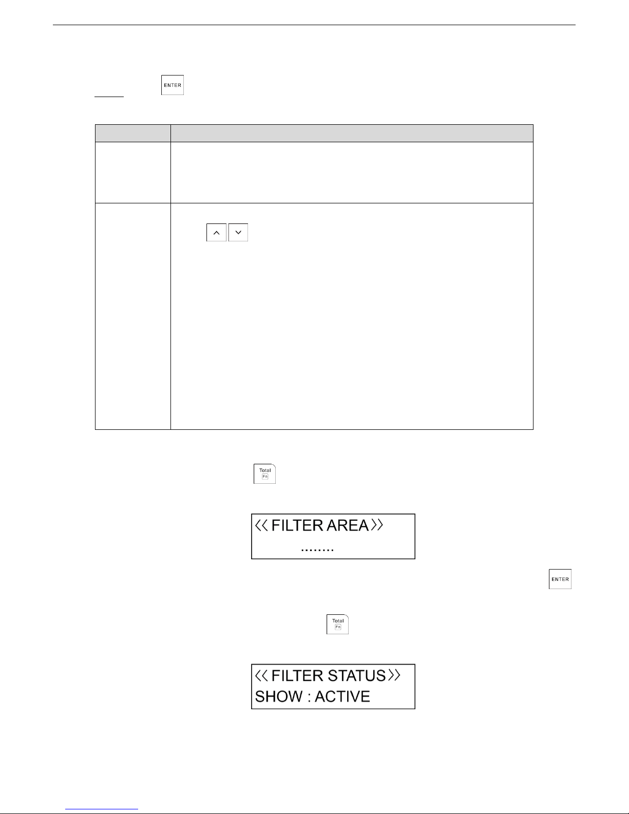
Alarm Control Panel User Manual
25
If there are no fault Zones, the interface shows "NO TROUBLE."
If there are Zones in trouble, there are three categories: TAMPER, SHORT, and MASK.
Press to enter the programming mode. See Table 4-1. Step 3
Table 4-1 Zone troubles programming
Option
Description
Trouble type
Shows type of trouble.
TAMPER: Tampering detectors.
SHORT: Short circuit.
MASK: Anti-shielding.
STATUS
Shows the Zone exclusion mode: ACTIVE, ISOLATE, TEST, and BYPASSED.
Press to select the specific exclusion mode.
A: ACTIVE
The Zone is in normal condition.
I: ISOLATE
The Zone is excluded (removed) permanently and can be brought back
only when switching to ACTIVE.
T: TEST
The Zone is temporarily excluded for a period that is defined by the
TECHNICIAN, and the Zone continues to be part of the armed Zones but
do not generate alarms.
B: BYPASSED
The Zone is temporarily bypassed from arming of the system. The Zone
can be re-armed when the Area is disarmed.
If there are many trouble Zones, you can set a search filter by AREA and ACTIVATION STATUS as
below.
Filter by AREA: Press + 1 (F1). See Figure 4-2.
Filter by Area Figure 4-2
Press the corresponding numeric keys of Areas that you want to search, and then press
to start filtering.
Filter by ACTIVATION STATUS: Press + 2 (F2). See Figure 4-3.
Filter by activation status Figure 4-3
Page 27

Alarm Control Panel User Manual
26
Press and to alter the searching criterion: ALL, BYPASSED, TEST, ISOLATE, and
ACTIVE.
Press to confirm the setting, and then press to return to the ZONE TROUBLES menu. Step 4
Then you can press and to move to the next menu or press to exit from the User
Menu.
SYSTEM TROUBLES 4.2
The SYSTEM TROUBLES menu examines which faults are present in the alarm system. If the Fault LED
indicator glows or flashes, a system fault might be present.
To find what the fault is, you need to enter the SYSTEM TOUBLES menu as below:
Type in the access code, and then press . Step 1
The ZONE TROUBLE menu is shown on the LCD display (Figure 4-1).
Press and to scroll up and down until you reach the SYSTEM TOURBLES menu, and Step 2
then press .
If there are no system faults, see Figure 4-4.
System troubles Figure 4-4
If there are system troubles, which include three categories: TAMPER, TROUBLE, and COM
TROUBLE. See Table 4-2.
Table 4-2 System troubles programming
Option
Description
TAMPER
Panel Tamper
Siren Tamper
Module Tamper
TROUBLE
System date and time
220V AC main supply
Low battery
Battery trouble
PSTN line
GSM line
Antenna fault
SIM expiration
PWD default
COM TROUBLE
Device fault (such as Keypad and module)
Page 28

Alarm Control Panel User Manual
27
Press to confirm the setting, and then press to return to the SYSTEM TROUBLES Step 3
menu.
Then you can press and to move to the next menu or press to exit from the User
Menu.
ZONE MANAGER 4.3
The ZONES MANAGER menu allows any Zone of the system to be placed in BYPASS regardless of its
current status (open or trouble).
Type in the access code, and then press . Step 1
The ZONE TROUBLE menu is shown on the LCD display (Figure 4-1).
Press and to scroll up and down until you reach the ZONE MANAGER menu, and then Step 2
press .
The ZONE MANAGER menu is shown on the LCD display. See Figure 4-5.
Zone manager Figure 4-5
Press and to select the desired Zone, and then press .
Step 3
The submenu for changing status is shown.
Press and to select the status for the desired Zone. Step 4
ACTIVE: The Zone is in normal condition.
ISOLATE: The Zone is excluded permanently and can be brought back only when switching to
ACTIVE.
TEST: The Zone is temporarily excluded for a period that is defined by the TECHNICIAN, and
the Zone continues to be part of the armed Zones but do not generate alarms.
TEST mode is not applicable to the type Entry 1 delay and Entry 2 delay.
BYPASSED: The Zone is temporarily bypassed from arming of the system. The Zone can be
re-armed when the Area is disarmed.
Press to confirm the setting, and then press to return to the wired zones selection Step 5
menu.
Page 29
Alarm Control Panel User Manual
28
Then you can continue with programming other wired zones, or press to return to the ZONE
MANAGER menu from where you can press and to move to the next menu or press
to exit from the User Menu.
Repeat the previous steps to manage other Zones if needed.
If there are many trouble Zones that you want to manage, you can set a search filter by AREA
and ACTIVATION STATUS. For details, see "4.1 ZONE TROUBLES."
LOGBOOK EVENT 4.4
The LOGBOOK EVENT menu contains all the Control Panel events with the respective date and time,
such as alarms, arming and disarming, faults.
The events are shown from the most recent to the oldest, and when the event memory is filled up, the
oldest event makes room for the most recent ones.
Type in the access code, and then press . Step 1
The ZONE TROUBLE menu is shown on the LCD display (Figure 4-1).
Press and to scroll up and down until you reach the LOGBOOK EVENT menu, and then Step 2
press to enter the interface that shows the latest stored event. See Figure 4-6.
The latest stored event Figure 4-6
The first line shows the event with its number and the date and time.
The second line shows the event details.
Press and to select the event, and then press to extend the display to view Step 3
more details of the event.
Press to return to the log event selection menu. Step 4
Then you can continue with viewing other log events, or press to return to the LOGBOOK
EVENT menu from where you can press and to move to the next menu or press
to exit from the User Menu.
CHIME ZONES 4.5
The CHIME ZONES menu is useful for obtaining a Keypad buzzer sound whenever a specific Zone is
affected while the system is disarmed. This function is particularly useful for monitoring the presence of
persons in particular Zones or the opening of a door or window.
Page 30
Alarm Control Panel User Manual
29
The CHIME ZONES menu activates CHIME mode for an individual Zone. In any case, only the Zones
defined by the TECHNICIAN as CHIME Zones can be activated in the CHIME mode.
Type in the access code, and then press . Step 1
The ZONE TROUBLE menu is shown on the LCD display (Figure 4-1).
Press and to scroll up and down until you reach the CHIME ZONES menu, and then Step 2
press .
If the TECHNICIAN did not program any Zone with CHIME mode, the interface shows "NO
FOUND."
If the TECHNICIAN programmed the Zone with CHIME mode, continue the operations.
Press and to select YES or NO. Step 3
Press to confirm the setting, and then press to return to the CHIME ZONES menu. Step 4
Then you can press and to move to the next menu or press to exit from the User
Menu.
Repeat the previous steps to set CHIME mode for other Zones if needed.
If there are many Zones that you want to set CHIME mode, you can set a search filter by
AREA and ACTIVATION STATUS. For details, see "4.1 ZONE TROUBLES."
ACCESS CODES 4.6
The ACCESS CODES menu allows you to customize the user codes for accessing the Control Panel. Each
user is assigned with a code that is linked with an Authority level. Users with high authority can do most of
operations in the system, and those with low authority are restricted to some operations.
4.6.1 Authority Level
Table 4-3 Authority level
User type
Authority level
Supervisor
All operations on all Areas. Factory default setting is 1234.
Manager
All operations on the Areas allowed by the Keypad. The Manager can
change his own code and those of a lower level, but cannot change the
Supervisor code.
Master
Operations only on the Areas that are assigned to Master. The Master can
only change his own code and those of a lower level and access the User
Menu up to option 9.
User
Operations only on the Areas that are assigned to User. The User can only
change his own code and access the User Menu up to option 9.
Temporary
Valid only for an arming and disarming operation. The Temporary does not
have access to the User Menu.
Page 31
Alarm Control Panel User Manual
30
User type
Authority level
Duress
Valid only for arming and disarming with automatic activation of the duress
output. The Duress does not have access to the User Menu.
Patrol
Valid only for disarming operation. When the patrol time ends, the Zones are
automatically armed again.
4.6.2 Configuring Authority Level
Type in the access code, and then press . Step 1
The ZONE TROUBLE menu is shown on the LCD display (Figure 4-1).
Press and to scroll up and down until you reach the ACCESS CODES menu, and then Step 2
press .
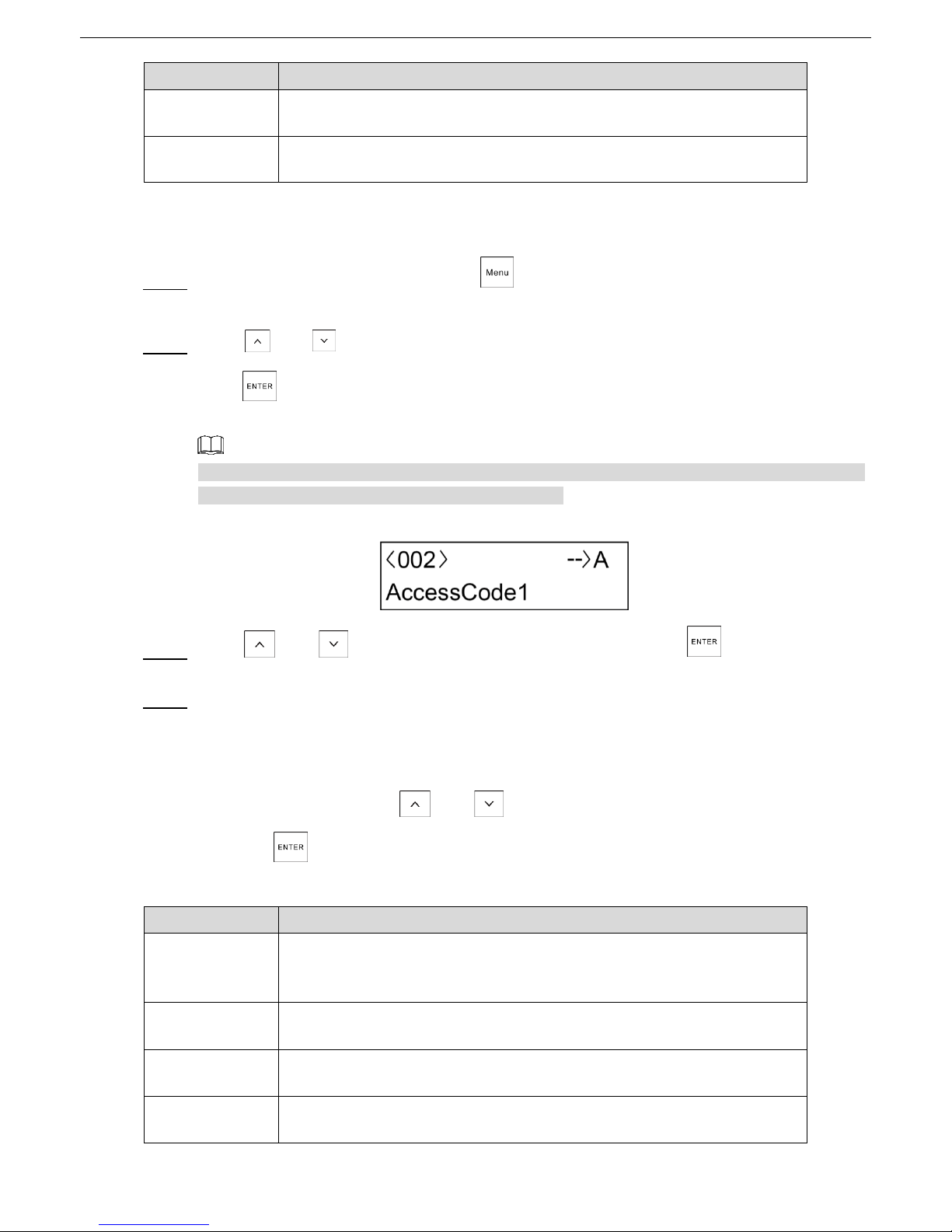
The Access Code 1 submenu is shown. See Figure 4-7.
Access Code 1 is always the Supervisor code. From 2 onwards it is possible to program users with
an authority level. You can set up to 99 access codes.
Access Code 1 Figure 4-7
Press and to select a desired access code, and then press to enter the Step 3
programming mode.
Set the authority parameters. See Table 4-4. Step 4
For Supervisor and Manager, you only need to set STATUS,LEVEL, ARMING, FORCED ARM,
and LINK submenus. For Master, User, Temporary, and Duress, you should set all the
submenus.
In each submenu, press and to alter the options. After setting each submenu,
press to enter the next submenu.
Table 4-4 Access code level and submenus
Submenu
Setting
STATUS
Set the code to an operating or non-operating status.
ACTIVE
ISOLATE
LEVEL
Give an authority level to the user. For the different authority level, see
Table 4-3.
AREAS
Establish on which Areas the access code can operate.
PART1
Establish whether the access code can operate Partition 1 and Partition 2
arming types under the selected Areas.
Page 32

Alarm Control Panel User Manual
31
Submenu
Setting
PART2
ARM
Establish whether the access code has the authority to arm or disarm the
Control Panel.
YES
NO
YES LINK 4: The access code can link the output 4 when arming or
disarming.
DISARM
ARMING
Establish whether the code, when armed, activates the system immediately
or leaving Area exit delays.
IMMEDIATE
DELAYED
FORCED ARM
Establish whether the code can arm the system even with alarm detectors
in a not ready status. For example, windows left open deliberately or
defective sensors.
YES
NO
STOP CALL
Establish whether the access code can answer or stop a telephone call
when there is a telephone call in progress.
YES
NO
ZONE STATUS
Establish whether the access code can change the Zone status, for
example, from ACTIVE to DISALED.
YES
NO
REMOTE
Establish whether the access code can control the Control Panel through
telephone call or SMS.
YES
NO
TIMER
Establish whether the access code is limited to operation only during certain
time period.
There are four TIMERS can be given to the access code, and each TIMER
can select from eight timers that are configured in the system. If you select
0, the access code can operate during the whole period instead of limited
time period.
LINK 1, 2, 3, 4
Establish whether the access code has the authorization to activate
command outputs (maximum 4) and the number of outputs to be activated.
This function is valid only when the Link type is selected in OUTPUT
menu of Installer Menu.
The output to be activated must set the categories item to LINK type by
the TECHNICIAN on the OUTPUTS menu.
NEW CODE
Type in a new code that contains from 4 to 6 digits and cannot start with 0.
For details, see "4.6.3 Configuring Access Code."
Page 33

Alarm Control Panel User Manual
32
Press to confirm all the settings, and then press to return to the access codes Step 5
selection menu.
Then you can continue with programming other access codes, or press to return to the
ACCESS CODES menu from where you can press and to move to the next menu or
press to exit from the User Menu.
4.6.3 Configuring Access Code
Setting an Access Code
If you want to set or change the access code, follow the steps described in "4.6.2 Configuring Authority
Level" to enter the NEW CODE submenu.
On the NEW CODE submenu, type in the new code, and then press . Step 1
The confirmation text "PWD VALID" is shown.
Type in the new code again, and then press to store the new code. Step 2
If the code is not valid or typed incorrectly, the operation will not succeed and two beeps with the
text "PWD INVALID" confirming the error. In this case, repeat the operation correctly.
Press to exit. Step 3
Deleting an Existing Access Code
Access Code 1 cannot be deleted.
On the Access Code submenu, for example, Access Code 2, press and hold for at least Step 1
three seconds.
The "NO PRESENT" message is shown to indicate that the Access Code is deleted.
Press to exit. Step 2
A deleted access code is no longer operational but can be reactivated by a user with an appropriate
authority level such as Supervisor.
Customizing the Description of Access Code
You can customize the factory default description (Access Code no.) if needed.
On the access code submenu (Figure 4-7), press + 2 (F2) to enter the editing status. Step 1
Press and to move to the position of the description, and then insert the character by Step 2
using the specific key (0 to 9).
Page 34
Alarm Control Panel User Manual
33
Press to finish and save the description. Step 3
Press to exit from the submenu or press to continue. Step 4
TECHNICIAN 4.7
The purpose of the TECHINCIAN menu is to authorize the TECHICIAN to access Installer Menu.
Otherwise, the TECHNICIAN cannot make any programming changes to the Control Panel without your
authorization.
In practice, for the TECHINCIAN to be able to access programming, the TECHINCIAN must be authorized
by a valid user code (Temporary, Duress and Patrol are not valid).
The operation is confirmed by three buzzers and makes the TECHINCIAN Code operational and
authorized for a personalized period of hours. The period hours can be set from 1 hour to 10 hours in the
SYSTEM TIMING menu of Installer Menu.
Type in the access code, and then press . Step 1
The ZONE TROUBLE menu is shown on the LCD display (Figure 4-1).
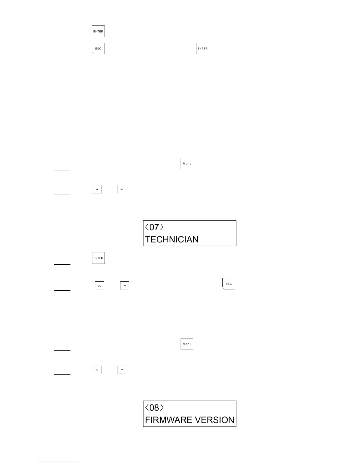
Press and to scroll up and down until you reach the TEHCNICIAN menu, see Step 2
Figure 4-8.
TECHNICIAN menu Figure 4-8
Press . Step 3
Three beeps confirm the TECHNICIAN code operational and authorized for a defined period.
Press and to move to the next menu or press to exit from the User Menu. Step 4
FIRMWARE VERSION 4.8
The FIREWARE VERSION examines the version of software installed in the Control Panel and the Keypad.
If necessary, specify it to your TECHNICIAN. The Control Panel can be updated to more recent versions.
Type in the access code, and then press . Step 1
The ZONE TROUBLE menu is shown on the LCD display (Figure 4-1).
Press and to scroll up and down until you reach the FIRMWARE VERSION menu, see Step 2
Figure 4-9.
Firmware version Figure 4-9
Page 35

Alarm Control Panel User Manual
34
Press to show the Host Version (Control Panel version), and then press again to Step 3
switch to show the Keypad Version.
Press to return to the FIREWARE VERSION menu. Step 4
Then you can press and to move to the next menu or press to exit from the User
Menu.
WALK TEST 4.9
The WALK TEST menu tests the functionality of the installed detectors and examines the response of the
OPEN/CLOSED/TAMPER/FAILURE status to the Control Panel.
Only the Zones with ACTIVE status can be tested.
When the system in the Armed status, entering WALK TEST menu prompts the unauthorized
message.
When one Keypad has entered the Walk Test mode, other Keypads shows "OUT OF USE."
The WALK TEST menu cannot return to the main interface automatically.
Type in the access code, and then press . Step 1
The ZONE TROUBLE menu is shown on the LCD display (Figure 4-1).
Press and to scroll up and down until you reach the WALK TEST menu,see Figure 4-10. Step 2
Walk test Figure 4-10
Press to enter the interface that shows the status of the connected detectors: CLOSED, Step 3
OPEN, TAMPER, SHORT, and MASK. For example, see Figure 4-11.
Test menu Figure 4-11
Press + 3 (F3) to switch between A (multiple test) and B (individual test). Step 4
If you select A, only the Zone triggered is shown.
If you select B, you can press and to select another Zone to be tested.
Press to return to the WALK TEST menu. Step 5
Then you can press and to move to the next menu or press to exit from the User
Menu.
Page 36

Alarm Control Panel User Manual
35
SYSTEM TIMERS 4.10
The SYSTEM TIMERS sets the START and STOP time and days of the week for each Timer.
The SYSTEM TIMERS can be used in other submenu settings named Timer. The Timer can be used for
timed Arming/Disarming of specific Areas, authorizing codes to work within time limits, and timed
activation/deactivation of specific Control Panel outputs.
Type in the access code, and then press . Step 1
The ZONE TROUBLE menu is shown on the LCD display (Figure 4-1).
Press and to scroll up and down until you reach the SYSTEM TIMERS menu, see Step 2
Figure 4-12.
System timer Figure 4-12
Press to enter the submenu from where you can select a desired Timer that you want to set Step 3
(totally eight timers).
By pressing + 2 (F2), you can enter the EDITING mode for changing the description of timer.
Press and to select a timer, and then press to enter the programming mode. Step 4
Configure the Timer settings. See Table 4-5. Step 5
On each submenu, press and to alter the options. After setting each submenu, press
to enter the next submenu.
Table 4-5 Timer settings description
Submenu
Setting
STATUS
ACTIVE: Timer enabled.
ISOLATE: Timer enabled by temporarily locked, but you still can
continue to configure other settings.
OFF: Timer is completely disabled, and you cannot continue the next
pages of settings.
TYPE
START ONLY: Used only for automatic arming operations.
STOP ONLY: Used only for automatic disarming operations.
START/STOP: Used only for both automatic arming and disarming
operations.
START TIME
Type in the start time for automatic arming by pressing the corresponding
keys and then press to confirm the value. You can also press
and to change the value.
Page 37

Alarm Control Panel User Manual
36
Submenu
Setting
STOP TIME
Type in the start time for automatic disarming by pressing the corresponding
keys and then press to confirm the value. You can also press
and to change the value.
DAYS
Select the week days to be active for the Timer.
Press Key 1 to 7 to select the day (M T W T F S S).
HOLIDAYS
Establish whether the timer being programmed refers to the holidays
programmed in "4.12 HOLIDAY."
YES: The timer is blocked during the holiday periods. For example, if
associated with the arming/disarming of Areas, it no longer causes
disarming during the holiday period; if associated to a code, remote
controls or outputs, these will no longer be operative during the holiday
period.
NO: The timer does not follow the holiday conditions, and therefore
continues active whatever is associated with it.
ARMING
Select the type of arming for the Timer.
DELAYED
IMMEDIATE
FORCEDARM
Select whether the Timer arming will be forced.
YES
NO
Press to returns to the Timer selection menu. Step 6
Then you can continue with programming other Timers, or press to return to the SYSTEM
TIMER menu from where you can press and to move to the next menu or press
to exit from the User Menu.
DATE/TIME 4.11
The DATE/TIME menu sets the time of the Control Panel.
Type in the access code, and then press . Step 1
The ZONE TROUBLE menu is shown on the LCD display (Figure 4-1).
Press and to scroll up and down until you reach the DATE/TIME menu, see Figure 4-13. Step 2
Date and time Figure 4-13
Press to enter the programming mode. See Table 4-6. Step 3
Page 38

Alarm Control Panel User Manual
37
Type in the value, press to show the value, then press to confirm the value. You can
also press and to change the value, and press to move to next editing.
Table 4-6 Date and time settings
Submenu
Setting
TIME
Set the time for the Control Panel.
DATE
Set the date for the Control Panel.
SOL TO LEG
Set the day and the month for the automatic change of time from Solar to
Legal.
LEG TO SOL
Set the day and the month for the automatic change of time from Legal to
Solar.
EXPIRY
Set the expiration date of the SIM card (if prepaid) installed in the GSM
telephone communicator.
It is suggested to set a minimum period of 10 days before the real
expiration of the SIM card so as to have adequate warning time to
recharge it and extend its validity.
At the set date, the fault status LED indicator will light up. And if
programmed, SMS messages can be sent to external telephone
numbers.
Press to confirm the setting. Step 4
Press to return to the DATE/TIME menu. Step 5
Then you can press and to move to the next menu or press to exit from the User
Menu.
HOLIDAY 4.12
The HOLIDAY menu sets the holiday dates of the year when the Timers must not affect the system. You
can program up to 20 holidays, and a holiday period can consist of just one day.
Type in the access code, and then press . Step 1
The ZONE TROUBLE menu is shown on the LCD display (Figure 4-1).
Press and to scroll up and down until you reach the HOLIDAY menu, see Figure 4-14. Step 2
Holiday Figure 4-14
Press to enter the submenu from where you can select a Holiday that you want to program. Step 3
Page 39

Alarm Control Panel User Manual
38
By pressing + 2 (F2), you can enter the EDITING mode for changing the description of
holiday.
Press and to select a holiday, and then press to enter the programming mode. Step 4
See Figure 4-15.
Holiday programming Figure 4-15
1: Holiday start day
2: Holiday start month
3: Holiday end day
4: Holiday end month
5: Holiday year
Type in the value, press to show the value, and then press to confirm the value. You Step 5
can also press and to change the value, and then move on to the next field.
Press to confirm the setting. Step 6
Press to returns to the holiday selection menu.
Step 7
Then you can continue with programming other holidays, or press to return to the HOLIDAY
menu from where you can press and to move to the next menu or press to exit
from the User Menu.
To delete a Holiday, on the Holiday selection interface where the Holiday name is shown, press
and hold for at least three seconds.
TEL NUMBER 4.13
The TEL NUMBER menu sets the telephone numbers that will be used by the dialer for voice calls and
SMS. You can program up to 8 different telephone numbers for vocal messages, and 8 numbers for text
SMS. You can also record the SIM card number that is installed in the Control Panel.
Type in the access code, and then press . Step 1
The ZONE TROUBLE menu is shown on the LCD display (Figure 4-1).
Press and to scroll up and down until you reach the TEL NUMBER menu, see Step 2
Figure 4-16.
Page 40

Alarm Control Panel User Manual
39
Telephone number Figure 4-16
Press to enter the interface from where you can select the submenus from TEL NUM, SMS Step 3
NUM, and SIM NUM by pressing and .
Configure the telephone number submenu settings. Step 4
TEL NUM
1) On the TEL NUM submenu, press to enter the interface from where you can select a
telephone number that you want to program by pressing and .
2) After selecting a telephone number, press to enter the programming mode.
3) Configure the telephone number settings. See Table 4-7.
Table 4-7 Telephone number setting
Submenu
Setting
STATUS
ACTIVE: Allow the telephone number to call.
ISOLATE: Do not allow the call in and out of the telephone number.
STOP CYCLE
YES: When the alarm event occurs, if the event is programmed to link
multiple telephone numbers, press # key on your telephone to hang up
the call, the calling will not link to other telephone numbers.
NO: When the alarm event occurs, if the event is programmed to link
multiple telephone numbers, the calling will continue to call other
telephone numbers although pressing # key on your telephone.
Other functions:
Press + 2 (F2) to enter the EDITING mode for changing the telephone number. You
can type in up to a maximum of 24 digits. Use the horizontal cursor keys to move within
the number. Any of the digits can be overwritten. By positioning at any point in the number
(for example, at the start) and holding down , it is possible to delete all the digits from
that point onwards (for example, deletion of the entire number).
Press + 3 (F3) to do a test call on this number.
Press + 4 (F4) to interrupt the call in progress at any time.
4) Press until returns to the start of TEL NUM submenu.
SMS NUM
1) On the SMS NUM submenu, press to enter the interface from where you can select a
telephone number that you want to program by pressing and .
Page 41

Alarm Control Panel User Manual
40
2) After selecting a telephone number, press to enter the programming mode.
3) Configure the SMS number settings. See Table 4-8.
Table 4-8 SMS number setting
Submenu
Setting
STATE
ACTIVE: Allow the text SMS to be sent and received.
ISOLATE: Do not allow the text SMS to be sent and received.
SYSTEM
Press 1 to 7 to select the corresponding week days to send the system
status message to this SMS number.
CREDIT
Press 1 to 7 to select the corresponding week days to send the balance
information of the SIM card that is installed in the Control Panel.
SMS TIME
Type in the specific time for SYSTEM and CREDIT.
AREA
Press 1 to 8 to select the alarm event from which Area can be sent to this
SMS number.
EVENT
Press 1 to 5 to select which event can be sent to this SMS number.
1: S-system event
2: M-module
3: E-Emergency
4: I-Arm/Disarm
5: Z-Zones
4) After completing the settings, press until returns to the start of SMS NUM submenu.
SIM NUM
Record the SIM card number that is installed in the Control Panel.
Press to return to the TEL NUMBER menu. Step 5
Then you can press and to move to the next menu or press to exit from the User
Menu.
REMOTE SERVICE 4.14
The REMOTE SERVICE menu gives possibility to activate the alarm Control Panel remotely by telephone
from the control center of your Installer.
Type in the access code, and then press . Step 1
The ZONE TROUBLE menu is shown on the LCD display (Figure 4-1).
Press and to scroll up and down until you reach the REMOTE SERVICE menu, see Step 2
Figure 4-17.
Remote service Figure 4-17
Page 42

Alarm Control Panel User Manual
41
Press to enter the programing mode. Step 3
On the STATE submenu, select YES or NO.
Step 4
YES: Allows remote control by the Installer from telephone call, SMS, App, or Platform.
NO: Do not allow the remote control by the Installer.
Press to return to the REMOTE SERVICE menu. Step 5
Then you can press and to move to the next menu or press to exit from the User
Menu.
SECURITY CODE 4.15
The SECURITY CODE menu sets the code that is used to protect your alarm Control Panel from
connecting with personal computers locally or remotely of your Installer.
Type in the access code, and then press . Step 1
The ZONE TROUBLE menu is shown on the LCD display (Figure 4-1).
Press and to scroll up and down until you reach the SECURITY CODE menu, see Step 2
Figure 4-18.
Security code Figure 4-18
Press to enter the programming mode. See Figure 4-19. Step 3
Security code programming Figure 4-19
Type in 4 to 6 digit code, and then press . Step 4
The code is shown.
Press to confirm and close the code programing mode. Step 5
If the code has already been programmed, 6 asterisks will appear instead of dashes.
Press to return to the SECURITY CODE menu. Step 6
Then you can press and to move to the next menu or press to exit from the User
Menu.
Page 43

Alarm Control Panel User Manual
42
Technical Specification Appendix 1
Appendix table 1-1 Technical specification
Parameter
DHI-ARC3008C, ARC3008C, DH-ARC3008C, OEM-ARC3008C
System
Main
processor
High Performance Industrial Embedded Microcontroller.
OS
Embedded LINUX.
System
source
Simultaneously handle multiple alarm events and conduct the
network operations.
Power
management
Automatic switch between main power and standby power.
Support alarm for main power loss.
Support alarm for battery loss and battery voltage fault.
Alarm
Area
Eight Areas.
Partition
Each Area includes two Partitions.
Local Zones
Eight local Zones that support NO and NC detectors, preventing
from short circuit, breaking, and tampering.
Local alarm
output
One relay output and two high and low level outputs.
Keypad
access
Two groups of RS-485 port and each group supports maximum
eight Keypads with different 485 address.
Network
Network
control
Use the Configuration Tool to set the system parameters through
the wired network.
Connect to App on the mobile phone through wired network or
GPRS to prompt alarms and other messages.
Port
Network
One RJ-45 10M/100M self-adaptive Ethernet interface.
RS485
Two RS-485 ports.
PSTN
One Group of PSTN RJ-11 port that support Contact ID protocol.
Siren
One 12V/1A controlled siren output.
Auxiliary
power output
Two 12V/1A AUX power output ports.
Battery
One 12V/7A battery port.
System
message
Alarms
Shows alarm status of Areas, system faults, and arming/disarming
status.
Event logs
Shows up to 1000 alarm event logs and supports searching logs by
number.
System
version
Shows system version and release date.
Contact ID
Cache
Supports 512 Contact ID event cache.
User
Number and
Supports 100 users.
Page 44

Alarm Control Panel User Manual
43
Parameter
DHI-ARC3008C, ARC3008C, DH-ARC3008C, OEM-ARC3008C
management
level of users
Supports seven user levels: Supervisor, Manager, Master, User,
Temporary, Duress, and Patrol.
Supports one TECHNICIAN.
General
parameters
Main power
220V AC/0.19A.
Standby
power
Lead-acid battery with 12V DC/7Ah.
Auxiliary
power output
12V DC /1A.
Power
consumption
≤40 W.
Operating
temperature
–10℃ to +55℃
Operating
humidity
10% to 90%
Atmospheric
pressure
86 kpa to106 kpa
Dimension
Wall-mounted case
275 mm(L) × 275 mm(W) × 77 mm(D)
Weight
≤3 kg
Installation
Wall-mounting
Page 45

Alarm Control Panel User Manual
44
Keypad Buzzer Sound Appendix 2
Appendix table 2-1 Keypad sound
Buzzer sound
Description
One slight beep
Keypad pressing.
One beep
Menu entering.
Continuous three beeps
Switching between the first menu and the last
menu after login the system.
Authorizing the TECHICIAN to access Installer
Menu.
Two beeps, first short and second
long
Login fault.
Access code modification fault.
Bypass failed.
Page 46

Alarm Control Panel User Manual
45
Event Log Messages Appendix 3
Appendix table 3-1 Event log messages
Event message
Description
Event message
Description
P1.Arm
Partitial1 Arm
AL.
Alarm
P2.Arm
Partitial2 Arm
S.T.RES
Siren Tamper Restore
AL.PAN.
Panic Alarm
AL.S.T
Siren Tamper Alarm
AL.ROB.
Robbery Alarm
TAM.
Tamper
AL.MED.
Medical Alarm
Keypad TAM. RES.
Keypad Tamper Restore
AL.Fire
Fire Alarm
AL.K.T
Keypad Tamper Alarm
WD.Zone
Wired Zone
COMM.
Communication
WD.Z
Wired Zone
COMM.Restore
Communication Restore
AL.TAM.
Tamper Alarm
AL.C.T
Communication Trouble Alarm
AL.AM.
Anti-Mask Alarm
AL.COMM.Trouble
Communication Trouble Alarm
LOWBAT.
Low Battery
2G/4G COMM.RES.
2G/4G Communication Restore
WL.Zone
Wireless Zone
PSTN COMM.RES.
PSTN Communication Restore
WL.Z
Wireless Zone
PSTN ACT.
PSTN Activation
Access Code ERR.
Access Code Error
IN.MODU.TAM.RES.
Input Module Tamper Restore
PROG.Mode End
User Program Mode End
IN.M.T
Input Module Tamper
TECH.AUT.Expired
TECHNICIAN Authorization
Expired
AL.IN.Module TAM
Input Module Tamper Alarm
Technician AUT.
TECHNICIAN Authorization
IN.Module
Input Module
User PROG.Mode
User Program Mode
OUT.MODU.TAM.RES
Output Module Tamper Restore
TECH.PROG.M
TECHNICIAN Program Mode
OUT.M.T
Output Module Tamper
TECH.PROG.Mode
TECHNICIAN Program Mode
OUT.Module TAM.
Output Module Tamper
TROU.
Trouble
WL.
Wireless
SYS.BAT.TROU.
System Battery Trouble
WL.IN.M.T.RES.
Wireless Input Module Tamper
Restore
SYS.BAT.Low.VOL.
System Battery Low Voltage
WLI.M.T
Wireless Input Module Tamper
SYS.BAT. Restore
System Battery Restore
WL.IN.MODU.TAM
Wireless Input Module Tamper
SYS.
System
WL IN.Module
Wireless Input Module
RES.
Restore
Page 47

Alarm Control Panel User Manual
46
User Menu Map Appendix 4
ZONE TROBULES
TAMPER
SHORT
MAST
SYSTEM TROUBLES
TAMPER
Siren Tamper
Panel Tamper
Wall Tamper
TROUBLE
Com Trouble
ZONE MANAGER
Wired Zone 1–8
STATUS
LOGBOOK EVENT
CHIME ZONES
ACCESS CODES
Access Code 1–99
STATE
LEVEL
ARMING
FORCEDARM
LINK1-4
NEW CODE
TEHCNICIAN
FIRWARE VERSION
WALK TEST
SYSTEM TIMERS
TIMER 1-8
STATE
Page 48

Alarm Control Panel User Manual
47
TYPE
START TIME
DAYS
HOLIDAYS
ARMING
FORCEDARM
DATE/TIME
TIME
DATE
SOL TOL EG
LEG TO SOL
EXPIRY
HOLIDAY
Holiday 1–20
TIME
TEL NUMBER
TEL NUM
TEL NUM 1–8
STATE
STOP CYCLE
SMS NUM
SMS NUM 1–8
STATE
SYSTEM
CREDIT
SMS TIME
AREA
EVENT
SIM NUM
REMOTE SERVICE
STATE
SECURITY CODE
Page 49

Alarm Control Panel User Manual
48
FAQ Appendix 5
1
Q: The Alarm Control Panel does not boot up after it is powered on.
A: Possible reasons as below.
Power input is incorrect.
AC adapter damage that causes there is no 14.5V DC output.
No power input.
Program upgrading error.
Main board damage.
2
Q: The Alarm Control Panel automatically reboots several minutes after booting up, or it often
crashes.
A: Possible reasons as below.
The input voltage is not stable or too low.
Poor heat dissipation, too much dust, or the bad operating environment.
Hardware fault.
3
Q: Time display is not correct.
A: Possible reasons as below.
Wrong setting.
Poor battery contact or low voltage.
Crystal oscillator working status is abnormal.
4
Q: Network connection is unstable.
A: Possible reasons as below.
Network is not stable.
IP address conflicts.
5
Q: Alarm is not generated.
A: Possible reasons as below.
Alarm setting is not correct.
Alarm wiring is not correct.
Alarm input signal is not correct.
There is no output activation duration set for the Area that the Zone belongs to.
6
Q: Keypad does not register correctly.
A: Possible reasons as below.
Wrong connection between the Keypad and the Control Panel. Please connect to
A1 port and B1 port on the Control Panel.
Check whether the Keypad 485 address is set to 0.
When multiple Keypads are connected to the Control Panel, their 485 addresses must
be different.
Keypad hardware fault or Control Panel hardware fault.
7
Q: I forgot the access code.
A: Restore to the factory default setting by moving both DIP 5 and DIP 6 to the ON position.
8
Q: The configuration cannot be restored to the factory default setting.
Page 50

Alarm Control Panel User Manual
49
A: The reason for this question is the parameter "FACTORY RST" is set to "NO" on the SYSTEM
FUNCTIONS menu, so the DIP reset does not work. In this case, please return the Control
Panel to the manufacturer.
9
Q: The battery cannot be charged, or it cannot be fully charged, or it is charged slowly.
A: Possible reasons as below.
The adapter that you use is not the original or the output voltage is not 14.5V DC.
The adapter hardware is damaged. Please disconnect the adapter from the Control
Panel, and then check whether the output voltage of the adapter is 14.5V DC.
The charging circuit of mainboard is damaged.
The battery is damaged.
10
Q: The Keypad has no response when pressing.
A: Possible reasons as below.
The main board is damaged.
Wrong connection between RS-485 wires and the Control Panel or the connection
becomes loose.
Keypad DIP address setting is wrong.
 Loading...