

Page 1

Model
Model
Model
DHDHDH
l718
l718
l718
D(E)
D(E)
D(E)
Two-Way
Two-Way
Two-Way
Tracking
Tracking
Tracking
CVCVCV
///
CCCCCC
Power
Power
Power
User
User
User
Supply
Supply
Supply
Manual
’’’
sss
Manual
Manual
hhh
uauaua
Company
Company
Company
DaDaDa
Electronic
ofofof
Electronic
Electronic
Instrument
Instrument
Instrument
ininin
Beijing
Beijing
Beijing
Page 2

2
111
...
DDD
escr1ption
escr1ption
escr1ption
CONTENTS
CONTENTS
CONTENTS
Performances
2.2.2.
Performances
Performances
Operating
3.3.3.
Operating
Operating
Configuration
4.4.4.
Configuration
Configuration
Applications
5.5.5.
Applications
Applications
Maintenance
6.6.6.
Maintenance
Maintenance
Completeness
7.7.7.
Completeness
Completeness
Storage
8.8.8.
Storage
Storage
Princip
Princip
Princip
and
Specifications
and
and
Specifications
Specifications
lelele
Quality
9.9.9.
Quality
Quality
Guarantee
Guarantee
Guarantee
Page 3
3
1.1.1.
Model
DH1718-2
DH1718-3
DH1718-4
DH1718-5
Output(two-way)
Voltage
0-32V
0-60V
0-32V
0-32V
Current
0-2A
0-1A
0-3A
0-5A
Input 220V ± 10%, 50Hz ± 5 %
<
250VA<250VA<400VA<600VA
Load Effect
CV
1 × 10
-4
+ 2 m V
2 × 10
-4
+ 2 m V
5 × 10
-4
+ 2 mV
5 × 10
-4
+ 2 mV
CC
20mA
20mA
20mA
20mA
Source Effect
CV
1 × 10
-4
+ 2 mV
2 × 10
-4
+ 2 mV
5 × 10
-4
+ 2 mV
5 × 10
-4
+ 2 mV
CC
1 × 10
-4
+ 5 m A
2 × 10
-4
+ 5 m A
5 × 10
-4
+ 5 m A
5 × 10
-4
+ 5 m A
Ripple and Noise (rms)
CV
0.5mV
0.5mV
1mV
2mVCC1mA
5mA
5mA
10mA
Output Setting Resolution
(typical)
CV
20mV
40mV
20mV
20mV
CC
50mA
25mA
70mA
120mA
Mutual Effect
CV
5 × 10
- 4
+ 2 mV
5 × 10
- 4
+ 2 mV
5 × 10
- 4
+ 2 mV
5 × 10
- 4
+ 2 mV
CC
< 0.5mA
< 0.5mA
< 0.5mA
< 0.5mA
Tracking Error
5 × 10
- 3
± 2 mV
Transient Recovery Time
20
mV;
50 μ s
Indicating Accuracy of Meter
Voltage
2.5 grade (D)/± 1%rdg + 6dgts (E)
Current 2.5 grade (D)/± 2%rdg + 10dgts (E)
Temperature Range
Operating Tempera 0 ℃ ~ + 40 ℃
Storage Temperature 5 ℃ ~+ 45 ℃
Reliability MTBF( θ )
≥ 5000H
Cooling Mode
Natural Ventilation
Dimensions (mm)
205(W) × 160(H) ×
( L)
305
305
305
500
Weight (kg)
About99915
escr1ption
DDD
escr1ption
escr1ption
Mode1 DHl718 D(E)
T
w o-
W
ay CV/CC Tracking Power Supp1y is general-purpose one for
laboratories. I t h as functions of CV/CC operations. These modes c an convert automatically with
change of a load. In addition, DHl7l8 also has a se r ies master-s1av
e
operation function, one way on
the 1eft is master way, the other on the right is slave way, in tracking state, the output voltage of the
s lave way changes with the master way, there f o re it is especially suitab le for desired symmetry and
tunable bipolarity power supp ly . For example, Every way of DHl718 D(E)-2 can provide output of 032V,
0-2A DC current. In series operation or series tracking operation, it can provide outputs of 0-64V ,
0- 2A or 0- ±
32V,
0-2A single polarity or bipolarity power supp ly . The output of every way has a high
Q magneto-electric m eter as an output parameter indication . This power supply has characteristics of
convient and effi c ient uses not fear to short, keepi n g constant current in s h o r t circuit.
There is a grounded binding post at the output termina1 of every way on the panel; this grou n d e d
binding post ca n connect the powe r supp
l
y wit h grounded potential of user systems. Overa ll output
power is more than l24W.
Mode
l
DH17l8 D(E) desig n is new reaso n able and beautifula n dits color is unique. It is especially
used in the fields of laboratories, production scientific research, experiments and teaching.
This power supply has won a good reputation among users owing to its excel1ent performance / price
ratio.
Before you operate this power supply, please read this operating manua1 carefully.
Performances
2.2.2.
Performances
Performances
and
Specifications
and
and
Specifications
Specifications
Page 4
4
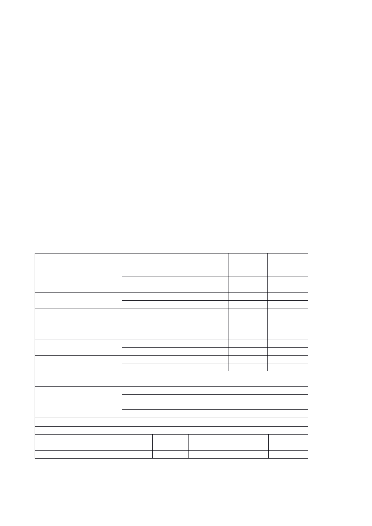
3.Operating
A
Jiomax
Transformer
Relay Switching and
Aux. Supply Circuit
Output Switch Circuit
Reference
Voltage
DC
Voltage
Sampling
Rectify
and Filting
Series
Setting
Amplify
Gate
-
CC
Diff
Ampl+-CVDiff
Ampl
+
AC
220V
Meter Circuit
Current
Sampling
Figure 1
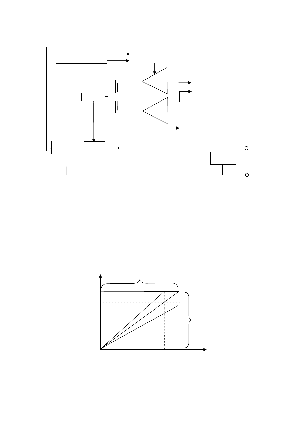
CC
IoIomax
Kvomax
Vo
EDC
CV B
A
R
< R
RL=R
C
RL> R
C
Figure 2
V
omax
0
3.Operating
3.Operating
Principle
Principle
Principle
(((
1)1)1)
Switching
Switching
Switching
Principle
Principle
Principle
Because the changing range of the output voltage is bigger , the secondary of the transformer provides
the output of AC voltage, after it is transferred then app1ied to the rectifier. This procedure is
accomplished by the switching control circuit and driver circuit.
(2)
Mutual
(2)
(2)
Mutual
Mutual
Transfer
Transfer
Transfer
Principle
Principle
Principle
ofofof
CVCVCV
Operation
///
CCCCCC
Operation
Operation
When CV is operating, the voltage comparison amplifier is in prior control state for the regulator.
When the output current of CV operation reaches setting value of CC point, CC comparison amplifier
is in prior control state for the regulator. The operati on mode of the circuit converts CV to CC.
Fig 2 shows the characteristics of the switching procedure.
The load value of the conversion point is R
When K = J, the max output power of the power supply is R
constant.
= R
= KV
L
C
omax
/ I
, where 0 ≤ K/J ≤ 1.
omax
=R
=V
L
C
omax
/ I
. Setting that remains
omax
Page 5
5
When K >J, the circuit is operating in C C state. The point
R1R
2
A2A1VOMV
OS
+-+
-
Figure 3
When K <J, the circuit is operating in CV state. The point
Setting that K and J are constant, assuming they are all equal to 1, i.e R = J= l, R
A
will move to
A
will move to
A'
on B C line.
A'
on DE line.
varies, also the
L
circuit can be converted to the certain B point of CV operation line or certain E point of CC operating
region.
By above mentioned, we can know the crossover, point of CC / CV operating modes, they depend on
the setting of the output parameters to change, suck as changing K and J values, on the other hand,
they can be changed by changing the relation between the lo ad and critical load R
, but the mode
C
conversion is accomplished by the built-in electronic circuit itself at last.
An ideal conversion region should be a point, but in fact, it is impossible, from the point of view of
math, this is because in this point, the change of the output voltage or output current is
discontinuousness , in practical conversion procedure, there is a conversion crossover region, of course ,
the smaller, the crossover region is, the better conversion characteristics of CV / CC are.
(3)
(3)
(3)
Adjusting
Adjusting
Adjusting
Circuit
Circuit
Circuit
The adjusting circuit is a series linearly controller, which is controlled by an error amplifier to adjust
the output parameters linearly.
(4)
(4)
(4)
Comparison
Comparison
Comparison
Amplifier
Amplifier
Amplifier
For adjusting grade, the feeding mode of the comparison amplifier is full-float mode. The advantage of
the circuit is that it has a wide adjustment range, high accuracy, simple circuit, high reliability and not
fears to overload or short.
(5)
(5)
(5)
Reference
Reference
Reference
Source
Source
Source
It consists of a 2DW7 C type reference voltage diode with zero temperature coefficients ; it features
simple, reliable circuit, high accuracy and stability.
(6)
(6)
(6)
Indicating
Indicating
Indicating
Circuit
Circuit
Circuit
It consists of two magnetic-electric meters with high sensitivity, which can be controlled by the key
controllers on the panel. The indicating accuracy is 2.5 grades .
(7)
(7)
(7)
Operating
Operating
Operating
Principle
Principle
Principle
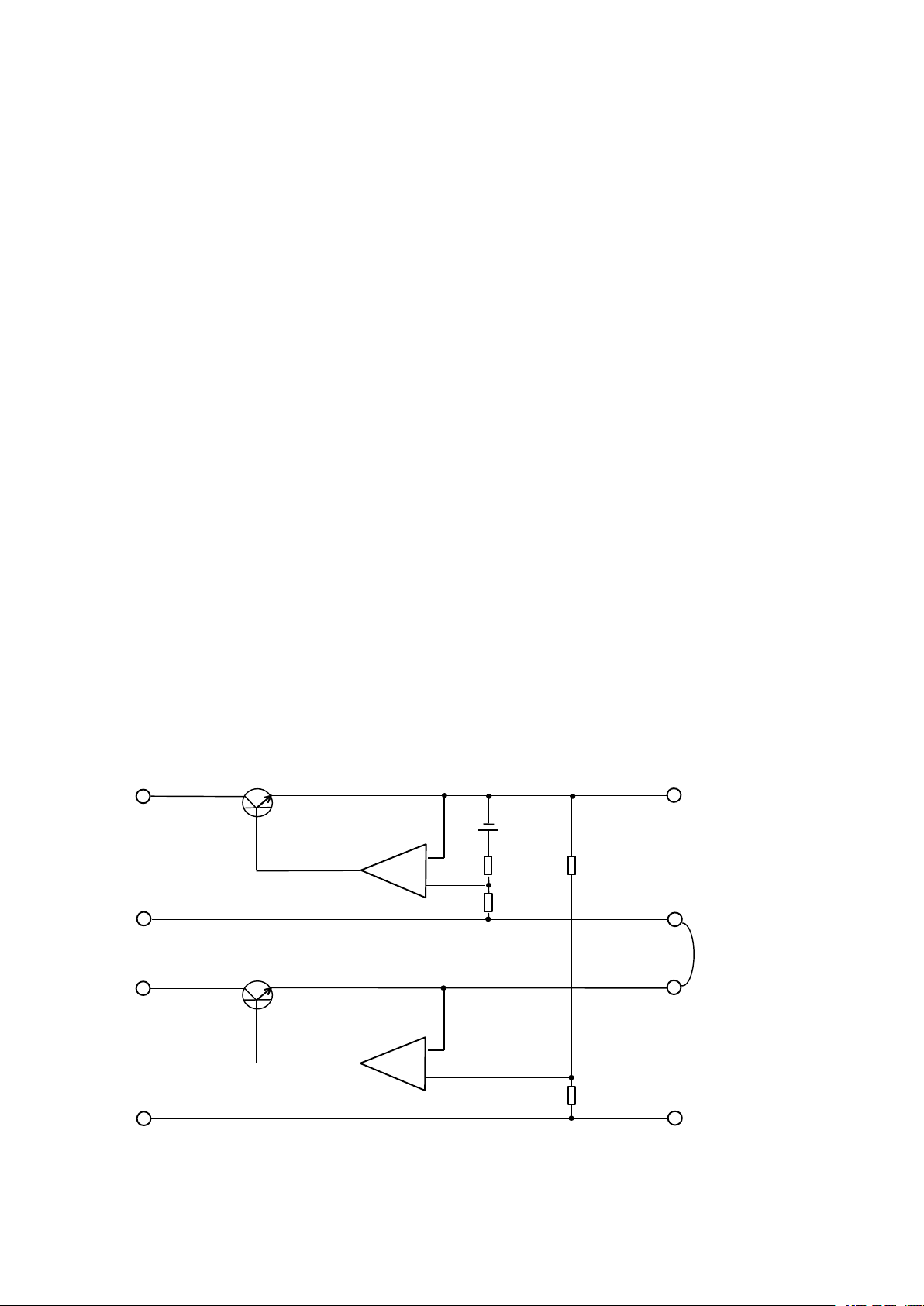
Series
ofofof
Series
Series
Master-Slave
Master-Slave
Master-Slave
Tracking
Tracking
Tracking
The schematic diagram is shown as Figure3.
If R1 = R2, when the output voltage across the two input terminals is V
= 0, it must be V
in
= V
os
, i.e
omo
Page 6
6
the output of the slave varies with the output changes of master.
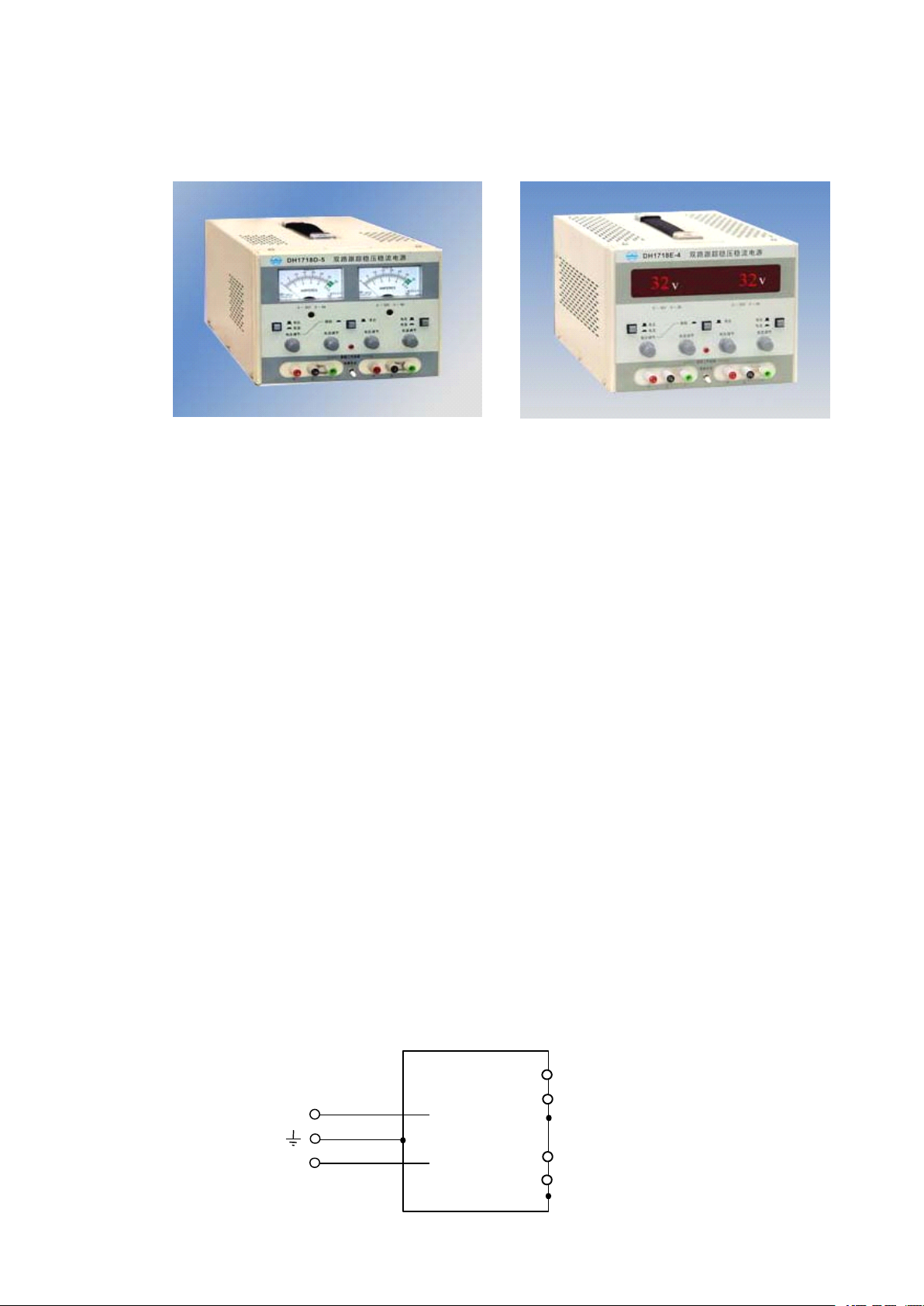
L
N
GND
GND
-+-
+
DH1718
Figure 4
Configuration
4.4.4.
Configuration
Configuration
5.5.5.
Applications
Applications
Applications
(1)
Front
(1)
(1)
Front
Front
Volt
Amps Ammeter Indicating the output current
V oltage V oltage setting Adjusting the output of CV
Current Current setting Adjusting the output value of CC
Tracking Tracking operation Series tracking operation knob
Independent Non-tracking
GND Ground terminal C a se grounded blinding post
C onnect for tracking C onnection in Series short connection tracking operation
line series tracking operation
(2)
Operating
(2)
(2)
Operating
Operating
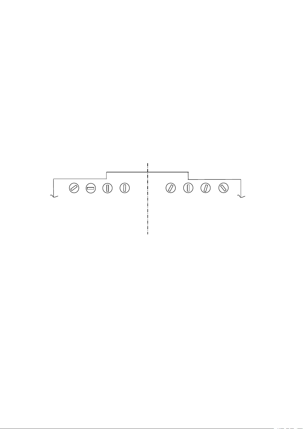
l) The key on the left is a function selector of meter indication of the left way. When pressed, it will
indicate the output current of this way otherwise, indicates the output voltage, the key on the right is
the same as mentioned above.
2) The key in the middle is a tracking / normal selector switch, pressing the key, a short connection
line is added between the negative output terminal of the left way and lh. positi'e and the positive
terminal of the right way. After power on, the instr ument begins operation in master-slave tracking
state.
3) The output voltage is set when the output terminal is open circuit; the output current is set when the
output terminal is circuit-shorted.
(3)
Ground
(3)
(3)
Ground
Ground
1) G round schematic diagram or the power supply is shown in Fig4.
Panel
Panel
Panel
Connection
Connection
Connection
Show
Show
Show
V oltmeter Indicating the output voltage
Instructions
Instructions
Instructions
Method
Method
Method
Page 7
7
Users can connect this power supply to ground or into their own system grounded potential according
W
1
W
2
W3W4W4W
3
W
2
W1master
slave
to their use cases.
2) 1 series operation or series master-slave tracking operation, in principle, one terminal of four output
terminals of the two ways is only allowed to connect with the cabinet .
3) The benefit of ground connection is safe, further it can decrease ripples and harmful spurious wave
and 50Hz interference caused by grounded, potential difference.
Maintenance
6.6.6.
Maintenance
Maintenance
1) Period Check: Should make period inspection after the instrument operation a long-time, the
operating, performances of the unit would have some changes, therefore users should make inspection
for this instrument. Procedure as below:
a. Voltage and current output range
b. Indicating accuracy of the meter
2) General Calibration
a. Adjustable component functions of PCB (see Fig. 5 )
Fig ure 5
W1, Max. Range limit of the output voltage
W2, Max. Range limit of the output current
W3, Accuracy calibration of ammeter
W4, Accuracy calibration of voltmeter
b. Mechanical Zero Calibration of the Meter
When the meter pointer deflected to mechanical zero point, a screw driver can be used to rotate
“ Mechanical Zero ” button below the meter on the panel making it recovery.
c. Ca1ibration of Output Voltage Range
A
digital voltmeter is applied to the corresponding output terminal; the output voltage is set to max.
Then W1 is set to make the readings in the digital meter indicated to 32.5V ≤ V
omax
≤
32.7V,
meanwhile, you can observe indicating value of the voltmeter such as the indication value of the
deflected digital voltmeter and can trim potentiometer W4 in coincidence with the readings as possible .
d. Calibration o f Output Current Range
A
5W standard resistor is connected across the output terminal; the voltage output of the circuit under
test on the panel is set to min, but the current output to max. The digita1 voltmeter is collected across
1 Ω resistor, again power is on, and the output voltage is set to max. Until the readings on the digital
meter remain constant basically. At this time the circuit is operating in CC state, W2 is adjusted, the
voltage on the digital meter is:
Page 8

8
2.2V ≤ I
Model
DH1718-2
DH1718-3
DH1718-4
DH1718-5
Vomax
33V
61V
33V
33V
Iomax
2.25A
1.25A
3.25A
5.25A
Model
DH1718-2
DH1718-3
DH1718-4
DH1718-5
Fuse
2.5A
2.5A4A5A
Meanwhile, should observe whether the current indication value of until is in ordnance with the
readings on the digital meter, otherwise should trim W3.
NOTE:
NOTE:
NOTE:
specifications, the faults will occur.
7.7.7.
Overall DH1718 includes :
l) DH17l8 (master) 1
2) Operating manual 1
3) Input fuse holder BG XP φ 5x 20 1
Connection strap for tracking operation
The output voltage and current can not be set too large, if the readings exceeded the given
Completeness
Completeness
Completeness
omax
'R (=l Ω ) ≤ 2.25V
Storage
8.8.8.
Storage
Storage
Model DH1718 should be stored at the temperature 5-45 ℃ , relative humidity ≤ 80% in vellti1ated
room without smoke, gas, acid, alkali as well as gas and volatile solvent, dust.
Quality
9.9.9.
Quality
Quality
After delivery within l8 months, if users abide
applications, but the quality is poorer than given specifications, our factory is responsible for repairs
and replacement free of charge.
Guarantee
Guarantee
Guarantee
by
the regulations of transportation, storage and
 Loading...