

Page 1

odel
MMM
odel
odel
DH1716
DH1716
DH1716
FFF
amily
amily
amily
CC/CV
DCDCDC
CC/CV
CC/CV
PPP
User
User
User
ower
ower
ower
SSS
Manual
’’’
sss
Manual
Manual
upply
upply
upply
Dahua
Dahua
Dahua
Company
Company
Company
Electronic
ofofof
Electronic
Electronic
Instrument
Instrument
Instrument
ininin
Beijing
Beijing
Beijing
Page 2

2
NOTE:
CONTENTS
CONTENTS
CONTENTS
1 . D escription
2 . Operating Features
3 . Operating Principle
4 . Applications and Operating
5 . Maintenance and Replacement
6 . Completeness of the Instrument
7 . Quality Warranty
Checking
Checking
Checking
No matter the output of the load
checking the specifictions of
terminal on the rear panel (see SJ2811-standard).
CV.
Please connect a checking wire to +S,-S connection
Specification
Specification
Specification
is
from the front or rear output terminal,When
Page 3
3
Description
Model
Spee
DH1716-1
DH1716-2
DH1716-3
Setting Range of
Output
Voltage
0~12.5V
0~18.5V
0~18.5V
Control Range of
Output
Voltage
0~12V
0~18V
0~18V
Setting Range of
Output Current
0~50.5A
0~50.5A
0~30.5
Control Range of
Output Current
0~50A
0~50V
0~30V
Model
Spee
DH1716-4
DH1716-5
DH1716-6
DH1716-7
Setting Range of
Output
Voltage
0~36V
0~62V
0~103V
0~13V
Control Range of
Output
Voltage
0~35V
0~60V
0~100V
0~30V
Setting Range of
Output Current
0~20.2A
0~10.2
0~5.2A
30.5A
Control Range of
Output Current
0~20A
0~10A
0~5A
0~30A
1. Description
Description
Model DH1716 family
is
a single — channel CV/CC power supply which provides a
medium power with CV 、 CC auto — crossover operation mode. In order to improve the
reliability of the power supply, it adopts a phase control circuit, an over — voltage
protection circuit at the output terminal and a built — in over — temperature protection
relay. This power supply off
Remote resistance programming and remote voltage programming .so it
ers
functions of master — slave series and parallel connection .
is
an ideal DC
stabilized power supply .This unit can be widely used in factories research institutes,
laboratories and vario
Technical
2.2.2.
Technical
Technical
us
national economic departments.
Features
Features
Features
2.1.Product Specifications
2.1.
Performances and Specifications
2.2.1. In CV Operation: Source effect: 0.005%+1mV
Load effeft: 0.005%+2mV
P ARD(Period and Random Deviation):1mV(rms)
2.2.2. In CC Operation: Suorce effect : 0.005%+10mA
Load effect: 0.005%+10mA
P ARD (Period and Random Deviation ):20mA (ram)
2.2.3.
Voltage
drift in CV operation:5 × 10
2.2.4 . U sing two sets of similar products in series
2.2.5. U sing two sets of similar products in parallei
-4
+5mV/1hs(20 ± 2 ℃ )
is
allowable
is
allowable
2.2.6. Remote programming in use (with an external sampling function)
2.2.7. Remote resistance programming output voltage:
its
resistance value: 0~10K Ω
2.2.8. Remote voltage programming output voltage: voltage range: 0~10V
Page 4

4
2.2.9. Remote resistance programming output current: resistance range:0~10 k Ω .
~220v
50Hz
CV
Operational
Amp .
CC
Operational
Amp .
R
R ect and
Filter
Series
Regulator
Phase
Control
Tran s
former
Aux. Power
Supply
Current and voltage
Control Circuit
Gate
Circuit
Over-voltage
Protection Circuit
Amp.
Circuit
Fig.1
2.2.10. Remote voltage programming output current: voltage range: 0~10V .
2.2.11.*Over-volatage protection voltage:5.5~40V adjustable, when the instrument
has an over – voltage output, the switch of the unit can cut off total source automatically
(when “ OUTPUT ”
is
on)
2.2.12. * Accuracy of the meter :2.5%,using a digital meter.Indication accuracy: 1%
± 2 counts
2.3. Warm up :15 minutes, but when measuring drift for 1 hour
is
needed
2.4. * Power consumpsion of the whole unit: apparent power: 2.3KW(at 242V)
actual power consumpsion: About 1.2KW(depending on the circuit)
2.5. * Output power :700W
2.6. Environment condition: Conform to Ⅱ group in the
Table
of Sandard
SJ2075-82 (General Programme of Electronic Measuring Instrument Environment Test)
2.7 Continuous operation: 8hs
2.8 Power supply:AC 220V ± 10%
2.9 Frequency of power supply:50 ± 2.5Hz
2.10 * Dimensions:230 × 16 0 × 550mm
2.11 * Weight: About 30kg
Operation
3.3.3.
Operation
Operation
Principle
Principle
Principle
3.1. Circuit Characteristics
The voltage drop of a regulator
is
fed back to phase-control circuit U13-2 for
compareson so that can change the conducting angle of SCR,i.e,itcan change the output
voltage of a rectifier so
as
to keep the voltage drop on the regulator constant basically
The CV/CC circuits transfer signals to a gate circuit simutaneously, according to
Page 5
5
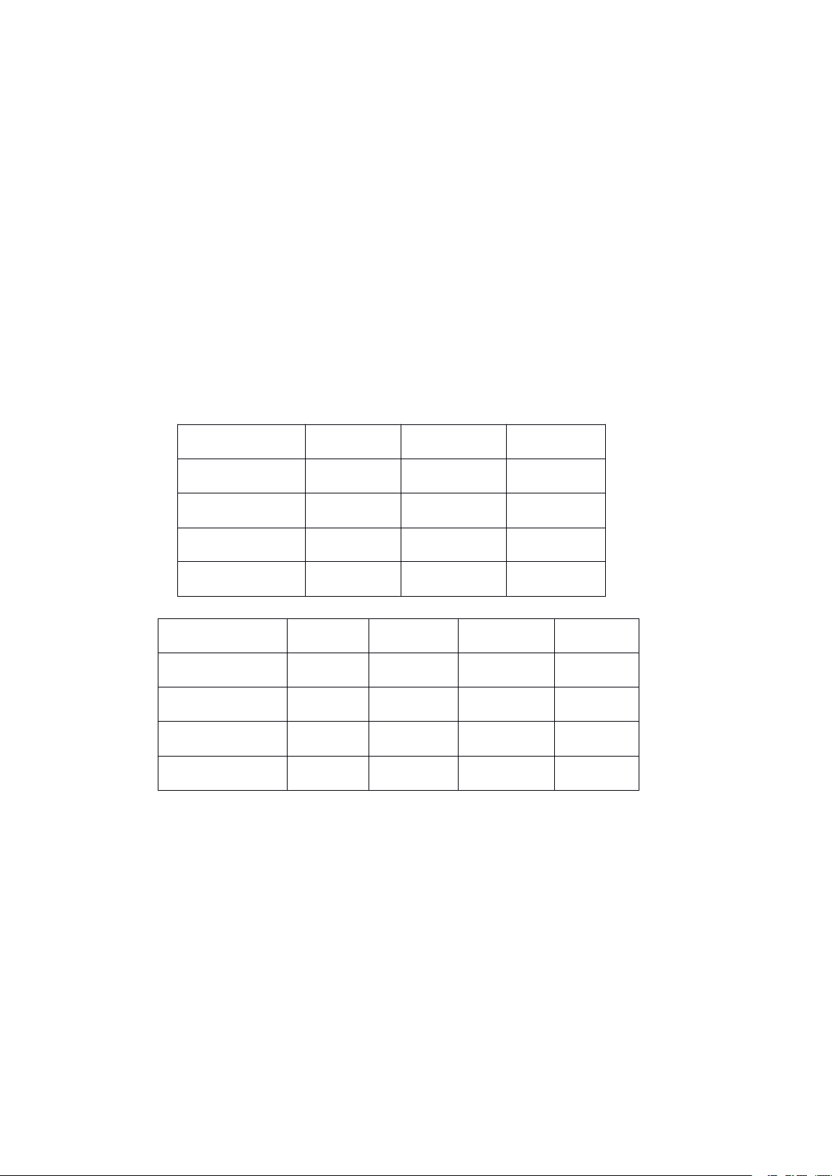
the needs of the load, determinate
10V
10A5A05VD
CBA
RL=2 Ω
RL=0.5 Ω
RL=1 Ω
CCCVFig.2
it is
in CV operation or CC operation. The green lamp
lights in CV operation mode. The red lamp lights in CC operation mode. The voltage
and current can be preset when the instrumemt has no output.
3.2. Brief Description of CV Section
An
adjustable reference circuit consists of
multiturn potentiometer
operational amplifier U4
on
the panel, vernier potentiometers VR1 and VR2. Single
is
a sampling amplifier of CV section. The output voltage
output terminal through a voltage divider along with a reference voltage
operational amplifier U4-3. The positive terminal of the output voltage
an
operational amplifier 1/2 U3,a
is
applied to the
is
connected to
at
the negative terminal of operational amplifier U4-2,the voltage from the output te rminal
of the amplifier passes through the gate circuit and
is
amplifed to control the regulator.
3.3. Brief Description of CC Section
An
adjustable reference voltage circuit consists of an operational amplifier 1/2 U3, a
potentiometer
amplifier U5
of the standard sampling resistor along with the reference voltage
on
the panel, vernier potentiometers VR3 and VR4. Single operational
is
an sampling amplifier of CC section. The voltage
at
the negative term inal
is
appied to the positive
phase terminal of sampling amplifier U4-3,the negative terminal of amplifier U4-2
connected to the positive termnal of the sampling resistor. The output v oltage from the
amplifier passes through the gate ciruit and
is
amplified to control the regulator.
3.4. CV/CC Conversion, CV Mode~CC Mode
Set the current potentiometer, CC
is
set to a preset value to reduce the resistance
the load. The output current increases. when the output current has reached the preset
current value, the oupout voltage decreases, the output current also can not incr ease, that
means the instrument has gone into CC operation mode, even through the resistance
the load
is
shorted to zero, the output current also can not increase ,that means the
instrument can transfer from CV operation mode into CC operation mode aut omatically,
making the load no over-current ,meanwhile also protecting the instrument itself, viceversa, that
is
to
say
,the CV/CC can transfer operation modes of the power supply
automatically.
the
is
on
on
Fig.2 shows the operating points and range of the preset voltage /current of the
load line.
Page 6

6
When the output voltage
151491110
MODEL DH17 1 6 DC POWER SUPPLY
0-35V 20A
A A
V
POWER
CURRENT
+
VOLTAGE
cc
cv
of the load
is
at A
point, then RL= ∝ ,when RL=2 Ω ,the operating point
when RL=1 Ω , the operating point
is
10V the preset current
is
at
C ,If the load decreases from RL=1 Ω to RL=0.5
is
10A.whlie the operating point
is
at B point.
Ω again ,then the operating point will move from C point to D point, the power supply
will convert from CV region into CC region to operate, the operation mode converted
C point
× RL =10A × 0.5 Ω
is
specified
as
crossover point. The voltage
=5V.
on
the load
in
CC operation mod
at
e
Io
Applications
4.4.4.
Applications
Applications
and
Operation
and
and
Operation
Operation
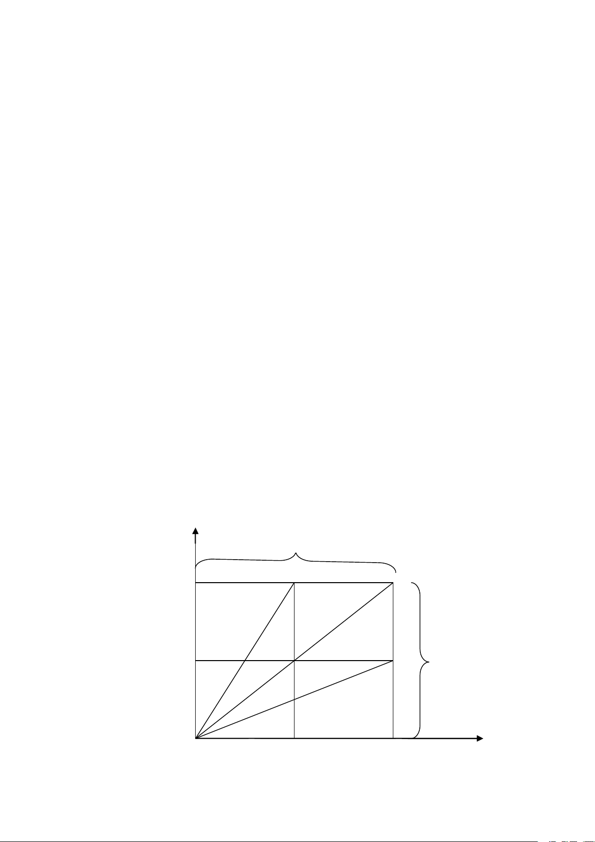
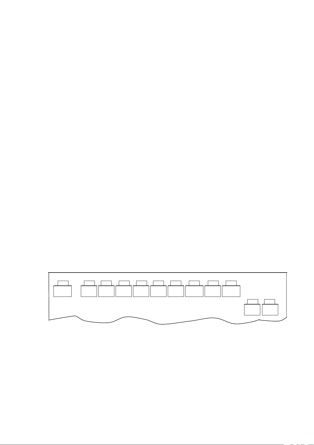
4.1. Introduction of Front Panel and Rear Panel(see next page)
1. Power Supply Switch
2. V/I Checking, V oltage/Current Pre — Display Knob
During pressing, pre — voltage/current are displayed
respectively. When the output switch
is
not turned on. Don ’tpress this knob, also the
voltmeter can display pre — voltage value.
3. OVP CHECK NO-Self – Locked Key
During pressing the knob ,the voltmeter will display over — voltage protection
preset value, when the over — voltage protection preset value
on
the setting vernier potentiometer.
4. Over — voltage Protection
Voltage
Setting Potentiometer Hole
5. OUTPUT Self – Locked Key
16
13
on
the voltmeter and ammter,
is
required to be set ,hold
12
1
7 2 3 4 5 6 8
12
Page 7

7
11
20
10
9
8
7
6
5
4
3
2
1
Only when pressing the key, the output voltage appears
at
the output terminal.
6. Output Indicating Lamp.The indicaing lamp should light when output.
7. CURRENT Setting Knob.It can change the current preset value.
8. VOLTAGE Setting Knob.It can change the voltage preset value.
9. “ + ” Terminal Binding Post for
10.
“ - ” T erminal Binding Post for
Voltage
Voltage
Output.
Output.
11. GND Point
12. Indicating Lamp of the Power Supply
13. CC Indicating Lamp . When
in
CC operation mode.
14 CV Indicating Lamp. When
it
lights, this lamp means that the power supply
it
lights that means the power supply
CV operation mode.
15. V oltmeter (Digital Display Type)
It
indicates the output voltage, preset voltage and over — voltage protection
voltage.
16. Ammeter(Digital Display Type)
It
indicates the current output and preset current.
NOTE: This instrument has two displays of the voltage and the current analog
meter and digital meter, plus “ D ” shows a digital meter
is
used to display, for
example,DH1716-4D shows a display of a digital meter.
17. Function Terminal Connection Strap
18. “ + ” ,a positive output terminal of the power supply
19. “ - ” ,a negative output terminal of the power supply
20. “ +S ” , a positive terminal of
21. “ -S ” , a negative terminal of
an
external sampling terminal.
an
external sampling terminal.
on
the rear panel.
on
the rear panel.
22. *Fuse holder contains a 10A fuse tube.
4.2. Operation and Applications
4.2.1.Checking the instrument
counterclockwise. “ CURRENT ” knob
the instrument
is
inserted into 220V local power network.
is
normal. “ VOLT AGE ” knob
is
rotated fully clockwise. The input terminal of
is
is
rotated fully
is
in
Page 8
8
4.2.2. “ OUTPUT ”
mA
VH
Fig.4
E1+E
2
is
off, when
it is
on, the CV lamp lights, “ VOLT AGE ”
is
set to
the preset value.
4.2.3.If over — voltage protection
the over — voltage protection value can be adjusted. Generally you ’ d better not set so
is
needed, hold
on
pressing “ OVPCHECK ” , so
as
prolong life of the vernier potentiometer.
4.2.4.Hold
current value,
4.2.5.Turn
on
pressing “ V/I CHECK ” , set “ CURRENT ” to the desired preset
in
CV operation, rotate
on
“ OUTPUT ” switch, the output indicating lamp lights, the voltage and
it
fully clockwise.
current output will appear across the output terminal.
4.2.6.If CC operation mode
then voltage preset value can be set to lower. After “ OUTPUT ”
is
required the preset current
is
set to the desired current ,
is
turned on. If CV lamp
lights, can set “ VOLT AGE ” clockwise untill CV lamp goes out, but CC lamp lights .i.e
CV mode has been converted into CC operation mode.
4.2.7.If the master and slave supplies are used
in
series, please make connection
follows:
+
to
as
Master Slave
+
+
-
1
1
3
2
2
4
R
3
4
6
5
5
6
8
7
8
7
-
9
10
10
9
1211
11 12
-
Master
Slave
a. Disconnect the slave supplies (3)and(4),the master (5) connects a resistor to the
slave supply(4).
Its
resistance value is: R -10k Ω VH
:
Rated value of output voltage control
range.
b. The output negative terminal of the master supply
terminal of the slave supply, The chassis of the master supply
is
connected to the positive
is
connected with the
chassis of the slave supply, only the output negative terminal of the slave supply
shor ted
in
conjunction with the chassis.
c. The master supply controls the output voltage, if no 26K Ω resistor, then a 27 K
Ω resistor can substitute, the output voltage of the slave supply
master supply, but the output
is
still E1+E2.
is
lower than that of the
d. Power of resistor ≥ 1/2W
4.2.8.If the master and slave supplies are used
in
parallel, please make connection
follows:
is
as
Page 9

9
Master
Slave
Master
+
Slave
+
I 1 +I 2
-
-
1
2
1
2
3
4
3
4
5
5
a. Disconnect the slave supply (8) and (9),the master supply (11)
the slave supply(11),the master supply (12)
6
7
6
7
Fig. 5
8
9
8
9
10
10
11 12
is
is
connected with the slave supply(10).
b. The output positive terminal, negative terminal, the chassis of the master supply
are
all
connected with that of the slave supply correspondingly. The output negative
terminal of the master supply
c. Before the master supply
preset voltage
is
set to almost same value of the two power supplies, after the two
supplies are connected
ma ster supply
is
in
CV operation mode.
4.2.9.If the remote programming
is
connected with the chassis.
is
not connected
in
parallel, the slave supply
is
needed, should make connection
in
parallel with the slave supply ,the
is
in
CC operation mode, while the
R
L
1211
connected with
as
follows:
+S
+
R L
-S
-
Fig.6
a. Disconnect (+S) and (+),(-S) and (-) uses a shielded two-wire cable to be
connected according to the following diagram, the coating layer of the shielded cable
connected to the positive terminal.
b. When the lead
is
longer, should connect a 100 μ F capacitor to the load
parallel, the voltage endurance should be more than the output voltage and should notice
its
polarity.
is
in
Page 10
10
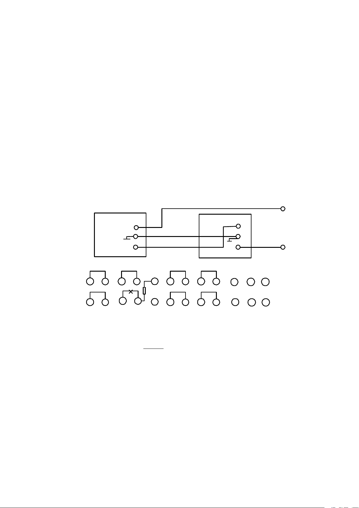
4.2.10 If the remote resistance programming output voltage
V1
Fig.8
make connection
as
follows:
is
needed, should
1
3
2
4
6
5 8
7
Fig. 7
a. Disconnect (1) and (2), the shielded two — wire cable
Fig.7.
b. R
otherwise, the output voltage will result
c. The output voltage
is
a 10K Ω potentiometer which can not be open circuit
in
over — voltage.
is
proportional to the resistance value.
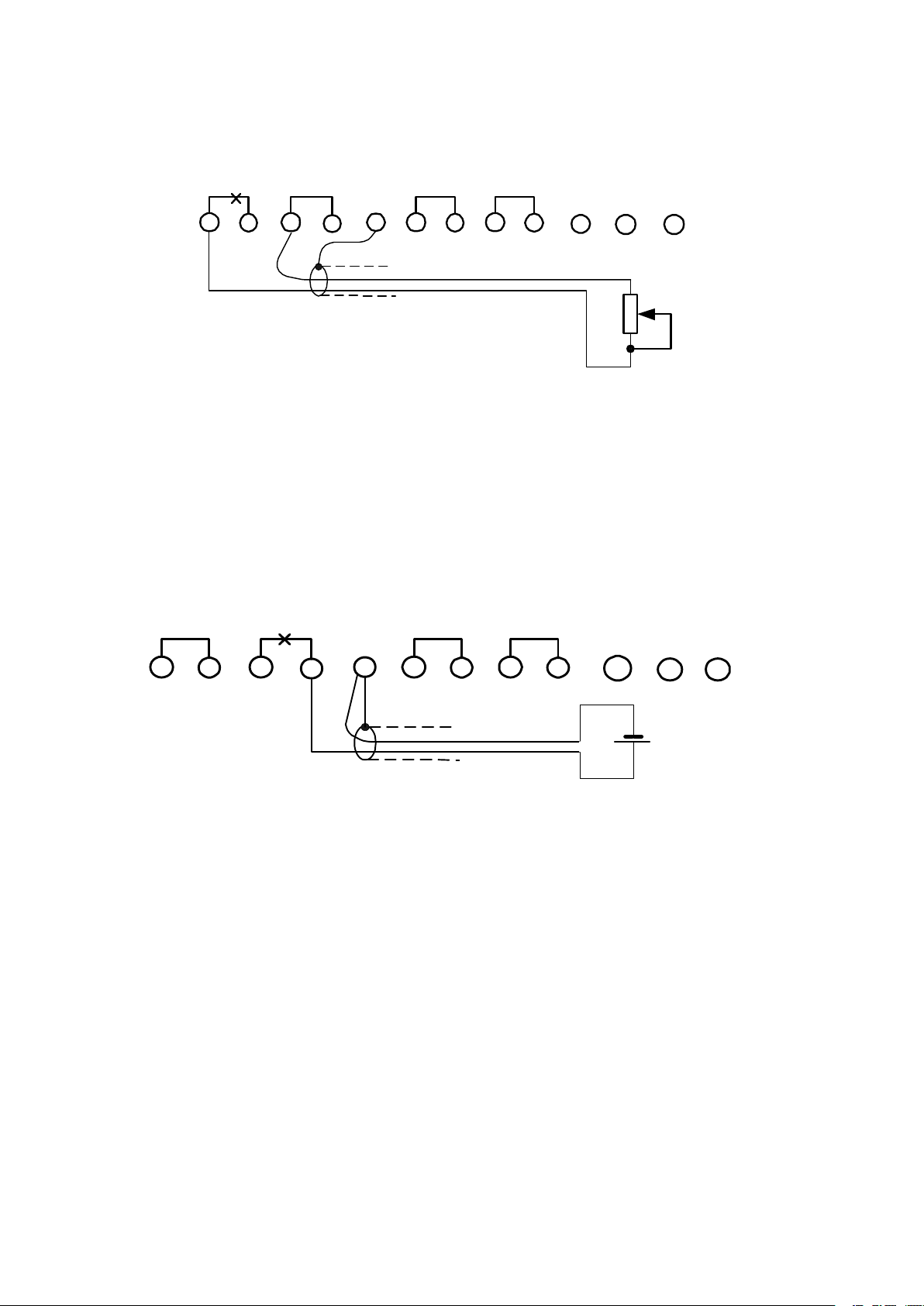
2.4.11 If the remote voltage programming output voltage
connection
1
as
follows:
2
3
4
5 8
6
7
9
10
is
is
9
10
1211
R
connected
as
shown
at any
required, should make
1211
in
time,
+
a. Disconnect (3) and (4), the shielded two — wire cable
Fig.8. “ + ” terminal
is
connected with (4) , “ - ” terminal with (5) , the outer coating of the
cable with (5).
b. The output voltage
is
proportional to the controlled voltage,
need a 10.5V to reach a 35V output only, but the externally – controlled voltage
allowed too high, the external voltage
is
floated.
4.2.12 If the remote resistance programming output current
make connection
as
follows
is
connected
it is
is
required, should
as
shown
possible to
in
is
not
Page 11

11
1
V2
3
2
4
6
5
8
7
9
11
10 12
R
Fig.9
a. Disconnect (6) and (7), the shielded two — wire cable
b. R
current
is
a 10K Ω potentiometer which can not be open
is
out of control,
as
soon
as
the load current becomes larger, can cause the damage
is
at any
connected
as
shown
time otherwise, the output
in
to the regulator.
c. The output preset current
4.2.13 If the remote voltage programming output current
connection
as
follows:
3
is
proportentional to the resistance value.
4
6 71 2 5
8
9
is
required, should make
10 11
12
+
-
Fig. 10
a. Disconnect (8) and (9), the shielded two — wire cable
Fig. 10, the positive terminal of the externally – controlled voltage
is
connected
is
connected with (9),
as
shown
the negative with (11), also the outer coating of the cable with (11).
b. The output current
is
proportional to the controlled voltage,
it is
possibleto
need a 10.5V to reach a 20A output current only, but the externally — controlled voltage
can not be too high.
c. The external voltage
4.2.14 Some Attentions
a.
In
CV mode operation, the determination of the load effect should locate
is
floated.
in
Applications
conjuntion point (i.e.in conjuction with +S,-S) with the sensing terminal.
b. The output terminal
on
the front and rear panels can be used, when checking
specifications, should make inspection according to the specifications step (a).
c. The power supply
4.2.15 Attentions
is
not suitable to use Model 614 AC voltage regulator.
in
Applications
a. Keep air flowing, when installing other instruments, should place them far
Fig.9
in
in
Page 12
12
30cm from ventilator.
VR20
VR2
VR1
VR9
VR3
VR4
VR6
VR7
VR8
VR5
VR11
VR10
b. Prevent the instrument from placing
c. The induced instrument can not be placed nearby the power supply.
in
dirty or poisonous cnvironment .
Maintenance
5.5.5.
Maintenance
Maintenance
and
Replacement
and
and
Replacement
Replacement
5.1. Maintenance
5.1.1.Opening the cabinet, remove two screws
screws
on
each leftside, four screws
on
the top cover.
on
the front and rear panel and three
5.1.2.*Replacement of Fuse
The fuse can not be used when
it is
more or less than the specified range,itshould
be φ 6x30 — 10A.
5.2. Adjustment
5.2.1. Setting Range of Output V oltage
The CV control
OUTPUT switch, anexternal voltmeter
is
rotated fully counterclockwise step
is
used for monitoring, VR2
by
step, press down
is
set to make the
output to zero (allowable to set to 0.2V) The CV controlisrotated fully clockwise step
step,
at
this time. note that the voltmeter indication
by
adjusting VR1, making CV control rotated fully clockwise and the output to 36~37V.
is
monitored externally, while rotating
5.2.2.Adjustment of the V oltmeter Indication (before power applied, first of all,
adjust zero point of machinism).
Turn off OUTPUT switch , the CV knob
is
set to 0V off the meter indication.
Turn of OUTPUT switch, VR11
set to 35V ,VR7
with the readings
is
set to make the output voltage
on
monitoring voltmeter.
Turn off OUTPUT switch, VR5
is
set to zero of the meter indication, the output
is
is
rotated fully counterclockwise, VR8
on
the voltmeterindicator
in
accordance
set to make the output voltage indication
accordance with the preset indication value.
by
is
in
Fjg. 11
5.2.3.Setting of Output Current Range
The CC control
variable resistor
resistor will be shorted step
c ontrol
is
rotated fully clockwise step
is
rotated fully counterclockwise, the voltage
is
connected to the ammter, turn
by
step.VR4
by
is
preset to 3~5V ,the
on
OUTPUT switch, the variable
is
set to make output current to zero, the CC
step to make indication of the external
monitoring ammter to 20A (or a little larger ). The variable resistormust not be shorted,
can use a lower resistance value.
5.2.4.Setting of Ammeter Indication (before power
is
applied, first, adjust
Page 13

13
machinism point)
1
1
1
2
The CC control
is
off, VR10
RL
is
set to make the output to 20A, mean while VR9
Press down V/I CHECK, the indication of the ammter
),when they are unconformable, set VR6,the preset value
value
in
5.2.5.Repairment
Normal troubles should be troubleshooted according to the following methods:
1. Power not applied. the indicating lamp does not light.
Maybe something wrong with power line, poor contact, input fuse
2. The power on, but
Maybe over — voltage protection voltage
regulator
3. Output voltage
Maybe built —
misconnected, The output diode
HF oscillation thus can shunt a capacitor to eliminate.
4. Output
Maybe the terminals (1) and (2) , (6) and (7) have dropped off, CV and CC
potentiometers are open.
5. Output voltage and current are not controlled
The terminal
defictive.
14. The output
Connection wires dropped off or misconnected, the voltage of the power supply has
exceeded the specifified range, a special load causes oscillation, the sensing terminal
contactisnot tight, should avoid strong electric — magnetic field nearby.
is
CV operation mode.
is
broken.
is
is
rotated fully counterclockwise, turn
set to make indication of the ammter to zero,
is
as
soon
as
OUTPUT switches on, the power
is
lower than the voltage output, individual
is
zero or lower.
in
output wires are loose and off. The function terminal
is
damaged, due to longer output lead line, resulting
too large.
by
the knobs.
on
the rear panel
is
not stable.
is
misconnected. May be control circuits are
on
OUTPUT switch, the load
in
connection with the load,
is
set to make indication to 2 0A.
also 20A (in CC operation mode
is
always more than output
is
broken..
is
off.
is
in
Completeness
6.6.6.
Completeness
Completeness
1. Main Power Supply
2. Power Lead line
3. Operating Manual
4. Fuse Tube BGXP — φ 6x30 — 10A
5. Output Protection Board, T erminal and Protection Board
Quality
7.7.7.
Quality
Quality
After delivery within 18 months, if users abide
storage and applications. but the quality of the product does not meet the specifications
given, our factory
1. *P ARD 1mV(rms)
2. 5.5~40V range of over — voltage protection voltage
Warranty
Warranty
Warranty
is
the
ofofof
responsible for repaiment and replacement free of charge.
Instrument
the
the
Instrument
Instrument
1 for each
by
regulations of transportation,
is
for Model DH1716-1~5, 2mV (rms) for Model DH1716-6
is
adjustable for Model.
Page 14

14
DH1716-4 .The range of other models are
as
follows:
Model DH1716-1~3: 5~20V
Model DH1716-5: 8~65V
Model DH1716-6: 15~110V
3.
Power consumption: 1.2KW for Model DH1716-4, Model DH 1716-2
than 1.2KW , other models are
all
less than this value.
4. Output power:700W for DH 1716-4, other models are
to rated output voltage and current value.
5. Dimensions: 230 × 160 × 550mm only for DH1716-3 and DH1716-4,larger or
smaller for other models.
6. Weight: About: 30kg for DH1716-3 and DH1716-4 only ; other models are
larger with increasing current.
7. Fuse tubes: except φ 6x30 – 15A for DH1716-2,others use φ 6x30 — 10A.
(For Model DH1716-6, a
5A
fuse tube
is
added).
8. Because the digital meters are produced
“ - ”
is
shown
symbol may be considered
in
different ways, while “ ”
as
incomplete. For example, “ -0.1 ” , i.e,
“ 0.1 ” . Here for Model DH1716-6,the accuracy of
9.
Model DH1716-7
is
an
expanded type.
is
expressed
all
computed according
by
different manufacturers, the symbol
as
“ - ”
in
partial meters, this
it is
expressed
its
digital meter
is
1% ± 3 digits.
is
more
as
 Loading...