

Page 1

Video Doorbell
User’s Manual
V 1.0.1
Page 2

II
Cybersecurity Recommendations
Mandatory actions to be taken towards cybersecurity
1. Change Passwords and Use Strong Passwords:
The number one reason systems get “hacked” is due to having weak or default passwords. It is
recommended to change default passwords immediately and choose a strong password
whenever possible. A strong password should be made up of at least 8 characters and a
combination of special characters, numbers, and upper and lower case letters.
2. Update Firmware
As is standard procedure in the tech-industry, we recommend keeping NVR, DVR, and IP
camera firmware up-to-date to ensure the system is current with the latest security patches and
fixes.
“Nice to have” recommendations to improve your network security
1. Change Passwords Regularly
Regularly change the credentials to your devices to help ensure that only authorized users are
able to access the system.
2. Change Default HTTP and TCP Ports:
● Change default HTTP and TCP ports for systems. These are the two ports used to
communicate and to view video feeds remotely.
● These ports can be changed to any set of numbers between 1025-65535. Avoiding the
default ports reduces the risk of outsiders being able to guess which ports you are using.
3. Enable HTTPS/SSL:
Set up an SSL Certificate to enable HTTPS. This will encrypt all communication between your
devices and recorder.
4. Enable IP Filter:
Enabling your IP filter will prevent everyone, except those with specified IP addresses, from
accessing the system.
5. Change ONVIF Password:
On older IP Camera firmware, the ONVIF password does not change when you change the
system’s credentials. You will need to either update the camera’s firmware to the latest revision
or manually change the ONVIF password.
6. Forward Only Ports You Need:
Page 3

III
● Only forward the HTTP and TCP ports that you need to use. Do not forward a huge range of
numbers to the device. Do not DMZ the device's IP address.
● You do not need to forward any ports for individual cameras if they are all connected to a
recorder on site; just the NVR is needed.
7. Disable Auto-Login on SmartPSS:
Those using SmartPSS to view their system and on a computer that is used by multiple people
should disable auto-login. This adds a layer of security to prevent users without the appropriate
credentials from accessing the system.
8. Use a Different Username and Password for SmartPSS:
In the event that your social media, bank, email, etc. account is compromised, you would not
want someone collecting those passwords and trying them out on your video surveillance
system. Using a different username and password for your security system will make it more
difficult for someone to guess their way into your system.
9. Limit Features of Guest Accounts:
If your system is set up for multiple users, ensure that each user only has rights to features and
functions they need to use to perform their job.
10. UPnP:
● UPnP will automatically try to forward ports in your router or modem. Normally this would be a
good thing. However, if your system automatically forwards the ports and you leave the
credentials defaulted, you may end up with unwanted visitors.
● If you manually forwarded the HTTP and TCP ports in your router/modem, this feature should
be turned off regardless. Disabling UPnP is recommended when the function is not used in real
applications.
11. SNMP:
Disable SNMP if you are not using it. If you are using SNMP, you should do so only temporarily,
for tracing and testing purposes only.
12. Multicast:
Multicast is used to share video streams between two recorders. Currently there are no known
issues involving Multicast, but if you are not using this feature, deactivation can enhance your
network security.
13. Check the Log:
If you suspect that someone has gained unauthorized access to your system, you can check
the system log. The system log will show you which IP addresses were used to login to your
system and what was accessed.
14. Physically Lock Down the Device:
Page 4

IV
Ideally, you want to prevent any unauthorized physical access to your system. The best way to
achieve this is to install the recorder in a lockbox, locking server rack, or in a room that is
behind a lock and key.
15. Connect IP Cameras to the PoE Ports on the Back of an NVR:
Cameras connected to the PoE ports on the back of an NVR are isolated from the outside world
and cannot be accessed directly.
16. Isolate NVR and IP Camera Network
The network your NVR and IP camera resides on should not be the same network as your
public computer network. This will prevent any visitors or unwanted guests from getting access
to the same network the security system needs in order to function properly.
Page 5

V
Regulatory Information
FCC Information
CAUTION
Changes or modifications not expressly approved by the party responsible for compliance
could void the user's authority to operate the equipment.
FCC conditions:
This device complies with part 15 of the FCC Rules. Operation is subject to the following two
conditions:
This device may not cause harmful interference.
This device must accept any interference received, including interference that may cause
undesired operation.
FCC compliance:
This equipment has been tested and found to comply with the limits for a digital device,
pursuant to part 15 of the FCC Rules. This equipment generate, uses and can radiate radio
frequency energy and, if not installed and used in accordance with the guide, may cause
harmful interference to radio communication.
For class A device, these limits are designed to provide reasonable protection against
harmful interference in a commercial environment. Operation of this equipment in a
residential area is likely to cause harmful interference in which case the user will be
required to correct the interference at his own expense.
For class B device, these limits are designed to provide reasonable protection against
harmful interference in a residential installation. However, there is no guarantee that
interference will not occur in a particular installation. If this equipment does cause harmful
interference to radio or television reception, which can be determined by turning the
equipment off and on, the user is encouraged to try to correct the interference by one or
more of the following measures:
Reorient or relocate the receiving antenna.
Increase the separation between the equipment and receiver.
Connect the equipment into an outlet on a circuit different from that to which the
receiver is connected.
Consult the dealer or an experienced radio/TV technician for help.
Page 6
VI
Foreword
General
This document elaborates introduction, installation, device adding and FAQ of video doorbell.
Model
DB11
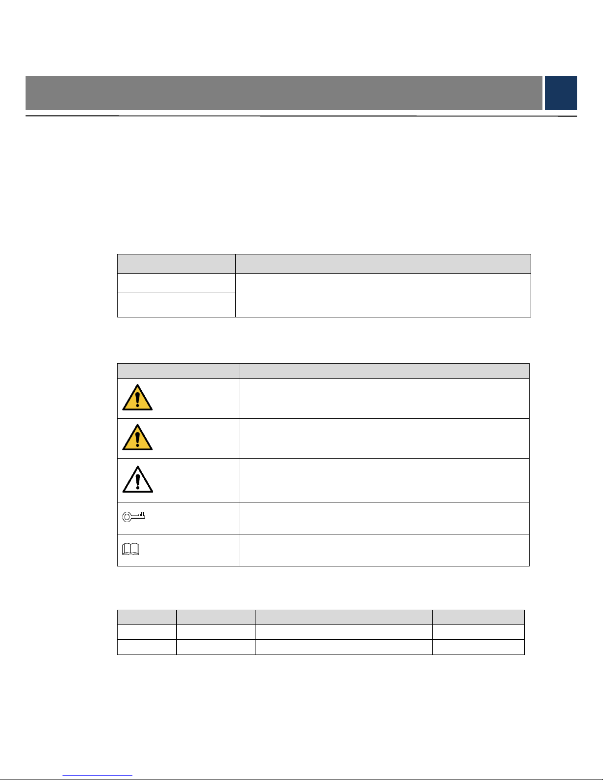
Operation Definition
Italic Content
Note
Device Name
It represents modifiable parameter name. Specific contents are
different depending on settings. Default device name is its serial
number and default channel name is Channel 1.
Channel Name
Safety Instructions
The following categorized signal words with defined meaning might appear in the Manual.
Signal Words
Meaning
DANGER
Indicates a high potential hazard which, if not avoided, will result
in death or serious injury.
WARNING
Indicates a medium or low potential hazard which, if not avoided,
could result in slight or moderate injury.
CAUTION
Indicates a potential risk which, if not avoided, could result in
property damage, data loss, lower performance, or unpredictable
result.
TIPS
Provides methods to help you solve a problem or save you time.
NOTE
Provides additional information as the emphasis and supplement
to the text.
Revision Record
No.
Version No.
Revision Content
Release Date
1
V 1.0.0
First release
2018.3.30
2
V 1.0.1
Add FCC and privacy protection notice
2018.6.21
Privacy Protection Notice
As the device user or data controller, you might collect personal data of others, such as face,
fingerprints, car plate number, Email address, phone number, GPS and so on. You need to be
Page 7

VII
in compliance with the local privacy protection laws and regulations to protect the legitimate
rights and interests of other people by implementing measures, including but not limited to:
providing clear and visible identification to inform data subject the existence of surveillance
area and providing related contact.
About the Manual
The Manual is for reference only. If there is inconsistency between the Manual and the
actual product, the actual product shall prevail.
We are not liable for any loss caused by the operations that do not comply with the Manual.
The Manual would be updated according to the latest laws and regulations of related
regions. For detailed information, see the paper User's Manual, CD-ROM, QR code or our
official website. If there is inconsistency between paper User's Manual and the electronic
version, the electronic version shall prevail.
All the designs and software are subject to change without prior written notice. The product
updates might cause some differences between the actual product and the Manual. Please
contact the customer service for the latest program and supplementary documentation.
There still might be deviation in technical data, functions and operations description, or
errors in print. If there is any doubt or dispute, please refer to our final explanation.
Upgrade the reader software or try other mainstream reader software if the Guide (in PDF
format) cannot be opened.
All trademarks, registered trademarks and the company names in the Manual are the
properties of their respective owners.
Please visit our website, contact the supplier or customer service if there is any problem
occurred when using the device.
If there is any uncertainty or controversy, please refer to our final explanation.
Page 8

VIII
Important Safeguards and Warnings
The following description is the correct application method of the device. Please read the
manual carefully before use, in order to prevent danger and property loss. Strictly conform to
the manual during application and keep it properly after reading.
Operating Requirement
Please don’t place and install the device in an area exposed to direct sunlight or near heat
generating device.
Please don’t install the device in a humid, dusty or fuliginous area.
Please keep its horizontal installation, or install it at stable places, and prevent it from
falling.
Please don’t drip or splash liquids onto the device; don’t put on the device anything filled
with liquids, in order to prevent liquids from flowing into the device.
Please install the device at well-ventilated places; don’t block its ventilation opening.
Use the device only within rated input and output range.
Please don’t dismantle the device arbitrarily.
Please transport, use and store the device within allowed humidity and temperature range.
Power Requirement
The product shall use electric cables (power cables) recommended by this area, which
shall be used within its rated specification.
Please use standard power adapter supplied with this device; otherwise, resulting personal
injury or device damage shall be borne by the user.
Please use power supply that meets SELV (safety extra low voltage) requirements, and
supply power with rated voltage that conforms to Limited Power Source in IEC60950-1. For
specific power supply requirements, please refer to device labels.
Products with category I structure shall be connected to grid power output socket, which is
equipped with protective grounding.
Appliance coupler is a disconnecting device; please keep its convenient operation during
use.
Page 9

IX
Table of Contents
Cybersecurity Recommendations .......................................................................................................... II
Regulatory Information ............................................................................................................................ V
Foreword .................................................................................................................................................. VI
Important Safeguards and Warnings .................................................................................................. VIII
1 Packing List ......................................................................................................................................... 1
2 Device Introduction ............................................................................................................................ 2
2.1 Front Panel .................................................................................................................................... 2
2.1.1 Status Description of Indicator Light ................................................................................... 2
2.1.2 Description of Call Button ................................................................................................... 3
2.2 Rear Panel .................................................................................................................................... 3
2.2.1 Description of Reset Button ................................................................................................ 3
2.2.2 Description of Power Input Port .......................................................................................... 3
2.3 Bottom ........................................................................................................................................... 5
3 Get Started........................................................................................................................................... 6
3.1 Download Lechange Client ........................................................................................................... 6
3.2 Add Device .................................................................................................................................... 6
3.3 Doorbell Call ................................................................................................................................ 13
3.3.1 Online Status of APP ........................................................................................................ 13
3.3.2 Closed Status of APP ....................................................................................................... 14
3.4 Monitoring ................................................................................................................................... 14
3.4.1 Live Share ......................................................................................................................... 16
3.4.2 Full-screen Preview .......................................................................................................... 17
3.4.3 View Alarm Records ......................................................................................................... 17
4 Device Installation ............................................................................................................................ 19
5 APP Operation................................................................................................................................... 20
5.1 Device Management ................................................................................................................... 20
5.1.1 Modify Device Info ............................................................................................................ 20
5.1.2 Modify Device Password .................................................................................................. 20
5.1.3 Link Chime ........................................................................................................................ 21
5.1.4 Ring Setup ........................................................................................................................ 23
5.1.5 Set PIR Motion Detection Zone ........................................................................................ 24
5.1.6 Enable Alarm Info ............................................................................................................. 25
5.1.7 Set Storage Status ............................................................................................................ 25
5.1.8 Set Time Zone .................................................................................................................. 26
5.1.9 Set Image Flip ................................................................................................................... 27
5.1.10 Set Device Share ............................................................................................................ 27
5.1.11 Cloud Update .................................................................................................................. 27
5.1.12 Modify Wi-Fi Config ........................................................................................................ 28
5.1.13 Delete Device ................................................................................................................. 29
5.2 Settings ....................................................................................................................................... 30
5.2.1 Prompt .............................................................................................................................. 30
Page 10

X
5.3 View Message ............................................................................................................................. 30
5.3.1 APP is Online .................................................................................................................... 30
5.3.2 APP is Closed ................................................................................................................... 33
5.4 View Local Files .......................................................................................................................... 33
6 FAQ ..................................................................................................................................................... 35
Technical Parameters ........................................................................................................ 36
Page 11

1
1 Packing List
Check whether device appearance shows obvious damages.
Check whether all accessories are supplied. Packing list is as follows:
Video doorbell
User’s manual
Installation accessories package
Page 12
2
2 Device Introduction
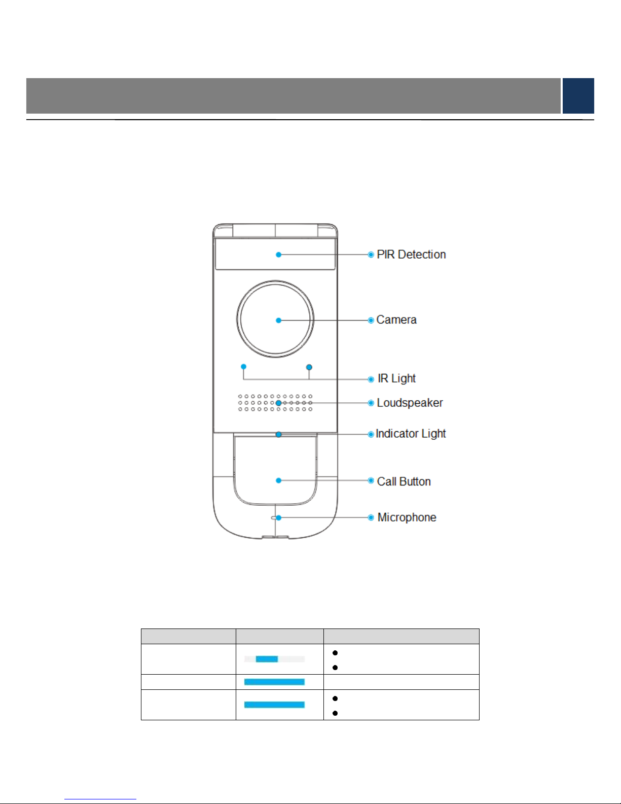
2.1 Front Panel
Front panel includes PIR detection, IR light, camera, microphone, indicator light, call button and
loudspeaker, as shown in Figure 2-1.
Figure 2-1
2.1.1 Status Description of Indicator Light
Status description of indicator light is shown in Table 2-1.
Status
Symbol
Description
Blue Spinning
Calling
Enter AP reset mode
Blue Solid
Talking
Blue Flashing
Not connected with network
Abnormal network
Table 2-1
Page 13
3
2.1.2 Description of Call Button
Short press: Ring the doorbell.
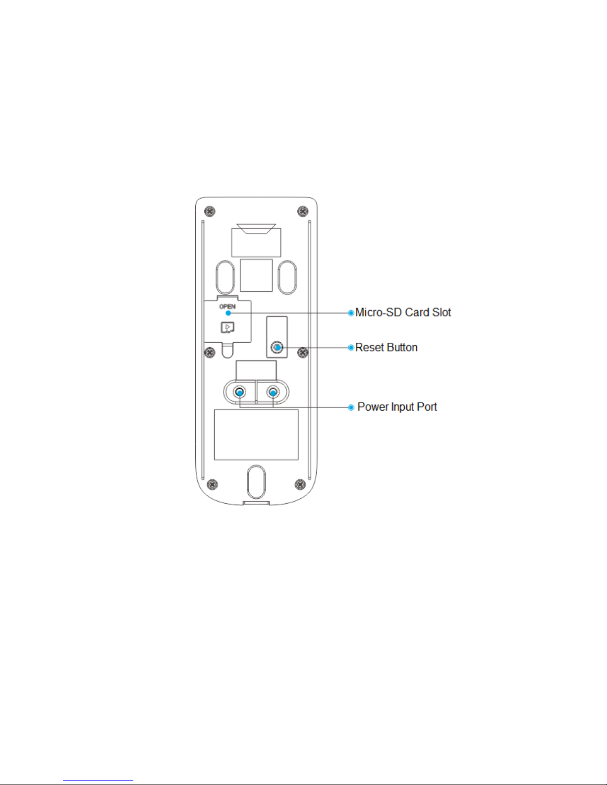
2.2 Rear Panel
Rear panel includes micro-SD card slot, Reset Button and power input port, as shown in Figure
2-2.
Figure 2-2
2.2.1 Description of Reset Button
Press it shortly, and indicator light turns to blue spinning light, representing that the hotspot
has been enabled.
Press it for 10s, and indicator light turns blue and is normally on for 3s. The device restores
factory defaults.
2.2.2 Description of Power Input Port
The doorbell can be matched with AC 16V–24V or DC 12V–24V power adapter. It is able to
connect different chimes under the condition of different power adapters.
With AC 16V–24V power adapter, it is able to connect wired chime (mechanical chime or
Page 14
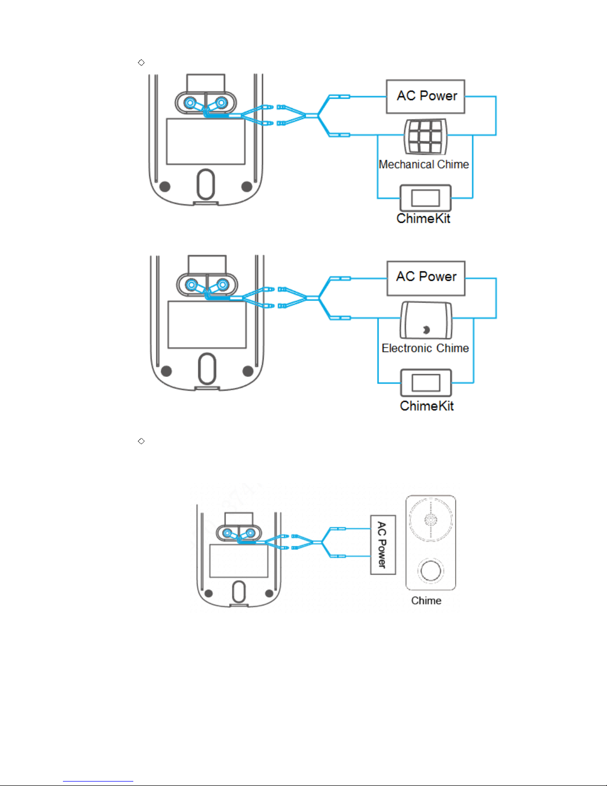
4
electronic chime) or Lechange wireless chime.
Wiring diagram of wired chime is shown in Figure 2-3 and Figure 2-4.
Figure 2-3
Figure 2-4
Wiring diagram of wireless chime is shown in Figure 2-5. It is unnecessary to match
ChimeKit. DS series wireless chime is solely connected with municipal electricity
(strong electricity) network.
Figure 2-5
With DC 12V/24V power adapter, it is able to connect Lechange wireless chime, as shown
in Figure 2-6. It is unnecessary to match ChimeKit. DS series wireless chime is solely
connected with municipal electricity (strong electricity) network.
Page 15

5
Figure 2-6
2.3 Bottom
A screw hole at the bottom is used to fix the device onto the bracket, as shown in Figure 2-7.
Figure 2-7
Page 16

6
3 Get Started
Before installation, add the device in APP; ensure that calling and monitoring functions of
doorbell and APP work normally. Specific operations are as follows:
3.1 Download Lechange Client
Please ensure that your mobile phone has connected with Wi-Fi. Scan QR code below, or
search “Lechange” in APP market, download and log onto APP client. For specific operation,
please refer to relevant Lechange user’s manual.
Figure 3-1
This document takes iOS system as an example and explains operations.
3.2 Add Device
For the first use or reuse after long-term power-off, it takes 2 minutes to start the device.
At device list interface, press + to enter “QR Code Scanning” interface.
Scan QR code on the device or package; or press [Input serial number manually], input
serial number of the device manually, and press [Next].
The system displays a prompt interface to enable device hotspot, as shown in Figure
3-2.
Scan QR code to obtain serial number, and it will display serial number confirmation
interface. Press [Next] to enter the interface as shown in Figure 3-2.
Page 17

7
Figure 3-2
Press Reset Button on the rear panel of the device.
In case of blue spinning light, it means that device hotspot is on.
On APP interface, press [Next].
The system displays a prompt interface to connect device hotspot, as shown in Figure
3-3.
Figure 3-3
Page 18

8
Connect mobile phone Wi-Fi with device hotspot. Hotspot Wi-Fi name is Doorbell-
device serial number.
0
Figure 3-4
On APP interface, press [Next].
The system displays device password setting interface, as shown in Figure 3-5.
If this device is not used for the first time, the interface is to enter device password,
rather than setting the password, as shown in Figure 3-6.
Page 19

9
Figure 3-5
Figure 3-6
Set device password and email, and press [OK].
The system displays available Wi-Fi list, as shown in Figure 3-7.
Page 20

10
Figure 3-7
Choose the Wi-Fi network to be connected.
The system displays Wi-Fi connection interface, as shown in Figure 3-8.
Figure 3-8
Input Wi-Fi network password and press [Connect].
The system displays indicator light judgment interface, as shown in Figure 3-9.
Page 21

11
Figure 3-9
Please check if device indicator light is blue ON.
If the blue indicator light doesn’t turn on, press [Add again], repeat above steps to
add it again.
If blue light turns on, it means that the connection is successful.
Press [Yes] to add the device to APP.
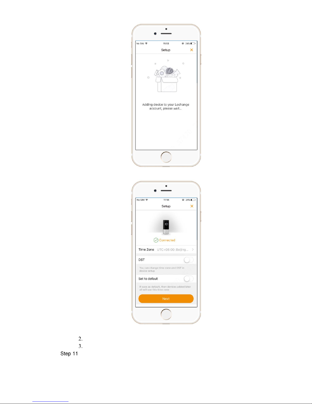
Start to add the device to APP, as shown in Figure 3-10. After adding it
successfully, display a time zone setup interface, as shown in Figure 3-11.
Page 22
12
Figure 3-10
Figure 3-11
Set “Time Zone” and “DST”.
Press [Next] to enter real-time monitoring interface.
Set the local time zone and press [Next] to complete adding.
Page 23

13
3.3 Doorbell Call
3.3.1 Online Status of APP
Press [Call Button] on the doorbell.
In case of blue spinning light, APP displays call interface, as shown in Figure 3-12.
Hang up automatically if no one answers within 1 minute.
Figure 3-12
On APP interface, press [Answer] to answer the call.
Blue indicator light is normally on. For operation of keys on APP interface, please refer
to Table 3-1.
Figure 3-13
Key
Note
Mute
It is playing ringtones. Press this key to turn off ringtones, and this key turns to
. Press it again to play ringtones.
Accept
It is waiting for you to accept the call. Press this key to accept the call.
Hang up
It is waiting for you to accept the call. Press this key to reject the call.
It is receiving videos at present. Press this key to turn off video, and this key
turns to . Press again to turn on video.
It is in voice talking status. Press this key to turn off voice talking, and this key
turns to . Press again to enable voice talking.
Page 24

14
Key
Note
Present video is standard definition status. Press this key to switch to high
definition status, and this key turns to . Press again to switch to
standard definition status.
Press this key to get a screenshot of the video, and save the picture in APP
local file.
Press this key to start recording. Recording time is displayed at the upper right
corner of the interface. Press it again to stop recording, and save recording file
in APP local file.
Table 3-1
3.3.2 Closed Status of APP
Press [Call Button] on the doorbell.
In case of blue spinning light, mobile phone will receive a call notice, as shown in
Figure 3-14.
Figure 3-14
According to prompt of this notice, enter doorbell monitoring interface, realize
monitoring and voice talking function.
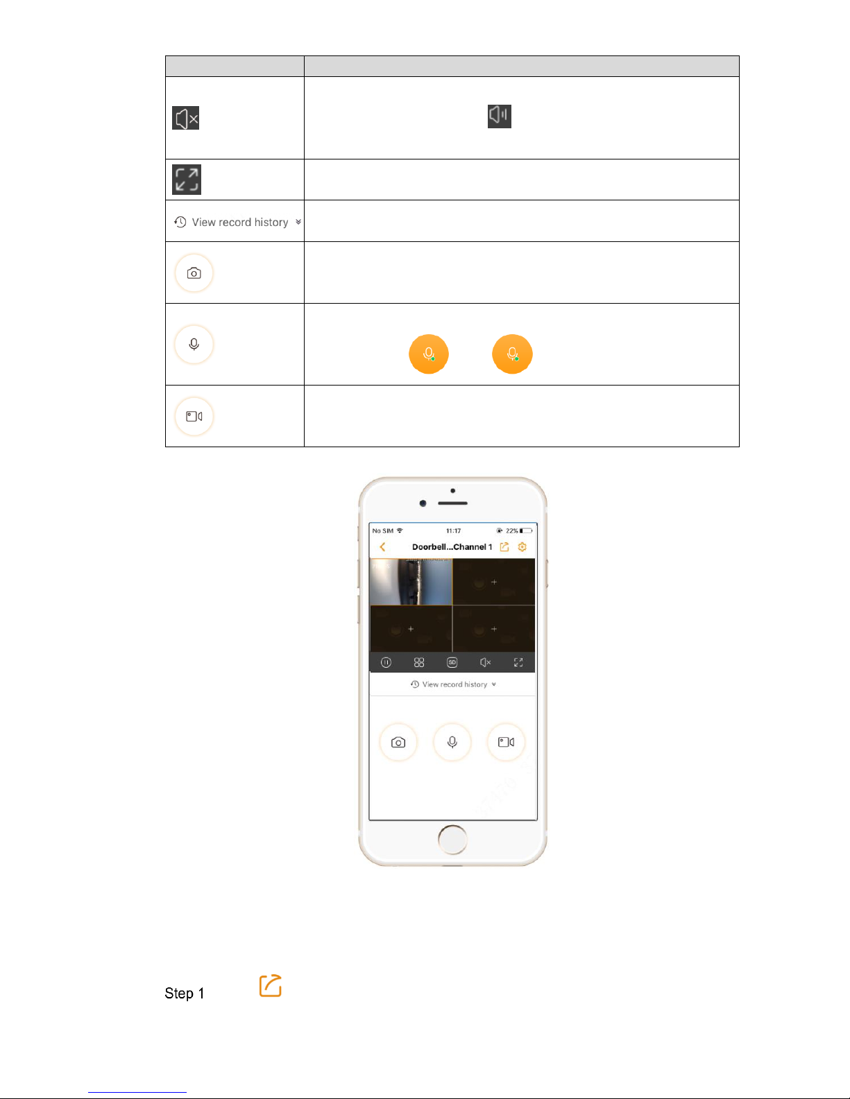
3.4 Monitoring
Press a picture under a serial number in the device list, and open doorbell monitoring interface,
as shown in Figure 3-15. Preview the real-time videos. Please refer to Table 3-2 for details.
Page 25

15
Figure 3-15
Key
Note
This is share icon to realize device share and live share. Please refer
to “3.4.1 Live Share” for details.
This is device setup icon to view and set the device info. Please refer
to “5.1 Device Management” for details.
This play icon means that real-time video is being played.
Press this icon to switch to , and the video is paused.
Under the status of multi-image preview, please select the image
before operation.
Single image icon means that single image is displayed at present.
Press this icon to switch to and the interface displays
four-image preview, as shown in Figure 3-16. Press to add
preview device.
It means that present video is standard-definition (SD) status. Press
this icon to switch to high-definition (HD) status, and it turns to .
Press again to switch to SD status.
Under the status of multi-image preview, please select the image
before operation.
Page 26
16
Key
Note
Mute icon means that the present channel is mute.
Press this icon to switch to . In case of audio input at doorbell,
audio will be played.
Full screen icon realizes full-screen preview. Please refer to “3.4.2
Full-screen Preview” for details.
View alarm records at cloud server or SD card. Please refer to “3.4.3
View Alarm Records” for details.
Press this key to get a screenshot of the video, and save the picture in
APP local file.
It is in audio talking status. Press this key to turn off audio talking, and
this key turns to ; press again to enable audio talking.
Press this key to start recording. Recording time is displayed at the
upper left corner of the interface. Press it again to stop recording, and
save recording file in APP local file.
Table 3-2
Figure 3-16
3.4.1 Live Share
Press “ > Live Share”. A prompt box pops up.
Page 27

17
Press [OK]. “Share time setup” pops up at the bottom, as shown in Figure 3-17.
Figure 3-17
Select share time and press [OK].
Press to copy the link and paste it to a social platform.
The video can be opened and previewed at the platform in a real-time way.
3.4.2 Full-screen Preview
Press , and full-screen preview status is displayed, as shown in Figure 3-18.
Figure 3-18
3.4.3 View Alarm Records
Press .
Page 28

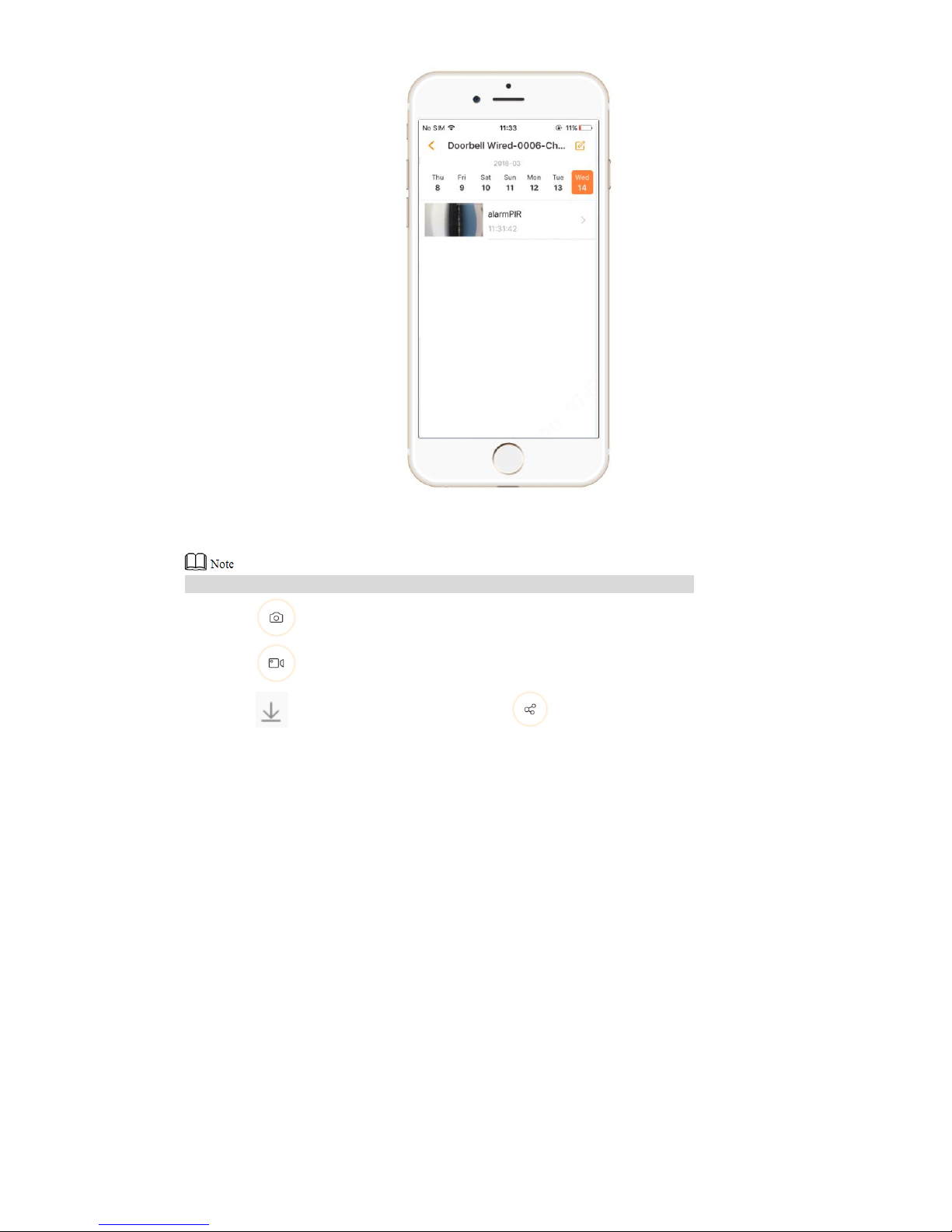
18
The system displays record history interface, as shown in Figure 3-19.
Figure 3-19
Press or to select the location.
: view alarm records in SD card.
: view alarm records at cloud server.
Select the date.
Slide the time axis or picture, select the record and start to play the record.
When playing the record in full screen, realize screenshot of the video, record again
and switch the position.
Page 29

19
4 Device Installation
Before installation, please ensure that the device has been added. Please refer to “3.2 Add
Device” for details.
Loosen M3×6 screws at the bottom of the device, and dismantle the installation bracket
from the device.
Drill holes in the wall according to screw hole and cable outlet positions of installation
bracket, and install plastic expansion pipes.
Connect power and chime cables; lead them out of cable outlet of the bracket.
Please refer to “2.2.2 Description of Power Input Port” for details.
Fix the bracket onto the wall with three ST3×20 self-tapping screws.
Put the device into the slot at the top of the bracket from top to bottom.
Fix the device onto the bracket with M3×6 screws.
Figure 4-1
Page 30
20
5 APP Operation
5.1 Device Management
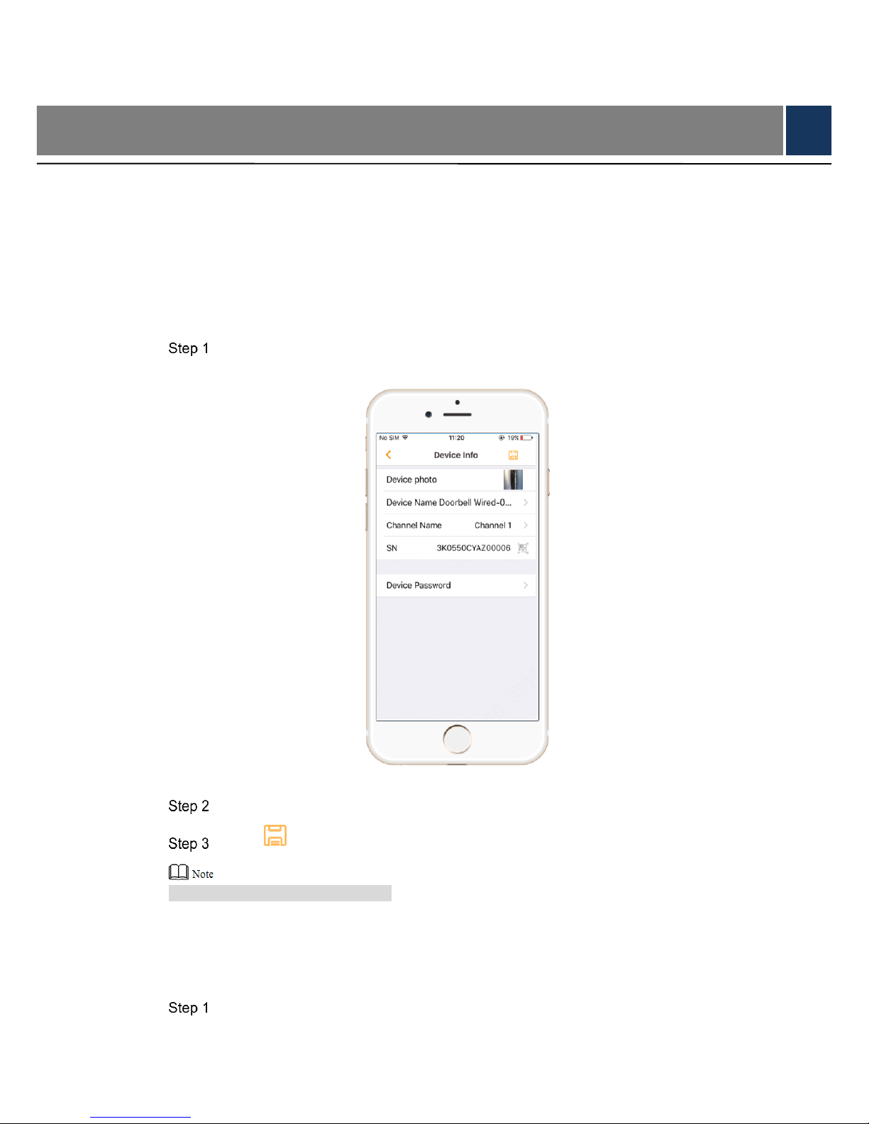
5.1.1 Modify Device Info
Modify device photo, device name and channel name; view its SN and set device password.
Select “Me> My Device > Device Name > Device Name”.
The system displays “Device Info” interface, as shown in Figure 5-1.
Figure 5-1
Modify the parameters according to needs.
Press to save the setups.
By default, “Device Name” is its SN.
5.1.2 Modify Device Password
Modify admin password.
Select “Me> My Device > Device Name > Device Name”.
The system displays “Device Info” interface, as shown in Figure 5-1.
Page 31

21
Press [Device Password].
The system displays “Device Password” interface, as shown in Figure 5-2.
Figure 5-2
Enter “Old Password”, “New Password” and “Confirm Password”; press .
5.1.3 Link Chime
Link the doorbell with chime.
Select “Me> My Device > Device Name > Link Chime” or click in device menu.
The system displays “Link Chime” interface, as shown in Figure 5-3.
Page 32

22
Figure 5-3
Select “New Link”.
The system displays wireless chime list, as shown in Figure 5-4.
Figure 5-4
To link wireless chime, select it from the list.
To link third-party chime, press [Link Third Party Chime], and the system displays
chime type selection interface, as shown in Figure 5-5. Select a type, press [OK],
and the system will automatically read the connected chime info.
Page 33

23
Figure 5-5
Press [Save] to complete adding.
5.1.4 Ring Setup
Set the chime ring.
Select “Me> My Device > Device Name > Link Chime” or click in device menu.
The system displays “Link Chime” interface, as shown in Figure 5-6.
Page 34

24
Figure 5-6
Select “Ring Setup”.
The system displays ring list, as shown in Figure 5-7. A, B and C represent ring A, ring
B and ring C.
Figure 5-7
Select a ring, and press [Save] to complete adding.
5.1.5 Set PIR Motion Detection Zone
After setting PIR motion detection zone, a motion detection alarm will be sent if an object
moves in the zone.
Select “Me> My Device > Device Name > PIR Zone”.
The system displays zone setup interface, as shown in Figure 5-8.
Figure 5-8
Set PIR motion detection zone and distance.
Press zone block to enable or disable PIR motion detection of this zone.
Slide the dot in the left; adjust far/near detection distance of the zone.
Page 35

25
Detection range of the device is horizontal 120°, which is divided into 3 zones.
Press [Save] to save the setup.
5.1.6 Enable Alarm Info
After it is enabled, PIR motion detection alarm will be sent to APP.
Select “Me> My Device > Device Name >Alarm”.
The system displays “Alarm” interface, as shown in Figure 5-9.
Figure 5-9
Press .
Enable it to send info to APP. The key turns to .
5.1.7 Set Storage Status
Enable cloud storage function and view SD card capacity.
If cloud storage is enabled, records or pictures will be stored at cloud server.
If cloud storage is not enabled and SD card is inserted into the device, records or pictures
will be stored in SD card.
It is suggested that cloud storage function should be enabled.
5.1.7.1 Cloud Storage
APP comes with a one-month free trial of cloud storage, one channel for one account. After
Page 36

26
enabling this function, pictures or record files will be stored at cloud server automatically.
Select “Me> My Device > Device Name >Storage Status > Cloud Storage > Channel Name”;
select the item to buy it.
5.1.7.2 SD Card Storage
If cloud storage is not enabled, insert SD card, so records or pictures will be stored in SD card
automatically.
Select “Me> My Device > Device Name >Storage Status”, as shown in Figure 5-10.
Press [Device Storage] to view the capacity utilization status of SD card.
Press [Format Storage Device] to format the SD card.
Figure 5-10
5.1.8 Set Time Zone
Set local time zone and DST, ensure snapshot and recording time points are consistent with
local time points, so as to search and view conveniently.
Select “Me> My Device > Device Name > Time Zone”.
The system displays “Time Zone” interface, as shown in Figure 5-11.
Page 37

27
Figure 5-11
Press “Time Zone” to select local time zone.
(Optional) press to enable DST; set “Start Time” and “End Time”.
Press to save the setup.
5.1.9 Set Image Flip
Vertically flip the video image at real-time preview interface.
Select “Me> My Device > Device Name”.
Press in image flip parameter to enable flip.
5.1.10 Set Device Share
At present, APP supports to share preview, screenshot and record functions, while call push
and PIR functions are being improved. Please pay attention to APP update notice.
5.1.11 Cloud Update
After entering the update interface, update the device to the latest version.
Select “Me> My Device > Device Name > Update”.
The system displays “Update” interface, as shown in Figure 5-12.
Page 38

28
Figure 5-12
Press [Update].
Update the device according to interface prompt. The device reboots automatically
after successful update.
5.1.12 Modify Wi-Fi Config
Modify Wi-Fi config of the device, in order to connect with other Wi-Fi networks.
Select “Me> My Device > Device Name > Wi-Fi Config”.
The system displays “Wi-Fi Config” interface, as shown in Figure 5-13.
Page 39

29
Figure 5-13
Select new Wi-Fi and enter the password.
Figure 5-14
Press to connect new Wi-Fi network.
5.1.13 Delete Device
Select “Me> My Device > Device Name > Delete Device”, so as to unbind the device.
Page 40

30
5.2 Settings
5.2.1 Prompt
After prompt function is enabled, be able to receive prompts when APP is closed, such as call
not answered, PIR and low battery.
Select “Me> Settings”.
The system displays “Settings” interface, as shown in Figure 5-15.
Figure 5-15
Press to enable prompt function.
Press [Period] to set “Start Time” and “End Time”.
5.3 View Message
5.3.1 APP is Online
View alarm messages, such as PIR, low battery, call not answered, version info update and
emergency prompt.
When APP is online, select “Message”, as shown in Figure 5-16.
Page 41

31
Figure 5-16
Select “System” to view APP version update and emergency prompt, as shown in Figure 5-17.
Figure 5-17
Select device channel in the list, to view messages such as PIR, low battery and call not
answered of the channel, as shown in Figure 5-18.
Page 42
32
Figure 5-18
Select one message to view the content, as shown in Figure 5-19.
In case of cloud storage, it is able to view records in the recent 7 days only.
Click to make a snapshot of the picture.
Click to clip records.
Click to download the records. Click to share the records with others.
Page 43

33
Figure 5-19
5.3.2 APP is Closed
In case of PIR and call not answered alarms when APP is closed, notify in the form of prompts,
as shown in Figure 5-20.
Figure 5-20
In case of PIR or call not answered prompt, press this prompt to view videos and snapshots.
5.4 View Local Files
View snapshots and videos.
Select “Me >Local File”, as shown in Figure 5-21.
Press , switch to interface of picture list, select a picture and zoom in to view its
content.
Press , switch to interface of record list, select a record and play black it.
Page 44

34
Figure 5-21
Page 45

35
6 FAQ
Q: The device cannot boot up?
A: Please confirm whether power voltage of the device is normal, and whether power cable is
well connected.
Q: Connection is overtime?
A: a. The device, mobile phone and router are too far away. Please put them within 30cm (12
inches) when configuring.
b. Please reset the device to factory defaults and follow the guide on App page to try again.
Q: The device is not online?
A: Please check the state of device indicator light. If blue light flickers all the time, it means that
the device fails to connect the network. Please check whether wireless router can connect
the network; connect your mobile phone with this wireless network to test it. If it can connect
the network, please reset the device and configure again.
Q: How to upgrade the firmware?
A: Enter “Me > My Device” to find the device, and view cloud upgrade menu. If there is new
program prompt (a red dot), click to enter upgrade interface. The device will be rebooted
automatically after upgrade.
Q: There is no message when PIR motion detection is triggered?
A: a. Please check whether alarm subscription is enabled.
b. If it is enabled, please check whether corresponding PIR zone is enabled.
c. Please check whether zone detection distance is set to be a relatively small range.
Q: How to restore factory settings?
A: Please press Reset Button on the rear panel of the device for 5s. Blue light will be on for 3s
and then turn off; the device will reboot automatically and restore factory default settings.
Page 46

36
Technical Parameters
Parameter
Note
Power Supply
AC 16V–24V or DC12V–24V
Power Consumption
Less than 5W during normal work
Dimension
119mm×47mm×26mm
Weight
200g
Operating Temperature
Recommended -10℃~+50℃
Appendix Table 1-1
 Loading...