

Page 1

DIGITAL VIDEO RECORDER
User’s Manual
V1.0.0
Page 2

Cybersecurity Recommendations I
Cybersecurity Recommendations
Mandatory actions to be taken towards cybersecurity
1. Change Passwords and Use Strong Passwords:
The number one reason systems get “hacked” is due to having weak or default passwords. It is
recommended to change default passwords immediately and choose a strong password whenever
possible. A strong password should be made up of at least 8 characters and a combination of special
characters, numbers, and upper and lower case letters.
2. Update Firmware
As is standard procedure in the tech-industry, we recommend keeping NVR, DVR, and IP camera
firmware up-to-date to ensure the system is current with the latest security patches and fixes.
“Nice to have” recommendations to improve your network security
1. Change Passwords Regularly
Regularly change the credentials to your devices to help ensure that only authorized users are able to
access the system.
2. Change Default HTTP and TCP Ports:
● Change default HTTP and TCP ports for systems. These are the two ports used to communicate and
to view video feeds remotely.
● These ports can be changed to any set of numbers between 1025-65535. Avoiding the default ports
reduces the risk of outsiders being able to guess which ports you are using.
3. Enable HTTPS/SSL:
Set up an SSL Certificate to enable HTTPS. This will encrypt all communication between your devices
and recorder.
4. Enable IP Filter:
Enabling your IP filter will prevent everyone, except those with specified IP addresses, from accessing
the system.
5. Change ONVIF Password:
On older IP Camera firmware, the ONVIF password does not change when you change the system’s
credentials. You will need to either update the camera’s firmware to the latest revision or manually
change the ONVIF password.
6. Forward Only Ports You Need:
● Only forward the HTTP and TCP ports that you need to use. Do not forward a huge range of numbers
to the device. Do not DMZ the device's IP address.
● You do not need to forward any ports for individual cameras if they are all connected to a recorder on
site; just the NVR is needed.
7. Disable Auto-Login on SmartPSS:
Those using SmartPSS to view their system and on a computer that is used by multiple people should
disable auto-login. This adds a layer of security to prevent users without the appropriate credentials from
accessing the system.
8. Use a Different Username and Password for SmartPSS:
Page 3

Cybersecurity Recommendations II
In the event that your social media, bank, email, etc. account is compromised, you would not want
someone collecting those passwords and trying them out on your video surveillance system. Using a
different username and password for your security system will make it more difficult for someone to
guess their way into your system.
9. Limit Features of Guest Accounts:
If your system is set up for multiple users, ensure that each user only has rights to features and functions
they need to use to perform their job.
10. UPnP:
● UPnP will automatically try to forward ports in your router or modem. Normally this would be a good
thing. However, if your system automatically forwards the ports and you leave the credentials defaulted,
you may end up with unwanted visitors.
● If you manually forwarded the HTTP and TCP ports in your router/modem, this feature should be
turned off regardless. Disabling UPnP is recommended when the function is not used in real
applications.
11. SNMP:
Disable SNMP if you are not using it. If you are using SNMP, you should do so only temporarily, for
tracing and testing purposes only.
12. Multicast:
Multicast is used to share video streams between two recorders. Currently there are no known issues
involving Multicast, but if you are not using this feature, deactivation can enhance your network security.
13. Check the Log:
If you suspect that someone has gained unauthorized access to your system, you can check the system
log. The system log will show you which IP addresses were used to login to your system and what was
accessed.
14. Physically Lock Down the Device:
Ideally, you want to prevent any unauthorized physical access to your system. The best way to achieve
this is to install the recorder in a lockbox, locking server rack, or in a room that is behind a lock and key.
Page 4
Foreword III
Foreword
General
This user’s manual (hereinafter referred to be "the Manual") introduces the functions and
operations of the DVR devices (hereinafter referred to be "the Device").
DVR Models
Smart 1U, E Model, Compact 1U, Mini 1U, 1U
Safety Instructions
The following categorized signal words with defined meaning might appear in the Manual.
Signal Words
Meaning
Indicates a high potential hazard which, if not avoided, will result
in death or serious injury.
Indicates a medium or low potential hazard which, if not avoided,
could result in slight or moderate injury.
Indicates a potential risk which, if not avoided, may result in
property damage, data loss, lower performance, or unpredictable
result.
Provides methods to help you solve a problem or save you time.
Provides additional information as the emphasis and supplement
to the text.
Revision History
No.
Version
Revision Content
Release Time
1
V1.0.0
First Release.
January 31, 2018
About the Manual
The Manual is for reference only. If there is inconsistency between the Manual and the
actual product, the actual product shall govern.
All the designs and software are subject to change without prior written notice. The product
updates might cause some differences between the actual product and the Manual. Please
contact the customer service for the latest program and supplementary documentation.
Page 5

Foreword IV
There still might be deviation between the actual value of some data and the value
provided, if there is any doubt or dispute, please refer to our final explanation.
Please contact the supplier or customer service if there is any problem occurred when
using the device.
We are not liable for any loss caused by the operations that do not comply with the Manual.
All trademarks, registered trademarks and the company names in the Manual are the
properties of their respective owners.
Please visit our website or contact your local service engineer for more information.
If there is any uncertainty or controversy, please refer to our final explanation.
Page 6

Important Safeguards and Warnings V
Important Safeguards and Warnings
Electrical safety
All installation and operation here should conform to your local electrical safety codes.
The product must be grounded to reduce the risk of electric shock.
We assume no liability or responsibility for all the fires or electrical shock caused by improper
handling or installation.
Transportation security
Heavy stress, violent vibration or water splash are not allowed during transportation, storage
and installation.
Installation
Keep upwards. Handle with care.
Do not apply power to the Device before completing installation.
Do not place objects on the Device.
Qualified engineers needed
All the examination and repair work should be done by the qualified service engineers. We are
not liable for any problems caused by unauthorized modifications or attempted repair.
Environment
The Device should be installed in a cool, dry place away from conditions such as direct sunlight,
inflammable substances, and explosive substances.
Accessories
Be sure to use all the accessories recommended by manufacturer.
Before installation, please open the package and check all the components are included.
Contact your local retailer ASAP if something is broken in your package.
Lithium battery
Improper battery use might result in fire, explosion, or personal injury.
When replacing the battery, please make sure you are using the same type. Risk of
explosion if battery is replaced by an incorrect type.
Dispose of used batteries according to the instructions.
Page 7

Table of Contents VI
Table of Contents
Cybersecurity Recommendations ........................................................................................................... I
Foreword .................................................................................................................................................. III
Important Safeguards and Warnings ..................................................................................................... V
1 Introduction ............................................................................................................................................ 1
1.1 Overview ........................................................................................................................................ 1
1.2 Functions ....................................................................................................................................... 1
2 Getting Started ...................................................................................................................................... 3
2.1 Checking the Components ............................................................................................................ 3
2.2 Installing HDD ................................................................................................................................ 3
2.2.1 Smart 1U ............................................................................................................................. 4
2.2.2 E Model ............................................................................................................................... 5
2.2.3 MINI 1U and Compact 1U .................................................................................................. 6
2.2.4 1U ....................................................................................................................................... 6
2.3 Installing Device into Rack ............................................................................................................ 7
3 The Grand Tour ...................................................................................................................................... 8
3.1 Front Panel .................................................................................................................................... 8
3.1.1 Smart 1U ............................................................................................................................. 8
3.1.2 E Model ............................................................................................................................... 9
3.1.3 Compact 1U ........................................................................................................................ 9
3.1.4 MINI 1U ............................................................................................................................. 10
3.1.5 1U ..................................................................................................................................... 10
3.2 Rear Panel .................................................................................................................................... 11
3.2.1 Smart 1U ............................................................................................................................ 11
3.2.2 E Model .............................................................................................................................. 11
3.2.3 Compact 1U ...................................................................................................................... 12
3.2.4 MINI 1U ............................................................................................................................ 13
3.2.5 1U ..................................................................................................................................... 15
3.3 Remote Control Operations ......................................................................................................... 16
3.4 Mouse Operations ....................................................................................................................... 17
4 Connecting Basics .............................................................................................................................. 19
4.1 Typical Connection Diagram ....................................................................................................... 19
4.2 Connecting to Video and Audio Input and Output ....................................................................... 21
4.2.1 Video Input ........................................................................................................................ 21
4.2.2 Video Output ..................................................................................................................... 21
4.2.3 Audio Input ........................................................................................................................ 22
4.2.4 Audio Output ..................................................................................................................... 22
4.3 Connecting to Alarm Input and Output ........................................................................................ 22
4.3.1 Introducing Alarm Port ...................................................................................................... 23
4.3.2 Alarm Input ........................................................................................................................ 23
4.3.3 Alarm Output ..................................................................................................................... 24
4.3.4 Alarm Output Relay Parameters ....................................................................................... 24
Page 8

Table of Contents VII
4.4 Connecting to RS485 Port ........................................................................................................... 25
4.5 Replacing Battery ........................................................................................................................ 25
5 Local Configurations .......................................................................................................................... 26
5.1 Initial Settings .............................................................................................................................. 26
5.1.1 Booting up ......................................................................................................................... 26
5.1.2 Initializing the Device ........................................................................................................ 26
5.1.3 Resetting Password .......................................................................................................... 29
5.1.4 Setting Up with the Startup Wizard .................................................................................. 34
5.2 Live View ..................................................................................................................................... 51
5.2.1 Live View Screen .............................................................................................................. 52
5.2.2 Live View Control bar ........................................................................................................ 53
5.2.3 Navigation Bar .................................................................................................................. 56
5.2.4 Shortcut Menu .................................................................................................................. 57
5.2.5 Color Setting ..................................................................................................................... 59
5.2.6 Live View Display .............................................................................................................. 61
5.2.7 Configuring Tour Settings ................................................................................................. 66
5.3 Entering Main Menu .................................................................................................................... 69
5.4 Controlling PTZ Cameras ............................................................................................................ 72
5.4.1 Configuring PTZ Connection Settings .............................................................................. 72
5.4.2 Working with PTZ Control Panel ...................................................................................... 74
5.4.3 Configuring PTZ Functions ............................................................................................... 76
5.4.4 Calling PTZ Functions ...................................................................................................... 78
5.4.5 Calling OSD Menu ............................................................................................................ 79
5.5 Configuring Camera Settings ...................................................................................................... 80
5.5.1 Configuring Image Settings .............................................................................................. 80
5.5.2 Configuring Encode Settings ............................................................................................ 83
5.5.3 Configuring Snapshot Settings ......................................................................................... 85
5.5.4 Configuring Overlay Settings ............................................................................................ 86
5.5.5 Configuring Covered Area Settings .................................................................................. 87
5.5.6 Configuring Channel Type ................................................................................................ 88
5.5.7 Upgrading Coaxial Camera .............................................................................................. 89
5.6 Configuring Remote Devices ....................................................................................................... 90
5.6.1 Adding Remote Devices ................................................................................................... 90
5.6.2 Managing Remote Devices ............................................................................................ 101
5.7 Configuring Record Settings ..................................................................................................... 104
5.7.1 Enabling Record Control ................................................................................................ 105
5.7.2 Configuring Recorded Video Storage Schedule ............................................................ 106
5.8 Configuring Snapshot Settings .................................................................................................. 106
5.8.1 Configuring Snapshot Trigger ......................................................................................... 106
5.8.2 Configuring Snapshot Storage Schedule ........................................................................ 111
5.8.3 Backing up Snapshots to FTP ......................................................................................... 111
5.9 Playing Back Video .....................................................................................................................112
5.9.1 Enabling Record Control .................................................................................................112
5.9.2 Instant Playback ..............................................................................................................113
5.9.3 Main Interface of Video Playback ....................................................................................113
5.9.4 Smart Search ...................................................................................................................118
5.9.5 Marking and Playing Back Video .....................................................................................119
Page 9

Table of Contents VIII
5.9.6 Playing Back Snapshots ................................................................................................. 121
5.9.7 Playing Back Splices ...................................................................................................... 121
5.9.8 Using the File List ........................................................................................................... 122
5.10 Alarm Events Settings ............................................................................................................. 124
5.10.1 Video Detection ............................................................................................................ 124
5.10.2 IVS Function ................................................................................................................. 133
5.10.3 Face Detection .............................................................................................................. 146
5.10.4 System Events .............................................................................................................. 149
5.10.5 Alarm Input Settings ..................................................................................................... 155
5.10.6 Alarm Output Settings ................................................................................................... 162
5.11 IoT Function ............................................................................................................................. 163
5.11.1 Configuring Sensor Settings ......................................................................................... 163
5.11.2 Configuring Temperature and Humidity Camera .......................................................... 170
5.11.3 Configuring Wireless Siren ........................................................................................... 182
5.12 Configuring POS Settings ........................................................................................................ 183
5.12.1 Searching the Transaction Records ............................................................................. 183
5.12.2 Configuring POS Settings ............................................................................................. 184
5.13 Configuring Backup Settings ................................................................................................... 185
5.13.1 Finding USB Device ..................................................................................................... 185
5.13.2 Backing up Files ........................................................................................................... 186
5.14 Network Management.............................................................................................................. 187
5.14.1 Configuring Network Settings ....................................................................................... 187
5.14.2 Configuring Network Testing Settings .......................................................................... 202
5.15 Configuring Account Settings .................................................................................................. 206
5.15.1 Configuring User Account ............................................................................................. 206
5.15.2 Configuring Group Account .......................................................................................... 212
5.15.3 Configuring Onvif Users ............................................................................................... 216
5.16 Audio Management .................................................................................................................. 217
5.16.1 Configuring Audio Files ................................................................................................. 217
5.16.2 Configuring Playing Schedule for Audio Files .............................................................. 219
5.17 Storage Management .............................................................................................................. 221
5.17.1 Configuring Basic Settings ........................................................................................... 221
5.17.2 Configuring the Recording and Snapshot Schedule .................................................... 222
5.17.3 Configuring HDD Manager ........................................................................................... 222
5.17.4 Configuring HDD Group ............................................................................................... 223
5.17.5 Configuring HDD Detecting Settings ............................................................................ 225
5.17.6 Configuring Quota Settings .......................................................................................... 229
5.17.7 Configuring Record Estimate ....................................................................................... 231
5.17.8 Configuring FTP Storage Settings ................................................................................ 233
5.18 Configuring System Settings ................................................................................................... 235
5.18.1 Configuring General System Settings .......................................................................... 235
5.18.2 Configuring RS232 Port Settings ................................................................................. 236
5.18.3 Configuring Security Settings ....................................................................................... 238
5.18.4 Configuring System Maintenance Settings .................................................................. 239
5.18.5 Exporting and Importing System Settings .................................................................... 240
5.18.6 Restoring Default Settings ............................................................................................ 242
5.18.7 Upgrading the Device ................................................................................................... 243
Page 10

Table of Contents IX
5.19 Viewing Information ................................................................................................................. 246
5.19.1 Viewing Version Details ................................................................................................ 246
5.19.2 Viewing Log Information ............................................................................................... 247
5.19.3 Viewing Event Information ............................................................................................ 249
5.19.4 Viewing Network Information ........................................................................................ 250
5.19.5 Viewing HDD Information ............................................................................................. 252
5.19.6 Viewing Device Status .................................................................................................. 253
5.19.7 Viewing Channel Information ........................................................................................ 254
5.19.8 Viewing Data Stream Information ................................................................................. 255
5.20 Logout the Device .................................................................................................................... 256
6 Web Operations ................................................................................................................................. 257
6.1 Connecting to Network .............................................................................................................. 257
6.2 Logging in the Web .................................................................................................................... 257
6.3 Resetting Password ................................................................................................................... 258
6.4 Introducing Web Main Menu ..................................................................................................... 261
7 FAQ ..................................................................................................................................................... 263
Glossary ............................................................................................................................ 269
HDD Capacity Calculation .............................................................................................. 271
Compatible Backup Devices .......................................................................................... 273
Appendix 3.1 Compatible USB list .................................................................................................. 273
Appendix 3.2 Compatible SD Card list ........................................................................................... 274
Appendix 3.3 Compatible Portable HDD list ................................................................................... 274
Appendix 3.4 Compatible USB DVD List ........................................................................................ 274
Appendix 3.5 Compatible SATA DVD List ....................................................................................... 274
Appendix 3.6 Compatible SATA HDD List ...................................................................................... 275
Compatible CD/DVD Burner List .................................................................................... 280
Compatible Displayer List .............................................................................................. 281
Compatible Switcher ....................................................................................................... 282
Earthing ........................................................................................................................... 283
Appendix 7.1 What Is the Surge ..................................................................................................... 283
Appendix 7.2 The Earthing Modes ................................................................................................. 284
Appendix 7.3 Thunder Proof Ground Method in the Monitor System ............................................ 285
Appendix 7.4 The Shortcut Way to Check the Electric System by Digital Multimeter .................... 286
RJ45-RS232 Connection Cable Definition .................................................................. 289
Page 11

Introduction 1
1 Introduction
1.1 Overview
The Device is an excellent digital monitor product for security industry. The embedded LINUX
OS assures the stable operation. The H.264 and G.711 technologies assure the high quality
image and low bit stream. The frame-by-frame play function displays more details for analysis,
and provides the functions such as record, playback, and monitor and assures the
synchronization for audio and video. The Device also adopts the advanced control technology
and great network data transmission capability.
The Device adopts embedded design to achieve high security and reliability. It can work in the
local end and, with strong networking capability it can get connected to the professional
surveillance software (Smart PSS) to form a security network to show its powerful remote
monitoring function.
The Device is applicable to the areas such as bank, telecom, electricity, traffic, intelligent
residential district, factory, warehouse, resources, and water conservancy facilities.
1.2 Functions
The functions might be different depending on the software and hardware version of the model
you purchased.
Real-time Surveillance
Support VGA port and HDMI port to realize the surveillance through monitors.
Support HDMI, VGA, and TV output at the same time.
IoT Management
Provide specific management module for IoT features including humidity and temperature data
reports and alarms linkage.
Sensor Integration
Integrate coaxial cameras with diverse array of sensors such as temperature, humidity and
wireless alarm devices.
Storage Management
Special data format to guarantee data security and avoid the risk of modifying data
viciously.
Support digital watermark.
Compression Format
Page 12

Introduction 2
Support multiple-channel audio and video signal. An independent hardware decodes the audio
and video signal from each channel to maintain video and audio synchronization.
Backup Function
Support backup operation through USB port (such as USB storage disk, portable HDD,
and burner).
Client-end user can download the file from local HDD through network to backup.
Record & Playback
Support each channel real-time record independently, and simultaneously support the
functions such as search, backward play, network monitor, record search, and download.
Support various playback modes: slow play, fast play, backward play and frame by frame
play.
Support time title overlay so that you can view event accurate occurred time.
Support zooming in the selected area in the live view.
Network Operation
Support network remote real-time monitor, remote record search and remote PTZ control.
Alarm Activation
Several relay alarm outputs to realize alarm activation and on-site light control.
The alarm input port and output port have the protection circuit to guarantee the Device
safety.
Communication Port
RS485 port can realize alarm input and PTZ control.
RS232 port can connect to keyboard, COM port of PC or the matrix control.
Standard Ethernet port can realize network remote access function.
The dual-network port has the multiple-address, fault tolerance, load balance setup mode.
PTZ Control
Support PTZ decoder through RS485 port.
Intelligent Operation
Support mouse operation function.
Support "copy and paste" function for the same settings.
UPnP (Universal Plug and Play)
Establish mapping connection between LAN and WAN through UPnP protocol.
Camera Self-adaptive
Auto-recognize and work with the PAL or NTSC camera and HD camera.
Page 13
Getting Started 3
2 Getting Started
2.1 Checking the Components
When you receive the Device, please check against the following checking list. If any of the
items are missing or damaged, contact the local retailer or after-sales engineer immediately.
Sequence
Checking items
Requirement
1
Package
Appearance
No obvious damage.
Packing materials
No broken or distorted positions that
could be caused by hit.
2
Labels
Labels on the device
Not torn up.
Do not tear up or throw away the
labels; otherwise the warranty
services are not ensured. You need
to provide the serial number of the
product when you call the after-sales
service.
3
Device
Appearance
No obvious damage.
Data cables, power
cables, fan cables,
mainboard
No connection loose.
2.2 Installing HDD
Please check if the HDD is already installed in the Device when you first time using the Device.
It is suggested to use the HDD recommended officially. Do not use the PC HDD.
Shut down the device and then unplug the power cable before you open the case to replace the
HDD.
Page 14
Getting Started 4
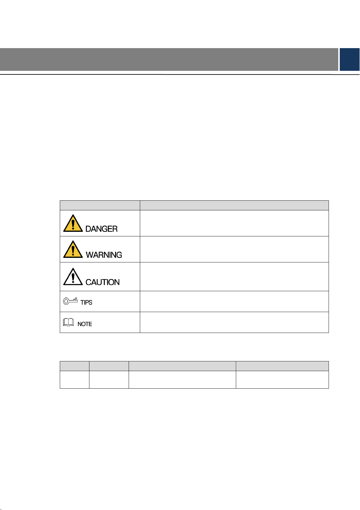
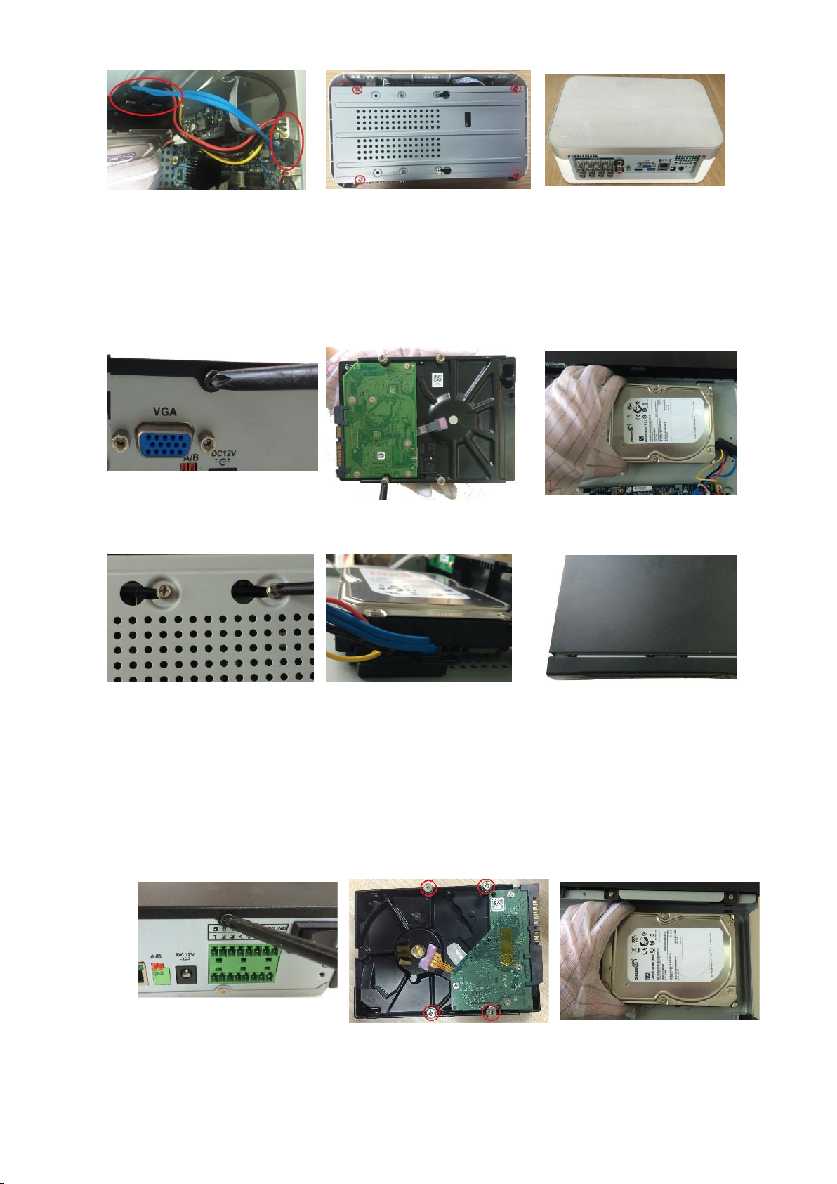
2.2.1 Smart 1U
1. Remove the screws to take
off the cover.
2. Fix the screws on the HDD
but do not fasten them.
3. Match the screws with
the holes on the DVR to
place the HDD.
4. Turn the DVR upside down
to see the screws and then
fasten them.
5. Use the HDD cable and
power cable to connect HDD
and mainboard.
6. Put back the cover and
fasten the screws.
Page 15
Getting Started 5
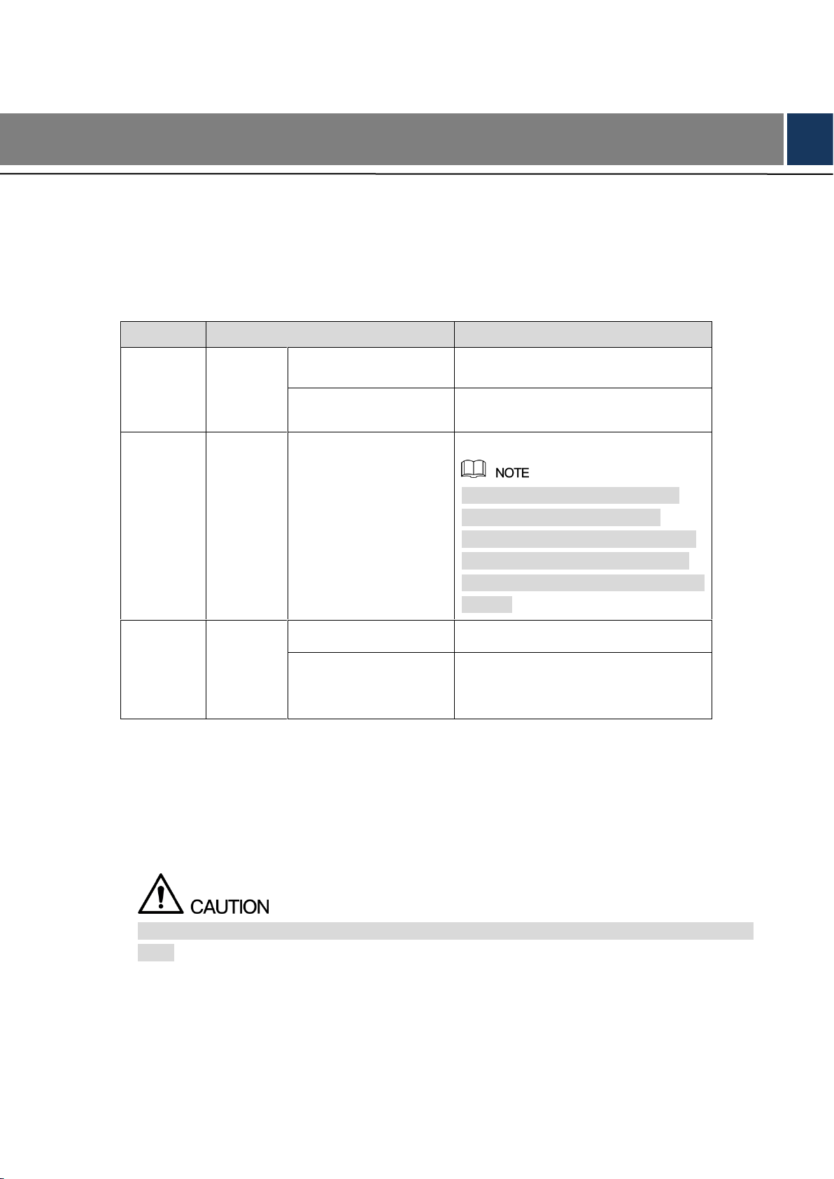
2.2.2 E Model
2.2.2.1 Installing Battery
The battery is only provided with some models.
1. Put the battery cable through the hole.
2. Connect to the cable into the port.
2.2.2.2 Installing HDD
Skip step 6 if the battery is not equipped with the model you purchased.
1. Remove the screws to take
off the cover.
2. Remove the screws to take
off the bracket.
3. Put the HDD onto the
bracket.
4. Match the holes on the
bracket with the screw
holes on HDD.
5. Use screws to fix the HDD
onto the bracket.
6. (Optional) Put the
battery cable through
the hole to connect into
the cable port.
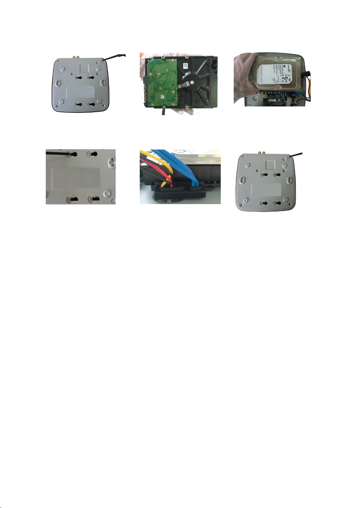
Page 16
Getting Started 6
7. Use the HDD cable and
power cable to connect
HDD and mainboard.
8. Install the bracket back and
then fasten the screws.
9. Put back the cover and
fasten the screws.
2.2.3 MINI 1U and Compact 1U
1. Remove the screws on the
rear panel.
2. Fix the screws on the HDD
but do not be fastened.
3. Place the HDD onto the
Device.
4. Turn the device to see the
back side of it. Aim the
screws of the HDD at the
holes on the back of the
device and fix the screws.
5. Use the HDD cable and
power cable to connect
HDD and mainboard.
6. Put back the cover and
fix the screws.
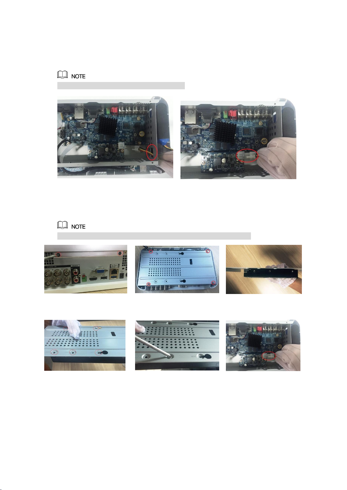
2.2.4 1U
1. Remove the screws on the
cover.
2. Fix the screws onto the
HDD, but do not be
fastened.
3. Put the HDD into the
Device.
Page 17
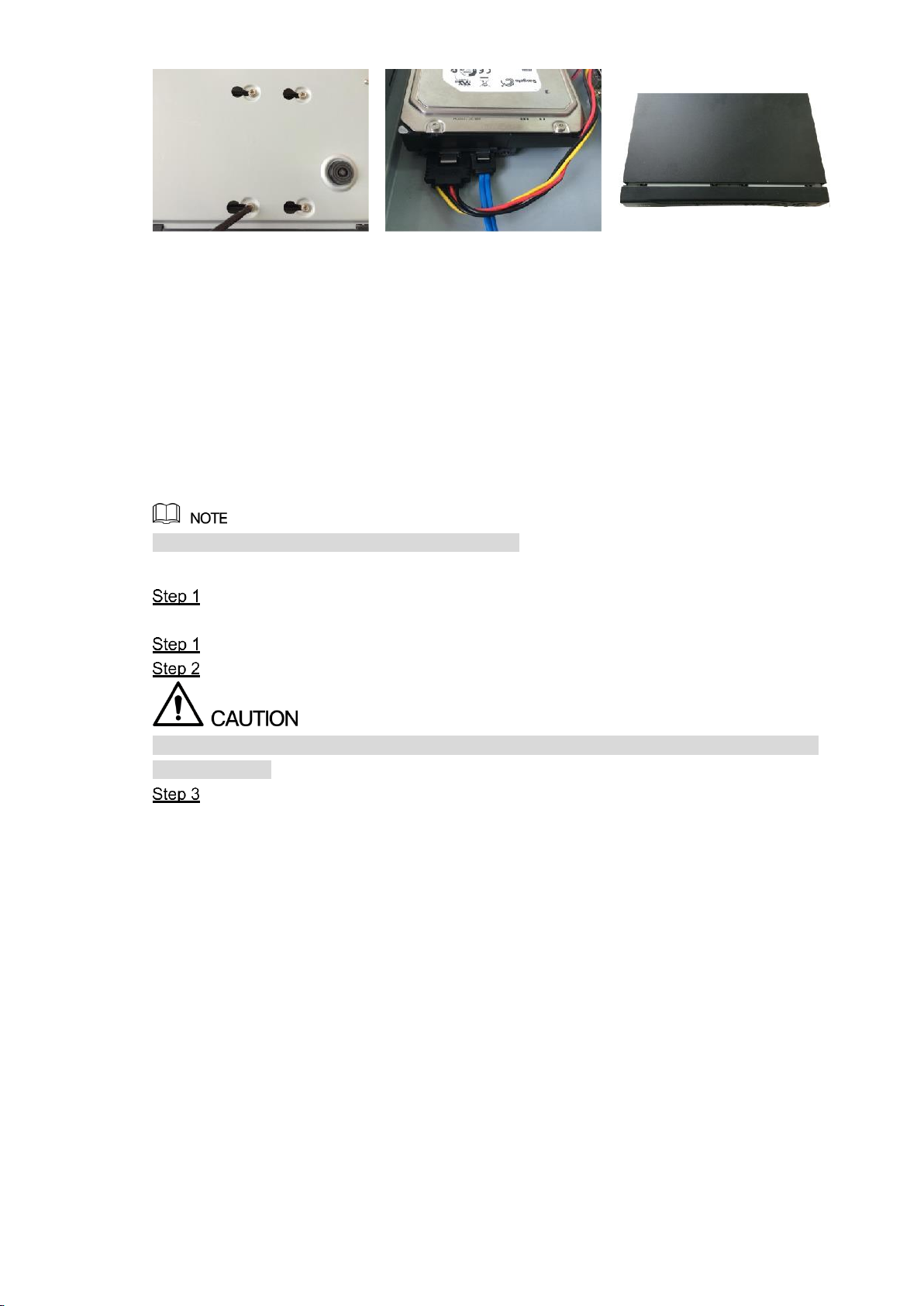
Getting Started 7
4. Turn the device to see the
back side of it. Aim the
screws of the HDD at the
holes on the back of the
device, and then fix the
screws.
5. Use the HDD cable and
power cable to connect
HDD and mainboard.
6. Put back the cover and fix
the screws.
2.3 Installing Device into Rack
Only 1.5U and 2U Devices support this installation.
To install the DVR into Rack, do the following:
Check if the in-house temperature is lower than 35℃(95℉) and make sure the 15cm
(6in.) spacing around the Device for ventilation.
Use six screws to fix the DVR on each side.
Install from the bottom up.
If you want to install more accessories to the rack, take preventive measures to avoid power
socket overload.
Install more accessories to the rack if needed.
Page 18
The Grand Tour 8
3 The Grand Tour
This chapter introduces various components of the Device, remote control and mouse
operations, and typical connection.
3.1 Front Panel
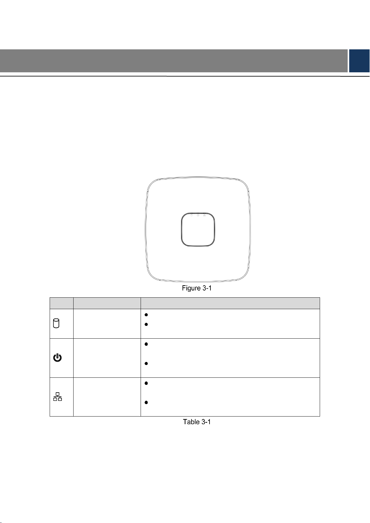
3.1.1 Smart 1U
Icon
Name
Function
HDD status indicator
The indicator is off when the HDD is running normally.
The indicator glows blue when the HDD is in
malfunction.
Power status
indicator
The indicator is off when the power is connected
abnormally.
The indicator glows blue when the power is connected
normally.
Network status
indicator
The indicator is off when the network connection is
correct.
The indicator glows blue when the network connection
is abnormal.
Page 19
The Grand Tour 9
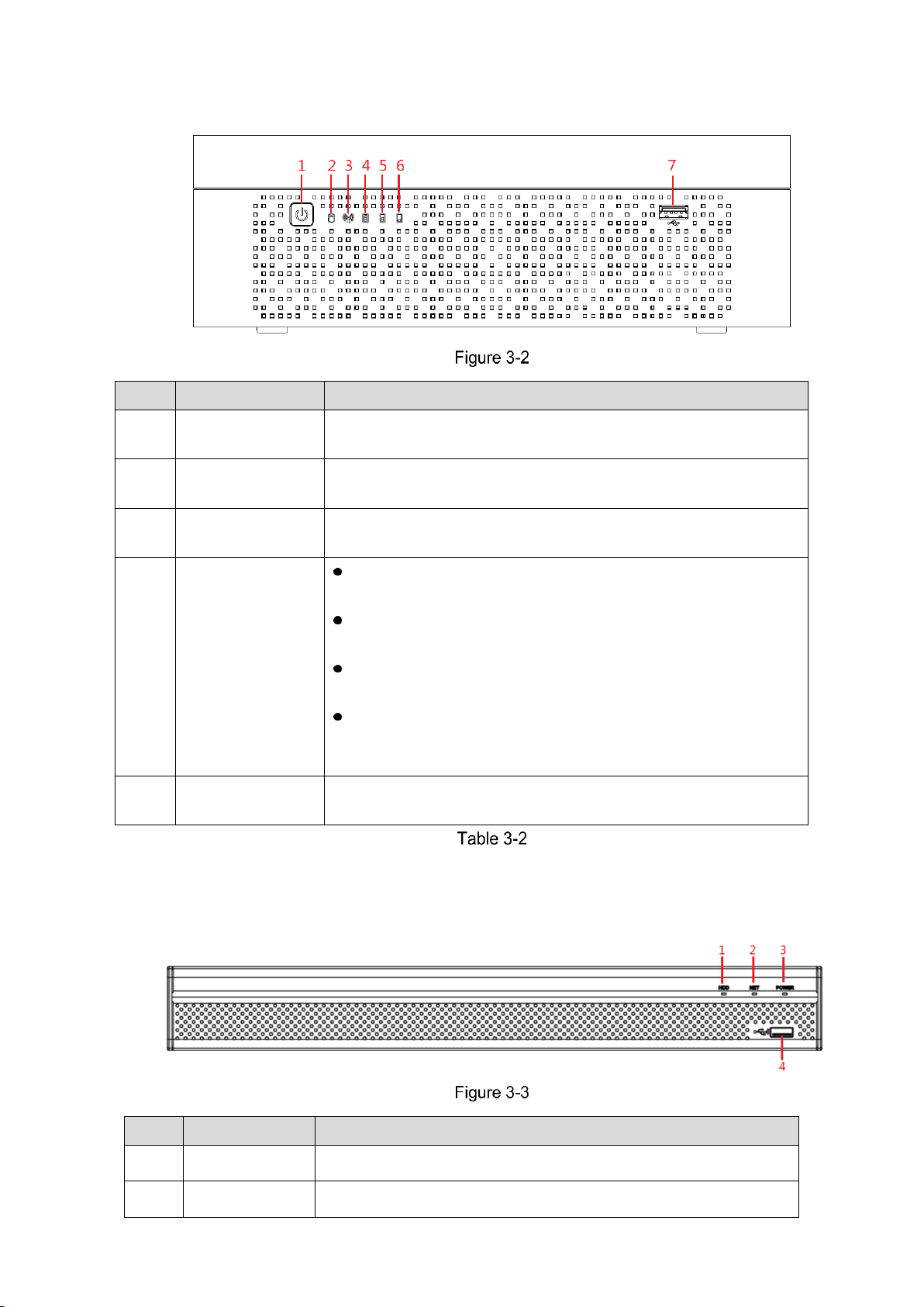
3.1.2 E Model
No.
Button/Icon
Function
1
POWER
Turns on/off the DVR. The indicator glows blue when the DVR is
turned on.
2
HDD status
indicator
The indicator glows blue when the HDD is in malfunction.
3
Network status
indicator
The indicator glows blue when the network connection is
abnormal.
4,5,6
Battery status
indicator
When the battery remains full or no less than sixty percent,
the No.4 indicator is on, and the No.5 and No.6 are out.
When the battery remains between thirty percent and sixty
percent, the No.5 indicator is on and the others are out.
When the battery remains between one percent and thirty
percent, the No.6 indicator is on and the others are out.
When the battery is exhausted, the DVR is turned off, or
there is no battery attached to the DVR, all the three
indicators are out.
7
USB port
Connects to external devices such as USB storage device,
keyboard and mouse.
3.1.3 Compact 1U
No.
Port Name
Function
1
HDD
Glows blue when HDD status is abnormal.
2
NET
Glows blue when network status is abnormal.
Page 20
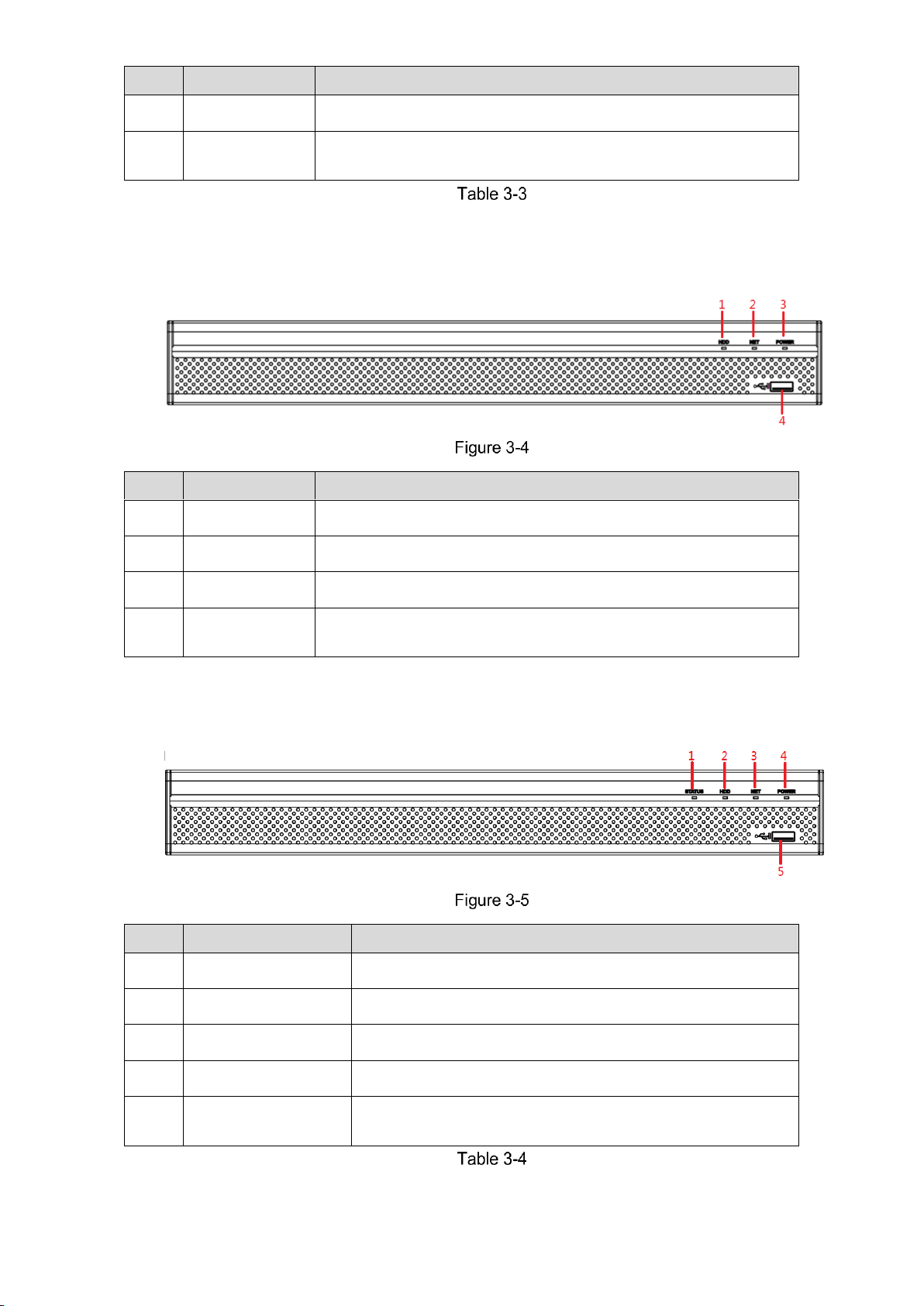
The Grand Tour 10
No.
Port Name
Function
3
POWER
Glows blue when the power is connected properly.
4
USB port
Connects to peripheral devices such as USB storage device,
keyboard and mouse.
3.1.4 MINI 1U
No.
Port Name
Function
1
HDD
Glows blue when HDD status is abnormal.
2
NET
Glows blue when network status is abnormal.
3
POWER
Glows blue when the power is connected properly.
4
USB port
Connects to peripheral devices such as USB storage device,
keyboard and mouse.
3.1.5 1U
No.
Port Name
Function
1
Status indicator light
Glows blue when the device is working properly.
2
HDD
Glows blue when HDD status is abnormal.
3
NET
Glows blue when network status is abnormal.
4
POWER
Glows blue when the power is connected properly.
5
USB port
Connects to the external devices such as keyboard, mouse,
and USB storage device.
Page 21
The Grand Tour 11
3.2 Rear Panel
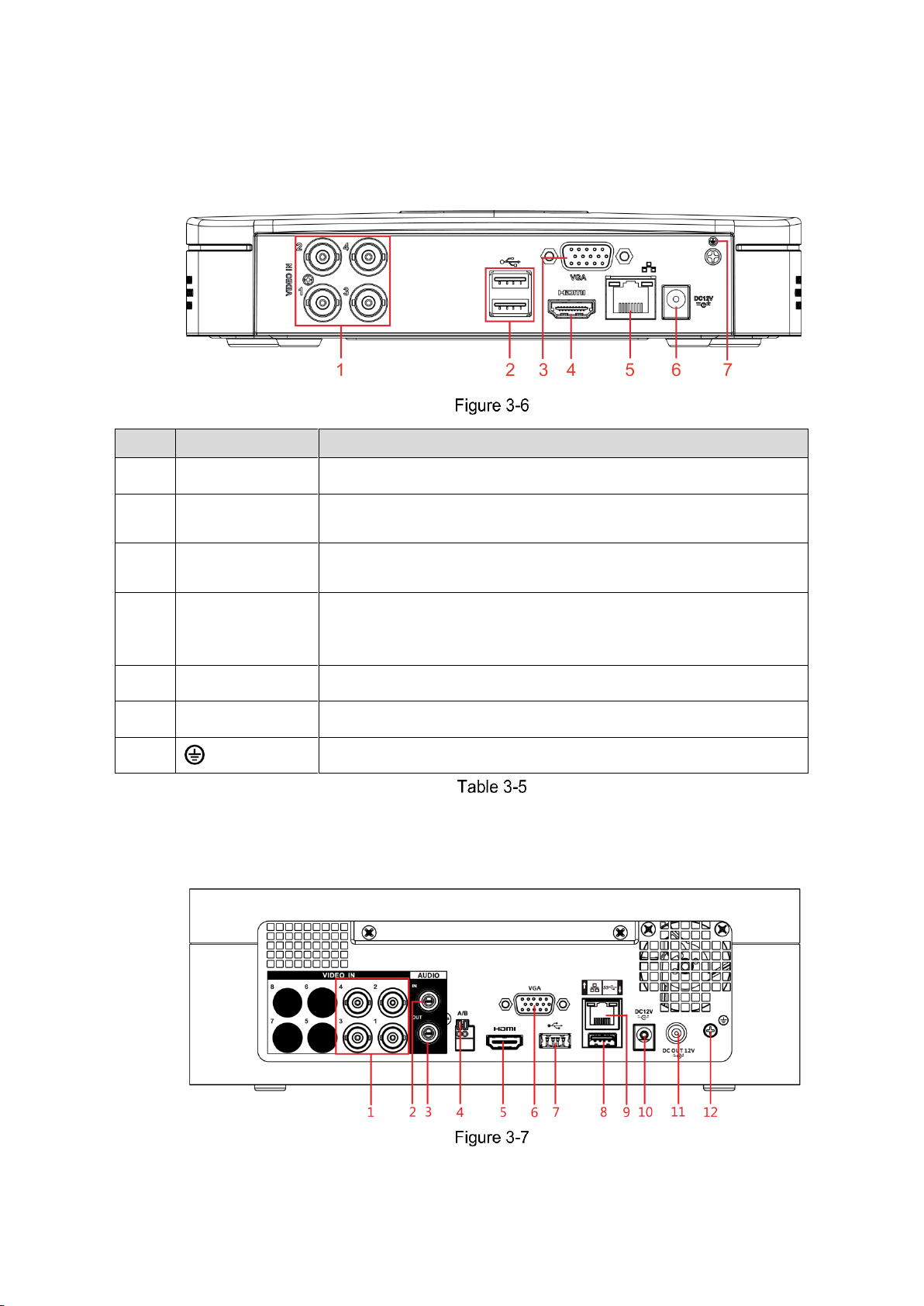
3.2.1 Smart 1U
No.
Port Name
Function
1
Video input port
Connects to analog camera to input video signal.
2
USB port
Connects to external devices such as USB storage device,
keyboard and mouse.
3
VGA port
Outputs analog video data to the connected display with VGA
port.
4
HDMI port
High definition audio and video signal output port.
The port outputs the uncompressed high definition video and
multi-channel audio data to the connected display with HDMI port.
5
Network port
Connects to Ethernet port.
6
Power input port
Inputs DC 12V power.
7 Ground terminal.
3.2.2 E Model
Page 22
The Grand Tour 12
No.
Port Name
Function
1
Video input port
Connects to analog camera to input video signal.
2
Audio input port
Receives audio signal output from the devices such as
microphone.
3
Audio output port
Outputs audio signal to the devices such as the sound box.
4
RS485
communication
port
Connects to the control devices such as speed dome PTZ.
RS485_A port is connected by the cable A and RS485_B is
connected to the cable B.
5
HDMI port
High definition audio and video signal output port.
The port outputs the uncompressed high definition video and
multi-channel audio data to the connected display with HDMI
port.
6
VGA port
Outputs analog video data to the connected display with VGA
port.
7, 8
USB port
Connects to external devices such as USB storage device,
keyboard and mouse.
9
Network port
Connects to Ethernet port.
10
Power input port
Inputs DC 12V power.
11
Power output port
Outputs DC 12V power.
12
Ground
Ground terminal.
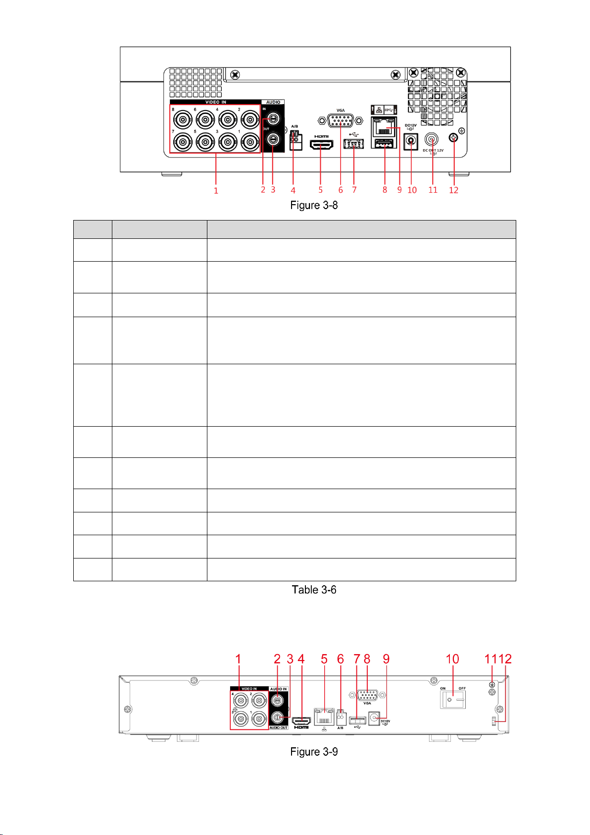
3.2.3 Compact 1U
Page 23
The Grand Tour 13
No.
Port Name
Function
1
Video input port
Connects to analog camera to input video signal.
2
Audio input port
Receives audio signal output from the devices such as
microphone.
3
Audio output port
Outputs audio signal to the devices such as the sound box.
4
HDMI port
High definition audio and video signal output port.
The port outputs the uncompressed high definition video and
multi-channel audio data to the connected display with HDMI port.
5
Network port
Connects to Ethernet port.
6
RS485
communication
port
Connects to the control devices such as speed dome PTZ.
RS485_A port is connected by the cable A and RS485_B is
connected to the cable B.
7
USB port
Connects to external devices such as USB storage device,
keyboard and mouse.
8
VGA port
Outputs analog video data to the connected display with VGA
port.
9
Power input port
Inputs DC 12V power.
10
Power button
Turns on/off the DVR.
11 Ground terminal.
12
Power cable
fastener
Use clamp to secure the power cable on the DVR in case there is
any loss.
3.2.4 MINI 1U
No.
Port Name
Function
Page 24
The Grand Tour 14
No.
Port Name
Function
1
Alarm input port
1–16
4 groups of alarm input ports (Group 1: port 1 to port 4; Group 2:
port 5 to port 8; Group 3: port 9 to port 12; Group 4: port 13 to
port 16). These ports receive the signal from the external alarm
source. There are two types: NO (normal open) and NC (normal
close).
When your alarm input device is using external power, please
make sure the alarm input device and the Device have the same
ground.
Alarm output port
1–3 (NO1–NO3;
C1–C3)
3 groups of alarm output ports (Group 1: port NO1–C1,
Group 2: port NO2–C2, Group 3: port NO3–C3). These ports
output alarm signal to the alarm device. Please make sure
power supply to the external alarm device.
NO: Normal open alarm output port.
C: Alarm output public end.
Ground.
2
Video input port
Connects to analog camera to input video signal.
3
Audio input port
Receives audio signal output from the devices such as
microphone. It corresponds to video input port 1.
4
DB25 port
Connects to the audio splitter taken from the package to convert
to audio input port which receives the audio signal from devices
such as microphone. It corresponds to video input ports 2–16.
5
Audio output port
Outputs audio signal to the devices such as the sound box.
6
HDMI port
High definition audio and video signal output port.
The port outputs the uncompressed high definition video and
multi-channel audio data to the connected display with HDMI
port.
7
USB port
Connects to external devices such as USB storage device,
keyboard and mouse.
8
Network port
Connects to Ethernet port.
9
RS485
communication
port
Connects to the control devices such as speed dome PTZ.
RS485_A port is connected by the cable A and RS485_B is
connected to the cable B.
10
Power input port
Inputs DC 12V power.
11
VGA port
Outputs analog video data to the connected display with VGA
port.
12
Power button
Turns on/off the DVR.
13
Power cable
fastener
Use a cable tie to secure the power cable on the DVR to prevent
loss.
14 Ground terminal.
Page 25

The Grand Tour 15
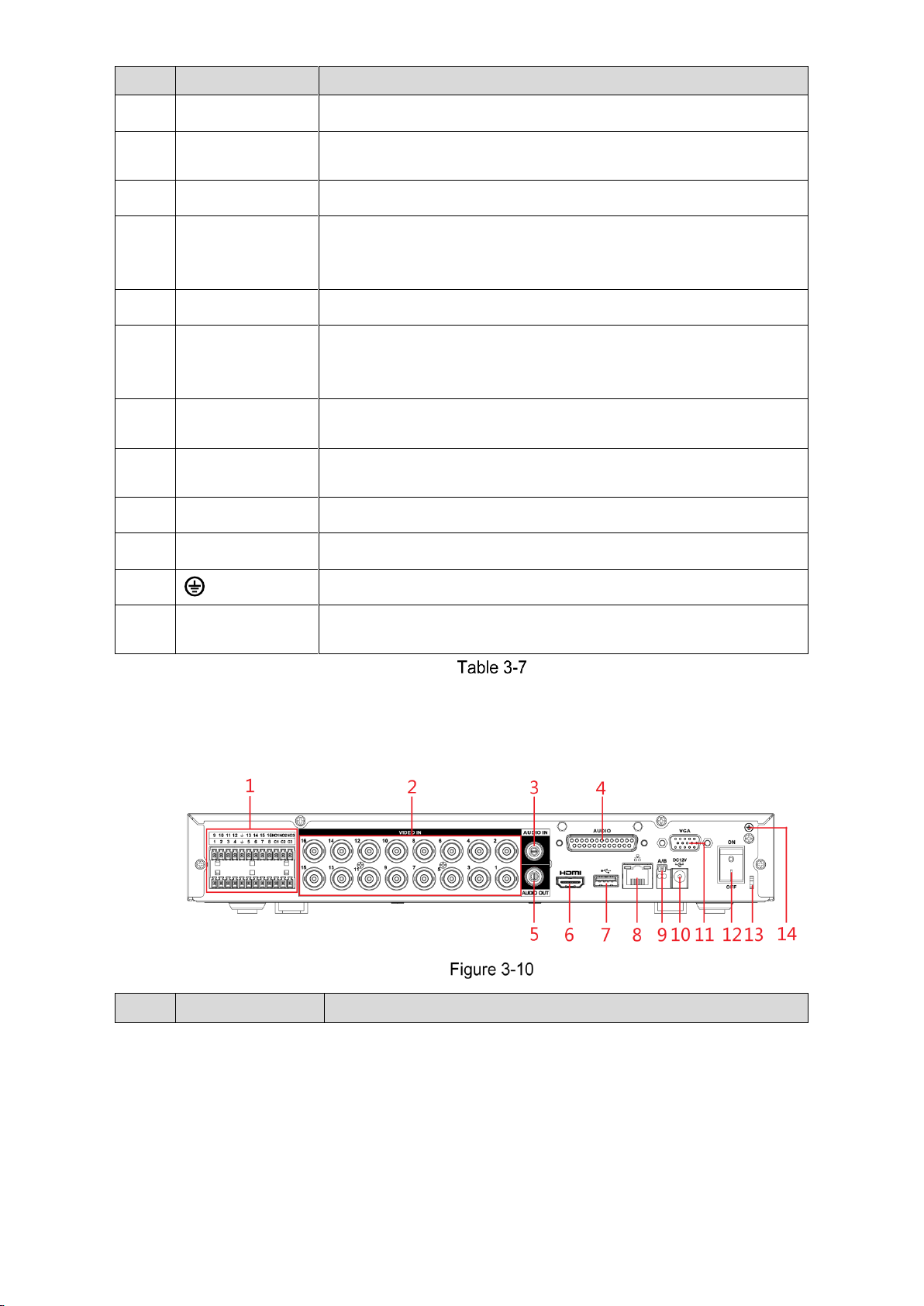
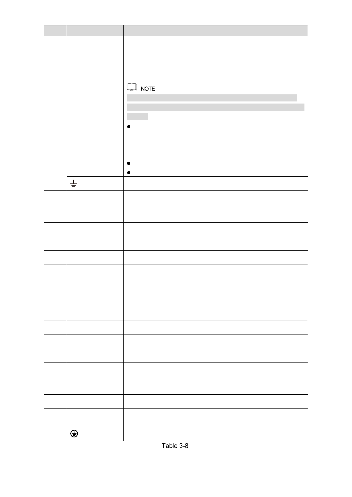
3.2.5 1U
No.
Port Name
Function
1 Ground terminal.
2
Alarm input port
1–16
4 groups of alarm input ports (Group 1: port 1 to port 4; Group 2:
port 5 to port 8; Group 3: port 9 to port 12; Group 4: port 13 to
port 16). These ports receive the signal from the external alarm
source. There are two types: NO (normal open) and NC (normal
close).
When your alarm input device is using external power, please
make sure the alarm input device and the DVR connect to the
same ground.
Alarm output port
1–3 (NO1–NO3;
C1–C3)
3 groups of alarm output ports. (Group 1: port NO1–
C1,Group 2:port NO2–C2,Group 3:port NO3–C3)). These
ports output alarm signal to the alarm device. Please make
sure power supply to the external alarm device.
NO:Normal open alarm output port.
C:Alarm output public end.
Ground.
3
Video input port
Connects to analog camera to input video signal.
4
Audio input port
Receives audio signal output from the devices such as
microphone.
5
Audio output port
Outputs audio signal to the devices such as the sound box.
6
HDMI port
High definition audio and video signal output port.
The port outputs the uncompressed high definition video and
multi-channel audio data to the connected display with HDMI
port.
7
USB port
Connects to the external devices such as keyboard, mouse, and
USB storage device.
8
Network port
Connects to Ethernet port.
9
RS485
communication
port
Connects to the control devices such as speed dome PTZ.
RS485_A port is connected by the cable A and RS485_B is
connected to the cable B.
10
Power input port
Inputs DC 12V power.
Page 26
The Grand Tour 16
No.
Port Name
Function
11
VGA port
Outputs analog video data to the connected display with VGA
port.
12
Power button
Turns on/off the DVR.
13
Power cable
fastener
Use clamp to secure the power cable on the DVR in case there is
any loss.
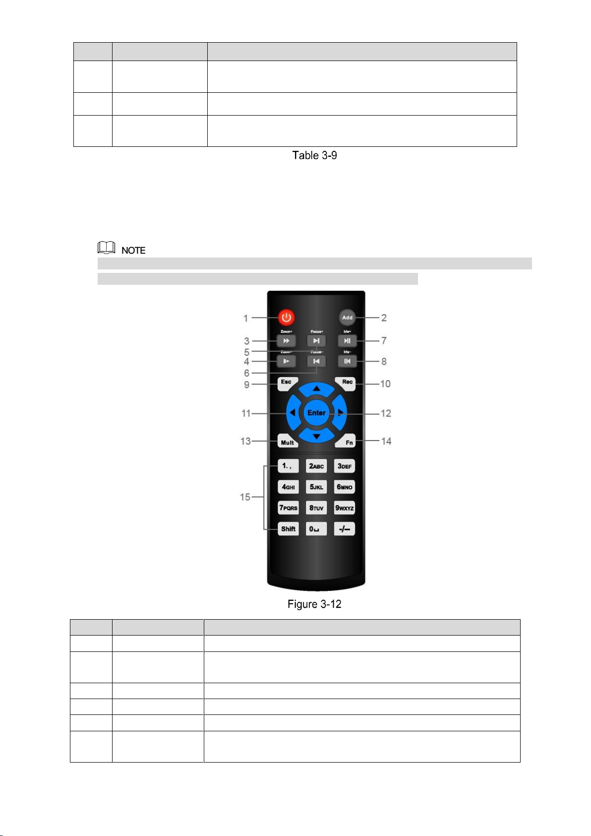
3.3 Remote Control Operations
Please note the remote control is not our standard accessory and might not be included in the
accessary bag. It is supplied dependent on the model you purchased.
No.
Name
Function
1
Power button
Press this button to boot up or shut down the device.
2
Address
Press this button to input device serial number, so that you can
control the Device.
3
Forward
Multi-step forward speed and normal speed playback.
4
Slow motion
Multi-step slow motion speed or normal playback.
5
Next record
In playback state, press this button to play back the next video.
6
Previous record
In playback state, press this button to play back the previous
video.
Page 27
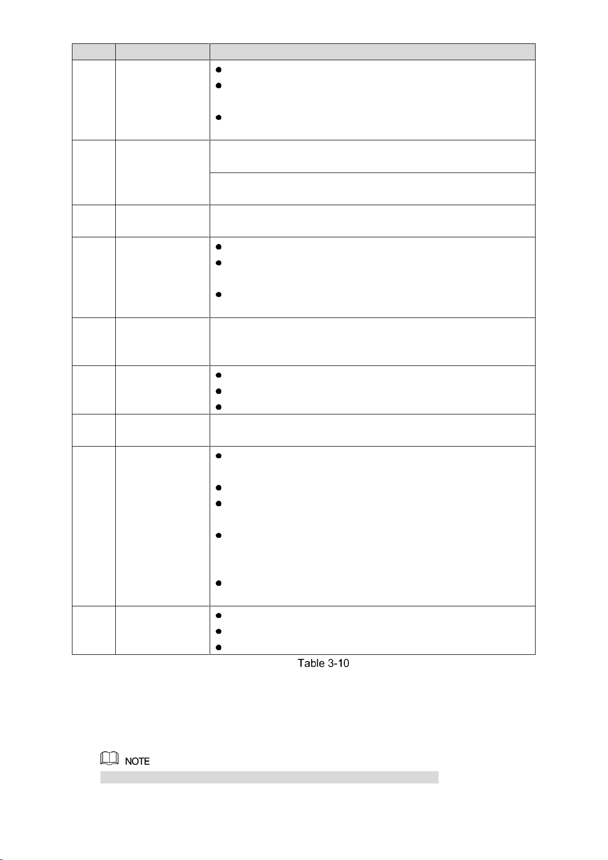
The Grand Tour 17
No.
Name
Function
7
Play/Pause
In normal playback state, press this button to pause playback.
In pause state, press this button to resume to normal
playback.
In live view window interface, press this button to enter video
search menu.
8
Reverse/pause
In the reverse playback state, press this button to pause reverse
playback.
In the reverse playback pause state, press this button to resume to
playback reversing state.
9
Esc.
Go back to previous menu or cancel current operation (close front
interface or control).
10
Record
Start or stop record manually.
In record interface, use the direction buttons to select the
channel that you want to record.
Press this button for at least 1.5 seconds, and the manual
record interface will be displayed.
11
Direction keys
Switch between current activated controls by going left or right.
In playback state, the keys control the playback progress bar.
Aux function (such as operating the PTZ menu).
12
Enter/menu key
Confirms an operation.
Go to the OK button.
Go to the menu.
13
Multiple-window
switch
Switch between multiple-window and one-window.
14
Fn
In single-channel monitoring mode, press this button to
display the PTZ control and color setting functions.
Switch the PTZ control menu in PTZ control interface.
In motion detection interface, press this button with direction
keys to complete setup.
In text mode, press and hold this button to delete the last
character. To use the clearing function: Long press this button
for 1.5 seconds.
In HDD menu, switch HDD recording time and other
information (as indicated in the pop-up message.
15
Alphanumeric
keys
Input password, numbers.
Switch channel.
Press Shift to switch the input method.
3.4 Mouse Operations
The operations are based on the considerations for right-handed users.
Page 28

The Grand Tour 18
Operation
Function
Click left mouse
button
Password input dialogue box pops up if you have not logged in yet.
In live view window interface, you can go to the main menu.
When you have selected one menu item, click it to view menu content.
Implement the control operation.
Modify checkbox or motion detection status.
Click combo box to pop up drop-down list.
In text box, click the corresponding button on the panel to enter a numeral
or English character (small/capitalized).
In English input mode: Click to enter a backspace and click
to delete the previous character.
In numeral input mode: Click to clear and click to delete the
previous character.
Double-click left
mouse button
Implement special control operations such as double-click one item in the
file list to play back the video.
In multiple-window mode, double-click one channel to view in full-window.
Double-click current video again to go back to previous multiple-window
mode.
Right-click
Right-click in live view window interface, the shortcut menu is displayed. For
different series product, the shortcut menu may vary.
Exit current menu without saving the modification.
Click scroll wheel
button
In numeral input box: Increase or decrease numeral value.
Switch the items in the check box.
Page up or page down.
Point to select
and move
Select current control and move it.
Dragging a
selection box
with left mouse
button
Select motion detection zone.
Select privacy mask zone.
Page 29
Connecting Basics 19
4 Connecting Basics
This chapter introduces various components of the Device, remote control and mouse
operations, and typical connection.
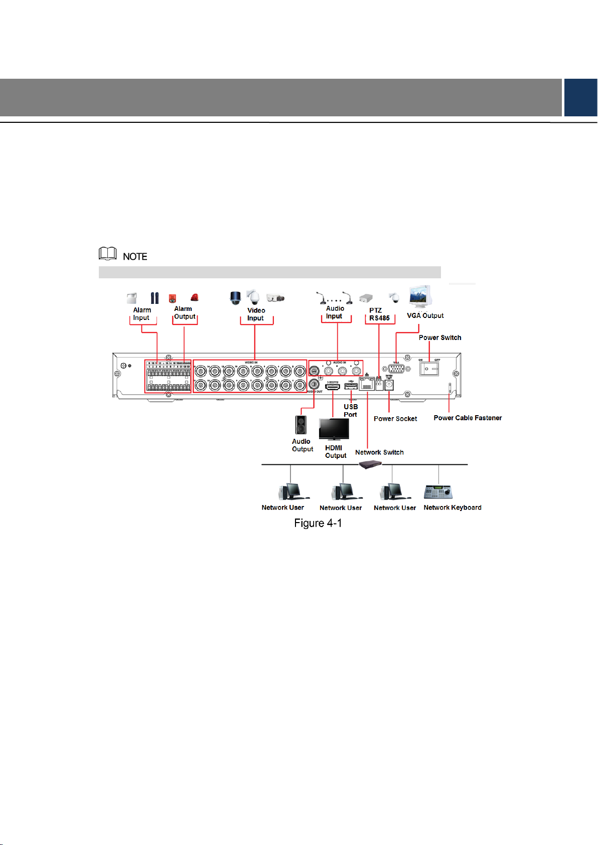
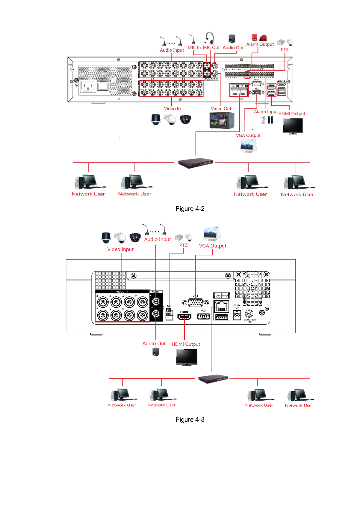
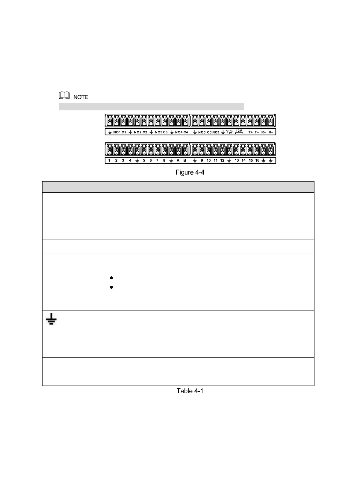
4.1 Typical Connection Diagram
The following figure is for reference only. The actual product shall govern.
Page 30
Connecting Basics 20
Page 31

Connecting Basics 21
4.2 Connecting to Video and Audio Input and Output
4.2.1 Video Input
The video input interface is BNC. The input video format includes: PAL/NTSC BNC (1.0V
P-P
,
75Ω.).
The video signal should comply with your national standards.
The input video signal shall have high SNR, low distortion; low interference, natural color and
suitable lightness.
Guarantee the stability and reliability of the camera signal
The camera shall be installed in a cool, dry place away from direct sunlight, inflammable,
explosive substances and etc.
The camera and the DVR should have the same grounding to ensure the normal operation of
the camera.
Guarantee stability and reliability of the transmission line
Please use high quality, sound shielded BNC. Please select suitable BNC model according to
the transmission distance.
If the distance is too long, you should use twisted pair cable, and you can add video
compensation devices or use optical fiber to ensure video quality.
You should keep the video signal away from the strong electromagnetic interference, especially
the high tension current.
Keep connection lugs in well contact
The signal line and shielded wire should be fixed firmly and in well connection. Avoid dry joint,
lap welding and oxidation.
4.2.2 Video Output
Video output includes a BNC (PAL/NTSC1.0V
P-P
, 75Ω) output, a VGA output and HDMI output.
System supports BNC, VGA and HDMI output at the same time.
When you are using pc-type monitor to replace the monitor, please pay attention to the
following points:
To defer aging, do not allow the pc monitor to run for a long time.
Regular demagnetization will keep device maintain proper status.
Keep it away from strong electromagnetic interference devices.
Using TV as video output device is not a reliable substitution method. You also need to reduce
the working hour and control the interference from power supply and other devices. The low
quality TV may result in device damage.
Page 32

Connecting Basics 22
4.2.3 Audio Input
These series products audio input port adopt BNC port.
Due to high impedance of audio input, please use active sound pick-up.
Audio transmission is similar to video transmission. Try to avoid interference, dry joint, loose
contact and it shall be away from high tension current.
4.2.4 Audio Output
The audio output signal parameter is usually over 200mv 1KΩ (BNC or RCA). It can directly
connect to low impedance earphone, active sound box or amplifier-drive audio output device.
If the sound box and the pick-up cannot be separated spatially, it is easy to arouse squeaking.
In this case you can adopt the following measures:
Use better sound pick-up with better directing property.
Reduce the volume of the sound box.
Using more sound-absorbing materials in decoration can reduce voice echo and improve
acoustics environment.
Adjust the layout to reduce happening of the squeaking.
4.3 Connecting to Alarm Input and Output
Please read the followings before connecting.
Alarm input
Please make sure alarm input mode is grounding alarm input.
Grounding signal is needed for alarm input.
Alarm input needs the low level voltage signal.
Alarm input mode can be either NC (normal Open) or NO (Normal Close)
When you are connecting two DVRs or you are connecting one DVR and one other device,
please use a relay to separate them.
Alarm output
The alarm output port should not be connected to high power load directly (It shall be less than
1A) to avoid high current which may result in relay damage. Please use the contactor to realize
the connection between the alarm output port and the load.
How to connect PTZ decoder
Ensure the decoder has the same grounding with DVR, otherwise you may not control the
PTZ. Shielded twisted wire is recommended and the shielded layer is used to connect to
the grounding.
Avoid high voltage. Ensure proper wiring and some thunder protection measures.
For too long signal wires, 120Ω should be parallel connected between A, B lines on the far
end to reduce reflection and guarantee the signal quality.
“485 A, B” of DVR cannot parallel connect with “485 port” of other device.
The voltage between of A, B lines of the decoder should be less than 5V.
Page 33
Connecting Basics 23
Please make sure the front-end device has soundly earthed
Improper grounding may result in chip damage.
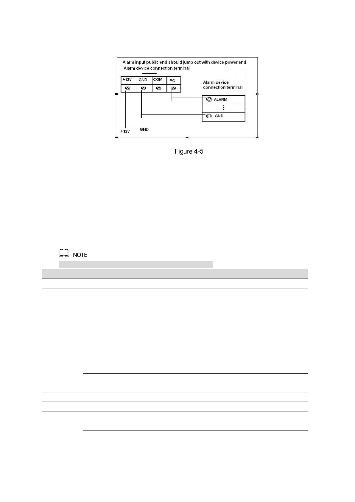
4.3.1 Introducing Alarm Port
The alarm input ports are dependent on the model you purchased.
Icon
Description
1,2,3,4,5,6,
7,8,9,10,11 ,
12,13,14,15,16
ALARM 1 to ALARM 16. The alarm becomes active in low voltage.
NO1 C1, NO2 C2,
NO3 C3, NO4 C4
There are four groups of normal open activation output (on/off button).
NO5 C5 NC5,
There is one group of normal open activation output (on/off button).
CTRL 12V
Control power output of the 6th alarm output channel. Voltage current:
500mA.
When there is an alarm output, close the power output.
When the alarm is cancelled, open the power output.
+12V
Rated current.
Voltage current: 500mA.
Ground cable.
485 A/B
485 communication port. They are used to control devices such as
decoder. 120Ω should be parallel connected between A, B lines if there
are too many PTZ decoders.
T+,T-,R+,R-
Four-wire full-duplex RS485 port.
T+ T-: output wire.
R+ R-: input wire.
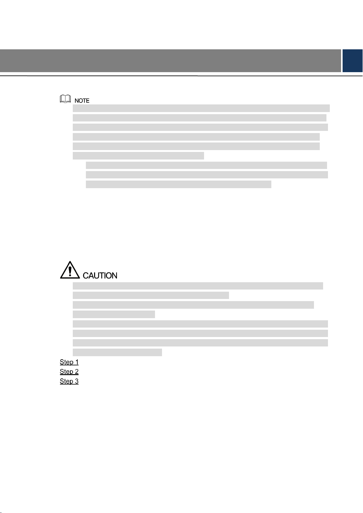
4.3.2 Alarm Input
Please refer to the following figure for more information.
Grounding alarm inputs which includes Normal open and Normal close type.
Please parallel connect COM end and GND end of the alarm detector (Provide external
power to the alarm detector).
Page 34
Connecting Basics 24
Please parallel connect the Ground of the DVR and the ground of the alarm detector.
Please connect the NC port of the alarm sensor to the DVR alarm input(ALARM)
Use the same ground with that of DVR if you use external power to the alarm device.
4.3.3 Alarm Output
Provide external power to external alarm device.
To avoid overloading, please read the following relay parameters table carefully.
RS485 A/B cable is for the A/B cable of the PTZ decoder.
4.3.4 Alarm Output Relay Parameters
Refer to the actual product for relay model information.
Model
HFD23/005-1ZS
HRB1-S-DC5V
Material of the touch
AgNi+ gold-plating
AuAg10/AgNi10/CuNi30
Rating
(Resistance
Load)
Rated switch
capacity
30V DC 1A/125V AC 0.5A
24V DC 1A/125V AC 2A
Maximum switch
power
62.5VA/30W
250VA/48W
Maximum switch
voltage
125V AC/60V DC
125V AC/60V DC
Maximum switch
currency
2A
2A
Insulation
Between touches
400VAC 1 minute
500VAC 1 minute
Between touch and
winding
1000VAC 1 minute
1000VAC 1 minute
Turn-on Time
5ms max
5ms max
Turn-off Time
5ms max
5ms max
Longevity
Mechanical
1×10
7
times
(300 times/MIN)
5×10
6
times
(300 times/MIN)
Electrical
1×10
5
times
(30 times/MIN)
2.5×10
4
times
(30 times/MIN)
Working Temperature
-30℃–+70℃
-40℃–+70℃
Page 35

Connecting Basics 25
4.4 Connecting to RS485 Port
Connect the RS485 cable of the PTZ camera to the RS485 port on the Device. Ensure
the match of A and B interfaces.
Connect the video out cable of the PTZ camera to the video input port on the Device.
Turn on the PTZ camera.
4.5 Replacing Battery
Please make sure to use the same battery model if possible.
We recommend replace battery regularly (such as one-year) to guarantee system time
accuracy.
Before replacement, please save the system setup, otherwise, you may lose the data
completely!
Page 36
Local Configurations 26
5 Local Configurations
Please read the following notes prior to using your Device.
The interfaces in the Manual are used for introducing the operations and only for reference.
The actual interface might be different dependent on the model you purchased. If there is
inconsistency between the Manual and the actual product, the actual product shall govern.
The Manual is a general document for introducing the product, so there might be some
functions described for the Device in the Manual not apply to the model you purchased.
Conventions for mouse operations on a menu.
Click: On the menu, left-click the mouse once on an option to enter the option setting.
Right-click: On any interface, right-click the mouse once to return to the previous level.
For details about mouse operations, see "3.4 Mouse Operations."
5.1 Initial Settings
5.1.1 Booting up
Ensure the input voltage corresponds to the power requirement of the Device. Power on
the Device after the power cable is properly connected.
To protect the Device, please connect the Device with the power cable first, and then
connect to the power source.
To ensure the stable work of the Device and the external devices connected to the Device
and to prolong the batter life, it is recommended to refer to the national related standard to
use the power source that provides stable voltage with less interference from ripples. USP
power source is recommended.
Connect the Device to the monitor.
Plug in the power cable to the Device.
Press the power button to turn on the Device. The power indicator light is on.
On the connected monitor, the live view screen is displayed by default. If you turn on
the Device during the time period that is configured for recording, the system starts
recording after it is turned on, and you will see the icon indicating recording status is
working in the specific channels.
5.1.2 Initializing the Device
When booting up for the first time, you need to configure the password information for admin
(by default).
Page 37

Local Configurations 27
To secure the Device, it is strongly recommended for you to properly keep the password for
admin and modify it regularly.
Turn on the Device.
The Device Initialization interface is displayed. See Figure 5-1.
Configure the password information for admin. For details, see Table 5-1.
Parameter
Description
User
By default, the user is admin.
Password
In the Password box, enter the password for admin.
The new password can be set from 8 characters through 32
characters and contain at least two types from number, letter and
special characters (excluding"'", """, ";", ":" and "&").
Confirm Password
Prompt Question
In the Prompt Question box, enter the information that can remind
you of the password.
On the login interface, click , the prompt will display to help you
find back the password.
Click Next.
The unlock pattern setting interface is displayed. See Figure 5-2.
Page 38

Local Configurations 28
Draw a unlock pattern.
After the setting is completed, the password protection settings interface is displayed.
See Figure 5-3.
The pattern that you want to set must cross at least four points.
If you do not want to configure the unlock pattern, click Skip.
Once you have configured the unlock pattern, the system will require the unlock
pattern as the default login method. If you skip this setting, enter the password for
login.
Page 39

Local Configurations 29
Configure the protection parameters for password. For details, see Table 5-2.
After configuration, if you forgot the password for admin user, you can reset the
password through the reserved email address or security questions. For details about
resetting the password, see "5.1.3 Resetting Password."
If you do not want to configure the settings, disable the email address and security
questions functions on the interface.
Password
Protection Mode
Description
Email Address
Enter the reserved email address.
In the Email Address box, enter an email address for password
reset. In case you forgot password, enter the security code that you
will get from this reserved email address to reset the password of
admin.
Security
Questions
Configure the security questions and answers.
In case you forgot password, enter the answers to the questions can
make you reset the password.
If you want to configure the email or security questions fucntion later or you want to
change the configurations, select Main Menu > ACCOUNT > USER.
Click Save to complete the settings.
The End-User License Agreement interface is displayed.
Select the I have read and agree to all terms check box.
Click Next.
The Startup Wizard interface is displayed. For details about quick settings during
startup, see "5.1.4 Setting Up with the Startup Wizard."
5.1.3 Resetting Password
You can reset the password through the QR code or the security questions.
To reset through the QR code, make sure the Enable check box is selected in Main Menu >
SYSTEM > SECURITY > Password Reset.
To reset through the security questions, make sure the security quesitons is configured.
Enter the login interface.
If you have configured unlock pattern, the unlock pattern login interface is
displayed. See Figure 5-4. Click Forgot Pattern, the password login interface is
displayed. See Figure 5-5.
If you did not configure unlock pattern, the password login interface is displayed.
See Figure 5-5.
On the unlock pattern login interface, click Switch User to login; or on the password
login interface, in the User Name list, select other users to login.
Page 40

Local Configurations 30
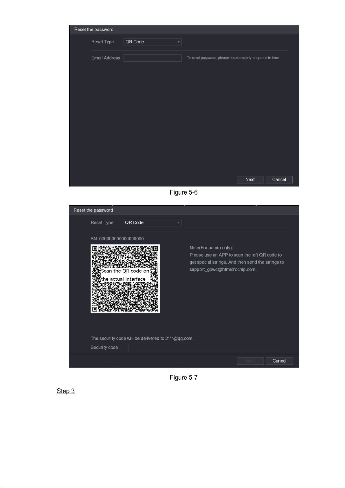
Click .
If you did not set the reserved email address, the email entering interface is
displayed. See Figure 5-6. Enter the email address, and then click Next, the Reset
the password interface is displayed. See Figure 5-7.
If you have set the reserved email address, the Reset the password interface is
displayed. See Figure 5-7.
Page 41
Local Configurations 31
Rest the password.
QR code
Follow the onscreen instructions to get the security code in your reserved email
address. In the Security code box, enter the security code.
Page 42

Local Configurations 32
You are given the limited times to get the security code by scanning the QR
code within 24 hours. Please operate carefully.
Please use the security code received in your email box to reset the password
within 24 hours; otherwise the security code becomes invalid.
Security questions
On the Reset the password interface as shown in Figure 5-6, in the Reset Type
list, select Security Questions, the Security Questions interface is displayed, see
Figure 5-8.
If you did not configure the security questions before, in the Reset Type list, there
will be no Security Questions.
In the Answer box, enter the correct answers.
Click Next.
The new password resetting interface is displayed. See Figure 5-9.
Page 43

Local Configurations 33
In the New Password box, enter the new password and enter it again in the Confirm
Password box.
Click Save. The password resetting is started.
After resetting is completed, a pop-up message is displayed.
Click OK.
A pop-up message is displayed asking if you want to sync the password with the
remote devices, see Figure 5-10.
Click Cancel, the resetting is finished.
Click OK, the Sync Info interface is displayed. See Figure 5-10.
Page 44
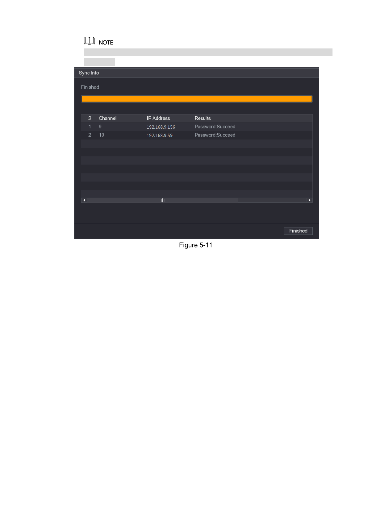
Local Configurations 34
This message appears only when there are digital channels instead of complete analog
channels.
5.1.4 Setting Up with the Startup Wizard
5.1.4.1 Entering Startup Wizard
The Startup Wizard helps you configure the basic settings to set up the Device.
After you have initialized the Device, the Startup Wizard interface is displayed. See Figure
5-12.
Page 45

Local Configurations 35
If you select the Auto-check for updates check box, the system will notify you automatically
when updates are available.
5.1.4.2 Configuring General Settings
You can configure the general settings for the Device such as Device name, language, and
settings for instant playback.
You can also configure general settings by selecting Main Menu > SYSTEM > GENERAL >
General.
On the Startup Wizard interface, click Next.
The General interface is displayed. See Figure 5-13.
Page 46

Local Configurations 36
Configure the general settings parameters. See Table 5-3.
Parameter
Description
Device Name
In the Device Name box, enter the Device name.
Device No.
In the Device No. box, enter a number for the Device.
Language
In the Language list, select a language for the Device system.
Video Standard
In the Video Standard list, select PAL or NTSC according to your actual
situation.
Instant Play (Min.)
In the Instant Play box, enter the time length for playing back the
recoded video. The value ranges from 5 to 60.
On the live view control bar, click the instant playback button to play back
the recorded video within the configured time.
Auto Logout (Min.)
In the Auto Logout box, enter the standby time for the Device. The
Device automatically logs out when it is not working for the configured
time period. You need to login the Device again.
The value ranges from 0 to 60. 0 indicates there is not standby time for
the Device.
Click Monitor Channel(s) when logout. You can select the channels
that you want to continue monitoring when you logged out.
Navigation Bar
Enable the navigation bar. When you click on the live view screen, the
navigation bar is displayed.
Mouse Sensitivity
Adjust the speed of double-click by moving the slider.
The bigger the value is, the faster the double-clicking speed must be.
Page 47

Local Configurations 37
5.1.4.3 Configuring Date and Time Settings
You can configure the system time, choose the time zone, set the daylight saving time, and
enable the NTP server.
You can also configure date and time settings by selecting Main Menu > SYSTEM >
GENERAL > Date&Time.
After you have configured the general settings, on the General interface, click Next.
The Date&Time interface is displayed. See Figure 5-14.
Configure the settings for date and time parameters. See Table 5-4.
Parameter
Description
System Time
In the System Time box, enter time for the system.
Click the time zone list, you can select a time zone for the system, and
the time in adjust automatically.
Do not change the system time randomly; otherwise the recorded video
cannot be searched. It is recommended to avoid the recoding period or
stop recording first before you change the system time.
Date Format
In the Date Format list, select a date format for the system.
Date Separator
In the Date Separator list, select a separator style for the date.
Time Format
In the Time Format list, select 12-HOUR or 24-HOUR for the time
display style.
DST
Enable the Daylight Saving Time function. Click Week or click Date.
Start Time
Configure the start time and end time for the DST.
End Time
Page 48

Local Configurations 38
Parameter
Description
NTP
Enable the NTP function to sync the Device time with the NTP server.
Server
In the Server box, enter the IP address or domain name of the
corresponding NTP server.
Click Manual Update, the Device starts syncing with the server
immediately.
Port
The system supports TCP protocol only and the default setting is 123.
Interval (Min.)
In the Interval box, enter the amount of time that you want the Device to
sync time with the NTP server. The value ranges from 0 to 65535.
5.1.4.4 Configuring Network Settings
You can configure the basic network settings such as net mode, IP version, and IP address of
the Device.
You can also configure network settings by selecting Main Menu > NETWORK > TCP/IP.
After you have configured the date and time settings, on the Date&Time interface, click
Next.
The NETWORK interface is displayed. See Figure 5-15.
Configure the settings for network parameters. See 0.
Parameter
Description
Net Mode
Multi-address: Two Ethernet ports work separately through either
of which you can request the Device to provide the services such
as HTTP and RTSP. You need to configure a default Ethernet port
(usually the Ethernet port 1 by default) to request the services from
the device end such as DHCP, Email and FTP. If one of the two
Page 49
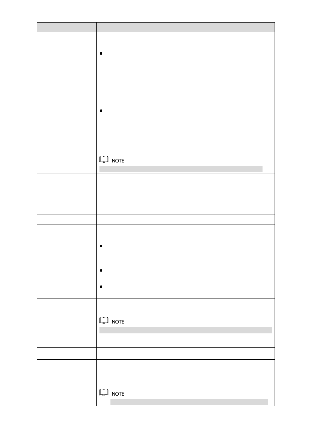
Local Configurations 39
Parameter
Description
Ethernet ports is disconnected as detected by networking testing,
the system network status is regarded as offline.
Fault Tolerance: Two Ethernet ports share one IP address.
Normally only one Ethernet port is working and when this port fails,
the other port will start working automatically to ensure the network
connection.
When testing the network status, the network is regarded as offline
only when both of the two Ethernet ports are disconnected. The
two Ethernet ports are used under the same LAN.
Load Balance: Two network cards share one IP address and they
are working at the same time to share the network load averagely.
If one of them fails, the other can continue working normally.
When testing the network status, the network is regarded as offline
only when both of the two Ethernet ports are disconnected. The
two Ethernet ports are used under the same LAN.
The Device with single Ethernet port does not support this function.
Default Ethernet Port
In the Ethernet Card list, select an Ethernet port as a default port.
This setting is available only when the Multi-address is selected in the
Net Mode list.
IP Version
In the IP Version list, you can select IPv4 or IPv6. Both versions are
supported for access.
MAC Address
Displays the MAC address of the Device.
DHCP
Enable the DHCP function. The IP address, subnet mask and default
gateway are not available for configuration once DHCP is enabled.
If DHCP is effective, the obtained information will display in the IP
Address box, Subnet Mask box and Default Gateway box. If not,
all values show 0.0.0.0.
If you want manually configure the IP information, disable the
DHCP function first.
If PPPoE connection is successful, the IP address, subnet mask,
default gateway, and DHCP are not available for configuration.
IP Address
Enter the IP address and configure the corresponding subnet mask and
default gateway.
IP address and default gateway must be in the same network segment.
Subnet Mask
Default Gateway
DNS DHCP
Enable the DHCP function to get the DNS address from router.
Preferred DNS
In the Preferred DNS box, enter the IP address of DNS.
Alternate DNS
In the Alternate DNS box, enter the IP address of alternate DNS.
MTU
In the MTU box, enter a value for network card. The value ranges from
1280 byte through 1500 byte. The default is 1500.
Modifying MTU value will cause network interruption and restart,
Page 50
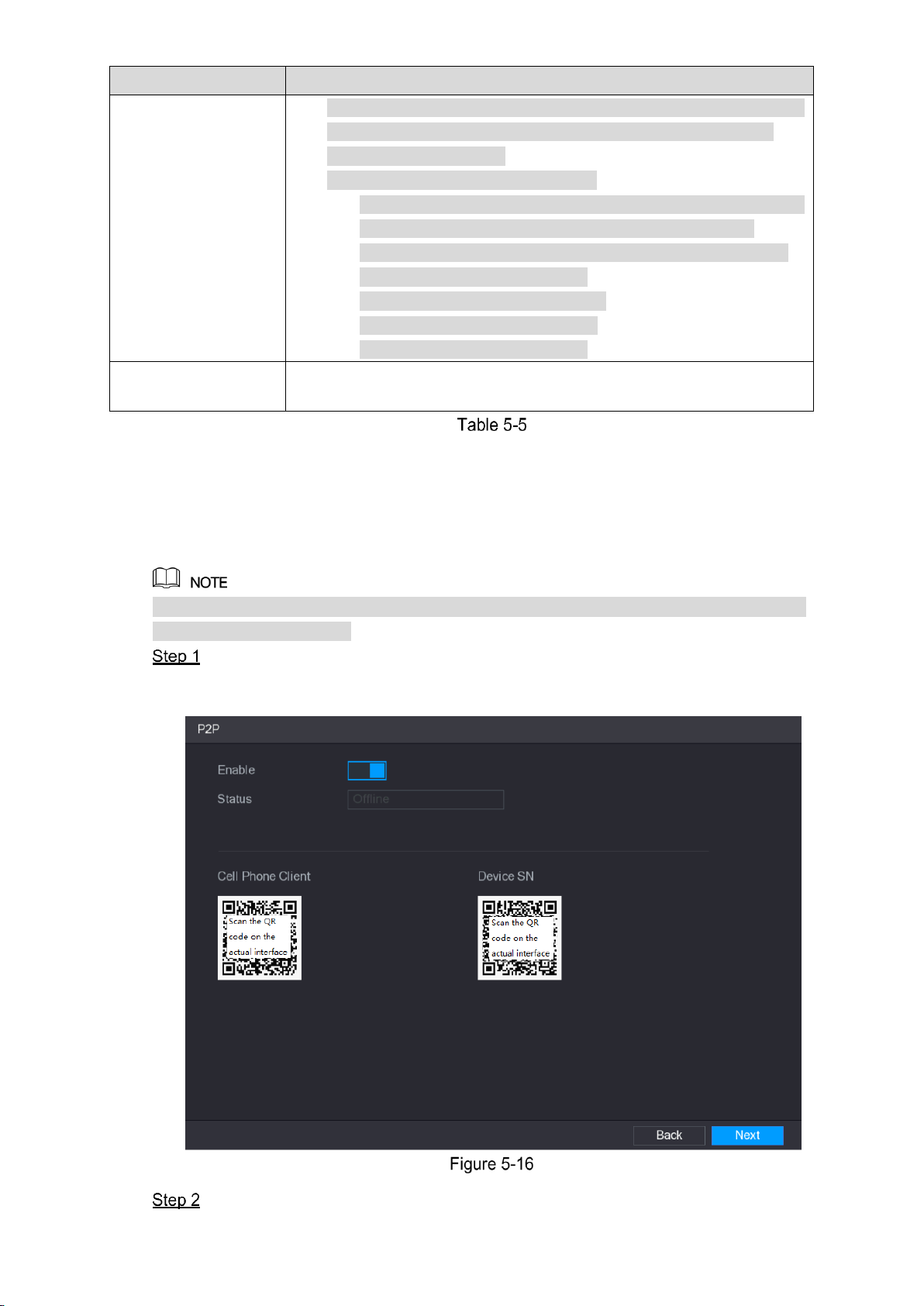
Local Configurations 40
Parameter
Description
which interrupt the network service. There is a pop-up message to
let you confirm if you want to save the modification, if yes, the
modification takes effect.
Suggested MTU values are as below.
1500: The biggest value of Ethernet information package. This
value is typically selected if there is no PPPoE or VPN
connection, and it is also the default value of some routers,
network adapters and switches.
1492: Optimized value for PPPoE.
1468: Optimized value for DHCP.
1450: Optimized value for VPN.
Test
Click Test to test if the entered IP address and gateway are
interworking.
5.1.4.5 Configuring P2P Settings
You can add the Device into your cell phone client or the platform to manage.
You can also configure P2P function by selecting Main Menu > NETWORK > P2P.
Make sure the DVR is connected into the Internet, and if yes, in the Status box of the P2P
interface, it shows Online.
After you have configured the network settings, on the NETWORK interface, click
Next.
The P2P interface is displayed. See Figure 5-16.
Enable the P2P function.
Page 51
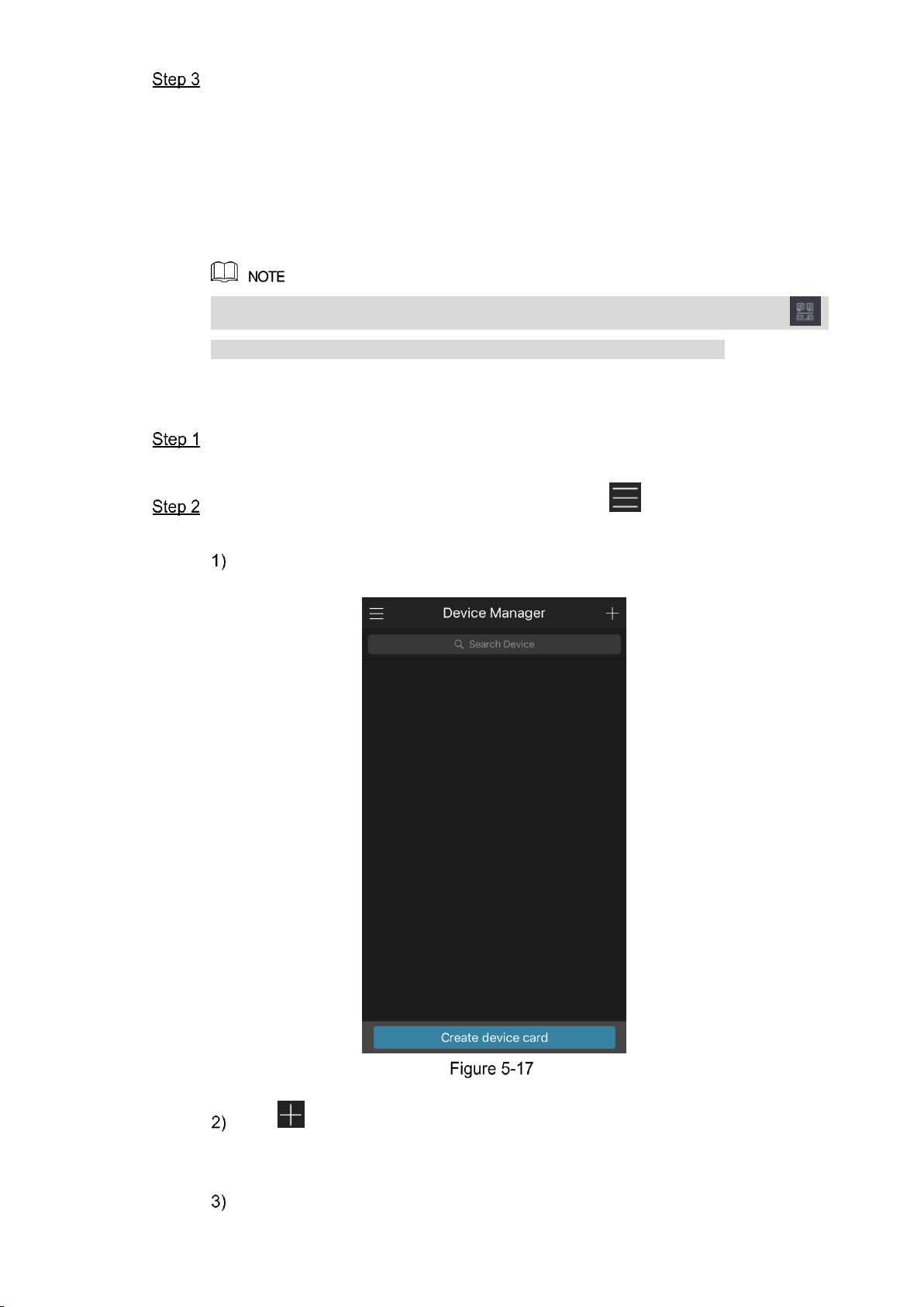
Local Configurations 41
Click Apply.
You can start adding the device.
Cell Phone Client: Use your mobile phone to scan the QR code to add the device
into the Cell Phone Client, and then you can start accessing the Device.
Platform: Obtain the Device SN by scanning the QR code. Go to the P2P
management platform and add the Device SN into the platform. Then you can
access and manage the device in the WAN. For details, please refer to the P2P
operation manual.
You can also enter the QR code of Cell Phone Client and Device SN by clicking
on the top right of the interfaces after you have entered the Main Menu.
To use this function, take adding device into Cell Phone Client as an example.
Adding Device into Cell Phone Client
Use your cell phone to scan the QR code under Cell Phone Client to download the
application.
On your cell phone, open the application, and then tap .
The menu is displayed. You can start adding the device.
Tap Device Manager.
The Device Manager interface is displayed. See Figure 5-17.
Tap on the top right corner.
The interface requiring device initialization is displayed. A pop-up message
reminding you to make sure the Device is initialized is displayed.
Tap OK.
Page 52
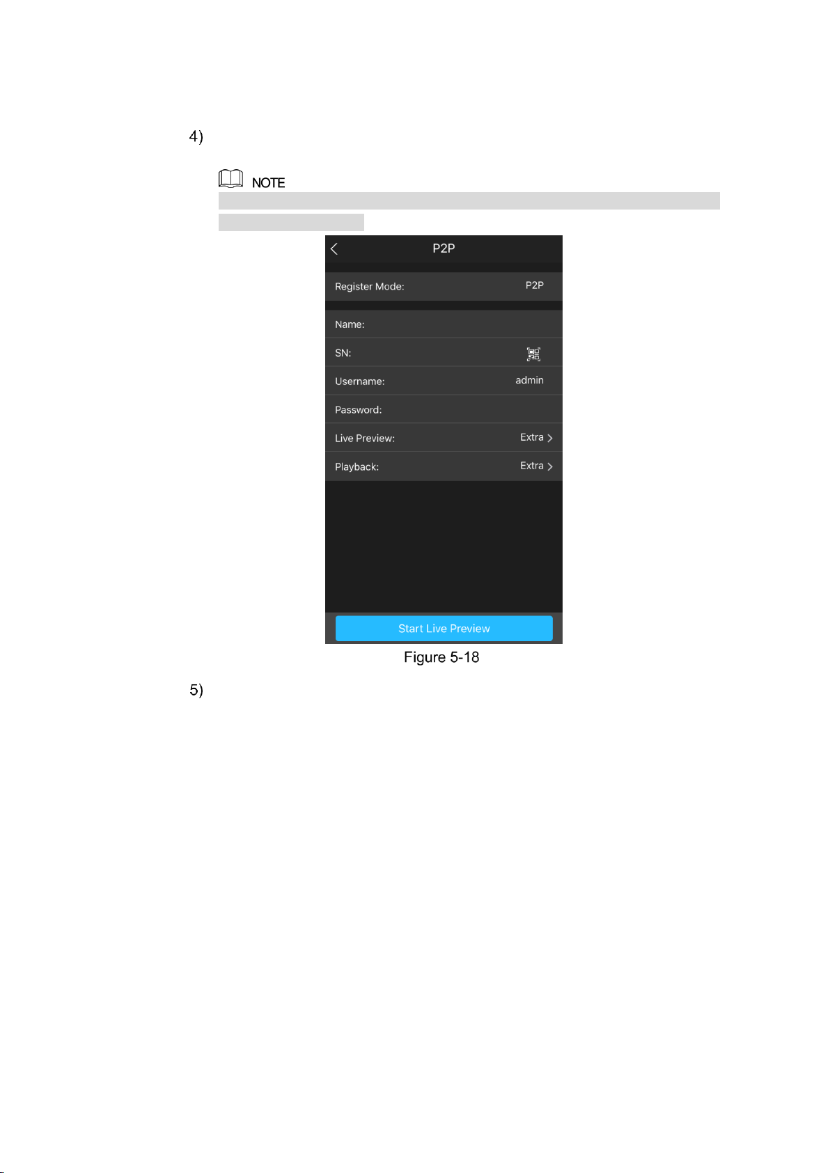
Local Configurations 42
If the Device has not been initialized, Tap Device Initialization to perform
initializing by following the onscreen instructions.
If the Device has been initialized, you can start adding it directly.
Tap Add Device.
The Add Device interface is displayed. See Figure 5-18.
You can add wireless device or wired device. The Manual takes adding wired
device as an example.
Tap P2P.
The P2P interface is displayed. See Figure 5-19.
Page 53

Local Configurations 43
Enter a name for the DVR, the username and password, scan the QR code under
Device SN.
Tap Start Live Preview.
The Device is added and displayed on the live view interface of the cell phone. See
Figure 5-20.
Page 54

Local Configurations 44
5.1.4.6 Configuring Encode Settings
You can configure the settings of main stream and sub stream for the Device.
You can also configure encode settings by selecting Main Menu > CAMERA > ENCODE >
Encode.
After you have configured the P2P settings, on the P2P interface, click Next.
The Encode interface is displayed. See Figure 5-21.
Configure the settings for the main/sub streams parameters. See Table 5-6.
Parameter
Description
Channel
In the Channel list, select the channel that you want to configure the
settings for.
Smart Codec
Enable the smart codec function. This function can reduce the video
bit stream for non-important recorded video to maximize the storage
space.
Type
Main Stream: In the Type list, select General, MD (Motion
Detect), or Alarm.
Sub Stream: This setting is not configurable.
Compression
In the Compression list, select the encode mode.
H.265: Main profile encoding.
H.264H: High profile encoding. Low bit stream with high
definition. This setting is recommended.
H.264: Main profile encoding.
H.264B: Baseline profile encoding. This setting requires higher bit
stream compared with other settings for the same definition.
Resolution
In the Resolution list, select resolution for the video.
The maximum video resolution might be different dependent on your
device model.
Page 55

Local Configurations 45
Parameter
Description
Frame Rate
(FPS)
Configure the frames per second for the video. The higher the value,
the clearer and smoother the image will become. Frame rate changes
along with the resolution.
Generally, in PAL format, you can select the value from 1 through 25;
in NTSC format, you can select the value from 1 through 30. However,
the actual range of frame rate that you can select depends on the
capability of the Device.
Bit Rate Type
In the Bit Rate Type list, select CBR (Constant Bit Rate) or VBR
(Variable Bit Rate). If you select CBR, the image quality cannot be
configured; if you select VBR, the image quality can be configured.
Quality
This function is available if you select VBR in the Bit Rate List.
The bigger the value is, the better the image will become.
I Frame Interval
The interval between two reference frames.
Bit Rate (Kb/S)
In the Bit Rate list, select a value or enter a customized value to
change the image quality. The bigger the value is, the better the
image will become.
Video
Enable the function for sub stream.
Audio Encode
Click More Setting, the More Setting interface is displayed.
Audio Encode: This function is enabled by default for main
stream. You need to manually enable it for sub stream 1. Once
this function is enabled, the recorded video file is composite
audio and video stream.
Audio Source: In the Audio Source list, you can select LOCAL
and HDCVI.
LOCAL: The audio signal is input from Audio In port.
HDCVI: The audio signal is input from HDCVI camera.
Audio Format: In the Audio Format list, select a format that you
need.
Audio Source
Audio Format
5.1.4.7 Configuring Snapshot Settings
You can configure the basic snapshot settings such as quantity of snapshot each time,
channel(s) to take snapshot, and image size and quality of snapshot.
You can also configure general settings by selecting Main Menu > CAMERA > ENCODE >
Snapshot.
For more information about snapshot settings, see "5.8 Configuring Snapshot Settings."
After you have configured the encode settings, on the Encode interface, click Next.
The SNAPSHOT interface is displayed. See Figure 5-22.
Page 56

Local Configurations 46
Configure the settings for the snapshot parameters. See Table 5-7.
Parameter
Description
Manual Snap
In the Manual Snap list, select how many snapshots you want to take
each time.
Channel
In the Channel list, select the channel that you want to configure the
settings for.
Mode
In the Mode list, select type of snapshots.
Image Size
In the Image Size list, select a value for the image.
Image Quality
Configure the image quality by 6 levels. The higher the level, the
better the image will become.
Interval
Configure or customize the snapshot frequency.
5.1.4.8 Configuring Basic Storage Settings
You can configure the settings for the situations when HDD is full, file length and time length of
recorded video, and the settings if to auto-delete the old files.
You can also configure basic storage settings by selecting Main Menu > STORAGE > BASIC.
After you have configured the encode settings, on the SNAPSHOT interface, click
Next.
The BASIC interface is displayed. See Figure 5-23.
Page 57

Local Configurations 47
Configure the basic storage settings parameters. See Table 5-8.
Parameter
Description
HDD Full
Configure the settings for the situation when all the read/write discs
are full, and there is no more free disc.
Select Stop Record to stop recording
Select Overwrite to overwrite the recorded video files always
from the earliest time.
Pack Mode
Configure the time length and file length for each recorded video.
Auto-Delete Old
Files
Configure whether to delete the old files and if yes, in the Auto-Delete
Old Files list, select Customized to configure the time length for how
long you want to keep the old files.
5.1.4.9 Configuring Recorded Video Storage Schedule
You can configure the schedule for the recorded video such as channels to record, alarm
settings, and the armed period.
You can also configure recorded video storage settings by selecting Main Menu > STORAGE >
SCHEDULE > Record.
After you have configured the basic storage settings, on the BASIC interface, click
Next.
The Record interface is displayed. See Figure 5-24.
Page 58

Local Configurations 48
Configure the record settings parameters. See Table 5-9.
Parameter
Description
Channel
In the Channel list, select a channel to record the video.
Pre-record
In the Pre-record list, enter the amount of time that you want to start
the recording in advance.
Redundancy
If there are several HDDs installed to the Device, you can set one of
the HDDs as the redundant HDD to save the recorded files into
different HDDs. In case one of the HDDs is damaged, you can find the
backup in the other HDD.
Select Main Menu > STORAGE > HDD MANAGER, and then
set a HDD as redundant HDD.
Select Main Menu > STORAGE > SCHEDUE > Record, and
then select the Redundancy check box.
If the selected channel is not recording, the redundancy
function takes effect next time you record no matter you
select the check box or not.
If the selected channel is recording, the current recorded
files will be packed, and then start recording according to the
new schedule.
Not all models support this function.
The redundant HDD only back up the recorded videos but not
snapshots.
Event type
Select the check box of the event type which includes General, MD
(motion detect, video loss, tempering, diagnosis), Alarm (IoT alarms,
local alarms, alarms from alarm box, IPC external alarms, IPC Offline
alarms), MD&Alarm, Intel (IVS events, face detection), and POS.
Page 59

Local Configurations 49
Parameter
Description
Period
Define a period during which the configured recording setting is
active.
The system only activates the alarm in the defined period.
Copy
Click Copy to copy the settings to other channels.
Define the video recording period by drawing or editing. By default, it is active all the
time.
Define the period by drawing.
Select the check box of event type. See Figure 5-25.
Define a period. The system supports maximum six periods.
Define for the whole week: Click next to All, all the icon switches to ,
you can define the period for all the days simultaneously.
Define for several days of a week: Click before each day one by one, the
icon switches to . You can define the period for the selected days
simultaneously.
On the timeline, drag to define a period. The Device starts recoding the selected
event type in the defined period. See Figure 5-26.
The color bar indicates the event type that is effective in a defined period:
Recording priority in case of event types are overlapped: MD&Alarm > Alarm >
Intel > MD > General.
Page 60

Local Configurations 50
Select the check box of event type, and then click to clear the defined
period.
When selecting MD&Alarm, the respective check box of MD and Alarm will be
cleared.
Define the period by editing. Take Sunday as an example.
Click .
The Period interface is displayed. See Figure 5-27.
Enter the time frame for the period and select the event check box.
There are six periods for you to set for each day.
Under Copy, select All to apply the settings to all the days of a week, or select
specific day(s) that you want to apply the settings to.
Click Apply to save the settings.
Click Apply to complete the settings.
Click Copy to copy the settings to other channels.
After configuring the recording schedule settings, you need to perform the
following operations to start recording according to the defined schedule.
Enable the alarm event and cofigure the settings for the recording channel.
For details, see "5.10 Alarm Events Settings."
You need to enable the recording function, see "5.9.1 Enabling Record
Control."
5.1.4.10 Configuring Snapshot Storage Schedule
You can configure the storage schedule for the snapshot such as channels to take snapshot,
alarm settings, and the armed period.
You can also configure snapshot storage settings by selecting Main Menu > STORAGE >
SCHEDULE > Snapshot.
Page 61

Local Configurations 51
After you have configured the video recording settings, on the Record interface, click
Next.
The SNAPSHOT interface is displayed. See Figure 5-28.
Configure the snapshot settings parameters. See Table 5-10.
Parameter
Description
Channel
In the Channel list, select a channel to take a snapshot.
Event type
Select the check box of the event type which includes General, MD,
Alarm, MD&Alarm, Intel, and POS.
Period
Define a period during which the configured snapshot setting is active.
For details about defining a period, see "5.1.4.9 Configuring Recorded
Video Storage Schedule."
Copy
Click Copy to copy the settings to other channels.
Click Finished.
A pop-up message is displayed.
Click OK.
The live view screen is displayed. The setting up with startup wizard is completed. You
can start using the Device.
5.2 Live View
After you logged in the Device, the live view is displayed. See Figure 5-29. The number of
channels displayed depends on your model.
To enter the live view screen from other interfaces, click on the top right of the screen.
Page 62

Local Configurations 52
5.2.1 Live View Screen
You can view the live video from the connected cameras through each channel on the screen.
By default, the system time, channel name and channel number are displayed on each
channel window. This setting can be configured by selecting Main Menu > CAMERA >
OVERLAY.
The figure in the bottom right corner represents channel number. If the channel position is
changed or the channel name is modified, you can recognize the channel number by this
figure and then perform the operations such as record query and playback.
For the icons displayed on each channel, see Table 5-11.
Icon
Function
Indicates recording status. This icon displays when the video is being recorded.
This icon displays when the motion detection occurs in the scene.
This icon displays when the video loss is detected.
This icon displays when the channel monitoring is locked.
To switch the position of two channels, point to one of the two channels, and then drag the
window to the other channel.
Page 63

Local Configurations 53
5.2.2 Live View Control bar
The live view control bar provides you access to perform the operations such as playback,
zoom, real-time backup, manual snapshot, voice talk, adding remote devices, and streams
switch.
When you move the pointer to the top middle position of a channel window, the live view control
bar is displayed. See Figure 5-30 for analog channel and Figure 5-31 for digital channel.
If there is not operation for six seconds after the control bar is displayed, the control bar hides
automatically.
No.
Function
No.
Function
No.
Function
1
Instant Play
4
Manual Snap
7
Camera
Registration
2
Digital Zoom
5
Mute
Page 64
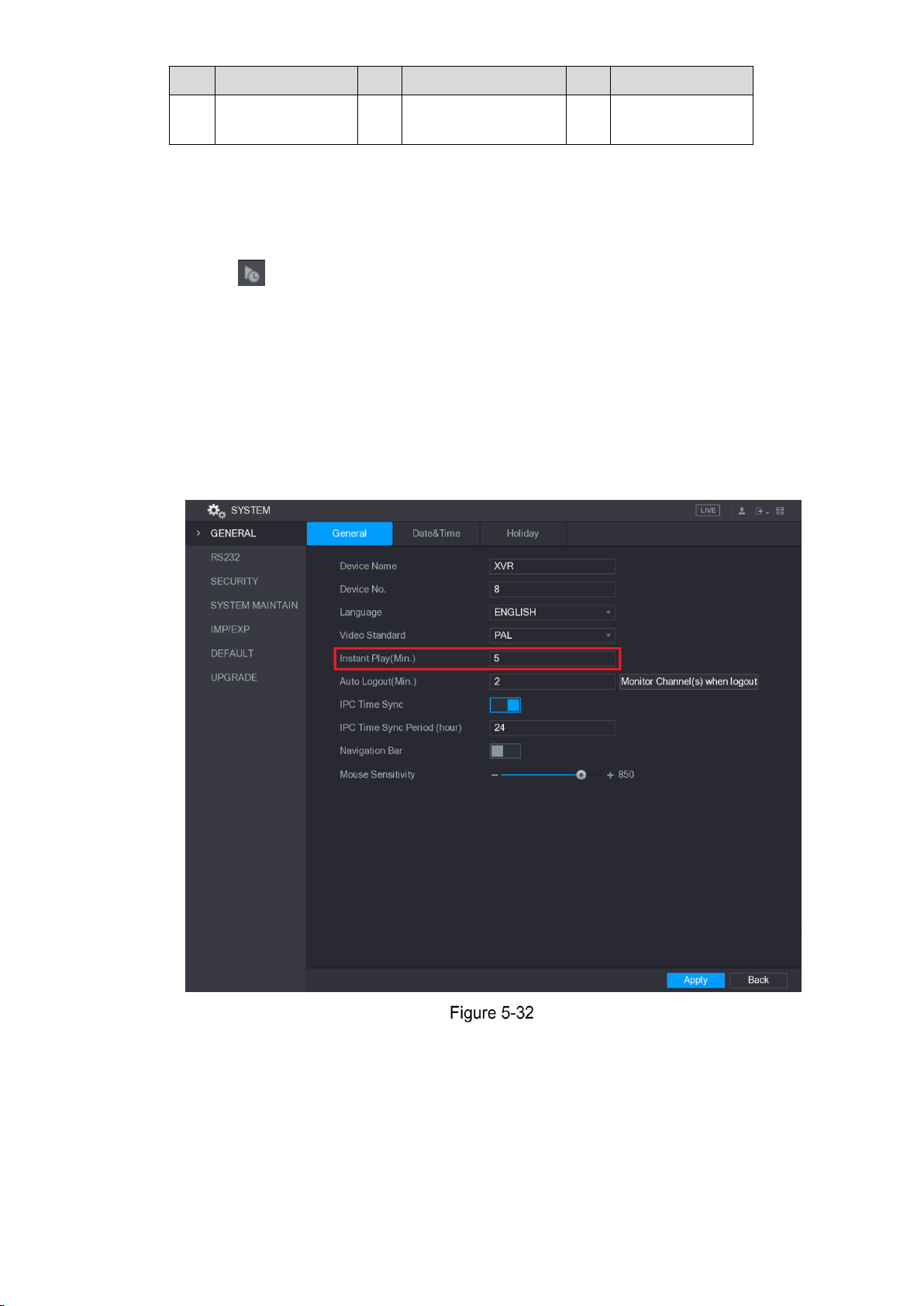
Local Configurations 54
No.
Function
No.
Function
No.
Function
3
Real-time
Backup
6
Audio Talk
5.2.2.1 Instant Playback
You can play back the previous five minutes to sixty minutes of the recorded video.
By clicking , the instant playback interface is displayed. The instant playback has the
following features:
Move the slider to choose the time you want to start playing.
Play, pause and close playback.
The information such as channel name and recording status icon are shielded during
instant playback and will not display until exited.
During playback, screen split layout switch is not allowed.
To change the playback time, select Main Menu > SYSTEM > GENERAL, in the Instant
Play box, enter the time you want to play back. See Figure 5-32.
5.2.2.2 Digital Zoom
You can enlarge a specific area of the image to view the details by either of the following two
ways.
Page 65

Local Configurations 55
Click , the icon switches to . Hold down the left mouse button to select the area
you want to enlarge. The area is enlarged after the left mouse button is released.
Point to the center that you want to enlarge, rotate the wheel button to enlarge the area.
For some models, when the image is enlarged in the first way described previously, the
selected area is zoomed proportionally according to the window.
When the image is in the enlarged status, you can drag the image toward any direction to
view the other enlarged areas.
Right-click on the enlarged image to return the original status.
5.2.2.3 Real-time Backup
You can record the video of any channel and save the clip into a USB storage device.
By clicking , the recording is started. To stop recording, click this icon again. The clip is
automatically saved into the connected USB storage device.
5.2.2.4 Manual Snapshot
You can take one to five snapshots of the video and save into a USB storage device.
By clicking , you can take snapshots. The snapshots are automatically saved into the
connected USB storage device. You can view the snapshots on your PC.
To change the quantity of snapshots, select Main Menu > CAMERA > ENCODE > Snapshot,
in the Manual Snap list, select the snapshot quantity.
5.2.2.5 Mute (Analog channel only)
You can mute the video sound by clicking . This function is supported in single-channel
view.
5.2.2.6 Bidirectional Talk (Digital channel only)
You can perform the voice interaction between the Device and the remote device to improve
efficiency of emergency. This function is supported only when the remotely connected IPC
device supports bidirectional talk.
Click , the icon switches to , the bidirectional talk of the remote device is turned on.
The bidirectional talk of other digital channels is disabled.
Click to cancel the bidirectional talk. The bidirectional talk of other digital channels is
resumed.
Page 66
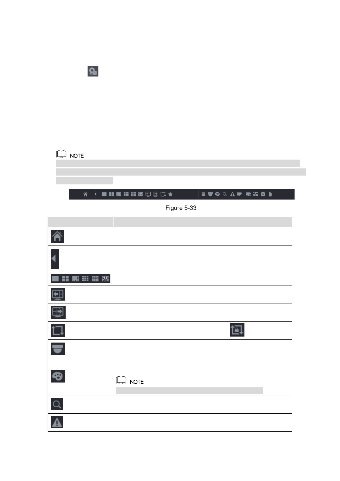
Local Configurations 56
5.2.2.7 Remote Devices (Digital channel only)
You can view the information of remote devices and add new remote devices to replace the
current connected devices.
By clicking , the Camera Registration interface is displayed. For details about adding the
remote devices, see "5.6 Configuring Remote Devices."
5.2.3 Navigation Bar
You can access the functions to perform operations through the function icons on the
navigation bar. For example, you can access Main Menu and switch window split mode. See
Figure 5-33.
The navigation bar is disabled by default. It does not appear in the live view screen until it is
enabled. To enable it, select Main Menu > SYSTEM > GENERAL, enable the Navigation Bar,
and then click Apply.
Icon
Function
Open Main Menu.
Expand or condense the navigation bar.
Select view layout.
Go to the previous screen.
Go to the next screen.
Enable tour function. The icon switches to .
Open the PTZ control panel. For details, see "5.4 Controlling PTZ
Cameras."
Open the Color Setting interface. For details, see "5.2.5 Color
Setting."
This function is supported only in single-channel layout.
Open the record search interface. For detail, see "5.9 Playing
Back Video."
Open the EVENT interface to view the device alarm status. For
details, see "5.19.3 Viewing Event Information."
Page 67
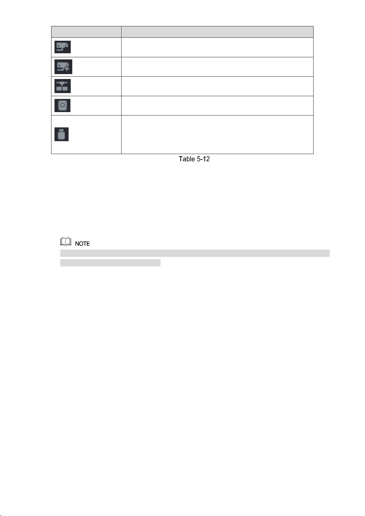
Local Configurations 57
Icon
Function
Open the CHANNEL INFO interface to display the information of
each channel.
Open the CAMERA REGISTRATION interface. For details, see
"5.6.1 Adding Remote Devices."
Open the NETWORK interface. For details, see "5.14.1
Configuring Network Settings."
Open the HDD MANAGER interface. For details, see "5.17.3
Configuring HDD Manager."
Open the USB MANAGER interface. For details about USB
operations, see "5.13.2 Backing up Files", "5.19.2 Viewing Log
Information", "5.18.5 Exporting and Importing System Settings",
"5.18.7 Upgrading the Device."
5.2.4 Shortcut Menu
You can quickly access some function interfaces such as main menu, record search, PTZ
setting, color setting and select the view split mode.
Right-click on the live view screen, the shortcut menu is displayed. See Figure 5-34. For details
about the functions of shortcut menu, see Table 5-13.
After you access any interface through shortcut menu, you can return to the previous screen by
right-clicking on the current screen.
Page 68

Local Configurations 58
Function
Description
Main Menu
Open Main Menu interface.
Search
Open the PLAYBACK interface where you can search and play
back record files.
PTZ
Open the PTZ interface.
View Layout
Configure the live view screen as a single-channel layout or
multi-channel layout.
Previous Screen
Click Previous Screen to go to the previous screen. For example, if
you are using 4-split mode, the first screen is displaying the
channel 1-4, click Next screen, you can view channel 5-8.
Next Screen
Camera Registration
Open the CAMERA REGISTRATION interface. For details, see
"5.6 Configuring Remote Devices
Adding Remote Devices."
Manual
Select Record, you can configure the recording mode as
Auto or Manual, or stop the recording. You can also enable or
disable snapshot function
Select Alarm Out, you can configure alarm output settings.
Preview Mode
Select General, the layout of live view screen is as default.
Select Show Face List, the detected face snapshots are
displayed in the bottom of the live view screen.
Auto Focus
Point to the channel window and right-click on it to open the
shortcut menu, and then click Auto Focus.
Page 69

Local Configurations 59
Function
Description
Not all cameras support this function.
Color Setting
Open the COLOR interface where you can adjust the video image
color.
Image
Click to modify the camera properties.
5.2.5 Color Setting
You can adjust the video image color effect such as sharpness, brightness, and contrast. The
parameters are different according to the connected camera type. Take analog channel as an
example.
In the live view screen, right-click on the analog channel to see the shortcut menu, and then
select Color Setting, the COLOR interface is displayed. See Figure 5-35.
For details, see "5.5.1 Configuring Image Settings."
Parameter
Description
Period
Divide 24 hours into two periods and configure the corresponding
color settings.
Effective Time
Enable the function and then set the effective time for each period.
Sharpness
Adjust the sharpness of image edge. The bigger the value is, the
more obvious the image edge, and the noise is also greater.
The value ranges from 1 to 15. The default value is 1.
Page 70
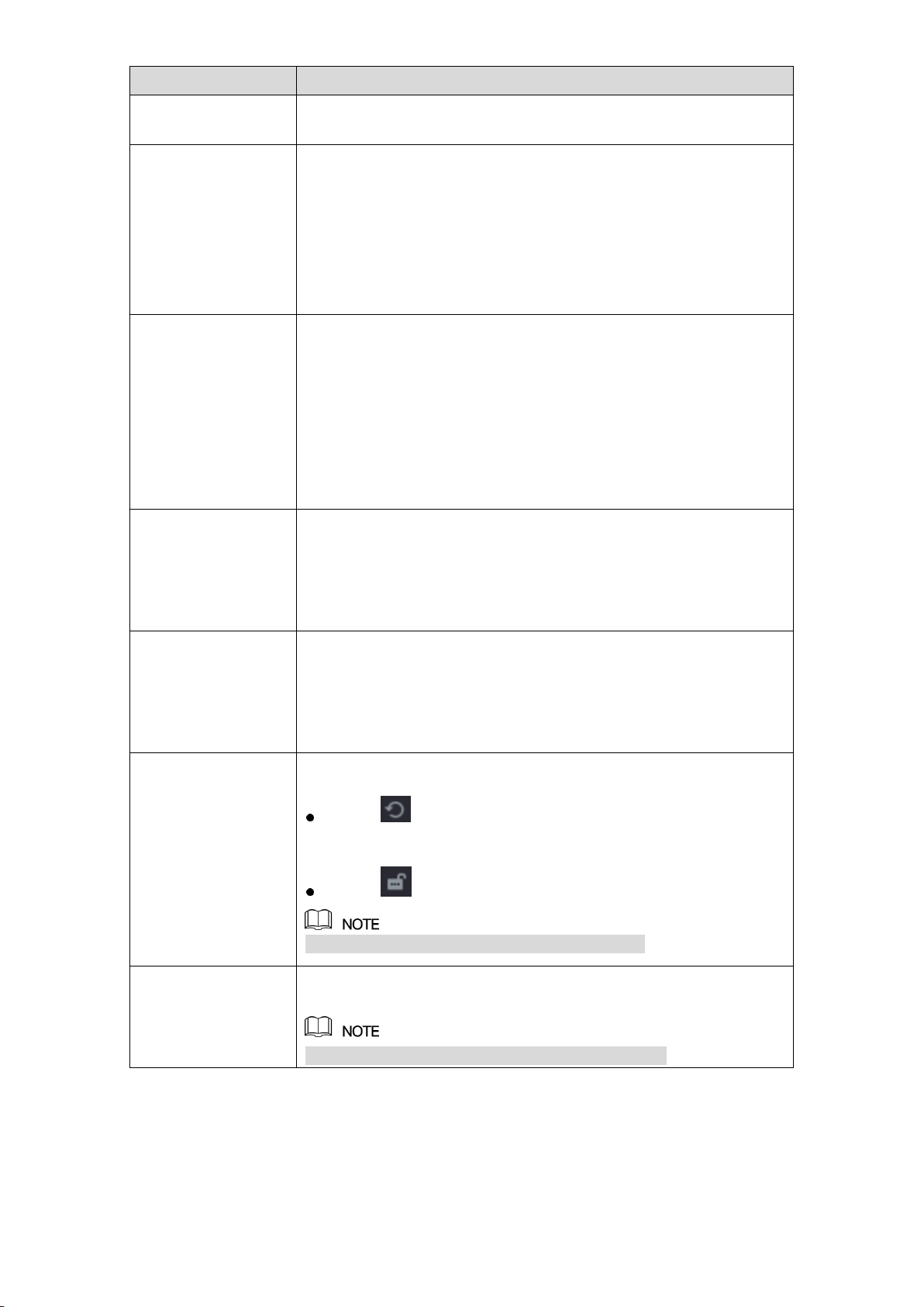
Local Configurations 60
Parameter
Description
Hue
Adjust the hue of image. The value ranges from 0 to 100. The
default value is 50.
Brightness
Adjust the image brightness. The value ranges from 0 to 100. The
default value is 50.
The bigger the value is, the brighter the image will become. You
can adjust this value when the image as a whole looks dark or
bright. However, the image is likely to become dim if the value is
too big.
The recommended range is between 40 and 60.
Contrast
Adjust the image contrast. The bigger the value is, the more
obvious the contrast between the light area and dark area will
become. You can adjust this value when the contrast is not
obvious. However, if the value is too big, the dark area is likely to
become darker and the light area over exposed. If the value is too
small, the image is likely to become dim.
The value ranges from 0 to 100. The default value is 50. The
recommended range is between 40 and 60.
Saturation
Adjust the color shades. The bigger the value, the lighter the color
will become. This value does not influence the general image
lightness.
The value ranges from 0 to 100. The default value is 50. The
recommended range is between 40 and 60.
Color Mode
In the Color Mode list, you can select Standard, Soft, Bright,
Colorful, Bank, Customized 1, Customized 2, Customized 3,
and Customized 4.
The sharpness, hue, brightness, contrast and saturation will adjust
automatically according to the selected color mode.
EQ
Enhance the image effect. Adjust the effect value.
Click , image is adjusted to the optimized effect
automatically.
Click , the current effect setting will be locked.
Only HD analog channel supports this function.
Position
Adjust the display position of the image in the channel window. The
value indicates pixel. The default value is 16.
This function is only supported by analog channel.
Page 71

Local Configurations 61
Parameter
Description
Customized
You can customize four color modes.
1. Click Customized. The Customized Color interface is
displayed.
2. In the Color Mode list, select Customized 1, for example.
Then configure the settings for sharpness, hue, brightness,
contrast and saturation. If you select All, the configuration will
applies to all four customized color modes.
3. Click OK.
4. On the COLOR interface, in the Color Mode list, you can
select the customized color mode.
5.2.6 Live View Display
5.2.6.1 Configuring Display Settings
You can configure the display effect such as displaying time title and channel title, adjusting
image transparency, and selecting the resolution.
Select Main Menu > DISPLAY > Display.
The DISPLAY interface is displayed. See Figure 5-36.
Configure the settings for the display parameters. See Table 5-15.
Parameter
Description
Page 72

Local Configurations 62
Parameter
Description
Main
Screen
Out Port
Indicates the main screen port.
Time Title
Select the Time Title check box, the current system time
displays in each channel window in live view screen. To hide
the time, clear the check box.
Channel Title
Select the Channel Title check box, the channel name,
channel number and recording status display in each channel
window in live view screen. To hide the time, clear the check
box.
Original Rate
Select the Original Rate check box, the video image displays
in its actual size in the channel window.
IVS Rule
Preview
Select the IVS Rule Preview check box to enable IVS rule
preview function.
Transparency
Configure the transparency of the graphical user interface
(GUI). The higher the value, the more transparent the GUI
becomes.
Resolution
Select resolution for the video. The default resolution for VGA
port and HDMI port is 1280×1024.
Some of the resolution options might not be supported on the
HDMI port.
Preview Mode
General: No information is displayed on the channel
window.
Show Face List: Displays the detected face snapshots
taken as a result of face detection on the bottom of the
live view screen.
Not all models support this function.
Extra
Screen
Enable
Enable extra screen function. After this function is enabled,
you can select which port as extra screen port, and the other
port automatically becomes the main screen port.
Out Port
Select the VGA port or HDMI port as the port connected by a
secondary monitor. For example, if you select HDMI port as
the extra screen port, the VGA port automatically becomes
the main screen port.
Resolution
Select resolution for the video. The default resolution for VGA
port and HDMI port is 1280×720.
Some of the resolution options might not be supported on the
HDMI port.
The main menu does not display on the extra screen.
If you do not enable the extra screen function, both the VGA port and HDMI port
display the same image.
Page 73
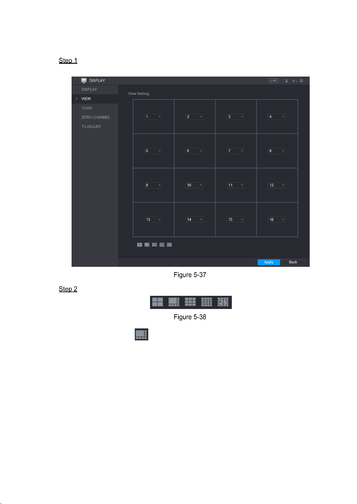
Local Configurations 63
5.2.6.2 Configuring Viewing Layout
You can configure the view layout in the live view screen.
Select Main Menu > DISPLAY > VIEW.
The View Setting interface is displayed. See Figure 5-37.
Configure the view layout by clicking the layout buttons on the bottom. See Figure 5-38.
For example, click and select 9-16, the view layout changes immediately, see
Figure 5-39.
Page 74

Local Configurations 64
Adjust the position of channels if needed.
In the channel list, for example, in the channel 9 list, you can select 10, and then the
channel 9 and channel 10 exchange positions.
Click Apply to complete the settings.
The live view screen displays the same layout as configured in this section.
5.2.6.3 Configuring Zero-Channel Settings
You can view several video sources on one channel on the web end.
Select Main Menu > DISPLAY > ZERO-CHANNEL.
The ZERO-CHANNEL interface is displayed. See Figure 5-40.
Page 75

Local Configurations 65
Configure the settings for the zero-channel parameters. See Table 5-16.
Parameter
Description
Enable
Enable zero-channel function.
Compression
In the Compression list, select the video compression standard
according to the device capability. The default is H.264.
Resolution
In the Resolution list, select the video resolution. The default is
704×576 (D1).
Frame Rate
(FPS)
Select a value between 1 and 25 for PAL standard, and between 1
and 30 for NTSC standard. The actual arrange is decided and
selected dependent on the Device capability.
Bit Rate (Kb/S)
The default value is 1024Kb/S. The actual arrange is decided and
selected dependent on the Device capability and frame rate.
Click Apply to save the settings.
In the live interface on the web, click to select one of the
multi-channel modes, and then you can view the local video image.
5.2.6.4 Configuring TV
Not all models support this function.
Page 76
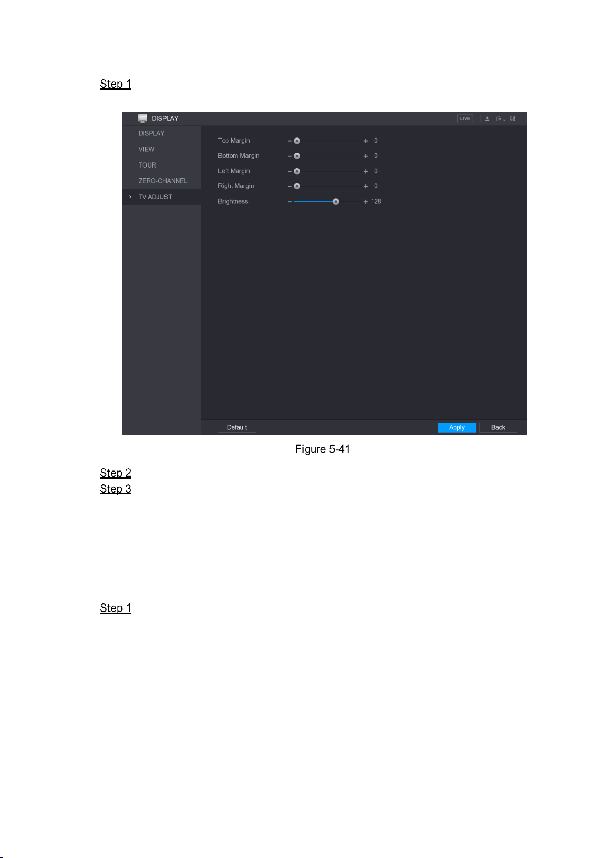
Local Configurations 66
You can adjust the border margins in top, bottom, left and right directions as well as the
brightness of the monitor connected to the Video out port of the Device.
Select Main Menu > DISPLAY > TV ADJUST.
The TV ADJUST interface is displayed. See Figure 5-41.
Configure the parameters according to your actual situation.
Click Apply to complete the settings.
5.2.7 Configuring Tour Settings
You can configure a tour of selected channels to repeat playing videos. The videos display in
turn according to the channel group configured in tour settings. The system is playing one
channel group for a certain period and then automatically changes to the next channel group.
Select Main Menu > DISPLAY > TOUR.
The TOUR interface is displayed. There are Main Screen tab and Extra Screen tab,
see Figure 5-42 and Figure 5-43.
Page 77

Local Configurations 67
Configure the settings for the tour parameters for both Main Screen and Extra Screen.
See Table 5-17.
Page 78

Local Configurations 68
Parameter
Description
Enable
Enable tour function.
Interval (Sec.)
Enter the amount of time that you want each channel group displays
on the screen. The value ranges from 5 seconds to 120 seconds, and
the default value is 5 seconds.
Video Detect,
Alarm
Select the View 1 or View 8 for Motion Detect tour and Alarm Tour
(system alarm events).
Window Split
In the Window Split list, select View 1, View 4, View 8, or other
modes that are supported by the Device.
Channel Group
Display all channel groups under the current Window Split setting.
Add a channel group: Click Add, in the pop-up Add Group
channel, select the channels to form a group, and then click
Save.
Delete a channel group: Select the check box of any channel
group, and then click Delete.
Edit a channel group: Select the check box of any channel group
and then click Modify, or double-click on the group. The Modify
Channel Group dialog box is displayed. You can regroup the
channels.
Click Move up or Move down to adjust the position of channel
group.
Click Apply to save the settings.
On the top right of the live view screen, use the left mouse button or press Shift to
switch between (image switching is allowed) and (image switching is
not allowed) to turn on/off the tour function.
On the navigation bar, click to enable the tour and click to disable it.
Adding a Channel Group
Click Add.
The Add Group interface is displayed. See Figure 5-44.
Page 79

Local Configurations 69
Select the channels that you want to group for tour. See Figure 5-45.
If you want to select more than one channel, in the Window Split list, do not select
View 1.
Click OK to complete the settings.
Modifying a Channel Group
Double-click on a channel group, the Modify Channel Group interface is displayed. See
Figure 5-46.
You can modify channel group and click OK to complete the settings.
5.3 Entering Main Menu
Right-click on the live view screen, the shortcut menu is displayed, Click Main Menu and then
login the system. The Main Menu is displayed, see Figure 5-47.
Page 80
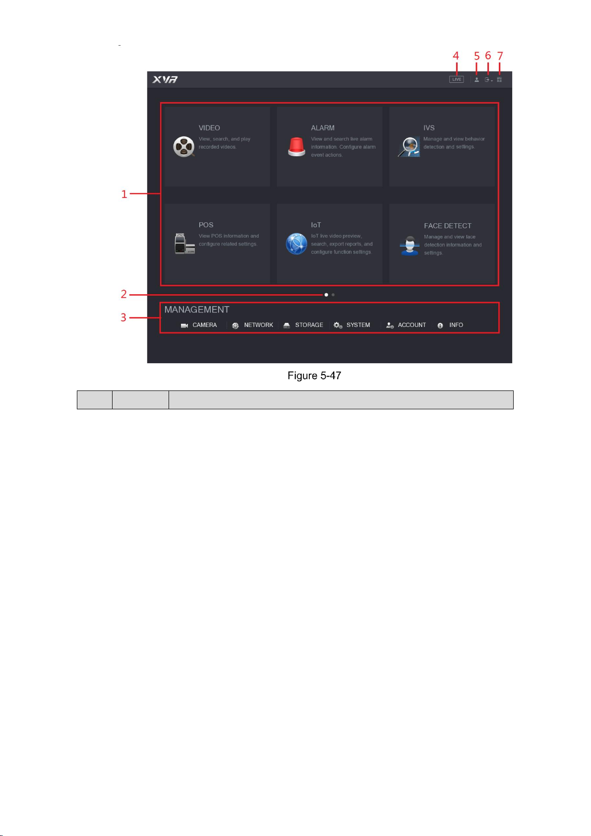
Local Configurations 70
No.
Icon
Description
Page 81
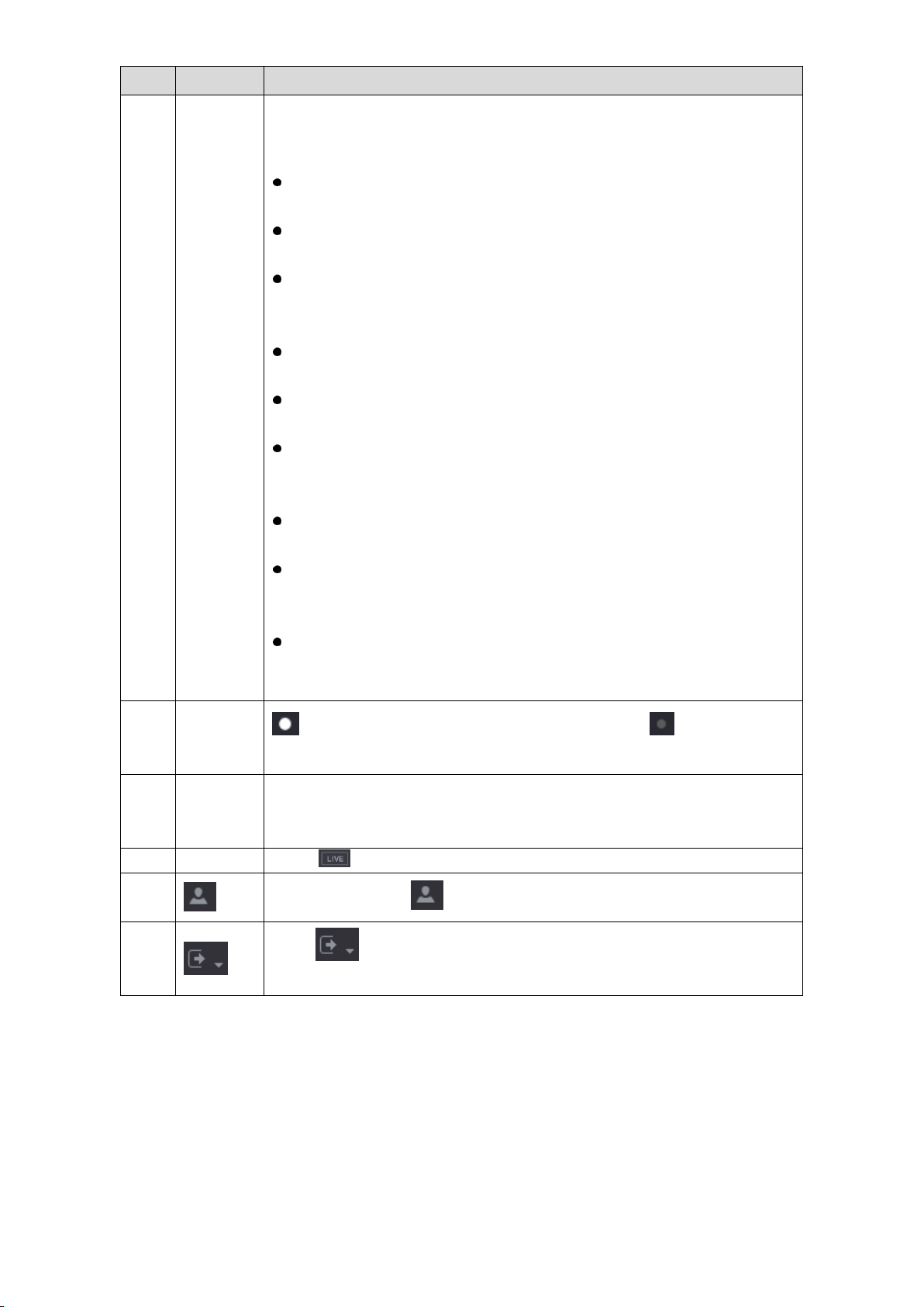
Local Configurations 71
No.
Icon
Description
1
Function
tiles
Includes eight function tiles: VIDEO, ALARM, IVS, POS, IoT, AI,
BACKUP, DISPLAY, and AUDIO. Click each tile to open the
configuration interface of the tile.
VIDEO: Search for and play back the recorded video saved on the
Device.
ALARM: Search for alarm information and configure alarm event
actions.
IVS: Configure the behavior detections by drawing rules for
detecting tripwire, intrusion, abandoned objects, and missing
objects.
POS: You can connect the Device to the POS (Point of Sale)
machine and receive the information from it.
FACE DETECT: Configure the human faces detection settings and
search detected human faces.
IoT: View, search and export the temperature and humidity data of
camera, connect sensors and wireless siren, and configure the
alarm event linkage settings.
BACKUP: Search and back up the video files to the local PC or
external storage device such as USB storage device.
DISPLAY: Configure the display effect such as displaying content,
image transparency, and resolution, and enable the zero-channel
function.
AUDIO: Manage audio files and configure the playing schedule. The
audio file can be played in response to an alarm event if the voice
prompts function is enabled.
2
Switch
icon
indicates the current page of main menu. Click to switch to the
next page.
3
Configura
tion menu
Includes six configurations through which you can configure camera
settings, network settings, storage settings, system settings, account
settings, and view information.
4
Live
Click to go to the live view screen.
5
When you point to , the current user account is displayed.
6
Click , select Logout, Reboot, or Shutdown according to your
actual situation.
Page 82

Local Configurations 72
No.
Icon
Description
7
Displays Cell Phone Client and Device SN QR Code.
Cell Phone Client: Use your mobile phone to scan the QR code to
add the device into the Cell Phone Client, and then you can start
accessing the Device from your cell phone.
Device SN: Obtain the Device SN by scanning the QR code. Go to
the P2P management platform and add the Device SN into the
platform. Then you can access and manage the device in the WAN.
For details, please refer to the P2P operation manual. You can also
configure P2P function in the local configurations. See "5.1.4.5
Configuring P2P Settings."
5.4 Controlling PTZ Cameras
PTZ is a mechanical platform that carries a camera and a protective cover and performs overall
control remotely. A PTZ can move in both horizontal and vertical direction to provide all-around
view to the camera.
Before operating PTZ, please assure the network connection between PTZ and the Device.
5.4.1 Configuring PTZ Connection Settings
You need to configure the PTZ connection settings before use.
Local connection: RS485 Port for connecting Speed Dome or coaxial cable for connecting
coaxial camera.
Remote connection: local area network.
Select Main Menu > CAMERA > PTZ.
The PTZ interface is displayed. See Figure 5-48.
Page 83

Local Configurations 73
Configure the settings for the PTZ connection parameters. See Table 5-19.
Parameter
Description
Channel
In the Channel list, select the channel that you want to connect the PTZ
camera to.
PTZ Type
Local: Connect through RS485 port or coaxial cable.
Remote: Connect through network by adding IP address of PTZ
camera to the Device.
Control Mode
In the Control Mode list, select Serial or HDCVI. For HDCVI series
product, please select HDCVI. The control signal is sent to the PTZ
through the coaxial cable. For the serial mode, the control signal is sent to
the PTZ through the RS485 port.
Protocol
In the Protocol list, select the protocol for the PTZ camera, for example,
select HDCVI3.0.
Address
In the Address box, enter the address for PTZ camera. The default is 1.
The entered address must be the same with the address configured on
the PTZ camera; otherwise the PTZ camera cannot be controlled from
the Device.
Baudrate
In the Baudrate list, select the baudrate for the PTZ camera. The default
is 9600.
Data Bits
The default is 8.
Stop Bits
The default is 1.
Parity
The default is NONE.
Page 84

Local Configurations 74
Click Apply to save the settings.
Click Copy to copy the settings to other channels.
5.4.2 Working with PTZ Control Panel
PTZ control panel performs the operations such as directing camera in eight directions,
adjusting zoom, focus and iris settings, and quick positioning.
Basic PTZ Control Panel
Right-click on the live view screen and then select PTZ. The PTZ control panel is displayed.
See Figure 5-49.
The functions with buttons in gray are not supported by the system.
Parameter
Description
Speed
Controls the movement speed. The bigger the value is, the faster the
movement will be.
Zoom
: Wide angle.
: Long shot.
Focus
: Zoom in.
: Zoom out.
Iris
: Small.
: Large.
PTZ movement
Supports eight directions.
Fast positioning button.
Positioning: Click to enter the fast positioning screen, and
then click anywhere on the live view screen, the PTZ will turn to
this point and move it to the middle of the screen.
Zooming: On the fast positioning screen, drag to draw a square on
Page 85

Local Configurations 75
Parameter
Description
the view. The square supports zooming.
Dragging upward is to zoom out, and dragging downward is to
zoom in.
The smaller the square, the larger the zoom effect.
Not all models support this function and can only be controlled through
mouse operations.
Click , you can control the four directions (left, right, up, and down)
PTZ movement through mouse operation.
Click to open the expanded PTZ control panel.
Expanded PTZ Control Panel
On the basic PTZ control panel, click to open the expanded PTZ control panel to find more
options. See Figure 5-50.
The functions with buttons in gray are not supported by the system.
Right-click once to return to the interface of PTZ basic control panel.
Icon
Function
Icon
Function
Preset
Auto Pan
Tour
Flip
Pattern
Reset
Autoscan
Click the AUX Config icon to open
the PTZ functions settings interface.
AUX Switch
Click the Enter Menu icon to open
the MENU OPERATION interface.
Page 86
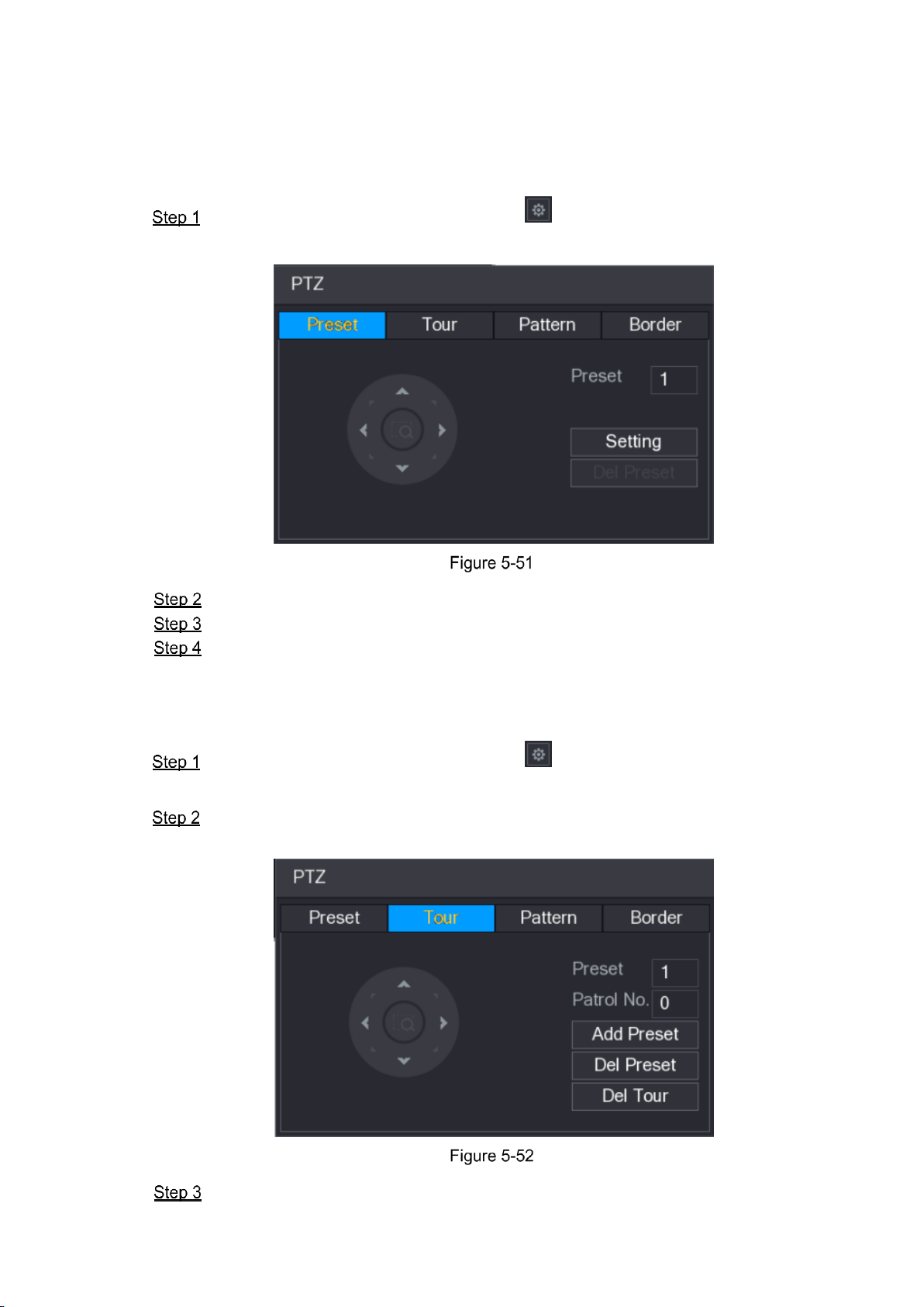
Local Configurations 76
5.4.3 Configuring PTZ Functions
5.4.3.1 Configuring Presets
On the Expanded PTZ Control Panel, click .
The Preset interface is displayed. See Figure 5-51.
Click the direction arrows to the required position.
In the Preset box, enter the value to represent the required position.
Click Setting to complete the preset settings.
5.4.3.2 Configuring Tours
On the Expanded PTZ Control Panel, click .
The PTZ interface is displayed.
Click the Tour tab.
The Tour tab is displayed. See Figure 5-52.
In the Patrol No. box, enter the value for the tour route.
Page 87
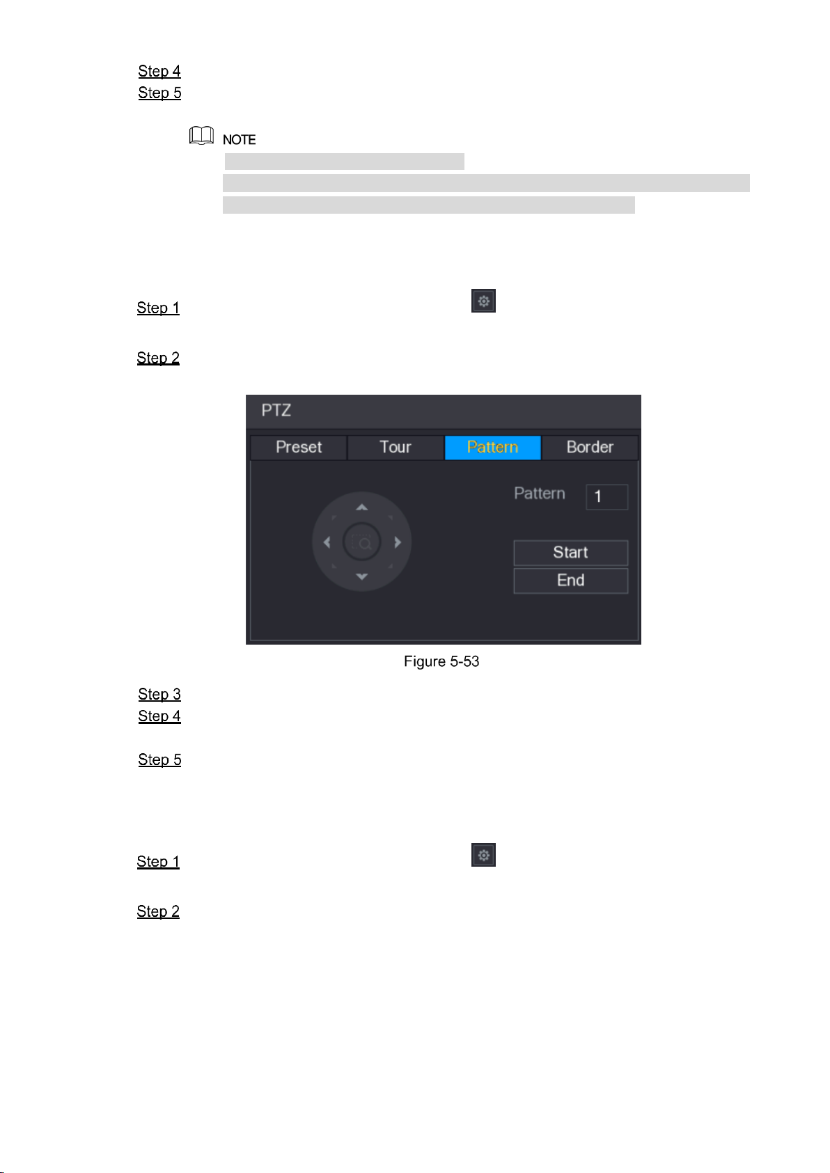
Local Configurations 77
In the Preset box, enter the preset value.
Click Add Preset.
A preset will be added for this tour.
You can repeat adding more presets.
Click Del Preset to delete the preset for this tour. This operation can be repeated
to delete more presets. Some protocols do not support deleting.
5.4.3.3 Configuring Patterns
On the Expanded PTZ Control Panel, click .
The PTZ interface is displayed.
Click the Pattern tab.
The Pattern interface is displayed. See Figure 5-53.
In the Pattern box, enter the value for pattern.
Click Start to perform the directions operations. You can also go to the PTZ Control
Panel to perform the operations of adjusting zoom, focus, iris, and directions.
On the PTZ interface, click End to complete the settings.
5.4.3.4 Configuring AutoScan
On the Expanded PTZ Control Panel, click .
The PTZ interface is displayed.
Click the Border tab.
The Border interface is displayed. See Figure 5-54.
Page 88

Local Configurations 78
Click the direction arrows to position the left and right borders.
5.4.4 Calling PTZ Functions
After you have configured the PTZ settings, you can call the PTZ functions for monitoring from
the Expanded PTZ Control Panel. See Figure 5-55.
5.4.4.1 Calling Presets
On the Expanded PTZ Control Panel, in the No. box, enter the value of the preset that
you want to call.
Click to call the preset.
Click again to stop calling the preset.
5.4.4.2 Calling Tours
On the Expanded PTZ Control Panel, in the No. box, enter the value of the tour that
you want to call.
Click to call the tour.
Click again to stop calling the tour.
Page 89
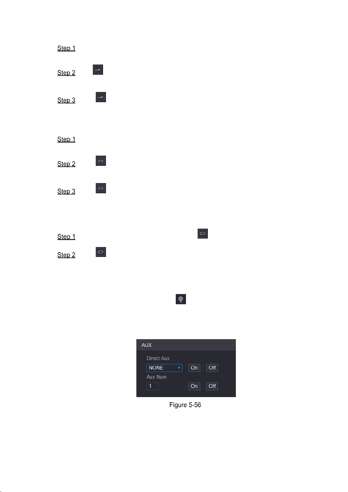
Local Configurations 79
5.4.4.3 Calling Patterns
On the Expanded PTZ Control Panel, in the No. box, enter the value of the pattern that
you want to call.
Call to call the pattern.
The PTZ camera moves according to the configured pattern repeatedly.
Click again to stop calling the pattern.
5.4.4.4 Calling AutoScan
On the Expanded PTZ Control Panel, in the No. box, enter the value of the border that
you want to call.
Click .
The PTZ camera performs scanning according to the configured borders.
Click again to stop auto canning.
5.4.4.5 Calling AutoPan
On the Expanded PTZ Control Panel, click to start moving in horizontal direction.
Click again to stop moving.
5.4.4.6 Using AUX Button
On the Expanded PTZ Control Panel, click , the AUX setting interface is displayed. See
Figure 5-56.
In the Direct Aux list, select the option that corresponds to the applied protocol.
In the Aux Num box, enter the number that corresponds to the AUX switch on the decoder.
5.4.5 Calling OSD Menu
For the coaxial camera, you can call the OSD menu through the Expanded PTZ Control Panel.
See Figure 5-55.
Page 90

Local Configurations 80
On the Expanded PTZ Control Panel, click .
The MENU OPERATION interface is displayed. See Figure 5-57.
Click Enter.
The OSD menu is displayed. See Figure 5-58.
On the MENU OPERATION interface, click the arrow button to select the onscreen
parameters.
Click Enter to complete the settings.
5.5 Configuring Camera Settings
5.5.1 Configuring Image Settings
You can configure the image settings such as saturation, contrast, brightness, sharpness for
each connected camera.
Select Main Menu > CAMERA > IMAGE.
The IMAGE interface is displayed. See Figure 5-59 for analog channel and Figure 5-60
for digital channel.
Page 91
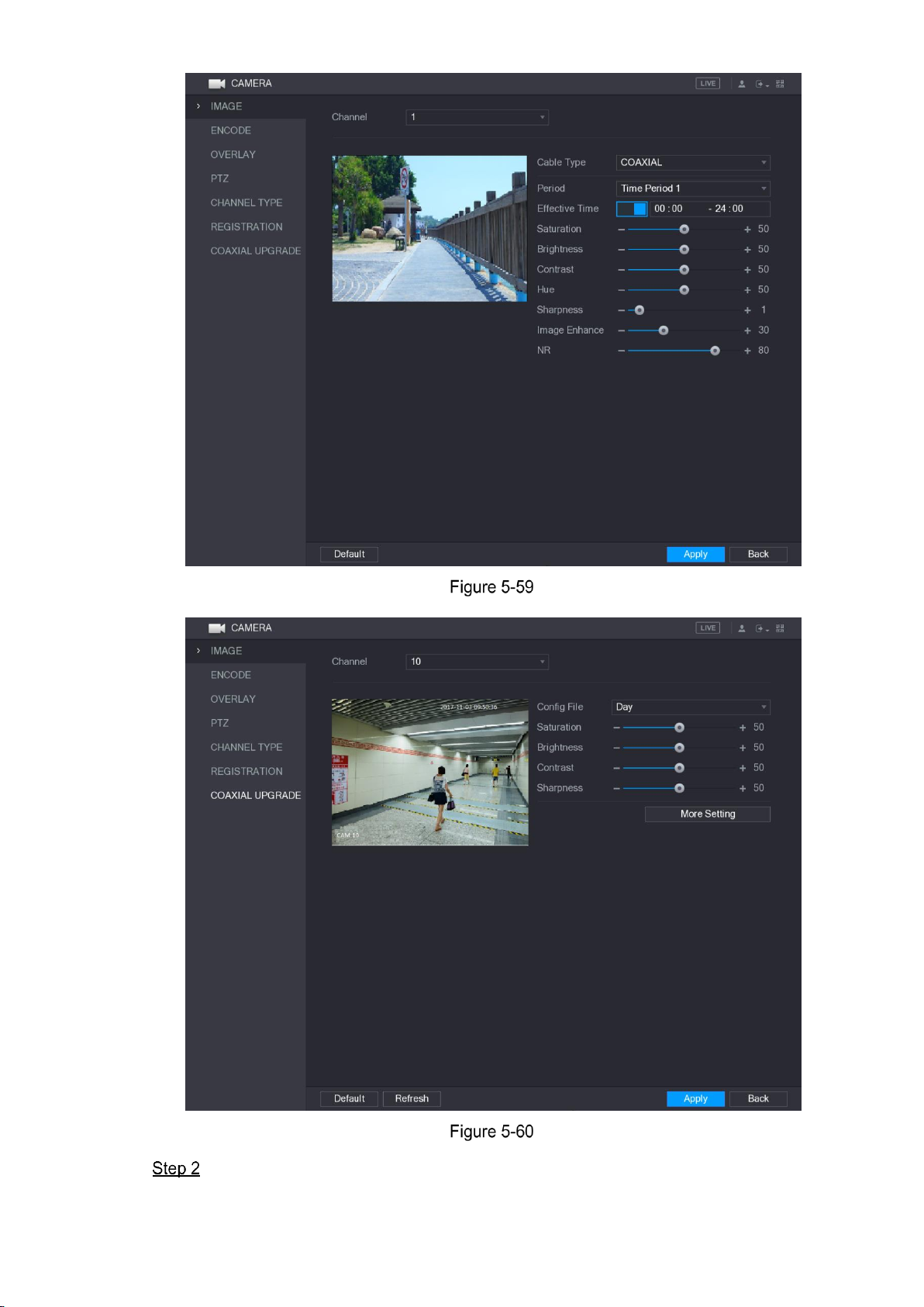
Local Configurations 81
Configure the settings for the image parameters. See Table 5-22.
On the digital channel interface, click More Setting to display more parameters.
Page 92

Local Configurations 82
Parameter
Description
Channel
In the Channel list, select the channel that you want to configure.
Cable Type
In the Cable Type list, select the cable type that the camera uses.
Not all models support this function.
Period
In the Period list, select a time period for the image settings. The
image settings will be only used during the selected period.
Effective Time
Enable the effective function.
In the Effective Time box, enter the start time and end time for the
period you selected.
Saturation
Adjusts the color shades. The bigger the value, the lighter the color
will become. This value does not influence the general image
lightness.
The value ranges from 0 to 100. The default value is 50. The
recommended range is between 40 and 60.
Contrast
Adjusts the image contrast. The bigger the value is, the more obvious
the contrast between the light area and dark area will become. You
can adjust this value when the contrast is not obvious. However, if the
value is too big, the dark area is likely to become darker and the light
area over exposed. If the value is too small, the image is likely to
become dim.
The value ranges from 0 to 100. The default value is 50. The
recommended range is between 40 and 60.
Brightness
Adjusts the image brightness. The bigger the value is, the brighter the
image will become. You can adjust this value when the image as a
whole looks dark or bright. However, the image is likely to become dim
if the value is too big.
The value ranges from 0 to 100. The default value is 50. The
recommended range is between 40 and 60.
Hue
Adjusts the hue of image. The value ranges from 0 to 100. The default
value is 50.
Sharpness
Adjusts the sharpness of image edge. The bigger the value is, the
more obvious the image edge, and the noise is also greater.
The value ranges from 1 to 15. The default value is 1.
Image Enhance
Adjusts the image definition. The bigger the value is, the clearer the
image will become, but there will be more noises.
NR
Reduces the noises from image. The bigger the value is, the better
the image will become.
Config File
In the Config File list, select Day, Night, Normal, or Switch By
Period. The system configures the parameters correspondingly.
Day: Apply the configuration during daytime.
Night: Apply the configuration during nighttime.
Normal: Apply the configuration during day and night.
Switch by Period: If you select this option, you need to configure
the sunrise time and sunset time where you are located.
Page 93

Local Configurations 83
Parameter
Description
Mirror
Enable the function, the left and right side of the video image will be
switched. It is disabled by default.
3D Denoise
This function specially applies to the image which frame rate is
configured as 2 at least. It reduces the noises by making use of the
information between two frames. The bigger the value is, the better
the effect.
Flip
In the Flip list, you can select 180° to change the video image display.
By default, the setting is No Flip.
Light
In the Light list, select Close or Enable to use the backlight
compensation or not.
Scene Mode
Configure the white balance to adjust the general hue of the image.
The default setting is Auto.
Auto: Automatically apply white balance to different colors to
make the image color display normally.
Sunny: Apply the threshold value to sunny environment.
Night: Apply the threshold value to night.
Customized: Manually adjust the Red Gain and Blue Gain values.
Day & Night
Configure the color and black&white mode of the image. This setting
is not affected by the configuration files. The default setting is Auto.
Color: The camera outputs color image only.
Auto: Depends on the camera, such as overall brightness and
whether there is an IR light, either color image or black&white
image is output.
B/W: The camera outputs Black and white image only.
By Time: The camera outputs image according to the configure
the sunrise time and sunset time.
Click Apply to complete the settings.
5.5.2 Configuring Encode Settings
Select Main Menu > CAMERA > ENCODE > Encode.
The Encode interface is displayed. See Figure 5-61.
Page 94

Local Configurations 84
Configure the settings for the main/sub streams parameters. See Table 5-23.
Parameter
Description
Channel
In the Channel list, select the channel that you want to configure the
settings for.
Smart Codec
Enable the smart codec function. This function can reduce the video
bit stream for non-important recorded video to maximize the storage
space.
Type
Main Stream: In the Type list, select General, MD (Motion
Detect), or Alarm.
Sub Stream: This setting is not configurable.
Compression
In the Compression list, select the encode mode.
H.265: Main profile encoding.
H.264H: High profile encoding. Low bit stream with high
definition. This setting is recommended.
H.264: General profile encoding.
H.264B: Baseline profile encoding. This setting requires higher bit
stream compared with other settings for the same definition.
Resolution
In the Resolution list, select resolution for the video.
The maximum video resolution might be different dependent on your
device model.
Page 95

Local Configurations 85
Parameter
Description
Frame Rate
(FPS)
Configure the frames per second for the video. The higher the value,
the clearer and smoother the image will become. Frame rate changes
along with the resolution.
Generally, in PAL format, you can select the value from 1 through 25;
in NTSC format, you can select the value from 1 through 30. However,
the specific range of frame rate that you can select depends on the
capability of the Device.
Quality
This function is available if you select VBR in the Bit Rate List.
The higher the value, the better the image will become.
I Frame Interval
The interval between two reference frames.
Bit Rate (Kb/S)
In the Bit Rate list, select a value or enter a customized value to
change the image quality. The bigger the value is, the better the
image will become.
Video
Enable the function for sub stream.
Audio Encode
Click More Setting, the More Setting interface is displayed.
Audio Encode: This function is enabled by default for main
stream. You need to manually enable it for sub stream 1. Once
this function is enabled, the recorded video file is composite
audio and video stream.
Audio Source: In the Audio Source list, you can select LOCAL
and HDCVI.
LOCAL: The audio signal is input from Audio input port.
HDCVI: The audio signal is input from HDCVI camera.
Audio Format: In the Audio Format list, select a format that you
need.
Audio Source
Audio Format
Click Apply to complete the settings.
Click Copy to copy the settings to other channels.
5.5.3 Configuring Snapshot Settings
Select Main Menu > CAMERA > ENCODE > Snapshot.
The Snapshot interface is displayed. See Figure 5-62.
Page 96
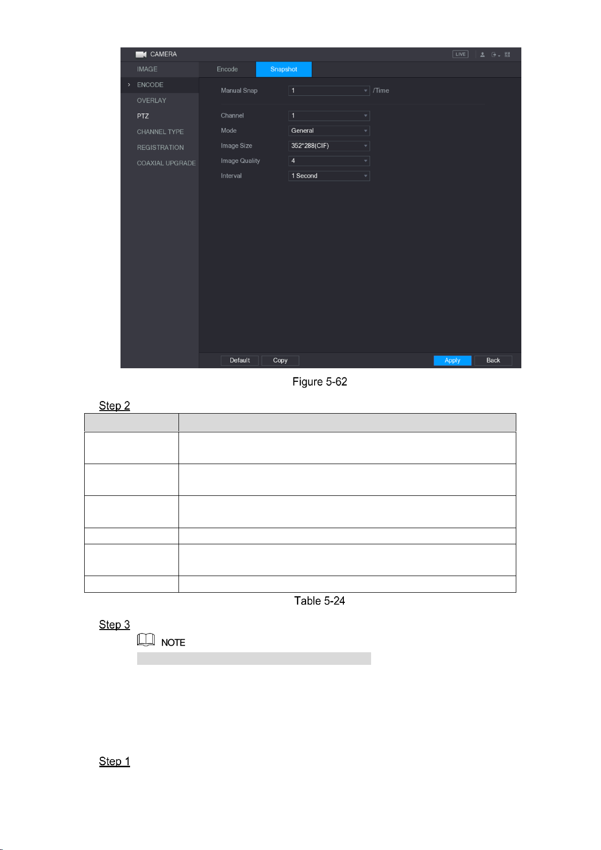
Local Configurations 86
Configure the settings for the snapshot parameters. See Table 5-24.
Parameter
Description
Manual Snap
In the Manual Snap list, select how many snapshots you want to take
each time.
Channel
In the Channel list, select the channel that you want to configure the
settings for.
Mode
In the Mode list, you can select Human Face, Event, or General as
the event type for which you want to take a snapshot.
Image Size
In the Image Size list, select a value for the image.
Image Quality
Configures the image quality by 6 levels. The higher the level, the
better the image will become.
Interval
Configures or customizes the snapshot frequency.
Click Apply to complete the settings.
Click Copy to copy the settings to other channels.
5.5.4 Configuring Overlay Settings
You can configure to display system time and channel name on each channel window in the live
view screen.
Select Main Menu > CAMERA > OVERLAY > Overlay.
The Overlay interface is displayed. See Figure 5-63.
Page 97

Local Configurations 87
Configure the settings for the text overlay parameters. See Table 5-25.
Parameter
Description
Channel
In the Channel list, select the channel that you want to configure the
settings for.
Time Display
Select the Time Display check box to display the system time on
each channel window in the live view screen.
In the Time Display list, select time display style.
Channel Title
Select the Channel Title check box to display the channel name on
each channel window in the live view screen.
In the Channel Title box, enter the name for the selected channel.
Click Apply to complete the settings.
Click Copy to copy the settings to other channels.
5.5.5 Configuring Covered Area Settings
Select Main Menu > CAMERA > OVERLAY > Cover-Area.
The Cover-Area interface is displayed. See Figure 5-64.
Page 98

Local Configurations 88
Configure the settings for the covered area parameters. See Table 5-26.
Parameter
Description
Channel
In the Channel list, select the channel that you want to configure the
settings for.
Preview
Preview: Select the Preview check box to apply the configured
covered block to the selected channel window in the live view
screen.
Record: Select the Record check box to apply the configured
covered block to the selected channel window during recording.
To configure covering block, do the following:
1. Select the Preview check box or the Record check box, or select
the both. The "1, 2, 3, 4" buttons are activated.
2. Click the buttons to select blocks.
3. A triangle solid black block is displayed. You can drag the block to
the area that you want to cover and adjust the size of the block.
4. You can configure total 4 covered blocks.
Record
Click Apply to complete the settings.
5.5.6 Configuring Channel Type
You can configure the channel type as Analog or IP channel.
Select Main Menu > CAMERA > CHANNEL TYPE.
Page 99
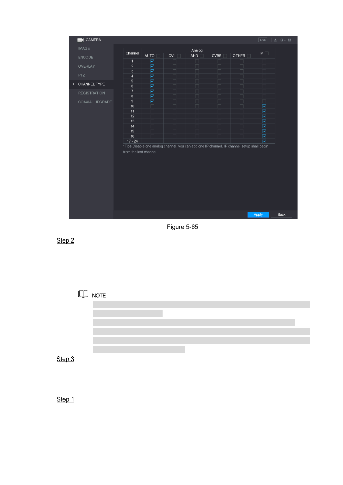
Local Configurations 89
The CHANNEL TYPE interface is displayed. See Figure 5-65.
Configure the channels.
Analog Channel: Select the transmission medium such as CVI, CVBS, and then
follow the onscreen instructions to complete the settings.
IP Channel: Select a channel for IP camera from the last channel number, for
example, in Figure 5-65, select from the 17–24 check box. Then follow the
onscreen instructions to complete the settings.
The 17–24 channels are only for IP camera and the range changes dependent on
the model you purchased.
The channel selection for analog camera or IP camera are in sequence, for
example, if you want to select channels for IP camera, you need to select the 17–
24 check box first, and then you cannot jump to select the channel 15 directly until
you have selected the channel 16.
Click Apply and follow the onscreen instructions to complete the settings.
5.5.7 Upgrading Coaxial Camera
Select Main Menu > CAMERA > COAXIAL UPGRADE.
The COAXIAL UPGRADE interface is displayed. See Figure 5-66.
Page 100
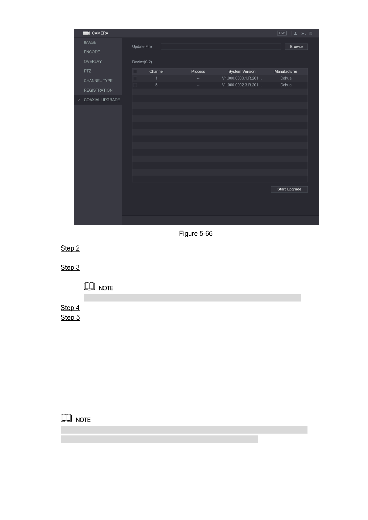
Local Configurations 90
Click Browse.
The Browse interface is displayed.
Select the upgrade file and click OK.
The COAXIAL UPGRADE interface is displayed.
You need to insert the USB storage device that contains the upgrading files.
Select the check box of the channel that you want to upgrade.
Click Start Upgrade.
If the upgrading is successful, the system pops up a message indicating the upgrading
is completed. If the upgrading is failed, please check if the Device
5.6 Configuring Remote Devices
5.6.1 Adding Remote Devices
This function is available after you have configured the channel type as IP channel as
described in previous section, see "5.5.6 Configuring Channel Type."
You can add remote devices by adding the IP address.
Select Main Menu > CAMERA > REGISTRATION > Registration, the Registration interface
is displayed. See Figure 5-67.
 Loading...