

Page 1

Block Camera User’s Manual
Version 1.1.1
Page 2

i
Welcome
Thank you for purchasing our block camera!
This user’s manual is designed to be a reference tool for your system.
Please read the following safeguard and warnings carefully before you use this series product!
Please keep this user’s manual well for future reference!
Page 3

ii
Important Safeguards and Warnings
1.Electrical safety
All installation and operation here should conform to your local electrical safety codes.
We assume no liability or responsibility for all the fires or electrical shock caused by improper
handling or installation.
We are not liable for any problems caused by unauthorized modification or attempted repair.
2.Transportation Security
No heavy stress, violent vibration or water splash are allowed during transportation, storage and
installation.
Please use the original packing material (or the material of the same quality) when you ship it back
to the manufacturer.
3.Installation
Do not apply power to the product before completing installation.
Do not put object on the product.
4.Environment
This series product should be installed in a cool, dry place away from direct sunlight, inflammable,
explosive substances and etc.
Please keep it away from the electromagnetic radiation object and environment.
Please keep the sound ventilation.
Do not allow the water and other liquid falling into the device.
Please make sure the CCD (CMOS) component is out of the radiation of the laser beam device.
Otherwise it may result in CCD (CMOS) optical component damage.
5. Daily Maintenance
Current series product has no power button. Please unplug all corresponding power cables before
your begin installation or daily maintenance work.
Please keep the dustproof cap back to protect the CCD or CMOS part if the device does not work
for a long time.
Do not touch CCD (CMOS) component. You can use the blower to clean the dust on the surface of
the device. You can use the dry cloth with some alcohol or mild detergent to clear if necessary.
Do not use the volatility solvent such as the benzene or thinner, or detergent with strong
abradibility. It may result in lens damage or it may adversely affect the device performance.
If there is too much dust, please use the water to dilute the mild detergent first and then use it to
clean the device. Finally use the dry cloth to clean the device
6. About Accessories
Always use all the accessories recommended by manufacturer.
Page 4

iii
Before installation, please open the package and check that all the components are included in the
package:
Contact you local retailer ASAP if something is missing in your package.
Page 5

iv
Table of Contents
1 General Introduction .................................................................................................................. 1
1.1 Overview ........................................................................................................................ 1
1.2 Features ......................................................................................................................... 1
2 Framework ................................................................................................................................... 2
2.1 Rear Panel ..................................................................................................................... 2
2.2 Side Panel ..................................................................................................................... 5
2.3 Front Panel .................................................................................................................... 5
3 Installation.................................................................................................................................... 7
3.1 Pedestal ......................................................................................................................... 7
3.2 SD Card ......................................................................................................................... 7
3.2.1 General Series ....................................................................................................... 7
3.2.2 Special Series ........................................................................................................ 8
Important ............................................................................................................................. 8
Please note, the following operation is for professional engineer only. We are not
liable for any problem resulting from the unauthorized operation. ............................ 8
3.3 Bidirectional Talk ........................................................................................................ 10
3.4 I/O Port ......................................................................................................................... 10
3.5 Lens Protection Film .................................................................................................. 11
4 Quick Configuration Tool ......................................................................................................... 12
4.1 Overview ...................................................................................................................... 12
4.2 Operation ..................................................................................................................... 12
5 Web Operation .......................................................................................................................... 15
5.1 Network Connection ................................................................................................... 15
5.2 Login and Logout ........................................................................................................ 15
Page 6

v
6 FAQ ............................................................................................................................................ 18
Appendix Toxic or Hazardous Materials or Elements ............................................................... 19
Page 7

1
1 General Introduction
1.1 Overview
This series camera integrates the traditional camera and network video technology. It adopts
audio/video data collection, transmission, and storage together.
This series network camera uses standard H.264 video compression technology, PCM,
G.711a/u audio compression technology and etc. It supports bidirectional talk, digital water
mark and etc.
This series network camera is widely used in many environments such as office, bank, road
monitor and etc.
1.2 Features
User Management
Different user rights for each group, one user belongs to one group.
The user right can not exceed the group right.
Data
Transmission
Support Ethernet transmission.
Support RS485 control function.
Support BNC analog video transmission.
Storage
Function
Support local storage and Micro SD card storage.
Support centralized storage.
Alarm Function
Support real-time video detect, internal abnormality detect, external alarm.
Alarm can activate snapshot, record, alarm output, email and etc.
Network
Management
Realize device configuration and management via Ethernet.
Support device management via web.
Support various network protocols.
Peripheral
Equipment
Support peripheral equipment control via the RS485 port.
Power
Support DC 12V/AC 24V /PoE power supply.
Page 8
2
2 Framework
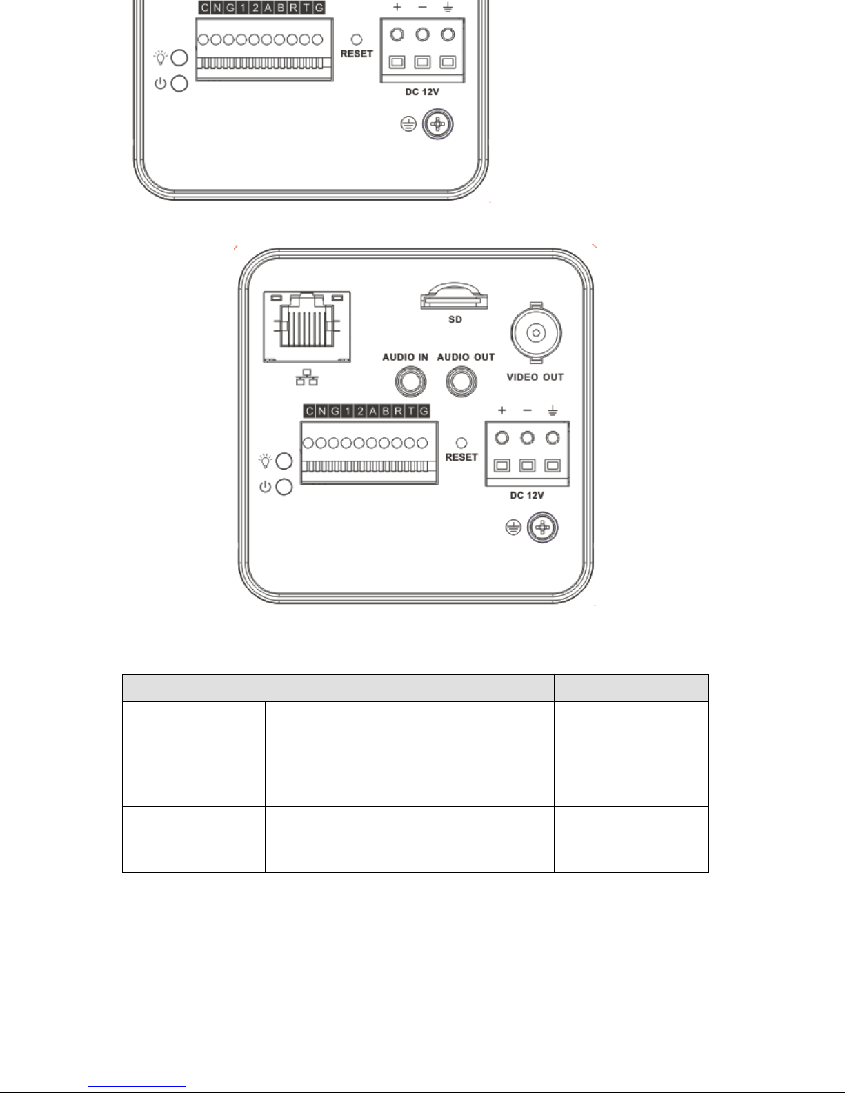
2.1 Rear Panel
The rear panel is shown as below. See
Figure 2-1.
Figure 2-1
Please refer to the following sheet for detail information.
Interface Name
Connector
Function
VIDEO OUT
Video output port
BNC
Output analog video
signal. Can connect to
TV monitor to view
video.
DC 12V
Power port
Power port.
Input DC12V
Page 9

3
STATUS
Indicator Light
Camera working status
indictor light.
System boot up-
red light is on
System upgrades-
red light flashes
System resets-red
light flashes.
C
1-channel alarm
output port
Alarm output port. To
output alarm signal to
the alarm device.
C: Alarm output
public end.
N: Normal open
alarm output end.
N
G
GND
Alarm input ground
end.
1
Alarm input port 1
Alarm input port 1.
Receive on-off signal
from the external alarm
source.
2
Alarm input port 2
Alarm input port 2.
Receive on-off signal
from the external alarm
source.
A
RS485 port
RS485_A port, control
peripheral device and
etc.
B
RS485_B port, control
peripheral device and
etc.
R
RS232 port
RS232_RX,RS232
receive end.
T
RS232_TX,RS232
Page 10

4
COM send out end.
G
GND
RS232 ground end
RESET
RESET button
Restore factory
default setup.
When system is
running normally
(indicator light is
green), press the
RESET button for
at least 5
seconds, system
can restore factory
default setup.
AUDIO OUT
Audio output port
Audio output 3.5mm
JACK port.
Output audio signal to
the passive device
such as earphone.
AUDIO IN
Audio input port
Audio input 3.5mm
JACK port.
Input audio signal from
devices such as pickup.
LAN
Network port
Ethernet port
Connect to standard
Ethernet cable.
SD
SD card port
Connect to SD card.
Note
When you install
the SD card,
please make sure
current card is not
in write mode and
then you can
install it to the
camera.
When you remove
the SD card,
please make sure
current card is not
Page 11

5
in write mode.
Otherwise it may
result in data loss
or card damage.
Before hot swap,
please stop record
operation.
GND
Please make sure the
device is securely
earthed to prevent the
thunderstorm strike.
2.2 Side Panel
Please refer to the following interface for side panel dimension information. The unit is mm.
See Figure 2-2.
Figure 2-2
2.3 Front Panel
Please refer to the following interface for the front panel information. The unit is mm. See
Figure 2-3.
Page 12

6
Figure 2-3
Page 13

7
3 Installation
3.1 Pedestal
Please refer to the steps listed below to install the pedestal. See Figure 3-1 and Figure 3-2.
a) Take the connection adapter and four screws from the accessories bag, line up the
connection adapter to the four holes at the bottom of the camera and then sue the
crosshead screwdriver to fix the four screws firmly.
b) Use M6 screws to secure the camera to the housing or bracket.
Figure 3-1
Figure 3-2
3.2 SD Card
3.2.1 General Series
Please refer to the steps listed below to install/remove the SD card.
Installation
Put the SD card to the SD card slot. You can hear a clear sound when the SD is secure firmly.
Otherwise, system pops up the card. See Figure 3-3.
Remove
Page 14

8
a) Press the rear end of the SD card, system can pop up the SD card.
b) Take the SD card out. See and Figure 3-4.
Figure 3-3
Figure 3-4
3.2.2 Special Series
Important
Please note, the following operation is for professional engineer only. We are not liable
for any problem resulting from the unauthorized operation.
a) Refer to Figure 3-5 to remove the screws.
Page 15

9
Figure 3-5
b) Refer to Figure 3-6.to open the cover.
Figure 3-6
c) Take or remove SD card. See Figure 3-7.
Page 16

10
Figure 3-7
d) Follow the reverse sequence to uninstall/install the screws and covers.
3.3 Bidirectional Talk
Please refer to the steps listed below to connect. See Figure 3-8.
a) Connect the microphone to the audio input port at the rear panel of the camera.
b) Connect the earphone to the audio output port at the rear panel of the camera.
Figure 3-8
3.4 I/O Port
Install Cable
Please follow the steps listed below to install the cable. See Figure 3-9.
Use the small slotted screwdriver to press the corresponding button of cable groove. Insert the
cable into the groove and then release the screwdriver.
Remove Cable
Please follow the steps listed below to remove the cable.
Use the small slotted screwdriver to press the corresponding button of cable groove. Remove
the cable out of the groove and then release the screwdriver.
Page 17

11
Figure 3-9
3.5 Lens Protection Film
Note
Before you use the camera, please remove the lens protection film to guarantee video
quality.
Please refer to Figure 3-10 to remove the lens protection film.
Figure 3-10
Page 18

12
4 Quick Configuration Tool
4.1 Overview
Quick configuration tool can search current IP address, modify IP address. At the same time,
you can use it to upgrade the device.
Please note the tool only applies to the IP addresses in the same segment.
4.2 Operation
Double click the “ConfigTools.exe”icon, you can see an interface is shown as in Figure 4-1.
In the device list interface, you can view device IP address, port number, subnet mask, default
gateway, MAC address and etc.
Figure 4-1
Select one IP address and then right click mouse, you can see an interface is shown as in
Figure 4-2.
Note:
You can set the IP address, subnet mask and gateway for the block camera and PC. Please
note block camera IP address and PC IP address shall be in the same network segment if
there is no router. Block camera default IP address is 192.168.1.108. If there is a router,
please set the corresponding gateway and subnet mask.
The factory default user name is admin and password is admin. For security reasons, please
modify your password after you first login.
For detailed WEB operation, please refer to the block camera Web Operation Manual in the
resource CD.
Page 19

13
Figure 4-2
Select the “Open Device Web” item; you can go to the corresponding web login interface. See
Figure 4-3.
Figure 4-3
If you want to modify the device IP address without logging in the device web interface, you
can go to the configuration tool main interface to set.
In the configuration tool search interface (Figure 4-1), please select a device IP address and
then double click it to open the login interface. Or you can select an IP address and then click
the Login button to go to the login interface. See Figure 4-4.
In Figure 4-4, you can view device IP address, user name, password and port. Please modify
the corresponding information to login.
Please note the port information here shall be identical with the port value you set in TCP port
in Web Network interface. Otherwise, you can not login the device.
If you are using device background upgrade port 3800 to login, other setups are all invalid.
Page 20

14
Figure 4-4
After you logged in, the configuration tool main interface is shown as below. See Figure 4-5.
Figure 4-5
For detailed information and operation instruction of the quick configuration tool,
please refer to the Quick Configuration Tool User’s Manual included in the resources
CD.
Page 21

15
5 Web Operation
These series block camera products support the Web access and management via PC.
Web includes six modules: encode setup bar, window adjust bar, system menu bar, window
function option bar, PTZ control bar, PTZ setup/menu.
5.1 Network Connection
Please follow the steps listed below for network connection.
Make sure the block camera has connected to the network properly.
Please set the IP address, subnet mask and gateway of the PC and the block camera
respectively. (Please set the same segment for the device and PC if there is no router.
Please set gateway and subnet mask if there is a router in the network. ).Device default IP
address is 192.168.1.108.
Use order ping ***.***.***.***(* block camera address) to check connection is OK or not.
5.2 Login and Logout
Open IE and input block camera address in the address bar.
For example, if your camera IP is 192.168.1.108, then please input http:// 192.168.1.108 in IE
address bar. See Figure 5-1.
Figure 5-1
The login interface is shown as below. See Figure 5-2.
Please input your user name and password.
Default factory name is admin and password is admin.
Note: For security reasons, please modify your password after you first login.
Input your IP
address here
Page 22

16
Figure 5-2
If it is your first time to login in, system pops up warning information to ask you whether install
control webrec.cab or not after you logged in for one minute. Please click OK button, system
can automatically install the control. When system is upgrading, it can overwrite the previous
Web too.
If you can’t download the ActiveX file, please check whether you have installed the plug-in to
disable the control download. Or you can lower the IE security level. See Figure 5-3.
Figure 5-3
After you logged in, you can see the main window. See Figure 5-4.
Page 23

17
Figure 5-4
Please refer to the Web Operation Manual included in the resource CD for detailed operation
instruction.
Page 24

18
6 FAQ
Bug
I can not boot up
the device or can
not control the
device.
Please click RESET button for at least five seconds to restore
factory default setup.
Audio function
Please use active device for the audio monitor input, otherwise there
is no audio in the client-end.
SD card hot swap
Before draw out SD card, please stop record or snapshot first and
then wait for at least 15 seconds to remove the SD card. All the
operations before is to maintain data integrity. Otherwise you can
lose all the data in the SD card!
SD card write
times
Do not set the SD card as the storage media to storage the
schedule record file. It may damage the SD card duration.
I can not use the
disk as the storage
media.
When disk information is shown as hibernation or capacity is 0,
please format it first (Via Web).
Page 25

19
Appendix Toxic or Hazardous Materials or Elements
Component
Name
Toxic or Hazardous Materials or Elements
Pb
Hg
Cd
Cr VI
PBB
PBDE
Sheet Metal
○ ○ ○ ○ ○ ○
Casting fitting
○ ○ ○ ○ ○ ○
PCB
○ ○ ○ ○ ○
○
Camera Driver
○ ○ ○ ○ ○ ○
Connection
Cable
○ ○ ○ ○ ○ ○
Power
(If possible)
○ ○ ○ ○ ○
○
Bracket
(If possible)
○ ○ ○ ○ ○ ○
Accessories
○ ○ ○ ○ ○ ○
O: Indicates that the concentration of the hazardous substance in all homogeneous materials
in the parts is below the relevant threshold of the SJ/T11363-2006 standard.
X: Indicates that the concentration of the hazardous substance of at least one of all
homogeneous materials in the parts is above the relevant threshold of the SJ/T11363-2006
standard. During the environmental-friendly use period (EFUP) period, the toxic or hazardous
substance or elements contained in products will not leak or mutate so that the use of these
(substances or elements) will not result in any severe environmental pollution, any bodily injury
or damage to any assets. The consumer is not authorized to process such kind of substances
or elements, please return to the corresponding local authorities to process according to your
local government statutes.
Note
This user’s manual is for reference only. Slight difference may be found in user
interface.
All the designs and software here are subject to change without prior written notice.
All trademarks and registered trademarks mentioned are the properties of their
respective owners.
If there is any uncertainty or controversy, please refer to the final explanation of us.
Please visit our website for more information.
 Loading...