

Page 1

HDCVI Camera User’s Manual
Version 1. 0.0
Page 2

i
Table of Contents
1 General Introduction ....................................................................................................................... 1
1.1 Overview ............................................................................................................................. 1
1.2 Features.............................................................................................................................. 1
2 Device Framework .......................................................................................................................... 2
3 Installation ......................................................................................................................................... 5
Model A ............................................................................................................................................ 5
Model B1 and B2............................................................................................................................ 6
Model C ............................................................................................................................................ 7
Model D ............................................................................................................................................ 8
Model E ............................................................................................................................................ 9
Model F........................................................................................................................................... 10
4 Menu ................................................................................................................................................ 12
4.1 HCVR Settings ................................................................................................................ 12
4.2 Menu Operation .............................................................................................................. 12
4.3 Set Audio Coax ............................................................................................................... 13
Page 3

ii
Welcome
Thank you for purchasing our HDCVI camera!
This user’s manual is designed to be a reference tool for your system.
Please read the following safeguard and warnings carefully before you use this series product!
Please keep this user’s manual well for future reference!
Important Safeguards and Warnings
1. Electrical safety
All installation and operation here should conform to your local electrical safety codes.
The power shall conform to the requirement in the SELV (Safety Extra Low Voltage) and the
Limited power source is rated DC 12V or AC24V in the IEC60950-1. (Power supply requirement is
subject to the device label).
Please install easy-to-use device for power off before installing wiring, which is for emergent power
off when necessary.
Please check if the power supply meets the requirements of working voltage of the camera before
operating the device (The material and length of the power supply cable will influence terminal
voltage value).
Please prevent the line cord from being trampled or pressed, especially the plug, power socket and
the junction from the device.
2. Environment
Please don’t aim the device at strong light (such as lighting, sunlight and so on) to focus.
Please transport, use and store the device within the range of allowed humidity and temperature.
Please do not allow water and other liquid falling into the camera in case that the internal
components are damaged.
Please keep the sound ventilation in case of heat accumulation.
Heavy stress, violent vibration or water splash are not allowed during transportation, storage and
installation.
Please pack the device with standard factory packaging or material with same quality when
transporting the device.
It is recommended to use the device together with lightning protection device to enhance lightning
protection effect.
It is recommended to GND the device to enhance device reliability.
It is advised to use qualified video transmission cable to improve video quality. It is recommended
to use 75-3 coaxial cable or higher standard.
3. Warning
Please use the standard accessories provided by manufacturer and make sure the device is
installed and fixed by professional engineers.
Please prevent the device surface from the radiation of laser beam when using laser beam device.
Please do not provide two or more power supply modes for the device, otherwise it may cause
Page 4

iii
damage to the device.
Any device is not supported to be connected between the camera and PoC XVR when the camera
is in the condition of PoC power supply, including UTC, Balun, optical transceiver, distributor and
convertor etc. Otherwise it may burn the connected device.
PoC supply voltage is up to 48V. Therefore please do not dismantle the device during normal
operation; otherwise it may cause danger to both device and users due to high voltage.
Statement
Please refer to the actual product for more details; the manual is just for reference.
The manual will be regularly upgraded according to the product update; the upgraded content will
be added in the manual without prior announcement.
Please contact the supplier or customer service if there is any problem occurred when using the
device.
Please contact the customer service for the latest procedure and supplementary documentation.
There may be deviation between the actual value of some data and the value provided in the
manual due to the reasons such as the real environment is not stable and so on. Please refer to
the company’s final explanation if there is any doubt or dispute.
The company is not liable for any loss caused by the operation which is not followed by the manual.
Page 5

1
1 General Introduction
1.1 Overview
This series HDCVI camera conforms to the HDCVI standard. It supports video signal highspeed long distance transmission without any delay. It can be controlled by the HCVR
conforming to the HDCVI.
1.2 Features
High-performance CMOS image sensor, megapixel definition.
Support HD video, control signal coaxial transmission.
For 720P series, support RG59 coaxial cable transmission without any loss. The distance
is over 800m. For 1080P, 4M series, support RG59 coaxial cable transmission without any
loss. The distance is over 500m. PoC power supply supports transmission distance up to
400m for 1080P and 300m for 4MP via RG59.
Support HDCVI HD/SD output.
Support ICR switch to realize surveillance both in the daytime and at night.
Support OSD menu adjustment parameters.
Support smart IR function.
Support DWDR function.
Support High speed, long distance real-time transmission.
Support DC12V/PoC (Power over Coax) power supplying.
Support IP67 compliance (Model D doesn’t support IP67).
It can be applied to the various scenes such as store, supermarket, coffee shop, school,
hotel, office, restaurant, garden, parking lot and etc.
Page 6

2
2 Device Framework
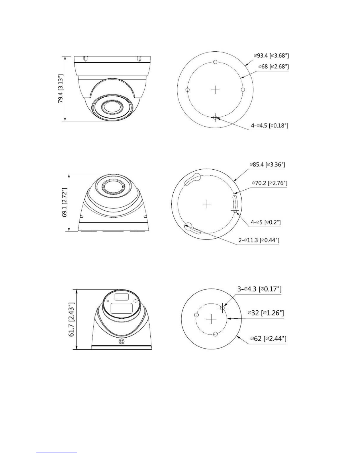
See Figure 2-1 for the dimension of model A.
Figure 2-1
See Figure 2-2 and Figure 2-3 for the dimension of model B1 and model B2.
Figure 2-2
Figure 2-3
Page 7
3
See Figure 2-4 for the dimension of model C.
Figure 2-4
See Figure 2-5 for the dimension of model D.
Figure 2-5
See Figure 2-6 for the dimension of model E.
Figure 2-6
See Figure 2-7 for the dimension of model F.
Page 8

4
Figure 2-7
The device ports include one DC12V power input port and one BNC video output port.
Please refer to Figure 2-8 for DC12V power input port.
Figure 2-8
Please refer to Figure 2-9 for video output port.
Figure 2-9
Note
Video output port outputs HDCVI HD video by default. HD/SD output can be switched via
UTC Controller or OSD menu →Advanced →Video Output.
For PoC models, the port can realize both power input via coax and video output at the
same time during PoC power supply. PoC can be supported only in the HDCVI video
output mode.
Warning
Any device is not supported to be connected between the camera and PoC XVR when the
camera is in the condition of PoC power supply, including UTC, Balun, optical transceiver,
distributor and convertor etc. Otherwise it may burn the connected device.
Please do not dismantle the device during normal operation; otherwise it may cause
danger to both device and users due to high voltage.
Page 9

5
3 Installation
Important
Before the installation, please make sure the installation surface can sustain at
least 3X weight of the bracket and the camera.
Model A
Figure 3-1
Step 1
Hold the decoration ring tightly and unscrew the pedestal anticlockwise.
Step 2
Confirm the installation location and dig holes on the installation surface.
Step 3
Use tools to insert expansion bolts into the installation holes and fix them firmly.
Step 4
Adjust pedestal location (if it is side cable outlet, then pull the cable through the side outlet
cable slot). Align the bolt fixing holes of the device pedestal with the expansion bolt fixing holes
of the installation surface; insert the self-tapping screws into the expansion bolts and fasten
them firmly to fix the pedestal on the installation surface (if it is top outlet, pull the cable
through the outlet hole on the installation surface after the pedestal is fixed firmly).
Step 5
Rotate the decoration ring and fix it slightly, rotate the enclosure and dome body to a proper
monitoring location; connect the video output port of device cable to back-end encoding device,
and connect power port to power; adjust lens focal length and make image clear by adjusting
the zoom/focus screws using screwdriver after the image is displayed on the back-end coding
device; finally rotate the decoration ring firmly.
Page 10

6
So far the device installation and cable connection are completed; you can check the image
via back-end coding device.
Note
1) Please use wide slotted screwdriver to avoid damaging screws during focus and zoom;
2) It is not allowed to twist screw violently when ZOOM is adjusted to W or T.
Please refer to Figure 3-2 for focusing operation
Figure 3-2
Please pay attention to the following points during focusing operation.
1. Zoom end is at W end by default when the product is delivered from factory, it has to adjust
clockwise when adjusting Zoom end for the first time.
2. It has to twist slowly when adjusting Focus end, you need to check the image definition
when twisting Focus end. It will encounter obvious resistance when it comes to the
limitation end if it misses the location of best definition during adjustment, at this moment,
please stop twisting Focus end.
3. It needs to select a proper slotted screwdriver when adjusting Zoom and Focus. It is
recommended that the size of screwdriver head should be 3.5*0.7mm (width*depth).
Please be aware to insert the screwdriver head to the bottom of focusing slot and then
begin to adjust.
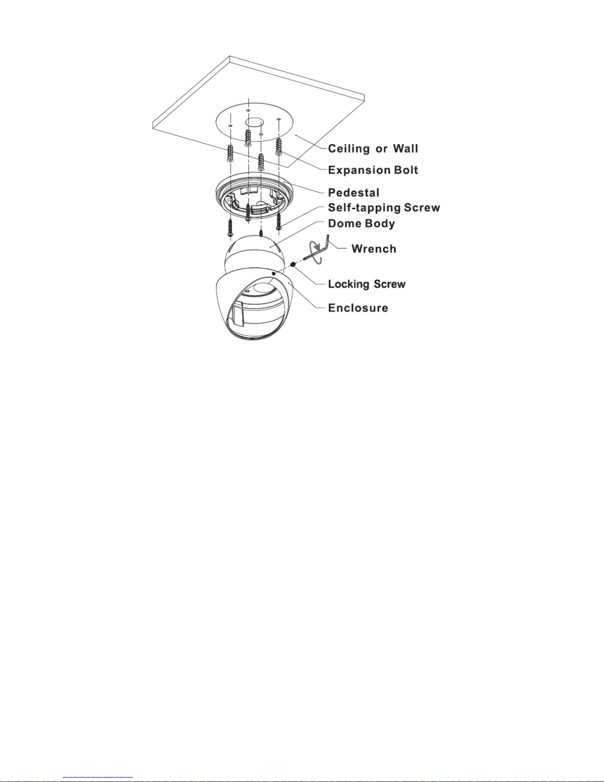
Model B1 and B2
Page 11
7
Figure 3-3
Step 1
Loosen locking screws anticlockwise and remove the pedestal.
Step 2
Confirm the installation location and dig holes on the installation surface.
Step 3
Use tools to insert expansion bolts into the installation holes and fix them firmly.
Step 4
Adjust pedestal location (if it is side cable outlet, then pull the cable through the side outlet
cable slot). Align the bolt fixing holes of the device pedestal with the expansion bolt fixing holes
of the installation surface; insert the self-tapping screws into the expansion bolts and fasten
them firmly to fix the pedestal on the installation surface (if it is top outlet, pull the cable
through the outlet hole on the installation surface after the pedestal is fixed firmly).
Step 5
Put the enclosure and dome body into the pedestal, insert locking screws clockwise and fix
them slightly; rotate enclosure and dome body to a proper monitoring location; finally fasten
the locking screws firmly.
So far the device installation and cable connection are completed; you can check the
monitoring image via back-end coding device.
Model C
Page 12

8
Figure 3-4
Step 1
Hold the decoration ring tightly and unscrew the pedestal anticlockwise.
Step 2
Confirm the installation location and dig holes on the installation surface.
Step 3
Use tools to insert expansion bolts into the installation holes and fix them firmly.
Step 4
Adjust pedestal location (if it is side cable outlet, then pull the cable through the side outlet
cable slot). Align the bolt fixing holes of the device pedestal with the expansion bolt fixing holes
of the installation surface; insert the self-tapping screws into the expansion bolts and fasten
them firmly to fix the pedestal on the installation surface (if it is top outlet, pull the cable
through the outlet hole on the installation surface after the pedestal is fixed firmly).
Step 5
Rotate the decoration ring and fix it slightly, rotate the compression cover and dome body to a
proper monitoring location; finally rotate the decoration ring firmly.
So far the device installation and cable connection are completed; you can check the image
via back-end coding device.
Model D
Page 13

9
Figure 3-5
Step 1
Rotate the enclosure to align the arrow on the enclosure edge with the arrow on the pedestal
edge; press inward according to the arrow location of the enclosure and meanwhile push
outward according to the arrow location of the pedestal to separate the concave; pull the
enclosure to make it break away from the pedestal.
Step 2
Confirm the installation location and dig holes on the installation surface.
Step 3
Use tools to insert expansion bolts into the installation holes and fix them firmly.
Step 4
Adjust pedestal location (if it is side cable outlet, then pull the cable through the side outlet
cable slot). Align the bolt fixing holes of the device pedestal with the expansion bolt fixing holes
of the installation surface; insert the self-tapping screws into the expansion bolts and fasten
them firmly to fix the pedestal on the installation surface (if it is top outlet, pull the cable
through the outlet hole on the installation surface after the pedestal is fixed firmly).
Step 5
Make the enclosure buckle get stuck into the pedestal, rotate the enclosure and dome body to
a proper monitoring location.
So far the device installation and cable connection are completed; you can check the image
via back-end coding device.
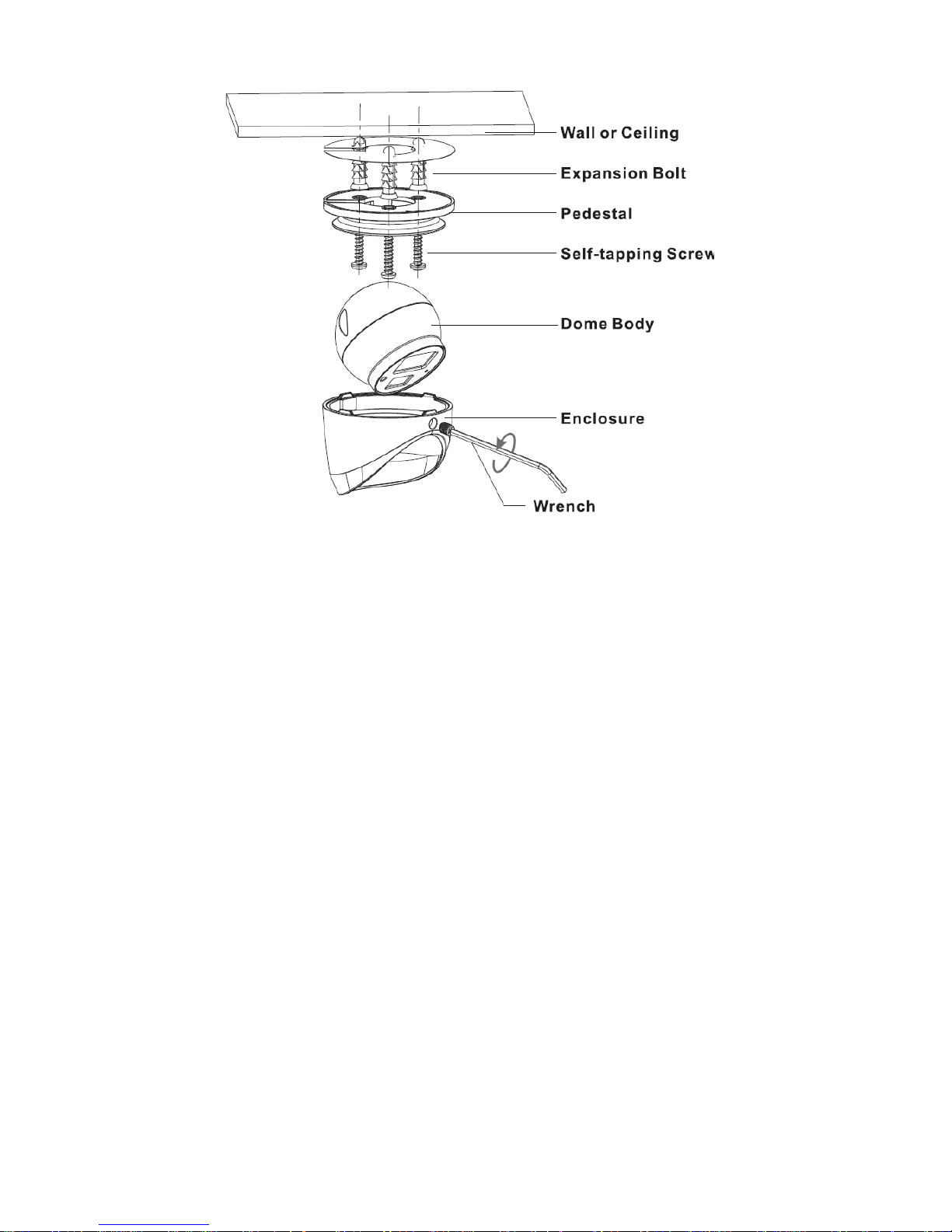
Model E
Page 14
10
Figure 3-6
Step 1
Loosen locking screws anticlockwise and remove the pedestal.
Step 2
Confirm the installation location and dig holes on the installation surface.
Step 3
Use tools to insert expansion bolts into the installation holes and fix them firmly.
Step 4
Adjust pedestal location (if it is side cable outlet, then pull the cable through the side outlet
cable slot). Align the bolt fixing holes of the device pedestal with the expansion bolt fixing holes
of the installation surface; insert the self-tapping screws into the expansion bolts and fasten
them firmly to fix the pedestal on the installation surface (if it is top outlet, pull the cable
through the outlet hole on the installation surface after the pedestal is fixed firmly).
Step 5
Put the enclosure and dome body into the pedestal, insert locking screws clockwise and fix
them slightly; rotate enclosure and dome body to a proper monitoring location; finally fasten
the locking screws firmly.
So far the device installation and cable connection are completed; you can check the
monitoring image via back-end coding device.
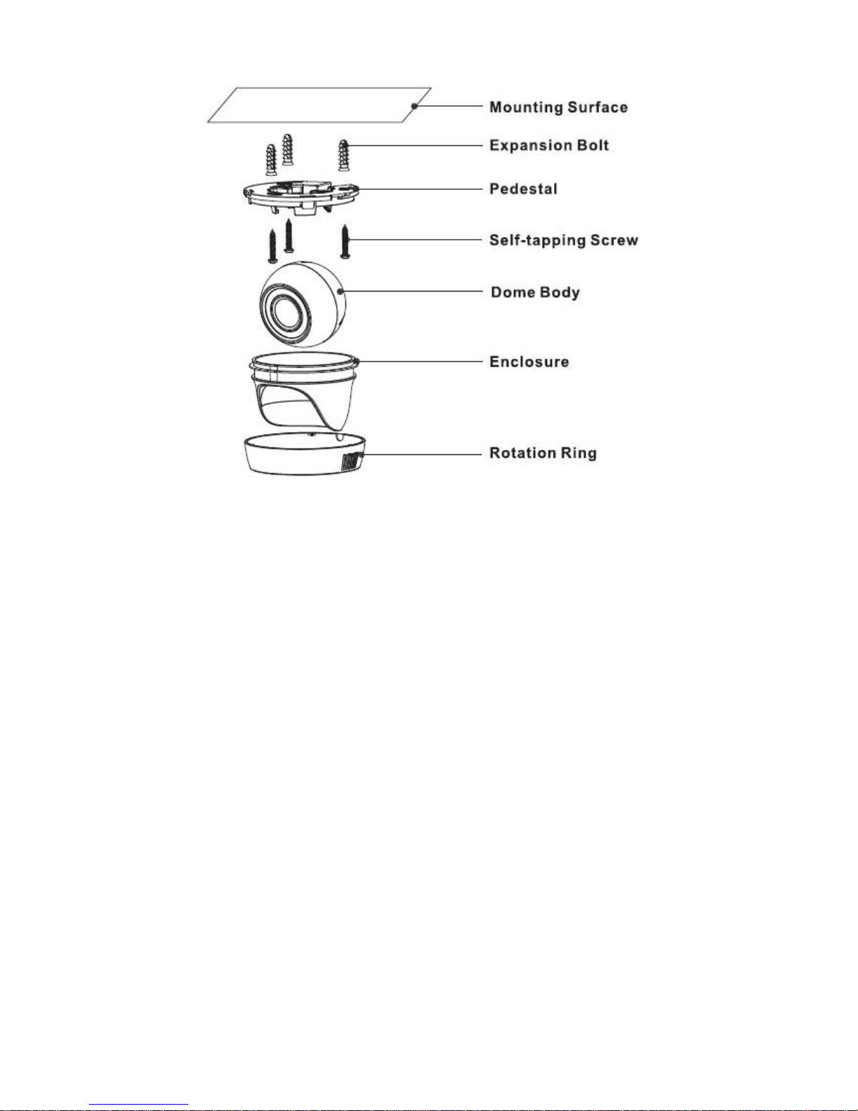
Model F
Page 15
11
Figure 3-7
Step 1
Use expansion bolts to fix the pedestal on the mounting surface.
Step 2
Align the dome body with the location of U-shaped groove, and lay the dome body into the
enclosure; buckle the enclosure on the device pedestal.
Step 3
Install the rotation ring after the enclosure is fixed on the pedestal together with the dome body;
make sure the location of pedestal cable exit hole is in accordance with that of the rotation ring.
Step 4
Rotate the dome body to proper monitoring angle.
So far the device installation and cable connection are completed; you can check the image
via back-end coding device.
Page 16

12
4 Menu
4.1 HCVR Settings
This HDCVI camera series can adjust OSD menu via coaxial control. After connected the
camera to the HDCVI series HCVR, from Main Menu->Setting->System->PTZ, you need to
select the channel number for access and set control mode as HDCVI and the protocol as HDCVI. Click “Save” button to save current setup. See Figure 4-1.
Figure 4-1
4.2 Menu Operation
Click the right mouse button and select “PTZ Control”, then you will see the “PTZ Setup” menu,
which is as shown in Figure 4-2 and Figure 4-3.
Figure 4-2
Page 17

13
Figure 4-3
See Sheet 4-1 for the details of button functions.
Button
Function
Open menu
、
Select menu item
、
Select menu value
Sheet 4-1
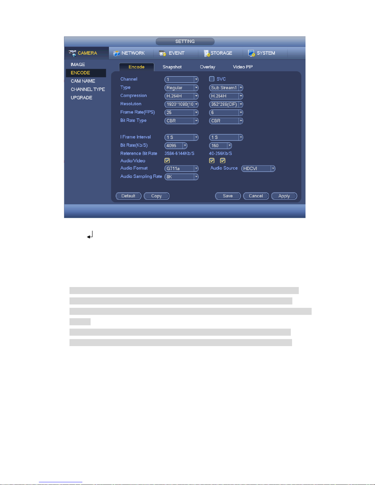
4.3 Set Audio Coax
From “Main Menu > Setting > Camera > Encode > Encode”, you need to set “Audio Format” as
“G711a” and the “Audio Source” as “HDCVI”. See Figure 4-4 for more details.
Page 18
14
Figure 4-4
If there is “ ”, click the “Confirm” button in “Menu Operation” interface to go to the 2nd menu.
Click “Return” button to go back to the previous menu interface.
Please use an UTC controller or enter the OSD menu for to switchover between HD & SD
video output.
Note
This manual is for reference only. Slight difference may be found in the user interface.
All the designs and software here are subject to change without prior written notice.
All trademarks and registered trademarks mentioned are the properties of their respective
owners.
If there is any uncertainty or controversy, please refer to the final explanation of us.
Please visit our website or contact your local service engineer for more information.
 Loading...