

Page 1

Network Video Alarm Controller
Quick Start Guide
Version 1.0.0
Page 2

i
Table of Contents
1 FEATURES AND SPECIFICATIONS ...............................................................................1
1.1 Overview ....................................................................................................................1
1.2 Features .....................................................................................................................1
1.3 System Composition ................................................................................................1
2 INSTALLATION ....................................................................................................................3
2.1 ARC5408B Series ....................................................................................................3
2.2 ARC5408C Series ....................................................................................................5
2.3 Wiring....................................................................................................................... 10
3 WEB Login and Logout .................................................................................................... 14
3.1 Login ........................................................................................................................ 14
3.2 Logout...................................................................................................................... 14
4 Arm/Disarm ........................................................................................................................ 15
4.1 Arm/Disarm ............................................................................................................. 15
4.2 Add and Delete Wireless Device......................................................................... 18
4.3 Zone Config ............................................................................................................ 19
4.4 Emergency Alarm Config ..................................................................................... 22
4.5 Siren and Alarm Output Config ........................................................................... 23
4.6 Failure Config ......................................................................................................... 25
4.7 Video Alarm Config ............................................................................................... 27
4.8 Event Report Config .............................................................................................. 29
4.9 Event Info View ...................................................................................................... 31
4.10 Network Config .................................................................................................... 31
5 Wireless Alarm Programming Keypad Operation ........................................................ 35
5.1 Key ........................................................................................................................... 35
5.2 Wireless Match Code ............................................................................................ 36
5.3 Before Operation ................................................................................................... 36
5.4 Arm........................................................................................................................... 39
5.5 Disarm ..................................................................................................................... 39
5.6 Bypass Isolation ..................................................................................................... 39
5.7 Zone Setup ............................................................................................................. 40
5.8 Other Setup ............................................................................................................ 41
5.9 COM Setup ............................................................................................................. 42
5.10 Output Setup ........................................................................................................ 43
5.11 View System Status ............................................................................................ 44
Appendix 1Contact ID Event Code.................................................................................... 47
Page 3

ii
Welcome
Thank you for purchasing our network video alarm controller!
This quick start guide will help you become familiar with our network video alarm controller in a
very short time.
Before installation and operation, please read the following safeguard and warning carefully!
Model
ARC5408B and ARC5408C
Page 4

iii
Important Safeguard and Warning
1.Electrical safety
All installation and operation here should conform to your local electrical safety codes.
The product must be grounded to reduce the risk of electric shock.
We assume no liability or responsibility for all the fires or electric shock caused by improper
handling or installation.
2.Transportation security
Heavy stress, violent vibration or water splash are not allowed during transportation, storage and
installation.
3.Installation
Keep upwards. Handle with care.
Do not apply power to the alarm controller before completing installation.
Do not place objects on the alarm controller.
4.Qualified engineers needed
All the examination and repair work should be done by the qualified service engineers.
We are not liable for any problems caused by unauthorized modifications or attempted repair.
5.Environment
The alarm controller should be installed in a cool, dry place away from direct sunlight,
inflammable, explosive substances and etc.
This series product shall be transported, storage and used in the environment ranging from -10℃
to 55 ℃.
6. Accessories
Be sure to use all the accessories recommended by manufacturer.
Before installation, please open the package and check all the components are included.
Contact your local retailer ASAP if something is broken in your package.
Before Start
About Alarm System
For the alarm system consists of the network alarm controller, though it has stable and reliable
performance, it may become null in the following situations:
The protection zone the intruder entering has not enabled the arm function or the intruder
has enough knowledge to disable the system.
The siren device installation position is not right; it does not have the warning function.
The detector is null when there is an alarm outage and etc.
The detector is not in the proper position and can not detect the corresponding zone.
System can not generate an alarm when there is something wrong with the alarm signal
transmission system (the service is disabled, there is malicious attack and etc).
Page 5

iv
The device is null resulting from non-schedule maintenance of the alarm system.
About Installation Notice
The installation engineers are recommended to check the system regularly such as once a
month. It is to guarantee system long-term stable operation.
The installation engineers are recommended to test the system regularly such as once a
week.
Please arrange some training classes for the end-user. It is to keep them familiar with the
system.
System Test Notice
After the installation, you can connect to the AC/DC power to test.
You can test the all functions of the alarm controller after you complete all programming
work.
Page 6

1
1 FEATURES AND SPECIFICATIONS
1.1 Overview
This series product integrates on-off alarm input and output, and video processing as one multifunctional video alarm controller. It supports protection zone alarm, wireless remote arm/disarm,
keypad arm/disarm, emergency alarm, video preview authority management, alarm can trigger
pop-up video for you to recheck, video alarm and etc. It can be used in many environments such
as bank, school, store, residential district. It can perfectly work with the alarm and surveillance
solutions when there is an alarm operation and management platform.
1.2 Features
This series product has the following features:
8-ch programming wired zone, 32-ch wireless zone, 1-ch relay control output can extend to
9-ch output.
4-ch 720P analog HDCVI or 4-ch 720P network video input, may achieve alarm video review
and motion, video loss, video tampering intelligent analytic, meantime support video local
storage and playback.
1-ch audio input, 1-ch talk input and A/V reuse, 1-ch audio output and talk output reuse.
8-ch wireless alarm programming keypad or 8-ch wires alarm programming keypad, 16
wireless remote controls, may use keypad, remote control, smart phone APP to arm/disarm.
Set plan to auto complete arm/disarm.
Alarm event support report in SMS (-C/-E/-CW/-EW models)
Main power outage detection and alternate power in place, low battery detection.
Max of 1024 alarm events and failure event records plus 512 system logs.
100 web users, 23 keypad users, 3-level right management: 1 administrator, 1 installer, 21
operator.
1-ch 12V DC 1A AUX output and 2-ch 12V DC/500mA AUX output (1-ch controllable, used
in siren output)
2-ch RS485, 1-ch extension alarm output (i.e. ARM708), 1-ch alarm programming keypad.
1-ch USB and 1-ch 2.5 inch Sata hard disk.
Multiple backup alarm info transmission channel, support PSTN public tel network, TCP/IP
network, 3G network.
2-ch call center, 2-ch network call center (auto registration, static IP).
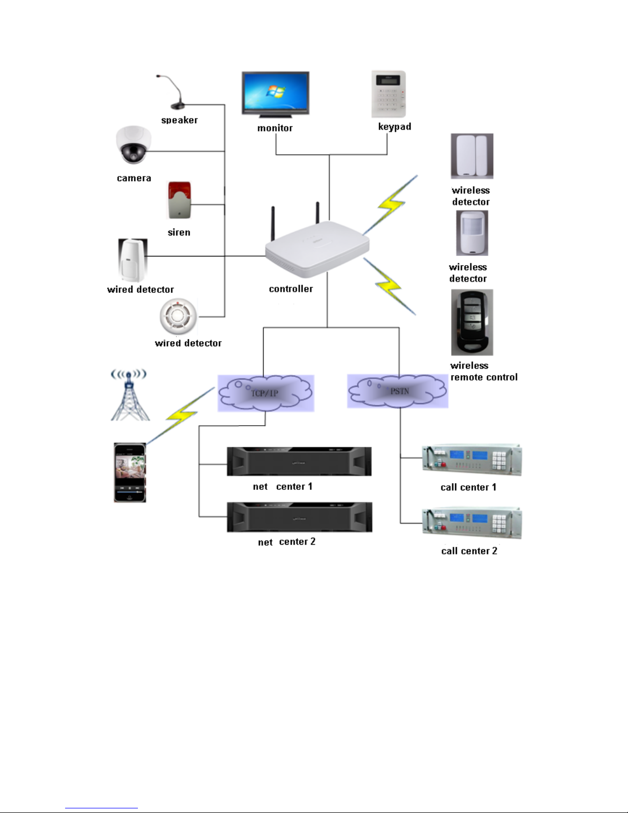
1.3 System Composition
Video Video Alarm Controller and camera, detector, keypad, siren, audio device, PSTN and
monitor, WEB client form a comprehensive linkage alarm system. The system basic connection
figure is in Figure 1- 1.
Page 7
2
Figure 1- 1
Page 8
3
2 INSTALLATION
2.1 ARC5408B Series
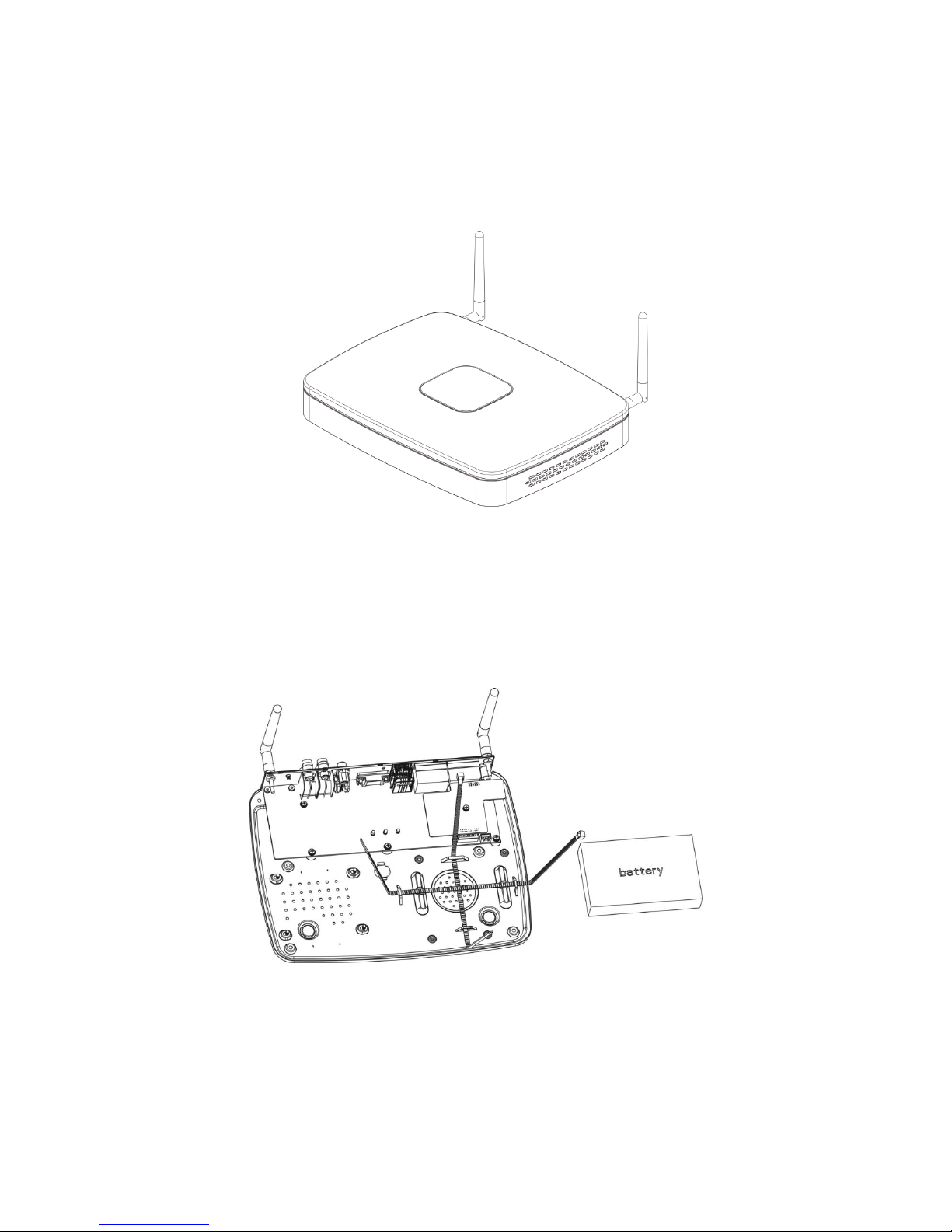
2.1.1 Appearance
Video alarm controller appearance is in Figure 2-1.
Figure 2-1
2.1.2 Battery and HDD Installation
To install battery:
Step 1. Tie the two lines symmetrically and pull through pedestal, see Figure 2-2.
Figure 2-2
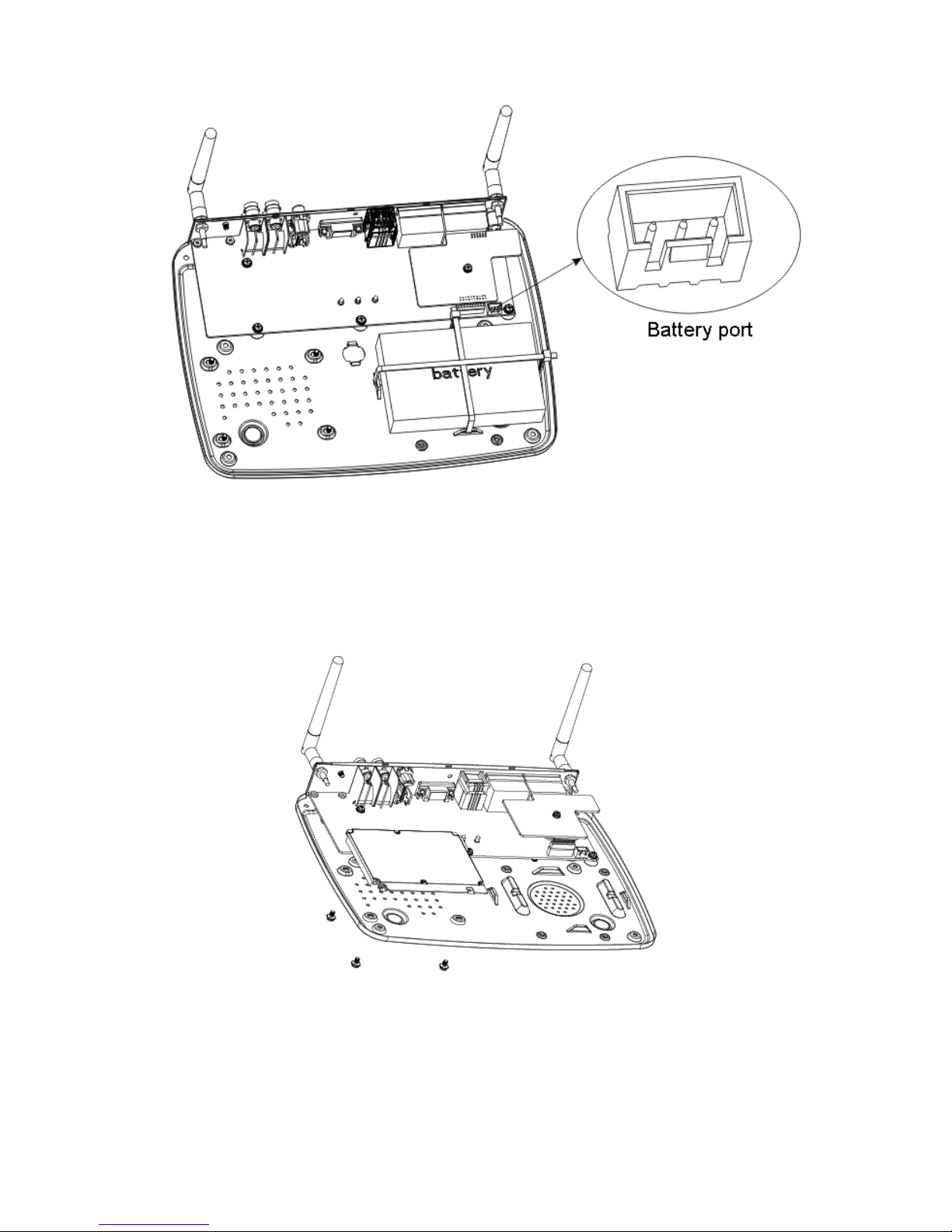
Step 2. Place battery on the tied line.Tie the battery tightly via the lines, cut the extra part of lines.
Step 3. Insert battery and lines into battery port on device, see Figure 2-3.
Page 9
4
Figure 2-3
2.1.3 Install HDD
To install HDD:
Step 1. Please use 2.5 inch HDD, fix it on pedestal with screwdriver.
Step 2. Insert HDD port on motherboard, see Figure 2-4.
Figure 2-4
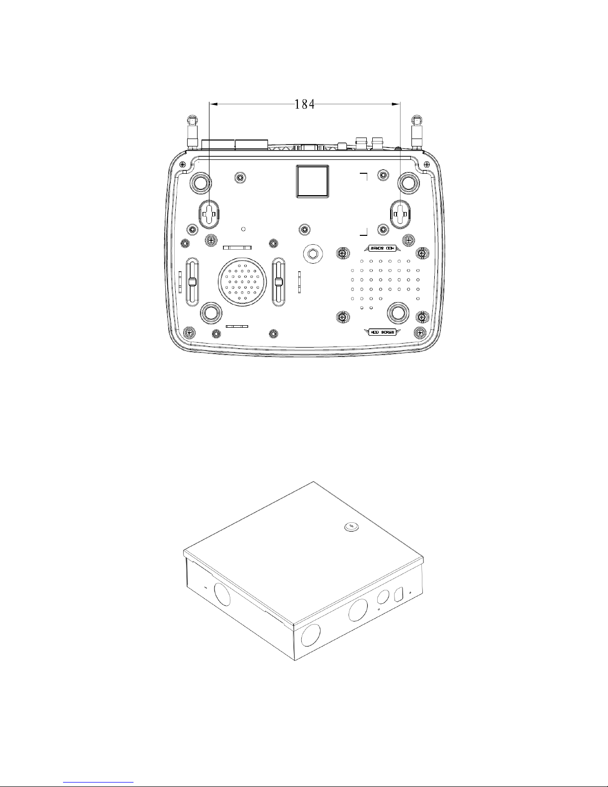
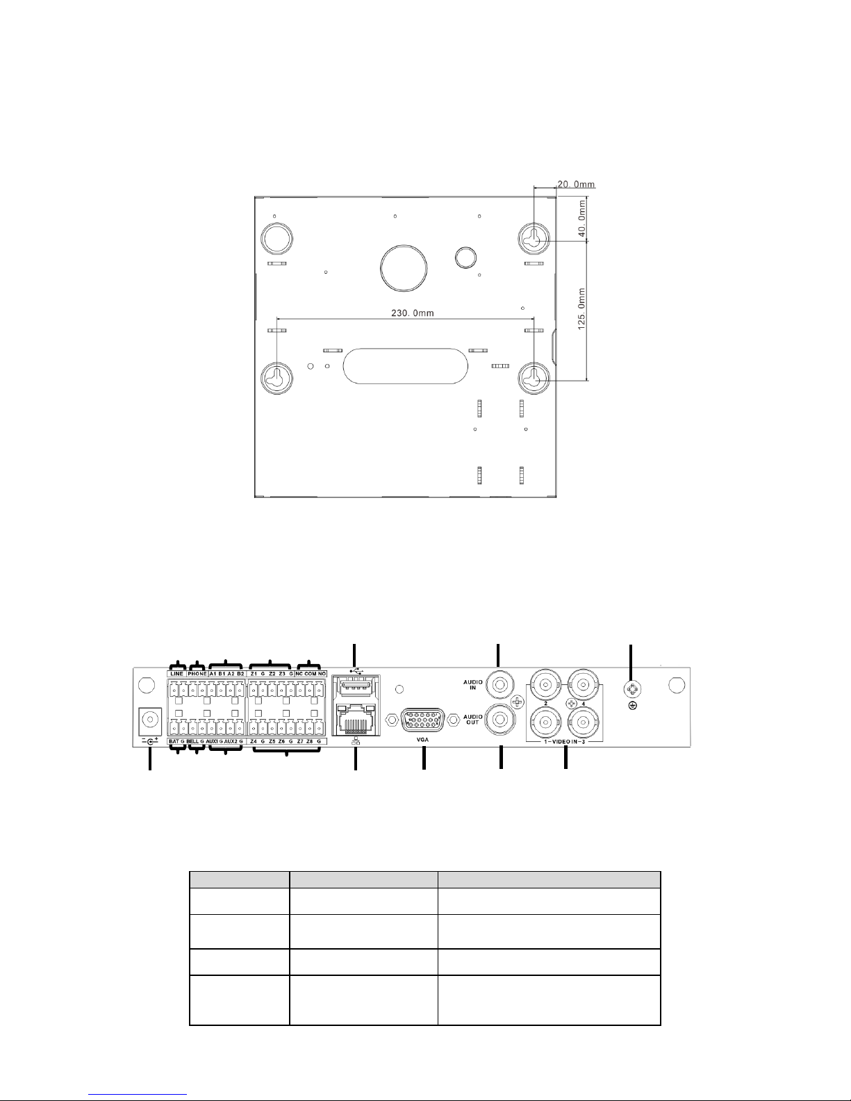
2.1.4 Wall Mount
The device supports wall mount and desktop placement.
To mount on wall:
Step 1. Open device package, take out plastic expansion bolt and self-tapping screw.
Page 10
5
Step 2. Dig two holes on wall with distance of 184mm in between. Insert the plastic expansion
bolt and fasten self-tapping screw.
Step 3. Hand the device on the screw.
Figure 2-5
2.2 ARC5408C Series
2.2.1 Appearance
Video alarm controller appearance is in Figure 2-6.
Figure 2-6
Page 11
6
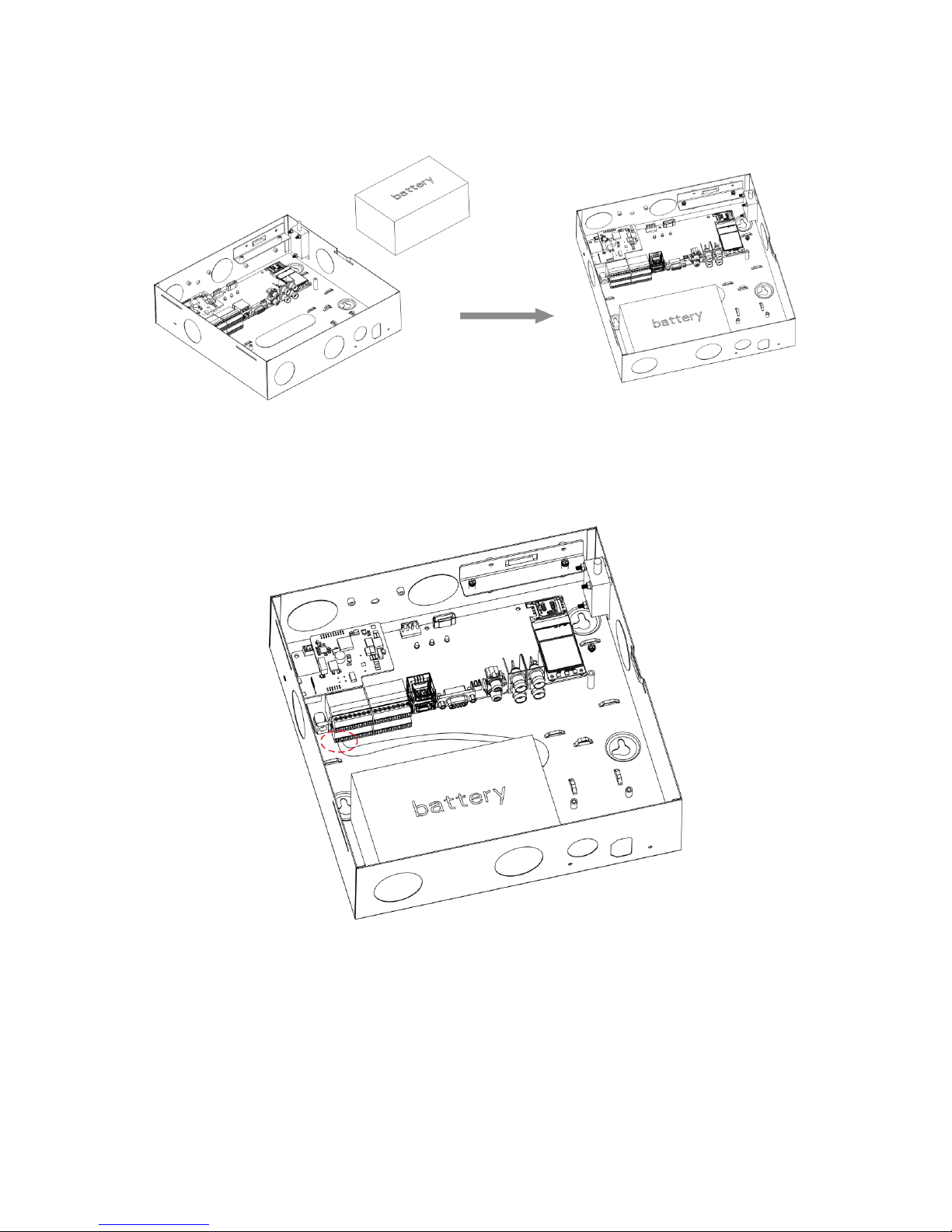
2.2.2 Battery Installation
To install battery:
Step 1. Place battery in the case, position as in Figure 2-7.
Figure 2-7
Step 2. Insert one end of battery line into battery, and insert the other end of battery into external
backup power port, see Figure 2-8.
Figure 2-8
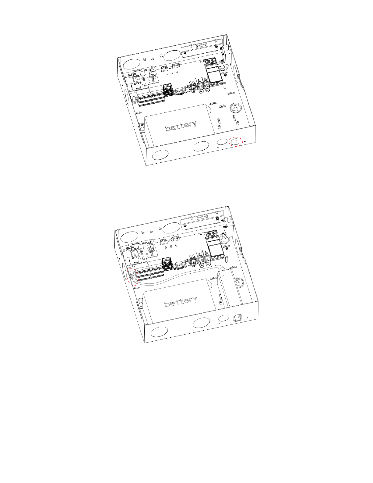
2.2.3 Power Adaptor Installation
Step 1. Refer to Figure 2-9, knock off battery cover.
Page 12
7
Figure 2-9
Step 2. Place power adaptor inside controller, and adaptor port faces power out hole on case.
Insert power line into power port on the controller, see Figure 2-10.
Figure 2-10
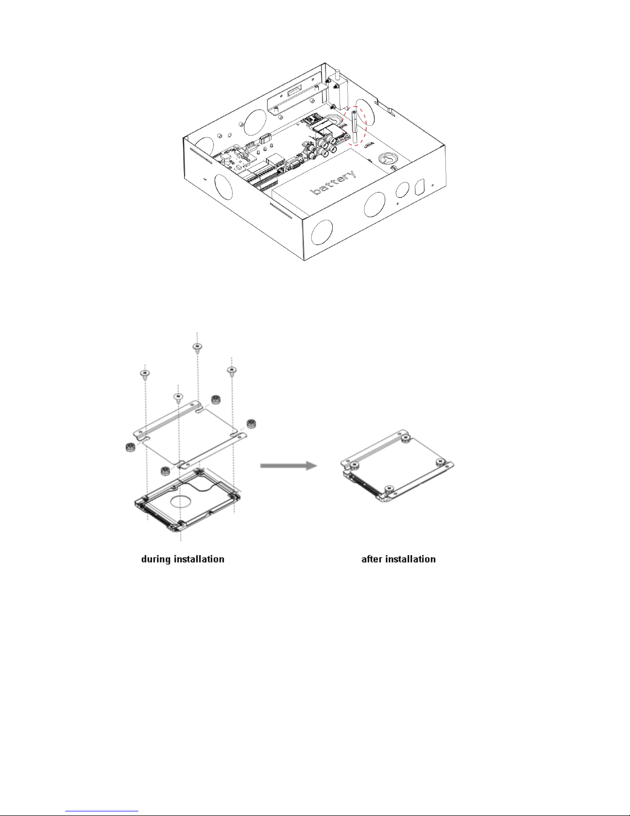
2.2.4 Install HDD
To install HDD:
Step 1. Inside the controller, insert 18.8MM screw, see Figure 2-11.
Page 13
8
Figure 2-11
Step 2. Place anti-knock ring into the four slots of HDD bracket, and HDD screw hole faces hole
on bracket, fasten anti-knock ring screw, see Figure 2-12.
Figure 2-12
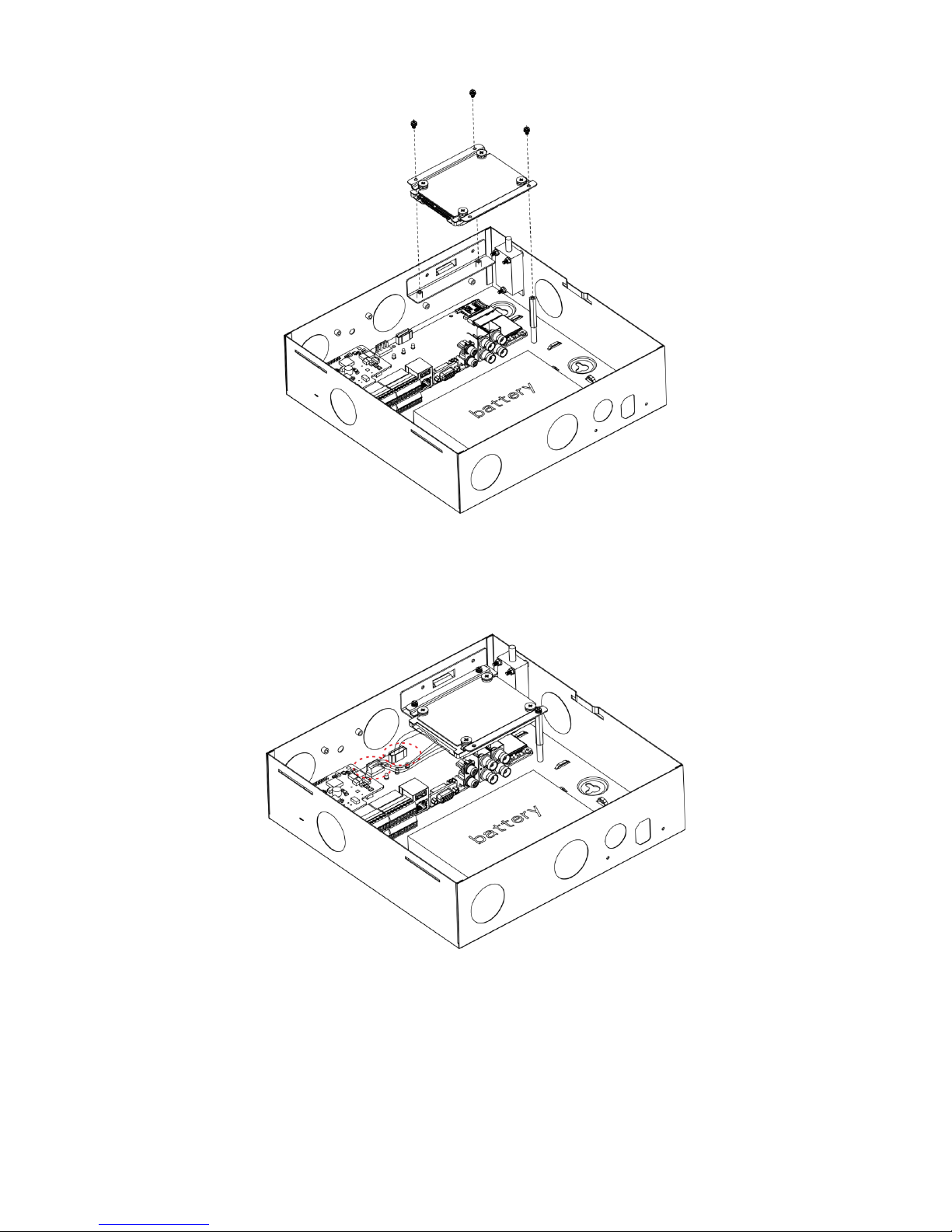
Step 3. Fix HDD with well installed bracket into the controller, see Figure 2-13.
Page 14
9
Figure 2-13
Step 4. Insert one end of HDD line into hardware, and insert the other end into HDD power port
and data port on controller, see Figure 2-14.
Figure 2-14
2.2.5 Wall Mount
The device supports wall mount and desktop placement.
Page 15
10
To mount on wall:
Step 1. Open device package, take out plastic expansion bolt and self-tapping screw.
Step 2. See Figure 2-15, dig hole on wall, insert the plastic expansion bolt and fasten self-
tapping screw.
Step 3. Hand the device on the screw.
Figure 2-15
2.3 Wiring
2.3.1 Port
Figure 2-16
No.
Name
Note
○
1
Power port
14.5V power supply
○
2
Battery port
Connect to 12V DC 7AH,leadacid battery
○
3
Siren port
Connect to siren
○
4
AUX power output
AUX1 connect to 12V 1A AUX
power;
AUX2 connect to 12V 500mA
○
9
○
8
○
7
○
5
○
16
○
15
○
14
○
13
○
10
○
11
○
2 ○3
○
1
○
4
○
6
○
12
○
17
Page 16
11
No.
Name
Note
AUX power, used for detector or
alarm keypad power supply
○
5
Sensor port
Support 5-ch sensor connection
○
6
LAN
Ethernet port
○
7
VGA port
Connect to VGA display
○
8
Audio output port
RCA audio output, talk output
○
9
Video input port
4-ch video input
○
10
GND
Grounding
○
11
Audio input port
4-ch audio input
○
12
USB port
Mouse
○
13
Alarm output port
1-ch relay output
○
14
Sensor port
3-ch sensor connection
○
15
RS485 port
A1B1 to alarm programming
keypad
A2B2 to extension alarm output
○
16
Telephone port
To user phone
○
17
User line port
To resident phone line
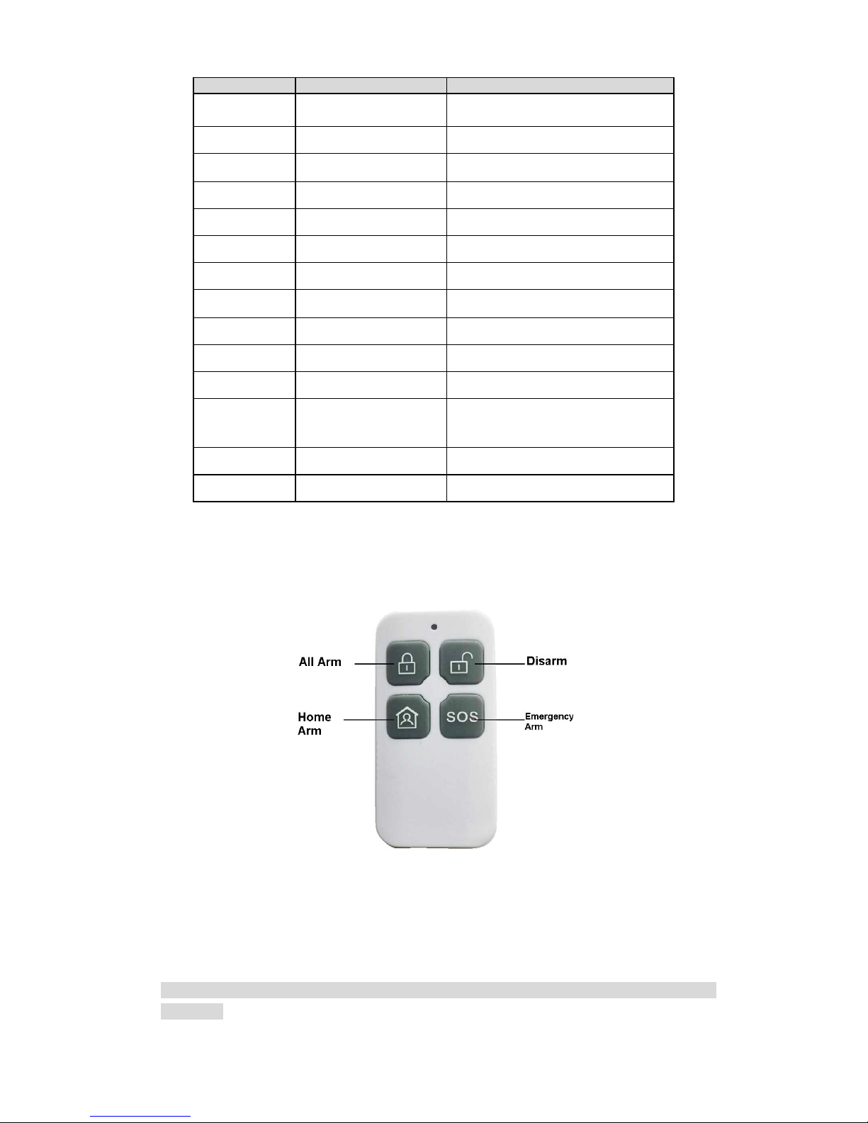
2.3.2 Remote Control Key
See Figure 2-17.
Figure 2-17
Note:
Press all arm button, after indicator is OFF immediately press emergency alarm button, to
out alarm.
Page 17

12
Press home arm button, after indicator is OFF immediately press emergency alarm button,
to instantly arm.
2.3.3 Power Line
Battery and DC power supply wirings are shown in Figure 2-18.
Figure 2-18
Note:
Every 3-5 year, change the lead-acid battery.
AUX power supply output 1 and AUX power supply output 2 has voltage change range when not
connecting to loading output:
1). When main power supply is in place, voltage is 14V not connecting to loading output.
2). When main power supply is not in place, uses battery, voltage change range is 9V~13V not
connecting to loading output.
2.3.4 Sensor Wiring
Sensor wiring is shown in Figure 2-19.
Figure 2-19
Page 18

13
Note:
Tail wire resistance is connection close to sensor end.
Before arming, you must configure sensor type in zone setup, as NO and NC, see Ch 4.3.1.
2.3.5 Alarm Output Wiring
Alarm output wiring is shown in Figure 2-20.
Figure 2-20
Page 19

14
3 WEB Login and Logout
3.1 Login
Before login, make sure the device is plugged to power and boot up.
Step 1. Open IE and input alarm controller address in the address column. For example, if your
alarm controller IP is 192.168.1.108, then please input http:// 192.168.1.108 in IE address
column. See Figure 3- 1.
Figure 3- 1
Note:
Before first login, make sure your PC and the controller are in the same network segment.
Please be aware that the initial IP of device is 192.168.1.108.
When first login, system shows control installation page, you shall follow instructions to install
control unit.
Step 2. Please input your user name and password.
Default factory name is admin and password is admin.
Step 3. Select “LAN” or “WAN” as login method.
Note:
The following takes LAN operation as an example.
Step 4. Click Login. System enters WEB homepage.
3.2 Logout
In alarm controller WEB page, select Logout tab to exit.
Note:
You must wait about 1 minute before you can login again.
Page 20

15
4 Arm/Disarm
4.1 Arm/Disarm
4.1.1 Before Arming
1. Check wiring at each part and external devices connected.
2. Confirm whether wireless device has been successfully coded wirelessly to controller.
3. Confirm whether zone parameter is set correctly.
4. Arm all once, check whether zone is abnormal. If there is abnormal, you will see prompt as
in Figure 4- 1.
Figure 4- 1
Now you can manually check sensor, and solve abnormality, or force it to arm without
solving abnormality.
4.1.2 WEB Disarm
4.1.2.1Arm
You can arm zone of alarm controller.
Step 1. Select SETUP>Zone Management>Arm/Disarm Zone. See Figure 4- 2.
Figure 4- 2
Page 21

16
Step 2. Set zone status of each zone.
Non-bypass: Zone can alarm in this status.
Bypass: The zone is temporarily shielded, when device arm again after being disarmed,
the bypass zone will go armed.
Isolated: The zone is stopped, when device arm again after being disarmed, it will
remain stopped.
Note:
These zones cannot be bypass: fire zone, 24-hour sound/mute zone, emergency zone.
Step 3. Select arm type, and arm zones. Click OK. See Chart 4- 1.
Step 4. Input username and password, to confirm.
If successfully arm, device will have prompt sound, enter exit delay status, according to set
exit delay, prompt once every 1s, and prompt twice every 1s in the last 10s.
If failed to arm, then device will prompt three times continuously. Now you need to check for
zone input, and you can force to arm.
Arm type, function and scene application are shown below:
Arm Type
Description
Application
Global Arm
Exit delay, entry delay
forbidden, all zones are under
warning status after being
armed
Such as housing being vacant for
period of time (eg vacation, etc.), you
need to close all zones before arming
Instant Arm
Exit delay, entry delay
forbidden; after being armed,
internal track, internal delay
zone will auto be bypassed
When users do not go out and expect
no one is using the entrance, you
need the user to close all doors and
windows before arming. For example,
rest at home
Out Mode
Exit delay, enable entry delay,
all zones are under warning
status after being armed
When no one left in the house used to
be closed before arming all zones
Home Arm
Exit delay, enable entry delay,
after being armed, internal
track, internal delay zone will
auto be bypassed
When the user does not have to go
out, but the person may be expected
to be used later on import and export
use, before arming requires the user
to close up all the doors and windows
Auto Arm
Exit delay, entry delay
forbidden of zones with auto
bypass ON (except 24-hour
zone), 8 periods for auto
arming
Users want the system to
automatically arm use, business on
the Standard, such as company after
work, to a certain point in time the
system will automatically arm
Forced Arm
Exit delay, entry delay
forbidden of zones with auto
bypass ON (except 24-hour
zone)
When a user does not want to deal
with the problem has been the use of
the zone
Chart 4- 1
Note:
Enter delay and exit delay refer to Ch 4.3.2.
When you successfully armed, you cannot change parameters of zone setup, network,
event and all other parameters in menu.
Page 22

17
4.1.2.2 Disarm
You can disarm arming of alarm controller.
Step 1. Select SETUP>Zone Management>Arm/Disarm Zone.
Step 2. Set zone type to Global Arm, click OK. Confirmation box pops up.
Step 3. Input username and password, confirm. Device has two tone prompt as successfully
disarmed.
4.1.3 Alarm Program Keypad Arm/Disarm
Please refer to Alarm Programming Keypad User’s Manual for wired programming keypad.
Wireless alarm programming keypad is in Ch 5.4 and 5.5.
4.1.3.3Arm
General Arm
Via keypad, arm the zone, alarm controller will response alarm signal in the zone.
Step 1. Press key, to next level menu.
Step 2. By pressing or , select arm/disarm, press .
Step 3. By pressing or , select arm, press .
Step 4. Input arm type no., press key.
Note:
1
Global arm
2
Instant arm
3
Out arm
4
Home Arm
5
Force to arm
Step 5. Input main user password, press key.
If successfully arm, device buzzer has tone prompt, and enter exit delay status, according to
set exit dekay, buzzer once per 1s, and buzzer twice per 1s for last 10s. If failed, then dvice will
buzzer three times continuously. Now you shall check whether there is zone input, and you can
force to arm.
Quick Arm
In keypad homepage, input user password, device has tone prompt, and enter exit delay status,
according to set exit dekay, buzzer once per 1s, and buzzer twice per 1s for last 10s. If failed,
then dvice will buzzer three times continuously. Now you shall check whether there is zone input,
and you can force to arm.
Note:
Quick arm will only arm globally.
4.1.3.4Disarm
General Disarm
Step 1. Press key, to next level menu.
Page 23

18
Step 2. By pressing or , select arm/disarm, press .
Step 3. By pressing or , select arm, press .
Step 4. Input user password, press .
Device has buzzer for twice, means successfully arm.
Quick Disarm
When controller is armed or disarmed with zone alarm triggered, in keypad homepage, input user
password, device has buzzer, means successfully arm.
4.1.4 Wireless Remote Control Disarm
4.1.4.1Arm
Via wireless remote control you can set all arm, home arm and etc.
Warning:
Wireless remote control must successfully coded before arming/disarming.
Press arm key on wireless remote control.
Alarm controller has tone prompt, as successfully armed, enter exit count down status, according
to set exit delay, beep once every 1s, and beep twice every 1s during the last 10s; if failed to arm,
device will have tone prompt 3 times. Now you shall check whether there is zone input, and you
can force to arm.
Note:
Please refer to Ch 2.3.2 for wireless remote control.
4.1.4.2Disarm
Under arming status, press disarm key on wireless remote control, device beeps twice, as
successfully disarmed.
4.2 Add and Delete Wireless Device
Note:
Under arming status, you cannot perform any operation.
Via wireless coding function, manage wireless device, to arm/disarm from wireless device.
Select SETUP>Zone Management>Wireless Code Match.
Figure 4- 3.
Page 24

19
Figure 4- 3
Add Wireless Remote Control
Click Enter Code Match, and press any key on wireless remote control.If successfully matched,
then WEB page will show wireless device info. See
After successfully matched, you can modify and delete wireless remote control info.
Modify wireless remote control info:
Click , pop up parameter window.
Parameter
Note
Enable
Select enable, the device can arm/disarm and alarm.
Mode
As normal and patrol. Normal is for arming/disarming and alarm; patrol is
for remote control patrol function, report to platform.
Username
Remote control name.
Delete wireless device:
Click , and confirm, delete the wireless remote control from system, as you cannot
arm/disarm or alarm.
Add Wireless Remote Sensor
Click Enter Code Match, and plug sensor to power, after indicator NO, dial vandal-proot switch,
indicator starts to flash. Wait about 10s, if indicator turns OFF, it means that matching is
successful. If indicator slowly flashes three times, it means that matching failed, and you shall
follow above steps again to connect.
Note:
Sensor code match is available for models of ARC5408B-W, ARC5408B-CW, ARC5408B-EW
and etc.
4.3 Zone Config
Set zone parameters, zone delay for each zone.
4.3.1 Zone Parameter Config
Page 25

20
For zone parameter in each zone (such as type, arm/disarm period, alarm link and etc.) to set.
Step 1. Select SETUP>Zone Management>Zone Setup. See Figure 4- 4.
Figure 4- 4
Step 1. Click . See Figure 4- 5.
Figure 4- 5
Parameter
Note
Enable alarm
input
Alarm input channel, as zone no.
Alarm Name
Customize zone name.
Zone Type
Click setup, select zone type (see below), and zone source type.
Arm/Disarm
Period
Click setup, in dropdown list, select day, set period.
Page 26

21
Parameter
Note
Device Type
NO and NC, set according to device.
Record Channel
Select corresponding record channel no., can re-select. When alarm occurs,
system turns on corresponding channel to record.
Record Delay
Set delay, when alarm ends, alarm record will continue for a certain period.
Alarm Output
Alarm link output channel
Snapshot
When alarm occurs, trigger and snapshot the selected channel
Alarm Upload
Upload alarm info
Buzzer
When alarm, enable buzzer to alarm
SMS
When alarm, send SMS to set number
Audio Play
When abnormality occurs, play the selected audio file
Siren Output
Control
When alarm occurs, enable siren.
Call Center
When alarm occurs, report to call center.
Zone Type
Description
Application
Fire Zone
Device will send alarm report to alarm
center.
Not affected by arming/disarming, bypass.
Keypad will show this zone with alarm tone
prompt plus send report to alarm center;
not affected by arming/disarming, cannot
be bypasses. Alarm tone prompt
Mainly used heat
detectors, smoke
detectors
24-hour
Sound
Zone
Self-carried link siren, buzzer, no need to
set
Send alarm report to alarm center.
Not affected by arming/disarming, bypass.
Keypad will show this zone, and send
alarm prompt.
Emergency key
24-hour
Mute Zone
Device does not link alarm, buzzer.
Send report to alarm center.
Not affected by arming/disarming, bypass
Jewelry stores, banks
and other emergency
button
Emergency
Zone
Send report to alarm center.
Not affected by arming/disarming, bypass
Keypad will show this zone, and send
alarm prompt.
Emergency key
In/out Zone
1
Global arm, instant arm cannot provide
entry delay
Out, in mode, provide entry and zone 1
enter delay
After arming, exit delay becomes effective
immediately.
The main entrance
with the keypad
disarming necessary
place
In/out Zone
2
Global arm, instant arm cannot provide
entry delay
Out, in mode, provide entry and zone 2
enter delay
After arming, exit delay becomes effective
immediately.
The main entrance
with the keypad
disarming necessary
place
Internal
Zone
Home Arm and instant arm, internal zone
will be bypassed.
When out arm, provide entry zone 1 entry
delay and exit delay.
Global arm, no entry delay, but has exit delay.
Hall, lounge detectors
can be installed
indoors
External
After arming takes effect, no entry or exit delay
Windows, fences,
Page 27

22
Zone Type
Description
Application
Zone
to trigger alarm.
gates and other
outdoor periphery
Step 2. Depends on condition, config parameter.
Step 3. Click OK to save. Click Copy to copy setup to other channels.
4.3.2 Zone Delay Config
Entry delay: If entry delay time is set to 10s, after user set arming and trigger alarm, the user
has 10 s to disarm. If the user successfully disarms within the 10s, system will not link alarm.
Otherwise, the system will link alarm.
Exit delay: If exit delay time is set to 10s, when a user arms, within 10, trigger to zone is
invalid.
Step 1. Select SETUP>Zone Management>Latch. See Figure 4- 6.
Figure 4- 6
Step 2. Input entry delay and exit delay time.
Note:
Entry/exit delay of zone 1 is valid for entry/exit zone 1 and internal zone.
Entry/exit delay of zone 2 is valid for zone 2.
Step 3. Click OK to save.
4.4 Emergency Alarm Config
Device provides fire alarm, endures, robbery, medical emergency, remote control alarm and
other event emergency alarm function.
Step 1. Select SETUP>EVENT>Alarm Link, click Emergency Alarm. See Figure 4- 7.
Page 28

23
Figure 4- 7
Step 2. Select event type, and set alarm link item. Please refer to Ch 4.3.
Step 3. Click OK to save.
Fire, duress, robbery, medical emergency alarms need alarm programming keypad to
achieve, see:
Type
Operation
Fire
Long press key for 3s, buzzer will start to alarm, device
sends fire alarm info to alarm controller.
Duress
In homepage, input user 22’s password (123457)
Robbery
Long press【SOS】 key for 3s
Medical
Emergency
Long press【2】key
Note:
Wireless alarm keypad only supports SOS alarm and duress alarm.
4.5 Siren and Alarm Output Config
4.5.1 Siren Output Config
Set siren output duration when alarm occurs.
Step 1. Select SETUP>Zone Management>Siren Output.
See Figure 4- 8.
Page 29

24
Figure 4- 8
Step 2. Input siren output duration (default is 5min).
Step 3. click OK.
4.5.2 Relay Output Config
Set relay output channel, type and period.
Step 1. Select SETUP>Zone Management>Relay Output. See Figure 4- 9.
Figure 4- 9
Step 2. Select replay channel, type and duration.
Type
Note
Page 30

25
Force
Actively enable relay output
Stop
Actively disable relay output
Schedule
Config link alarm output, trigger alarm, alarm output will output
until auto OFF
Step 3. In auto output setup, set auto output date and start/end time. Until the start time, relay will
automatically enable, until end time it will disable.
Step 4. Click OK.
4.5.3 Buzzer Output Config
When alarm occurs, enable buzzer during alarm time.
Step 1. Select SETUP>Zone Management>Buzzer Output. See Figure 4- 10.
Figure 4- 10
Step 2. Input buzzer output duration.
Step 3. Click OK.
4.6 Failure Config
When HDD, network, power supply, sensor have failure, device provides related link alarm
functions, but you need to set first.
HDD, network, power supply
Step 1. Select SETUP>Event>Failure Link. See Figure 4- 11.Click HDD (or Network, Power or
Other Failure tab)
Page 31

26
Figure 4- 11
Step 2. Select event type and set failure link parameters. Click OK to save. Please refer to Ch
4.3.
Failure Type
Situation
Indicator Status
HDD
No HDD
When HDD has failure, HDD
indicator is ON.
HDD error
Capacity warning
Network
Offline alarm
When network has failure,
network indicator is ON. See
Figure 4-12.
IP conflict
MAC conflict
Power
Main power down
None
Battery outage
Battery low
Other
Failure
PSTN cut
None
Device vandal-proof
Figure 4- 12
Step 3. Click OK.
Detector failure alarm parameter setup
Page 32

27
Step 1. Select SETUP>Event>Alarm Link>Detector Abnormal Alarm. See Figure 4- 13.
Figure 4- 13
Step 2. Select failure event, and set parameter. See chart below Figure 4-5.
Step 3. Click OK to save.
Note:
Refer to 2.3.4, if the zones Z1 and G interfaces directly connected in series with the line and
short-circuit alarm function is enabled, the device will issue a short circuit alarm signal.
If the zone is not connected detector circuit alarm enabled, the device will report the breaking
event, but does not affect use. If you want to eliminate the circuit, the zone can be isolated or two
2.2k resistor in series with the access zones.
Detector failure alarm is not controller by arm and disarm.
4.7 Video Alarm Config
Note:
Video alarm is not controlled by arm/disarm.
4.7.1 Motion Detection
Via system analysis of video image, when it detects mobile signal with preset sensitivity, it will
immediately enable video detection alarm. System supports three video detection types: motion
detection, video loss, tampering.
Step 1. Select SETUP>Event>Video Detect. See Figure 4- 14.
Page 33

28
Figure 4- 14
Step 2. Select tab you want to config.
Step 3. Configure parameter.
Step 4. Click OK.
Click Copy to copy setup to other channels.
Parameter
Name
Note
Enable
Channel
Select channel to set.
Arm/disarm
Period
Set motion detection period, as detection is enabled only in the set period.
Anti-dither
Set Anti-dither time, range is 0~600s
Sensitivity
Sensitivity setup has 6 levels, mainly take brightness as subject. The higher
the number the higher the sensitivity. Level 1 is min, level 6 is max, default
is level 3.
Region
Set motion detection region. The red area is motion detection fortified area,
drag the mouse to drag the area to remove the red, that is undefended
areas. Only fortified area mobile signal appears to be detected.
Record
Channel
When you select the desired video channels (check), an alarm occurs, the
system automatically starts the channel for video
Record Delay
Record delays for certain period, and stops. Range:10~300
Alarm Output
When alarm occurs, external device with link alarm ports enabled
Snapshot
When motion detection occurs, snapshot the selected channel.
Audio Prompt
Play the selected audio file when motion detection.
Buzzer
When alarm is enabled, enable buzzer.
SMS
When alarm is enabled, send SMS to specific number.
Log
In system log, record motion detection log info.
Siren
Enable siren when alarm occurs.
4.7.2 Video Loss
Via analyzing video image, when system detects channel has video loss, device will alarm.
Step 1. Select SETUP>EVENT>Video Loss. See Figure 4- 15.
Page 34

29
Figure 4- 15
Step 2. Select tab you want to configure. See chart below Figure 4-14.
Step 3. Click OK.
Click Copy to copy setup to other channels.
4.7.3 Tampering Detection
When camera is tempered, or video is only output one color due to light and other factors, it
cannot monitor the site. Via setting tampering alarm, we can prevent this situation.
Step 1. Select SETUP>EVENT>Tampering. See Figure 4- 16.
Figure 4- 16
Step 2. Select tab you want to configure. See chart below Figure 4-14.
Step 3. Click OK.
Click Copy to copy setup to other channels.
4.8 Event Report Config
You can select network priority and report mode when alarm occurs. When alarm occurs, alarm
info will be reported according your selected report mode.
Page 35

30
Step 1. Select SETUP>Event>Report Mode. See Figure 4- 17.
Figure 4- 17
Step 2. Select network priority and report mode.
PRIORITY: apply to TCP/IP protocol transmission, by setting network priority; you can select
to transmit via wired Ethernet or 3G/4G wireless network transmission.
Setup
Note
Wired only
Event via wired Ethernet network transmit to alarm
center
3G/4G network
Event via 3G/4 wireless network transmit to alarm
center
Wired network priority,
failed convert to 3G/4G
network
Event priority through a wired Ethernet transmission
to the central station, if the cable network failure,
switching to 3G / 4G network transmission; if a wired
network is restored, then the next alarm event
switches to the wired network.
Report mode: Via report mode config, you can select transmit event via Ethernet or telephone
line.
Setup
Note
Not report
Under this mode, event will not be reported to
network and call center
Report to network center 1
only
Evert will be reported to network center 1(auto
register, direct connect IP , SDKDemo, WEB)
Dial call center 1 only
Event will be reported to call center 1(center
config see Ch 4.10.1)
Dial call center 1 and if
failed, dial 2
Event will be reported to call center 1, if failed,
dial call center 2
Dial call center 1 and 2 at
the same time
Event will be reported to call center 1 and 2
Sent to network center 1, if
failed, send to call center 1
Event will be reported to network center 1, if
failed, event will be sent to call center 1
Send to network center 1
Event will be reported to both network center 1
Page 36

31
Setup
Note
and call center 1
and call center 1
Step 3. Click OK to save.
4.9 Event Info View
You can view alarm info via WEB or alarm programming keypad,
Via WEB:
Select ALARM>Zone Event, you can view each zone’s arming/disarming info and detector
abnormality.
Figure 4- 18
Via alarm programming keypad:
Long press key to shoe zone 1~10 alarm info. See below. 00*1234567890 means
zone 1~10 in group 00. If you want to view zone 11~20 alarm info please input 01 here, so forth.
Zone 21~30 is 02; zone 31~40 is 03.
When check box is empty, the zone is normal. When check box is black, the zone is under alarm
status. When check box is B/W, the zone is under source trigger but no alarm output.
00*1 2 3 4 5 6 7 8 9 0
4.10 Network Config
4.10.1 Call Center
You can set call center parameter, when alarm occurs, system will send alarm info to call center.
Warning:
If you want to send alarm info to call center, you must check “call center” when you set
alarm link.
Step 1. Select SETUP>Network>Call Center. See Figure 4- 19.
Page 37

32
Figure 4- 19
Step 2. Configure parameters, click OK. See
Parameter
Note
Call Group
By default there are two groups of call, you can select
in the dropdown list.
Center Name
Customize center name.
Center Number
Call center number.
Protocol Type
Use default value, default is CID
Signal Transmission
Mode
Use default, default is DTMF 5/S
Dial Attempts
If call center does not pick up call, it will try this number
of times, range is 1~9
Dial Delay
Time interval between two attempts
User Code
Call center provided user code, default is 0000
Step 3. Click OK.
4.10.2 Register
When controller connects to WAN, it will auto report its current position to server specific by user,
to provide convenience for user access.
Step 1. Select SETUP>Network>Register. See Figure 4- 20.
Page 38

33
Figure 4- 20
Step 2. Click check box, enable this function.
Step 3. Configure controller IP address, port and sub device ID.
Parameter
Note
Host IP
Need to register to server IP or server domain.
Port
Port of server used to auto register
Sub-device ID
Allocated by server, used as the controller ID
Step 4. Click OK.
4.10.3 P2P
After P2P function is enabled, open mobile client software, directly input SN or scan the twodimension code, save setup as you can arm/disarm on client, while achieve goal to manage
multiple controllers. You do not need to apply for dynamic domain name, map port and deploy
transit server.
Warning:
To use this function, you must connect the controller to WAN. Otherwise, this function is disabled.
Step 1. Select SETUP>Network>P2P. See Figure 4- 21.
Page 39

34
Figure 4- 21
Step 2. Click check box to enable P2P.
Step 3. Click Save.
After setup is done, “status” is online, as P2P registration is successful.
When P2P registration is successful, you can scan QR code via mobile phone or directly enter
SN to add controller, to access and manage controller, please refer to Smart Phone Client User’s
Manual.
Page 40

35
5 Wireless Alarm Programming Keypad Operation
Wireless alarm programming keypad model is ARK20C-MW, applicable for ARC5408B-W,
ARC5408B-CW, ARC5408B-EW, ARC5408C-W, ARC5408C-CW, ARC5408C-EW controller
models.
5.1 Key
Figure 5-1
Key
Name
Note
Menu
Click this key to:
Enter main menu
Enter *.
Arm
This key is used to quickly arm. After arming, you can
see “A” at the upper-left corner on screen.
Note:
Valid in homepage only.
Home Arm
This key is used to quickly arm at home. After arming,
you can see “S” at the upper-left corner on screen.
Note:
Valid in homepage only.
Disarm
This key is used to quickly disarm. After disarming, you
can see “D” at the upper-left corner on screen.
Note:
Valid in homepage only.
Emergency
Alarm
Long press this key for 3s, buzzer starts to alarm, and
send alarm info to controller.
Return
Click this key, you can:
Wireless match code.
Delete wrong input
Back to previous menu.
Page Up
In menu, click this key to page up.
Page Down
Click this key, you can :
Page 41

36
Key
Name
Note
In menu, click this key to page down.
Long press this key to view zone alarm info.
OK
Click this key, you can:
Enter sub menu
Save setup.
Restart keypad.
5.2 Wireless Match Code
Before use, you must wireless match code with alarm controller. When successfully match code,
you can set and arm/disarm.
Step 1. In WEB Wireless Code interface, click Enter Code Match. See Figure 5-2.
Figure 5-2
Step 2. Power up wireless alarm programming keypad, and select language.
System shows it is matching code.
Step 3. Click Return.
If it shows matching is successful, then code match is complete. If it shows matching failed,
then click return key to match again.
Note:
For already matched keypad, if you want to match to another controller, long press OK key to
restart, and match code.
5.3 Before Operation
5.3.1 Notice
Under this environment, alarm keyboard is plugged to power and registration is
successful, enter main interface.
[Menu]+[Up/down page selection]+[OK]+[Up/down page sub
selection]+[OK]+[Operation]
Note:
Different operations and methods refer to each chapter.
5.3.2 Function Menu List
Page 42

37
Function
Sub Function
Function
Sub Function
Arm/Disarm
Arm
Disarm
Bypass isolate
COM
Network
Tel
Zone
Type
Link
Output
Siren
Alarm output
Other
Reset
Key tone
Time
User
Reboot
Status
Zone
Access control
Version
Time
COM
Host status
Output
5.3.3 Prompt Explanation
You may see the following prompt on screen:
Setup failed: Controller setup error.
No right: A user does not have certain right to operate.
Invalid operation: Maybe that version of controller does not match version of alarm
programming keypad.
Reading: It is reading status of controller.
Setting: Controller is responding setup of wireless alarm programming keypad.
5.3.4 User
5.3.4.1User Right
Different user has different right, see below:
User Type
Code
Default
Password
Right
Note
Administrator
00
123456
Arm/disarm
Bypass
isolate
User
managemen
t
Reset
controller
First login user please
change your password,
please refer to Ch 5.3.1
and 5.3.4.2.
Operator
01~20
—
Arm/disarm
Bypass
isolate
By default, there is no
operator user, you shall
configure operator as
you need, please refer
to ] Ch 5.3.1 and 5.3.4.3.
Installer
21
909090
Set
—
Duress User
22
123457
Arm/disarm
Reset
controller
When a duress user
operates, it will send
duress report.
5.3.4.2Modify Password
Operation method: [Encode command] +[OK]+[Admin password]
Encode command is composed as follows:
Page 43

38
①
1 10②888888
③
No.
Note
①
Encode address, means the operation is to modify
password, default is 1
②
User encode,range is 00~22. 00 is admin user,01~20
is operator user,21 is installer user,22 is duress user.
③
New password, composed of 6 digits of number.
Note:
Different user cannot have repeated password.
5.3.4.3Add User
Operation method: [Encode command]+[OK]+[Admin password].
Encode command is composed as follows:
①
1 10②888888
③
No.
Note
①
Encode address, means the operation is to modify
password, default is 1
②
User encode,range is 00~22。00 is admin user,01~20
is operator user,21 is installer user,22 is duress user.
③
New password, composed of 6 digits of number.
5.3.4.4Delete User
Operation method: [Encode command]+[OK]+[Admin password].
Encode command is composed as follows:
①
2 10
②
No.
Note
①
Encode address, means the operation is to delete
user, default is 2
②
Code to delete user.
Page 44

39
5.4 Arm
When alarm controller and detector work as normal, via wireless alarm keypad to arm zone,
alarm controller will respond to alarm signal in zone.
Quick Arm
Operation method: Before you enter any menu, click / and press administrator
password/opertor password.
Operation result:If successfully arm, keypad shows “A/S” at the upper-left corner. Controller will
have tone prompt, and enter exit delay status, according to set exit dekay, buzzer once per 1s,
and buzzer twice per 1s for last 10s. If failed, then dvice will buzzer three times continuously.
Now you shall check whether there is zone input, and you can force to arm.
Note:
: quickly arm.
: quickly arm at home.
General Arm
Operation method: [arm type encode]+[OK]+[Admin password/operator password]
Operation result:If successfully arm, controller will have tone prompt, and enter exit delay status,
according to set exit dekay, buzzer once per 1s, and buzzer twice per 1s for last 10s. If failed,
then dvice will buzzer three times continuously. Now you shall check whether there is zone input,
and you can force to arm.
Arm type:
1
Global arm
2
Instant arm
3
Out arm
4
Home Arm
5
Force to arm
5.5 Disarm
When zone is armed, you can disarm zone.
Quick Disarm
Operation method: Before you enter any menu, click to enter administrator
password/operator password.
General Disarm
Operation method: [OK]+[Admin/operator password].
5.6 Bypass Isolation
Non-bypass: the zone is at normal status, you may perform various arming operations.
Page 45

40
Bypass: This zone is shielded for the arming, when disarm, the zone will resume non-bypass
status.
Isolate: The zone is stop, when device arm again after disarming, the isolated zone is still
stop
Operation method: [Encode command]+[OK]+[Admin password/operator password]
Encode command is composed as follows:
1 001
①
②
No.
Note
①
Bypass/isolation type code.
②
Zone number,range is 001~256. Such as zone
1,number is 001
5.7 Zone Setup
5.7.1 Type Setup
You can set zone parameter.
Operation method: [encode command]+[OK]+[Installer password].
Encode command is as follows:
1
④
1
③
001①00
②
No.
Note
Zone number,range is 001~256. Such as zone
1,no. is 001
Zone type code
Enter delay,range is 0~240,unit is s,besides
delay zone, when set other zone, you can ignore
this parameter.
Exit delay,range is 0~240,unit is s,besides
delay zone, other zone setup can ignore this
parameter.
Page 46

41
Code
Zone Type
Code
Zone Type
00
Instant zone
08
All-day zone
01
Fire zone
09
Internal zone
02
Medical zone
10
External zone
03
Duress zone
11
Not alarm
04
Delay zone
12
24-hour sound
zone
05
Enter/exit
zone 1
13
24-hour mute
zone
06
Enter/exit
zone 2
14
Emergency zone
07
Track zone
-
-
5.7.2 Link Setup
You can set zone alarm link parameter.
Operation method: [Encode command]+[OK]+[Installer password].
Encode command is composed as follows:
1
③②
0
001
①
01
④
No.
Note
①
Zone no., range is 001~256. Such as zone 1,no.
is 001
②
Link type:0-siren,1-alarm output,2-buzzer
③
Link enable:0-not enable,1-enable
④
Link no. is alarm output no., default is 0
5.8 Other Setup
5.8.1 Reset Controller
Via keypad you can reset alarm controller, so alarm controller will restore default settings.
Operation method: enter [installer password].
5.8.2 Key Tone
You can enable or disable key tone.
Operation method: enter [code command].
Note:
Code command: 1- enable, 0-disable.
5.8.3 System Time
Page 47

42
You can set system date and time.
Operation: [code command] +[OK]+[installer password].
Code command includes date command and time command, see below:
2
①
01
③
2015
②
01
④
No.
Note
①
Code address, means the operation is to set system date,
default is 2.
②
Year , range is 2000~2043.
③
Month, range is 1~12.
④
Day, range is 1~31.
22③22
④
10
②
①
1
No.
Note
①
Code address, means the operation is to set system tiime,
default is 1.
②
Hour, range is 0~23.
③
Minute, range is 0~59.
④
Second, range is 0~59.
Note:
If you want to set date and time at the same time, please follow the above operation twice, set
date first and then set time.
5.8.4 Reboot
Via keypad you can reboot alarm controller.
Operation method: enter [installer password].
5.9 COM Setup
5.9.1 Network
You can set controller IP address, subnet mask, gateway and port.
Operation method: [code command]+[OK]+[installer password].
Page 48

43
①
1 192#028#006#009#
②
No.
Note
①
Network parameter code:1-IP address,2-subnet
mask,3-gateway,4-port
②
Address code, format is XXX#XXX#XXX#XXX#;or port,
format is [port] + [#].
Note:
“#” can be replaced with “*”.
5.9.2 Telephone
You can set 2 groups of tel alarm center and tel alarm center enable option.
Operation method: [code command]+[OK]+[installer password].
①
1 0571888888886666
②
No.
Note
①
Tel number composition:1-set first group phone
number,2-set second group phone number
②
Telephone number, max of 16 digits of number.
5.10 Output Setup
5.10.1 Siren Output
You can enable or disable siren output function.
Operation method: enter [code command] +[installer password]
Note:
Code command: 1-enable force to output, 0-disable.
5.10.2 Alarm Output
You can set alarm output mode, and control alarm output.
Set alarm output mode
Operation method: enter [code command]+[installer password]
001
0
②
①
2
③
Page 49

44
No.
Note
①
Code address, means this operation is to set alarm output
mode, default is 2.
①
Alarm output mode:0-auto,1-force,2-OFF
②
Alarm output no., range is 001~064.
Control alarm output
In auto mode, you can enable or disable alarm output.
Operation method: enter [code command]+[installer password].
001
1
②
①
1
③
No.
Note
①
Code address, means this operation is to control alarm
output, default is 1.
②
Alarm output enable:1-enable alarm output,0-disable
alarm output
③
Alarm output no., range is 001~064.
5.11 View System Status
5.11.1 Zone
You can search zone system status, including zone no., arm/disarm status (arm, disarm, bypass),
alarm status (alarm, non-alarm), zone type (entry/exit, all day, delay. In delay display, front time
is entry delay, and rear time is exit delay).
Operation method: enter [code command]+[OK]
Note:
Here code command is the zone no., range is 001~256. For example, for zone 1, enter 001.
5.11.2 Host Version
You can view versions of wireless alarm programming keypad and alarm controller.
Operation method: [OK].
Note:
Wireless alarm programming keypad version is shown by letter “K”.
Alarm controller version is shown by letter “F”.
5.11.3 System Time
You can view system time of alarm controller.
Operation method: [OK].
Page 50

45
5.11.4 Communication
You can search controller IP address, subnet mask, gateway, port and RS485 address.
Operation method: enter [code command] + [OK] +[administrator/operator password]
Search IP address, subnet mask, gateway and port no. commands are shown below.
①1②
1
No.
Note
①
Code address, means this operation is to search IP
address, subnet mask, gateway and port.
②
Search content:1-IP address,2-subnet mask,3-
gateway,4-port.
Code command to search RS485 address: enter number 【2】.
5.11.5 Host Status
You can view each module status in alarm controller.
Operation method: [OK].
Result is shown below.
Note:
When check box is black, it means corresponding module has error. When check box is empty, it
means corresponding module is normal.
5.11.6 Output
You can search controller siren status and output stauts.
Operation method: enter [code command] + [OK].
Search siren status code command: enter number key 【1】.
Code command to search output status is shown below.
2 001
①
②
No.
Note
①
Code address, means this operation is to search alarm
output status of a certain zone, default is 2.
Page 51

46
②
Alarm no., range is 001~064.
Page 52

47
Appendix 1Contact ID Event Code
CID Code
Description
100
Medical
110
Fire
120
SOS sound
121
Duress
122
24-hour mute
123
24-hour sound
130
Robber
131
External zone
132
Internal zone
134
Entrance/exit zone
301
Main power outage
302
Low battery
350
Communication failure(MAC conflict, IP
conflict, offline)
351
PSTN offline
401
Arm/disarm
403
Auto arm
405
Force to arm
408
Instant arm
441
Home arm
601
Manual test
602
Period test
945
HDD capacity warning
946
HDD failure
Note
For detailed operation introduction, please refer to our resource CD included in your
package for electronic version of the User’s Manual.
Slight difference may be found in user interface.
All the designs and software here are subject to change without prior written notice.
All trademarks and registered trademarks mentioned are the properties of their
respective owners.
If there is any uncertainty or controversy, please refer to the final explanation of us.
Please visit our website for more information.
 Loading...