

Page 1

Video Alarm Control Panel
User’s Manual
V1.0.1
Page 2

I
Legal Statement
Trademark
VGA is the trademark of IBM.
Windows logo and Windows are trademarks or registered trademarks of Microsoft.
Other trademarks and company names mentioned are the properties of their respective
owners.
Disclaimer
Within the scope allowed by applicable laws, in any case, this company won’t compensate
any special, contingent, indirect and secondary damages resulting from relevant contents
and products described in this document, nor compensate any losses in profits, data,
reputation, document loss or expected savings.
Products described in this document are provided “as is”. Unless required by applicable
laws, this company doesn’t provide any express or implicit guarantees for all contents in
the document, including but not limited to guarantees for marketability, quality satisfaction,
application to specific purpose and non-infringement of third-party rights.
About this Document
This document is for reference only. Please refer to the actual product for more details.
The user shall undertake any losses resulting from violation of guidance in the document.
In case that PDF document cannot be opened, please upgrade the reading tool to the
latest version or use other mainstream reading tools.
This company reserves rights to revise any information in the document anytime; and the
revised contents will be added to the new version without prior announcement. Some
functions of the products may be slightly different before and after revision.
The document may include technically inaccurate contents, inconsistencies with product
functions and operations, or misprint. Final explanations of the company shall prevail.
Page 3

II
Cybersecurity Recommendations
Mandatory actions to be taken towards cybersecurity
1. Change Passwords and Use Strong Passwords:
The number one reason systems get “hacked” is due to having weak or default passwords. It is
recommended to change default passwords immediately and choose a strong password
whenever possible. A strong password should be made up of at least 8 characters and a
combination of special characters, numbers, and upper and lower case letters.
2. Update Firmware
As is standard procedure in the tech-industry, we recommend keeping NVR, DVR, and IP
camera firmware up-to-date to ensure the system is current with the latest security patches and
fixes.
“Nice to have” recommendations to improve your network security
1. Change Passwords Regularly
Regularly change the credentials to your devices to help ensure that only authorized users are
able to access the system.
2. Change Default HTTP and TCP Ports:
● Change default HTTP and TCP ports for systems. These are the two ports used to
communicate and to view video feeds remotely.
● These ports can be changed to any set of numbers between 1025-65535. Avoiding the
default ports reduces the risk of outsiders being able to guess which ports you are using.
3. Enable HTTPS/SSL:
Set up an SSL Certificate to enable HTTPS. This will encrypt all communication between your
devices and recorder.
4. Enable IP Filter:
Enabling your IP filter will prevent everyone, except those with specified IP addresses, from
accessing the system.
5. Change ONVIF Password:
On older IP Camera firmware, the ONVIF password does not change when you change the
system’s credentials. You will need to either update the camera’s firmware to the latest revision
or manually change the ONVIF password.
6. Forward Only Ports You Need:
Page 4

III
● Only forward the HTTP and TCP ports that you need to use. Do not forward a huge range of
numbers to the device. Do not DMZ the device's IP address.
● You do not need to forward any ports for individual cameras if they are all connected to a
recorder on site; just the NVR is needed.
7. Disable Auto-Login on SmartPSS:
Those using SmartPSS to view their system and on a computer that is used by multiple people
should disable auto-login. This adds a layer of security to prevent users without the appropriate
credentials from accessing the system.
8. Use a Different Username and Password for SmartPSS:
In the event that your social media, bank, email, etc. account is compromised, you would not
want someone collecting those passwords and trying them out on your video surveillance
system. Using a different username and password for your security system will make it more
difficult for someone to guess their way into your system.
9. Limit Features of Guest Accounts:
If your system is set up for multiple users, ensure that each user only has rights to features and
functions they need to use to perform their job.
10. UPnP:
● UPnP will automatically try to forward ports in your router or modem. Normally this would be a
good thing. However, if your system automatically forwards the ports and you leave the
credentials defaulted, you may end up with unwanted visitors.
● If you manually forwarded the HTTP and TCP ports in your router/modem, this feature should
be turned off regardless. Disabling UPnP is recommended when the function is not used in real
applications.
11. SNMP:
Disable SNMP if you are not using it. If you are using SNMP, you should do so only temporarily,
for tracing and testing purposes only.
12. Multicast:
Multicast is used to share video streams between two recorders. Currently there are no known
issues involving Multicast, but if you are not using this feature, deactivation can enhance your
network security.
13. Check the Log:
If you suspect that someone has gained unauthorized access to your system, you can check
the system log. The system log will show you which IP addresses were used to login to your
system and what was accessed.
14. Physically Lock Down the Device:
Page 5

IV
Ideally, you want to prevent any unauthorized physical access to your system. The best way to
achieve this is to install the recorder in a lockbox, locking server rack, or in a room that is
behind a lock and key.
15. Connect IP Cameras to the PoE Ports on the Back of an NVR:
Cameras connected to the PoE ports on the back of an NVR are isolated from the outside world
and cannot be accessed directly.
16. Isolate NVR and IP Camera Network
The network your NVR and IP camera resides on should not be the same network as your
public computer network. This will prevent any visitors or unwanted guests from getting access
to the same network the security system needs in order to function properly.
Page 6
V
Preface
Overview
This document elaborates device structure, installation and system functional operation of
video alarm control panel.
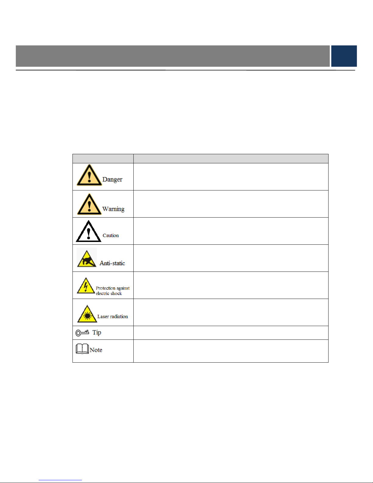
Symbol Definition
The following symbols may appear in this document. And their meanings are as follows:
Symbol
Note
It indicates a potentially hazardous situation which, if not avoided, could
result in death or serious injury.
It indicates a moderate or low level of potential danger which, if not
avoided, could result in minor or moderate injury.
It indicates a potential risk that, if ignored, could result in damage to
device, loss of data, degraded performance, or unpredictable results.
It means electrostatic-sensitive device.
It means high-voltage danger.
It means intensive laser radiation.
It means that it can help you to solve some problems or save your time.
It means the additional information, which is to emphasize or
supplement.
Page 7

VI
Important Safeguards and Warnings
The following description is the correct application method of the device. Please read the
manual carefully before use, in order to prevent danger and property loss. Strictly conform to
the manual during application and keep it properly after reading.
Operating Requirement
Please modify default password timely after device deployment, in order not to be
embezzled.
Please don’t place and install the device in an area exposed to direct sunlight or near heat
generating device.
Please don’t install the device in a humid, dusty or fuliginous area.
Please keep its horizontal installation, or install it at stable places, and prevent it from
falling.
Please don’t drip or splash liquids onto the device; don’t put on the device anything filled
with liquids, in order to prevent liquids from flowing into the device.
Please install the device at well-ventilated places; don’t block its ventilation opening.
Use the device only within rated input and output range.
Please don’t dismantle the device arbitrarily.
Please transport, use and store the device within allowed humidity and temperature range.
Power Requirement
Please make sure to use batteries according to requirements; otherwise, it may result in
fire, explosion or burning risks of batteries!
To replace batteries, only the same type of batteries can be used!
The product shall use electric cables (power cables) recommended by this area, which
shall be used within its rated specification.
Please use power supply that meets SELV (safety extra low voltage) requirements, and
supply power with rated voltage that conforms to Limited Power Source in IEC60950-1. For
specific power supply requirements, please refer to device labels.
Products with category I structure shall be connected to grid power output socket, which is
equipped with protective grounding.
If power plug or appliance coupler is a disconnecting device, please keep its convenient
operation.
Page 8

VII
Table of Contents
Legal Statement ..................................................................................................................................................... I
Cybersecurity Recommendations ................................................................................................................... II
Preface .................................................................................................................................................................... V
Important Safeguards and Warnings ............................................................................................................. VI
1 Overview .............................................................................................................................................................. 1
1.1 Product Introduction ................................................................................................................................. 1
1.2 Product Function ....................................................................................................................................... 1
1.3 Typical Network ......................................................................................................................................... 1
2 Device Structure ................................................................................................................................................ 3
2.1 Structure Dimension ................................................................................................................................. 3
2.2 Front Panel ................................................................................................................................................ 4
2.3 Rear Panel ................................................................................................................................................. 5
3 Installation ........................................................................................................................................................... 7
3.1 SD Card Installation .................................................................................................................................. 7
3.2 SIM Card Installation ................................................................................................................................ 7
3.3 Battery Installation .................................................................................................................................... 8
3.4 Cable Installation....................................................................................................................................... 9
3.5 Host Installation ......................................................................................................................................... 9
3.5.1 86 Box Installation ......................................................................................................................... 9
3.5.2 Non-86 Box Installation .............................................................................................................. 10
4 Operation Instruction....................................................................................................................................... 11
4.1 Password Setting .....................................................................................................................................11
4.1.1 First Login ......................................................................................................................................11
4.1.2 Not First Login ..............................................................................................................................11
4.2 Homepage Introduction .......................................................................................................................... 12
4.3 Network Setting ....................................................................................................................................... 14
4.3.1 Wired Network ............................................................................................................................. 14
4.3.2 WIFI ............................................................................................................................................... 15
4.3.3 2G .................................................................................................................................................. 16
4.3.4 P2P ................................................................................................................................................ 17
4.4 Wireless Enrollment ................................................................................................................................ 18
4.4.1 Add Wireless Device ................................................................................................................... 19
4.4.2 Delete Wireless Device .............................................................................................................. 20
4.5 Camera Management ............................................................................................................................. 21
4.5.1 Add Camera ................................................................................................................................. 21
4.5.2 Modify/View Camera Parameters ............................................................................................. 23
4.5.3 Delete Camera ............................................................................................................................ 24
4.6 RFID Management ................................................................................................................................. 24
4.6.1 Add RFID Card ............................................................................................................................ 24
4.6.2 Delete RFID Card ........................................................................................................................ 25
4.7 Zone Setting ............................................................................................................................................ 25
Page 9

VIII
4.8 Mode Setting ............................................................................................................................................ 27
4.9 PGM Setting ............................................................................................................................................ 28
4.10 Event Reporting Setting ....................................................................................................................... 29
4.11 Time Setting ........................................................................................................................................... 29
4.11.1 Time Setting ............................................................................................................................... 29
4.11.2 DST Setting ................................................................................................................................ 30
4.11.3 Time Format ............................................................................................................................... 31
4.12 Call Center Setting ................................................................................................................................ 31
4.13 Delay and Volume Setting ................................................................................................................... 32
4.14 SD Card Format .................................................................................................................................... 33
4.15 Initialization ............................................................................................................................................ 34
4.15.1 Reboot ........................................................................................................................................ 34
4.15.2 Initialization ................................................................................................................................ 34
4.16 Info .......................................................................................................................................................... 34
4.16.1 View Device Log ....................................................................................................................... 34
4.16.2 View Version Info ...................................................................................................................... 35
4.17 Event ....................................................................................................................................................... 36
4.17.1 Search and View Events .......................................................................................................... 36
4.17.2 Play Record ............................................................................................................................... 37
4.17.3 Backup Video............................................................................................................................. 37
4.18 Arm and Disarm..................................................................................................................................... 38
4.18.1 Arm and Disarm with Shortcut Keys ...................................................................................... 38
4.18.2 Arm and Disarm with Card ....................................................................................................... 40
4.18.3 Arm and Disarm with Remote Control ................................................................................... 41
4.18.4 Arm and Disarm with Mobile Phone APP .............................................................................. 42
4.19 Duress Password .................................................................................................................................. 42
4.20 View Zone Alarm Info ........................................................................................................................... 42
4.21 Sound Recording and Playback ......................................................................................................... 43
4.21.1 Sound Recording ...................................................................................................................... 43
4.21.2 Playback ..................................................................................................................................... 43
4.22 Video Preview ........................................................................................................................................ 43
Appendix 1 Operating Instructions of Input Method ................................................................................. 44
Page 10

1
1 Overview
1.1 Product Introduction
Video alarm control panel integrates alarm information acquisition, alarm output and linkage
control, telephone alarm, audio-video acquisition encoding, recording playback, voice message
and video output. With strong stability and reliability, it applies to communities, villas and shops.
1.2 Product Function
Its main functions are as follows:
Support 100M network.
32 wireless zones, 2 wired zones, 9 remote controls and wireless emergency buttons, 1
NO relay output, 4 wireless sirens, 1 wired siren (12v/500mA), 1 built-in loudspeaker, 1
off-wall tamper, 1 auxiliary power supply (12V/500mA).
4-channel D1 IPCs added.
Off-wall tamper alarm and low battery alarm.
Report alarm and fault event through SMS.
Arm and disarm with ID card.
Leave and play voice message.
Max. 128G SD card to save alarm recording.
USB flash disk to backup recording, import and export configuration.
3.7V/1900mAh lithium battery power supply when main power is off.
Support CID standard protocol.
4.3'' TFT color screen supports video preview and playback, alarm and fault events view.
Restore factory settings.
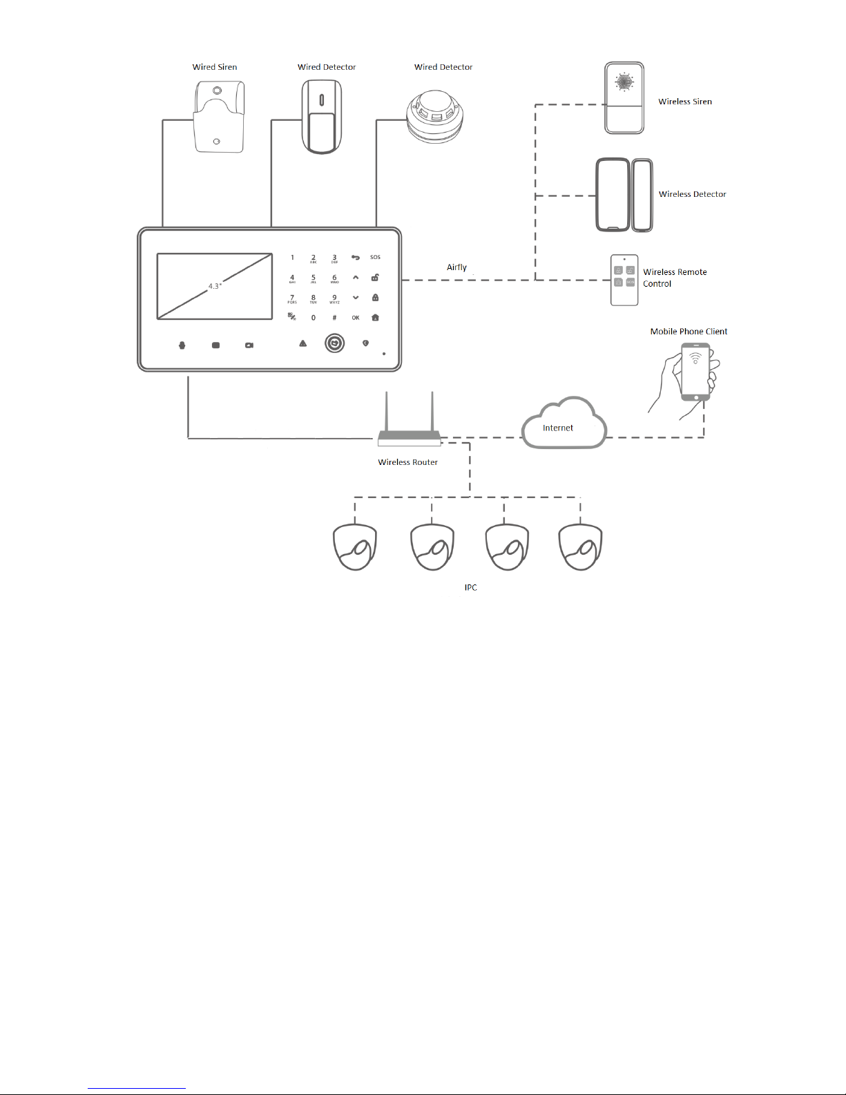
1.3 Typical Network
Video alarm control panel combines with IPC, detector, siren, APP and alarm center, and thus
forms an omnidirectional arm and disarm alarm system, as shown in Figure 1-1.
Page 11
2
Figure 1-1
Page 12
3
2 Device Structure
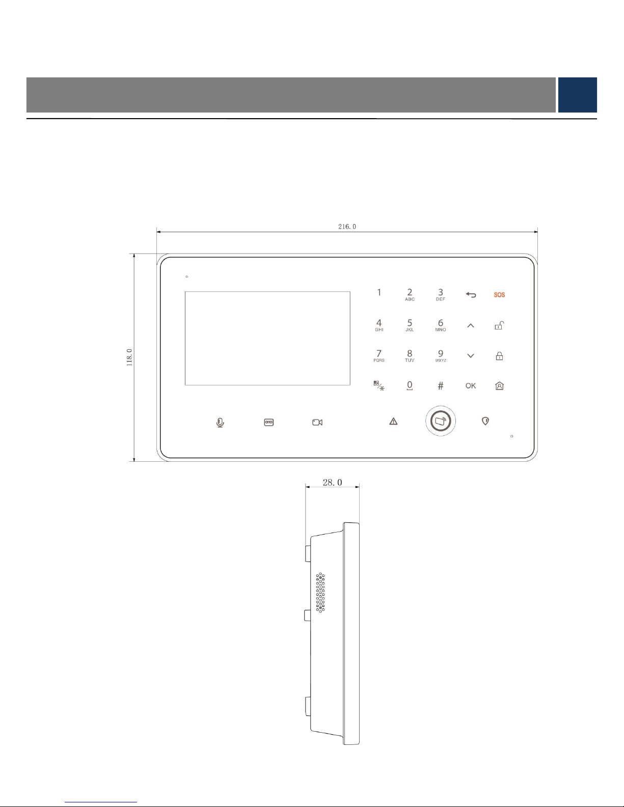
2.1 Structure Dimension
External dimension of the device is shown in Figure 2-1 and
Figure 2-2. The unit is mm.
Figure 2-1
Page 13
4
Figure 2-2
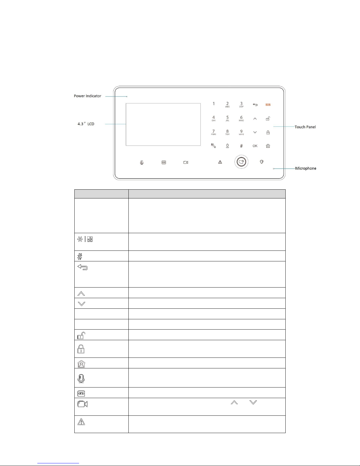
2.2 Front Panel
Front panel is shown in Figure 2-3. For keys and icons, please refer to Table 2-1.
Figure 2-3
Key or Icon
Description
0~9
A~Z
Enter number 0~9, page up/down.
Enter English letters A~Z and a~z.
In homepage, press [1] to customize arm quickly; press [2]
to view failure alarm info; press [3] to view zone alarm info.
Return to homepage.
Switch the input method.
Enter point (.).
Return to previous menu.
Delete info.
Exit recording playback/video preview interface.
Move up.
Move down.
OK
Confirm.
SOS
Press this key for 3s, to give an emergency alarm.
Disarm.
Away arm.
Stay arm.
Long press it to record audio, up to 30s each time. Save it
in system.
Press it once, to play the last recording.
Press it to preview video. Then, press [ ] or [ ] to switch
the channel.
The indicator turns on in case of detector offline or main
power off.
Page 14
5
Key or Icon
Description
Red light on during arm.
Away arm and disarm by swiping a registered card.
Red light on when there is an alarm.
Table 2-1
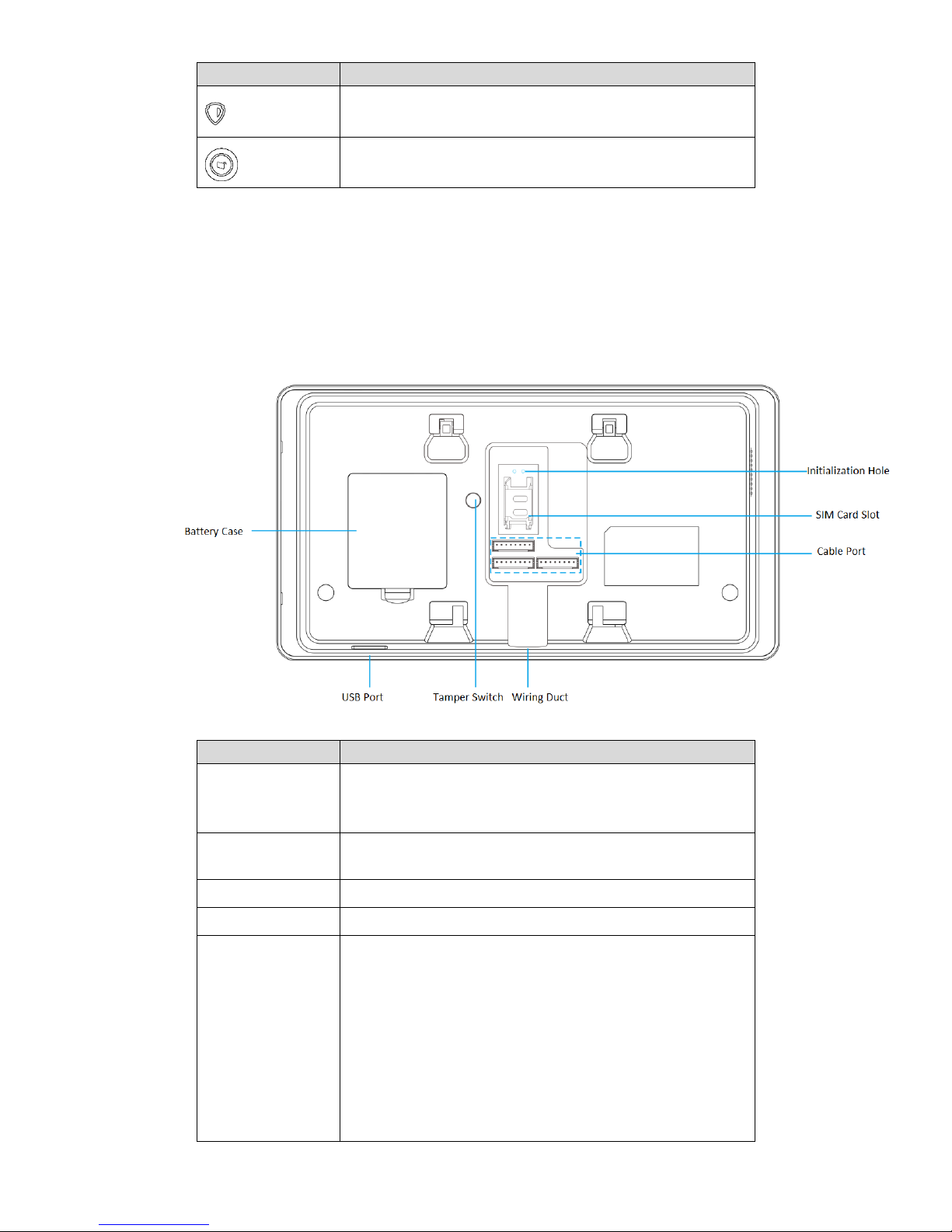
2.3 Rear Panel
Rear panel includes battery box and all kinds of ports, as shown in Figure 2-4. Please refer to
Table 2-2 for details.
Figure 2-4
Port/slot
Description
Battery Case
Install 1900mAh battery; provide emergency power when
12V power supply fails. Please refer to “3.3 Battery
Installation” for details.
USB Port
USB port connects storage device to backup linkage video
in event info.
Tamper Switch
Prevent individuals from dismantling the device.
Wiring Duct
After arrangement, cables go out of wiring duct.
Cable Port
Please refer to Figure 2-5 for mark of every pin. Detailed
descriptions are as follows:
PWR: 12V power input port.
AUX: 12V auxiliary power output.
GND: ground.
Z1/2: two-channel wired zone input.
RING-O/TIP-O: telephone line port.
NO/COM: 1-channel relay alarm output.
BELL: wired siren output.
Page 15
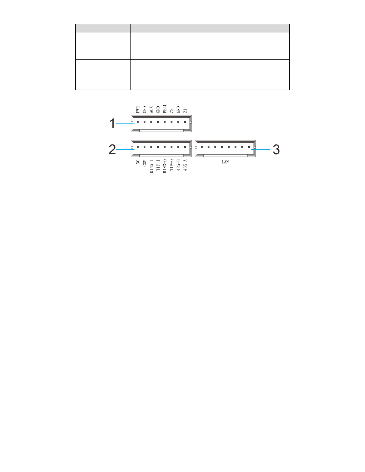
6
Port/slot
Description
RING-I/TIP-I: telephone port.
485-A/485-B: 485 device port.
LAN: network port.
SIM Card Slot
Support SIM cards of local operators.
Initialization Hole
Insert both ends of the cable into two holes for about 5s, so
as to restore factory settings.
Table 2-2
Figure 2-5
Page 16
7
3 Installation
3.1 SD Card Installation
This device is able to install maximum 128G SD card, in order to save alarm recordings.
Step 1 Open battery cover and take out the battery.
Step 2 Push SD card into the slot in accordance with arrow direction in Figure 3-1.
SD card can only be installed and dismantled when the power is off. To dismantle SD card,
press it inward a bit, so SD card will pop up slightly and can be taken out with a tool.
Figure 3-1
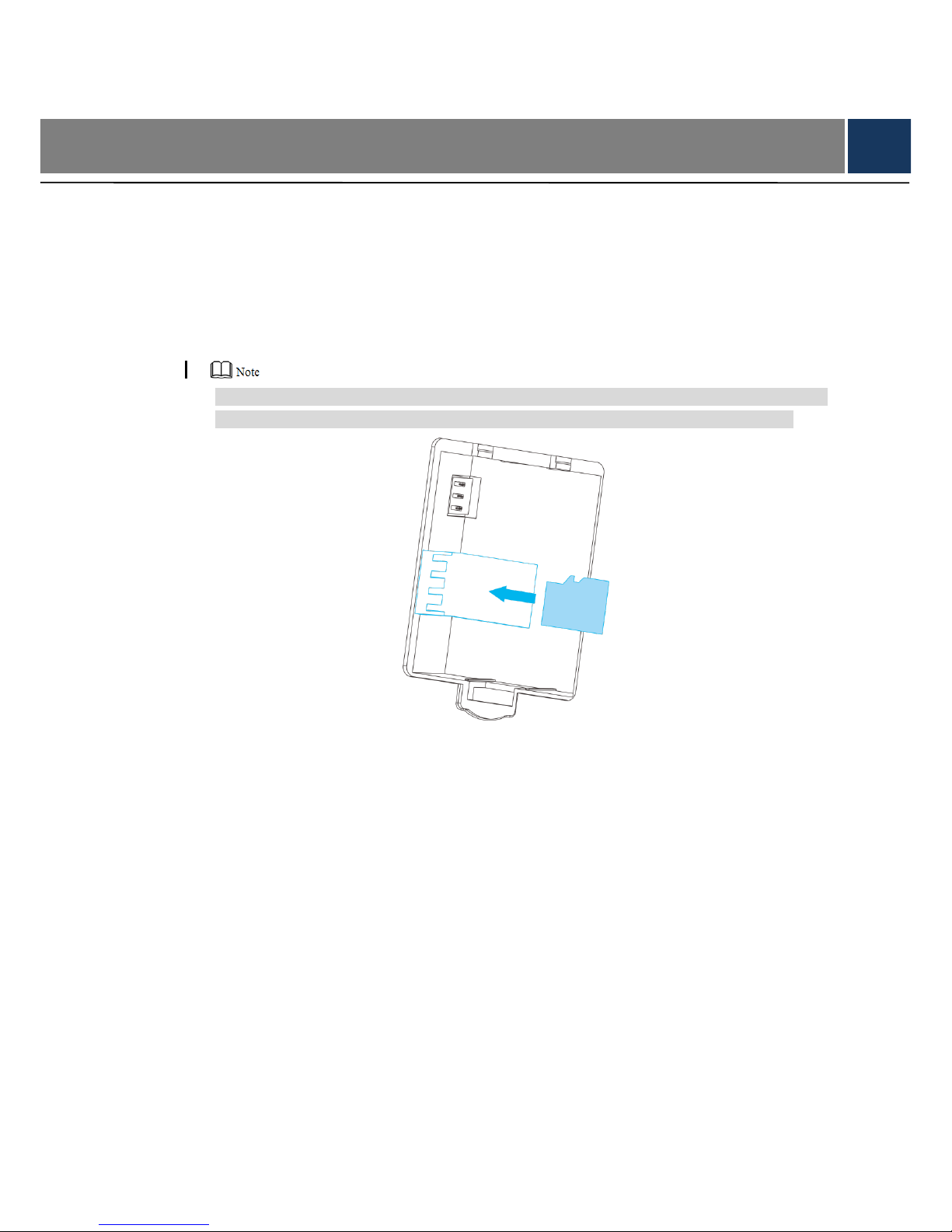
3.2 SIM Card Installation
This device supports SIM card, in order to report alarm and fault events through short message.
Step 1 Push slot cover toward cable port, flip it up and open the slot cover.
Step 2 Insert SIM card into the slot in accordance with arrow direction in Figure 3-2.
Step 3 Put back slot cover, and push it forward to fix SIM card.
Page 17

8
Figure 3-2
3.3 Battery Installation
This device installs 1900mAh lithium battery, provides emergency power when 12V power
supply fails and thus ensures its normal operation. The device will be rebooted 3 minutes after
12V power supply is connected again, so as to ensure normal use of all functions.
Power supply of lithium battery is as follows:
Some modules with relatively high power consumption cannot work normally, including
IC/ID card(arm and disarm is only realized by touching the keys), USB HUB (WIFI and
USB disk), local 1-channel relay alarm output, RS485 communications, voice input, audio
output, local 12V auxiliary power and siren output.
Key backlight becomes dark.
Step 1 Put the battery into battery box in accordance with arrow direction in Figure 3-3.
Step 2 Close the cover in accordance with arrow direction in the figure.
Page 18

9
Figure 3-3
3.4 Cable Installation
This device provides cable port to connect 12V power, wired detector, wired siren, wired
telephone and alarm output device.
Step 1 Insert cable into corresponding pin header socket.
Step 2 Neaten all cables and lead them out of the wiring duct.
Figure 3-4
3.5 Panel Installation
This device adopts wall installation. According to different scenes, it consists of 86 box
installation and non-86 box installation.
3.5.1 86 Box Installation
Step 1 Lock installation bracket at fixing hole of 86 box with screw A, so as to fix bracket on
the wall.
Step 2 Hang the device on the hook of installation bracket in accordance with arrow direction
in Figure 3-5.
Page 19

10
Figure 3-5
3.5.2 Non-86 Box Installation
Step 1 Open holes on wall in accordance with position of screw B of bracket, and embed
expansion bolts.
Step 2 Fix installation bracket directly on wall with screw B.
Step 3 Hang the device on the hook of installation bracket in accordance with arrow direction
in Figure 3-6.
Figure 3-6
Page 20

11
4 Operation Instruction
4.1 Password Setting
4.1.1 First Login
For security reason, please set password at first time login, as shown in Figure 4-1.
Figure 4-1
Step 1 Press [ ] or [ ] to select text box, and press numeric key to input “Password” and
“Confirm”.
In case of wrong input, press [ ], or press [ ] or [ ], select “Clear” to clear the
inputted content and input again.
Step 2 Press [ ] or [ ] to select “Save”. Then, press [OK] to enter the homepage.
4.1.2 Not First Login
After login, modify password in “System→ Password”.
Step 1 In the homepage, press [ ] or [ ], select “System” and press [OK].
Step 2 Press [ ] or [ ], select “Password” and press [OK].
The interface is shown in Figure 4-2.
Page 21

12
Figure 4-2
Step 3 Press [ ] or [ ], select the text box, and press numeric keys to enter “Old
Password”, “New Password” and “Confirm”.
New password shall not be the same as old password.
Step 4 Press [ ] or [ ], select “Save” and press [OK] to save the settings.
4.2 Homepage Introduction
Enter the homepage after the password is modified during the first login. If it is not the first login,
display “Welcome” progress bar after start and then display the homepage, as shown in Figure
4-3. For details, please refer to Table 4-1.
Figure 4-3
Page 22

13
Symbol
Description
Mobile signal strength symbol of SIM card, representing that SIM
card has been installed.
WIFI network symbol, representing that WIFI connection is enabled.
The system is in disarm status. It displays in arm status.
USB symbol, representing a USB has been inserted.
System is disarmed. Armed system shows .
SD card symbol, representing a SD card has been installed.
The device supports battery power supply. When main power and
battery co-exist and the battery is not full, the battery will be
charged. The interface displays battery symbol and electric quantity
percentage.
Display current system time at the homepage and status bar, such
as 18:28.
Display current system time.
It represents that voice messages are not read. Please press [ ] to
play.
Search and view event info; backup the linkage videos in the events.
Realize the following functions:
Zone: Set zone.
Mode: Set the arm mode of the zone; realize uniform arm and
disarm.
Wireless enrollment: Pairing connection between wireless
detectors and panel.
Camera: Manage IPC.
PGM: Program output setting. Set active time of wired output,
siren and internal siren when alarm is triggered.
RFID: Add RFID card, arm and disarm with the card.
Others: Set alarm uploading method (SMS or PSTN) when
SOS, main power off and tamper switch are triggered.
Realize the following functions:
Password: Modify user password, supporting numbers with 4~8
digits.
Info: View log info, device version and serial number.
Time: Set device time, time format and DST.
SD card: View SD card capacity or format.
Network: Set network connection of the device, including wired,
Page 23

14
Symbol
Description
WIFI, 2G and P2P.
Others: Set time delay, exit/ screen lock time, volume and key
tone.
Initialization: reboot the device or restore factory setting.
Alarm center: Set alarm center info, supporting 2 groups of
alarm center.
Table 4-1
4.3 Network Setting
4.3.1 Wired Network
The device supports wired network connection.
Step 1 In the homepage, press [ ] or [ ], select “System” and press [OK].
Step 2 Press [ ] or [ ], select “Network” and press [OK].
Step 3 Press [ ] or [ ], select “Net” and press [OK].
The interface is shown in Figure 4-4.
Figure 4-4
Step 4 Press [ ] or [ ], select the text box, and press numeric keys to enter new address
field info.
Repeat the operation to modify “IP Address”, “Subnet Mask”, “Default Gateway”,
“DNS1” and “DNS2”.
If “DHCP” is ticked, it is unnecessary to configure IP address and relevant info,
because the system obtains IP info dynamically.
Step 5 Press [ ] or [ ], select “Save” and press [OK] to save the settings.
Page 24

15
4.3.2 WIFI
The device supports WIFI network connection.
Step 1 In the homepage, press [ ] or [ ], select “System” and press [OK].
Step 2 Press [ ] or [ ], select “Network” and press [OK].
Step 3 Press [ ] or [ ], select “WIFI” and press [OK].
The interface is shown in Figure 4-5.
Figure 4-5
Step 4 Press [ ] or [ ], select and press [OK].
Switch to and enable WIFI function.
Step 5 Press [ ] or [ ], select “Search” and press [OK].
Search and display nearby available WIFI info, as shown in Figure 4-6.
Figure 4-6
Step 6 Press [ ] or [ ], select needed WIFI and press [OK] to input password. Start
connection.
If the interface displays WIFI info as shown in Figure 4-7, it means that the connection
is successful. If it displays “Not Connected”, it means that connection has failed. Please
Page 25

16
search and connect again.
Pairing function is used when the device connects WIFI network, with which
mobile phone APP is connected. When mobile phone APP inputs WIFI password
to connect, the device chooses “Pairing” to connect this WIFI network. For details,
please refer to user’s manual of mobile phone APP.
For password input operation, please refer to “Appendix 1 Operating Instructions
of Input Method”.
Figure 4-7
4.3.3 2G
Support SIM card; report alarm and failure events through SMS (short message service).
2G function shall be enabled to realize SMS alarm.
Step 1 In the homepage, press [ ] or [ ], select “System” and press [OK].
Step 2 Press [ ] or [ ], select “Network” and press [OK].
Step 3 Press [ ] or [ ], select “2G” and press [OK].
The interface is shown in Figure 4-8.
Page 26

17
Figure 4-8
Step 4 Press [ ] or [ ], select and press [OK].
Switch to and enable 2G function.
Step 5 Press [ ] or [ ], select “SMS Title” text box and press [OK].
Please refer to “Appendix 1 Operating Instructions of Input Method”, input SMS title
info, which is used to differentiate from SMS contents.
Step 6 Press [ ] or [ ], select “Contacts” text box and press [OK]. Input a receiver’s phone
number and press [OK]. Press [ ] or [ ] again, select and press [OK], to add
the phone number to the list.
Repeat above steps to input other phone numbers, as shown in Figure 4-9.
Figure 4-9
Step 7 Press [ ] or [ ], select “Save” and press [OK] to save the settings.
4.3.4 P2P
Enable P2P function, open mobile phone APP, directly input the SN or scan QR code to get SN,
Page 27

18
save setting and then you can arm/disarm on APP to manage more than one device.
Step 1 In the homepage, press [ ] or [ ], select “System” and press [OK].
Step 2 Press [ ] or [ ], select “Network” and press [OK].
Step 3 Press [ ] or [ ], select “P2P” and press [OK].
The interface is shown in Figure 4-10.
Figure 4-10
Step 4 Press [OK] to enable or disenable P2P function, as shown in Figure 4-11. After
enabling P2P function, you can scan QR code with APP or directly enter SN to add
device and access management device. Please refer to relevant user’s manual for
details.
Figure 4-11
4.4 Wireless Enrollment
Add and delete wireless detectors, wireless sirens, wireless remote controls and wireless panic
buttons.
Page 28

19
4.4.1 Add Wireless Device
Step 1 In the homepage, press [ ] or [ ], select “Setting”, then select “Enroll” and press
[OK].
The interface is shown in Figure 4-12.
Figure 4-12
Step 2 Press [ ] or [ ], select and press [OK].
Switch to to enable wireless enrollment function to enter enrolling status. The
interface displays “Wireless Enrolling…”, as shown in Figure 4-13.
Figure 4-13
Step 3 Enrollment ways between wireless devices and panel refers to the following
introductions for details.
Wireless detector/siren/panic button enrollment
Power on the detector/siren/panic button. Its indicator light is normally on and then
flashes fast, representing that it enters enrollment mode and starts enrollment.
Enrollment success: detector/siren/panic button info is displayed on LCD screen.
Enrollment failure: detector/siren/panic button’s red light flashes slowly for 3 times.
Page 29

20
Repeat above steps, until it is paired successfully. Alternatively, slide the
tamperproof switch of the case manually to make red light flash fast until it is
paired successfully.
● Zone no. of wireless detector starts from 3 in sequence.
● Zone no. of wireless siren starts from 44 in sequence.
● Zone no. of wireless panic button starts from 35 in sequence.
Taking “wireless PIR detector” for example, position of shell tamper switch is
shown in Figure 4-14.
Figure 4-14
Remote control enrollment
Press any key for 3s. If this remote control info is displayed on LCD screen, it
means that enrollment is successful; otherwise, enrollment has failed; please
enroll again.
Channel no. of wireless remote control starts from 35 in sequence.
4.4.2 Delete Wireless Device
Step 1 In the homepage, press [ ] or [ ], select “Setting” and press [OK].
Step 2 Press [ ] or [ ], select “Enroll” and press [OK].
The interface is shown in Figure 4-15.
Page 30

21
Figure 4-15
Step 3 Press [ ] or [ ], select in the corresponding wireless device column, and press
[OK]. “Confirm” prompt box will pop up.
Step 4 Press [ ] or [ ], select “Yes” and press [OK] to delete it.
4.5 Camera Management
Add and delete remote IP camera.
4.5.1 Add Camera
Step 1 In the homepage, press [ ] or [ ], select “Setting” and press [OK].
Step 2 Press [ ] or [ ], select “Camera” and press [OK].
The interface is shown in Figure 4-16. Add cameras in two ways as follows.
Red means that the camera is offline.
Page 31

22
Figure 4-16
Search
Press [ ] or [ ], select and press [OK]. 1.
Search the info about all cameras in the same network segment, as shown in
Figure 4-17. Press corresponding numeric key to page up and down.
Figure 4-17
Press [ ] or [ ], select a camera and press [OK]. 2.
Add the camera, as shown in Figure 4-18.
Figure 4-18
Manual adding
Press [ ] or [ ], select and press [OK]. 1.
The interface is shown in Figure 4-19.
Page 32

23
Figure 4-19
Press [ ] or [ ], select corresponding parameter text box, input numbers, or 2.
input them by reference to “Appendix 1 Operating Instructions of Input Method”.
For specific parameter descriptions, please refer to Table 4-2.
Parameter
Description
Channel
The system identifies idle channel number automatically,
which cannot be modified.
Rstp Port
Input RTSP port number of the camera. It is 554 by
default.
Http Port
Input HTTP communications port number of the camera.
It is 80 by default.
TCP Port
It is service port of TCP protocol, to be set according to
the user’s actual needs. It is 37777 by default.
IP Address
Input IP address of the camera.
Username/
Password
Input username and password to login the camera.
Protocol
Select from Private and Onvif according to actual
conditions. Press [OK] to switch.
Pre-record
Pre-record time before linkage alarm recording.
At most 2 cameras can enable pre-record function.
Table 4-2
Press [ ] or [ ], select “Save” and press [OK] to save the settings. 3.
4.5.2 Modify/View Camera Parameters
Step 1 In the homepage, press [ ] or [ ], select “Setting” and press [OK].
Step 2 Press [ ] or [ ], select “Camera” and press [OK].
Step 3 Press [ ] or [ ], select “Parameter” and press [OK].
Display connection info about this camera.
Step 4 Modify camera info by reference to manual adding description in “4.5.1 Add Camera”.
Page 33

24
4.5.3 Delete Camera
Step 1 In the homepage, press [ ] or [ ], select “Setting” and press [OK].
Step 2 Press [ ] or [ ], select “Camera” and press [OK].
Step 3 Press [ ] or [ ], select and press [OK]. Delete the corresponding camera.
4.6 RFID Management
Add and delete RFID card. After RFID card is added, you can use this card to away arm and
disarm.
4.6.1 Add RFID Card
Step 1 In the homepage, press [ ] or [ ], select “Setting” and press [OK].
Step 2 Press [ ] or [ ], select “RFID” and press [OK].
The interface is shown in Figure 4-20.
Figure 4-20
Step 3 Press [ ] or [ ], select and press [OK]. Enter card-swiping interface, as shown
in Figure 4-21.
Page 34

25
Figure 4-21
Step 4 Swipe FRID card in the card-swiping zone.
Display ID, representing successful identification. Then, press [ ] or [ ], select
“Name” text box and press [OK] to enter card name.
Step 5 Press [ ] or [ ], select “Save” and press [OK] to save the settings.
4.6.2 Delete RFID Card
Step 1 In the homepage, press [ ] or [ ], select “Setting” and press [OK].
Step 2 Press [ ] or [ ], select “RFID” and press [OK].
Step 3 Press [ ] or [ ], select and press [OK] to delete this RFID card.
4.7 Zone Setting
Set zone name and linkage parameters during alarm.
Step 1 In the homepage, press [ ] or [ ], select “Setting” and press [OK].
Step 2 Press [ ] or [ ], select “Zone” and press [OK].
The interface is shown in Figure 4-22.
Page 35

26
Figure 4-22
Step 3 Press [ ] or [ ], select a zone to be set and press [OK].
The interface is shown in Figure 4-23.
Figure 4-23
Step 4 Press [ ] or [ ], select parameters and press [OK] to select or modify.
For specific parameter descriptions, please refer to Table 4-3.
Parameter
Description
Name
Set zone name, which will be shown in linkage SMS in case of alarm
linkage. For specific settings, please refer to “Appendix 1 Operating
Instructions of Input Method”.
Zone No.
It is identified automatically and cannot be set.
Alarm Out
After selection, output a linkage alarm when an alarm is triggered in
the zone.
Internal
Siren
After selection, internal siren will send sound when an alarm is
triggered in the zone.
Siren
After selection, siren will send an alarm when an alarm is triggered in
the zone.
SMS
After selection, alarm info will be sent by SMS when an alarm is
triggered in the zone.
Page 36

27
Parameter
Description
PSTN
Two check boxes represent PSTN 1 and PSTN 2 respectively.
After selection, alarm info will be reported to the selected PSTN when
an alarm is triggered in the zone.
Record
Channel
Four check boxes represent record channel 1~ 4.
After selection, the selected channel will start recording when an
alarm is triggered in the zone.
Record
Time
Press numeric key to input record time.
After setting record time, videos will be recorded within the time period
when alarm is triggered.
Table 4-3
Step 5 Press [ ] or [ ], select “Save” and press [OK] to save the settings.
4.8 Mode Setting
The system provides 3 modes, including stay, away and custom. Add required zone to
corresponding mode; realize uniform arm and disarm.
Stay: add zones around the house to “Stay” mode; enable “Stay” mode when you are at
home.
Away: add all zones to “Away” mode; enable “Away” mode when you are out. It includes
exit time and entry delay. Please refer to Table 4-5 for details.
Custom: add required zones to “Custom” mode; enable “Custom” mode in due time.
For example, add 3 zones to “Stay” mode.
Step 1 In the homepage, press [ ] or [ ], select “Setting” and press [OK].
Step 2 Press [ ] or [ ], select “Mode” and press [OK].
The interface is shown in Figure 4-24.
Figure 4-24
Step 3 Press [ ] or [ ], select “Stay” and press [OK].
The interface is shown in Figure 4-25.
Page 37

28
Figure 4-25
Step 4 Press [ ] or [ ], press [OK] and select the zones.
Repeat the operation to select multiple zones.
One zone can be added to different modes.
Step 5 Press [ ] or [ ], select “Save” and press [OK] to save the settings.
4.9 PGM Setting
Set alarm output time, siren time and internal siren time.
Step 1 In the homepage, press [ ] or [ ], select “Setting” and press [OK].
Step 2 Press [ ] or [ ], select “PGM” and press [OK].
The interface is shown in Figure 4-26.
Figure 4-26
Step 3 Press [ ] or [ ]; select corresponding parameter text box.
Step 4 Press numeric keys to input time value.
Step 5 Press [ ] or [ ], select “Save” and press [OK] to save the settings.
Page 38

29
4.10 Event Reporting Setting
Set reporting position of alarm info in case of SOS, power off and tamper.
Step 1 In the homepage, press [ ] or [ ], select “Setting” and press [OK].
Step 2 Press [ ] or [ ], select “Other” and press [OK].
The interface is shown in Figure 4-27.
Figure 4-27
Step 3 Press [ ] or [ ], select corresponding check box and press [OK] to select or cancel.
Step 4 Press [ ] or [ ], select “Save” and press [OK] to save the settings.
4.11 Time Setting
Set device time, time format and DST.
4.11.1 Time Setting
Step 1 In the homepage, press [ ] or [ ], select “System” and press [OK].
Step 2 Press [ ] or [ ], select “Time” and press [OK].
Step 3 Press [ ] or [ ], select “Time Setting” and press [OK].
The interface is shown in Figure 4-28.
Page 39

30
Figure 4-28
Step 4 Press [ ] or [ ], select Year/Month/Day/Hour/Minute/Second text box, and press
numeric keys to input numbers.
Step 5 Press [ ] or [ ], select “Save” and press [OK] to save the settings.
4.11.2 DST Setting
Step 1 In the homepage, press [ ] or [ ], select “System” and press [OK].
Step 2 Press [ ] or [ ], select “Time” and press [OK].
Step 3 Press [ ] or [ ], select “DST” and press [OK].
The interface is shown in Figure 4-29.
Figure 4-29
Step 4 Press [ ] or [ ]; select .
Switch to and start DST function.
Step 5 Press [ ] or [ ], select Month/Day/Hour/Minute text box, and press numeric keys to
input numbers.
Set DST start time and end time. The device will operate according to DST within this
Page 40

31
time period.
Step 6 Press [ ] or [ ], select “Save” and press [OK] to save the settings.
4.11.3 Time Format
Step 1 In the homepage, press [ ] or [ ], select “System” and press [OK].
Step 2 Press [ ] or [ ], select “Time” and press [OK].
Step 3 Press [ ] or [ ], select “Time Format” and press [OK].
The interface is shown in Figure 4-30.
Figure 4-30
Step 4 Press [ ] or [ ], select corresponding check box and press [OK] to switch format.
For specific parameter descriptions, please refer to Table 4-4.
Parameter
Description
Date Format
It includes yyyy MM dd, MM dd yyyy and dd MM yyyy.
yyyy represents year, MM represents month and dd
represents day.
Separator
It includes “-”, “.” and “/”.
Time Zone
Please set according to local time zone.
Table 4-4
Step 5 Press [ ] or [ ], select “Save” and press [OK] to save the settings.
4.12 Call Center Setting
Set 2 groups of call center info. After setting telephone number of call center, alarms will be
reported to call center.
Step 1 In the homepage, press [ ] or [ ], select “System” and press [OK].
Step 2 Press [ ] or [ ], select “Call Center” and press [OK].
The interface is shown in Figure 4-31.
Page 41

32
Figure 4-31
Step 3 Press [ ] or [ ], select “Call Group” text box and press [OK].
Switch between Call Center 1 and Call Center 2. Taking “1” for example, it means to
view or set Call Center 1.
Step 4 Press [ ] or [ ], select other parameter text boxes, input with input method or
numeric keys, and thus set “Name”, “Number” and “User Code” of this call center.
For operation, please refer to “Appendix 1 Operating Instructions of Input
Method”.
Set actual user code of call center.
“Clear” is used to delete alarm events that exist in the system but are not sent yet.
Step 5 Press [ ] or [ ], select “Save” and press [OK] to save the settings.
4.13 Delay and Volume Setting
Step 1 In the homepage, press [ ] or [ ], select “System” and press [OK].
Step 2 Press [ ] or [ ], select “Other” and press [OK].
The interface is shown in Figure 4-32.
Page 42

33
Figure 4-32
Step 3 Press [ ] or [ ], select corresponding parameter text boxes, and press numeric
keys to input time value.
For introduction to every parameter, please refer to Table 4-5.
Key tone is selected by pressing [OK].
Parameter
Description
Enter
Delay
If away arm is chosen and “Enter Delay” is set, the system
won’t report alarms if you disarm within “Enter Delay” time.
Exit Delay
If “Exit Delay” is set, the system won’t report alarms if you
leave the zone within countdown of “Exit Delay” time.
Screen
Lock
Screen-on time when there is no operation. After screen
lock, press any key to wake it up.
Volume
Adjust volume of siren and internal siren.
Tone
Turn on or turn off the tone of touching the keys.
Table 4-5
Step 4 Press [ ] or [ ], select “Save” and press [OK] to save the settings.
4.14 SD Card Format
Please format SD card during the first use.
Step 1 In the homepage, press [ ] or [ ], select “System” and press [OK].
Step 2 Press [ ] or [ ], select “SD” and press [OK].
The interface is shown in Figure 4-33。
Figure 4-33
Step 3 Press [OK]. Pop up a confirmation prompt box.
Step 4 Press [ ] or [ ], select “Yes” and press [OK].
It will display “Successful Format”. In case that it displays failure, please format it
Page 43

34
again.
4.15 Initialization
Reboot the device or restore factory defaults.
4.15.1 Reboot
Step 1 In the homepage, press [ ] or [ ], select “System” and press [OK].
Step 2 Press [ ] or [ ], select “Initialization” and press [OK].
Step 3 Press [ ] or [ ], select “Reboot” and press [OK]. Pop up a confirmation prompt box.
Step 4 Press [ ] or [ ], select “Yes” and press [OK]. The device will be rebooted.
4.15.2 Initialization
Step 1 In the homepage, press [ ] or [ ], select “System” and press [OK].
Step 2 Press [ ] or [ ], select “Initialization” and press [OK].
Step 3 Press [ ] or [ ], select “Initialization” and press [OK].
Pop up a confirmation prompt box.
Step 4 Press [ ] or [ ], select “Yes” and press [OK].
It displays “Rebooting…” The device will be rebooted and restore factory defaults.
4.16 Info
View device log and info.
4.16.1 View Device Log
Step 1 In the homepage, press [ ] or [ ], select “System” and press [OK].
Step 2 Press [ ] or [ ], select “Info” and press [OK].
Step 3 Press [ ] or [ ], select “Log” and press [OK].
The interface is shown in Figure 4-34.
Page 44

35
Figure 4-34
The last 45 log info is displayed. Press numeric keys to page up and down.
is used to delete all logs.
Step 4 Press [ ] or [ ], and select .
The interface is shown in Figure 4-35. Press [ ] or [ ], select text box and press
numeric keys to input numbers. Then, press [ ] or [ ], select “Search” to display the
last 45 logs within the stipulated time period.
Figure 4-35
Step 5 Press [ ] or [ ], select a log and press [OK] to view detailed info.
4.16.2 View Version Info
Step 1 In the homepage, press [ ] or [ ], select “System” and press [OK].
Step 2 Press [ ] or [ ], select “Info” and press [OK].
Step 3 Press [ ] or [ ], select “Version Info” and press [OK].
View software version, serial number and version date. The interface is shown in
Page 45

36
Figure 4-36.
Figure 4-36
4.17 Event
Search and view events; backup linkage videos of the events.
4.17.1 Search and View Events
Step 1 In the homepage, press [ ] or [ ], select “Event” and press [OK].
The interface is shown in Figure 4-37.
Figure 4-37
Display the last 45 events; press numeric keys to page up and down.
Step 2 Press [ ] or [ ], and select .
The interface is shown in Figure 4-38. Press [ ] or [ ], select text box and press
Page 46

37
numeric keys to input numbers. Then, press [ ] or [ ], select “Search” to display the
last 45 events within the stipulated time period.
Figure 4-38
Step 3 Press [ ] or [ ], select an event and press [OK] to view detailed info.
4.17.2 Play Record
If SD card has been installed and alarm linkage record has been set, after an alarm event, the
record can be played at detailed info interface.
Step 1 Enter “Detailed Info” interface according to viewing steps, as shown in Figure 4-39.
Figure 4-39
Step 2 Press [ ] or [ ], select record channel and press [OK] to select it.
Step 3 Press [ ] or [ ], select “Play” and press [OK] to play and preview the record.
4.17.3 Backup Video
Backup the linkage record videos of the events. Before operation, please complete the
following two items:
Page 47

38
With search function, search event info that needs to backup videos.
Insert USB disk.
Step 1 At event interface, press [ ] or [ ], select and press [OK]
Step 2 Press [ ] or [ ], select an event and press [OK] to select it.
Repeat the operation and select multiple events.
Step 3 Press [ ] or [ ], select and press [OK].
Pop up a confirmation prompt box.
Step 4 Press [ ] or [ ], select “Yes” and press [OK]. Linkage record videos of the selected
events will backup in the USB disk.
4.18 Arm and Disarm
4.18.1 Arm and Disarm with Shortcut Keys
The system provides shortcut keys for stay arm, away arm, custom arm, disarm and etc.
Before arm, please make sure the zone you intend to arm has been added to corresponding
arm mode.
4.18.1.1 Stay Arm
Step 1 Press [ ] and password input box will pop up.
Step 2 Press numeric keys to input password.
Step 3 Press [OK]. The system beeps once, and status bar at the top of LCD screen displays
“Arm”, so zone of “Stay Arm” mode enters armed status.
Figure 4-40
Page 48

39
4.18.1.2 Away Arm
Step 1 Press [ ] and password input box will pop up.
Step 2 Press numeric keys to input password.
Step 3 Press [OK]. The system beeps all along, and enters exit delay countdown. Status bar
at the top of LCD screen displays “Arm”, so zone of “Away Arm” mode enters armed
status. Exit the zone within countdown, and the system won’t upload the alarm.
Figure 4-41
4.18.1.3 Custom Arm
Step 1 Press [1] and password input box will pop up.
Step 2 Press numeric keys to input password.
Step 3 Press [OK]. The system beeps once, and status bar at the top of LCD screen displays
“Arm”, so zone of “Custom Arm” mode enters armed status.
Figure 4-42
Page 49

40
4.18.1.4 Disarm
Step 1 Press [ ] and password input box will pop up.
Step 2 Press numeric keys to input password.
Step 3 Press [OK]. The system beeps twice, and status bar at the top of LCD screen displays
“Disarm” to remove the last arm, so all zones enter disarmed status.
Figure 4-43
4.18.2 Arm and Disarm with Card
The system supports to arm and disarm by swiping card, but it is only valid for zones in “away
arm” mode.
Before arming, make sure that all designated zones are in “away arm” mode.
4.18.2.1 Arm
In disarmed status, swipe a card at card-swiping area. The system beeps all along, and enters
exit delay countdown, LCD shows “Arm” at the top; zones with “away arm” mode enter armed
status. Exit zones before countdown ends, which will not trigger alarm.
Page 50

41
Figure 4-44
4.18.2.2 Disarm
In armed status, swipe a card at card-swiping area. The system beeps twice, and LCD shows
“Disarm” at the top. Remove the last arm, and all zones enter disarmed status.
4.18.3 Arm and Disarm with Remote Control
The system supports to arm and disarm with remote control, so you can perform stay arm,
away arm, disarm and SOS remotely.
Before arming, make sure that all designated zones are in corresponding armed mode.
Figure 4-45
Page 51

42
4.18.4 Arm and Disarm with Mobile Phone APP
The system supports to arm and disarm with mobile phone APP. For specific operation, please
refer to user’s manual of mobile phone APP.
4.19 Duress Password
The device supports duress password. When you enter duress password, the system will
produce duress event alarm, and report alarm info with default linkage SMS and PSTN, which
won’t produce a log.
A duress password is to add “1” to the last digit of user password. If the last digit is “9”, enter “0”
as the last digit. For example, if a user password is “123456”, so its corresponding duress
password is “123457”. If a user password is “123459”, then its corresponding duress password
is “123450”.
4.20 View Zone Alarm Info
Press [3] in the homepage, and “Zone” interface will pop up, as shown in Figure 4-46.
means that the zone is in alarm status; means that the zone is in abnormal status;
means that the zone is in offline status.
In case of zone alarm in armed status, “Zone” interface will pop up automatically, so as to view
zone info.
Figure 4-46
Page 52

43
4.21 Sound Recording and Playback
4.21.1 Sound Recording
Press [ ] to record sound, at most 30s each time. Save it in system.
4.21.2 Playback
Press [ ] to play the last recording.
4.22 Video Preview
Press [ ] to preview video in the recording channel, press [ ] or [ ] to switch channels,
and press [ ] to exit the preview.
Page 53

44
Appendix 1 Operating Instructions of Input Method
During setting of some parameters, switch among English capital letter and small letter, number
and symbol. For example, modify zone name to be door12 in the following steps.
Step 1 At zone configuration interface, press [ ] or [ ], select name text box and press
[OK]. Input method will pop up, as shown in Figure 4-47.
Figure 4-47
Step 2 Press [ ] to switch to numeric input status, press numeric keys to input “12”, as
shown in Figure 4-48.
Figure 4-48
Step 3 Press [OK] to input info into the text box.
When pressing numeric keys to select, press [ ] or [ ] to page up and down, in case
that the required content doesn’t appear in the present page.
 Loading...