

Page 1
DAHLE
517
b
Abb.A
.y-2
,3a
Abb.B
1
-;
Abb.D
Page 2
BEDIENUNGSANLEITUNG
SCHNEIDEMASCHINE
SICHERHEITSSCHNEIDER,,DAHLE
,,DAHLE
5l T"
567"
Alle DAHLE-Schneidemaschinen
geprüft.
weise
Beachton
maschinon
Sicherhoitsoinrichtungen und
ständig horunterlallen
Wichtig: Vor
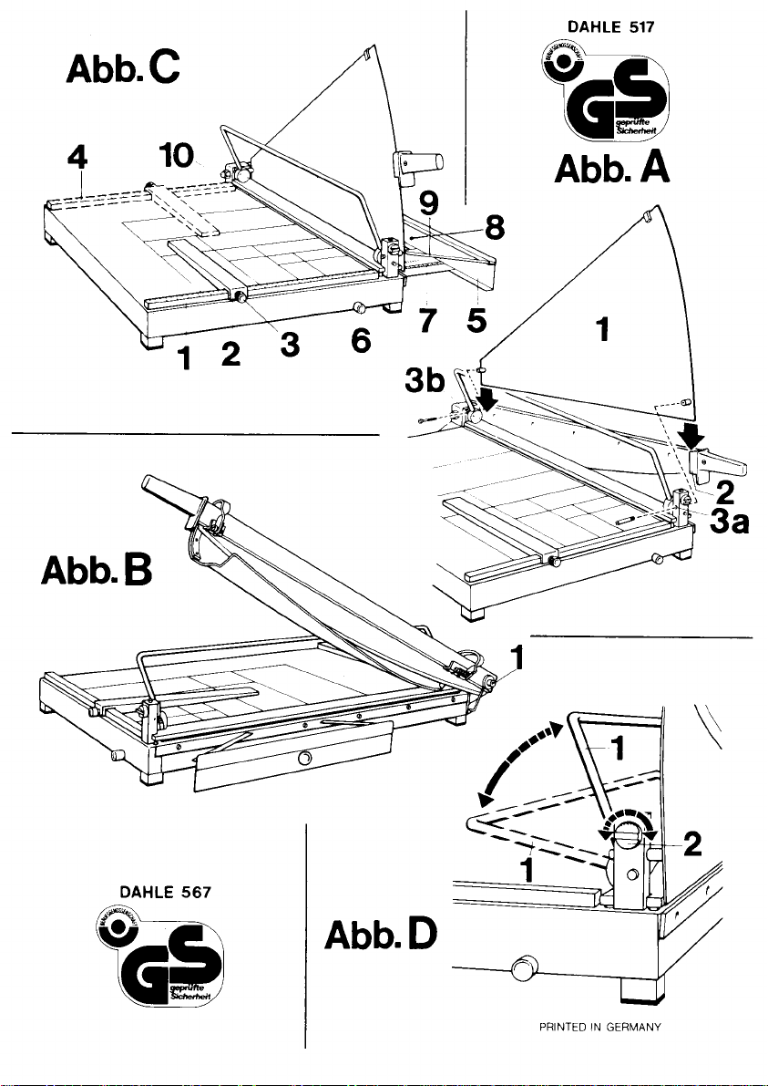
Montage
Der lose
Seite mit
Messeöalken
(Abb.
am
Bei der
fertig montiert
Die
1. Die Winkelanlage
2.
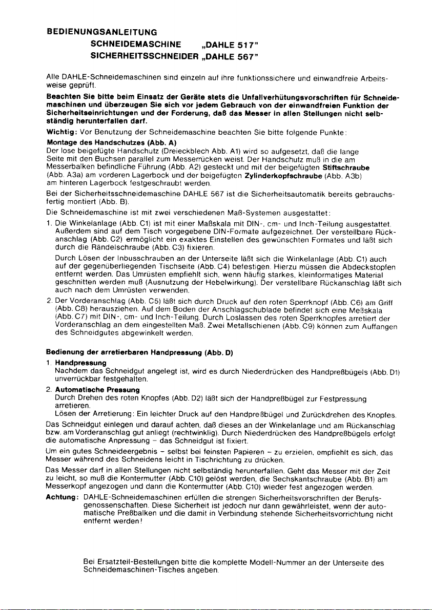
Bedienung
1. Handpressung
2.
Das
bzw. am Vorderanschlag
die automatische Anpressung
Um ein
Messer während
Das Messer
zu
Messerkopt
Achtung:
Si€ bitte beim Einsatz
und überzeugen
darl.
Benutzung der Schneidemaschine
des Handschutzes
beigefügte Handschutz
den Buchsen
befindliche Führung
A3a) am vorderen
hinteren
Lagerbock
Sicherheitsschneidemaschine DAHLE
Schneidemaschine ist mit zwei verschiedenen
Außerdem
anschlag
durch die Rändelschraube
Durch Lösen
auf der
entfernt werden. Das
geschnitten
auch
Der
(Abb.
(Abb.CZ)
Vorderanschlag
des
Nachdem
unverrückbar
Automatische Preasung
Durch
arretieren.
Lösen der Arretierung:
Schneidgut
leicht,
sind auf dem Tisch vorgegebene
(Abb.
gegenÜberliegenden
nach
dem Umrüsten verwenden.
Vo_rderanschlag
C8) herausziehen.
mit DIN-,
Schneidgutes
der
das
Drehen
gutes
Schneideergebnis
darf in
muß
so
angezogen
DAHLE-Schneidemaschinen
genossenschaften.
matische Preßbalken
entfernt
parallel
Lagerbock
festgeschraubt
(Abb.
B).
(Abb.Cl)
C2) ermöglicht
Inbusschrauben
der
werden
arretierbaren Handpressung (Abb.
Umrüsten
muß
(Abb.
cm- und Inch-Teilung.
an
dem eingestellten
abgewinkelt
Schneidgut
f estgehalten.
des roten Knopfes
einlegen und darauf
gut
des Schneidens leicht
allen Stellungen nicht
die Kontermutter
und dann die Kontermutter
werden !
srnd
einzeln auf
der
Goräte stets
Sie eich vor
der Forderung,
(Abb.
A)
(Dreieckblech
zum Messerrücken
(Abb.
und der
werden.
ist mit
einerMaßskala mit
ein exaktes Einstellen
(Abb.
C3)
an der
Tischseite
emptiehlt sich, wenn häufig
(Ausnutzung
C5) läßt
Auf
Ein leichter
anliegt
sich
dem Boden
werden.
angelegt ist, wird
(Abb.
Druck
achten,
(rechtwinklig).
-
das
Schneidgut ist lixiert.
-
selbst bei feinsten
(Abb.
Diese
erfüllen
Sicherheit ist
und die damit in
jedem
A2)
fixieren.
der Hebelwirkung).
durch Druck
Maß.
D2)
in Tischrichtung
selbständig herunterfallen.
C10)
ihre funktionssichere
die Untatlverhütungsvorschriften
Gebrauch
da8 dar Meaaer in
beachten
Abb. At) wird
weist. Der Handschutz
gesteckt
beigefügten Zylinderkopfschraube
567 ist die
DIN-Formate
Unterseite
(Abb.
C4) belestigen. Hierzu
der Anschlagschublade
Durch
Loslässen
Zwei Metallschienen (Abb.
D)
es durch Niederdrücken
läßt
sich der Handpreßbügel
auf den Handpreßbügel
daß dieses an
Durch Niederdrücken
gelöst
(Abb.
die
strengen Sicherheitsvorschriften
jedoch
Verbindung
yon
Sie bitte
so aufgesetzt,
und mit
der beigefügten
Sicherheitsautomatik
Maß-Systemen
DIN-,
aulgezeichnet. Der
gewünschten
des
läßt
sich
Der verstellbare
aui
den roten
des roten
der Winkelanlage
Papieren
zu
drücken.
werden,
die Sechskantschraube
C1O) wieder
nur
dann
stehende
und einwandfreie
der einwandlrei€n
allen Stellungen
folgende
daß die lange
muß in
ausgestattet:
cm- und
starkes, kleinformatiges
-
Inch-Teilung
Formates
Winkelanlage
die
müssen
Sperrknopf
befindet
zu erzielen,
gewährleistet,
siöh eine Meßskala
Sperrknopfes
C9) können
des Handpreßbügels
zur Festpressung
und Zurückdrehen
des Handpreßbügels
Geht das Messer mit
fest angezogen
Sicherheitsvorrichtung
Arbeits-
für
Schneide-
Funktion
nicht selb-
Punkte:
die am
Stiftschraube
(Abb.
A3b)
bereits oebrauchs-
ausgestattet.
verstellbare Rück-
die Abdeckstopfen
Rückanschlag
(Abb.
und
empfiehlt
läßt
und
(Abb.
C1) auch
Material
C6) am
arretiert
zum
Auffangen
des Knopfes.
am Rückanschlag
es sich,
der Zelt
(Abb.
B1)
werden.
der Berufs-
wenn
der auto-
der
sich
läßt
Griff
der
(Abb.
erlolgl
das
am
nicht
sich
D1)
Bei
Ersatzteil-Bestellungen
Schneidemaschinen-Tisches
bitte die komplette
anoeben.
Modell-Nummer
an der Unterseite
des
Page 3

OPERATING
GUILLOTINE
SAFETY
INSTRUCTIONS
GUILLOTINE
..DAHLE
..DAHLE 567"
517"
All DAHLE-guillotines
When
using the machines
guillotines,
for
knife in
lmportant: Before
Assembling
With the
placed
towards
(fig.
the enclosed
On the
use
The
1. The
table area are marked in DIN
fixed
The scale
screws on the under
plugs
the
materials,
2. By
On the bottom of the drawer
pressure
Two metal bars
How to
1.
Hand
Place material
hand
2. Fixed
By
of clamp. A slight
Insert
pointer
to be cut is held firm.
In
order to obtain a
the
In all
should be
(fig.
Attention: lt is very
positions
all
of
guillotine
between
the two brackets. The hand
A2)
and tightened with
cheese head
satety
(fig.
B).
guillotine
scale block
plastic
by a
block
at the top of the table
bottom cutting blade and
with
pressing
on the red knob is released
pressure
use
pressure
press
pressure
turning the
the material
and off cut tray. Clamping
gently
knife
positions
loosened,
C10) should be tightened
blade
DAHLE-guillotines
this safety is only
it are not removedl
are individually
and before use, ensure the
should
using the
the hand
guillotines
is
the red knob
bar
towards the
the
guard
blade down the enclosed hand
brackets
the
DAHLE
equipped with two
(fig.
Cl) is marked with
knurled
(fig.
C1) can also
side of the table, holding
maximum
(f
ig.
C9) can be
clsmp
to be cut against the
(tig.
D1).
red
knob
pressure
to be cut and ensure that it lies
good
knife
should not drop
the hex-head
dangerous to touch
is
exceedingly
checked for reliable and
plase
always take notice
not
drop by itself.
guillotine please pay
(fig.
and the
the enclosed
(fig.
screw
567 the automatic
sizes
(fig.
nut
and
the scale block is
leverage.
(f
ig. C6) the
there
swung out to hold the material
(fig.
O)
(fig.
D2)
on the
takes
cutting result
table during the
again.
sharp.
comply with the
guaranteed
p€rfect
A)
knife,
cutting
guard
must be
stud bolt
A3b) on the
systems of measurement:
scales in DlN, cm
(44
etc.).
C3) allowing exact adjustment
tastened
be
relit
scale
block, using a set square to
offcut tray
is
a scale
the front
scale block, it
press
hand
the
press
hand
place
by
-
with
even
cutting
itself. lf
by
(fig.
bolt
81) on the knife head
grip
or
stringent safety rules of the trade associations. But
pressure
if
the
perfect
operation.
of the regulations
function
attention to the following
guard (triangular plate
(f
bracket at the back.
The
to the top
the scale block in
90".
(fig.
stop is automatically held
bar can be
bar and turn back the knob.
against the
pressing
the thinnest
the cutting edge
of
with the threaded
into
slotted
ig. A3a)
on the bracket in the front
safety device is
and
adjustable double
ol the table
This
change is required
(fig.
C5) can be
with
C7)
the knife moves
can be
down the hand
process.
bar and
DlN,
held firmly
locked
scale block as well as
tor
the
safety devices
bushes
guide
the
already
graduation.
inch
sided
to the size required.
place.
pulled
and inch
cm
to be cut.
for fixed
types ol
too easily,
tightened and
of the knife
the
safety device
preyention
points:
Iig. A1) is
on the blade carrier
(f
ig.
Ca).
Remove the three
ensure the angle between
out and
on the adjusted measure.
pressing
by
press
paper
of the
of accidents
that the
and see
to be
facing
and
fitted
ready for
The lines
pointer
(fig.
C2)
Remove
to cut though
graduation.
pressure.
bar - the material
-
it is advisable to
the
then the
three
(f
ig.
set
C8).
When
down the
Releasing
against the
locknut
locknut
guillotine,
connected with
with
on the
is
plastic
(fig.C10)
as the
the
press
For replacement
guillotine
of the
orders
table.
please
indicate
the complete model number
on the under
side
Page 4

MODE D'EMPLOI
CISAILLE
CISAILLE
DE
SECLIRITE
,,DAHLE
..DAHLE
517"
567"
les
Toutes
et ä
Lors de la mise en service de
pr6yention
dispositifs de söcurit6 et
IMPORTANT:
Montage du
Le
le
garde-main
filet6
ci-inclus.
La cisaille comporte deux echelles
1. La butöe
2. La butöe avant
Utilisation de la
1.
2. Pression automatique
Introduire le
l'öquerre röglable
pression
donc maanlenu.
Pour
de
La lame ne
desserrer l öcrou de bloquage
l'6crou
cisailles DAHLE sont vörifiees
qualite
la
garde-main (töle
cötö
(fiS.
De
plateau.
exact au format d6sirö.
En
(fig.
de recouvrement. Ce changement
frequentes
reglable
prenant par
rep6res DlN,
butöe avant
pour
Pression manuelle
Le materiau
manuelle
Le levier
pression,
la
obtenir un bon
la coupe, d'abaisser la lame en la ramenant legerement vers la
du travail
des accidents de travail. Avant chaque utilisation s'asgurer
Avant
garde-main
long comportant
doit etre
A3a),
ci-inclus,
au
support
graduöe (fig.
plus,
les
dessins des dif{örents
L'öquerre röglable
enlevant
les vis
lautre
C1) de
en
est utilisable d un cötö comme de l autre.
le rebord
graduations
se bloque selon
soutenir
ä couper,
(fig.
pression
de
appuyer
matöriau ä couper et veiller ä ce
manuelle enlraine automatiquement le
doit
(fig
C10).
röalis€.
verifier
d'utrliser
(fig.
triangulaire
les
glisse
au support de devant et avec
de derriöre.
C1) comporte une
ä six
cöte de
petit
formal
(fig.
C5)
se
(fig.
le materiau
pression
D1)
pas
manuelle avec
bien
manuelle
lögörement
ajustee au
rösultat
relomber
I'appsreil,
la
cisaille
A)
fig. A1), livre
tötons de
dans
(fig.
pans
la
table
et dans un matöriau assez dur
tire en appuyant
C8).
en cm et en
le 16glage
a couper.
cale, est
format
-
particulieremenl
d'elle-m€me
(fig.
individuellement
prendre
que
la lame ne retombe
veuillez
observer
separöment, doit
fixation
guidage
le
graduees:
C2) esl frröe
situees sous le socle, il est
Le fond
se bloque en lournant le bouton rouge
sur le levier
desirö el contre la butee avant. Le fait
C10) resserrer la vis ä la tete de la lame
soil
du bras
echelle avec
formats
correspondant aux normes DIN
par
(fig.
C4). ll
de cötö est
est
sur
du tiroir de
inch.
En
dösire.
blocage
maintenu fermement
et
qu
il
dispositif de
avec des
quelle
ouant ä
connaissance
pas
les
parallöle
porte-lame (fig.
la vis ä töte
repöres
une vis moletöe
nöcessaire d enlever au
recommandö
le
bouton
la
butöe
relachant
Deux
tiges de m6tal
(fig.
D)
manoeuvrer le
soit bien appuyö contre
papiers
que
soit sa
la
securite de
prescriptions
des
du bon
d'elle-meme,
ooints suivants:
presentö
ötre
au
de la lame. Ensuite,
dos
DlN,
possible
lorsqu
(utilisation
rouge
de döverrouillage
comporle une öchelle
le bouton rouge
en abaissant le levier
bouton dans l aulre sens.
pression
trös fins - il
table.
position.
quelle que
de
A2)
et ötre
cylindrique
graduations
(fig.3) permettant
sont
de lixer la
pröalable
eflectue des
on
du bras de
de deverrouillage,
(fig.
Cg)
(fig.
D2). Pour
löchelle
d abaisser
-
le
matöriau ä couper est
est
Si celä se
(fig.
leur fonctionnement
relatiyeg ä la
fonctionnement
faqon
a ce
le
fixö avec
(lig.
A3b),
en cm et en inch.
reportös
un ajustement
butee
les
coupes
levier)
(fig.
(fig.
peuvent
pression
de
d6bloquer
graduöe,
le levier
recommandö, lors
produit
81)
rebloquer
et
des
position.
soit sa
que
le
boulon
le
sur
graduee
bouchons
Lequerre
C6) en la
C7 avec
la
etre döpliees
contre
de
ä la longue,
s
I
@
En cas de commandes de
situö sous
la
table de
la
cisaille.
piöces
de rechange, indiquer le numöro
de
modöle
complet
Page 5

INTRUCCIONES
DE
USO
ctzALLA
CIZALLA
Cada
cizalla DAHLE ha
y
correcto de todos
Antes
de su utilizaciön tenga
mäguinas
y
lmportante: Antes
Montaie
El
largo
introducire
adjunto tornillo con
cilindrica
La cizalla
ya
La
1.
2. El tope delantero
Utilizaciön del
1. Prensado
2. Prensado
Situar el material
recto)
empuöadura
Para
ligeramente
La
cuchilla
tornillo hexagonal
tratuerca.
La afiladisima
sar un
Atenciön: Las
de corte, asegurändose
que
de
en ninguna
protector
del
protector que
con los
casquillos encare
en la
(fig.
A3b).
de seguridad DAHLE
montado
cizalla estä equipada
El tope angular lleva incorporadas
DlN,
La
lo
Soltando el tornillo
fijado
rearmado
formato
terior tambi6n
del tope.
el
medidas
bloqueo rojo
pueden
Una
la
Girando el
con Dloqueo.
Soltar el bloqu:o:una leve
contraria el botön.
cuchilla, debe
(fig.
decimal
escuadra de limitaciön
que
posibilita graduar
lado
en el
se
(con
rojo
botön
(Dip.
ser deplegadas
prensado
manuel
vez
colocado el material
palanca
de
con bloqueo
botön
junto
y
a la escuadra
se
obtener un
la
cuchilla, durante la
funciona
cuchilla de una
grave
accidente.
las
organizaciones
zada,
clonada con ella!
DE
SEGURIDAD
sido verificada
sus elementos.
presente,
posiciön,
de utilizar Ia
(fig.
incluye
se
guia
del lomo
pivote
B).
y pulgadas.
cilindrico de la
opuesto
recomienda
que
lo
es utilizable despues
(Dip.
de bloqueo
C7). con divisones
se retiene
prensado
roio
a cortar, de forma
produce
corte excelente, incluso
permanecer
con demasiada suavidad,
situado
cizallas DAHLE
cuando no
la
A)
suelto
paralelamente
de
(fig.
A3a)
567, se suministra
con dos sislemas
Ademäs
(f
ig. C2) o tope movible
exactamente
la mesa
de
cuando es necesario cortar
se aprovecha
puede
C5)
(Dip.C6).
el tope delantero
en ängulo,
manual
manual
(fig.
D2) la
presiön
de limite
prensado
el
fi.;a,
en el cabezal
cizalla nunca debe
cumplen con las
gremiales protesionales.
se desmonta la
,,DAHLE
.DAHLE
individualmente
siempre, lag normas
imp€cable
del
pueda
cuchilla
cizalla tenga en cuenta los
(lamina
triangular fig.
la
y
extaerse
en
con bloqueo
a corlar,
(fig.
acciön de corte,
sin caer sola, en todas
(fig.
cuchilla
posterior
en el
de
escalas de mediciön
la
sobre
formato
el
cara inferior,
(fig.
C4)
el efecto de
del citado
por
Sobre el fondo
los
sistemas
en la medida
para
recoger
queda
D1).
palanca
de
sobre la
que
öste
(ajustado y
automatico).
con
se suelta la
la
de
barra
517"
567"
para
funcionamiento
caerse eola.
con el lomo de la
mesa
A1) se
A2) fijandolo
con el adjunto
con el mecanismo
mediciön:
estän marcados los
se sujeta con un tornillo moleteado
o medida
el tope angular
Para
ello hay
con frecuencia,
acciön de la
cambio de
la
empunadura
del cajön de
DlN, decimal
aJustada.
material
el
(tig.
D)
sujeto
de
prensado
palanca
quede
papel
cuchilla, aprelando
severas disposiciones
manual
de
colocado
sin separaciön). Presionando
El material
muy fino,
en direcciön - hacia
contratuerca
ser tocada
Esta
presiön
de
asegurar
de
puntossiguientes:
coloca de tal forma
cuchilla. El
en el soporte anlerior
con subdivisiones
deseada.
que
palanca).
posiciön
(Dip.
cortado.
forma
prensado
junto
a cortar
es recomendable
posiciones.
sus
en su
seguridad
y
el dispositivo de
funcionamiento
un
preyenciön
de los dispositivos
protector
tornillo de cabeza
de seguridad
diversos lormatos
(fig.
Ct) tambien
los
separar
material fuerte
El tope regulable
de la instalaciön
CB), mediante
tope se encuentra
pulgadas.
y
guias
Dos
inamovible,
queda
relenida
manual
tope
al
quede
la mesa.
Si con el
(fig.
c1o)
luego nuevamente
filo,
debido
de
seguridad extgidas
sölo
de
accidentes
de reguridad,
que
el lado
debe
con el
automätico
de los
sislemas
puede
tapabocadas.
presiön
una escata
Soltando
al empular
y girar
angular
puede
el botön de
metälicas
para
el
en direccrön
(en
hacia
abajo
sujeto.
-
presronar
ttempo
y
se ajusta el
la
a
oue oodfia cau-
ser
seguridad rela-
seguro
para
DlN.
(f
ig.
C3)
ser
Esta
de
oeoueöo
pos-
angular
sobre
oe
(Dip.
Cg)
hacia abajo,
prensado
ängulo
la
la
con-
por
garanti-
Al
cursar
modelo,
pedidos para piezas
situado
al dorso o debaio
recambio
de
de
deberän indicar
la
mesa de la
cizalla.
nümero
el
completo del
Page 6

 Loading...