

Page 1

刺绣机电脑
Computerized Control System for Embroidery
Machine
BECS-D19
Version: 2019-02
操作手册
USER’S MANUAL
Page 2

Page 3

Contents
Contents
Chapter 1 General Information .................................................................... 1
1.1 Warnings and Cautions ........................................................................................................1
1.2 Main Features ......................................................................................................................3
1.3 T echnical Specifications ......................................................................................................5
Chapter 2 Operation Guide .......................................................................... 6
2.1 Configuration and Direction of Control Panel .....................................................................6
2.2 Instructions of Control Panel ...............................................................................................6
2.3 Instructions of Main Screen .................................................................................................8
2.4 Notes on Menu Item Status ................................................................................................13
2.5 How to Input Number, Letter and Symbol ........................................................................13
2.6 How to Move Cursor .........................................................................................................14
2.7 Basic Embroidery Procedure .............................................................................................14
2.8 Normal Embroidery, Returning and Patch Embroidery ....................................................20
2.9 Relationship between Normal Embroidery, Idling and Positioning Idling ........................20
2.10 Embroidery Operation Bar and Turn Shaft Button ..........................................................21
2.11 Thread Breakage Detection and Patch Embroidery Switch .............................................21
2.12 Working Status .................................................................................................................22
Chapter 3 Disk Management ...................................................................... 23
3.1 Disk Selection ....................................................................................................................23
3.2 Pattern Preview ..................................................................................................................25
3.3 Single/Multiple Selection ..................................................................................................27
3.4 Pattern Input .......................................................................................................................28
BECS-D19 User’s Manual
I
Page 4

Contents
3.5 Pattern Output .................................................................................................................... 29
3.6 Directory Operation ........................................................................................................... 30
3.7 Delete Disk File (Including Pattern File and Directory) ................................................... 30
3.8 Disk Formatting ................................................................................................................. 31
Chapter 4 Memory Pattern Management .................................................... 33
4.1 Memory Pattern Management Interface and Other Instructions ....................................... 33
4.2 Select One or Several Patterns ........................................................................................... 37
4.3 Select Pattern for Embroidery ........................................................................................... 37
4.4 Pattern Preview .................................................................................................................. 37
4.5 Copy Memory Pattern ....................................................................................................... 39
4.6 Delete Memory Pattern ...................................................................................................... 41
4.7 Applique Pattern Setting .................................................................................................... 42
4.8 Satin Stitch Compensation ................................................................................................. 44
4.9 Edit Combined Pattern ....................................................................................................... 45
4.10 Devide Pattern ................................................................................................................. 47
4.11 Integrate Patterns ............................................................................................................. 47
4.12 Generate High-speed Pattern ........................................................................................... 48
4.13 Compile Combined Pattern ............................................................................................. 48
4.14 Generate Pattern by Parameters ....................................................................................... 49
4.15 Generate Pattern by Frame-moving ................................................................................. 50
4.16 Generate Outline Pattern from Normal Pattern ............................................................... 51
4.17 Copy Pattern of Varied Stitch Length .............................................................................. 52
4.18 Set Common Parameters ................................................................................................. 52
Chapter 5 Machine Parameter Management ............................................... 54
II
BECS-D19 User’s Manual
Page 5

Contents
5.1 Common Parameter Setting ...............................................................................................54
5.1.1 Pattern Direction .................................................................................................... 55
5.1.2 Rotating Angle ........................................................................................................ 55
5.1.3 Scaling .................................................................................................................... 55
5.1.4 Repetition Priority .................................................................................................. 56
5.1.5 Repetition Mode ..................................................................................................... 57
5.1.6 X-Y Repetitions ...................................................................................................... 57
5.1.7 X-Y Repetition Interval .......................................................................................... 57
5.1.8 Priority Mode ......................................................................................................... 57
5.2 Setting of Other Embroidery Parameters ...........................................................................57
5.2.1 Setting Procedure for Other Parameters ................................................................. 58
5.2.2 More Functions for Setting Other Parameters ........................................................ 60
5.3 Initialize Machine Parameters ...........................................................................................61
5.4 Machine Authorization Management ................................................................................61
5.4.1 Unlock/Change Administrator Password ............................................................... 62
5.4.2 Administrator Unlocks the Machine ...................................................................... 63
5.4.3 Administrator Saves and Recovers Optimized Parameters .................................... 64
5.4.4 Change Manufacturer Password ............................................................................. 64
5.4.5 Unlock Manufacturer Password ............................................................................. 64
5.4.6 Manufacturer Saves and Recovers Optimized Paremeters .................................... 64
5.5 Initialize Machine Parameters ...........................................................................................65
5.6 Save Machine Parameters to Disk .....................................................................................65
5.7 Read Machine Parameters from Disk ................................................................................65
5.8 Adjust XY Parameters of Servo Frame ..............................................................................65
BECS-D19 User’s Manual
III
Page 6

Contents
5.8.1 Set Parameters ........................................................................................................ 66
5.8.2 Inquire Driver Status .............................................................................................. 66
5.8.3 Save Driver Parameters .......................................................................................... 67
5.8.4 Recover Default Driver Parameters ....................................................................... 67
Chapter 6 Assistant Functions .................................................................... 68
6.1 Assistant Embroidery Operation ........................................................................................ 68
6.1.1 Resume Pattern Origin ........................................................................................... 68
6.1.2 Save Pattern Origin ................................................................................................ 69
6.1.3 Pattern Origin Auto Search .................................................................................... 70
6.1.4 Needle Stops Down ................................................................................................ 70
6.1.5 Set another Start ..................................................................................................... 72
6.1.6 Set B Point .............................................................................................................. 72
6.1.7 Operation of Air Frame, Sequin and Coiling Devices ........................................... 74
6.1.8 Upper Thread Holding Operation .......................................................................... 74
6.2 Other Assistant Management Operation ............................................................................ 74
6.2.1 Check Embroidery Parameter ................................................................................ 75
6.2.2 Check Statistic Data ............................................................................................... 76
6.2.3 Frame Protection Setting/Frame Origin Setting ..................................................... 76
6.2.4 Frame Recovery ..................................................................................................... 77
6.2.5 Set Embroidery Scope in Software ........................................................................ 78
6.2.6 Set System Clock ................................................................................................... 80
6.2.7 Select Language ..................................................................................................... 80
6.2.8 Machine Software Information .............................................................................. 81
6.2.9 Help ...................................................................................................................... 82
IV
BECS-D19 User’s Manual
Page 7

Contents
6.2.10 Machine T est ........................................................................................................ 82
Chapter 7 Other Operations........................................................................ 84
7.1 Color-changing Order Operation .......................................................................................84
7.1.1 Input and Repeat Color-changing Order ................................................................ 84
7.1.2 Modify Color-changing Order................................................................................ 85
7.1.3 Replace Color-changing Needle Position ............................................................... 86
7.1.4 Set Pattern Display Color ....................................................................................... 87
7.2 Pattern Border Operation ...................................................................................................88
7.2.1 Check the Pattern Border Range ............................................................................ 89
7.2.2 Move the Frame along the Pattern Border ............................................................. 89
7.2.3 Generate Pattern from Pattern Outline ................................................................... 90
7.2.4 Generate Patch Position by Frame-moving, then Embroider ................................. 91
7.2.5 Embroider a Cross at Current Position ................................................................... 92
7.2.6 Embroider a Line from Frame-moving End to Start .............................................. 93
7.2.7 Embroider Along Outline of Current Pattern ......................................................... 94
7.2.8 Embroider Real Outline of Current Pattern ............................................................ 95
7.3 Positioning Idling ...............................................................................................................96
7.3.1 Positioning Idling by Forward Stitches .................................................................. 97
7.3.2 Positioning Idling by Backward Stitches ............................................................... 98
7.3.3 Positioning Idling by Next Color-changing Code .................................................. 98
7.4 Clear XY Displacements ...................................................................................................98
Chapter 8 Pattern Edit ...............................................................................100
8.1 Start Pattern Edit ..............................................................................................................100
8.2 Pattern Editing Operation ................................................................................................101
BECS-D19 User’s Manual
V
Page 8

Contents
8.2.1 Overview .............................................................................................................. 101
8.2.2 Document and View Operation ............................................................................ 102
8.2.3 Stitch Positioning and Editing Function............................................................... 102
Chapter 9 Letter Pattern Operation ........................................................... 104
9.1 Start Letter Pattern Operation .......................................................................................... 104
9.2 Input Letter String and Basic Parameters ........................................................................ 104
9.3 Save Letter Pattern ........................................................................................................... 109
Chapter 10 JF Type Sequin Embroidery ................................................... 111
10.1 Sequin Embroidery Introduction ................................................................................... 111
10.2 Embroider Sequin .......................................................................................................... 111
10.3 Input Sequin Pattern ...................................................................................................... 111
10.4 Sequin Embroidery Parameter Setting .......................................................................... 112
10.5 Manual Operation of Sequin Embroidery ..................................................................... 114
10.6 Sequin Applique ............................................................................................................ 115
Chapter 11 Instructions on Coiling, Taping and Zigzag Embroidery ....... 116
11.1 Function Introduction .................................................................................................... 116
11.2 Main Technical Specifications ....................................................................................... 116
11.3 Parameters and Settings ................................................................................................. 117
11.4 Related Operations of Special Embroidery ................................................................... 119
11.4.1 Shift between Flat Embroidery and Special Embroidery ................................... 119
11.4.2 M-axis Operation of Special Embroidery .......................................................... 121
11.4.3 Presser Foot Operation ....................................................................................... 121
11.5 Special Embroidery Debugging ..................................................................................... 122
VI
BECS-D19 User’s Manual
Page 9

Contents
11.6 Special Embroidery Procedure ......................................................................................122
11.7 Mechanical Device Category and Drive Mode of Special Embroidery ........................122
Chapter 12 Instructions on Loop Embroidery ...........................................125
12.1 Function Introduction ....................................................................................................125
12.2 Switch between Loop Embroidery Head and Flat Embroidery Head ...........................125
12.2.1 Head Switch ....................................................................................................... 125
12.2.2 Loop Embroidery Main Interface Introduction .................................................. 127
12.3 Loop Embroidery Procedure ..........................................................................................128
12.4 Parameters and Settings .................................................................................................128
12.5 Machine Debugging .......................................................................................................129
12.5.1 Thread Loosing Position Adjustment ................................................................. 130
12.5.2 Needle Height Adjustment ................................................................................. 131
12.5.3 Color-changing Position Adjustment ................................................................. 132
12.5.4 T est D-axis Motor ............................................................................................... 133
12.5.5 T ext H-axis Motor .............................................................................................. 133
12.5.6 Test Main Shaft of Chained Embroidery ............................................................ 134
12.5.7 Test Main Shaft Encoder of Chained Embroidery ............................................. 134
12.5.8 Test Trimming Motor of Chained Embroidery ................................................... 134
12.5.9 T est Thread Breakage Detection ........................................................................ 135
12.6 Manual Operation ..........................................................................................................136
12.7 Change Color-changing Order .......................................................................................136
12.8 Manual Switch of Loop Embroidery Head ....................................................................138
12.9 Mechanical Device and Drive Mode of Loop Embroidery ...........................................138
Appendix 1 Parameter Setting List ...........................................................140
BECS-D19 User’s Manual
VII
Page 10

Contents
Appendix 2 U Disk Operation Specification ............................................ 150
Appendix 3 Error List ............................................................................... 151
Appendix 4 Loop Embroidery Parameter List .......................................... 154
Appendix 5 Loop Embroidery Error List.................................................. 158
Appendix 6 Network Connection Instructions ......................................... 159
Note: changes of specifications will not be informed separately!
VIII
BECS-D19 User’s Manual
Page 11
Chapter 1 Gen er al In f ormation
Matters for Attention at Usage
cause serious injury.
work or in storage, in order to prevent electric shock or fire.
trouble to the machine.
security of person and property
insert or pull out the disk.
e will add appendix if necessary, and if there is any difference
between the manual and its appendix, the appendix will prevail.
Transportation and Carriage
Chapter 1 General Information
Thanks for using the Computerized Embroidery Control System produced
by Beijing Dahao Technology Corp., Ltd. User are recommended to read this
manual carefully, so as to operate the machine correctly and effectively. Besides,
user should keep at hand this manual for future use.
1.1 Warnings and Cautions
In order to reduce the danger of occurrence of fire, electronic shock and
personal injury at using this product, user shall strictly follow the basic security
prevention measures at below:
During the operation, do not try to open the machine box. The high
Danger
Forbidden
Forbidden
voltage contained in some parts can be deadly. Rotating parts may
Don’t expose the machine to humidity, dust, corrosive gas either at
Don’t store or operate the machine in vibrating area, which may cause
Caution
Caution
Caution
Caution
Caution
BECS-D19 User’s Manual
Please abide by all the warnings and safety requirements to ensure the
LCD is fragile item. Do not use hard materials to press on the screen.
Before plugging in, user has to pay attention to the direction of the
floppy disk and the U disk. Don’t insert with force when the direction
is wrong, or it may cause damage to floppy drive, disk, U disk and
USB port. When the indicator on floppy driver is on, please don’t
W
Don’t hold the cable when moving.
1
Page 12

Chapter 1 Gen er al In f ormation
security of person and property
lease load according to the
instruction on the box.
Installation
may cause fire or electronic shock.
inflammables.
Cable Connection
or the power socket used by the control box.
increase insulating capability.
grounding conductor
insulated terminal and
case is.
Operating
operate the machine when there is any damage on the
protection shell.
Make sure the configuration of power supply in normal. Use
-10%~10%.
be carried out again when problem is solved.
Caution
Compulsory
Caution
Caution
Caution
Forbidden
Forbidden
Caution
Please abide by all the warnings and safety requirements to ensure the
Overloading may cause collapse. P
Don’t block the vent on the device, nor plug up the machine, or it
Make sure the installation direction is correct.
Don’t expose the machine to humidity, corrosive gas and
Don’t test the insulation of the circuit loop.
Never try to connect overloading electronic device to the connector
Make sure the insulation cover of each cable is fine.
Caution
Caution
Caution
Danger
Forbidden
Communication cable and power cable should be separated.
All the cables should be well fixed. Don’t put any strength on cables.
Make sure the turning point of cable is well protected. Add pipes to
Please confirm that: The computerized control equipment involved in
this manual must be grounded. The equipmentshould use the wire with insulation having an outer surface that is
green, with or without yellow stripes. the cross-sectional area of the
wire shall not be less than 2mm2, and the grounding resistance
should be less than 10Ω. The equipment-grounding conductor must
be pressed crimping to the circular preconnected to the position where the grounding mark of the machine
Don’t
When machine is running, do not touch any running part.
Caution
stabilized voltage power supply when the voltage rebound is between
Caution
2
In case of warning, please check out the problem. Operation can only
BECS-D19 User’s Manual
Page 13

Chapter 1 Gen er al In f ormation
minutes time lag before the function can be used again.
Maintenance and Inspection
minute before opening the machine cover.
can not disassemble circuit boards.
If machine is inactive for a while, users must power on the machine
regularly (once in 2 or 3 days, more than an hour for each time).
If machine is inactive for a long time, users should have the machine
checked before power on.
Rejection
industrial electronic standards.
Caution
Warning
Caution
Caution
Caution
Caution
1.2 Main Features
The power supply has over-currency protection function. There is a 3
If you need to open the machine cover, cut out the power supply first.
Due to the capacitance after power off, operator must wait for one
Circuit boards can be damaged by static. Non-professional technician
Rejection should obey the rules and regulations set by national
1. LCD Displayer
It’s easy to learn and its beautiful screen makes work a joy.
2. Timing Turn-off of LCD Displayer
LCD will turn off automatically in case of no operation in 15 minutes (the time can be
changed in parameter setting). A touch of the screen or any key will reboot the LCD.
3. Super-large Memory Capacity
The memory space reaches 2M and up to 800 patterns can be stored, which can satisfy the
demands of various users for memory space.
4. Max. 2 Million Stitches for Single Pattern
Currently, the maximum number of stitches for single pattern is 2 million, with 1000 times
of automatic color-changing.
5. Multi-task Operation and Free Task Shift
During embroidering, user can input&output patterns, change and prepare the patterns to
be embroidered, and modify certain parameters at anytime. At the same time, user can shift
among tasks freely just by pressing the task-shifting key.
6. Separate Storage of Each Pattern’s Frequently Used Parameters and Color-changing Order
Frequently used parameters, color-changing (needle bar) order and needle bar colors of
each pattern can be stored separately. Work settings of each pattern will be recorded and user
can set and change the subsequent patterns while the previous pattern is under embroidering,
which will save time and improve work efficiency. What’s more important, this function is the
basis for the realization of centralized management via network.
7. Grouping Management of Parameters
Parameters can be divided into groups based on their functions and embroidery types. The
system can also save and recover the parameters used by technicians at end-user and the
BECS-D19 User’s Manual
3
Page 14

Chapter 1 Gen er al In f ormation
parameters used by the machine manufacturer. And for the machine with encryption function,
user can set password on the machine.
8. Pattern Input&Output via USB Disk
Except DOS, FDR and ZSK format floppy disk, users can use USB disk for data transfer.
USB disk supports DIR operation, which is easy for pattern management. For each directory,
system supports the storage of 400 patterns or the sub-directory operations. There is no
limitation on directory levels. Pattern formats like DSB, DST, ZSK and FDR can be loaded.
9. Input of Multiple Patterns
Both floppy and USB disks support input of multiple patterns under one directory.
10. Input of Pattern, Color-changing Order, etc. via Network
The system can be connected to network and user can input pattern, color-changing order,
applique, etc. via network.
11. Machine Network Function
A surveillance LAN can be built with connectors and linked to the factory LAN, which
can help realize network management, improve production efficiency and reduce possible
mistakes. It’s the best choice for enterprises to realize modern enterprise management. For
details, please refer to appendix 5.
12. Patch Embroidery (Applique)
This function can set as patch position the col or-changing code or stop code, and when the
machine embroiders to the patch position, it will halt and move out of frame for patching. Then,
user can pull the operation bar to return and continue embroidering.
13. Brake Adjustment
According to different characteristics of machines from different manufacturers, user can
adjust the parameter for brake process to have the main shaft to stop at the right position.
14. Embroidery Starting Point Memory
Each pattern’s embroidery starting point will be saved, and user need not search
embroidery starting point for the same pattern every time, which saves a lot of work.
15. Maintenance & Debugging Functions
These functions include: optical-electricity testing, main shaft rotation speed testing, main
shaft stop at any position and components testing. These functions can make it more
convenient to debug the machine or determine the faults at repairment.
16. Languages
The system supports Chinese, English, Spanish, Turkish and other languages.
17. Pattern Output
Pattern can be outputted and saved into floppy disk or USB disk. Adoption of TAJIMA’s
binary system enables user to enjoy the advantage of data transmitting through the World Wide
Web (other formats may not be transmitted directly).
18. Repetition Embroidery
The embroidery productivity of the machine can be increased by repetition embroidery,
which can also be used with cyclic embroidery.
19. Cyclic Embroidery
When cyclic embroidery function is activated, the machine automatically returns to the
4
BECS-D19 User’s Manual
Page 15

Chapter 1 Gen er al In f ormation
origin point and starts the same embroidery again after finishing one time. together with special
pattern-designing or repetition embroidery, work efficiency can be greatly improved.
20. Pattern Compiling
(1) Create new pattern by editing parameters of selected pattern
User can edit the scaling up/down rate, rotation angle, embroidery methods like normal
repetition or partial repetition in order to create a new pattern. Such new pattern can be used for
embroidery, output or other operations.
(2) Edit combination pattern
User can edit an existing combination pattern to create a new one and the new pattern can
be used for embroidery, output or other operations.
21. Letter Pattern
The system has 28 letter libraries. User can combine letters by various arrangements as
needed to generate letter patterns, which is very simple and esay.
22. Pattern Edit
By this function, user may insert, modify or delete certain stitch at certain point. New
patterns can be created by this function too.
23. Speed Adjustment
The highest speed for embroidery can be set in advance. During embroidery, speed will
change automatically when the needle interval changes.
24. Thread Trimm ing
Thread trimming can be manually controlled or operates automatically at the end of
embroidery process or color changing.
25. Thread Breakage Detection
In case of thread breakage or run-out of bobbin thread, machine stops and warning lights
start to blink.
26. Color Changing
At the color-changing position, either it can be manually operated, or the system will
operate color-changing automatically according to the pre-set order.
27. Special Embroidery
BECS-C16 has special embroidery functions (coiling, taping and Zigzag embroidery)
which can enrich the embroidery patterns.
1.3 Technical Specifications
1. Maximum Number of Patterns Saved in Memory: 800
2. Memory Capacity: 2M
3. Screeen Resolution: 800*600
4. Network Port Speed: 10Mbps
5. Data Transfer Method: floppy disk, USB disk, network
6. Control Precision: minimum stitch interval under control is 0.1mm
7. Needle Range: 0.1mm~12.7mm
BECS-D19 User’s Manual
5
Page 16

Chapter 2 Operation Guide
Chapter 2 Operation Guide
2.1 Configuration and Direction of Control Panel
A. Configuration of Control Panel
1. LCD
D19 adopts high-luminance LCD.
2. USB Interface
USB disk can be plugged in for data input/output. External floppy drive can also be
connected to the USB interface.
B. How to Use Floppy Disk
Floppy disk is external device and connected to the control panel via USB interface.
Please pay attention to the plug-in direction and don’t plug in with force. Otherwise, it may
casuse damage to the floppy dirve.
C. How to Use USB Disk
Please pay close attention to electrostatic phenomenon. Don’t forget to discharge the
metal structure or frame by hand before plugging in/out the USB disk.
USB disk features plug-in direction. Users should avoid plugging out during writing or
loading data, because it may result in loss of data. We highly recommend users to check the
data integrality on the computer before use.
Note: During the formatting process of USB disk, sudden power lost or plugging out may
damage the USB disk.
2.2 Instructions of Control Panel
The keys on the keyboard can be used along with LCD. If you want to operate any menu
item on the LCD, just press corresponding function key on the keyboard. The status of that key
will be shown on the screen.
6
BECS-D19 User’s Manual
Page 17
Chapter 2 Operation Guide
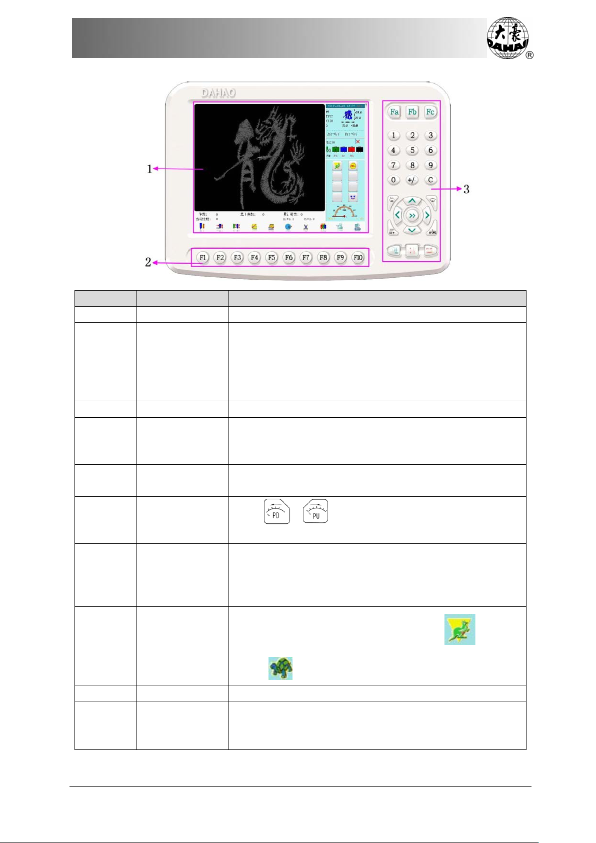
No.
Name
Description
1
LCD
This area displays the operation interface.
Press the function keys within this area to select functions.
(Note: If you press the key twice without interruption by
any other operation, the system will enter or exit the
page key.)
3 +/- Shift
Select negative or positive number.
Include such operations like pattern origin, needle stop at
down position, start elsewhere, sequin, quilting, special
embroidery
If user opens several interfaces, use this key to shift among
these interfaces in order.
to reduce or increase the current
embroidering speed respectively.
Operate by pressing direction keys. Combination of
included angle between two directions).
3
Confirm
Press this key to confirm certain operation.
nder ready status, user can make various preparations,
such as selecting pattern for embroidery, setting pattern
parameters, etc. before confirmation. Then press this key to
2
3
Function
Selection
Assistant
Operations
corresponding function in the main screen area, except the
3 Task Shift
3
3
3
3
Speed
Adjustment
Manual Frame
Movement
Manual
Frame-moving
Speed Shift
Confirm/Release
Embroidery
Press /
direction keys is permitted during manual movement (press
the nearby keys to move the frame along 45 degree of the
Press this key to shift between high speed ( ) and low
speed ( ).
U
BECS-D19 User’s Manual
7
Page 18

Chapter 2 Operation Guide
No.
Name
Description
key to releast the confirmation status and the system
3
Exit
Press this key to exit the current operation.
3
Page
Press this key to turn pages.
3
Number Keys
Used to select menu item or set parameters.
change from ready status ( ) into confirmation status
(
).
Or, under confirmation status, user can pull the bar at any
time to start embroidery. When machine stops, press this
changes from confirmation status ( ) into ready status
( ).
2.3 Instructions of Main Screen
Note: press to shift between the following two pages.
8
BECS-D19 User’s Manual
Page 19

Chapter 2 Operation Guide
No.
Display
Name
Description
Reference
1 Real Time
Tracking
Stitch forms or patterns are displayed in
this area.
2 Current Stitch
Information
The current stitch information is
displayed.
4 Pattern
Information
Information related to the embroidered
pattern is displayed.
5 Color-changing
Position
to make
shift)
Embroidery status (thread
6
Order and
Current Needle
Machine Status
Information (in
the order of left
to right, top to
bottom)
Frame-moving speed (low speed ,
high speed ; press
Main shaft status (running , stop in
position , not stop in position )
BECS-D19 User’s Manual
9
breakage , end of embroidery ,
color-changing , jump , pull bar
to stop )
Page 20

Chapter 2 Operation Guide
No.
Display
Name
Description
Reference
, none cyclic
embroidery (blank)
Assistant embroidery status/flat
al embroidery (flat
7
The set rotation speed and the actual
displayed.
3
If the main shaft fails to stop in position
, press this key
and the main shaft will arrive in
3
When the machine stops, press the key
moving” to move the
frame (e.g. in case of patching). Then
press this key and the frame will
the current design.
3
When the machine stops, press it to have
return to the
start point of the current design.
3 Machine
management
Press this key to enter into the interface
for machine parameter setting and
operations.
Chapter 5
3
Press this key to enter disk management
erface, for operations of floppy disk
and USB.
Chapter 3
3
Press this key to enter into pattern
management interface, to select pattern
for embroidery, input pattern to memory,
Main Shaft
Rotation Speed
Cyclic embroidery
embroidery/speci
embroidery , sequin , etc.)
Start elsewhere
Assistant embroidery mode
Network status (disconnected ,
connected , successful register )
rotation speed of the main shaft is
Main shaft
manual
adjustment
Go to stop
Go to start
parameter
management
point
point
Disk
after machine stops
position .
“Manual Frame-
automatically return to the stop point of
the frame automatically
int
Chapter 6
Pattern
management
10
Chapter 4
BECS-D19 User’s Manual
Page 21

Chapter 2 Operation Guide
No.
Display
Name
Description
Reference
display pattern, generate pattern, operate
letter pattern, etc.
3 Assistant
operations
Operations like pattern origin, needle
stop at down position, start elsewhere,
sequin, quilting, special embroidery, etc.
3
changing order menu, press
relative number to act color-changing.
3
After machine stops, user can press this
key to select trimming upper thread or
trimming bobbin thread.
In this status, press related needle
changing code, system stops the
hen you should act
hanging. Input the
position you need, pull bar to start
embroidering (manual start).
If you set machine to auto
changing, you should first set
current needle locates, system will act
changing according to this order.
changing code,
machine will stop automatically and
change to the needle position that
f you set auto
you set to manual start, pull bar to start.
auto start
3
embroidery
changing order
trimming
color-changing
manual start
Set color
Thread
Manual
When main shaft stops in position ,
press this key; after that, system goes to
the color-
position key to select a position. Pull bar
to start embroidering. When meeting the
colormachine automatically and
displays . T
manual color-c
Chapter 7
Auto
color-changing
manual start
Auto
color-changing
BECS-D19 User’s Manual
11
colorneedle color-changing order (press
in the main screen).
During embroidery, no matter where the
colorWhen you meet color-
already has been set. I
start, machine will start automatically; if
Page 22

Chapter 2 Operation Guide
No.
Display
Name
Description
Reference
3
System is now in normal embroidery
hen you pull bar to start
embroidery, the main shaft rotates and
ame moves along the pattern trace.
ull bar to go back, and machine will
hen machine
System is now in high speed idling
hen you pull bar to start
mbroidery, main shaft will not rotate
and the frame will move along the
hen you pull bar to go
back, main shaft will not rotate and the
frame will move back along the pattern
hen machine stops, press this
System is now in high speed idling
pull bar to stop, the frame goes to the
titch number decreases as well.
3
In embroidery preparation status, you
can make various preparations, such as
to select pattern, set parameter, etc.
Press this key and confirm, then
machine status is changed from
to confirmation
status. W
Normal
embroidery
fr
P
idle back at low speed. W
stops, press this key to shift to low speed
idling .
status. W
e
Low-speed
Idling
pattern trace. W
trace. W
key to change to high-speed idling
status .
status. Pull bar but main shaft and frame
don’t move and stitch number increases;
High speed
idling
Embroidery
preparation
status
12
real position of the current stitch. Pull
bar to back, main shaft and frame don’t
move. S
Pull bar to stop, the frame goes back to
the real position of current stitch. When
machine stops, press this key to change
to Embroidery Status 。
preparation status
status .
BECS-D19 User’s Manual
Page 23

Chapter 2 Operation Guide
No.
Display
Name
Description
Reference
In embroidery confirmation status, you
3
Press this key to enter interface for
manually changing machine head and
color-changing.
3 Special
mode
Press this key to enter interface for
3
Press this key to enter other auxilliary
nterfaces, like clock
setting and help.
3
Press this key to enter operation interface
3
Press this key to enter pattern border
3
Press this key to shift the pattern
Embroidery
confirmation
status
(embroidery
can be
cancelled)
Change
machine head
embroidery
Other assistant
management
Positioning
idling
can pull bar to embroider. When
machine stops, press this key to confirm
to cancel confirmation status and
return to preparation status .
manually shifting special embroidery.
management i
of positioning idling. Chapter 7
Chapter 6
Pattern border
operation
Change design
direction
operation interface. Chapter 7
direction.
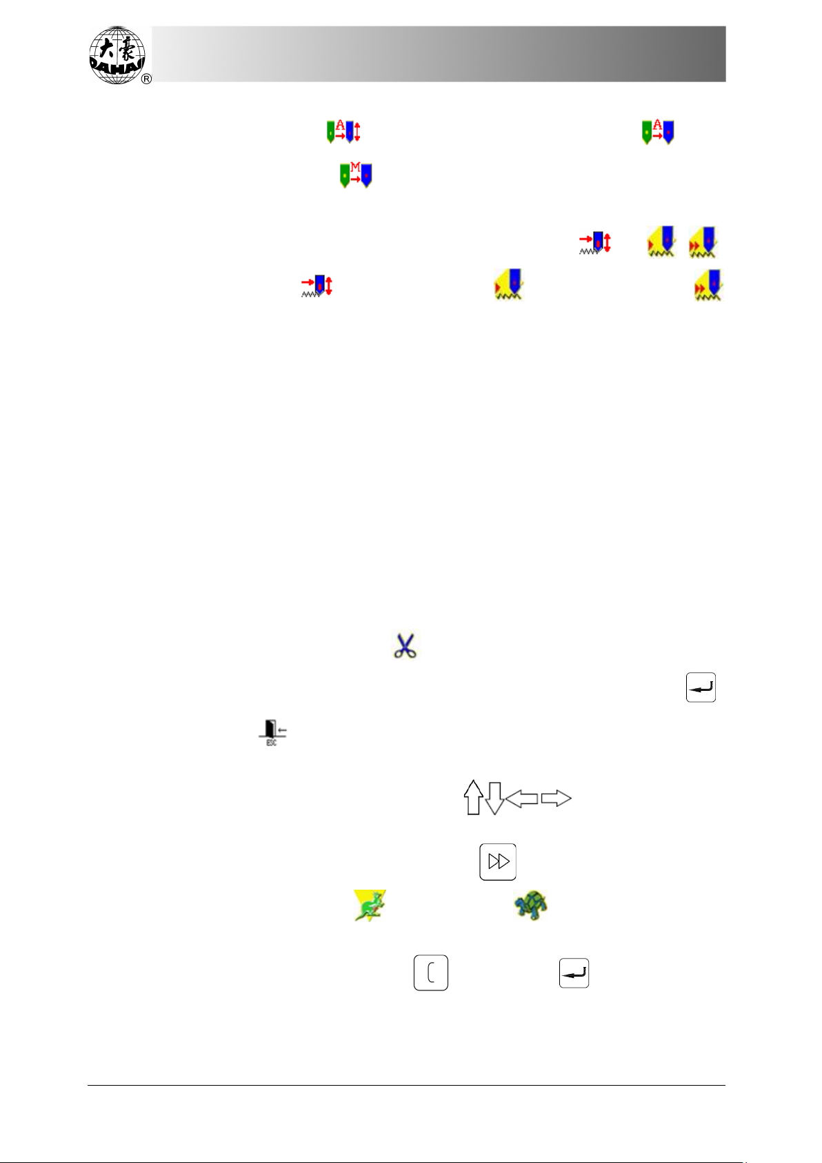
2.4 Notes on Menu Item Status
If one menu item is labeled with the mark “ ” or “ ”, this menu item can not be
accessed and modified. On the contrary, if one menu item is labeled with the mark “ ” or “ ”,
this menu item can be accessed and modified. If there is a “ ”, then this menu item can be
modified only if the user relieves the password first.
2.5 How to Input Number, Letter and Symbol
For some menu items, press the key “ ” to enter setting interface (optional), press
“ ” to shift options, press “ ” to confirm.
At inputting number, press “ ” to input radix point, press “ ” to enter negative
number. If there are several digits or letters on one key, you can press the key continuously
BECS-D19 User’s Manual
13
Page 24

Chapter 2 Operation Guide
Input Pattern
Select Pattern
Auxilliary Operation
Confirm Embroidery
Pull Bar to Embroider
Cancel Embroidery
Manual Operation
until you get the number or letter you want. For example, press trice, then you can get
letter “I”. “ ” is used for shifting capital letters and small letters. “ ” is used for
deleting the last letter you typed in.
2.6 How to Move Cursor
The cursor of this controller is displayed as “ ”. You can press “ ” or
corresponding number keys to move the cursor to the intended item. Press “ ” or “ ” for a
while, the cursor will move consecutively among each item of the present operation interface.
2.7 Basic Embroidery Procedure
The machine embroiders based on the patterns in its memory. The following is the basic
procedure of embroidery.
①
②
③
④
⑤
A. Input Pattern
User can imput pattern through network, floppy disk or USB disk. Only under status,
can user transmit patterns by PC via network. For USB disk operation (including floppy disk),
press in the main screen to enter the “USB disk management” interface. You can also
14
⑦
⑥
BECS-D19 User’s Manual
Page 25

Chapter 2 Operation Guide
input patterns by pressing “ ” under the pattern management interface.
B. Select Pattern
If the pattern management interface is not opened, press in the main interface to
enter it. If the interface is opened but the current interface is about another function, press the
blue task shift key on the panel to enter the pattern management interface. Only under the
status of “ ”, can user choose pattern for embroidery.
1. After entering pattern management interface, press “ ” to select the
intended pattern for embroidery and then press (or ).
BECS-D19 User’s Manual
15
Page 26

Chapter 2 Operation Guide
2. If the pattern’s starting point has been saved, the hint “Move frame to start point”
will display after entering the main screen. Press “ ” and the frame will automatically
return to the start point.
C. Assistant Operation
After selecting the pattern for embroidery, the system will enter the main interface, where
user can make the assistant operation as needed before embroidery.
1. Set repetition, rotation, scaling and color-changing – press in oder to
enter the operation interface of pattern parameter and color-changing order.
2. Set applique embroidery - to enter pattern management interface, where user
can press to set applique following the hints.
3. Check the border, move freely along the border, embroider aong the boarder,
embroider a cross, embroider a line, embroider the pattern outline – press to enter
pattern border interface.
4. Automatically search pattern origin – press to enter assistant embroidery
interface. Please note: this function is to locate the pattern in the center of the frame as
preset by soft limit. To set soft limit area, press to enter other assistant
management operation.
5. Save pattern origin – in embroidery confirmation status, press to enter
16
BECS-D19 User’s Manual
Page 27

Chapter 2 Operation Guide
assistant embroidery interface. Please note: before using this function, user need preset
the origin of the frame. To set the frame origin, press to enter other assistant
management operation.
6. Set cyclic embroidery – press to enter system parameter management interface.
Move the cursor to “Assistant Embroidery Parameter” and select parameter B02 for
parameter setting of cyclic embroidery.
D. Embroidery Confirmation
1. Press after finishing assistant operation. Then press “ ” at the appearance of
the following hint window. Then (embroidery release) will change into
(embroidery confirmation), which indicates that the system has enter embroidery
confirmation status.
If user press “ ”, the system will remain in the embroidery release status. At
this time, even though user pulls the bar, the machine will not work and the system will
display the hint for user to confirm the embroidery.
2. Start elsewhere
After confirmation of embroidery, if needed, press to set another start point
following the hint. (Note: when embroidery starts, this setting is invalid.)
3. Set color-changing and starting method
Under the main interface, press the position where the icon (or , )
BECS-D19 User’s Manual
17
Page 28
Chapter 2 Operation Guide
locates to shift among (auto color-changing, auto start), (auto
color-changing, manual start), (manual color-changing, manual start).
4. Set normal embroidery or idling
Under the main interface, press the position where the icon (or , )
locates to shift among (normal embroidery), (low-speed idling) and
(high-speed idling).
E. Pull the Bar to Embroider
Operation bar (embroidery bar) is under the table.
1. Stop Status:
Pull the bar to right to start embroidery (including low-speed idling and
high-speed idling)
Pull the bar to left to return (including low-speed idling and high-speed idling)
2. Running Status
At normal embroidery, pulling the bar to the right end is to embroider slowly and
releasing the bar will resume the normal speed.
Pulling the bar to left is to stop embroidery (including low-speed idling and
high-speed idling).
F. Manual Operation
1. Manual trimming
When the machine stops, press in the main screen. Follow the prompt and
select a trimming mode (“trim upper & bobbin” or “trim bobbin”). Then press “ ”
to trim, or press “ ”to exit trimming operation.
2. Manual frame-moving
When the machine stops, press the keys (“ ”) to move the frame
in the corresponding direction. Press the neighboring two keys at the same time to move
the frame in the direction of the angle bisector. “ ” is the speed key for manual
frame-moving, to shift between (high speed) and (low speed).
3. Clear the frame coordinates
When the machine stops, press “ ” then press “ ” to clear the XY
displacements displayed in the main screen. The function can be used with manual
frame-moving.
18
BECS-D19 User’s Manual
Page 29
Chapter 2 Operation Guide
4. Manual color-changing
When the machine stops, you may type in needle position number in the main
screen. Then the head will move to the corresponding needle position automatically.
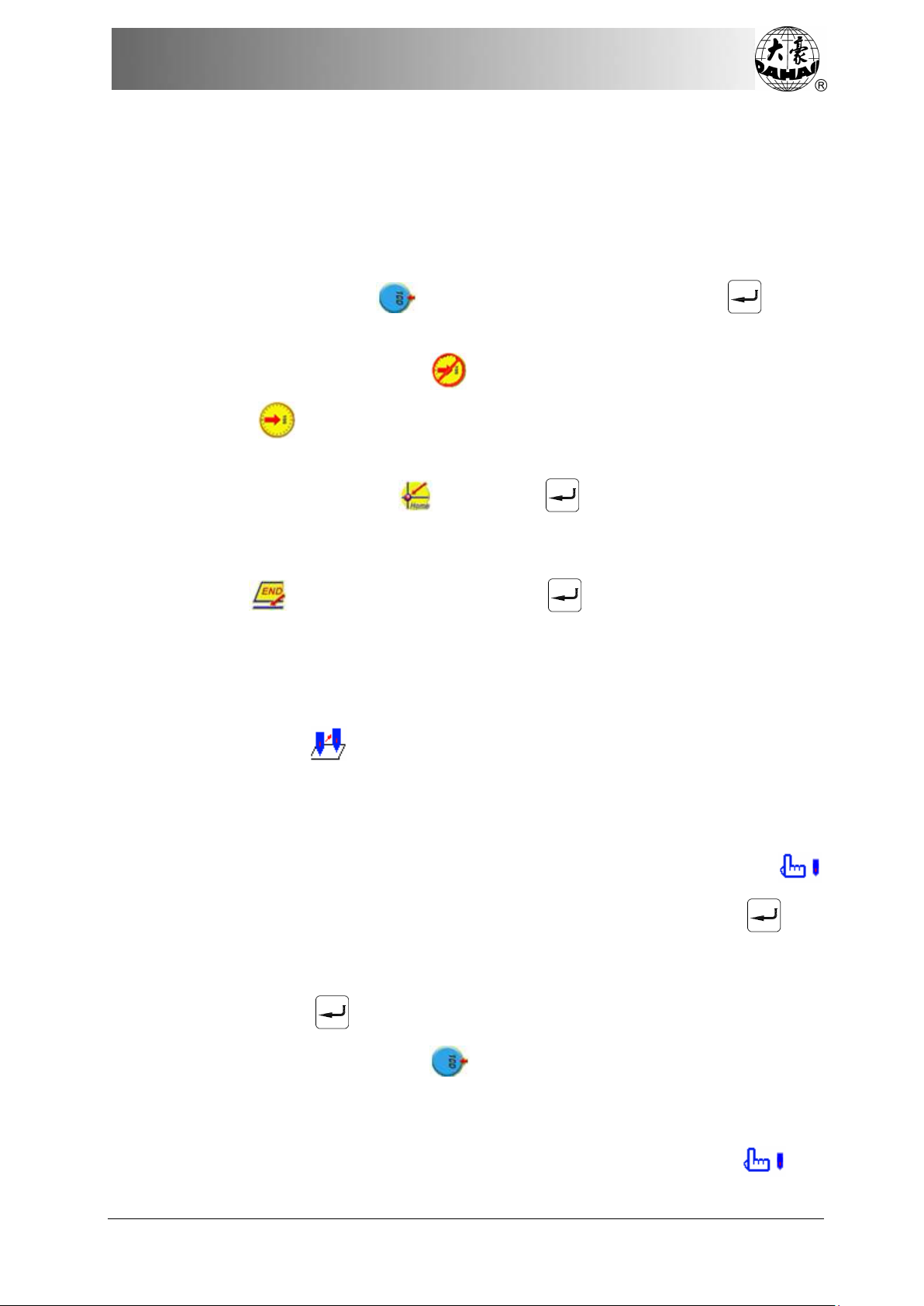
5. Turn the Main Shaft to 100°Manually
Usually the main shaft is needed to stop at 100° at color-changing, frame-moving
and beginning embroidery. The user can manually turn the main shaft to 100° when it
doesn’t reach there. Press “ ” in the main screen and then choose “ ” in the
followed prompt to carry out the function.
After the operation, the icon (main shaft not in the right position) will be
replaced by (main shaft in the right position).
6. Return to start point
In the main screen press and choose “ ” in the followed prompt. Then
the frame will return to the start point.
7. Return to stop point
Press in the main screen and choose “ ” in the followed prompt. Then
the frame will return to the stop point.
8. Positioning idling
Use this function after embroidery confirmation. Positioning idling enables the
machine to move to the designated position according to the user’s need without
embroidery. Press in the main screen then the user can set the needle number,
color-changing code, idling direction and stop code for forward or backward positioning
idling.
9. Needle stops at down position
This function is intended to quilt embroidering at replacing the fabric. Press
in the main screen and then the option “neddle stops down”. When pressing “ ”, the
needle will prick into the embroidery cloth and a prompt will appear. After releasing the
cloth (cloth has to be separated from the frame), move the frame to the designated
position and press “ ”. After this operation, the needle is still down. When the cloth
is placed on the frame again, press to turn the main shaft to 100º manually.
10. Manual operation of pneumatic frame, sequin and special embroidery
This function is functional for the machines that are equipped with pneumatic
frame, sequin and special embroidery devices. For such machines, press and
BECS-D19 User’s Manual
19
Page 30

Chapter 2 Operation Guide
then select the corresponding function item to enter the operation menu.
G. Embroidery Release
When the machine stops, press to display the hint window. Choose “ ” to change
(embroidery confirmation) into (embroidery release).
2.8 Normal Embroidery, Returning and Patch Embroidery
In embroidery confirmation status (the icon appears), push the switch of machine
head (which need perform normal embroidery) to the nor mal embroidery mode, and push the
switch of machine head that needn’t embroider to the down position, and then pull the
operation bar to right and release it to let the machine start normal embroidery. (When you pull
the bar to the right end and don’t release it, the machine will embroider at low speed.) During
the embroidery, pull the bar to left, the machine will stop.
After the machine stops, pull the operation bar to left and the frame will return to its last
position along original path. Pull the bar one time, the frame returns one stitch. Pull the bar
continuously and the frame will return one stitch after another continuously. After t he frame
returns 10 stitches continuously, the frame can return continuously even when you release the
bar. (This may be different for different machine types). When the frame returns continuously,
pull the bar to left again, the frame will stop returning.
The aim for returning is usually to perform patch embroidery. After the returning stops,
push the switch on machine head that need perform patch embroidery to go to the patch mode,
and then pull the operation bar to right and the machine head will start patch embroidery while
other heads remain inactive. When the frame goes to the point from which the frame returns,
other heads whose switches are in normal embroidering mode will start to embroider.
2.9 Relationship between Normal Embroidery, Idling and Positioning Idling
Functions like idling, returning, etc. are intended for the convenience of patching.
Low-speed idling, high-speed idling or positioning idling can be used as needed in embroidery.
In the status of idling, the returning function also has low-speed idling returning, high-speed
idling returning or positioning idling returning.
In the main screen, you may press “ ” (or “ ”, “ ”) to shift among “ ”
(normal embroidery), “ ” (low-speed idling) and “ ” (high-speed idling).
After user sets low-speed idling , the main shaft remains inactive when user pulls the
bar for normal embroidery, but the frame runs forward along the stitch trace. When user pulls
20
BECS-D19 User’s Manual
Page 31

Chapter 2 Operation Guide
bar for returning, the main shaft keeps inactive, but the frame returns along the stitch trace.
After user sets high-speed idling , the main shaft and frame remain inactive, the stitch
number increases. After user pulls the bar for halting, the frame moves directly to the actual
position of the current stitch number. When user pulls bar for returning, the main shaft and
frame keep inactive, but the stitch number decreases. After user pulls the bar for halting, the
frame returns directly to the actual position of the current stitch number.
The positioning idling can move the frame directly forward (or backward) to a designated
position, or to the latest color-change position, or even to the latest stop-code position. In the
main screen press and the user can select forward/backward positioning idling by
stitche number, color change code or stop code. After the system returns to the main screen,
user can pull the bar forward /backward to complete the positioning idling.
2.10 Embroidery Operation Bar and Turn Shaft Button
A. Embroidery operation bar (embroidery bar or operation bar, under the table)
Stop Status:
Pull the bar to right to start embroidery (including low-speed idling and
high-speed idling)
Pull the bar to left to return (including low-speed idling and high-speed idling)
Running Status:
Pulling the bar to the right end is to embroider slowly and r eleasing the bar will
resume the normal speed.
Pulling the bar to left is to stop embroidery.
B. Turn shaft button (on the operation bar case, at right side under the table)
Press the button to make the main shaft rotate one circle and stop at 100±2.5°.
2.11 Thread Breakage Detection and Patch Embroidery Sw itch
Based on different working principles, thread-breakage detection devices are divided into
three types: thread take-up spring type, thread winding wheel (chopper wheel) type and mixed
type.
For thread take-up spring type, it warns thread-breakage by detecting connection of
take-up spring and contact point. When thread breaks, the spring will close to the contact point.
In normal condition, this detection device reacts sensitively to upper thread breakage, but can
hardly detect bobbin thread run-out. In case you change the embroidery thread, or thread
tension changes, you need to adjust spring pressure between the take-up spring and contact
point. When the spring pressure is too large, there will be False Positive; when the spring
pressure is too small, there will be False Negative.
For thread winding wheel type, it judges thread-breakage by checking the winding wheel
angle. It reacts very sensitively in case of upper thread breakage; in most cases of bobbin
thread run-out, the consumption of upper thread will reduce, as a result, system will judge by
BECS-D19 User’s Manual
21
Page 32

Chapter 2 Operation Guide
statistic method and send out warning. Though it can almost avoid False Negative, it is not as
sensitive as the spring-type.
For the mixed type method, these two detection methods can complement each other with
their advantages, which results in sensitive and stabilized detecting effect.
No matter which method you use, there is one switch and one status light on each machine
head. There are three positions to switch but only two positions can be locked. When you
switch to the down position, status light does not shine, which means the head stops
embroidering. When you switch to the middle, status light is green, which means the head is
now in normal embroidery. In case of thread-breakage, machine stops and status light on that
particular head turns red. System automatically changes to patching mode on that head. If you
want to set a single head to patching mode manually, you can switch to the upper position,
which can not be locked. When you release the switch, it returns to the middle. Meanwhile,
status light on this head will turn red to indicate that patching mode is available on this head.
2.12 Working Status
The machine has three working statuses:
1. Preparation status
other preparation works;
2. Embroidery confirmation status - confirm the parameter settings to enter the
quasi-running status;
3. Embroidery running status - embroider the pattern.
How to shift among the above working statuses?
In preparation status ( is displayed), after selecting embroidery pattern from the
memory and setting the parameters, user needs press “ ” and “ ” to enter embroidery
confirmation status (
embroider, which means the machine is in embroidery running status ( is displayed).
In embroidery running status ( is displayed), pull the bar to left t o stop, and now the
- preset parameters; choose embroidery patterns and perform
is displayed). User should pull the embroidery bar to right to
machine is in embroidery confirmation status (pull the bar to right again and the machine goes
into embroidery running status).
In embroidery confirmation status ( is displayed), first press “ ” and then press
“ ” to release embroidery confirmation status. Now the machine enters preparation status
(
22
is displayed).
BECS-D19 User’s Manual
Page 33

Chapter 3 Disk Management
Chapter 3 Disk Management
In disk management interface, users can input the pattern data from disk to machine, and
vise versa; meanwhile, users can conduct some common disk managing actions, like erasing
file or catalogue, formatting disk, etc. Floppy disk (external device) and USB disk are both
supported. Users can save pattern data based on different types. The system recognizes formats
like DOS, FDR and ZSK. However, FDR and ZSK files are read only and cannot be deleted,
formatted and outputted. Pattern formats like DSB, DST and DSZ can be read. For data output,
pattern data will be saved as DSB format.
3.1 Disk Selection
Since the system supports more than one storage device, please choose the target disk.
A. Press in the main screen
B. System will display current disks. Press the icon of the intended disk and press
“ ” or to quit.
In this selelction window, all the storage devices will be displayed. Their information
includes the icons, words and numbers. The icon is the device type. means USB dis k and
means floppy disk. Words mean volume lable (if there is no volume lable, default words
will be used) and the numbers within the brackets mean the digital ID of the disk.
C. Enter Disk Management Interface
BECS-D19 User’s Manual
23
Page 34

Chapter 3 Disk Management
No.
Icon
Name
Description
1
File List
Display the pattern files and folders of the disk in
icons. It’s used to select files
2
Pattern Preview
Display the shape of selected pattern and its
information.
3
Single/Multiple
multiple-selection.
4
Select All
(only available under multiple-selection mode).
5
Pattern Input
Copy pattern from disk to memory
6
Pattern Output
Copy pattern from memory to disk
7
Previous
Directory
Return to the previous directory
8
Refresh Disk
Refresh current disk directory
9
Create New
Directory
Create new directory within the disk
10
File Deletion
Delete the seleted file
Press to turn page; press to turn the page of patterns.
Seletion
Shift between single-selection and
Select all items with the current directory
24
BECS-D19 User’s Manual
Page 35

Chapter 3 Disk Management
No.
Icon
Name
Description
11
Disk Formatting
Format current disk
12
Letter
Embroidery
Conduct letter embroidery
13
Help
Display the online help at the disk management
interface.
14
Current Browse
Path 15
Page Information
Display the current page and total page number
16
Memory
Capacity
Display the memory capacity and the remaining
space
17
Pattern Date
Only pattern file can be displayed
18
Pattern Stitch
Number
Display the stitich number (only available for
pattern file)
19
Object Name
Pattern file name or directory name
20
Object Icon
Icon represents the file type:
: directory
: DSB pattern
: DST pattern
3.2 Pattern Preview
1. In the disk management interface, press “ ” to select the pattern for
preview.
BECS-D19 User’s Manual
25
Page 36

Chapter 3 Disk Management
Pattern files and folders are shown by icon in the list. Each page contains 20 objects. If the
objects are more than 20 in current directory, please turn to another page to look for other
patterns. You can also use to find pattern in other pages. The selected object has
a blue frame.
2. Press to display as follows:
The system loads the data from the disk and displays the pattern’s image according to a
26
BECS-D19 User’s Manual
Page 37

Chapter 3 Disk Management
certain ratio. At the same time the pattern’s peripheral information and color-changing number
will be displayed.
Note: User can select more than one pattern for preview. For selecting more than one
pattern, please refer to chapter 3.3.
3.3 Single/Multiple Selection
Before preview, input and deletion of patterns, the target pattern has to be selected first.
The user can select one object or several objects at one time to improve efficiency.
1. Press “ ” to select objects
By default setting, the first object in the page is selected while others are not selected.
Press “ ” to select, and then the icon and word information of the selected
pattern will be showed within the blue square.
2. Single/multiple selection switch
When user selects the objects, the system is in single or multi-selection mode. In
single-selection mode, only one object can be selected and selecting another object will
automatically cancel the last selection. Press the switch key to shift between the two modes. In
multi-selection mode, user can select several objects. In the single selection mode the switch
key displays as , while in the multi-selection mode it displays as .
3. Select several objects for operation in order
In multiple-selection mode, user can press “ ” to select the object and then
press “ ” to confirm the selection, and repeat the same operation to make multiple
selections. If user need cancel any selection, move to the selected object and press “ ”
again to cancel.
BECS-D19 User’s Manual
27
Page 38

Chapter 3 Disk Management
4. Press to select all
The key is effective only in the multi-selection mode, where pressing this key will have all
the objects within the directory selected.
3.4 Pattern Input
To input pattern data from disk to the machine’s memory, the user has to select files from
one or more disks first, and then input the pattern number and name for the file to be saved.
1. Select one or more files in the disk;
2. Press and the system will require user to input the pattern number and name in
the memory;
3. Input the pattern number and name in the memory.
The system provides the minimum available pattern number as the default value, when
user enters the interface for inputting the pattern number and name in the memory. User can
28
BECS-D19 User’s Manual
Page 39

Chapter 3 Disk Management
use the keyboard to change the value. When several patterns are inputted at one time, the user
can only input the number of the first pattern.
At modifying the pattern number and name, the system will first change the pattern
number. After the modification, press “ ” and the system will automatically enter the item
for changing pattern name. Please input the name following the hints.
4. Press “ ” and the system will save the pattern data in memory.
3.5 Pattern Output
User can output pattern data from memory to the current disk.
1. Press
2. Select the pattern for output
The system displays the list of patterns saved in memory. User can select patterns for
output, and then press “ ”.
3. Input pattern number and name in the disk
BECS-D19 User’s Manual
29
Page 40

Chapter 3 Disk Management
System uses the pattern name in memory as the default name in disk. User can use the
keyboard to change the corresponding value.
The method of modification is the same as that in “Pattern Input”. User need press “ ”
to save the modification.
4. System will return to disk management interface and refresh the file list of the current
directory. At any previous step, user can press “ ” to quit.
3.6 Directory Operation
1. Enter the directory
Select the directory and press “ ”. System reads the item list of the directory and
refreshes the interface.
2. Return to previous directory
Press “ ” and system will return to previous directory and refresh the interface.
3. Create new directory
Press “ ” and system will display a dialogue box for user to input the name for the
new directory. Press “ ” to create the new directory and system will refresh the current
directory list.
3.7 Delete Disk File (Including Pattern File and Directory)
1. Select one or several objects for deletion (See 3.3)
30
BECS-D19 User’s Manual
Page 41

Chapter 3 Disk Management
2. Press
3. System will remind you to confirm the deletion
4. Press “ ” to delete and press “ ” to quit.
Note: If user chooses to select the directory for deletion, system will delete all the files
and sub-directory in this directory. If a file has the property of “only read” or “disk writeprotection”, the file will not be deleted.
3.8 Disk Formatting
1. Select the disk to be formatted (See 3.1)
2. Press “ ”
BECS-D19 User’s Manual
31
Page 42

Chapter 3 Disk Management
System will display the disk formatting box, where will be displayed the storage
information of the current disk, warning information for disk formatting and formatting process
bar as well as Start and Return button.
3. Press “ ”
System will begin to format the disk and show the speed with a process bar. After
formatting, the system will display a hint to show formatting success. Press the Return key to
return to the disk management interface.
Note: system will format the disk in DOS format.
32
BECS-D19 User’s Manual
Page 43

Chapter 4 Memory Pattern Management
Chapter 4 Memory Pattern Management
Memory pattern management includes embroidery pattern selecting, settings and transfer
and creation.
4.1 Memory Pattern Management Interface and Other Instructions
Press in the main interface to enter the memory pattern management interface.
The memory pattern management interface includes: pattern display area, information
area and function menu area. The pattern image display area can show 9 patterns at most;
beyond that, more pages will be needed. The function menu area is used for preview and order
setting.
BECS-D19 User’s Manual
33
Page 44

Chapter 4 Memory Pattern Management
34
BECS-D19 User’s Manual
Page 45

Chapter 4 Memory Pattern Management
No.
Icon
Name
Description
Pattern Amount and
Memory Information
Display the total number of patterns and the
memory information
Pattern Information
Display
Display the related information of selected
pattern
Browse Pattern
Display pattern files in the memory in icon,
mainly for the purpose of selection
Page Information
Display the current page number and total
number of pages
Select Pattern
In embroidery preparation status, press this
modifications
Pattern Preview
This key is used to view the details of the
analog display the pattern
Disk Operation
More disk operation, please see chapter 3
Copy Pattern
Press this key to enter pattern copying
interface
Edit Pattern
See chapter 8, how to edit selected or new
pattern
Press to shift among pages; press to shift page of patterns.
1
2
3
4
5
6
key to enter modification interface of pattern
parameters and the pattern will be used for
embroidery after confirming such
pattern, and to scale up/down, move or
7
8
9
BECS-D19 User’s Manual
35
Page 46

No.
Icon
Name
Description
10
Delete Pattern
Press this key to delete selected pattern
Appliqué Pattern
Setting
Press this key to enter appliqué pattern
setting
Satin Stitch
Compensation
Set the satin stitch compensation of the
memory pattern
Edit Combined Pattern
Press this key to enter edit interface of
combined pattern
Devide Pattern
Separate one pattern into two patterns
Integrate Patterns
Combine two patterns into one pattern
Generate High-speed
Pattern
Press this key to enter interface for
generating high-speed pattern
Generate Standard
Pattern
This function is used to generate standard
Generate Pattern by
Parameters
To generate pattern by embroidery
parameters
Generate Pattern by
Frame-moving
Press this key to enter the interface for
generating pattern by frame-moving
Generate Outline
Pattern
Press this key to enter the interface for
pattern
Copy Pattern with
Varied Stitch Length
Copy pattern according to the set stitch
length
Pattern Parameter
Operation
Press this key to enter pattern parameter
operation
Input Pattern from PC
Press this key to input pattern from PC
Letter Embroidery
Press this key to enter letter embroidery
operation (See chapter 9)
Help
Display the online help for pattern
management interface
Clear All Patterns
Press this key to clear all selected patterns
from memory
11
Chapter 4 Memory Pattern Management
12
13
14
15
16
17
18
19
20
Pattern from Combined
Pattern from Normal
pattern from combined pattern
generating outline pattern from normal
21
22
23
24
25
26
See the following specifications for each operation. Press the key “ ” to return to the
memory pattern management menu.
36
BECS-D19 User’s Manual
Page 47

Chapter 4 Memory Pattern Management
4.2 Select One or Several Patterns
Before any operation on patterns, you must select the target patterns. You can select one
pattern or select several patterns at a time to improve efficiency.
1. Press “ ” to select targets
By default, the first item in the page is the selected one. Press “ ” key or
directly use the pattern number key to select others. The icon and words of the selected target
appears within the blue squares.
During selection, if system is in multi-selection mode, user can select several objects.
2. Select several patterns in order
In multiple-selection mode, user can press “ ” or the pattern number key to
select target item and press “ ” to confirm selection. Repeat the process to select more. Or
you can press “ ” to cancel the selection.
4.3 Select Pattern for Embroidery
1. Select a new pattern for embroidery and make sure system is in preparation status
2. In the main interface, press to enter memory pattern management interface.
3. Select the pattern for operation in the pattern image area of the memory pattern
management interface.
4. Press “ ” to enter modification interface of memory pattern parameter setting.
There are 30 parameters relating to the pattern, some of them can only be modified after
the administrator password is released. The setting method of it is the same as other parameter
setting procedure. Please refer to 5.2 for details.
5. After changing the pattern parameter, press “ ” to confirm the pattern for
embroidery. If the operation is completed, system will close the memory pattern screen to
return to the main screen.
.
4.4 Pattern Preview
The selected pattern can be previewed in the memory pattern preview interface according
to the preset way, to check details of the pattern.
BECS-D19 User’s Manual
37
Page 48
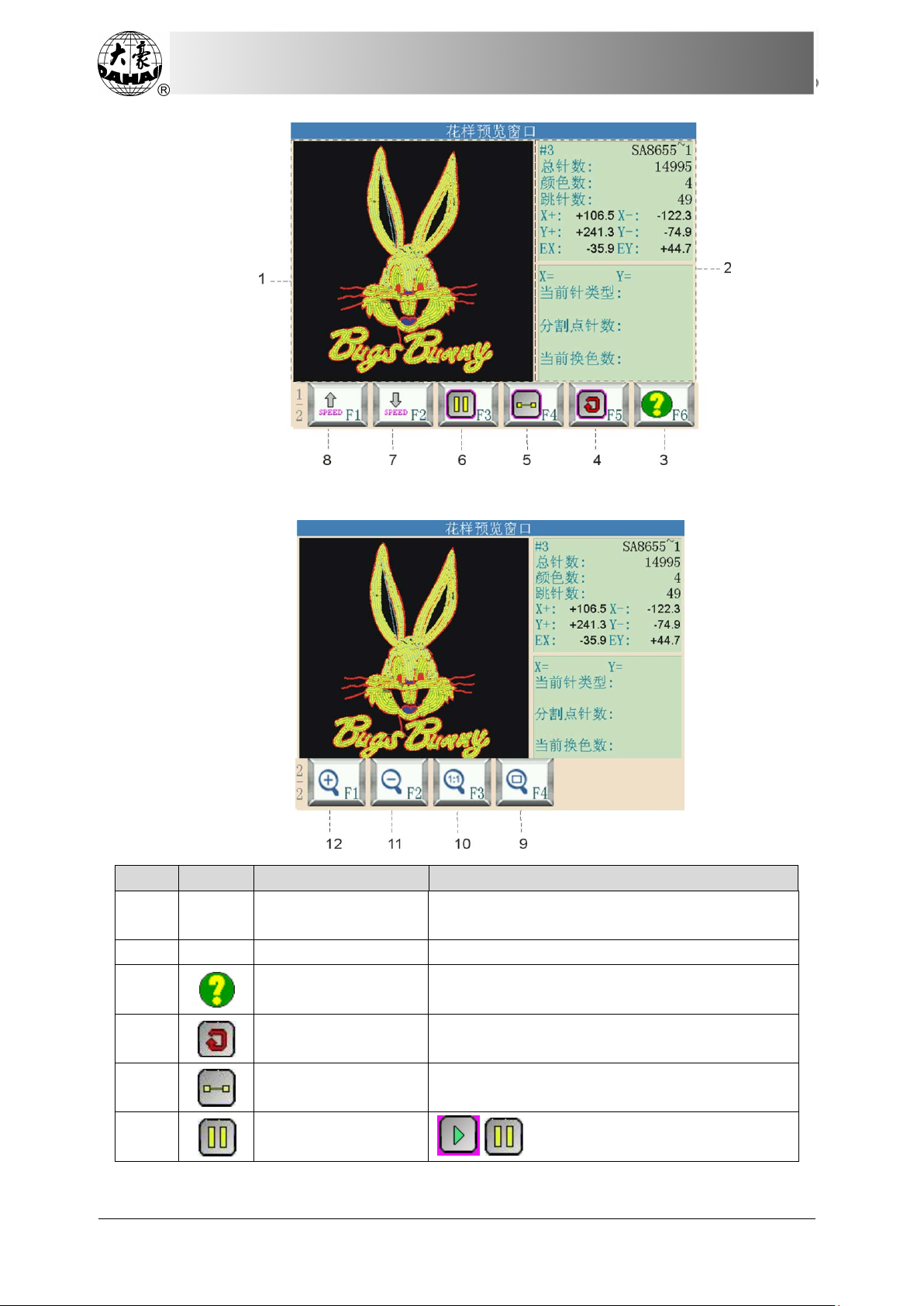
Chapter 4 Memory Pattern Management
No.
Icon
Name
Description
Pattern Preview
Area
Display the selected pattern on the patternated
way and speed.
2
Pattern Information
Display the pattern information.
Help
Display the help menu.
Redraw
Display the selected pattern again.
Single Step Display
Draw the pattern by single steps.
Draw/Pause Switch
/ is for switching between drawing
1
3
4
5
6
38
BECS-D19 User’s Manual
Page 49

No.
Icon
Name
Description
pattern and pausing the drawing.
7
Speed Down
Decelerate the display.
Speed Up
Accelerate the display.
Window Display
Display the pattern to the full size in the
pattern preview area.
Real Size Display
Display the pattern in its actual size in the
pattern preview area.
Scale Down
Scale down the pattern picture in the pattern
preview area.
Scale Up
Scale up the pattern picture in the pattern
preview area.
Chapter 4 Memory Pattern Management
8
9
10
11
12
1. Press in the main interface to enter the memory pattern management interface.
2. Select a pattern in the pattern image area of the memory pattern management screen.
3. Press in the memory pattern interface to open pattern preview interface.
4. Press in the pattern preview area to control the pattern size and press
“ ” to control the pattern display position. Press to locate the pattern to
the center. Press to control the pattern display speed. Press to control
the pattern display and pause. Press to automatically switch to halt for single step
pattern display. And press to resume normal display. Press
selected pattern.
to re-display the
4.5 Copy Memory Pattern
1. Press in the main menu to enter the memory pattern management interface.
2. Select intended pattern in the pattern image area of the memory pattern management
interface.
3. In the memory pattern management interface, press “ ” to enter the operation
interface for copying memory pattern. At this time, system will automatically provide the
available smallest pattern number and default pattern name. If the user doesn’t want to change
them, go to step 6 directly.
BECS-D19 User’s Manual
39
Page 50

Chapter 4 Memory Pattern Management
4. If new pattern number is needed, input the new pattern number, and press “ ” to
confirm the change.
5. System will automatically enter pattern name modification area. If user wants to change
it, input the new pattern name.
6. Press “ ” to confirm the change and conduct the copying operation, or press
“ ” to cancle the copying opera tion, system will return to the pattern operation selection
40
BECS-D19 User’s Manual
Page 51

Chapter 4 Memory Pattern Management
interface.
4.6 Delete Memory Pattern
This operation is to delete one or several pattern from the machine.
1. Press in the main interface to enter memory pattern management interface.
2. Select patterns for deletion. User can select one or several patterns.
3. Press to enter the operation interface for deleting memory pattern.
If you want to clear all the memory patterns, press to enter the operation interface
for clearing all memory patterns.
BECS-D19 User’s Manual
41
Page 52

Chapter 4 Memory Pattern Management
4. Press “ ” to delete pattern or press “ ” to give up pattern deleting operation,
system will return to the pattern operation selection interface.
4.7 Applique Pattern Setting
System has two ways for appliqué embroidery: manual moving frame out and automatic
moving frame out.
Manual moving frame out: when meeting the stop code, the machine will stop
automatically. User needs move the frame to the proper position for appliqué with the manual
frame-moving button. Then you may press and “ ” to return to the stop point. At
last pull the bar for embroidery.
Automatic moving frame out has two ways: by moving frame to the offset point or by
setting the moving distance. The operation is as follows: firstly, set appliqué embroidery
function for the pattern. Then, when reachi ng the appliqué point, the machine moves to the
offset point (which has to be set) or move out according to the set distance. After appliqué,
pull the bar and the machine will automatically return to the stop point to continue
embroidery.
The following is how to set appliqué for the pattern:
1. Press in the main interface, to enter memory pattern management interface.
2. Select the target pattern in the pattern image area of the memory pattern management
interface.
3. Press “ ” to enter the operation interface for setting appliqué for the pattern as
42
BECS-D19 User’s Manual
Page 53
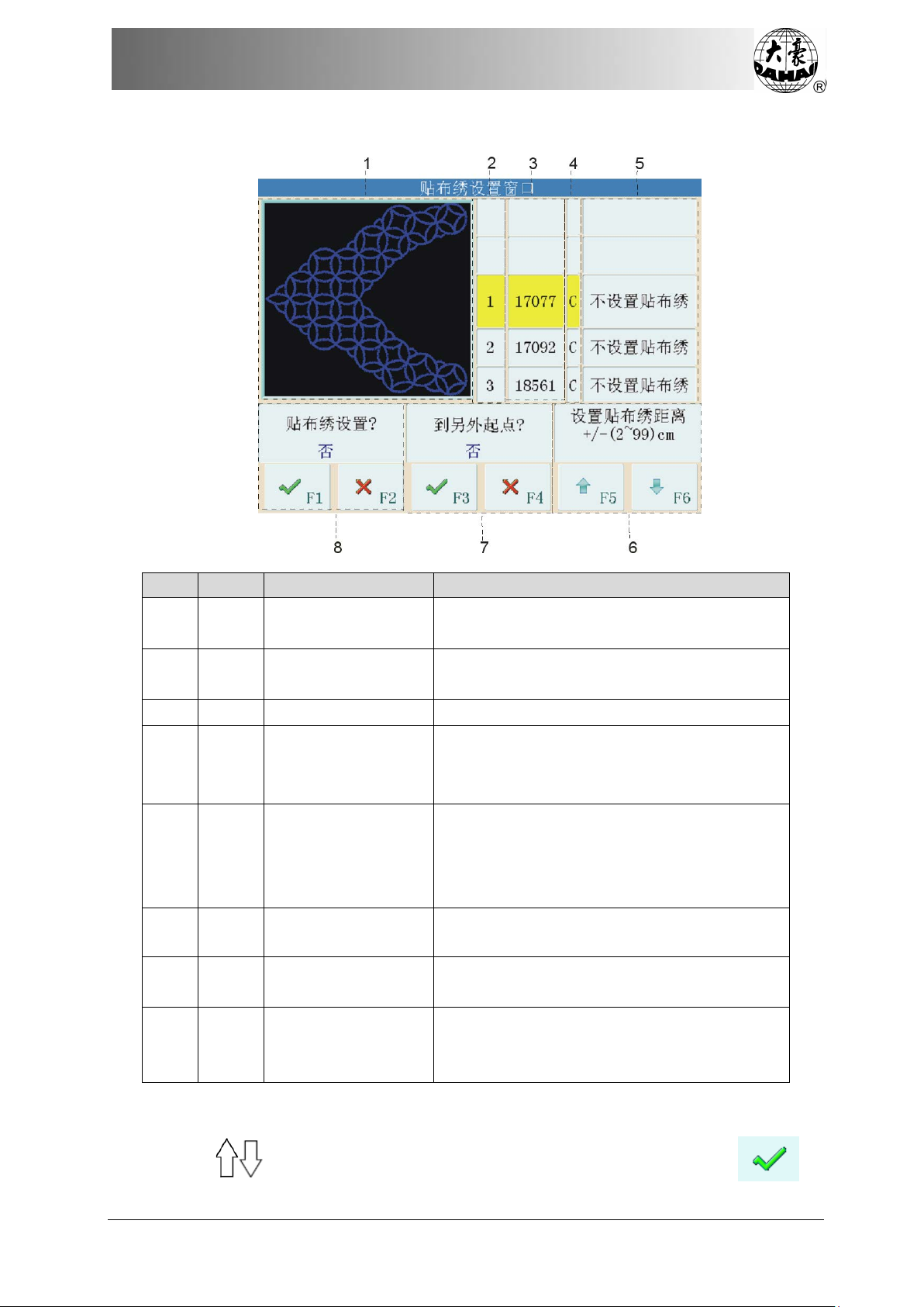
below:
No.
Icon
Name
Description
Pattern display area
machine embroiders to the appliqué point
list
set appliqué point.
3
Stitch number list
Display the stitch number at that position.
S: stop code
3.Appliqué distance
Frame-out distance
Select the appliqué distance (frame-out):
(2cm to 99cm) or (-2cm to -99cm)
offset position
selecting list
Chapter 4 Memory Pattern Management
1
2
4
5
6
7
8
Real-time display of the pattern when
Sequence number
Show the sequence number of the position to
Type list The stitch code type
C: color-changing code
Option list Type of appliqué at this position:
1.No appliqué
2.Set offset position
Whether to go to the
Appliqué
Choose whether to set the offset position
Choose whether to set appliqué embroidery.
embroidery
The pattern display area shows the pattern which is being set with appliqué. After user sets
the appliqué position, the pattern will be refreshed and the result will appear directly.
4. Press to move the list to the position for applique, and then press in
BECS-D19 User’s Manual
43
Page 54
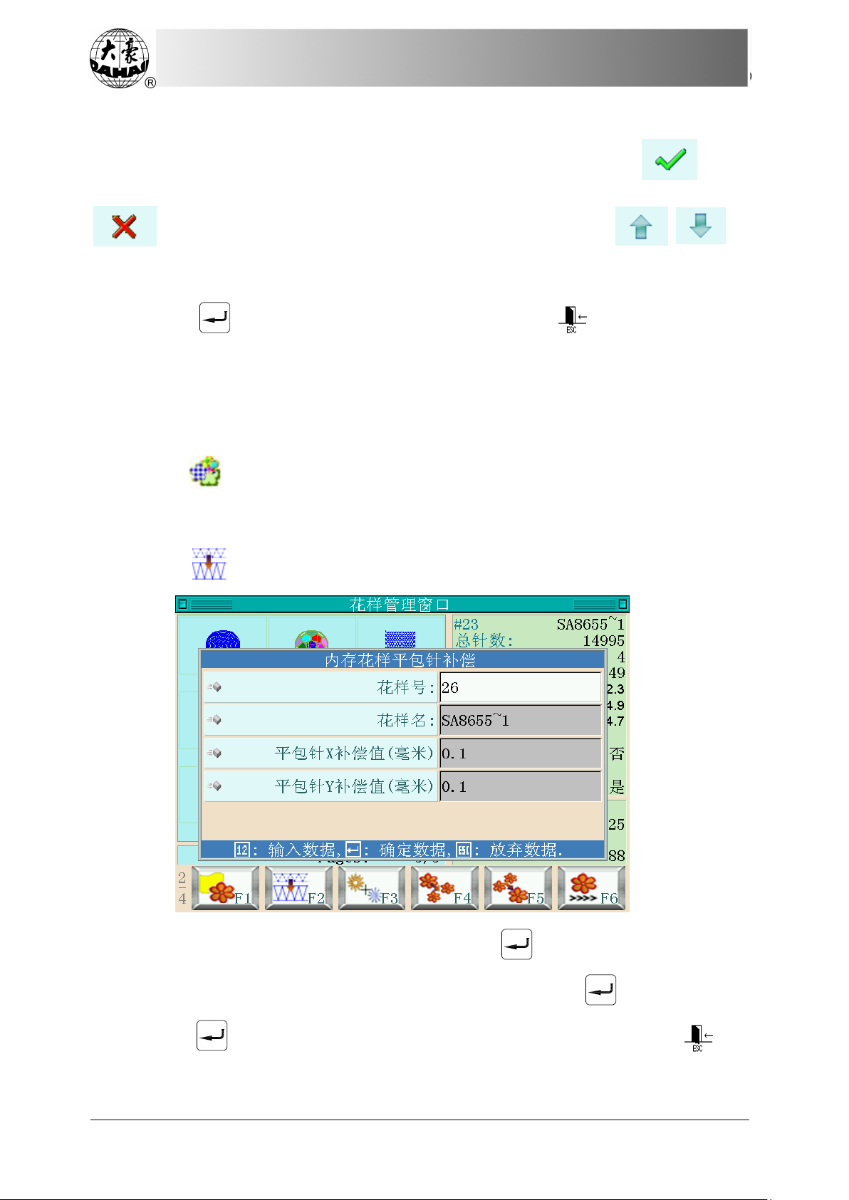
Chapter 4 Memory Pattern Management
the dialog box, hinting “Set applique?”
5. If user chooses to move the frame out to the offset position, press in the
dialog box, hinting “To Offset position?”. If the frame-out is at the fixed distance, firstly press
in the dialog box, hinting “To Offset position?”, and then press to
set the moving-out distance: (2cm to 99cm) or (-2cm to -99cm).
6. Repeat steps 4 & 5, to set all the appliqué positions of the patte rn.
7. Press “ ” to save the appliqué information or press “ ” to cancel operation,
system will return to the pattern operation selection interface.
4.8 Satin Stitch Compensation
This operation is to adjust the satin stitch width in the pattern according to need.
1. Press in the main interface, to enter memory pattern management interface.
2. Select the target pattern in the pattern image area of the memory pattern management
interface.
3. Press “ ” to enter satin stitch width adjustment interface.
4. If user doesn’t want to use the default value, press “ ” to change it with keyboard.
5. Input the value of “satin stitch X (Y) compensation” and press “ ” to confirm.
6. Press “ ” to adjust the satin width and save it as a new pattern or press “ ” to
cancel the adjustment operation, system will return to the pattern operation selection interface.
44
BECS-D19 User’s Manual
Page 55

Chapter 4 Memory Pattern Management
4.9 Edit Combined Pattern
The combined pattern means a combined group of certain memory patterns (less than 99)
after user sets their parameters. The combined pattern is set as automatic continuous
embroidery. In the memory pattern management interface, the icon of the combined pattern is
displayed as . To embroider a combined pattern, user needs return to the memory
pattern management interface after creating or editing the combined pattern. If it’s already in
the embroidery preparation status, user should select the pattern and the system will
automatically return to the main interface. Then after embroidery confirmation, user can pull
the bar for embroidery. User can also compile the combined pattern into normal pattern by
using the edit function, so as to check and embroider the pattern.
1. Press in the main interface, to enter memory pattern management interface.
2. To edit the saved combined pattern, user need select that combined pattern first. To
create a combined pattern, user need carry out the following operations.
3. Press “ ” to enter operation interface for editing combined pattern.
The serial number indicates how many patterns to form the combined pattern and the
number of currently operated pattern.
4. Set the parameters of the first pattern, including pattern number, scaling ratio, rotating
angle, pattern direction and priority mode as well as color-changing order.
5. Press to set many patterns to be combined, and press to return to the
parameter setting of each pattern to be combined.
If the current pattern is not the first pattern in the combined pattern, user should set the
interval between it and the first pattern.
BECS-D19 User’s Manual
45
Page 56

Chapter 4 Memory Pattern Management
6. Press “ ” to save the combined pattern.
7. Input the pattern number and name and press “ ” to save the pattern or press
“ ” to quit saving the combined pattern, system will return to the pattern operation
selection interface.
46
BECS-D19 User’s Manual
Page 57

Chapter 4 Memory Pattern Management
4.10 Devide Pattern
This operation is to devide one pattern into two patterns at a pointed stitch.
1. Press in the main interface, to enter memory pattern management interface.
2. Select the target pattern in the pattern image area of the memory pattern management
interface.
3. Press to enter the interface for deviding pattern.
4. If you do not use the default value, please input the pattern number, pattern name,
division stitch number by the keyboard, then press “ ” to confirm them.
5. Press “ ” to divide the pattern into two new patterns or press “ ” to cancel the
operation, system will return to the pattern operation selection interface.
4.11 Integrate Patterns
This function is to combine two patterns into a new one. The interval between the two
patterns is the distance from the end point of the first pattern to the start point of the second
pattern.
1. Press in the main interface, to enter memory pattern management interface.
2. Choose two patterns in pattern selecting area, and press “ ” to enter the operation
interface for integrating patterns. If More than two patterns are selected, there will be a prompt
to tell you to reselect.
3. If yo u don’t use the default value, you can use keyboard to change the pattern number,
BECS-D19 User’s Manual
47
Page 58
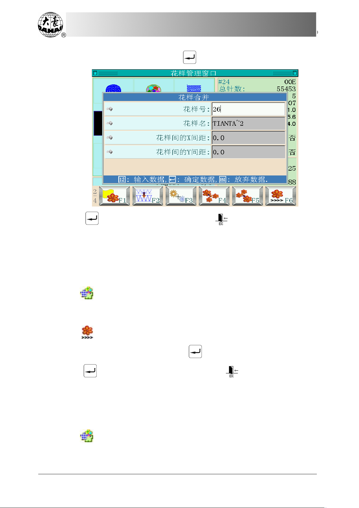
Chapter 4 Memory Pattern Management
pattern name and X (Y) interval, and then press “ ” to confirm.
4. Press “ ” to integrate the patterns or press “ ” to quit the operation, and
system will return to the pattern operation selection interface.
4.12 Generate High-speed Pattern
The function can cut the long stitch form into short ones, which keeps embroidery in
consistent high speed.
1. Press in the main interface, to enter memory pattern management interface.
2. Select the target pattern in the pattern image area of the memory pattern management
interface.
3. Press “ ” to enter the operation interface for generating high-speed pattern.
4. If user doesn’t use the default value, press “ ” and change the value by keyboard.
5. Press “ ” to generate high-speed pattern or press “ ” to cancel the operation,
system will return to the pattern operation selection interface.
4.13 Compile Combined Pattern
This operation is used to generate a normal pattern from a combined pattern.
1. Press in the main interface, to enter memory pattern management interface.
2. Select a saved combined pattern.
48
BECS-D19 User’s Manual
Page 59

Chapter 4 Memory Pattern Management
3. Press “ ” to enter the operation interface for generating a standard pattern from a
combined pattern.
Input the new pattern number and name as required.
4. Press “ ” to save the pattern or press “ ” to quit saving, system will return to
the pattern operation selection interface.
4.14 Generate Pattern by Parameters
This operation is to change the setting of color-changing order and normal parameters
such as scaling and repetition, which is attached to a specific pattern, so as to create a new
pattern.
1. Press in the main interface, to enter memory pattern management interface.
2. Select pattern in the pattern image area of the memory pattern management interface.
3. Press “ ” to enter the operation interface for generating pattern by parameters.
BECS-D19 User’s Manual
49
Page 60
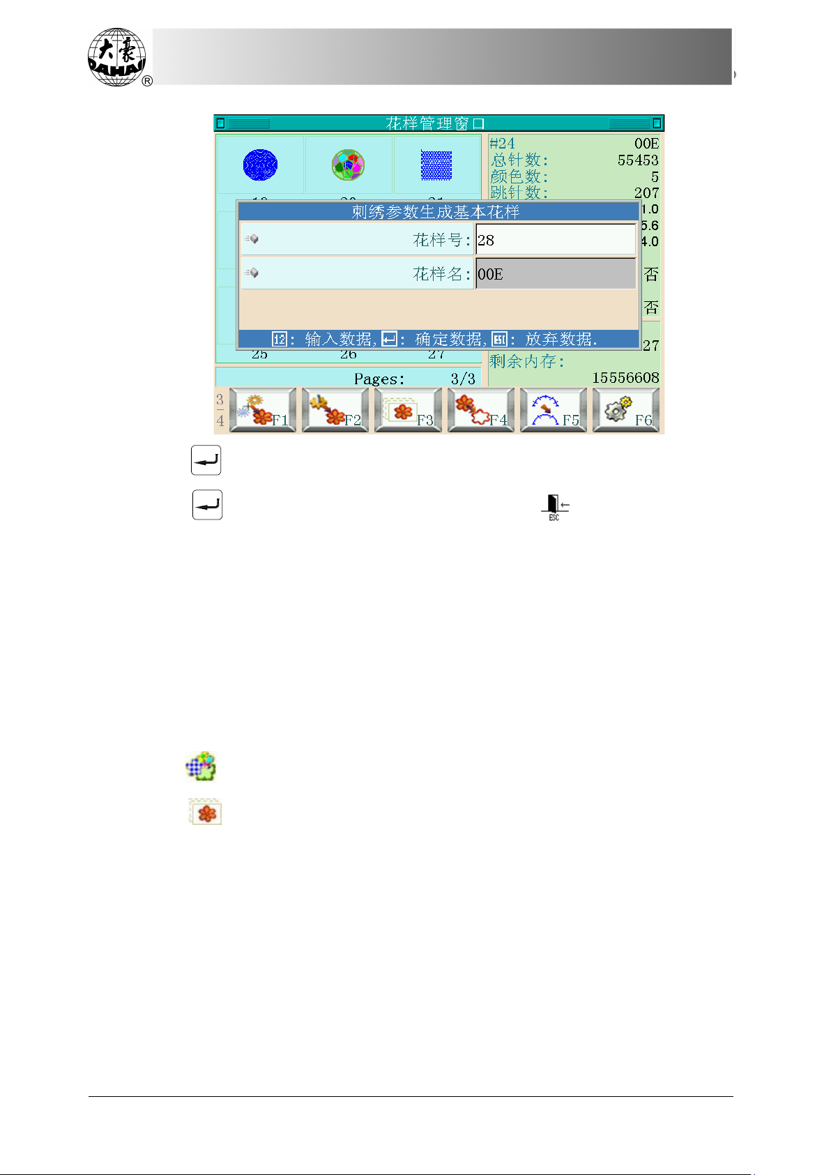
Chapter 4 Memory Pattern Management
4. Press “ ” to input new pattern number and name.
5. Press “ ” to generate pattern by parameters or press “ ” to quit the operation,
system will return to the pattern operation management interface.
4.15 Generate Pattern by Frame-moving
The user often wants to embroider the boundary of a pattern before embroidering it, so as
to provide convenience to the later appliqué operation. This function can create such a pattern,
and you can select the new pattern to embroider the boundary for the purpose of pattern
positioning.
1. In embroidery preparation status, move the frame to the point where the generated
pattern starts.
2. Press in the main interface, to enter memory pattern management interface.
3. Press “ ” to enter the operation interface for generating pattern by frame-moving.
50
BECS-D19 User’s Manual
Page 61
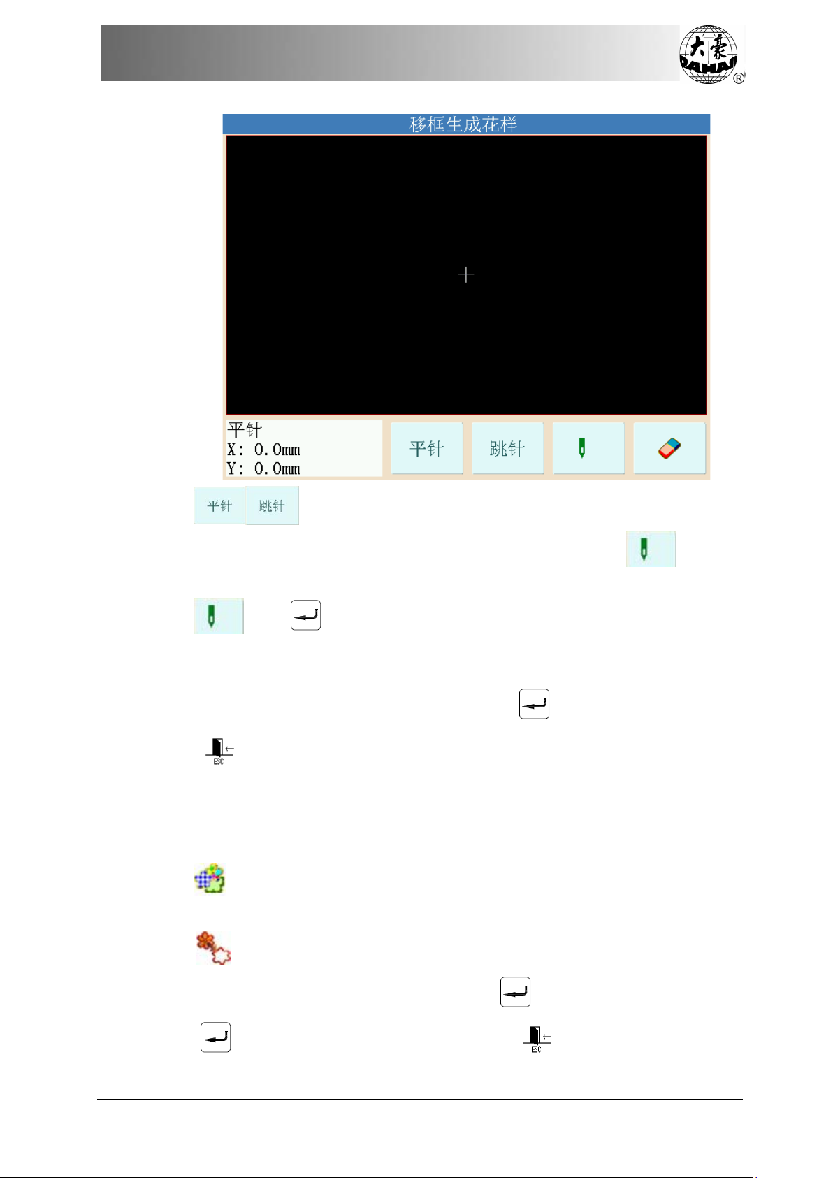
Chapter 4 Memory Pattern Management
4. Press to switch between satin stitch and jump stitch. Press the manual
frame-moving key to move the frame along the desired route, and press at every
turning point to confirm the route.
5. Press and “ ” in order after editing, and system will hint user to input new
pattern number and name.
6. Following the hints, user can input new pattern number (system will automatically
provides a default number) and pattern name, and then press “ ” to confirm for generation.
7. Press “ ” to quit the operation and return to previous interface.
4.16 Generate Outline Pattern from Normal Pattern
This function is to create a new pattern according to the outline of the selected pattern.
1. Press in the main interface, to enter memory pattern management interface.
2. Select pattern in the pattern image area of the memory pattern management interface.
3. Press “ ” to enter the operation interface for generating outline pattern.
4. If user doesn’t want to use the default value, press “ ” to change by keyboard.
5. Press “ ” to generate the outline pattern or press “ ” to quit the operation, and
BECS-D19 User’s Manual
51
Page 62
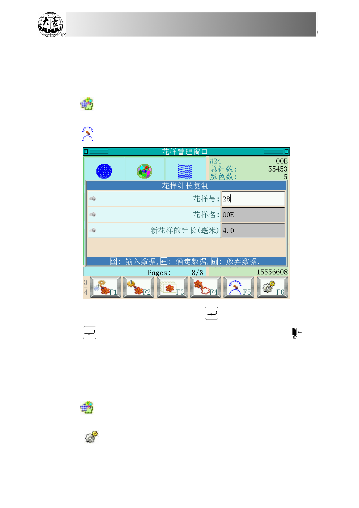
Chapter 4 Memory Pattern Management
then return to the pattern management selection interface.
4.17 Copy Pattern of Varied Stitch Length
This function is used to create pattern with the same shape but different stitch length.
1. Press in the main interface, to enter memory pattern management interface.
2. Select pattern in the pattern image area of the memory pattern management interface.
3. Press “ ” to enter the operation interface for copying pattern of varied stitch length.
If user doesn’t want to use the default value, press “ ” to change by keyboard.
4. Press “ ” to generate a new pattern with different stitch length or press “ ” to
quit the operation, system will return to the pattern operation selection interface.
4.18 Set Common Parameters
Each pattern is attached with its color-changing order and normal parameters such as
scaling, repetition and so on, which can be checked and set here.
1. Press in the main interface, to enter memory pattern management interface.
2. Select pattern in the pattern image area of the memory pattern management interface.
3. Press “ ” to display the embroidery parameter setting interface, if the selected
pattern is the pattern under embroidery. See chapter 5 for details.
52
BECS-D19 User’s Manual
Page 63
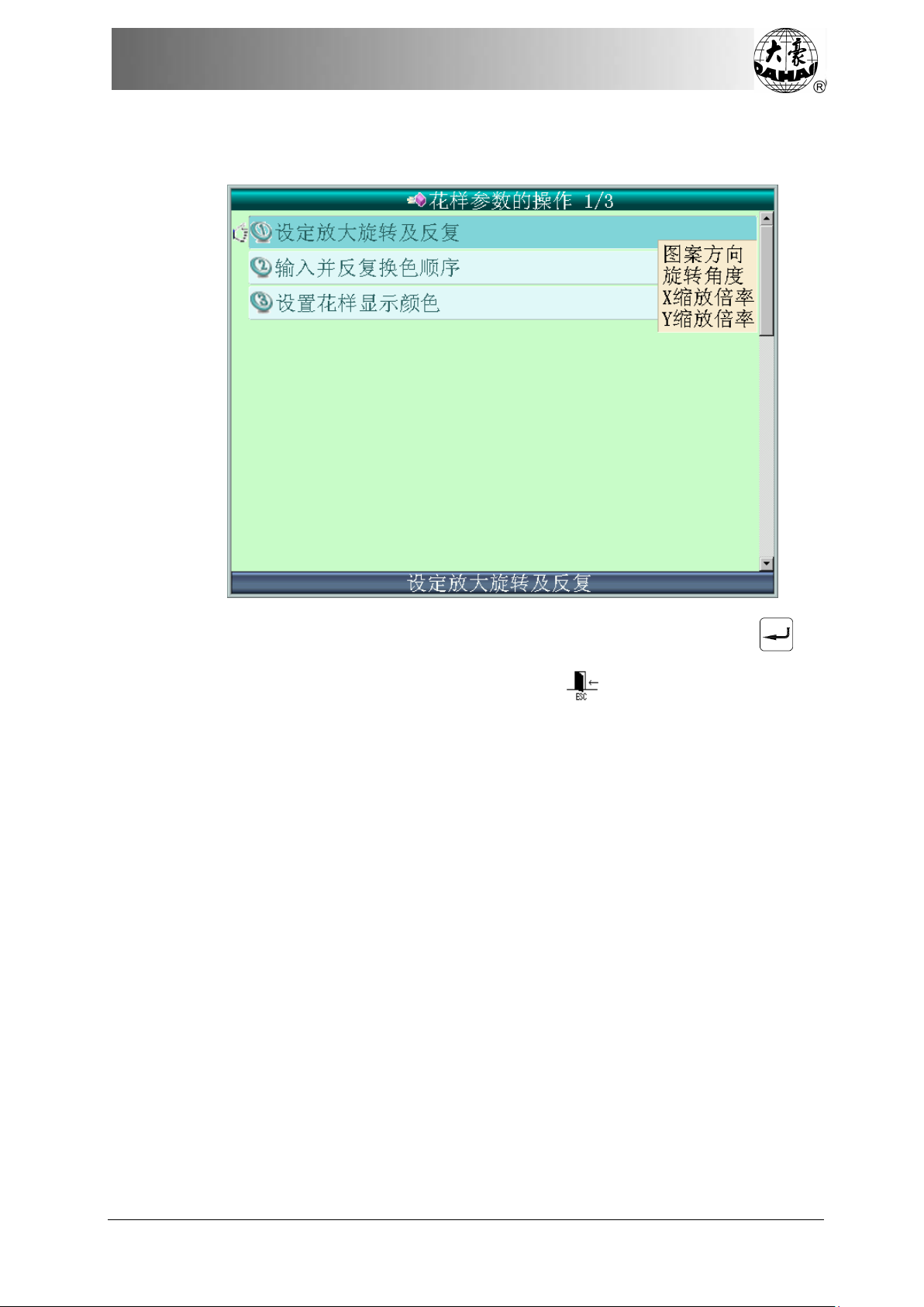
Chapter 4 Memory Pattern Management
If the selected pattern is not the pattern under embroidery, the non-embroidery parameter
setting interface will be displayed.
For setting parameters, please refer to 5.1 and 7.1. After setting, press the key “ ” to
save the parameters with the pattern for future use. Press “ ” to quit saving, system will
return to the pattern operation selection interface.
BECS-D19 User’s Manual
53
Page 64
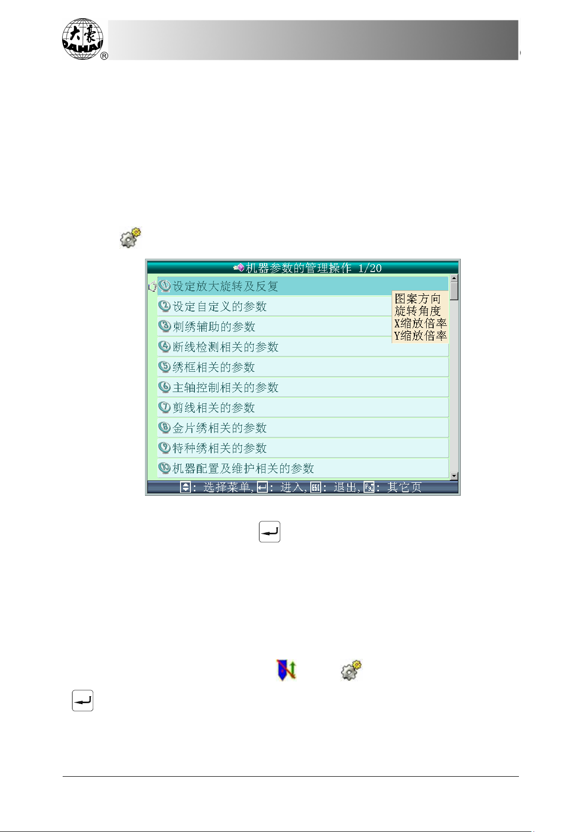
Chapter 5 Machine Parameter Management
Chapter 5 Machine Parameter Management
In this system each pattern has its own settings of the normal parameters (like scaling and
repetition) and color-changing order. When a new pattern is selected, the corresponding normal
parameters and color-changing order that are saved with the pattern will become effective.
This system supports multi-tasks at the same time. So it’s possible to set or change the
normal parameters and color-changing order of patterns not under current embroidery. The
entrance for the operation of those patterns is at the corresponding operation interface under the
memory pattern management interface (See Chapter 4).
Press
As the picture shows, when you move the icon to certain parameter, system will show
in the main interface to enter the following interface:
some parameters (4 at most), and press “ ” to enter the interface for setting that parameter.
5.1 Common Parameter Setting
Common parameters include: “X&Y Scaling”, “Rotating Angle”, “Direction”, “Priority
Mode”, “Repetition Mode”, “Repetition Priority”, “X&Y Repetition” and “X&Y Interval”.
User can control the final embroidery results by adjusting these parameters. That’s why these
parameters are often adjusted when a pattern is selected.
In the embroidery preparation status “ ”, press in the main interface and then
“ ”to enter the common parameter setting interface.
54
BECS-D19 User’s Manual
Page 65

Chapter 5 Machine Parameter Management
The ways to set parameters are similar. This chapter will explain how to set the “X
Scales” as an example and give the definitions of other parameters (Read 5.1.3 as reference).
5.1.1 Pattern Direction
5.1.2 Rotating Angle
This parameter can be used to make the pattern rotate in a certain angle.
5.1.3 Scaling
This parameter controls the scaling rate in horizontal (X) direction, in order to scale
up/down the pattern.
BECS-D19 User’s Manual
55
Page 66

Chapter 5 Machine Parameter Management
1. Press the function item “X Scaling”
Press “X Scaling” in the common parameter interface, and the interface will display the
parameter-setting window.
2. Modify the value of “X Scaling”
Press the number keys in the parameter-setting window to change the scaling in X
direction. User can press to cancel the last input digit. Note: some parameter value is
input by pressing .
3. Press “ ” to save the modification or press “ ” to quit without saving.
5.1.4 Repetition Prio ri ty
There are two modes: X priority and Y priority.
56
BECS-D19 User’s Manual
Page 67

Chapter 5 Machine Parameter Management
5.1.5 Repetition Mode
Currently, system supports normal repetition and part repetition. Normal repetition
means: after embroidering a pattern, system will embroider the same pattern again; part
repetition is based on color, system will move to next color after finishing embroidering one
color in all the patterns.
5.1.6 X-Y Repetitions
X Repetitions set the number of rows in repetition, and Y Repetitions set the number of
columns in repetition. The above diagram shows that X Repetitions is 3 and Y Repetitions is 2.
The largest set value is 99*99.
5.1.7 X-Y Repetition Interval
The above diagram also explains the meaning of this parameter.
5.1.8 Priority Mode
There are two modes: rotating priority and scaling priority. When user has selected the
“Rotating Priority”, the pattern will rotate first and then scale up/down according to the set
parameters. Otherwise it will scale up/down first and then rotate.
5.2 Setting of Other Embroidery Parameters
Other parameters include 8 groups: embroidery assistant parameters, thread-breakage
detection parameters, frame parameters, main shaft parameters, thread-trimming parameters,
sequin parameters, special embroidery parameters and machine configuration & maintenance
parameters. For machines with encryption function, some parameters can be attached with
administrator password or factory password. For setting the administrator passwords and the
factory password, as well as initialization of parameters, please press to enter the
BECS-D19 User’s Manual
57
Page 68

Chapter 5 Machine Parameter Management
“machine authority management” interface. (See 5.3)
Refer to Appendix 1 for details of each parameter.
1. Press in the main interface.
2. System enters the parameter setting interface, where user move cursor to the target
parameter and press “ ” to select and set the parameter.
Note:
1. The number, name and current value of each parameter are displayed in the parameter
list window.
2. For the machine with attached passwords, parameters marked with can’t be
changed unless the administrator password is unlocked; parameters marked with can’t be
changed unless the factory password is unlocked. When a parameter is labeled by a number,
then it can be changed by pressing “ ”.
5.2.1 Setting Procedure for Other Parameters
The setting procedure is similar for all parameters. User can set them according to the
description in this section.
1. Select the parameter group.
Move the cursor to the parameter group to be changed, press “ ” to enter the
parameter setting interface. Move the cursor to the parameter and press “ ” to change.
Make sure the parameter is unlocked if the machine has encryption function (See Chapter 5.3)
For instance, if you want to modify machine stitch count parameter, which is located in
the first item “D01 Needles <1, 15>” of “machine configuration & maintenance parameter”.
2. Press
58
in the main interface, move the cursor to “machine configuration &
BECS-D19 User’s Manual
Page 69

Chapter 5 Machine Parameter Management
maintenance parameter”, press “ ”:
3. Select the parameter to be changed “F21 Cyclic Embroidery Head Shuttle Rebounding
Number <1, 9>” and press “ ” to display the following interface:
4. Input the needle number according to machine type, and press “ ” to save the
setting or press “ ” to quit, system will return to the interface of “machine configuration
& maintenance parameter”
Note: Some parameters can not be inputted, you can only use to select.
BECS-D19 User’s Manual
59
Page 70

Chapter 5 Machine Parameter Management
5.2.2 More Functions for Setting Other Parameters
There are brief introduction of parameters in the Appendix 1. Here are some functions
used in embroidery.
1. Cyclic Embroidery
This function can increase the embroidery efficiency.
When the parameter “To Do Cyclic Embroidery” is set as “Yes”, the cyclic embroidery
function is activated and the icon will appear in the main interface. When this function is
valid, after completing the embroidery of a selected pattern, the machine will automatically
embroider it again without pulling the bar.
Usually, cyclic embroidery accompanies repetition embroidery or specially-designed
patterns, and the parameter “Back to Origin after End” should be also set as “Yes”. Thus when
the machine is embroidering the following cloth-piece, the previous one can be replaced by
user. After embroidering the selected pattern, the frame will automatically return to the start
point and the machine will automatically embroider the previous cloth-piece again and at this
time it’s possible to replace the following one.
2. Save Manual Color-changing
In embroidery confirmation status, user can choose whether to save the manual
color-changing’s needle position into the color-changing order unit. Its purposes are as follows:
1) if mistakes are found at the automatic color-changing order during embroidery, the
color-changing order can be modified with manual color-changing; 2) when a new pattern is
embroidered with manual color-changing once, the color-changing order is set for the pattern.
To use this function, user should set the parameter “Save Manual Color-changing” as
“Yes”. Note: the parameter value will automatically change into “No” at the end of embroidery
of one pattern.
3. Brake Adjustment (A Must for New Machine)
This function is to adjust the control parameters for braking, to adapt to machines with
different mechanical characteristics, which may also change along machine running. Thus this
function can help the machine to work better with the computer. The function depends on two
parameters “Stop Position Compensation” and “Main Motor Parameter”.
To adjust the parameter “Stop Position Compensation” is to adjust the stop position of the
main shaft. When the main shaft often stops at less than 100 degree, user can increase the
parameter value. When the main shaft often stops at more than 100 degree, user can decrease
the parameter value. Thus user can adjust the value to let the main shaft stop close to 100
degree. The value range is between 0 and 30.
To adjust the parameter “Main Motor Parameter” is to adjust cooperation between main
shaft motor and mechanical parts. The parameter value can be set between 0 and 30, and set as
0 in most situations. If during braking the main shaft vibrates without moving or rotates in the
reverse direction, or looks like lacking of brake strength, user can increase the parameter value.
After adjusting these parameters, user can press the task swift key on the panel to return to
the main interface. Press the key and “ ”, to check the effects of the parameter
60
BECS-D19 User’s Manual
Page 71

Chapter 5 Machine Parameter Management
adjustment. If user is not satisfied with the effects, he can press the swift key on the panel to
return to the parameter setting interface, where he can adjust the parameter again. Close the
parameter setting interface in the end.
4. Forbid Pattern Output
The function is to forbid unauthorized copy of patterns from memory (into the disk). If the
machine administrator set “No Output Pattern” as “Yes”, other persons are unable to output the
patterns to the disk. If user needs to output, he has to release the setting of “No Output Pattern”
first.
5.3 Initialize Machine Parameters
This function can initialize the general embroidery parameters of the machine. System
saves a group of default parameter values. The manufacturer and embroidery factory
administrator can save their parameter settings. This operation need follow the rules at below:
1. When the manufacturer password and embroidery factory administrator password are
not set or the machine has no encryption function, all general embroidery parameters are
initialized to their default values.
2. When that manufacturer password has been set and unl ocked, all general embroidery
parameters are initialized to their default values.
3. When that manufacturer password has been set and still locked but administrator
password has not been set or has been released, all manufacturer-authorized machine
parameters are recovered to the values saved by the manufacturer and other parameters are
initialized to the default values.
4. When both manufacturer password and administrator password have been set and still
locked, all manufacturer-authorized machine parameters are recovered to the values saved by
the manufacturer, all administrator-authorized machine application parameters are recovered to
the values set by administrator, and other parameters are initialized to their default values.
5. When that manufacturer password has not been set and administrator password has
been set but unlocked, all general embroidery parameters are initialized to their default values.
6. When that manufacturer password has not been set and administrator password has
been set but still locked, all administrator-authorized machine application parameters are
recovered to the values saved by administrator and other parameters are initialized to the
default values.
5.4 Machine Authorization Management
Note: This operation is fit for the machine with encryption function only.
For the convenient management of machine, general user can’t modify all parameters;
users are divided into three groups: general user, machine administrator and manufacturer user.
General user, having the lowest authorization, can only modify the embroidery parameters of
the machine, while machine administrator can also modify managing parameters, but only the
manufacturer user can modify all parameters.
Press “Machine Authorization Management” to enter the following interface.
BECS-D19 User’s Manual
61
Page 72

Chapter 5 Machine Parameter Management
If the password is set and the machine administrator or the manufacturer user need modify
the parameter, he must input the password before making any change. They can also change
password, save or restore parameters.
5.4.1 Unlock/Change Administrator Password
When the machine is sold by manufacturer, it’s without password, namely user can change
all parameters. After password setting, general user can’t modify the machine application
parameters. The administrator has to input the right password before modification.
1. Press
move the cursor to “unlock/change administrator password”, and press “ ” to enter.
in the main interface to enter machine parameter management interface,
62
BECS-D19 User’s Manual
Page 73

Chapter 5 Machine Parameter Management
2. Move the cursor to “unlock/change password by administrator”, and press “ ” to
input the old password and a new one.
The administrator needs to input the old password and new password one by one. The
machine manufacturer will inform the administrator of the default password which is of 4-9
digits. T o prevent the user’s wrong operation, the new password must be input two times.
5.4.2 Administrator Unlocks the Machine
After machine administrator motifies the password, the machine is locked. General user
can’t modify the machine application parameters. To modify these parameters, the
administrator must input the administrator password or the manufacturer password. The
machine will be locked after power-on at each time.
1. Press
move the cursor to “machine parameter authorization management”, and press “ ” to enter.
2. Move the cursor to “unlock/change password by administrator”, and press “ ”.
in the main interface to enter machine parameter management interface,
BECS-D19 User’s Manual
63
Page 74

Chapter 5 Machine Parameter Management
System displays password input interface.
3. Administrator inputs password
After inputting the password, system becomes unlocked; user can modify related machine
parameters.
5.4.3 Administrator Saves and Recovers Optimized Parameters
Administrator can save and recover related machine parameters. If user wants to save the
currently set parameters, press the key of “administrator saves optimized parameters” to save.
For system can only save one set of parameters, every time optimized parameters are saved, the
previously saved parameters will be covered. If user wants to recover the previously saved
optimized parameters, press the key of “administrator recovers optimized parameters” and
system will hint the operation. User can follow the hint and confirm the operation to recover
the previously saved parameter values.
5.4.4 Change Manufacturer Password
The machine manufacturer can modify all parameters. When the machine is sold, the
machine is unlocked. After password setting, the machine is locked. To change the machine
parameters, you have to input password first. But after you repower the machine, the machine
will be locked again. The details of it are similar to the “Unlock/Change Administrator
Password”.
5.4.5 Unlock Manufacturer Password
The method is similar to that of unlocking administrator password.
5.4.6 Manufacturer Saves and Recovers Optimized Paremeters
The method is similar to that by which administrator saves and recovers parameters.
64
BECS-D19 User’s Manual
Page 75

Chapter 5 Machine Parameter Management
5.5 Initialize Machine Parameters
This function can initialize the general embroidery parameters of the machine. System
saves a group of default parameter values. The manufacturer and embroidery factory
administrator can save their parameter settings. This operation need follow the rules at below:
1. When the manufacturer password and embroidery factory administrator password are
not set or the machine has no encryption function, all general embroidery parameters are
initialized to their default values.
2. When that manufacturer password has been set and unl ocked, all general embroidery
parameters are initialized to their default values.
3. When that manufacturer password has been set and still locked but administrator
password has not been set or has been released, all manufacturer-authorized machine
parameters are recovered to the values saved by the manufacturer and other parameters are
initialized to the default values.
4. When both manufacturer password and administrator password have been set and still
locked, all manufacturer-authorized machine parameters are recovered to the values saved by
the manufacturer, all administrator-authorized machine application parameters are recovered to
the values set by administrator, and other parameters are initialized to their default values.
5. When that manufacturer password has not been set and administrator password has
been set but unlocked, all general embroidery parameters are initialized to their default values.
6. When that manufacturer password has not been set and administrator password has
been set but still locked, all administrator-authorized machine application parameters are
recovered to the values saved by administrator and other parameters are initialized to the
default values.
5.6 Save Machine Parameters to Disk
This function is to save the current software information and machine parameters to disk
for future inquiry or use.
5.7 Read Machine Parameters from Disk
This function is to read data from disk to machine, in order to make use of saved
parameters at any time necessary without reseting them.
5.8 Adjust XY Parameters of Servo Frame
This type of parameters is used for the machine whose main shaft uses Dahao servo motor
and driver. Only the manufacturer can modify these parameters. For machine with encryption
function, you must input the manufacturer password before adjusting the parameters or
performing the corresponding operation to the machine. The operation process is as follows:
1. Press in the main interface.
BECS-D19 User’s Manual
65
Page 76

Chapter 5 Machine Parameter Management
2. System will enter the machine parameter management interface. Move the cursor to
“Adjust XY Parameters of Servo Frame” and press “ ” to enter the interface of “Parameters
of X Servo Drivers”.
3. Input manufacturer password, move the cursor to corresponding item and press “ ”
to do the corresponding operation.
5.8.1 Set Parameters
The setting is similar to that of other normal parameters, please refer to Appendix 1.
5.8.2 Inquire Driver Status
This operation can inquire the Dahao servo driver status. System will display the windows
of X/Y servo driver status after user carries out this operation. User should turn off power and
adjust Dahao servo driver if the following interface appears.
66
BECS-D19 User’s Manual
Page 77
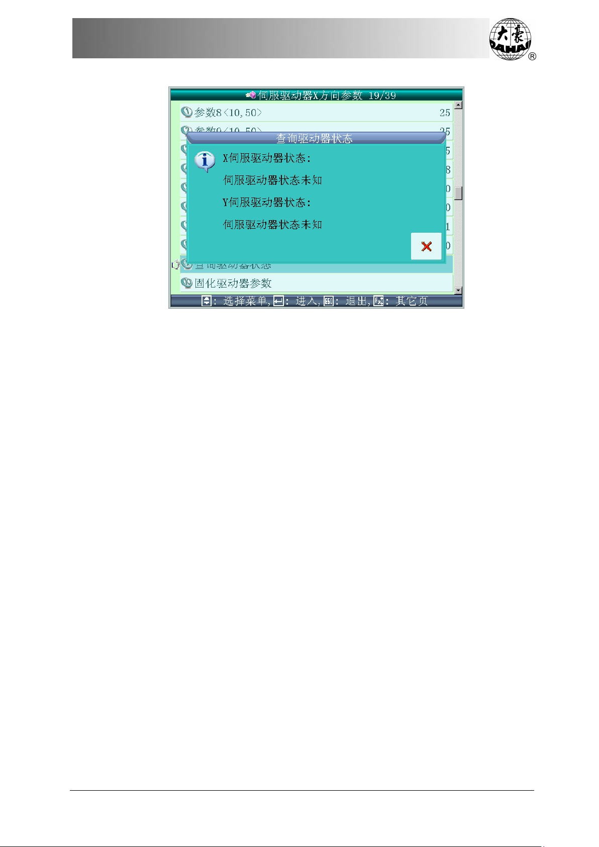
Chapter 5 Machine Parameter Management
5.8.3 Save Driver Parameters
The current settings of parameters for X/Y servo drivers in the controller will be saved
and applied to the servo driver after user performs the operation. And the parameters can be
saved even power is off.
5.8.4 Recover Default Driver Parameters
The X/Y parameters of servo driver in the controller will be restored to their default
values if you operate this function.
BECS-D19 User’s Manual
67
Page 78
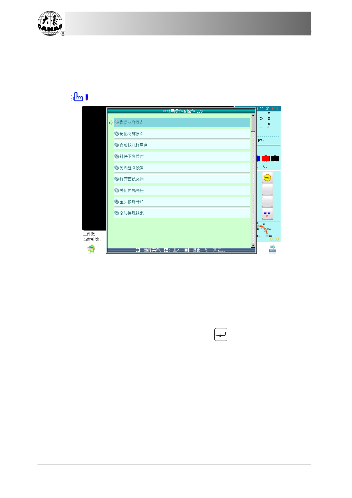
Chapter 6 Assistant Functions
Chapter 6 Assistant Functions
6.1 Assistant Embroidery Operation
Press in the main interface to enter assitant embroidery operation interface.
If the frame origin has been set (see 6.2.3), in the embroidery confirmation status, user can
set pattern start point.
6.1.1 Resume Pattern Origin
If the current pattern has start point, user can use this function to move the frame to the
start point saved before.
1. Follow the above instruction and enter assistant embroidery operation interface.
2. Move the cursor to “Resume pattern origin” and press .
68
BECS-D19 User’s Manual
Page 79

Chapter 6 Assistant Functions
3. Press “ ” to resume start point, then system will move the frame to the start position
that has already been saved before; press “ ”to cancel the operation.
6.1.2 Save Pattern Origin
1. Move the frame to the embroidery pattern origin.
2. Follow the above instruction and enter assistant embroidery operation interface.
3. Move the cursor to “Save pattern origin” and press to display the hint window.
4. Press the key “ ” to save the current frame position as the origin; press “ ” to
cancel the operation.
BECS-D19 User’s Manual
69
Page 80

Chapter 6 Assistant Functions
6.1.3 Pattern Origin Auto Search
This function is used for locating pattern center to the frame software center set by the
system (see 6.2.5) so that you can embroider the pattern at the center of the frame.
1. Follow the above instruction and enter assistant embroidery operation interface.
2. Move the cursor to “Pattern origin auto search” and press .
Press “ ” to confirm, then system will search the centre of frame and move to that
position; press “ ”to cancel the operation.
3. System returns to the main interface.
6.1.4 Needle Stops Down
This function is used for the embroidery of the entire fabric. The needle will stop and
prick into the embroidery cloth to fix it when the machine finishes a part of the embroidery.
After releasing the cloth, user can move the frame to an appointed position. When the cloth is
fixed on the frame again, it is ready for the next operation. This function is only available in
embroidery confirmation status.
1. Follow the above instruction and enter assistant embroidery operation interface.
2. Move the cursor to “Needle stops down” and press .
70
BECS-D19 User’s Manual
Page 81

Chapter 6 Assistant Functions
3. Press “ ” to confirm operation, system lets needle goes down to hold the cloth;
press “ ” to cancel the operation.
4. Release the cloth, move frame and confirm the operation.
After releasing the cloth, user need move frame to appointed position and press “ ” to
confirm. If you press “ ”, the operation will be cancelled.
5. System returns to the main interface.
User can fix the embroidery fabric, operate the main shaft to 100° and then pull bar to
continue embroidering.
BECS-D19 User’s Manual
71
Page 82

Chapter 6 Assistant Functions
6.1.5 Set another Start
Another start point can be set at any point other than the start point. After setting it and
starting embroidery, the frame will firstly move from the other start to the start position
automatically, and then the machine will start normal embroidery. After embroidery, the frame
will move back to the other start. Moreover the other start is also the reference for the frame to
move out when appliqué. This function can only be used u nder the embroidery confirmation
status and before embroidery.
1. Follow the above instruction and enter assistant embroidery operation interface.
2. Move the cursor to “Set another start” and press .
3. Move the frame to the other start.
The system will ask the user to move the frame to the other start and display the
coordinates of X and Y. User need press the frame-moving key to move the frame to the other
start and press “ ” to confirm it, or press “ ” to cancel the operation.
4. System will save the position of the other start and return to the main interface.
6.1.6 Set B Point
This function is optional and the user has to book it advance.
This function is developed to solve the problem of threading inconvenience when
thread-breakage appears on machine with large-scale frame.
When thread breaks, user need press the slow switch to let the machine trim first. Then the
frame will move to the point B. After threading, pull bar to right to let the frame return to the
stop point. Then the embroidery can go on.
A. Setting Procedure
1. Set the absolute origin, see 6.2.3 for details.
2. Follow the above instruction and enter assistant embroidery operation interface.
72
BECS-D19 User’s Manual
Page 83

Chapter 6 Assistant Functions
3. Move the cursor to “Set B Point” and press .
4. Press the manual frame-moving key to move the frame to a proper position.
5. Press “ ” to save B point.
B. Notes
1. When frame returns to the B point, there is only action on Y direction.
2. Frame will not move to the B point everytime when thread breaks at some position
and user presses the slow motion switch.
If the B point is set as in the following picture and the frame only moves above B
point (a zone, that is within the inner edge of the table), the machine will only have the
trimming action instead of moving frame to B point when you press slow motion button after
thread-breakage; only when frame is moving under B point (b zone, that is outside the inner
edge of the table), can the frame move to the B point after you press slow motion switch at
thread-breakage. In case of no action of the frame, please check the machine.
3. The position of the B point should be set as in the following picture, at the upper
edge of table notch, provided that it will not affect the threading operation. The reasons are as
follows:
(1) If B point is above the line, the frame will return t o B point after pressing slow
moving key. There will be a long distance to go to the stop point after threading.
(2) If B point is under the line, threading will be greatly influenced.
BECS-D19 User’s Manual
73
Page 84

Chapter 6 Assistant Functions
1. Frame 2. Best Line for B Point Setting 3. Edge of the Table
6.1.7 Operation of Air Frame, Sequin and Coiling Devices
For the machine equipped with air frame, sequin or coiling devices, user can set that
device via the controller:
1. Follow the above instruction and enter assistant embroidery operation interface.
2. Follow the hints to press corresponding keys.
Note: switch of air valves (V1~V4) are for quilt embroidery. Other sequin and special
embroidery operations are detailed in different chapters.
6.1.8 Upper Thread Holding Operation
The operation is used for the machine having upper thread-holding function. User can
activate or deactivate this function by this operation.
6.2 Other Assistant Management Operation
These operations include machine maintenance, statistic information inquiry and other
system settings.
Press in the main interface to enter the interface for other assistant management
operation, where user can press corresponding keys to realize certain functions.
74
BECS-D19 User’s Manual
Page 85

Chapter 6 Assistant Functions
The interface structure is similar to that of assistant embroidery function. The words on
the keys can help explain their functions.
6.2.1 Check Embroidery P ar ameter
User can check the current pattern’s parameters and some machine conditions.
1. Press in the main interface to enter the interface of other assistant
manangement operation.
2. Move the cursor to “check embroidery parameter” and press “ ”.
3. System will display parameters of current pattern.
These parameters include: pattern number, total embroidery stitch, free memory, cyclic
BECS-D19 User’s Manual
75
Page 86

Chapter 6 Assistant Functions
embroidery, frame origin, soft frame limit and another start point. Press to clear total
embroidery stitch. Af ter viewing paremeters, press “ ” to return.
6.2.2 Check Statistic Data
1. Press in the main interface to enter the interface of other assistant
manangement operation.
2. Move the cursor to “check statistic data” and press “ ”.
3. System displays the statistic data interface.
In the above interface, the statistic data is displayed in chart. User can press to
clear the value and press “ ” to return.
6.2.3 Frame Protection Setting/Frame Origin Sett i ng
Setting the frame origin is the premise for saving the pattern origin and setting frame
protection at power-off. So after machine installation or maintenance, it’s necessary to set the
frame origin.
1. Press in the main interface to enter the interface of other assistant
manangement operation.
2. Move the cursor to “check statistic data” and press “ ”.
76
BECS-D19 User’s Manual
Page 87

Chapter 6 Assistant Functions
3. Press to select “manual frame origin” or “auto frame origin”.
4. Press “ ” to confirm or press “ ” to return.
Before setting auto frame origin, user need move the frame to the desired origin position
and press “manual frame origin”. Then system will save the current frame position as the origin.
In case of emergency stop due to malfunctions or something unusual like unexpected power off,
the machine will cancel saving the origin to avoid mistakes caused by the inaccuracy of
“manual frame origin”. If the frame has been moved or the machine has been maintained after
power off, user should set “manual frame origin” again.
If you hope the system automatically set the frame origin, press “auto farme origin”, and
the system will move the frame automatically and set the origin according to the limit switch.
So please ensure that the effective limit switch has been installed into the machine.
6.2.4 Frame Recovery
In case that frame ha s been moved after power off, this operation can be used to restore
frame position be fore the power-off. The proper performance of this operation is based on the
“frame protection setting/frame origin setting”. In addition, if the power is off in the process of
embroidery and the frame has not been moved, user can directly pull the operation bar to
continue embroidery when power is on again.
1. Press in the main interface to enter the interface of other assistant
manangement operation.
2. Move the cursor to “frame resume” and press “ ”.
BECS-D19 User’s Manual
77
Page 88

Chapter 6 Assistant Functions
3. Press “ ” to confirm or press “ ” to return.
If “auto frame origin” i s set in “frame origin setting”, the frame wil l automatically move
to the frame origin and then back to embroidering position before power-off. It will be invalid
if the “frame origin setting” is set as “manual frame origin”.
6.2.5 Set Embroidery Scope in Software
This function is to set embroidery scope in software and make system embroider pattern
in the set range. It’s the basis to locate pattern in the central place of the frame.
1. Press in the main interface to enter the interface of other assistant
manangement operation.
2. Move the cursor to “set embroidery scope in software” and press “ ”.
3. If software protection has been set, system will ask user to clear original settings.
4. Press “ ” to set the coordinates of top-right corner.
78
BECS-D19 User’s Manual
Page 89
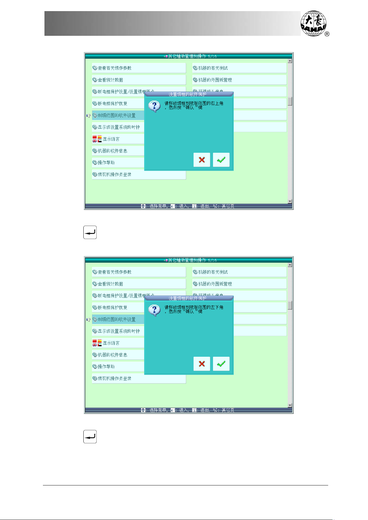
Chapter 6 Assistant Functions
Use frame-moving key to move the frame, after you confirm the top-right corner of soft
limit, press “ ” to confirm.
5. Move frame and input the coordinates of bottom-left corner.
Use frame-moving key to move the frame, after you confirm the bottom-left corner of soft
limit, press “ ” to confirm.
5. System will save the frame software protection.
BECS-D19 User’s Manual
79
Page 90
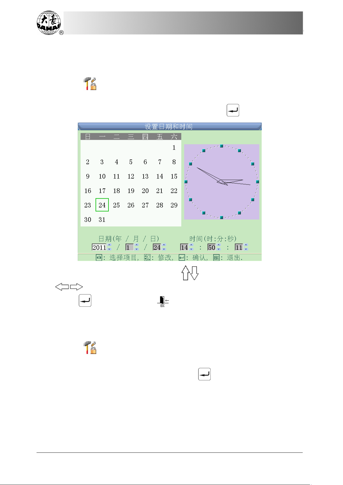
Chapter 6 Assistant Functions
6.2.6 Set System Clock
In date and time interface, user can check and modify the current date and time.
1. Press in the main interface to enter the interface of other assistant
manangement operation.
2. Move the cursor to “display or set system clock” and press “ ”.
3. Use number keys to input number or press to select the number to be inputted;
press to select option.
4. Press “ ” to confirm or press “ ” to return without saving.
6.2.7 Select Language
System supports Chinese, English, Spanish, Turkish and various other languages.
1. Press in the main interface to enter the interface of other assistant
manangement operation.
2. Move the cursor to “display language” and press “ ”.
80
BECS-D19 User’s Manual
Page 91
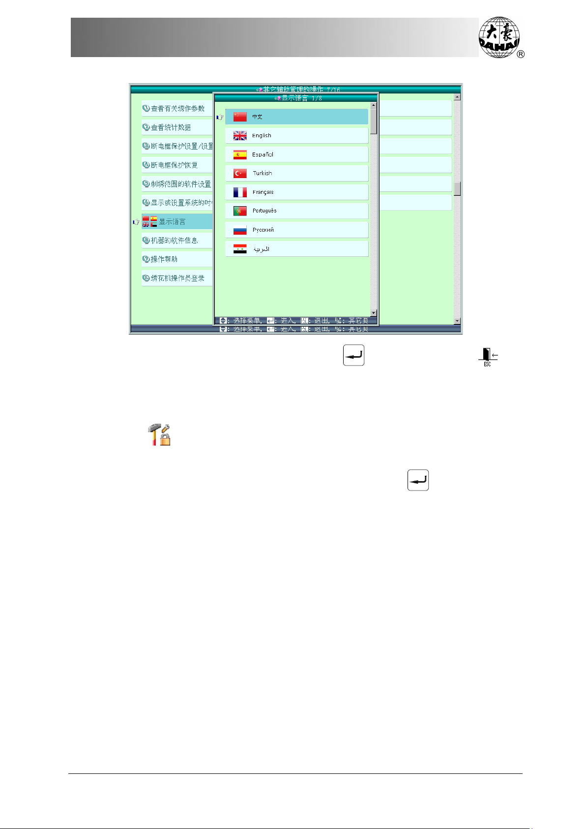
Chapter 6 Assistant Functions
3. Move the cursor to the intended language, press “ ” to confirm or press “ ” to
quit.
6.2.8 Machine Software Information
1. Press in the main interface to enter the interface of other assistant
manangement operation.
2. Move the cursor to “machine software information” and press “ ”.
BECS-D19 User’s Manual
81
Page 92

Chapter 6 Assistant Functions
This function is used for checking the software and hardware information of upper and
lower computor, press “ ” to quit.
6.2.9 Help
This function is to display the help information of the interface.
1. Press in the main interface to enter the interface of other assistant
manangement operation.
2. Move the cursor to “machine software information” and press “ ”.
System will display the help information of the interface, press “ ” or press
to turn page.
6.2.10 Machine Test
This operation is limited to maintenance engineers only. Embroidery workers are
prohibited to use this operation. This operation contains some mechanical work. Please pay
attention to personal and equipment safety.
This function is mainly used for machine test, maintenance and problem diagnosis,
including:
Test optical encoder
Main shaft auto test
82
BECS-D19 User’s Manual
Page 93

Chapter 6 Assistant Functions
Rotate main shaft to fixed angle (from 100°)
Test the pull-bar
Test the limit switches
Test the head solenoids
Test trimming solenoid/ motor
Test holding solenoid
Test hook solenoid/motor
Test catching solenoid/motor
Splay Scissor’s Angle
Trimming motor to search origin
Test thread breakage
Thread Breakage Statistics
Count of Roller Thread Breakage Device
Test sequin device on/off
Sway Zig Rod to 100°
Test lift of taping presser foot
Test upper thread holding function
Thread loosing position adjustment
Needle height position adjustment
Cyclic embroidery color-changing position adjustment
Test D-axis motor
Test H-axis motor
Test chained main shaft rotation speed
Test chained main shaft encoder
Test chained trimming motor
Test chained loosing motor
Detect thread breakage of cyclic embroidery test
BECS-D19 User’s Manual
83
Page 94

Chapter 7 Other Operations
Chapter 7 Other Operations
7.1 Color-changing Order Operation
The pattern’s color-changing order will be saved along with the pattern.
Press in the main interface, to enter color-changing order interface, where user can
make the color-changing order operation.
7.1.1 Input and Repeat Color-changing Order
1. In the color-changing order operation interface, move the cursor to “input and
repeat color-changing order” and press “ ” to enter the interface.
84
BECS-D19 User’s Manual
Page 95
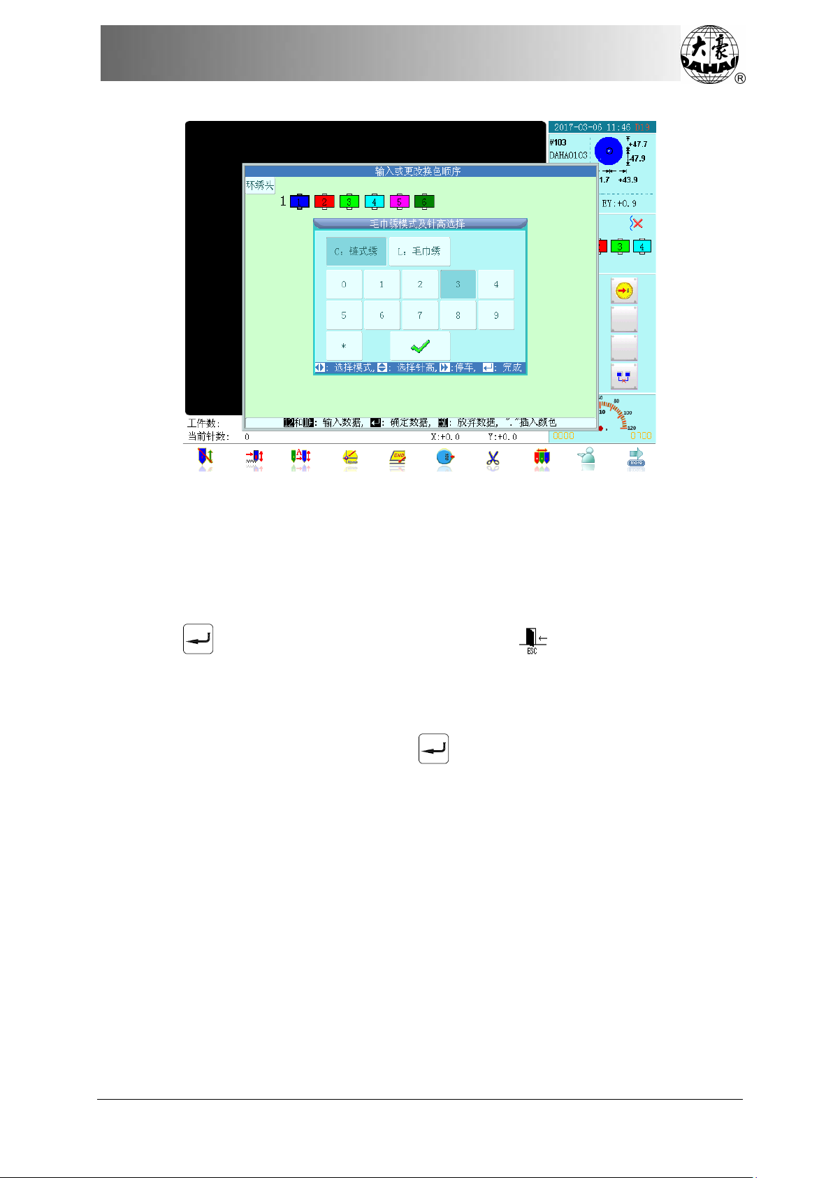
Chapter 7 Other Operations
2. Press number keys on the keyboard (note: the number you input shall not be
larger than the needle number) and input the color-changing position. The
color-changing position and their relative order will be displayed in the interface.
If it is a special embroidery position or sequin embroidery position, the system will enter
the selection window of sequin and special embroidery. For details, please refer to operations
in related chapters.
Press “ ” to save the color-changing order or press “ ” to exit without saving.
7.1.2 Modify Color-changing Order
1. In the color-changing order operation interface, move the cursor to “modify
color-changing order” and press “ ” to enter the interface.
BECS-D19 User’s Manual
85
Page 96

Chapter 7 Other Operations
2. Press the key “ ” to select the position to be modified. Press number
keys on the keyboard to input needle position (if you input a special embroidery
or a sequin embroidery position, see related chapters for details.)
If you want to modify the next color, you can repeat step “2”. Press “ ” to save the
color-changing order or press “ ” to exit without saving.
7.1.3 Replace Color-changing Needle Position
1. In the color-changing order operation interface, move the cursor to “replace
color-changing position” and press “ ” to enter the interface.
86
BECS-D19 User’s Manual
Page 97
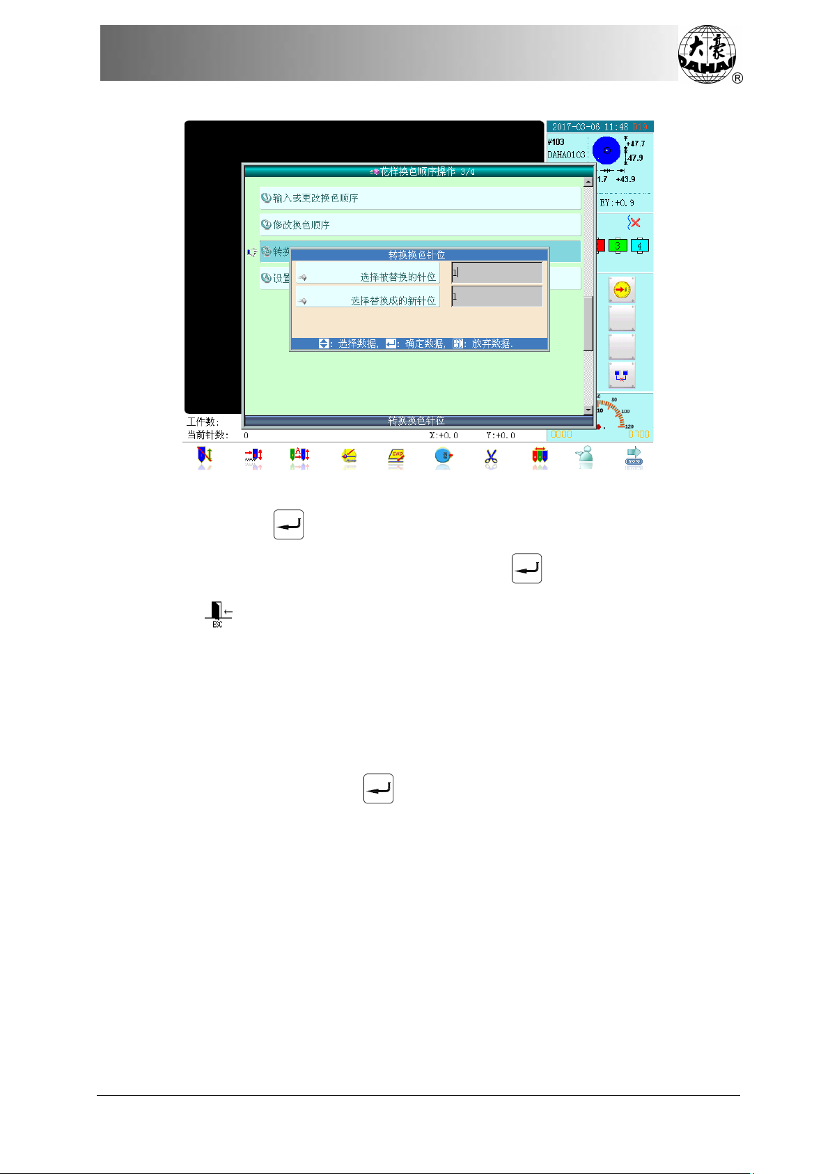
Chapter 7 Other Operations
2. Press number keys on the keyboard to input “the needle position to be replaced”
and press “ ” to confirm and enter the item “new needle position to be
replaced by”. Then, press number keys and “ ” to save the input or press
“ ” to quit without saving.
7.1.4 Set Pattern Disp l a y C olor
In order to make the display effect close to the real embroidery pattern, the system
supports setting of each needle bar color. The needle bar color can be saved with the
color-changing order.
1. In the color-changing order operation interface, move the cursor to “set pattern
display color” and press “ ” to enter the interface.
BECS-D19 User’s Manual
87
Page 98

Chapter 7 Other Operations
There are altogether 40 different default colors for you to choose.
2. First you should press to select the needle bar to be set, then press
“ ” to select the desired color and press“ ” to confirm. After
setting, the corresponding color will be displayed at the needle button.
3. After setting, press “ ” to save the needle bar color setting and return, or press
the key “ ” to return without saving.
7.2 Pattern Border Operation
Press in the main interface, to enter pattern border operation interface.
88
BECS-D19 User’s Manual
Page 99

Chapter 7 Other Operations
7.2.1 Check the Pattern Border Range
This function is to check and display the border range of the current embroidery pattern.
1. Move t he cursor to “check the pattern border” and press “ ”. System will display
the border information of the pattern in window:
2. Press “ ” or “ ” to close the window.
7.2.2 Move the Frame along the Pattern Border
This function can drive the frame move along the border. If it touches any limit, system
BECS-D19 User’s Manual
89
Page 100

Chapter 7 Other Operations
will make automatic correction to avoid collapse with frame during embroidery.
1. Move the cursor to “move the frame along the pattern border” and press “ ”.
System will hint confirmation box.
2. Press “ ” to confirm and move the frame along the pattern border and the
interface will display the movement information. Press “ ” to cancel.
3. After finishing the movement, system will return to the pattern border operation
interface.
7.2.3 Generate Pattern from Pattern Outline
This operation can generate a new pattern from the outline of the current pattern.
90
BECS-D19 User’s Manual
 Loading...