

Daewoo WP-811 Service Manual

S/M No: TWP811MEF0
Service Manual
Colour Television 66 Cm WIDE STEREO
CHASSIS : WP-811
MODEL :DTW - 28W2F
DTW - 2810F
Specifications
CRT
SYSTEM
MAIN VOLTAGE
POWER CONSUMPTION
SOUND OUTPUT
SPEAKER
ANTENNA IMPEDANCE
TUNING SYSTEM
TUNER
NUMBER OF PROGRAM
AUX. TERMINAL
REMOTE CONTROL
TELETEXT
OSD LANGUAGE
28" : W66ECK001X44
PAL / SECAM-B/K, PAL-I/I', SECAM-L/L', NTSC-3.58/4.43 (Play back)
230V AC, 50Hz
Stand-by mode : 2.0 Watts
Normal operating mode : 100 Watts
10 + 10 Watts, 10% THD at RF 60% mod. (1 kHz )
12W 8 ohm x 2 EA
75 ohm unbalanced input ( Din Standard )
Frequency Systhesize (FS) Tuning System
DT5-BF14D
100 program
21 pin EURO-SCART jack (AV input, TV output, RGB input)
21 pin EURO-SCART jack (AV input, S-VHS input)
RCA type AV input jack
Headphone jack (3.5 mm )
JACK AUDIO TERMINAL (AUDIO OUT L, R)
R-22D05(or R-23D05) with 2 "AAA" type batteries
TOP(5 Page memory) & FLOF(7 Page memory)
- West option : English, German/Dutch/Flemish, French, Italian, Spanish/Portuguese,
Swedish/Finnish/Danish, Hungarian, Rumanian, Turkish
- East option : Polish, Czech/Slovak, Rumanian, Servo-croat, German/Dutch/Flemish,
French, Estonian, Lettish
- West : English, German, French, Italian, Spanish, Nethelands, Swedish
- East : English, Russian, Polish, Rumanian, Czech, Hungarian
DAEWOO ELECTRONICS CO., LTD
http://svc.dwe.co.kr JUN.2000

TABLE OF CONTENTS
SAFETY INSTRUCTION .................................................................................................................. 2
SPECIFICATIONS ............................................................................................................................ 3
CIRCUIT BLOCK DIAGRAM ........................................................................................................... 4
ALIGNMENT INSTRUCTION ........................................................................................................... 5
SCHEMATIC DIAGRAM .................................................................................................................. 11
EXPLODED VIEW ............................................................................................................................ 13
PRINTED CIRCUIT BOARD ............................................................................................................ 15
SERVICE PARTS LIST .................................................................................................................... 16
APPENDIX (" Appendix is provided only by internet [http://svc.dwe.co.kr] ")
IC DESCRIPTION ............................................................................................................................. 1
IC DC VOLTAGE CHARTS .............................................................................................................. 18
1

SAFETY INSTRUCTION
WARNING
X-RAY RADIATION PRECAUTION
1. Excessive high voltage can prodece potentially hazardous X-RAY RADIATION. To avoid such hazards,
the high voltage must not exceed the specified limit.
The nominal value of the high voltage of this receiver is
25-27kv at max beam current. The high voltage must
not, under any circumstances, exceed 30kv.
Each time a receiver require servicing, the high volt-
age should be checked. It is imprortant to use an accurate and reliable high voltage meter.
: Only competent service personnel may carry out work involving the testing or repair of this equipment
2. The only source of X-RAY Radiation in this TV receiver
is the picture tube. For continued X-RAY RADIATION
protection, the replacement tube must be exactly the
same type tube as specified in the parts list.
SAFETY PRECAUTION
1. Potentials of high voltage are present when this
receiver is operating. Operation of the receiver outside
the cabinet or with the back board removed involves a
shock hazard from the receiver.
1) Servicing should not be attempted by anyone who is
not thoroughly familiar with the precautions necessary when working on high-voltage equipment.
2) Dischange the high potential of the picture tube
before handling the tube. The picture tube is highly
evacuated and if broken, glass fragments will be
violently expelled.
PRODUCT SAFETY NOTICE
Many electrical and mechanical parts in this have
special safety-related characteristics. These characteristics are often passed unnoticed by a visual
inspection and the X-RAY RADIATION protection
afforded by them cannot necessarily be obtained by
using replacement components rated for higher voltage, wattage, etc. Replacement parts which have
these special safety characteristics are identified in
this manual and its supplements, electrical compo-
2. If any Fuse in this TV receiver is blown, replace it with
the FUSE specified in the Replacement Parts List.
3. When replacing a high wattage resistor ( oxide metal
film resistor ) in circuit board, keep the resistor 10mm
away from circuit board.
4. Keep wires away from high voltage or high temperature components.
5. This receiver must operate under AC230 volts, 50Hz.
NEVER connect to DC supply or any other power or
frequency.
nents having such features are identified designated
symbol on the parts list.
Before replacing any of these components, read the
parts list in this manual carefully. The use of substitute
replacement parts which do not have the same safety
characterisitics as specifide in the parts list may create
X-RAY Radiation.
2
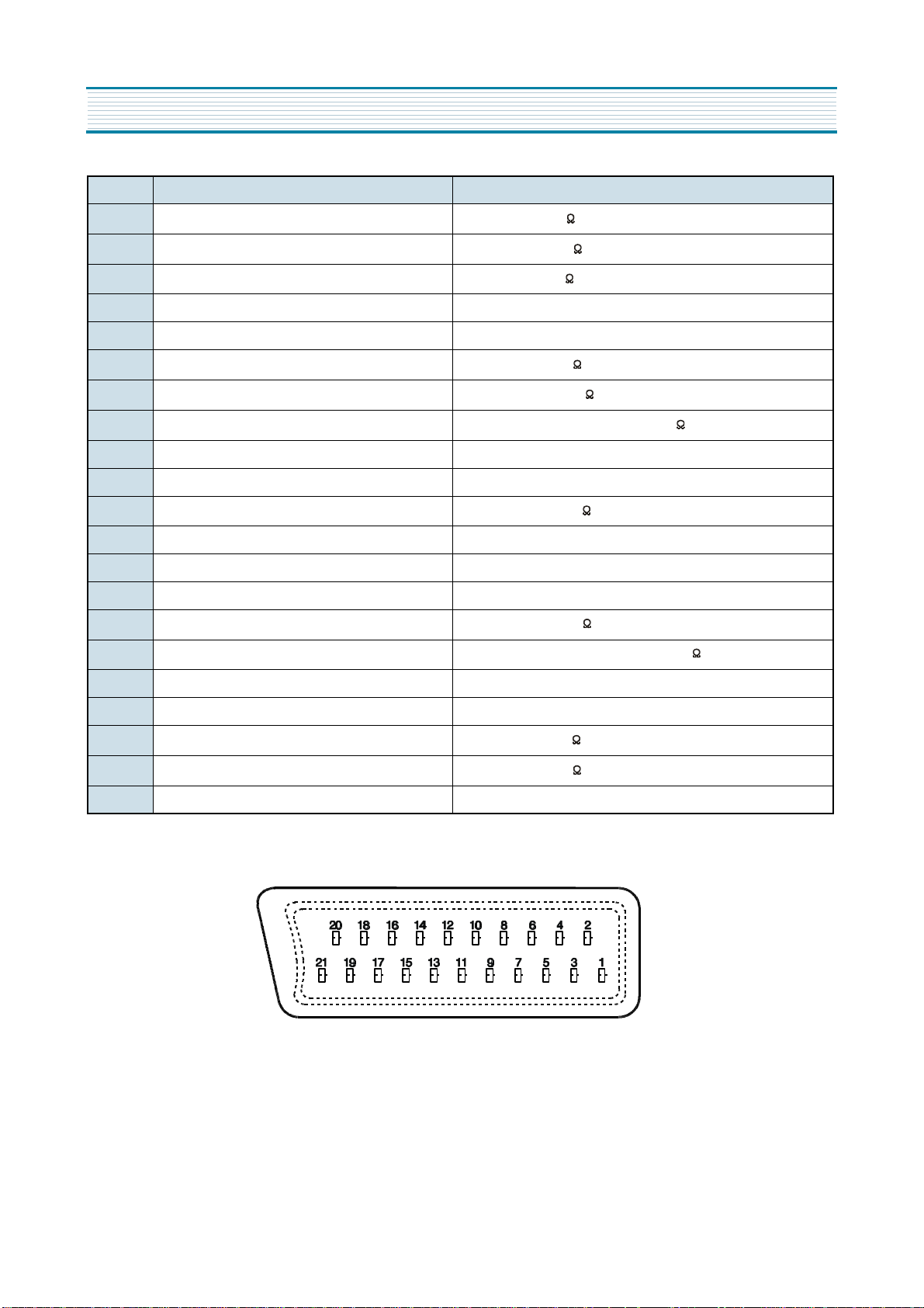
SPECIFICATIONS
PIN Signal Designation Matching Value
1 Audio Out (linked with 3)
2 Audio In (linked with 6)
3 Audio Out (linked with 1)
4 Audio Earth
5 Blue Earth
6 Audio in (linked with 2)
7 Blue in
8 Slow (Function) Switching
9 Green Earth
10 NC
11 Green In
12 NC
13 Red Earth
14 Rapid(Blanking) Switching Earth
15 Red In, C In
16 Rapid(Blanking) switching
0.5Vrms, Imp < 1 k (RF 60% MOD)
0.5Vrms, Imp < 10 k
0.5Vrms, Imp < 1 k (RF 60% MOD)
0.5Vrms, Imp < 10 k (RF 60% MOD)
+
0.7Vpp 2dB, Imp 75
-
TV : 0-2V, PERI : 9.5 - 12V, Imp > 10 k
+
0.7Vpp 2dB, Imp 75
-
+
0.7Vpp 2dB, Imp 75
-
Logic 0 : 0 - 0.4V, Logic 1 : 1 - 3V, Imp 75
17 Video Earth
18 Rapid Blanking Earth
19 Video Out
20 Video In, Y In
21 Common Earth
+
1Vpp 2dB, Imp 75
-
+
1Vpp 2dB, Imp 75
-
3
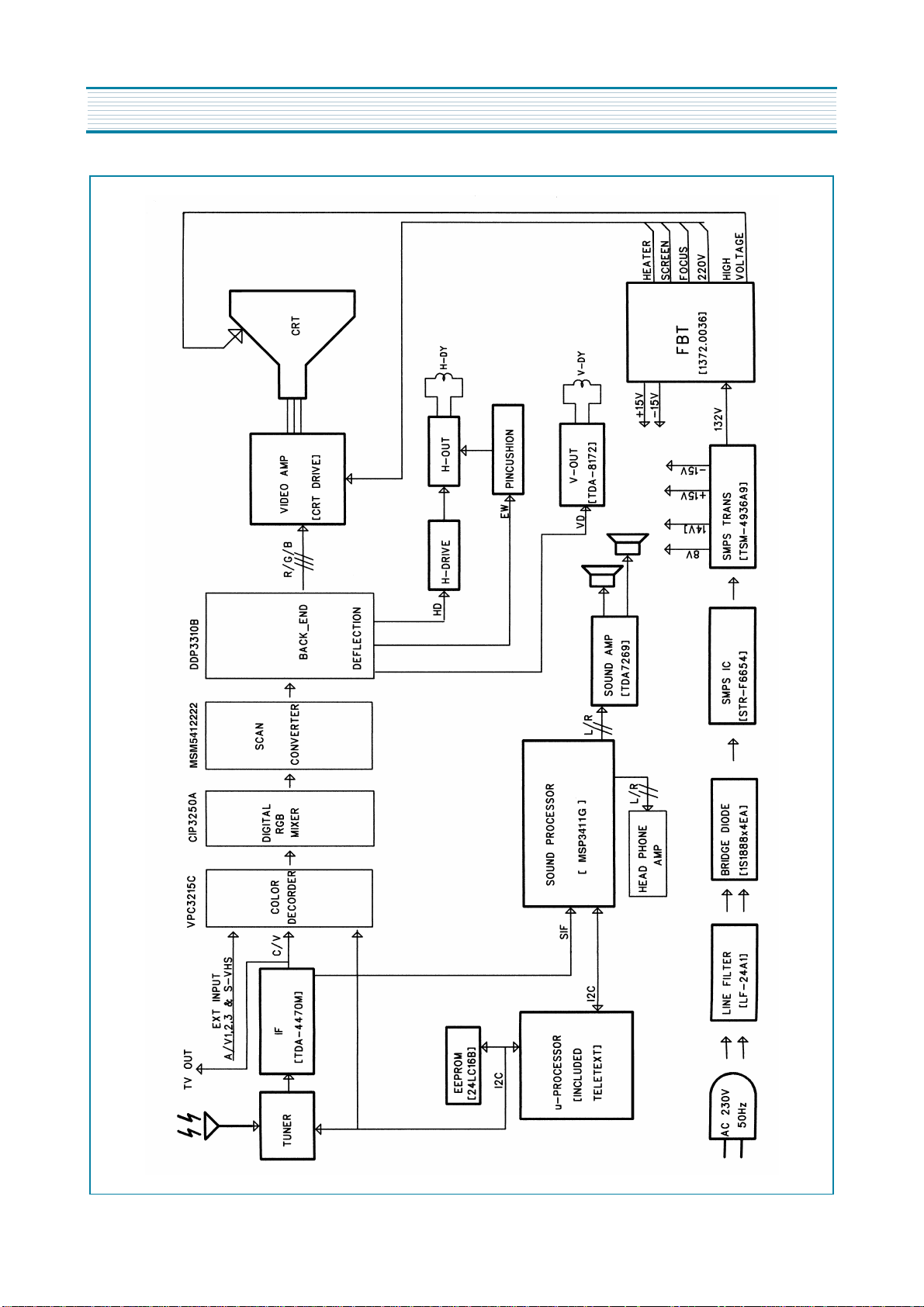
CIRCUIT BLOCK DIAGRAM
4
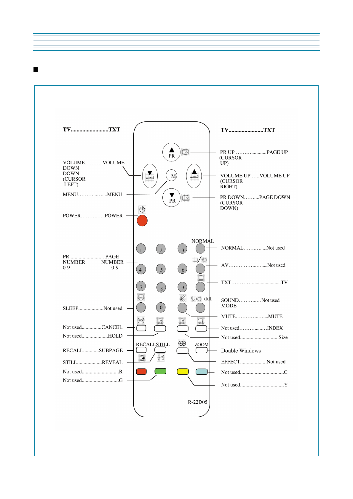
ALIGNMENT INSTRUCTIONS
User Remocon
1. R-22D05
5
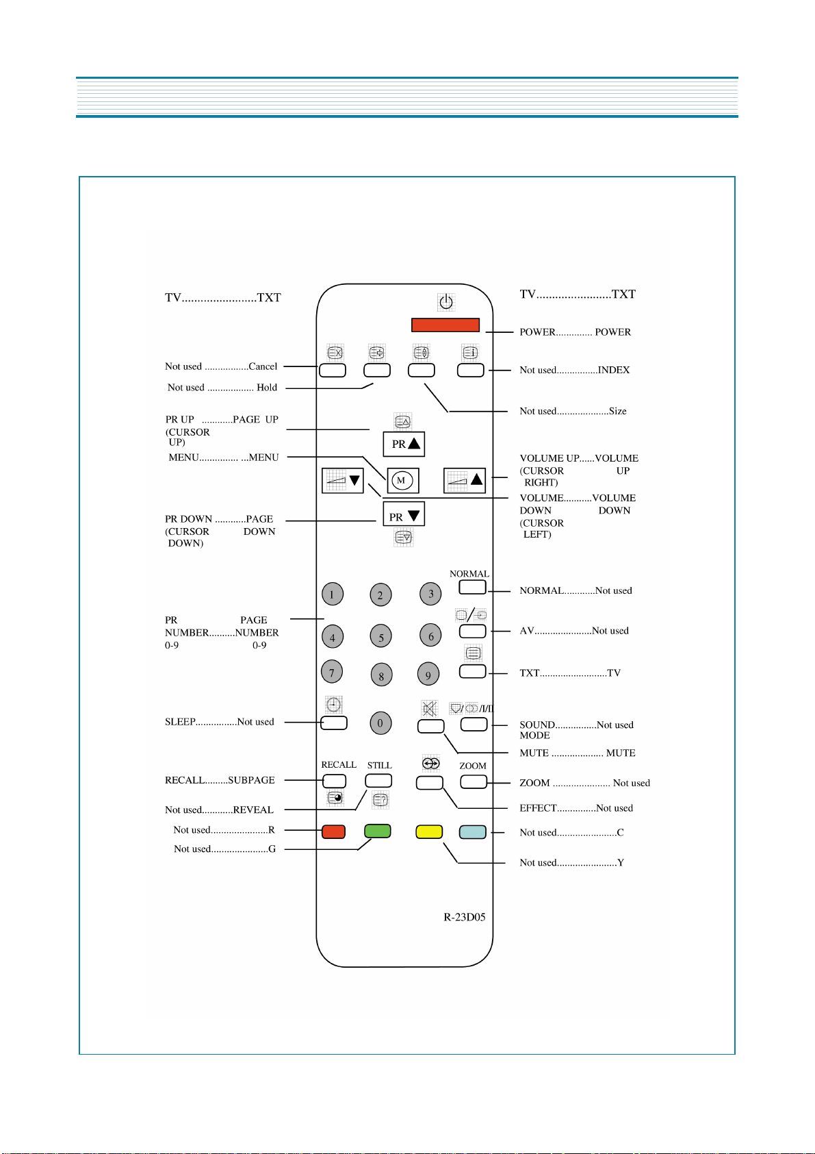
ALIGNMENT INSTRUCTIONS
2. R-23D05
6
ALIGNMENT INSTRUCTIONS
* How to Enter the “ Service Mode ” with user remocon.
1) Set the TV Pr 91
2) Sharpness “ MIN “ control.
3) Red, Green, Yellow buttons in regular sequency within 5 seconds after setting TV power off.
4) You can see the Menu of “ service mode “ on the screen.
5) The PR UP/DOWN buttons on the remote controller are used to move the selection bar up or down the Menus.
6) The VOL UP/DOWN buttons on the remote controller are used to adjust levels.
7) If you want to exit from “ Service Mode “ then power the TV off.
SVC v1
V. Slope
V. Center
V. Size
S. Curve
H. Center
H. Width
EW. Para
EW. Cor T
EW. CB
EW.Sym
R. b
G. b
B. b
R. d
G. d
B. d
G2
Sub Bri
DT
Wide
005
995
220
019
-190
510
382
028
500
021
370
311
311
330
315
330
330
021
048
Yes
- You can see the SVC Menu by OSD in TV set.
7

ALIGNMENT INSTRUCTIONS
AFT
Standard B/G, D/K, I and L
1) Set a Signal Generator with
- RF FREQUENCY = 38.9 MHz,
- RF OUTPUT LEVEL = 80 5dBuV
- Pattern = Color Bar
- System = PAL-B/G
2) Connect the Signal Generator RF Output to TP2 (Tuner IF Output).
There must be no signal input to the tuner.
3) Set the L109 to TP1(I101, #22) with DC Voltage to 2.5V 0.1V
+
-
+
-
AGC
1) Set a Pattern Generator with RF LEVEL 60 3dBuV, RF Frequency 210. 25MHz(10CH), Pattern Color Bar.
2) Connect a OSCILLOSCOPE PROBE to P101 (TUNER AGC INPUT).
3) Set the RBOI to P101(Tuner AGC Input) with DC Voltage to 2.8V 0.2V
+
-
+
-
SCREEN (G2)
1) Set a Pattern Generator with - RF Frequency : 210.25MHz (10CH)
- Pattern : RETMA
2) Select the “G2” in Menu
3) And a Horizontal Line will appear on the screen.
4) Adjust the SCREEN VOLUME on FBT barely to see the Horizontal Line.
5) Press the PR UP/DOWN keys to finish the SCREEN adjustment.
FOCUS
1) Apply a RETMA PATTERN signal.
2) Adjust the FOCUS VOLUME on FBT to obtain optimal resolution.
GEOMETRY
1. VERTICAL SLOPE ( Fixed : Adjust if need be )
1) Apply a RETMA PATTERN Signal.
2) Set the TV to Normal I mode.
3) Adjust the higher semicircle and the lower semicircle to be the same, with the V.Slope
by volume Up/Down keys.
2. VERTICAL CENTER
1) Apply a RETMA PATTERN Signal.
2) Set the TV to Normal I mode.
3) Adjust the center of the picture with the V.Center by volume Up/Down keys.
8
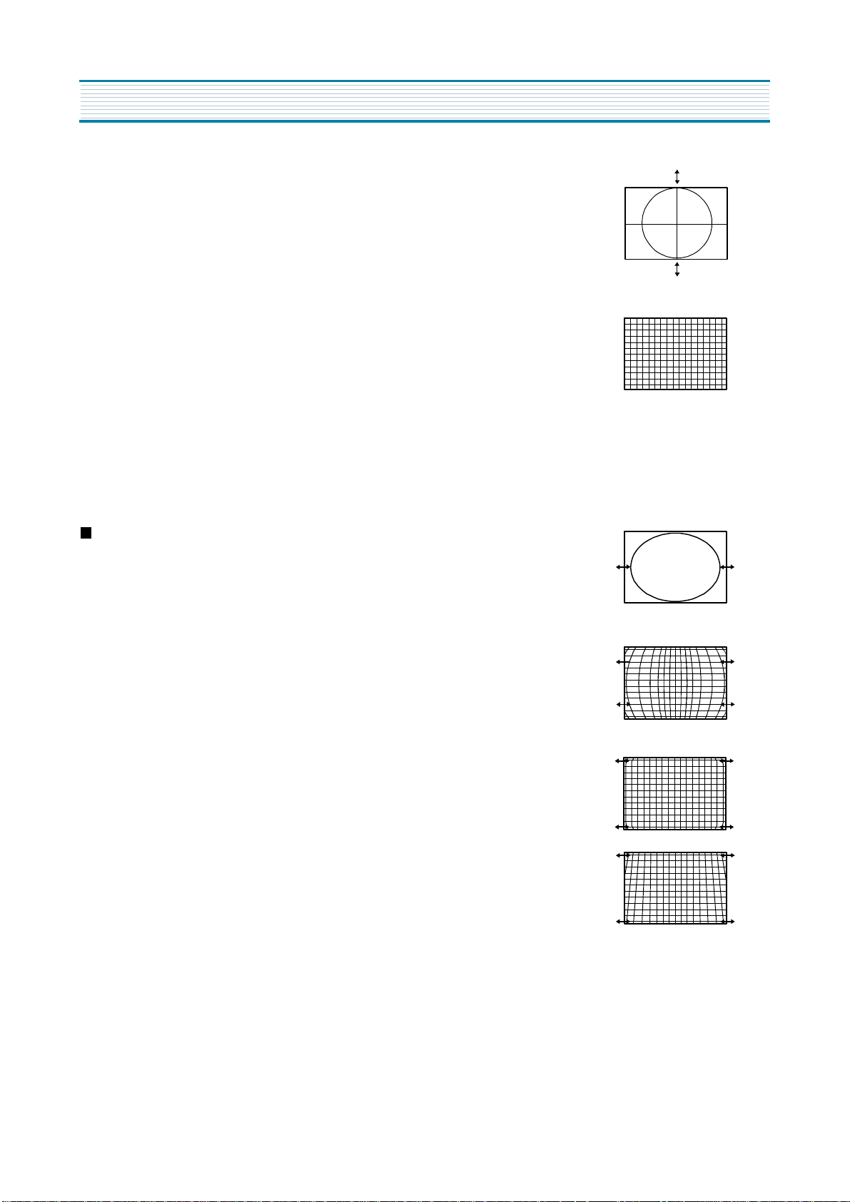
3. VERTICAL SIZE
* The VERTICAL CENTER adjustment has to be done in advance.
1) Apply a RETMA PATTERN Signal.
2) Set the TV to Normal I mode.
3) Adjust the VERTICAL SIZE of the picture with the select V.size by
volume UP/DOWN keys.
4. VERTICAL S-CORRECTION ( Fixed : Adjust if need be )
1) Apply a CROSSHATCH PATTERN Signal.
2) Adjust the S-CORRECTION to obtain the same distance between
horizontal lines with the S.Curve by volume UP/DOWN keys.
5. HORIZONTAL CENTER
1) Apply a RETMA PATTERN Signal.
2) Adjust picture centering with the select H.Center by volume UP/DOWN keys.
ALIGNMENT INSTRUCTIONS
EW
1. WIDTH
1) Apply a RETMA PATTERN Signal.
2) Adjust the horizontal width to make a perfect circle with the select H.Width
by volume UP/DOWN keys.
2. PARA
1) Apply a CROSSHATCH PATTERN Signal.
2) Adjust the vertical line to straight with the select E.W Para by volume
UP/DOWN keys.
3. CORNER ( Fixed : Adjust if need be )
1) Apply a CROSSHATCH PATTERN Signal.
2) Adjust the vertical line to straight with the select EW.Cor T by volume
UP/DOWN keys.
4. SYMMETRY ( Fixed : Adjust if need be )
1) Apply a CROSSHATCH PATTERN Signal.
2) Adjust the symmetrical balance to be suitable with the select EW Sym by
volume UP/DOWN keys.
9

ALIGNMENT INSTRUCTIONS
WHITE BALANCE
1. RGB Reference R
2
2. Beam Reference LOW ( 288, 301 : 10Cd/ )
HIGH ( 288, 301 : 10Cd/ )
m
m
2
3. Adjust G, B Gain with select Menu G,B of BIAS, DRIVE of select Menu so that R, G, B Bars
are on the center position of the analog meter. If R Analog meter is not on center, control
the Brightness +/- of user Remocon so as R Analog meter to be on the center position.
SUB BRIGHT
1. Pattern : Retma
2. Adjust the SUB BRIGHT with the select Sub Bri by volume UP/DOWN keys.
so that only H-Center parts of picture can be seen.
DOUBLE TEXT CENTER
1. Pattern : Pattern RED
2. Select Menu
3. Select DT in SVC menu time to see the Double Text Picture.
( Left : RF Picture, Right : Text Picture )
4. Change the Double Text control keys volume UP/DOWN keys so that the left edge of text
picture concur with the right edge of RF picture.
WIDE MODE
1. Locate the cursor on ‘Wide’ in SVC Menu.
2. ‘Yes’ changes the display to 16:9 mode.
3. ‘No’ change the display to 4:3 mode.
10
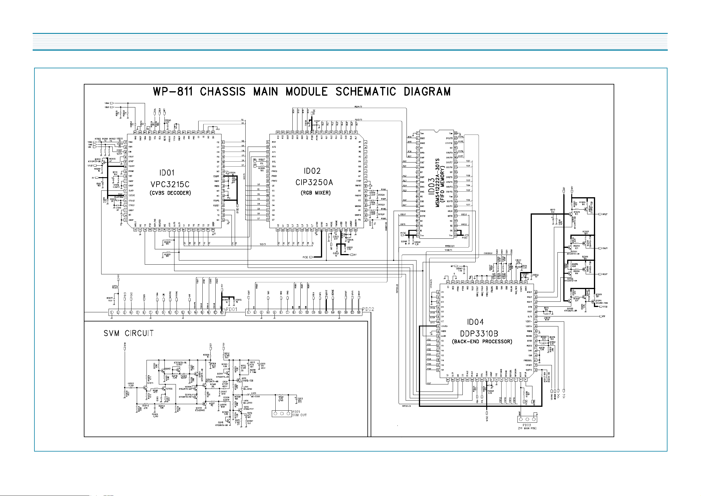
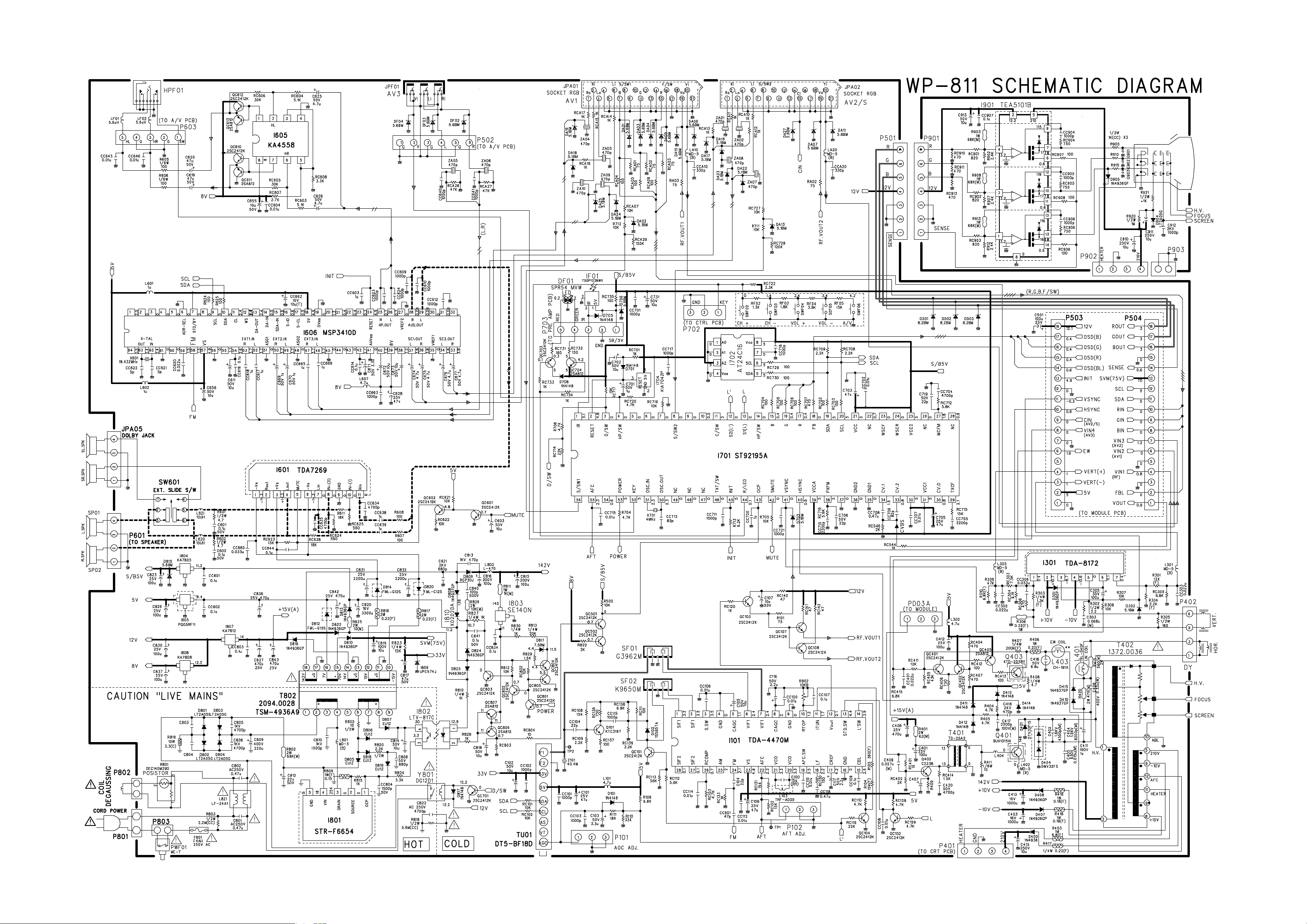
SCHEMATIC DIAGRAM
11
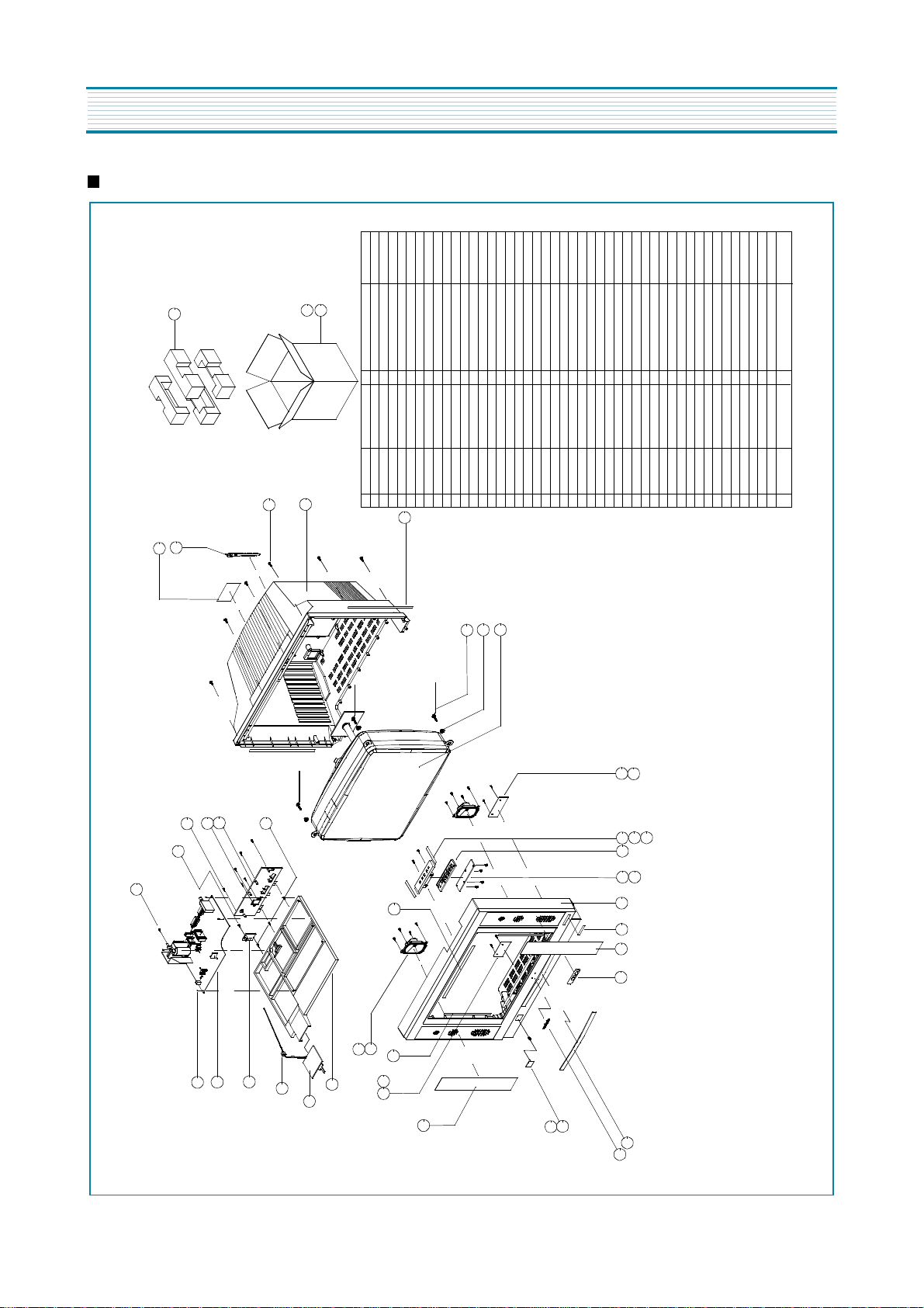
EXPLODED VIEW
DTW-28W2F
46
45
44
MATERIAL
FELT 400X20X0.7 4 CLOTH BLACK
TT2 TRS 4X14 MFZN BK 1 SCREW TAPPTITE
TT2 TRS 4X16 MFZN BK 1 SCREW TAPPTITE
TT2 WAS 3X12 MFZN BK 2 SCREW TAPPTITE
EPS 28W3 1
PE FOAM t0.5X1600X1270 1
DW-3 1
8 TT2 TRS 4X16 MFZN BK
W66ECK001X44
150ART P/E FILM (C/TV) 1
NYLON 66 BLK 5280N 1
SWRM+SK5 L=35 4
CR T2.0 4
FR HIPS GY (778A) 1
4 TT2 TRS 4X16 MFZN BK
FR HIPS BK 1 B/POWER PCB
NYLON66 UL/CSA 1 HOLDER AC CORD
TT2 TRS 4X14 MFZN BK 3
WP-811 1
FR HIPS BK 1
1 FR HIPS GY (778A) HOLDER CORD
TT2 TRS 4X16 MFZN BK
PVC T0.5 1
PC GY 1
SILVER DIA-CUTTING 1
SWPA PIE0.5 1
ABS GY (503A) 1
8 9 2
TT2 WAS 3X12 MFZN BK 4 7 ABS BK 1
HIPS GY (503A) 1
1
2 CLOTH 60X10X0.5 CLOTH BLACK
1
1
HIPS GY 1
FELT 180X10X1.5 2
HIPS GY (503A)
FELT 415X10X1.5 2
A1050P-H24 1
PS T0.5 28W2(L)
PS T0.5 28W2(R) 1
1
QTY
SCREW TAPPTITE
CLAMP CORD
PAD
BAG P.E.
BOX CARTON
7172401612
4858180700
4858215600
485805085K
46
45
44
2
43
43
CRT
SPEC PLATE
SCREW CRT FIX
WASHER RUBBER
4857817630
4859630260
4855415800
97P4602700
4856015820
4856215402
42
41
40
39
38
37
SCREW TAPPTITE
SCREW TAPPTITE
SCREW TAPPTITE 4 TT2 WAS 3X12 MFZN BK
PCB MAIN
TERMINAL ANT
7172401412
7172401612
7178301212
7172401612
36
35
34
33
97P2316600
7178301212
7172401412
4853529903
4853631102
4859803193
32
31
30
29
28
27
SPRING
SCREW TAPPTITE
SCREW TAPPTITE 2 TT2 WAS 3X12 MFZN BK
BUTTON POWER
MARK BRAND
SPEAKER
DECO AV
DECO SENSOR
FRAME MAIN PCB
4853817500
4855540600
48556174SD
4855933601
26
25
24
23
22
PREAMP PCB
7178301212
7172401612
4854856002
4856716000
18
21 1 20
19
17
16
SCREW TAPPTITE 2 TT2 TRS 4X16 MFZN BK
SCREW TAPPTITE 2 TT2 WAS 3X12 MFZN BK
SCREW TAPPTITE
AV JACK PCB
7178301212
7178301212
15
14
13
CLOTH BLACK
CLOTH BLACK
CTRL PCB
BUTTON
4854944601
12
11
DECO MARK
PANEL CTRL
4857818500
7172401612
4857821103
4857821101
4855930700
4852326302
8
6
5 1 4
10
PART NAME REMARKS
GRILL SPKR R/L
GRILL SPKR R/L
MASK FRONT
COVER BACK
4852534201
4852073102
4852155102
4852534200
PART CODE
3
2
1
NO
40
41
42
37
38
39
14
15
32
33
34
35
36
31
9
8
10
11
13
12
6
1
5
4
24
18
19
7
30
27
25
28
29
26
17
16
3
21
20
23
22
13
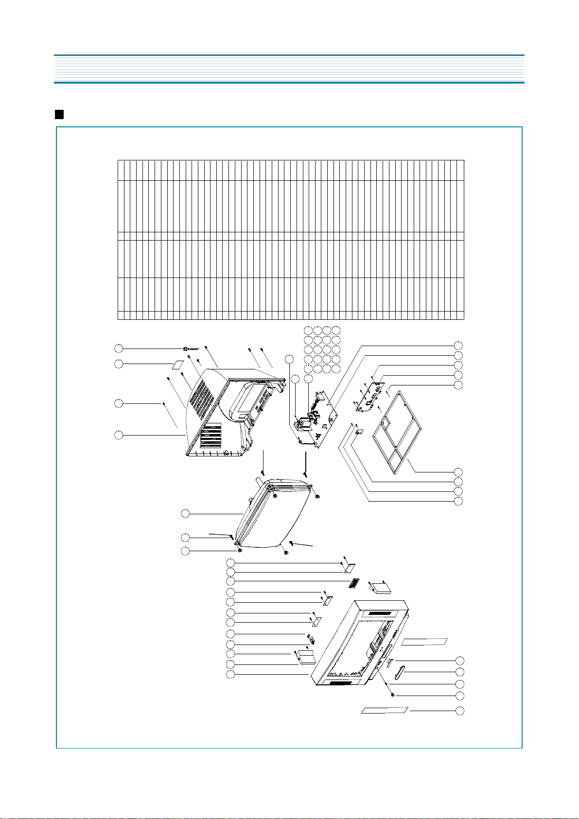
EXPLODED VIEW
DTW-2810F
1+8
1+52
28+52
24+28
26+52
24+26
23+24
23+52
1+15
1+10+11
1+6
1+4
1+2
Button
Switch
A/V Jack
PRE-AMP
TT2 TRS 4X16 MFZN BK SCREW TAPPTITE
NYLON 66 BLK 5280N
150ART P/E FILM(C/TV)
FR HIPS GY
1 NYLON 66 UL/CSA 97P2316600 HOLDER AC CORD
1
1 97P4602700
8
SPEC PLATE
CLAMP CORD
COVER BACK
4855415800
7172401612 1 4852154602
55
56
52
53
54
TT2 RND 3X10 MFZN 1
TT2 RND 3X10 MFZN
TT2 RND 3X8 MFZN
AL EX
1
1
HEAT SINK
SCREW TAPPTITE
4857027800
7174300811
50
51
TT2 RND 3X10 MFZN
AL EX
1 AL EX
1 AL EX
1
1
SCREW TAPPTITE
7174301011
49
1
SCREW TAPPTITE
HEAT SINK
HEAT SINK
HEAT SINK
SCREW TAPPTITE
4857026900
7174301011
4857026900
4857026900
7174301011
48
46
47
44
45
TT2 RND 3X8 MFZN 1 AL EX
AL EX BK
TT2 RND 3X8 MFZN
1
1 TT2 RND 3X8 MFZN
1
1
1 AL050P-H24 T=2
SCREW TAPPTITE
SCREW TAPPTITE
HEAT SINK
HEAT SINK
SCREW TAPPTITE
HEAT SINK
7174300811
4857025403
4857028205
7174300811
7174300811
43
4857031000
40
39
38
41
42
TT2 RND 3X8 MFZN
AL EXBK
PFC5000-0702
1
1 TT2 RND 3X8 MFZN
1 AL EX
1 TT2 RND 3X8 MFZN
SCREW TAPPTITE
7174300811
37
1 4857027534
1 AL EX
HEAT SINK
4857027910
36
2
HEAT SINK
SCREW TAPPTITE
SCREW TAPPTITE
HEAT SINK
CLIP FUSE
7174300811
4857027710
7174300811
4857415001
35
34
33
32
31
FR HIPS GY 1
T2S WAS 3X10 MFZN 4
WP-811
TT2 TRS 4X12 MFZNCK
1 T2S WAS 3X10 MFZN
1
5
TERM ANT
SCREW TAPPTITE
SCREW TAPPTITE
CHASSIS
SCREW TAPPTITE
7172401212
4853631002
7128301011
7128301011
26
27
30
29
28
52
TT2 TRS 4X12 MFZNCK
PC GY 1
PS SHEET T=0.4
SWPA PIE 0.5
HIPS GY
PHILIPS 28"WIDE
TT2 TRS 4X12 MFZNCK
SILVER DIA-CUTTING
FR HIPS BK
2 TT2 TRS 4X12 MFZNCK
SCREW TAPPTITE
7172401212
25
40 44 48
36
32 31
1
1
1 FR HIPS GY(778A)
1
1
HOLDER CORD
DECO SENSOR
SCREW TAPPTITE
FRAME M/PCB
MARK BRAND
SCREW TAPPTITE
7172401212
7172401212
4855526502
4853529903
4853817400
48556174SD
24
41 45 49
19
23
22
21
20
51
50
47
46
43
42 38 34
39
35
33 37
SWRM+SK5 L=35
1 4856716000
2
1
4
1
BUTTON POWER
GRILL
SCREW CRT FIX
CRT
SPRING
4854857903
4852530501
4856015820
15
16
18
17
14
30
53 56 55 54
CR T2.0
4
WASHER RUBBER
4856215402
13
T2S WAS 3X10 MFZN
HIPS GY 1
1
2
BUTTON
SUB-PCB
SCREW TAPPTITE
7128301011
4854929903
12
11
10
T2S WAS 3X10 MFZN
T2S WAS 3X10 MFZN 7128301011
T2S WAS 3X10 MFZN
2
1
2
1
2
SCREW TAPPTITE
SCREW TAPPTITE
SCREW TAPPTITE
SUB-PCB
SUB-PCB
48527160:9570151 : 9570151
7128301011
7128301011
9 8 7 6 5 4 3
2
1 HIPS GY
4 SWRM + SECC
1
SPKR SYSTEM
SCREW SPKR FIX
SUB-PCB
MASK FRONT
4856013600
4852072703
26
24 25 28 29 27
22 23
21
15 14 13
12 11
10
9
8
7
6
5
4
3
2
1
20
19 16
18
17
14
 Loading...