

Page 1

1. DESCRIPTION OF THE MECHANISM ....................................................2
2. ASSEMBLY DIAGRAM AND MAJOR PARTS CHECK.........................4
3. DIASSEMBLY AND REPLACEMENT .....................................................10
4. MECHANICAL ADJUSTMENT .................................................................16
5. ADJUSTMENT OF THE TAPE TRANSPORTING SYSTEM.................19
6. EXPLODED VIEW........................................................................................25
7. PARTS LIST....................................................................................................29
CONTENTS
T5 - DECK MECHANISM
(For EUROPE)
✔
Caution
: In this Manual, some parts can be changed for improving, their
performance without notice in the parts list. So, if you need the
latest parts information,please refer to PPL(Parts Price List) in
Service Information Center (http://svc.dwe.co.kr).
Page 2

2
1) T5-MECHA follows the VHS and the NTSC standard.
2) T5-MECHA uses 3 MOTORS (DRUM MOTOR, CAPSTAN MOTOR, L/C MOTOR).
3) T5-MECHA uses L/C Motor to drive FRONT LOADING.
4) T5-MECHA uses 4-BIT MODE signal to recognize each MODE.
This 4-BIT MODE signal is generated from the cam switch driven by the L/C MOTOR.
5) T5-MECHA has 7MODES (EJECT/INITIAL/REV/IDLE/PLAY,STOP,SLOW/BRAKE/FF&REW) operation.
6) T5-MECHA deduce the MODE changing time by adopting the full loading system which maintains the
tape winding the drum circumference.
7) T5-MECHA can be separated from the main pcb, and be assembled with B-B type connector . This B-B type
connectioning means that CAPSTAN MOTOR, LC MOTOR, AC HEAD, FE HEAD, DRUM are connected
directly without using connector cable.
1. DESCRIPTION OF THE MECHANISM
1-1 Characteristic of T5-DECK MECHANISM
Page 3
3
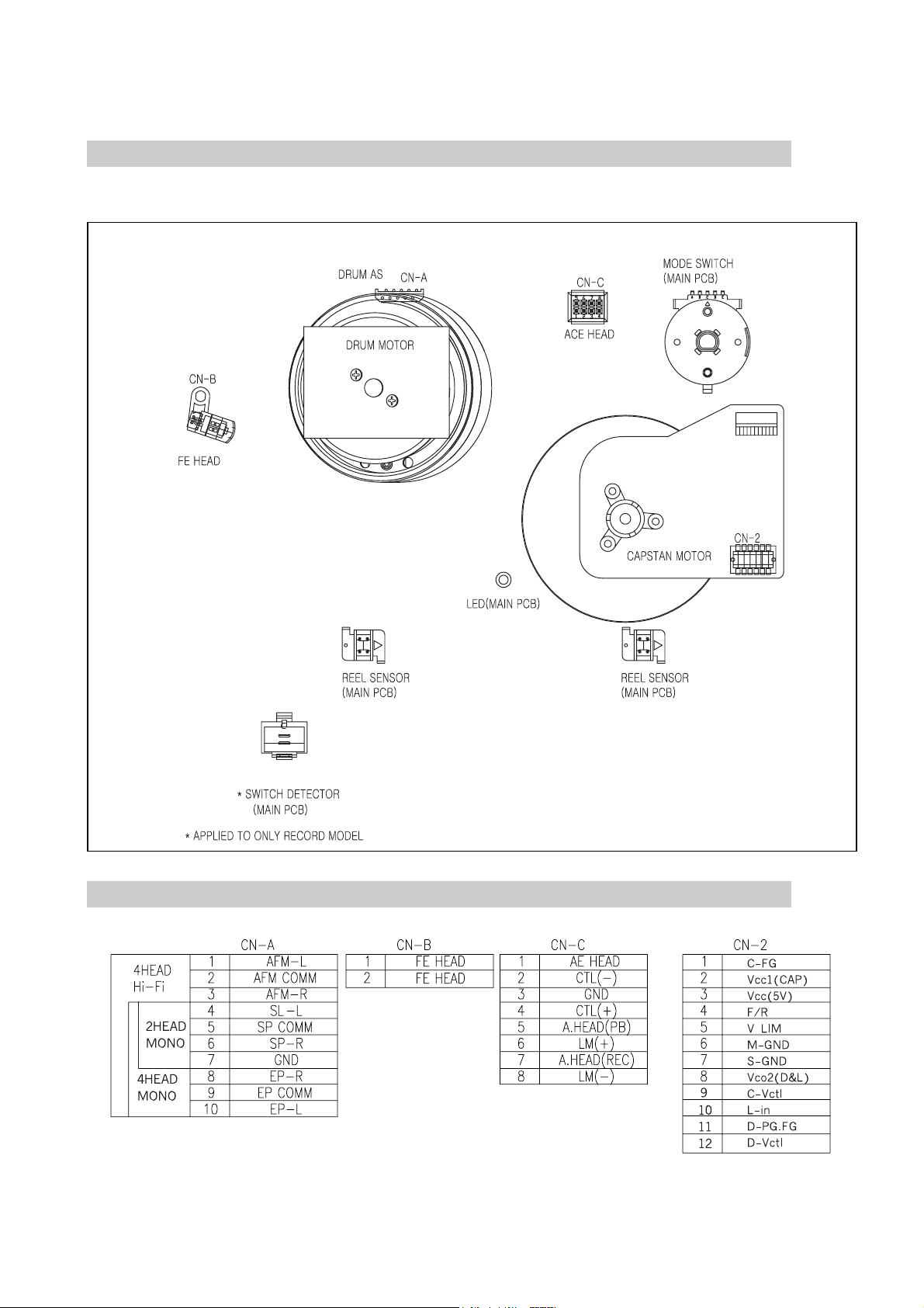
1-2 Wire Diagram
1-3 Connector Pin Arrangement
Page 4
2-1 Assembly Diagram
44
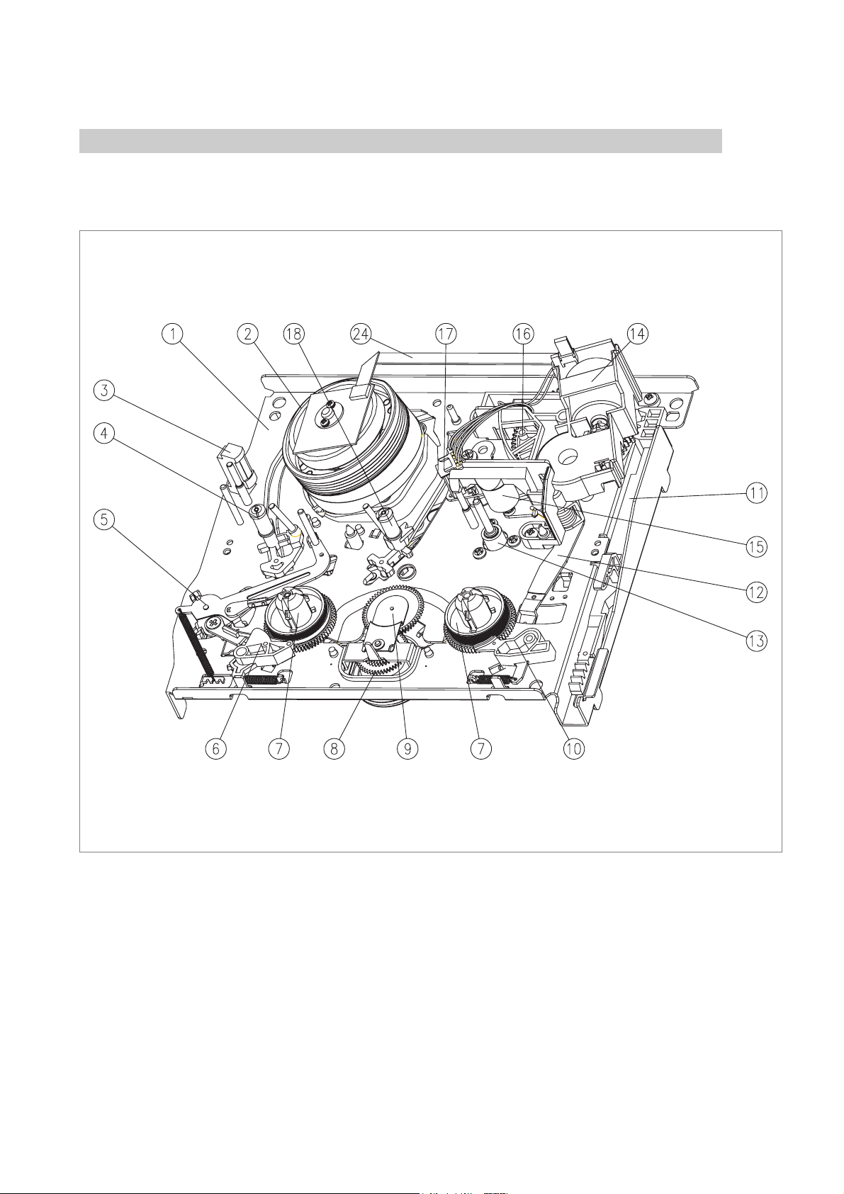
2-1-1) DECK Assembly Diagram
A. UPPER VIEW
2. ASSEMBLY DIAGRAM AND MAJOR PARTS CHECK
1 MAINBASE ASS’Y
2 DRUM ASS’Y
3 FE HEAD
4 S SLANT POLE ASS’Y
5 TENSION BAND ASS’Y
6 S BRAKE ASS’Y
7 REEL TABLE
8 REEL BRKT TOTAL ASS’Y
9 IDLER PLATE TOTAL ASS’Y
10 T BRAKE ASS’Y
11 FL RACK
12 RELAY LEVER
13 CAPSTAN MOTOR
14 LC BRKT ASS’Y
15 PINCH LEVER TOTAL ASS’Y
16 CAM GEAR
17 AC HEAD ASS’Y
18 T SLANT POLE ASS’Y
24 CABLE FFC
Page 5

5
B. BOTTOM VIEW
19 LOADING RACK
20 L LOADING ASS’Y
21 R LOADING ASS’Y
22 CONNECT PLATE
23 REEL BELT
24 CABLE FFC
Page 6
6
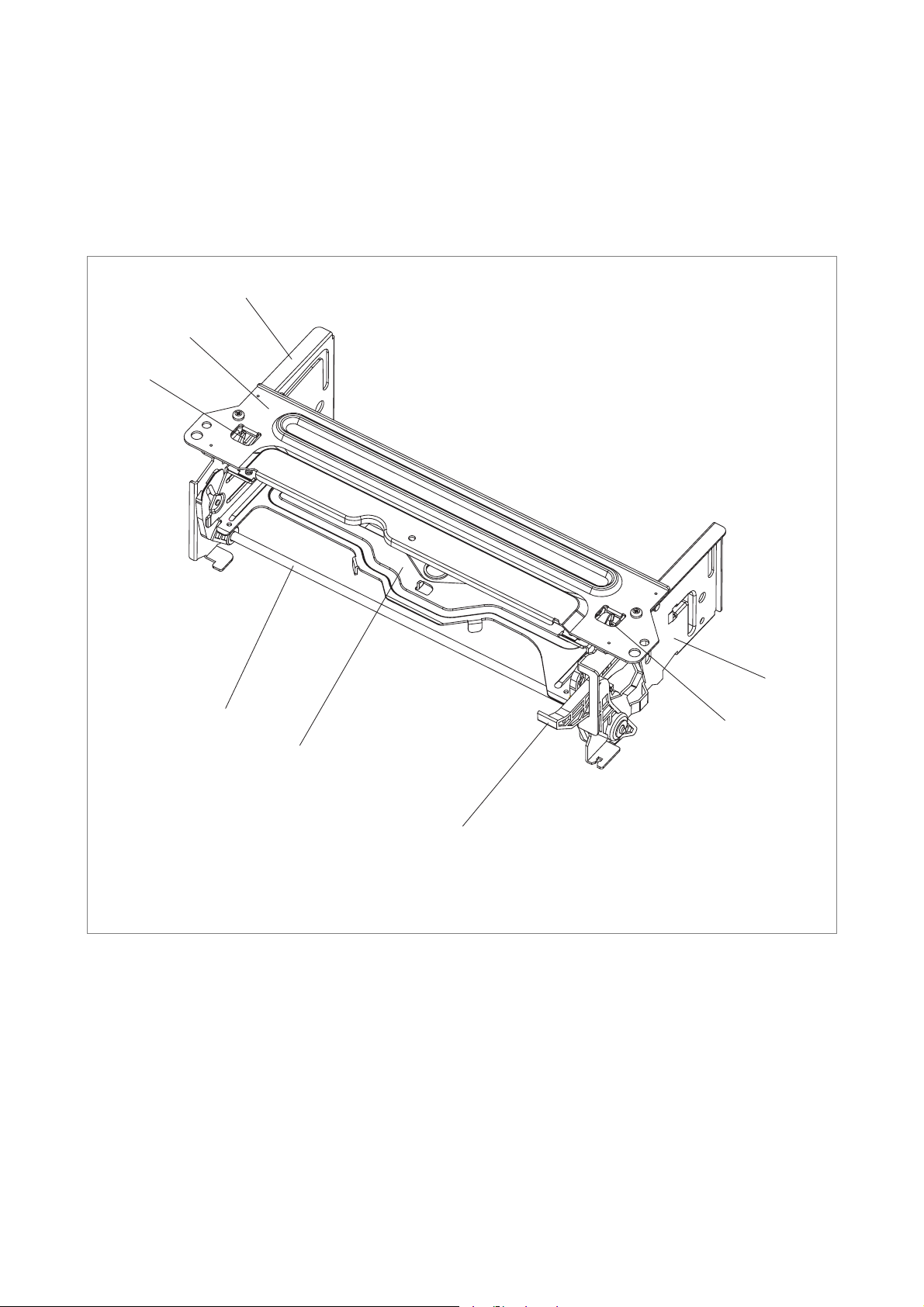
2-1-2) FRONT LOADING Assembly Diagram
!
@
#
$
%
^
&
*
1 FL BRKT L
2 TOP PLATE
3 SAFETY LEVER L
4 LOADING LEVER AS
5 CST HOLDER AS
6 DOOR OPENER
7 SAFETY LEVER R
8 FL BRKT R
Page 7
7
2-2-1) Periodic Maintenance and Service
Schedule
A. In order to effectively maintain the excellent performance
and fully utilize the features of this apperatus and to
lengthen the life of mechanism and tapes, we strongly
urge you to perform the periodic maintenance and
inspection as described below.
• Following should be done after the substition of parts of
deck or correction of deck failure.
B. Cleaning of the DRUM TOTAL ASS`Y
- Slowly turnning DRUM TOTAL ASS`Y, wipe the drum
surface with clean cloth soaked in alchol. (Don’t connect
the power when turnning the UPPER DRUM)
- Don’t wipe the Head-Tip vertically with cleaning cloths.
C. Tape transporting section cleaning
- Clean the tape transporting section with clean cloth
soaked in alchol.
D. Driving section cleaning
- Clean the driving section with clean cloth soaked in
alchol.
E. Everyday inspection
- Perform the maintenance and inspection periodically
according to the number of use.
- Refer to the table 2.2.3.
2-2-2) Cleaning and Lubrication
A. Cleaning of Tape Transporting section and driving section
a. Cleaning of Tape Transporting section
- The following parts shoule be cleaned after every 500
hours of use.
• TENSION POLE • S SLANT POLE
• AC HEAD/AE HEAD • GUIDE POST
• VIDEOHEAD / DRUM • T GUIDE POST
• FE HEAD • T SLANT POLE
• CAPSTASN SHAFT • S GUIDE ROLLER
• T GUIDE ROLLER • PINCH ROLLER
- Because the above part contact with video tape, they
tend to be stained with dusts and foreign substances
which make the bad effect on the picture and sometimes lead to the tape damage.
- Be sure to check the remained alchol during cleaning
evaporated thoroughly before using a tape.
b. Cleaning of the driving section
• REEL TABLE
• CAPSTAN FLYWHEEL/PULLEY
• REEL PULLEY
B. Lubrication
• REEL GEAR POST : After the cleaning the parts with
alchol, lubricate them with one or twol drops of ool
• S/T REEL TABLE POST : After the cleaning the parts
with alchol, lubricate them with grease.
2-2 Periodic Maintenance and Service Schedule
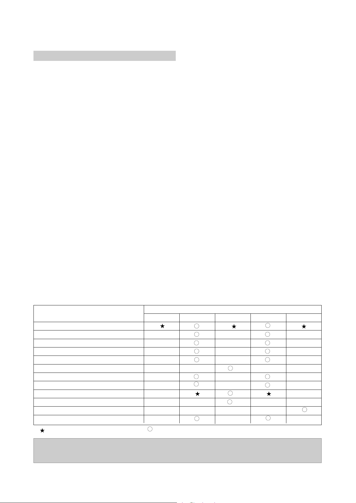
2-2-3) Service Sechedule for each parts
Following parts should be checked according to the recommanded intervals
: Check and replace if necessary. : Replace
Period Service (Hours)
PART Name 1000 2000 3000 4000 5000
DRUM TOTAL ASS’Y
CAPSTAN MOTOR
L/C BRKT TOTAL ASS’Y
REEL BELT
IDLER PLATE TOTAL ASS’Y
REEL TABLE
T BRAKE ASS’Y
TENSION BAND ASS’Y
PINCH ROLLER ASS’Y
AC HEAD ASS’Y
FE HEAD
REEL BRKT TOTAL ASS’Y
NOTE:
Independant of the above service shedule, Cleaning and lubrication and replacement of the
belt sould be undertaken every 2 years.
Page 8

8
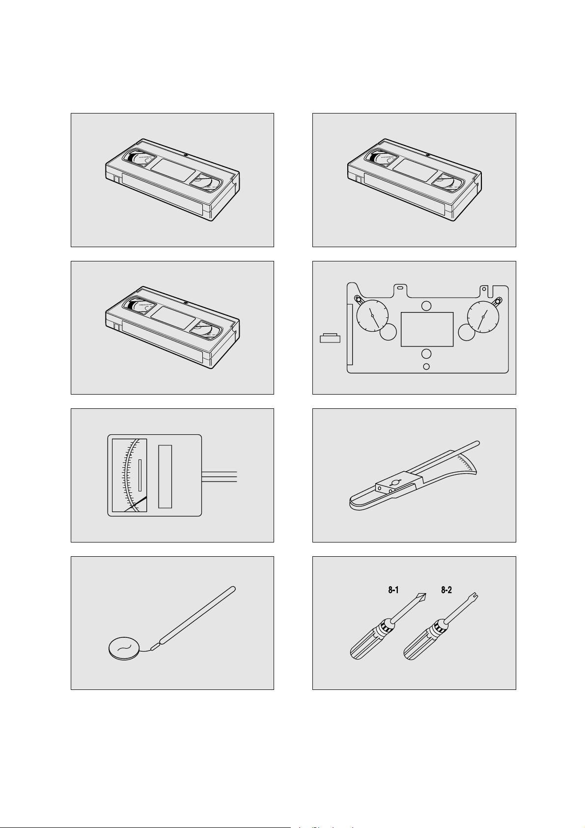
2-3-1) List of Jigs and Tools
FIG.
NO ITEMS MODEL
N O
REMARKS
NTSC: SP MONOSCOPE 7KHz CHECKING OF THE
1 ALIGNMENT T APE SP COLOR BAR 1KHz ! T APE TRANSPORTING
(EP MONOSCOPE) SECTION
2
CLEANING T APE
DHC-602V @
CHECKING OF THE T APE
(DAEWOO) TRANSPORTING SECTION
3
CASSETTE T APE TORQUE KT -300NV
#
MEASUREMENT OF THE
METER(KOKUSAI) KT-300R V REEL TORQUE
4
VHS SPINDLE
TSH-V4 $
MEASUREMENT OF
HEIGHT GAUGE REEL T ABLE HEIGHT
5
TENTELO METER
T2-H7-UM %
MEASUREMENT OF
(TENTELO) THE BACK TENSION
FAN TYPE MEASUREMENT OF THE
6 TENSION METER
<
3KG ^ PRESSING FORCE FOR
THE PINCH ROLLER
7 DENT AL MIRROR &
CHECKING OF THE T APE
TRANSPORTING SECTION
+
DRIVER *-1 ASSEMBLY,
8 DISASSEMBLY
ADJUSTMENT DR IVER *-2 AND ADJUSTMENT
2-3 Jig and Tools
Page 9
9
2-3-2) A Skectch of Jigs and Tools
!
#
%
&
@
$
^
*
ALIGNMENT TAPE
CLEANING TAPE
30
20
10
30
0
20
10
VHS SPINDLE
HEIGHT GAUGE
30
20
10
30
0
10
20
Page 10

10
a. Unscrew the 2 screw holding the F/L.
b. Separate the F/L ASS`Y from the MAIN BASE settling
down point by lifting the rear part of F/L(Screw hole).
a. Remove the one WASHER for holding the door opener
and separtate F/L Assembly by moving the DOOR
OPENER in the direction of arrow.
b. Remove the 2 screw holding the TOP PLATE and sepa-
rate the CASSETT HOLDER ASS`Y by moving the
FL BRKT L and FL BRKT R in the direction of arrow
(Fig. 3.2)
NOTE:
REMOVE THE FRONT LOADING ASS`Y IN EJECT
MODE
Fig. 3.1 Diassembly of the FRONT LOADING ASS`Y
Fig. 3.2 Diassembly of the FRONT LOADING ASS`Y
3. DISASSEMBLY AND REPLACEMENT
3-1 Removal of the FRONT LOADING ASS’Y
(Fig. 3.1)
3-2 Disassembly of FRONT LOADING ASS’Y
(FIg. 3.2~3.5)
Page 11

11
c. Separate the LOADING LEVER ASS`Y by pressing
the connection point from the CASSETTE HOLDER
ASS`Y.(Fig. 3.3)
d. Remove the SAFETY SPRING connecting the SAFETY
LEVER and CASSETTE HOLDER PLATE.(Fig. 3.3)
e. Remove the RELEASE SPRING connecting the
RELEASE LEVER and SAFETY LEVER.(Fig3.3)
a. Turn over the DECK MECHANISM and holding the
DRUM TOTAL ASS`Y @ with hands , remove the 3
screw holding the drum total assembly with main base.
b. Separatet the DRUM TOTAL ASS`Y from the deck pay-
ing attention there is no damage on the surface of VIDEO
HEAD and DRUM.
c. Assembly step is the reverse way of diassembly.
CAUTION:
Assemble the FRONT LOADING ASS`Y in the reverse
step of diassembly. Confirm that two bosses on the left
side of the CASSETTE HOLDER ASS`Y are inserted in
the groove on the left side of the top plate. Insert two
bosses on the right side of the CASSETTE HOLDER
ASS`Y into the groove of the F/L BRACKET R.(Fig. 3.4)
FIg. 3.3 Disassembly of the CASSETTE HOLDER Ass’y
FIg. 3.4 Assembly of the FL Ass’y
CAUTION:
• After the assembly of the DRUM TOTAL ASS`Y,
check out if DECK mecahnism operate smoothly and
adjustment of tape transmission section is OK.
FIg. 3.5 Diassembly of DRUM ASS`Y
3-3 Disassembly of DRUM ASS’Y (Fig. 3.5)
Page 12

12
a. Turn out the DECK MECHANISM and remove the
LOADING RACK @ after unscrewing the SCREW .
b. Disintegrate the R LOADING AS # and L LOADING
AS $ .
c. Disintegrate the S SLANT POLE AS % and T SLANT
POLE AS ^ by moving those part in arrow dircetion.
a. Remove the CONNECTOR @ from the AC HEAD
ASS`Y, Watch out that there is no damage in the HEAD
connecting PIN.
b. Separate the AC HEAD ASS`Y ! after unscrewing the-
screw #
CAUTION:
• Take care GUIDE ROLLER of S/T SLANT POLE AS
and SLANT POLE not to be stained with grease during
assembly.
• Refer to Fig. 3.7 in assembly.
FIg. 3.6 Disassembly of the LOADING RACK, LOADING
ASS’Y and the SLANT POLE ASS’Y
FIg. 3.7 Assembly of the L/R LOADING AS and the
LOADING RACK
CAUTION:
• After the assembly, adjust the tape transmissionsection by refering to the chapter 5.
• After the adjustment of the tape transmission section,
paint the 3 adjustment screw with locking paint.
FIg. 3.8 Disassembly of the AC HEAD ASS’Y
3-4 Disassembly of LOADING RACK, LOADING
ASS’Y, S/T SLANT POLE ASS’Y (Fig. 3.6, 3.7)
3-5 Disassembly of the A/C HEAD ASS’Y
(Fig. 3.8)
Page 13

13
a. Separate the LC BRKT Ass’y @ after removing the 3
screws !.
b. Separate the LC BRKT Ass’y @ from the DECK
MECHANISM.
c. Disintegrate the PINCH LEVER TOTAL Ass’y #.
a. Separate the CAM GEAR % from the MAINBASE.
b. Separate the RELAY LEVER ^ from the MAINBASE.
c. Separate the FL RACK & from MAINBASE by moving
to the arrow direction.
CAUTION:
• After the assembly of the PINCH LEVER TOTAL
Ass’y, adjust the tape transmission section by refering to
the chapter 5.
• There should be no pollution on the surface of
PINCH ROLLER $ with grease or other foreign
material.
• Make sure if the end of the PINCH SPRINGPINCH
“A” is located at the end of trajectory of CAM GEAR
“B” in assembly (Refer to Fig. 4.3)
CAUTION:
• When reassembling, refer to Fig. 3.10, Fig. 3.11 and
chapter 4.
FIg. 3.9 Disassembly of the LC BRACKET ASS’Y from
the PINCH LEVER TOTAL ASS’Y
FIg. 3.10 Assembly of the CAM GEAR, RELAY LEVER
FIg. 3.11 Assembly of the CAM GEAR, FL RACK
3-6 Disassembly of the LC BRKT ASS’Y, PINCH
LEVER TOTAL ASS’Y (Fig. 3.9)
3-7 Disassembly of the CAM GEAR, RELAY
LEVER, FL RACK (Fig. 3.9)
Page 14

14
a. Unhook the S BRAKE SPRING # from the MAIN-
BASE HOOK !.
b. Remove the S BRAKE Ass’y @ from the mainbase.
c. Remove the T BRAKE SPRING ^ from the MAIN-
BASE HOOK $.
d. Remove the T BRAKE Ass’y %.
a. Unhook the TENSION SPRING @ from the MAIN-
BASE HOOK !.
b. Unhook the MAINBASE HOOK “A” and remove the
TENSION BAND Ass’y # from the mainbase.
a. Separate the CAPSTAN MOTOR % after the removal of
3 screws $ holding the capstan motor.
a. Remove the screw ^ and separate the FE HEAD & from
the MAINBASE.
CAUTION:
• After the assembly of TENSION BAND Ass’y on the
mainbase, adjust the TENSION POLE location as
shown in Fig. 3.14.
• Avoid getting Grease, Oil or Foreign substance on the
FELT of the BAND BRAKE.
• Take care not to deform the MAINBASE HOOK “A”
when separating the TENSION BAND Ass’y #.
FIg. 3.12 Disassembly of the S/T BRAKE ASS’Y
FIg. 3.13 Disassembly of the TENSION BAND ASS’Y,
CAPSTAN MOTOR and the FE HEAD
FIg. 3.14 Adjustment of the TENSION POLE POSITION
3-8 Disassembly of the S/T BRAKE ASS’Y
(Fig. 3.12)
3-9 Disassembly of the TENSION BAND ASS’Y
(Fig. 3.13)
3-10 Disassembly of the Capstan Motor
(Fig. 3.13)
3-11 Disassembly of the FE HEAD (Fig. 3.13)
Page 15

15
a. Remove the POLY WASHER ! and separate the
IDLER PLATE TOTAL Ass’y @ from the mainbase.
b. Remove the REEL TABLE $ from the REEL TABLE
POST # of the MAINBASE.
a. Turn over the DECK MECHANISM and remove 2
screws !.
b. Remove the REEL BRKT TOTAL Ass’y @ from the
MAINBASE.
c. Separate the CONNECT PLATE # from the MAIN-
BASE by pushing to the direction of the arrow.
CAUTION:
• Take care not to deform the IDLER PLATE TOTAL
Ass’y @ when assembling and disassembling.
CAUTION:
• In diassembly of the REEL BRKT TOTAL ASS`Y,
take care REEL BELT and REEL FELT not to be
stained with GREASE, OIL, or foreign substance.
• diassembly of the IDLER ASS`Y should be precede
the diassembly of the REEL BRKT TOTAL ASSY.
• Check the operation of the REEL BRKT TOTAL
ASSY before assembly.
• Check the operation of FF/REW, PLAY, CUE, and
REVIEW work well and existence of noise during
the mode operation..
FIg. 3.15 Disassembly of the REEL TABLE and the IDLER
PLATE TOTAL ASS’Y
FIg. 3.16 Disassembly of the REEL BRKT TOTAL ASS’Y
and the CONNECT PLATE
3-12 Disassembly of the REEL TABLE, IDLER
PLATE TOTAL ASS’Y (Fig. 3.15)
3-13 Disassembly of the REEL BRKT TOTAL
ASS’Y, CONNECT PLATE (Fig. 3.16)
Page 16

16
4. MECHANICAL ADJUSTMENT
In case of diassembly and reassembly for fixng the mecanical
problem, check the following check point.
a. Make sure that the DATUM HOLE of the CAM GEAR is
aligned wth the DATUM HOLE in the MAINBASE in
the EJECT modew as shown in Fig. 4-1.
b. Make sure that the ending part “A” of the RELAY
LEVER assembled on the CONNECT PLATE is aligned
with the reference hole “B” of the MAINBASE as shown
in Fig. 4.2.
c. The end point “A” of PINCH SPRINGPING of the
LEVER TOTAL ASS`Y should be located within the
trajectory “B” of the CAM GEAR. (Fig. 4.3)
FIg. 4.1 Assembly reference between the FL RACK and the
CAM GEAR
TURN TO THE END
ALIGN
FIg. 4.2 Assembly reference between the RELAY LEVER
and the CAM GEAR
FIg. 4.3 Assembly reference of the PINCH LEVER TOTAL
ASS’Ywith the CAM GEAR
4-1 Mechanical Adjustment (Fig. 4.1~4.4)
Page 17

17
d. Make sure that the triangular mark “A” of the L LOAD-
ING Ass’y is aligned with the mark “b” of the R LOADING Ass’y. (Fig. 4.4)
e. Reference hole “C” of the LOADING RACK should be
aligned with the reference hole of the R LOADING Ass’y
to make the teeth of the LOADING RACK is aligned as
shown in Fig. 4.4.
a. Check that the location of the TENSION POLE is in the
right position. if not, adjust that by refering to the “4.4
Adjustment of the TENSION POLE position”.
b. Play back the T-120 TAPE in S-MAX for 20
seconds.(Generally tape transporting section is settled
down in 20 seconds)
c. Measure the BACK TENSION by using the TENTELO
METER (Refer Fig 4.5) The result should be within the
range of 20g ~ 30g.
d. If the BACK TENSION is out of the range, change the
position of the TENSION SPRING of repeat the
process of “4.4 Adjustment of the TENSION POLE
position”.(Fig. 4.6)
FIg. 4.4 Assembly reference between the LOADING RACK
and the LOADING LEVER ASS’Y
CAUTION:
• If the measurement result greater than the upper limit,
change the hook point of the spring to position “A”
• Confirm that all of the three probes of TENTELO
METER are in contect with the tape.
• During measuring, don`t touch any other parts of the
MECHANISM(i.e. MAINBASE). It is recommendedthat this measurment be repeated at least three
times for an accurate reading.
FIg. 4.5 Measurement of the BACK TENSION
4-2 Adjustment and Measurement of the BACK
TENSION (Fig. 4.5, 4.6)
Page 18

18
a. Remove the FRONT LOADING MECHANISM from the
DECK MECHANISM
b. Cap the IR LED and pull the FL RACK. This has the same
effect with cassette loading to the deck.
c. If the S,T POLE BASE is loaded, PLAY MODE starts
automatically. If you want other function, press the corresponding button.
d. Turn off the poser when the Mechanism is in the desired
position.
a. Place the MECHANICAL MODE in the PLAY MODE.
Refer to the above section “4.3 MECHANICAL MODE”
b. Confirm that the TENSION LEVER is aligned with the
datum hole of the MAINBASE.
c. If the requirement “b” is not satisfied. turn the BAND
BRAKE ADJUST CAP clockwise or counterclockwise
until the two datum holes aligns with each other.
FIg. 4.6 Adjustment of the TENSION POLE POSITION
4-3 Mechanical Mode (Operate without a
Cassette Tape)
4-4 Adjustment of the position of the TENSION
POLE (Fig. 4.6)
Page 19

19
5. ADJUSTMENT OF THE TAPE TRANSPORT SECTION.
Generally, tape transporting section has been precisely adjusted in the factory and does not require the ordinary readjustment.
But there is the case that tape noise or impact on the deck mechanism, tape transporting section readjustment is required. In
adjustment of the tape transmission section refer to the following flow chart.
If any components shown in Fig. 5.1 are changed, readjustment of the tape transporting section is needed.
FIg.5.1 A schematic diagram of the tape transport ing section.
Page 20

20
S/T GUIDE ROLLER HEIGHT
ADJUSTMENT
•DRUM TOTAL AS
•A/C HEAD AS
•PINCH LEVER TOTAL
AS
S/T GUIDE ROLLER FLUNGE
A/C HEAD AS ADJUSTMENT (TILT ADJUSTMENT)
CLEANING
AUDIO AZIMUTH ADJUSTMENT
A/C HEAD ADJUSTMENT
X-POSITION ADJUSTMENT
PLAYBACK PHASE ADJUSTMENT
LINEARITY ADJUSTMENT
DRUM ENTRANCE/EXIT ENVELOPE FINE TUNING
REVIEW PLAY CHANGING OPERATION CHECK
AUDIO AZIMUTH ADJUSTMENT
AUDIO OUTPUT CHECK (A/C HEAD HEIGHT& TILT ADJUSTMENT)
X-POSITION ADJUSTMENT
TRACKING
•S SLANT PLOE AS
•T SLANT POLE AS
•TENSION BAND AS
Table.1 Adjustment Flow Chart of the Tape Transporting System
Page 21

21
A. Adjustment of the S/T GUIDE ROLLER
A. Adjustment of the S/T GUIDE ROLLER
a. Check the Playing back with a T-120 TAPE.
b. Make sure that excessive tape wrinkle does not occure
ateatch S, T GUIDE ROLLER.
c. If tape wrinkle is observed at the S/T GUIDE ROLLER,
turn the guide roller screw until there is not tape wrinkle.
B.Adjustment of the AC HEAD ASS’Y(TIL T)
a. Play back a T-120 TAPE and check the running status of
lower side of GUIDE POST.
b. If there is any problem, Turn the AC HEAD TILT
SCREW until the running status improved. (Fig. 5.2)
C.Adjustment of the AC HEAD Height(Fig. 5.3)
a. Paly back a T-120 TAPE..
b. Make sure that the gap between the lower end of TAPE
and the AC head is 0.25m.
c. If the measurement of the gap is different from the refer-
ence value 0.25mm, turn the screw ! , # until the
desired gap is obtained.
D.Adjustment of the AUDIO AZIMUTH(Fig. 5.4)
a. Play back the ALIGNMENT TAPE
(DN2 : SP, NTSC,7KHz)
b. Check the AUDIO output with a AUDIO LEVEL
METER.
c. Turn the AC HEAD AZIMUTH SCREW @ until the
maximum AUDIO output(-9dBm ~ -3dBm)is obtained.
E.Adjustment of the X-POSITION(Fig. 5.4 5.5)
a. Connect the PATH ADJ. FIXTURE to the PT01 on the
MAIN CIRCUIT BOARD.
b. Play back the ALIGNMENT TAPE (DN2 : SP MONO-
SCOPE).
c. Connect the S/W pin and ENVE pin of the PATH ADJ.
FIXTURE with the SCOPE PROBE.
d. Insert the adjustment bar in the AC HEAD ADJUST hole
$ and adjust the X-POSITION of the AC HEAD
ASS`Y until the ENVE is maximum when the VR is on
the CENTER.
• Three is the possibility that an another TRACKING CENTER can be occur when the AC HEAD ASS`Y turned
completely in the counterclockwise direction, Hence adjust
the X-position with AC HEAD ASS’Y adhering closely
to the right side until the maximum ENVE is obtained.
e. The adjustment of the X-POSITION finished, check
if the AUDIO LEVEL is degraded, then readjustment
of the AUDIO AZIMUTH is required.
FIg.5.2 Adjustment of the AC HEAD ASS’Y
FIg.5.3 Adjustment of AC HEAD Height
FIg.5.4 Adjustment of AUDIO AZIMUTH, X-POSITION
S/W PULSE TEST PIN PATH ADJ. FIXTURE
ENVELOPE TEST PIN PATH ADJ.FIXTURE
Measurement Equipment OSILLOSCOPE
VR CONTROL PATH ADJ.FIXTURE
AC HEAD ADJUST HOLE ADJUSTMENT BAR
Test Point
Adjustment
Page 22

F. PLAYBACK PHASE Adjustment(Fig. 5.6)
PHASE GENERATOR(PG) SHIFTER determine the
VIDEO HEAD SWITCHING POINT when the TAPE is
played back. If an adjustment of the PHASE GENERATOR(PG) SHIFTER is not done precisely, There can be a
HEAD SWITCHING NOISE or a VERTICAL JITTER
problem, vibration of the picture on the screen, not good
quality of picture in special play back.
a. Connect the PT01 on the MAIN CIRCUIT BOARD with
a PATH ADJ. FIXTURE.
b.
Play back an ALIGNMENT TAPE(DN-2 : MON-SCOPE signal)
c. Connect the S/W PULSE TEST PIN on the PATH ADJ.
FIXTURE with a CHANNEL-1 SCOPE PROBE.
d. Connect the VIDEO OUT on the MAIN CIRCUIT
BOARD with a CHANNEL-2 SCOPE PROBE (1V/div).
e. Control the PG VOLUME until the time interval
between the SWITCHING PULSE and the V-SYNC
SIGNAL is within the 6.5H±0.5H as shown in Fig. 5.6.
G.Adjustment of the LINEARITY(Fig. 5.7)
a. Connect the PT01 on the MAIN CIRCUIT BOARD with
a PATH ADJ. FIXTURE.
b. Play back an ALIGNMENT TAPE(DN-2 : MONO-
SCOPE Signal).
c. Connect the FIXTURE S/W PULSE TEST PIN on the
PATH ADJ. CHANNEL-1 SCOPE PROBE.
d. Connect the VIDEO OUT on the MAIN CIRCUIT
BOARD with a CHANNEL-2 SCOPE PROBE (1V/div).
e. Adjust the VR CONTROL on the ADJ. FIXTURE until
the ENVELOPE signal is maximum while play back the
ALIGNMENET TAPE.
f. Adjust the S/T GUIDE ROLLER until the envelope signal
waveforms of the entrance and exit sides are as shown in
Fig. 5-7.
22
FIg.5.5 Adjustment of the X-POSITION
S/W PULSE TEST PIN PATH ADJ. FIXTURE
ENVELOPE TEST PIN PATH ADJ.FIXTURE
Measurement Equipment OSILLOSCOPE
VR CONTROL PATH ADJ.FIXTURE
S/T GUIDE ROLLER TAPE TRANSPORT SECTION
Test Point
Adjustment
a: Max Output of Envelope
b: Min Output of Envelope
FIg.5.7 Adjustment of Linearity
Fig.5.6 Playback Phase Adjustment
S/W PULSE TEST PIN MAIN CIRCUTE BOARD
ENVELOPE TEST PIN MAIN CIRCUTE BOARD
Measurement Equipment OSILLOSCOPE
VR 595(PG SHIFTER) MAIN CIRCUTE BOARD
Test Point
Adjustment
Page 23

23
H. Adjustment of the Wave Form of DRUM
Entrance / Exit (Fig. 5.8)
a. Connect the PT01 on the MAIN CIRCUIT BOARD with
a PATH ADJ.FIXTURE.
b. Play back an ALIGNMENT TAPE(DN-2 : MONO-
SCOPE signal)
c. Connect the S/W PULSE TEST PIN on the PATH ADJ.
FIXTURE with a CHANNEL-1 SCOPE PROBE.
d. Connect the VIDEO OUT on the MAIN CIRCUIT
BOARD with a CHANNEL-2 SCOPE PROBE(1V/div).
e. Turn the VR CONTROL on the PATH ADJ.FIXTURE
clockwise or counterclockwise until the signal shape of
ENVELOPE has the constant thickness.(Fig.5.8)
f. Adjust the S/T GUIDE ROLLER if the thickness of the
ENVELOPE signal is not uniform.
I. REVIEW PLAY(Fig. 5.9)
a. Connect the PT01 on the MAIN CIRCUIT BOARD with
a PATH ADJ.FIXTURE.
b. Play back an ALIGNMENT TAPE(DN-2 : MONO-
SCOPE signal)
c. Connect the S/W PULSE TEST PIN on the PATH ADJ.
FIXTURE with a CHANNEL-1 SCOPE PROBE.
d. Connect the VIDEO OUT on the MAIN CIRCUIT-
BOARD with a CHANNEL-2 SCOPE PROBE (1V/div).
e. Make the VR CONTROL on the PATH ADJ. FIXTURE
to the center to maximize the ENVELOPE signal.
f. Play back the REVIEW mode about 15 second and alter
the mode to PLAY MODE.
g. Check whether the ENVELOPE waveform restore to its
original form within 3 second when the REVIEW mode is
changed to PLAY mode.
h. If the requirement of “g” is not satisfied, Check the run-
ning status of tape on the lower part of TGUIDE POST
and adjust the S/T GUIDE ROLLER precisely
.
J.Checking AUDIO Output Waveform (Adjustment
of AC HEAD TILT & Height)
a. Connect the AUDIO output jack with an AUDIO LEVEL
METER.
b. Playback an Alignment Tape (DN-1:Color Bar 1KHz
Signal)
c. Check if the AUDIO output signal level is over -9~-
3dBm.
d. If the requirement of “c” is not satisfied, readjust the AC
HEAD TILT and the HEIGHT until the AUDIO output is
maximized. (Fig. 5.2, 5.3)
S/W PULSE TEST PIN PATH ADJ. FIXTURE
ENVELOPE TEST PIN PATH ADJ.FIXTURE
Measurement Equipment OSILLOSCOPE
VR CONTROL PATH ADJ.FIXTURE
S/T GUIDE ROLLER TAPE TRANSPORT SECTION
Test Point
Adjustment
FIg.5.8 Fine adjustment of the ENVELOPE at the DRUM
ENTRANCE/EXIT
S/W PULSE TEST PIN PATH ADJ. FIXTURE
ENVELOPE TEST PIN PATH ADJ.FIXTURE
Measurement Equipment OSILLOSCOPE
VR CONTROL PATH ADJ.FIXTURE
S/T GUIDE ROLLER TAPE TRANSPORT SECTION
Test Point
Adjustment
FIg.5.9 Waveform change when the modealtered
(REVIEW ↔PLAY)
AUDIO OUTPUT AUDIO OUTPUT JACK
AUDIO LEVEL METER
Test Point
Measurement Equipment
Page 24

24
K.Adjustment of the AUDIO AZIMUTH
a. Connect the AUDIO output JACK with an AUDIO
LEVEL METER.
b. Play back the ALIGNMENT TAPE(DN-2:MONO-
SCOPE 7KHz Signal).
c. Check if the AUDIO output signal level is over : -9 ~-
3dBm.
d. If the requirement of “c” is not satisfied, readjust the
AZIMUTH SCREW of the AC HEAD until the AUDIO
output is maximum.(Fig. 5.4)
e. Repeat the process of “Adjustment of the Wave Form
of DRUM Entrance/Exit”
L.X-POSITION
a. Connect the PT01 on the MAIN CIRCUIT BOARD with
a PATH ADJ. FIXTURE.
b. Play back an ALIGNMENT TAPE(DN-2 : MONO-
SCOPE Signal).
c. Connect the S/W PULSE TEST PIN on the PATH ADJ.
FIXTURE with a CHANNEL-1 SCOPE PROBE.
d. Connect the VIDEO OUT on the MAIN CIRCUIT
BOARD with a CHANNEL-2 SCOPE PROBE (1V/div).
e. Check if the ENVELOPE is maximum when the VR
CONTROL on the PATH ADJ. FIXTURE is in CENTER
f. If the requirement “e” is not satisfied, readjust the X-POSI-
TION by referring to subitem “E”(Adjustment of the XPOSITION).
g. Repeat the process of subitem “F”(PLAYBACK PHASE
ADJUSTMENT).
AUDIO OUTPUT AUDIO OUTPUT JACK
AUDIO LEVEL METER
Test Point
Measurement Equipment
S/W PULSE TEST PIN PATH ADJ. FIXTURE
ENVELOPE TEST PIN PATH ADJ.FIXTURE
Measurement Equipment OSILLOSCOPE
VR CONTROL PATH ADJ.FIXTURE
S/T GUIDE ROLLER
TAPE TRANSMISSION T SECTION
Test Point
Adjustment
Page 25

25
6-1 Exploded View of DECK Ass’y ( Top View)
6. EXPLODED VIEW
Page 26

26
6-2 Exploded View of DECK Ass’y ( Bottom View)
Page 27

27
6-3 Exploded View of FL Ass’y
Page 28

28
D0040
D0040
D0020
D0050
D0010
D0060
D0070
6-4 Exploded View of DRUM Ass’y
Page 29

29
7. PARTS LIST
LOC. PARTS CODE PARTS NAME PARTS DESCRIPTION
NTSC
M1000 PVDKARNB41 VCR DECK AS(T50) DRN-B401 (4HD, SP/LP, NON-DLC, AHC)
PVDKARNB60 VCR DECK AS(T50) DRN-B600 (6HD, HI-FI, NON-DLC)
PAL
M1000 PVDKARPB20 VCR DECK AS(T50) DRP-B200 (2HD, SP/LP, NON-DLC)
PVDKARPB60 VCR DECK AS(T50) DRP-B600 (6HD, HI-FI, NON-DLC)
SECAM
M1000 PVDKARPB20 VCR DECK AS(T50) DRP-B200 (2HD, SP/LP, NON-DLC)
PVDKARSB60 VCR DECK AS(T50) DRS-B600 (6HD, HI-FI, NON-DLC)
LOC. PARTS CODE PARTS NAME PARTS DESCRIPTION
DRUM ASS’Y
D0010 DRUM AS (REFERRING TO LIST OF DRUM PRICE)
D0020 97SA329500 DRUM M/T AS DMVDMT07F
97SA329800 DRUM M/T AS I20AL-05G2
D0040 7001260711 SCREW MACHINE PAN 2.6X7 MFZN
D0050 97SA320400 EARTH GROUND AS T-DRUM
D0060 97S2303600 HOLDER MAIN POM(KEPITAL F20)
D0070 97S2303800 HOLDER CAP(B) POM(4CH)
D0070 97S2303900 HOLDER CAP(C) POM(6CH) DECK ASS’Y
DECK ASS’Y
AM001 DECK AS (REFERRING TO LIST OF DECK TOTAL ASS’Y)
A0100 97SA332200 MAIN BASE AS T4.5-MECHA
A0200 97SA316500 S SLANT POLE AS T-MECHA
A0300 97SA316600 T SLANT POLE AS T-MECHA
A0400 97S8103100 MOTOR CAPSTAN F2QVB-05
A0401 97S3102020 SCREW TAPPTITE TT2 BIN-B 2.6X7 MFZN
7-1 Parts List of DECK TOTAL ASS’Y
7-2 Parts List of DRUM PRICE ASS’Y
7-3 Parts List of VCR DECK ASS’Y
LOC. PARTS CODE PARTS NAME PARTS DESCRIPTION
NTSC
AD001 97PA284901 DRUM PRICE AS CYN-T410C(4HD SP/LP NON-DLC)
97PA285201 DRUM PRICE AS CYN-T610C(6HD HI-FI NON-DLC)
PAL
AD001 97PA285901 DRUM PRICE AS CYP-T210C(2HD SP/LP NON-DLC)
97PA285601 DRUM PRICE AS CYP-T610C(6HD HI-FI NON-DLC)
SECAM
AD001 97PA285901 DRUM PRICE AS CYP-T210C(2HD SP/LP NON-DLC)
97PA285801 DRUM PRICE AS CYS-T610C(6HD HI-FI NON-DLC)
✔ Caution:In this Service Manual, some parts can be changed for improving, their performance without notice in the parts list. So, if you
need the latest parts information, please refer to PPL(Parts Price List) in Service information Center(http://svc.dwe.co.kr)
Page 30

30
LOC. PARTS CODE PARTS NAME PARTS DESCRIPTION
A0600 97SA320500 AC HEAD AS T-MECHA
A0601 7051300611 SCREW MACHINE PAN 3X6 SW MFZN
A1000 97SA316800 L LOADING AS T-MECHA
A1100 97SA316900 R LOADING AS T-MECHA
A1200 97S2709500 RACK LOADING SECC T1.2
A1201 7008301911 SCREW MACHINE WAS M3*19 MFZN
A1400 97S0904310 PLATE CONNECT-H SECC T1.0
A1500 97SA319410 REEL BRKT TOTAL AS T2-MECHA
A1501 7274300511 SCREW TAPPTITE TT3 RND 3X5 MFZN
A1700 97S5500400 BELT REEL CR68
A1800 97S2623200 LEVER RELAY SECC T1.2
A1900 97S2709600 RACK FL PBT(DY4410GF) NATURAL
A2000 97S2708200 GEAR CAM DERLIN 100
A2100 97SA317100 PINCH LEVER TOT AS T-MECHA
A2200 97SA318050 LC BRKT AS T5-MECHA
A2201 7274300511 SCREW TAPPTITE TT3 RND 3X5 MFZN
A2400 97SA317310 IDLER PLATE TOT AS T2-MECHA
A2401 97S3108200 POLYWASHER D2.6XD6.0XT0.5
A2600 97S2909400 TABLE REEL POM(F20-03) BLACK
A2700 97SA317200 TENSION LVR TOT AS T-MECHA
A2800 97SA317400 S BRAKE AS T-MECHA
A2900 97SA317510 T BRAKE AS T2-MECHA
A3000 97S8015000 HEAD FE HVFHU0030AK
A3001 7274300811 SCREW TAPPTITE TT3 RND 3X8 MFZN
AC001 97SA326900 HEAD CLEANER AS T-MECHA
AF002 7274300511 SCREW TAPPTITE TT3 RND 3X5 MFZN
AD002 7001300611 SCREW MACHINE PAN 3X6 MFZN
AD003 97P88F0B20 CABLE FFC 1.25K 11P 200MM
AN002 2291131304 GREASE DELUXE 5221G(NAM-YOUNG)
FL ASS’Y
AF001 97SA261040 F/LOADING AS T5-MECHA
AF002 7274300511 SCREW TAPPTITE TT3 RND 3X5 MFZN
A5000 97S2401400 BRKT FL L SECC T1.0
A5100 97S2401500 BRKT FL R SCEE T1.0
A5200 97SA317700 CST HOLDER AS T-MECHA
B3400 97SA415400 CST HOLDER SUB AS T-MECHA
B3410 97S2621600 LEVER SAFETY L SCTT T1.0
B3420 97S3008900 SPRING SAFETY LEVER SUS304 WPB D0.5
B3430 97S2621700 LEVER SAFETY R SUS304 T0.5
B3440 97S2621800 LEVER RELEASE POM(F20-03) NATURAL
B3450 97S3009000 SPRING RELEASE LEVER SUS304 WPB D0.25
A5300 97SA317810 F/L LEVER AS T4.5-MECHA
A5400 97S0903910 PLATE TOP SECC T1.0
A5401 7274300611 SCREW TAPPTITE TT3 RND 3X6 MFZN
A5600 97S2622700 LEVER DOOR OPENER POM(F20-03) BLACK
 Loading...