

Daewoo Q600 series Service Manual
SxS Refrigerator
Service Manual
CAUTION
PLEASE READ CAREFULLY THE SAFETY PRECAUTIONS OF THIS BOOK
BEFORE CHECKING OR OPERATING THE REFRIGERATOR.
2013. Dec.
1. Safety Warnings & Cautions
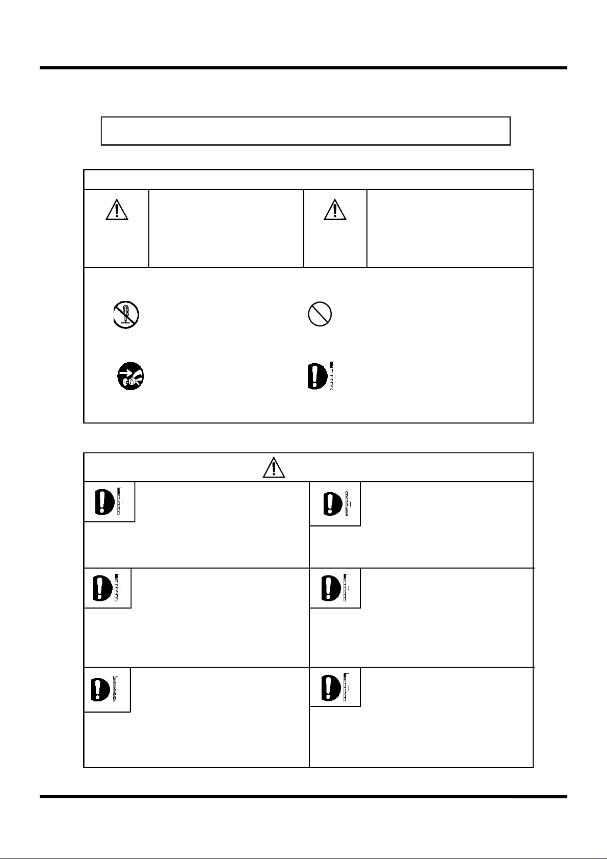
For your safety, please observe following items
◆ Please read [Cautions for Safety] carefully in advance and use the refrigerator correctly.
This indicates that death or
Serious injuries may occur
As a result of not observing
Warning
◆ Meaning of marking
this warning.
Don’t Disassemble.
Disconnect the power plug.
Do not install refrigerator in humid
environments.
◇ If electrical insulation were
weakened, it would cause electric
shock or fire outbreak.
Caution
Warning
This indicates that minor to
moderate injuries may occur
as a result of not observing
this warning.
Prohibited / Don’t try to do it.
Enforced / You should observe
instructions.
Before disposing of refrigerator,
remove the rubber packing of
the doors.
◇ Children can lock themselves
in the refrigerator and may be
suffocated.
When inserting the power plug,
the direction of the electrical cord
is downward.
◇ When the direction of cord is
inserted upward, it may be
damaged and causing short circuit
and overheat. then electric shock
or fire outbreak may occur.
When the power cord is damaged,
please make a call for a service.
◇ It may cause fire outbreak,
electric shock or short circuit.
When connecting the power
plug, make sure it is fastened
certainly.
◇ Electrical insulation will be
weakened and causing electric
shock or fire outbreak.
When you feel a combustible gas
leaking, air the area so that
the refrigerator does not exposed
to gas.
◇ A spark at an electrical contact
point may cause an explosion, fire
or burning damage.
1
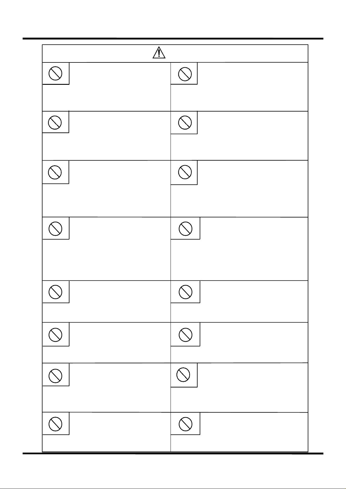
Warning
Don’t hold the power plug with
a wet hand.
◇ It may cause electric
shock.
Be sure the power supply is 220V.
◇ Otherwise, a fire outbreak,
electric shock or disorder may
be caused.
The power plug or cable shall not
be pressed by the refrigerator or
other things.
◇ Damage may be caused,
followed by a fire outbreak.
Don’t let the power cord touched
by a heater.
Don’t use a branched electrical outlet.
◇ Multi-branched power
connection may cause abnormal
overheat and a fire outbreak.
◇ Use a single-connection
electrical outlet with rated 220V
or more.
Don’t use a damaged power cord
or plug or a loose outlet.
◇ They may cause short circuit and
overheat, so that electric shock or a
fire outbreak may occur.
When pulling off the electric plug,
avoid holding only the cable.
◇ The cable may be damaged,
causing electric shock or a
fire outbreak.
◇ Be sure to hold the power plug
to pull it off.
Don’t put a container filled with water
on it.
◇ Damaged cord may cause a fire
outbreak or electric shock.
◇ If the cord is damaged, stop
using it and ask for a change by the
service center.
Don’t spill water on the main body
or inside.
◇ Electrical insulation may be
deteriorated, causing electric shock
or a fire outbreak.
Don’t hold the door and pull it down.
◇ The refrigerator may fall down
or your hand may be squeezed
and harmed.
Never disassemble or modify it.
◇ A fire outbreak or malfunctioning
may occur.
◇ If water is spilt, insulation of the
electrical parts may be
deteriorated, causing short circuit,
electric shock or a fire outbreak.
Don’t adjust the shelf with food
on it.
◇ It may fall down to hurt you.
Don’t climb over the refrigerator.
◇ It may be overturned and
hurt you.
Don’t let the power cord pressed by
heavy things nor pull or bend it hard.
◇ Damaged coating may cause a
fire or electric shock.
Don’t use flammable spray nearby.
◇ Spark at a contact point may
cause a fire outbreak.
Don’t put combustible inside.
◇ Thinner, benzene, LP gas and
adhesive may catch fire or
cause explosion.
2
Don’t put medicine or academic
materials inside.
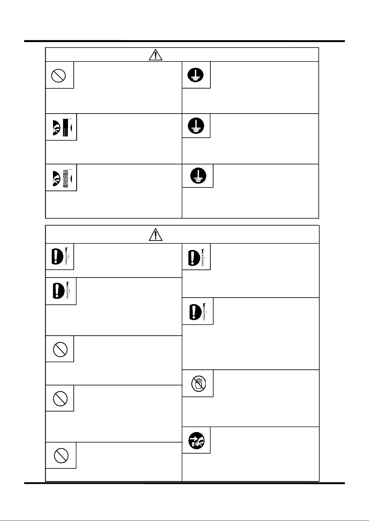
Warning
When the fuse is exchanged, use
one with the same capacity.
◇ Don’t put materials that strict
temperature control is needed for in
a domestic refrigerator.
When you put your hand in the
machine room at the rear bottom,
be sure to unplug the
power connection.
◇ Otherwise, electric shock or
burning may occur.
When changing the light inside, be
sure to disconnect the power.
◇ Electric shock may occur.
Caution
When changing the light inside,
wear gloves so that you may not to
be burned or hurt by a breaking.
When moving it, raise the
adjustment feet.
◇ Otherwise, fire may be caused.
Grounding shall not be onto a water
pipe, a gas pipe, a telephone line or
a lightening rod.
◇ Fire or electric shock may occur.
◇ For grounding, be sure to ask
the seller.
Solid grounding shall be made.
◇ Short circuit by a disorder may
cause electric shock.
◇ For grounding, be sure to ask
the seller.
Don’t eat odorous or
color-changed food.
◇ Long keeping even in the fridge
or Freezer may
spoil food.
◇ Otherwise, the floor may
be damaged.
◇ A protection cover shall be used
on a damage-prone floor.
Don’t put your hand under the
bottom of the refrigerator.
◇ If you do while cleaning, you
may get hurt on the sharp steel
sheet.
Don’t put your hand on the
compressor or the pipes at the
rear bottom.
◇ Those parts are hot while in or
right after operation and so they
may burn you.
Don’t put a bottle in the
Freezer.
◇ It may be broken and hurt you.
When moving it, hold the adjustment
feet and the rear upper part.
◇ When holding the rear upper
part, be careful not to let your
hand slip.
◇ If it slips, it may be hurt.
Don’t touch the food or containers
in the fridge or freezing
compartment with a wet hand.
◇ You may suffer from frostbite.
If it is not in use for long, unplug
the power cord.
◇ Otherwise, fire outbreak
may occur.
3
2. Product Specification
2-1. Product Specification
Items Product Specification
Model Name FRQ-19D... (Dispenser only ) FRQ-19F... ( Dispenser + H/bar )
Total Capacity 512ℓ
( Effective
Capacity
Freezing Compart. 4star: 134ℓ / 2star: 25ℓ
Fridge Compart. 353ℓ
External Size_mm
(WidthXDepthXHeight
Heating Device Rated Input 250 W
Refrigerator Kind Indirect cooling type
Cooling Media / Sealed Quant’y R600a ( 0.064kg ) or R-134a ( 0.160kg )
Climate Grade SN ~ T
Weight 97 kg 100 kg
912X795.8X1771
2-2. Electrical Part Specification
Items Product Specification
Model Name FRQ-19D... (Dispenser only ) FRQ-19F... ( Dispenser + H/bar )
Freezing Performance 4-Star
Evaporator FIN TYPE
Freezing
Parts
Condenser Forced circulation type
dryer MOLECULAR SIEVE XH-9
Capillary Tube IDΦ0.7 X 0.55t X L2,365
Defrost
ing
Parts
Defrosting Heater 250W
D-sensor (Type/
Return Temperature)
Temperature Fuse 250V / 10A / 77 (+0,-4)℃
PBN-43 / 13℃
4
Other
Electronic
Unit Spec.
Items Specification
Model Name FRQ-19D... (Dispenser only ) FRQ-19F... ( Dispenser + H/bar )
Main Fuse AC250V /12A
Home-bar Heater 230V / 10W (Control per RT & time)
Freezing Compart.(F) Fan Motor DC12V / Φ140
Condenser(C) Fan Motor DC12V / Φ150
Freezing Compart.(R) Damper DC12V
Switchable Room Damper -
Freezer Light LED ( DC12V / 1.20W )
Fridge Light LED ( DC12V / 1.69W )
Freez./Fridge Compart. Door Switch SP101B-2D1 (AC 250 V, 0.5A)
Home-bar Door Switch -
power cord AC250V 16A(VDE)
F / R-sensor N3RC-K32D / N3JC-K41A
ICING / FLOW-sensor N3JC-K35D-D94 / SH-F 110L
DC 12V / RS-D4
(REED S/W + MAGNET)
2-3. Controlled Temperature of the Freezing & Fridges
Freezer Fridge
Stage Display ON / OFF Stage Display ON / OFF
Weak -16 -12.0 / -16.0 Weak 8 9.4 / 9.9
Weak-to-medium1 -17 -14.8 / -18.8 Weak-to-medium1 7 8.5 / 8.9
Weak-to-medium2 -18 -15.8 / -19.8 Weak-to-medium2 6 7.4 / 7.9
Medium -19 -16.8 / -20.8 Medium 5 6.5 / 7.0
Medium-to-strong1 -20 -17.4 / -21.4 Medium-to-strong1 4 5.5 / 6.0
Medium-to-strong2 -21 -19.0 / -23.0 Medium-to-strong2 3 4.5 / 5.0
Strong -22 -22.0 / -26.0 Strong 2 3.5 / 3.9
Quick -22 - Quick 2 -
5
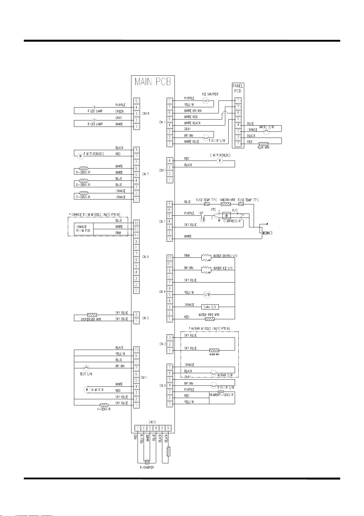
3. Wiring Diagram
3-1. Normal Compressor
6
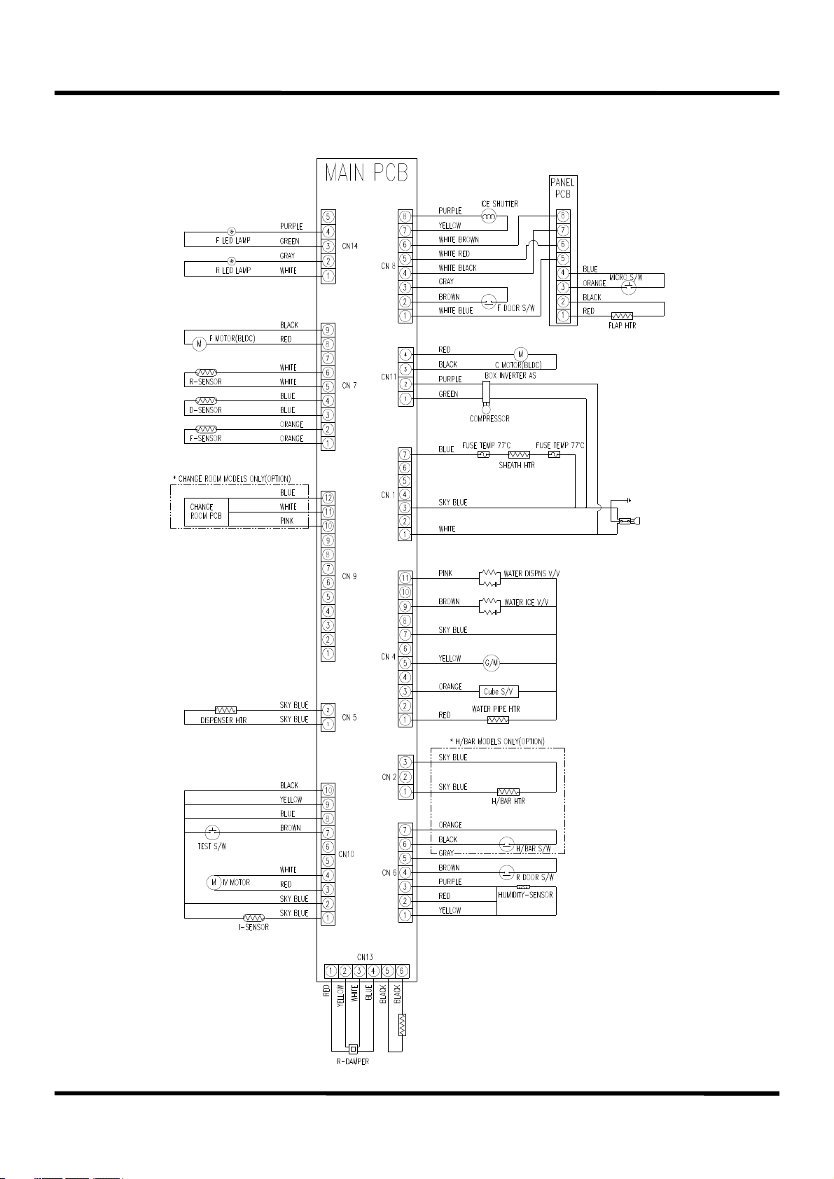
3-2. Inverter Compressor
7
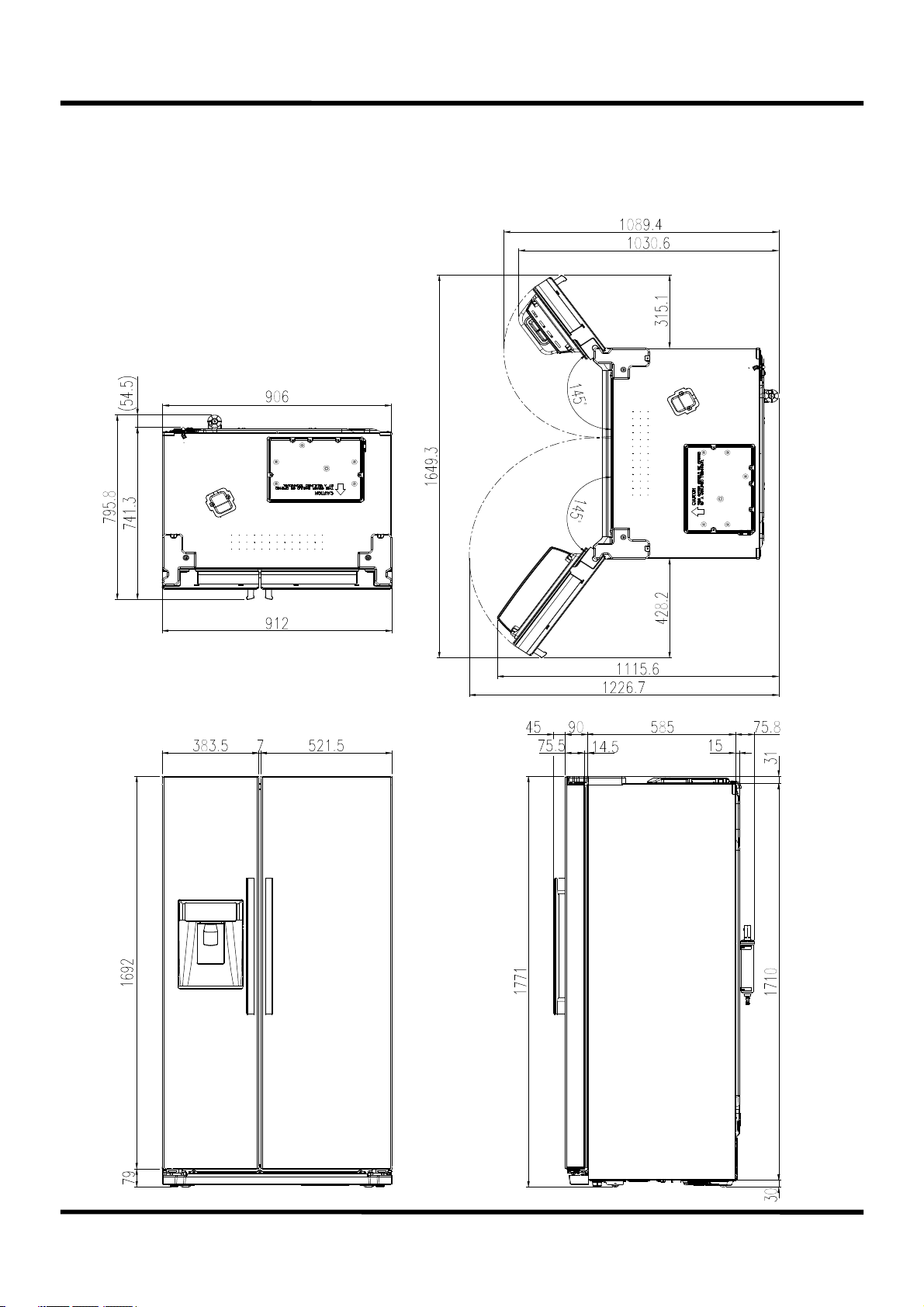
4. External Size and Names of the Refrigerator
4-1. FRQ-19D... (Dispenser only )
8
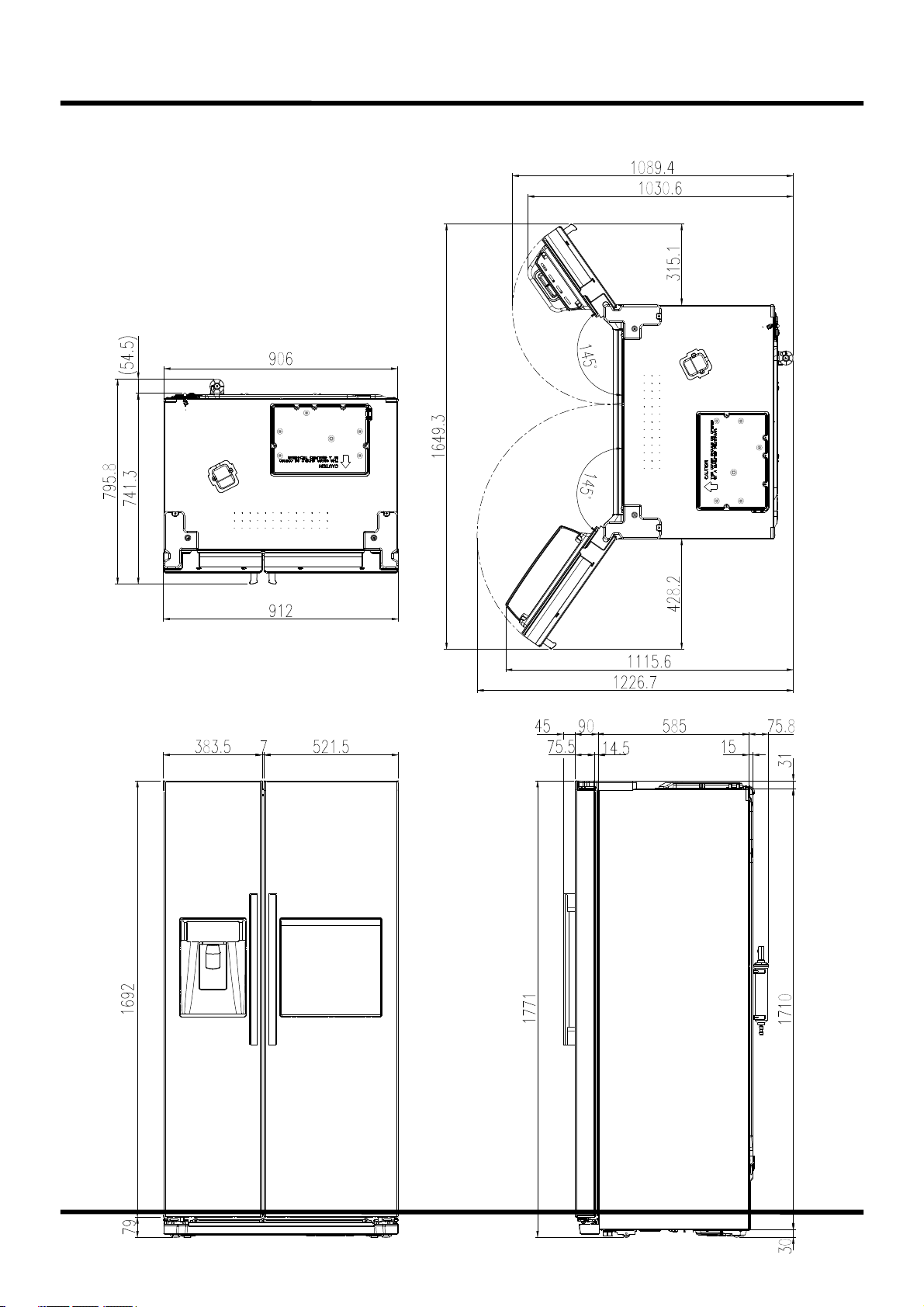
4-2. FRQ-19F... ( Dispenser + H/bar )
9
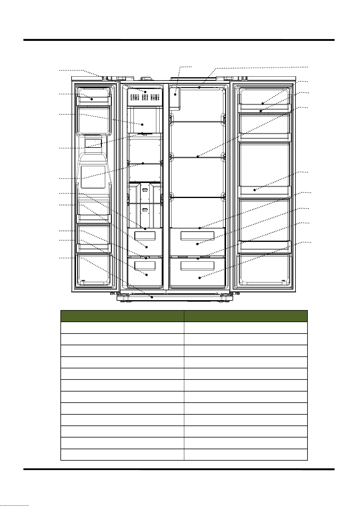
4-3. Part Name (FRQ-19D... )
2
1
3
4
5
6
7
8
9
13
14
20
11
15
12
16
17
18
19
10
Freezer Fridge
1. Freezer Pocket 11. Upper Fridge Pocket
2. Upper Ice Crusher Cover 12. Lower Fridge Pocket
3. Lower Ice Crusher Cover 13. Damper Cover
4. Freezer Internal Light 14. Fridge Internal Light
5. Freezer Shelf 15. Fridge Shelf
6. Dried Food Case Cover 16. Upper Vegetable Case Cover
7. Dried Food Case 17. Upper Vegetable Case
8. Meat/Fish Case Cover 18. Lower Vegetable Case Cover
9. Meat/Fish Case 19. Lower Vegetable Case
10. Front Cover 20. Egg Tray
10
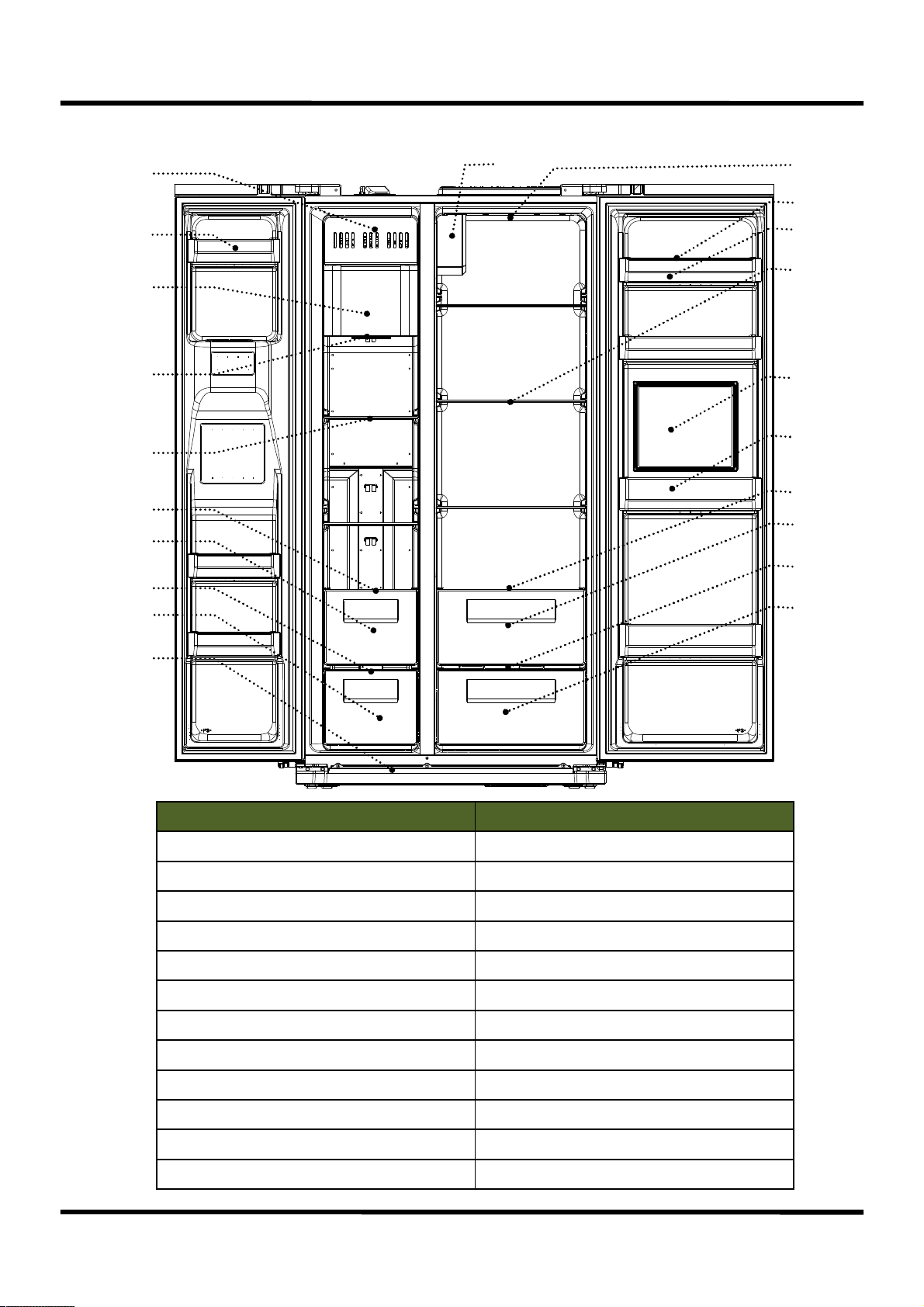
4-4. Part Name (FRQ-19F... )
1
2
3
4
5
6
7
8
9
13
14
21
11
15
20
12
16
17
18
19
10
Freezer Fridge
1. Freezer Pocket 11. Upper Fridge Pocket
2. Upper Ice Crusher Cover 12. Lower Fridge Pocket
3. Lower Ice Crusher Cover 13. Damper Cover
4. Freezer Internal Light 14. Fridge Internal Light
5. Freezer Shelf 15. Fridge Shelf
6. Dried Food Case Cover 16. Upper Vegetable Case Cover
7. Dried Food Case 17. Upper Vegetable Case
8. Meat/Fish Case Cover 18. Lower Vegetable Case Cover
9. Meat/Fish Case 19. Lower Vegetable Case
10. Front Cover 20. Home Bar
21. Egg Tray
11
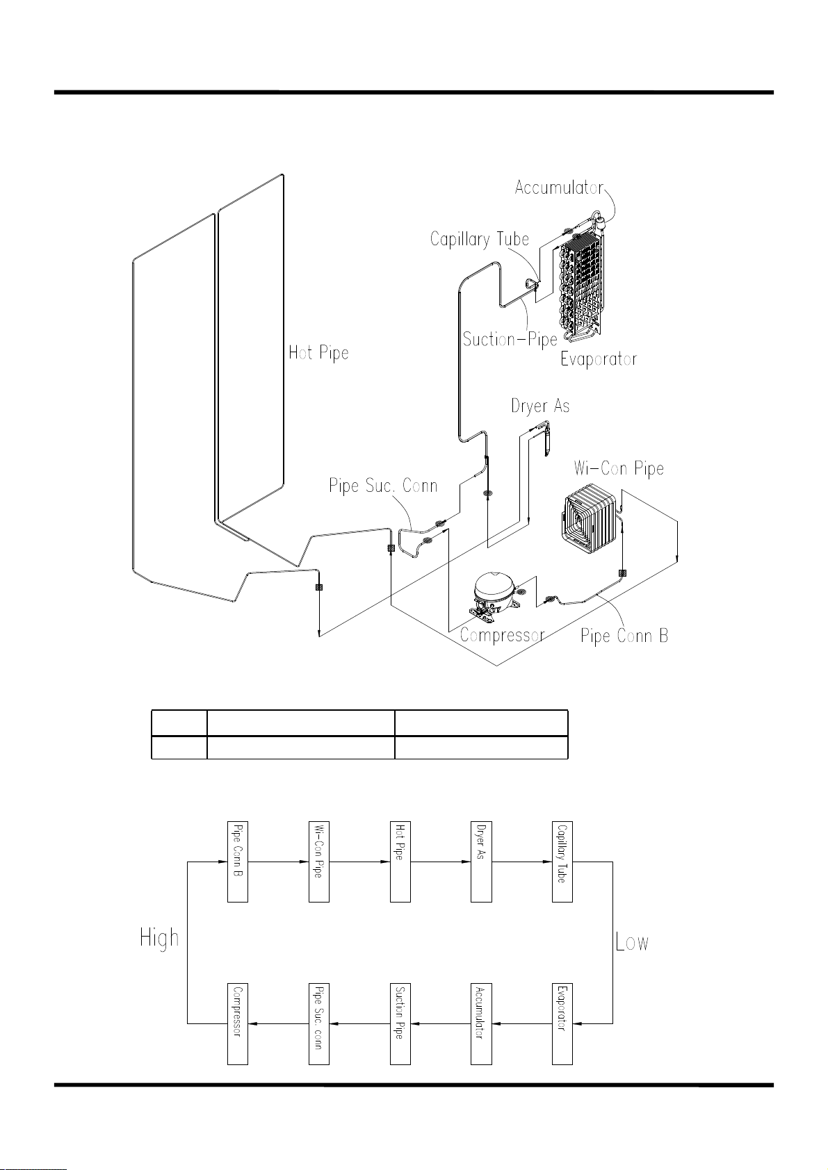
5. Refrigeration Cycle
▶ Welding Specification
●
■
▶ Refrigerent Flow
Copper Soldering (Ag 3%) 7 Points
Silver Soldering (Ag 30%)
3 Points
12
6. Functions & Usage of the Refrigerator
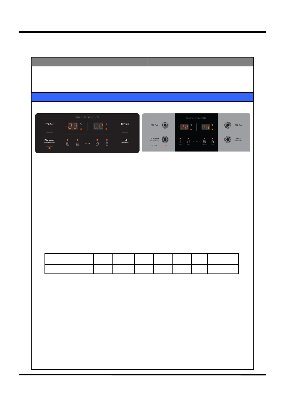
6-1. Display ( None crusher model )
Input Parts Control Object
1. F-PCB Button
2. Freezing Adjustment, Fridge Adjustment
3. lock Button
Contents
1. “Freezing Adjustment” Button
1) Press “Freezing Adjustment” Button to have it run in staged temperature adjustment (7 stages)
and quick freezing (max. limit 24 hours). In quick freezing running, “ * “ is on; otherwise, it is off.
2
) Initial default setup at the power connection is “medium” stage, with the setup temperature -19℃ displayed.
Order of display:
Medium(-19℃)→Medium-to-strong1(-20℃)→Medium-to-strong2(-21℃)→Strong(-22℃)
→Quick(-22℃)→Weak(-16℃)→Weak-to-medium1(-17℃)→Weak-to-medium2(-18℃)
3) When Quick freezing is chosen, “Quick Icon” flickers 6 times before it is lighted, with the setup
temperature displayed the same as in dial “Strong”.
4) Freezing Adjustment stages & displays
1.Display
Adjustment Stages W WM1 WM2 M MS1 MS2 S Q
Setup Temperature(℃) -16 -17 -18 -19 -20 -21 -22 -22
5) When Quick freezing is finished, Dial will automatically turn to “Medium(-19℃)”.
2. “Fridge Adjustment” Button
1) Press “Fridge Adjustment” Button to have it run in staged temperature adjustment (7 stages)
and quick fridge(max. limit 40 minutes). In quick freezing running, “ * “ is on; otherwise, it is off.
2) Initial default setup at the power connection is “medium” stage, with the setup temperature 2℃ displayed.
Order of display:
Medium(4℃)→Medium-to-strong(3℃)→Strong(2℃)→Quick(2℃)→Weak(8℃)→Weak-to-medium1(7℃)
→Weak-to-medium2(6℃)→Weak-to-medium3(5℃)
3) When Quick operation is chosen, “Quick Icon” flickers 6 times before it is lighted, with the setup
temperature displayed the same as in dial “Strong”.
13
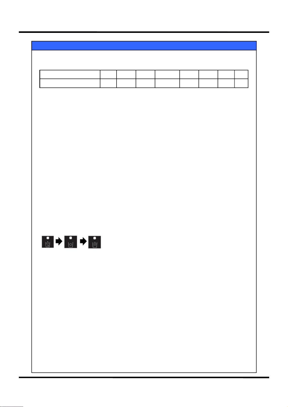
2. “Fridge Adjustment” Button
4) Fridge Adjustment stages & displays
Contents
Adjustment Stages
Setup Temperature(℃)
W WM1 WM2 WM3 M MS S Q
8 7 6 5 4 3 2 2
5) When Quick fridge is finished, Dial will automatically turn to “Medium(4℃)”.
3. “lock” Function Button
1) lock Setup
- Press “lock” button for 0.5 seconds to have the “lock Icon” On
- When “lock” is set up, no key input (including the dispense switch) is possible nor the buzzer will ring.
2) Cancel: Press the “lock” function button for 3 seconds to cancel the lock state.
4. Power Save Function
All LED will be turned off one minute after a final key input or a door closing
(with Lock LED and Water/Ice LED not included).
5. Dispenser select
Led above the icon will light up to indicate your selection.
1) 1st‘Dispenser’ button, water is available.
2) 2nd‘Dispenser’ button, cubed ice is available.
rd
3) 3
‘Dispenser’ button, dispenser lock.
14
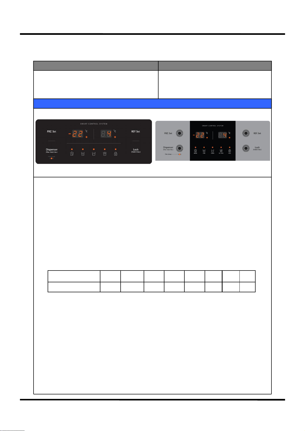
6-1. Display ( Crusher model )
Input Parts Control Object
1. F-PCB Button
2. Freezing Adjustment, Fridge Adjustment
3. lock Button
Contents
1. “Freezing Adjustment” Button
1) Press “Freezing Adjustment” Button to have it run in staged temperature adjustment (7 stages)
and quick freezing (max. limit 24 hours). In quick freezing running, “ * “ is on; otherwise, it is off.
2
) Initial default setup at the power connection is “medium” stage, with the setup temperature -19℃ displayed.
Order of display:
Medium(-19℃)→Medium-to-strong1(-20℃)→Medium-to-strong2(-21℃)→Strong(-22℃)
→Quick(-22℃)→Weak(-16℃)→Weak-to-medium1(-17℃)→Weak-to-medium2(-18℃)
3) When Quick freezing is chosen, “Quick Icon” flickers 6 times before it is lighted, with the setup
temperature displayed the same as in dial “Strong”.
4) Freezing Adjustment stages & displays
1.Display
Adjustment Stages W WM1 WM2 M MS1 MS2 S Q
Setup Temperature(℃) -16 -17 -18 -19 -20 -21 -22 -22
5) When Quick freezing is finished, Dial will automatically turn to “Medium(-19℃)”.
2. “Fridge Adjustment” Button
1) Press “Fridge Adjustment” Button to have it run in staged temperature adjustment (7 stages)
and quick fridge(max. limit 40 minutes). In quick freezing running, “ * “ is on; otherwise, it is off.
2) Initial default setup at the power connection is “medium” stage, with the setup temperature 2℃ displayed.
Order of display:
Medium(4℃)→Medium-to-strong(3℃)→Strong(2℃)→Quick(2℃)→Weak(8℃)→Weak-to-medium1(7℃)
→Weak-to-medium2(6℃)→Weak-to-medium3(5℃)
3) When Quick operation is chosen, “Quick Icon” flickers 6 times before it is lighted, with the setup
temperature displayed the same as in dial “Strong”.
15
2. “Fridge Adjustment” Button
4) Fridge Adjustment stages & displays
Contents
Adjustment Stages
Setup Temperature(℃)
W WM1 WM2 WM3 M MS S Q
8 7 6 5 4 3 2 2
5) When Quick fridge is finished, Dial will automatically turn to “Medium(4℃)”.
3. “lock” Function Button
1) lock Setup
- Press “lock” button for 0.5 seconds to have the “lock Icon” On
- When “lock” is set up, no key input (including the dispense switch) is possible nor the buzzer will ring.
2) Cancel: Press the “lock” function button for 3 seconds to cancel the lock state.
4. Power Save Function
All LED will be turned off one minute after a final key input or a door closing
(with Lock LED and Water/Ice LED not included).
5. Dispenser select
Led above the icon will light up to indicate your selection.
1) 1st‘Dispenser’ button, water is available.
2) 2nd‘Dispenser’ button, cubed ice is available.
rd
3) 3
‘Dispenser’ button, crushed ice is available.
4) 4th‘Dispenser’ button, dispenser lock.
16
6-2. Freezer Temperature Adjustment
Input Parts Control Object
1. Freezer Temperature Adjustment Button
2. F-Sensor
1. Comp
2. F-Fan
Contents
1. Press the Freezer button to adjust the Freezer temperature.
Medium(-19℃)→Medium-to-strong1(-20℃)→Medium-to-strong2(-21℃)→Strong(-22℃)
→Quick(-22℃)→Weak(-16℃)→Weak-to-medium1(-17℃)→Weak-to-medium2(-18℃)
2. Comp and F-fan are controlled by Dial On / Off.
3. On / Off Diff of the Freezer: 4.0℃
Medium Off point of the Freezer : -20.8℃
4. Freezer Diff for each step
1) Weak → Weak-to-medium1 : 3.0 deg.
2) Weak-to-medium1 → Weak-to-medium2 → Medium : 1.0 deg.
3) Medium → Medium-to-strong1 : 0.6 deg.
4) Medium-to-strong1 → Medium-to-strong2 : 1.4 deg.
5) Medium-to-strong2 → Strong : 3.0 deg.
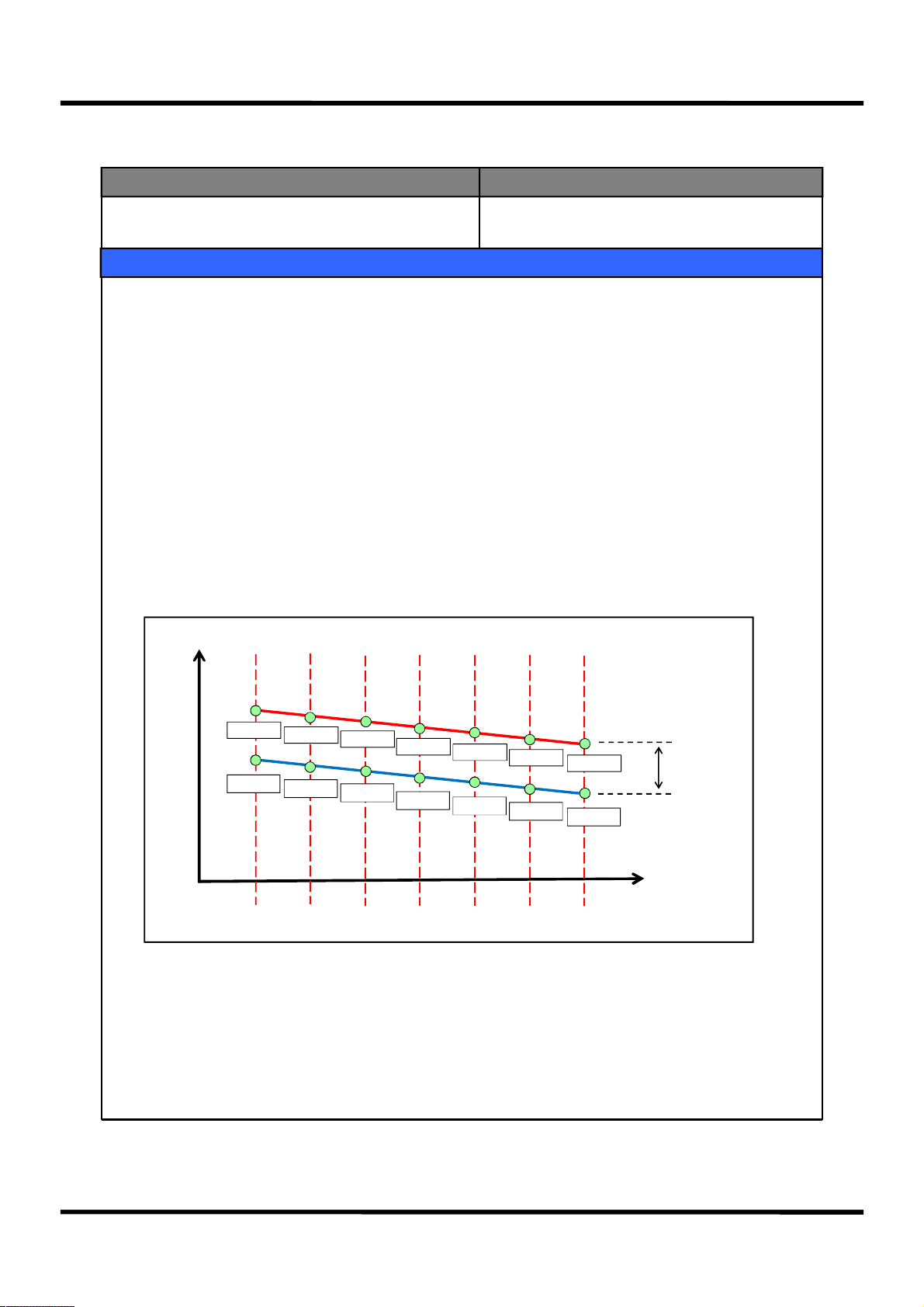
5. Control Point for each Dial (F-Sensor Detection Temperature)
temp.
-8.8 ℃
-13.3 ℃
-12.0 ℃
-16.3 ℃
-13.1 ℃
-17.2 ℃
-14.1 ℃
-18.2 ℃
-15.1 ℃
-19.1 ℃
-17.0 ℃
-20.9 ℃
-18.9 ℃
-22.8 ℃
ON Point
ON/OFF DIFF
OFF Point
MODE
Weak
(Weak to medium1,2)
Medium (Medium to strong1,2)
6. Quick Freezing
1) In Quick Freezing, it is run by ‘Strong’ dial of F-Dial for the limited time(24 hours).
2) When Quick Freezing is closed by the time limit or the F-Sensor is Off point, it is run with the ‘Medium’
dial value of the F-Dial.
3) During a Quick Freezing operation, defrosting cannot be started. If Quick Freezing is set up in defrosting,
Quick Freezing will be run after the defrosting.
Strong
17
6-3. Fridge Temperature Adjustment
Input Parts Control Object
1. Fridge Temperature Adjustment Button
2. R-Sensor
1. Comp
2. F-Fan
3. Damper
Contents
1. Press the Freezer button to adjust the setup temperature of the Freezer.
Medium(4℃)→Medium-to-strong(3℃)→Strong(2℃)→Quick(2℃)→Weak(8℃)→Weak-to-
medium1(7℃)→Weak-to-medium2(6℃)→Weak-to-medium3(5℃)
2. Comp and F-fan are controlled by the On / Off points of each Dial.
3. On / Off Diff of the Fridge: 0.5℃
Fridge “Medium” Off point: 5.5℃
4. Fridge Step Diff
1) Each Step Diff: 1 deg.
(At low room temperature (RT-S of 19℃ or less), Dial ‘Medium, Medium-to-strong, Strong’ will lower the On/Off
points by 1℃, while at high room temperature (RT-S of 41℃ of more), Dial ‘Medium, Medium-to-strong,
Strong’ will lower the On/Off points by 0.3℃.)
5. Prevention of Weak Cooling
1) When Weak Cooling is detected, Comp is turned on, regardless of F-Sensor.
2) When R-sensor reaches R-Damper Close point, Comp is controlled by the F-sensor and R-Damper is Close.
3) Weak Cooling detection point: R-Damper Close of each Mode + 7℃
4) Weak Cooling cancellation point: the same as the R-Damper Close point of each Mode
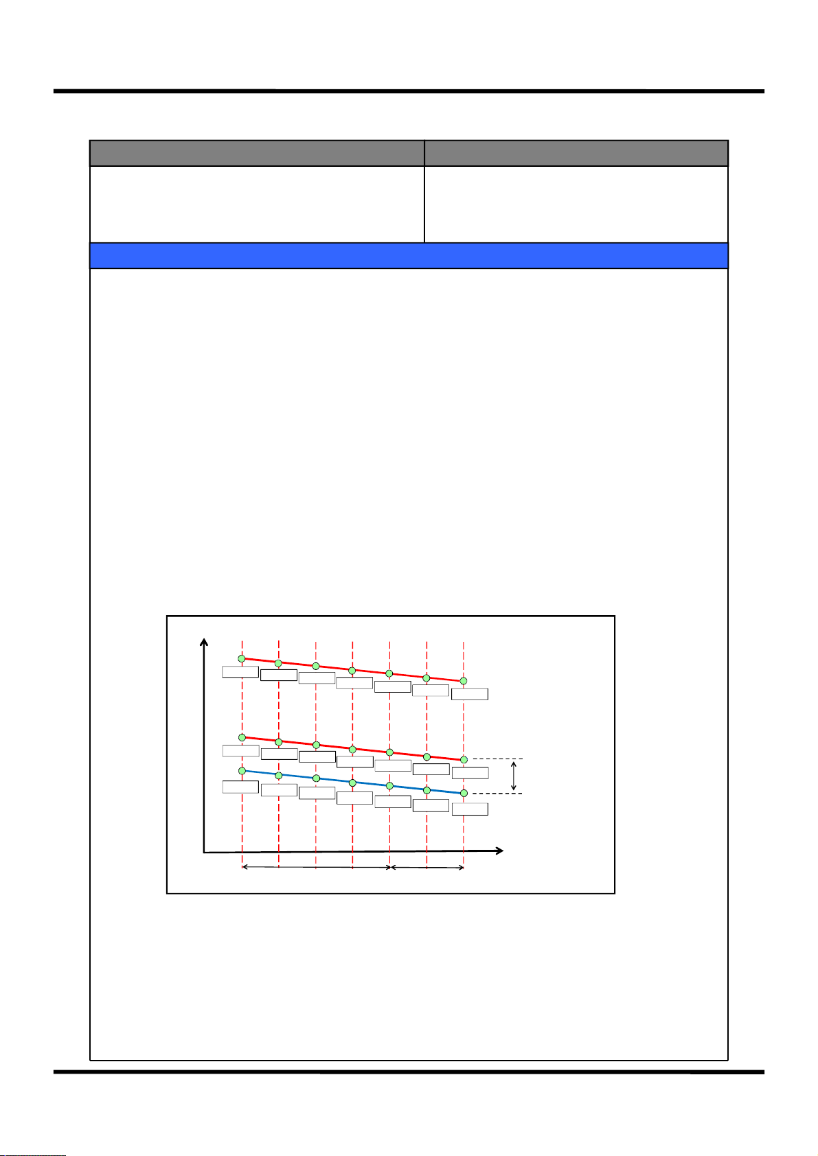
6. Control Point for each Dial (R-Sensor detection temperature)
temp.
16.5 ℃
15.5℃
9.9℃
9.4℃
Weak
14.5℃
8.9℃
7.9℃
8.5℃
7.4℃
STEP DIFF
(Weak to medium1,2,3)
13.5 ℃
7.0℃
6.5℃
12.5℃
6.0℃
5.5℃
Medium
11.5℃
5.0℃
4.5℃
STEP DIFF
Medium to strong
10.5℃
3.9℃
3.5℃
Strong
Week Cooling c heck
(OFF Point + 7.0 deg)
ON Point
ON/OFF DIFF
(0.5 deg)
OFF Point
MODE
7. Quick Fridge
1) In Quick Fridge, it is run in ‘Strong’ dial of the R-Dial for the limited time (40 minutes).
2) Until the R-sensor reaches the Overcooling Off point(-7deg.), R-Damper is open and F-Fan /
Comp are On.
3) After the Overheating Off point is reached, it is run by Dial “strong” On/Off points until 40
minutes of Quick Fridge is finished.
4) When the Quick Fridge is finished, it will turn to normal operation.
18
6-4. Fan Control at each Mode
Input Parts Control Object
1. R-Sensor
2. F-Sensor
1. F-Fan
2. C-Fan
Contents
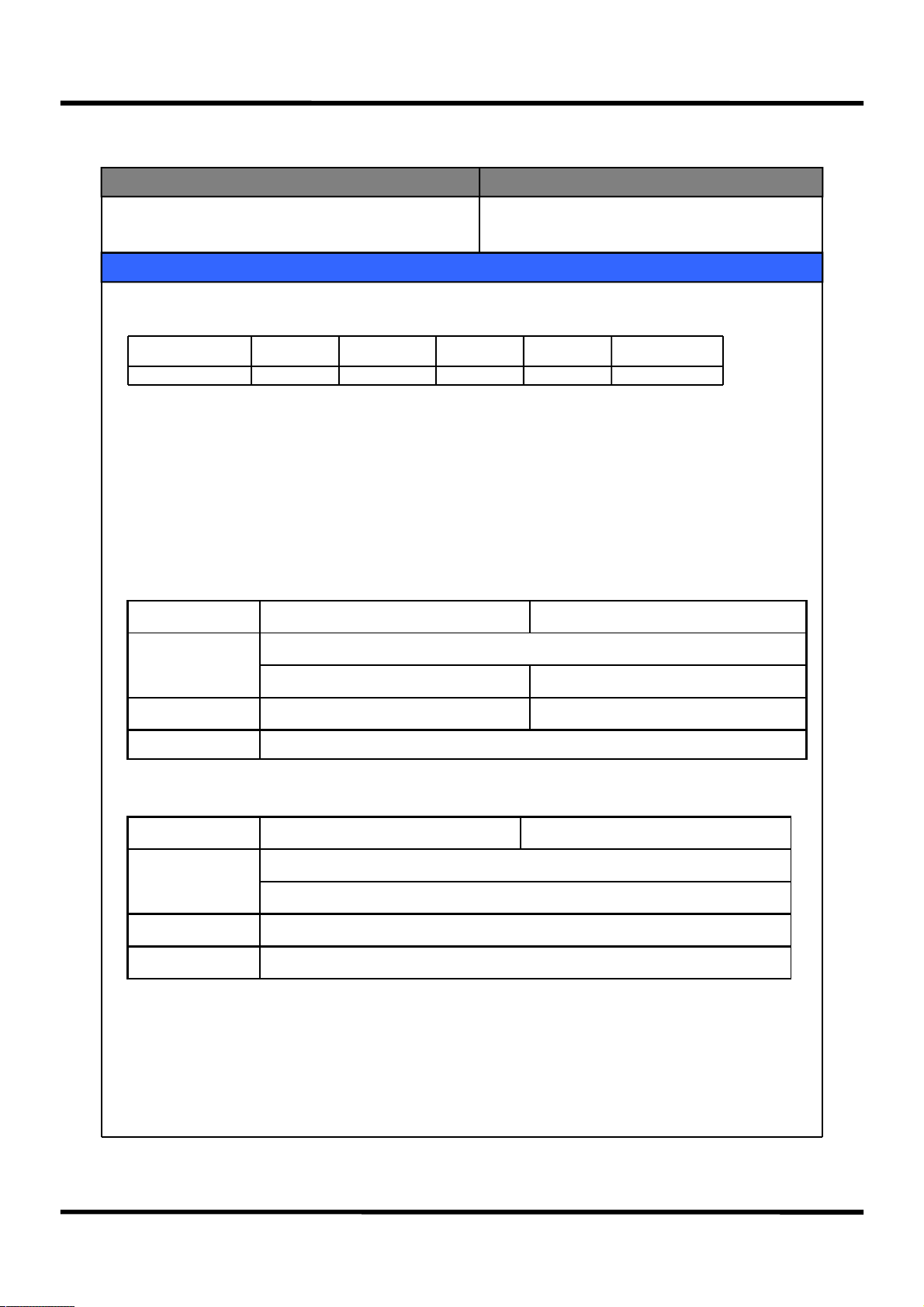
1. Fan RPM for each control Mode
1) F-Fan Motor voltage
Control Mode Normal Quick Freezing
F-FAN voltage 10V 12V 12V 13V 13V
Load
Response1
Load
Response2
RT-S 39℃ or more
● Normal Control ☞ Low operation mode with soft noise
● Load Response ☞ Operation mode when the temperature in the compartments is deemed escalating by
usage condition.
2. Load Response Mode
1) Purpose: To recover the temperature of the compartment escalated by overload or an opening of the
door.
2) Display Method: There is no separate display.
3) Conditions for Load Response1 startup and cancellation, and its control method
Freezer Load Response Fridge Load Response
Startup Condition
1. F/R-Door opening of 30 seconds or more
2. F/S On Point + 5deg. or more detected 2. R/S On Point + 5deg. or more detected
Cancel. Condition F-Sensor value < Off point R-Sensor value < Off point
Control Method Comp RPM is controlled to change to the next higher stage of RPM
4) Conditions for Load Response2 startup and cancellation, and its control method
Freezer Load Response Fridge Load Response
Startup Condition
Cancel. Condition Cancelled if the defrosting is started
Control Method Operation with Comp RPM being 3990
1. Load Response1 at RT-S 29 ℃ or less
2. When COMP has continuously operated for 6 hours
19
6-5. Defrosting
Input Parts
1. Accumulated Comp Operation Time
2. Time Lapse since a Comp On/Off
1. Comp
2. F-Fan
Control Object
3. Defrosting Heater
4. Damper
Contents
1. Defrosting Startup Condition
1) Accumulated Comp Operation Time: If it passes 8,10,12,~ 40 hours and, at the same time, various errors take place or
the accumulated F-Door Opening is 2 minutes or more, the defrosting will be started.
2) If the accumulated F/R-Door Opening time is 2 minutes or more and the operation rate in 2 hours is 85% or more, the
defrosting will be started.
3) Total (Comp On Time + Comp Off Time) time : If it is 50 hours, the defrosting will be started.
4) If accumulate Comp operation time is 24 hours, the defrosting will be started.
* Various Errors : R1, F1, D1, F3, RT/S, C1, Door error.
2. General Defrosting Procedure
1) Time limit is 50 minutes (Comp, F-fan operation)
Precool
Heater
Defrosting
2) When the lime limit of 50 minutes passes, F-Sensor < -27℃, or there is Error F3,
Precool will end.
* There is no Precool in a general Defrosting (but only in a power consuming mode).
1) When D-Sensor ≥ 13℃, Defrosting Heater will be Off.
2) When the Defrosting heater turns off by the time limit (60 minutes), there will be an
F3-Error.
3) If there is a D-Sensor Error, the Defrosting Heater will be on, with the time limit of 30 min.
4) Process Time Limit
① 30min.: At a D-Error, each heater is on for 30/10 min.
② 60min.: When defrosting starts at a normal control state, the time limit will be 60min.
1) Pause Time = 10min.
Pause
2) In the pause time, Defrosting Heater, Comp and F-Fan is off.
3) During the pause time, Comp is off regardless of the R-Sensor temperature.
Fan Delay
2) Immediately after the pause, only the Comp is on, with the Heater off.
3. Power consuming mode starting (Average operation rate before a Defrosting is 80% or less)
1) If D-Sensor ≥ 9℃, the Defrosting Heater will be off.
2) Pause time is 10min.
3) After a Precool mode is proceeded, Heater-on mode will start.
4. Electronic Unit Control State & Time Limit for Each Mode
Precool D-HTR Defrosting Pause Fan Delay
Comp On Off Off On/Off
F-Fan On Off Off Off
D-HTR Off On Off Off
Time Limit 50min. 60min. 10min. 5min.
20
1) Fan Delay Time = 5min.
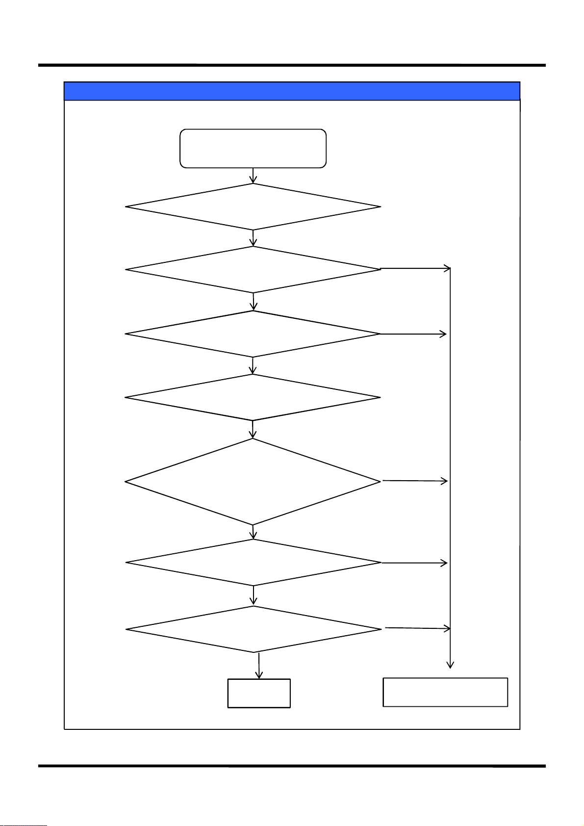
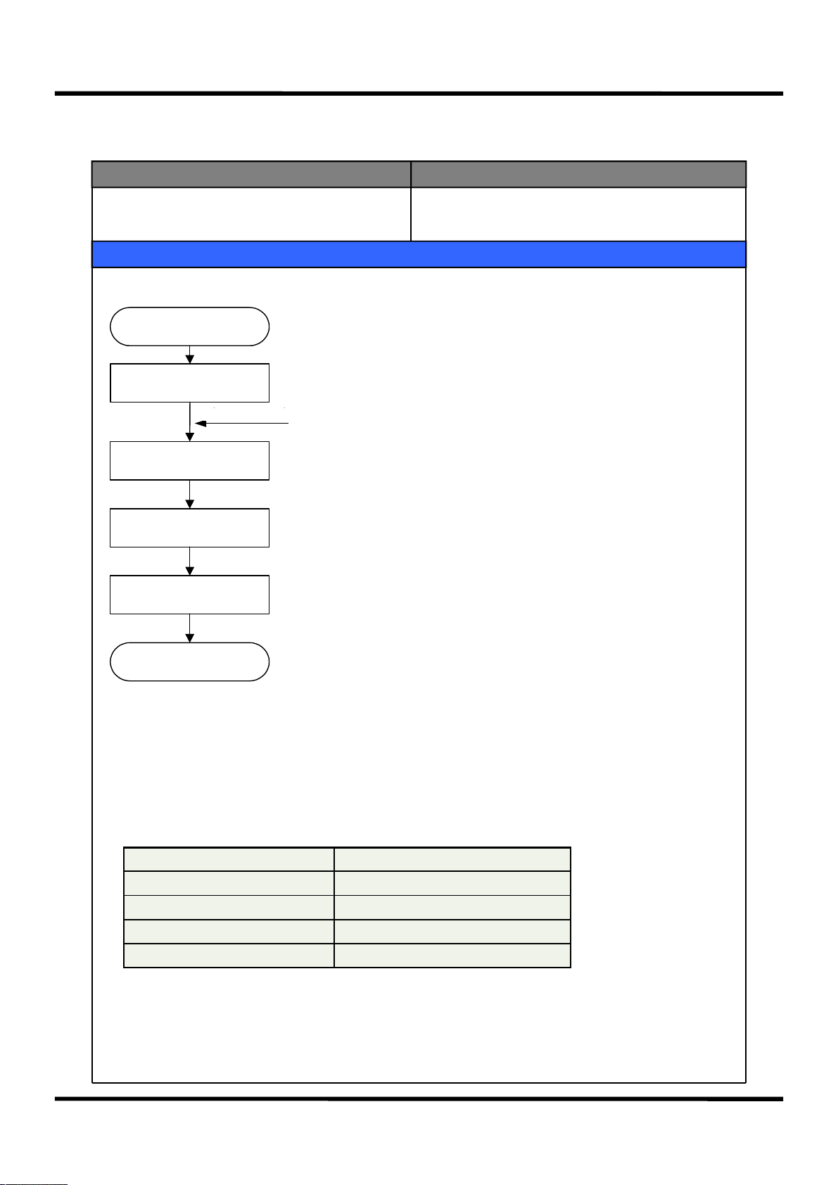
5. Defrosting Flow Decision
Contents
START
Comp. operation accumulated > 2 hours
YES
Total time(Comp On + Comp Off) > 50 hours
RT < 14℃ &
Total time(Comp On + Comp Off) > 24 hours
YES
Comp. operation accumulated > 8 hours
NO
(Comp. operation accumulated > 24 hours
NO
Any error ?
YES
YES
YES
Total F/R door open time > 2 min
END
21
YES
Defrost Mode Start
6-6 Initial Defrosting
Input Parts Control Object
1. D-Sensor
2. Initial Power Supply
Contents
1. If D-Sensor ≤ 3.5℃ when the initial power supply begins, Defrosting mode will start.
2. Defrosting is made per D-Sensor.
3. When in initial Defrosting, Comp is delayed by 6min.
1. Defrosting Mode
6-7 Short Circuit Operation
Input Parts Control Object
1.Front PCB
Contents
1. Starting: Press “Fridge Adjustment” + “Freezing Adjustment” 10 times in the “Locked” state.
2. Control Method: Comp & F/C-Fan continuous operation. R Damper Open
3. Operation Display: “Co” displayed at Error Display Mode (Refer to Error Display)
4. Cancellation: Automatically canceled 10 hr after starting
1. Electronic Units
6-8. Comp RPM Control ( Inverter compressor model only )
Input Parts Control Object
N/A
Contents
1. Comp RPM is changed per RT-Sensor & Set operation state
Temperature Condition
Normal Operation 1800 RPM 2550 RPM 3600 RPM 3990 RPM
Load Response1 2550 RPM 3600 RPM 3990 RPM 3990 RPM
Load Response2 3990 RPM 3990 RPM 3990 RPM 3990 RPM
Quick Operation 3600 RPM 3600 RPM 3600 RPM 3990 RPM
Short Circuit Operation 3990 RPM 3990 RPM 3990 RPM 3990 RPM
2. For 5 min. after an initial power supply, 1800RPM (lowest speed) operation
~29℃
29℃ ~ 35℃ 35℃ ~ 41℃ 41℃ ~
1.Comp
22
6-9. Prevention of Comp Re-start
Control ObjectInput Parts
N/A 1.Comp
Contents
1. For 6 min. after Comp is off, it will not re-start even though there is a Comp On condition occurring.
6-10. Time Shortening Function
Input Parts Control Object
1. Main PCB 1. Electronic Units
Contents
1. 1 min. Shortening: Click “Fast Key” of Main PCB.
2. 30 min. Shortening: Press “Fast Key” continuously and it will be shortened by 30 min. every 2.5 seconds
with a short buzzer beeping.
3. Usage Example: May be used to shorten unnecessary time.
(6 min. Pause function, Fan Delay function)
6-11. Buzzer Function
Input Parts Control Object
1. Front PCB Button
2. Door Switch
3. Initial Power Supply
Contents
1. Buzzer beeps as Front PCB is manipulated.
2. Buzzer beeps 3 sec. after an initial power supply.
3. Buzzer beeps at a power consuming mode forced Defrosting, short-circuit operation, A/S forced Defrosting.
1. Buzzer
4. Buzzer beeps when you press a button as you are fine-tuning the Freezer
/ Fridge.
5. Buzzer beeps every minute when a Door is open (for 5 min.).
23
6-12. Electronic Unit Delay Time
Control ObjectInput Parts
1.Comp On / Off
Contents
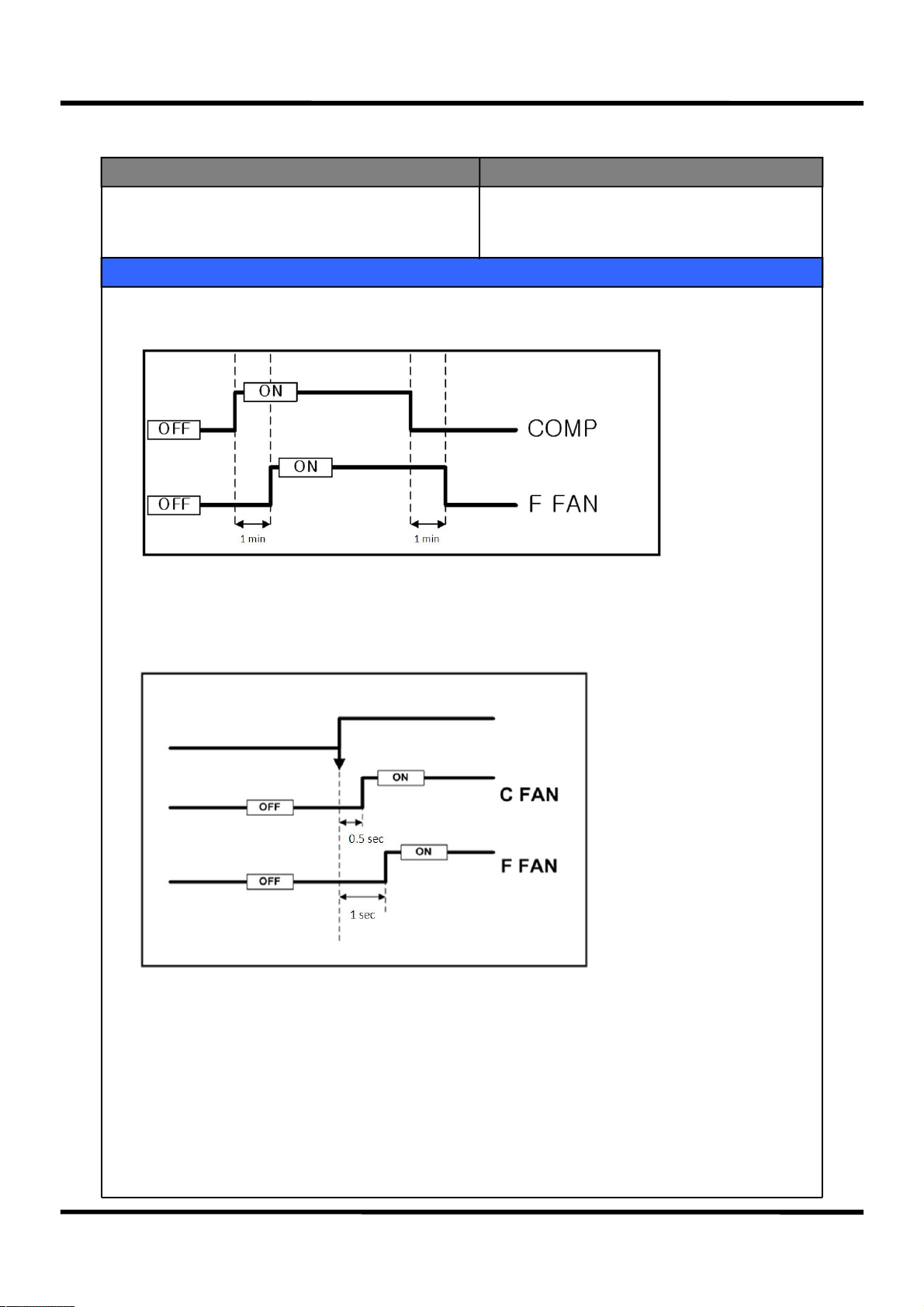
1. Comp / C-Fan / F-Fan
1) F-Fan Time Delay function at Comp On/Off (F-FAN on/off 1 min. after Comp on/off).
2) C-Fan : On 0.5 sec. after an On condition occurring
3) F-Fan : On 1.0 sec. after an On condition occurring
1.Comp
2.F/C-Fan
24
6-13. Internal Light Control Function
Control ObjectInput Parts
1. F Door
2. R Door
3. Home bar Door (option)
Contents
1. R Compartment Light Control
1) R Compartment Light is on/off immediately after a R Door Switch Open / Close signal detection.
2) But if opened state continues for 10 min. after a R Door Switch detects Opening, R Compartment light
will turn off even though there is no Close signal detected.
3) When opening is detected continuously for 1 hr. or more, “dr” Error is displayed and the functions related
to the Door Switch detection will be ignored.
2. F Compartment Light Control
1) F Compartment Light is on/off immediately after a F Door Switch Open / Close signal detection.
2) But if opened state continues for 10 min. after a F Door Switch detects Opening, F Compartment light
will turn off even though there is no Close signal detected.
3) When opening is detected continuously for 1 hr. or more, “dF” Error is displayed and the functions related
to the Door Switch detection will be ignored.
1. F/R Compartment Lights
3. R Compartment Light Control by Home Bar
1) R Compartment Light will be on/off immediately after a Home bar Door Switch Open/Close signal detection.
2) But if opened state continues for 10 min. after a Home bar Door Switch detects Opening, R Compartment
light will turn off even though there is no Close signal detected.
3) When opening is detected continuously for 1 hr. or more, “dH” Error is displayed and the functions related
to the Door Switch detection will be ignored.
25
6-14. DEMO Function
Input Parts Control Object
1. Fridge Button
2. Freezer Button
Contents
1. Starting
Press “fridge adjustment” button at the ”Locked State” and press “Choose Freezing” 5 times.
2. Control Method
1) Electronic units will all be off.
2) But if the Freezer and Fridge doors are open, the pertinent Fan will be on.
Door Open → Fan On , Door Close → Fan Off
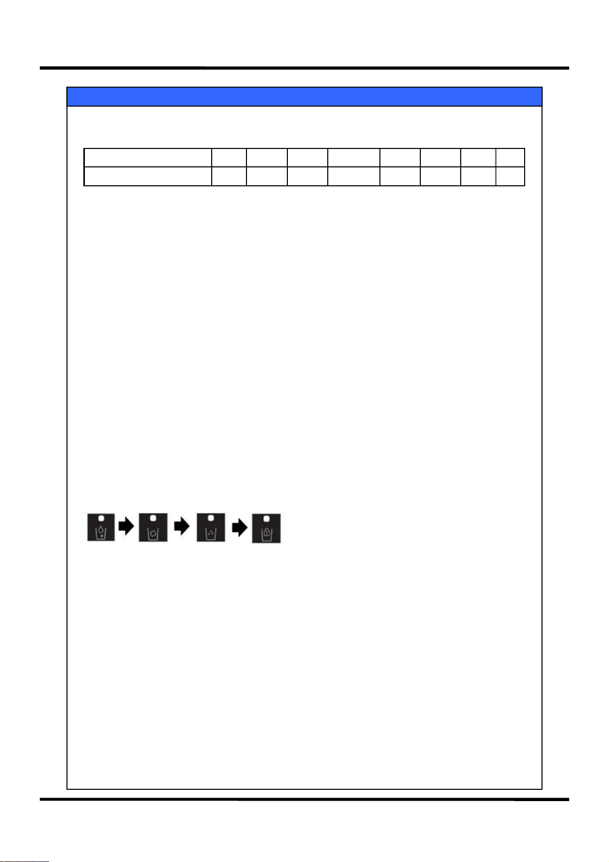
3)
Display
Freezing and Fridge temperature Display for each stage → Quick Icon On → Water Icon On →
Cube Icon On → Ice Maker Lock Icon
3. Cancellation
1) Press Fridge Adjustment + Choose Freezing 5 times.
2) Reset Power Supply.
1. Comp
2. F-Fan
3. Heater
6-15. Weak Cooling Option
Control ObjectInput Parts
1. J1,J2 on the Main PCB
Contents
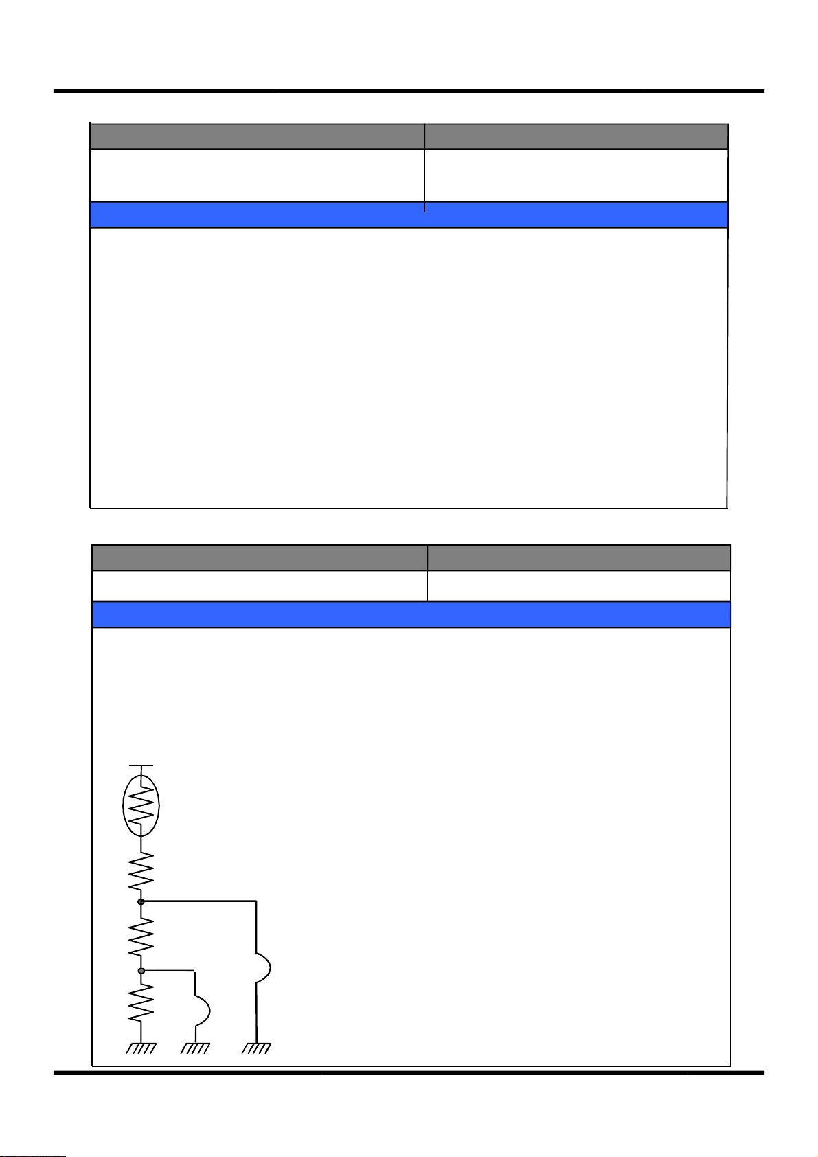
1. R-Sensor Off Point Adjustment (Maximum 3℃ down)
2. When weak cooling occurs, adjustment is made as following so as to make A/S easy.
1) Resistance(R36) : R-Sensor Standard Resistance at normal operation (31.4K)
2) Resistance(R37) : Standard Resistance 2K up by J1 cutting at weak cooling (1.5℃down)
3) Resistance(R38) : Standard Resistance 4K up by J1 & J2 cutting at weak cooling (3.0℃down)
R-SENSOR
R36
R36 = Medium OFF Point
R37
R36 + R37 = Medium OFF Point - 1.5 deg.
R36 + R37 + R38 = Medium OFF Point - 3.0 deg.
J1
1. R-Sensor “Medium” Off Point Standard Resistance
R38
J2
26
6-16. Automatic Ice Machine
Input Parts
N/A Automatic Ice Machine
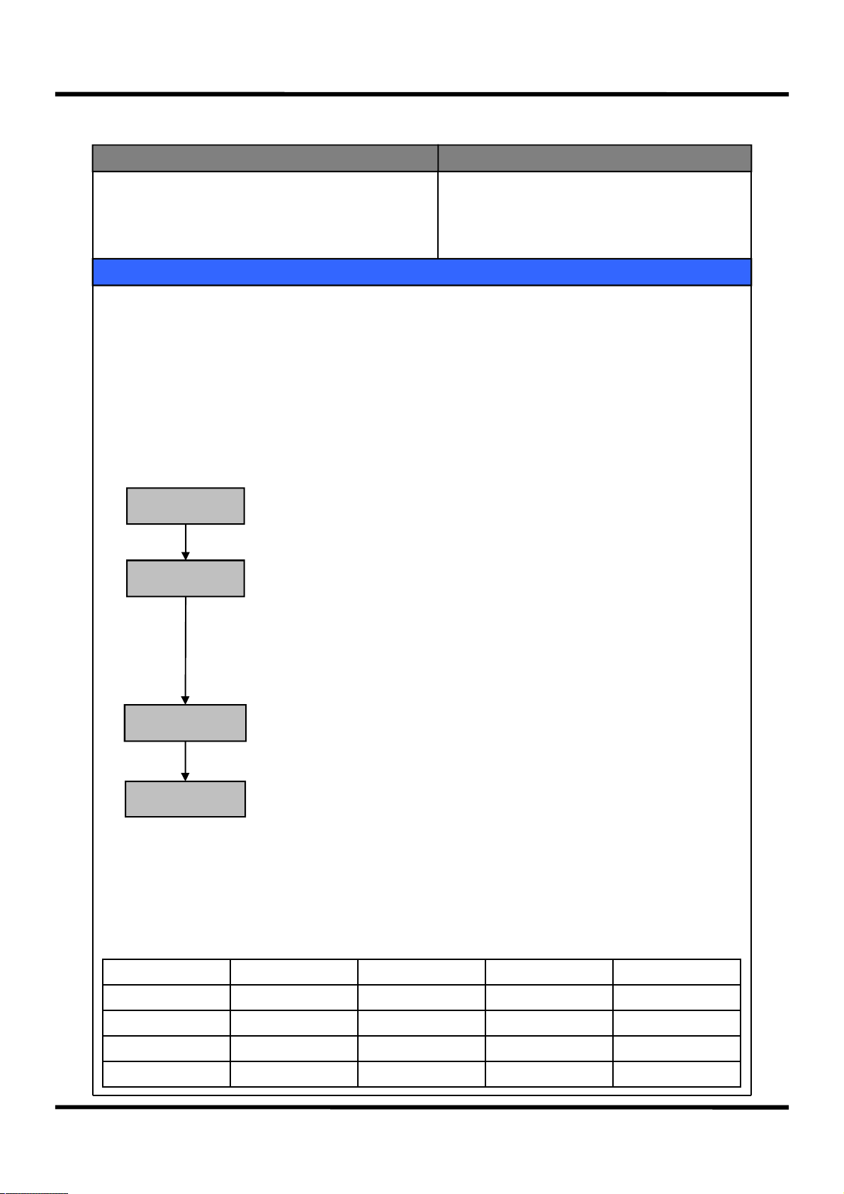
1. Ice-making Flow
시작
START
제빙 MODE
Ice Making MODE
(급수대기상태)
(Water Supply stand by)
Ice Separation
이빙 MODE
MODE
Water Supply
급수 MODE
MODE
Contents
얼음이 만들어짐
▶
Ice is being made
Ice tray is twisted to separate ice cubes
▶
제빙명을 비틀어 얼음을 떨어뜨림
제빙명에 물을 공급함
▶
Water is supplied to ice tray
Control Object
Water Supply
급수확인 MODE
check MODE
Check if water is properly supplied
제대로 급수가 되었는지를 체크함
▶
RETURN
1) Press the Test S/W of the ice machine Ass’y for more than one second, to let the Test Mode proceed
(But 1. Test Mode starts from the Ice Separation mode
2. In Test S/W short circuit Error, the Test will run only once)
2) When the initial power is supplied, the ice machine horizontality balancing is made and the ice-making mode
begins
3) If it is cancelled, during a ice-making flow, after ice-making is paused, the process will start from the ice-
making mode
4) Water-supply hose HTR Control
RT-S Control Time
14℃ or less 30/30(On/Off)
14℃ ~ 28℃ 13/47(On/Off)
28℃ ~ 36℃ 25/35(On/Off)
36℃ or more 40/20(On/Off)
5) Water-supply Ready State
① Condition: When ice full is detected
② Operation: It proceeds only up to the ice-making mode of the ice-making flow (Ice Separation and water-
supply modes paused)
③ Cancellation: Automatically cancelled if normal
27
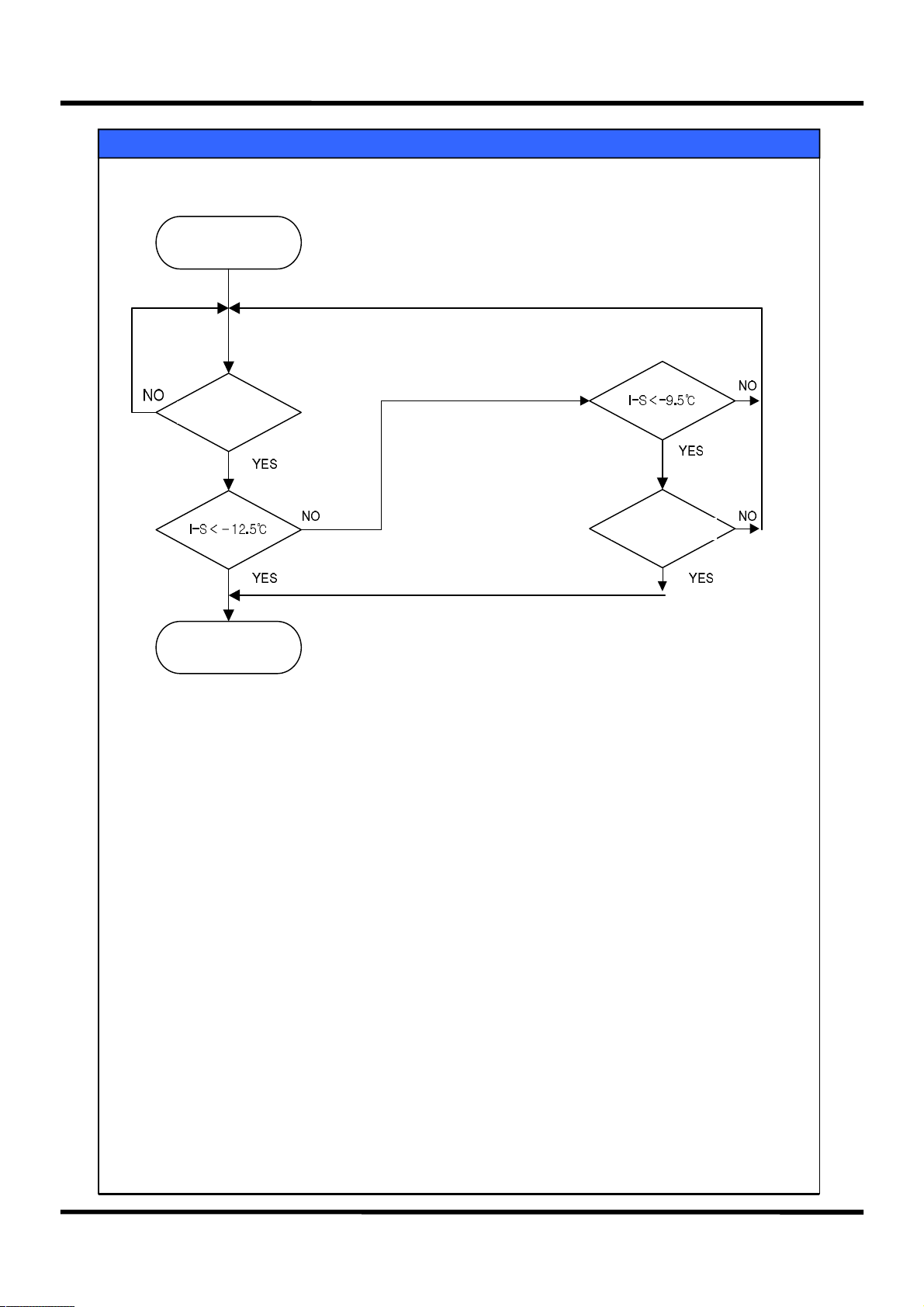
2. Ice-making Mode
START
70 min passed?
Contents
15 min passed?
Ice Separation
MODE
1) If I-S is -12.5℃ or lower after 70 min. lapsing, ice making is finished
2) If I-S is higher than -12.5℃ after 70 min. lapsing but it continuously maintains -9.5℃
or lower for 15 min, ice making is finished
3) If there is an I-Sensor Error, ice making is finished after 4.8hr lapsing
28
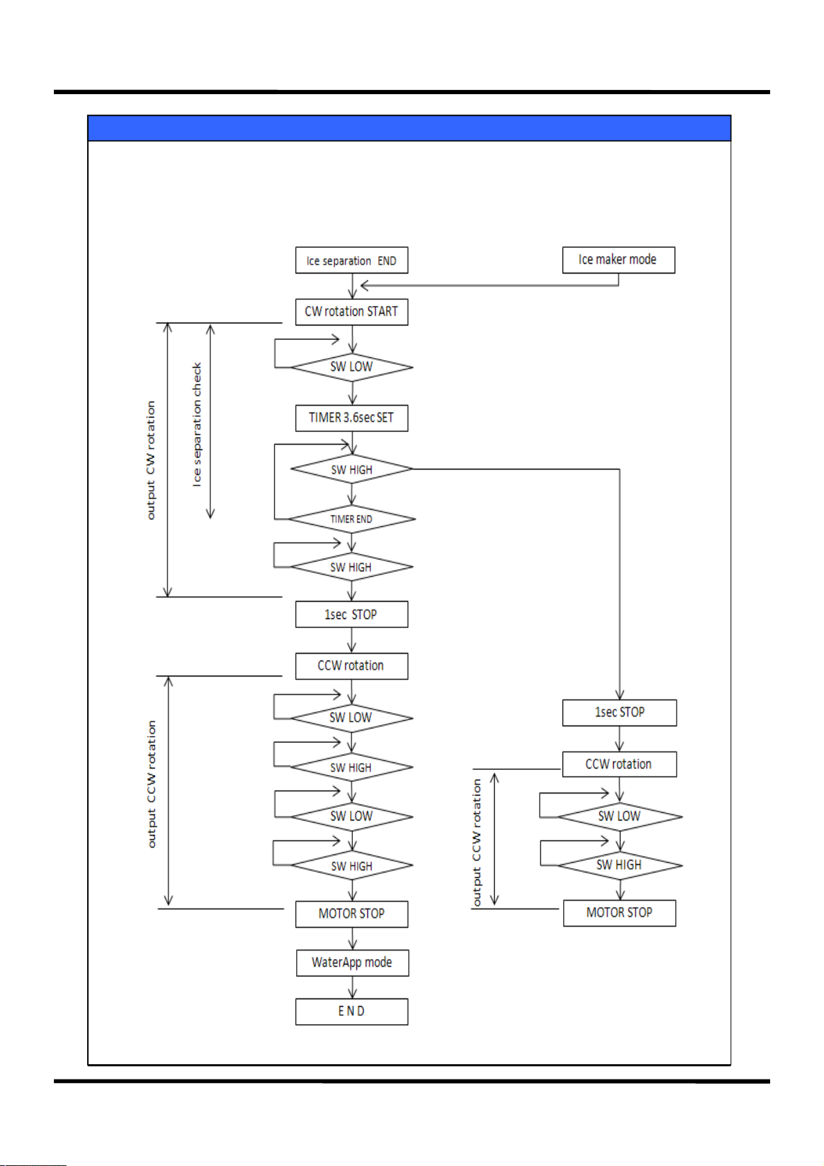
3. Ice Separation Mode
Contents
29
 Loading...