

Page 1

Plasma Display
User Guide
PDS4250
Page 2

Using your Sky+remote control with Sky Plasma Screen
tv
Sets your remote
control to operate the
plasma screen.
mute
Turns the sound from
the plasma screen off
and on.
vol + and -
Changes the plasma
screen volume.
text
Freezes the screen.
Colour keys select
mode options for the
plasma screen.
Red : Sound mode
options.
Green : Picture mode
options.
Yellow : Screen mode
options.
Blue : Screen menu.
Standby
Turns your Sky+box
and your plasma
screen on and off.
i
Displays the input
selection.
ch + and -
Changes the zoom of
the screen.
help
Selects input options
available on the
plasma screen.
Number keys control
input selections and
highlight menu options.
1 : component 1 / 2
input toggle
2 : menu up
3 : AV 1 / 2 / 3 input
toggle
4 : menu left
6 : menu right
7 : DVI input
8 : menu down
9 : PC input
To operate the plasma screen press to start screen options
3
tv
Page 3

Always obey all
safety messages.
•All the safety and
operating
instructions should
be read before the
product is operated.
If anything strange
happens, unplug
this product from
the wall outlet.
•Do not disassemble
or replace any parts
of the monitor.
Refer to a qualified
service personnel
for repair.
For Your Safety
4
W ARNING
You can be killed
or seriously
injured if you do
not follow
instructions.
During a lightning storm, or when left
unattended and unused for long periods
of time, unplug from the wall outlet.
When unplugging your monitor, always
grip plug firmly and pull straight out from
the power socket.
A damaged power cord could cause a fire or an
electric shock.
This product must be properly grounded.
• Improper grounding may cause a malfunction or
an electric shock.
• When proper grounding is not possible, install
circuit breaker.
• Do not ground to gas pipe, water pipe, lightning
rod or telephone line.
During a lightning storm, unplug the
monitor from the wall outlet, and do not
touch the antenna.
Failure to do so could cause a fire or an electric
shock.
Power
When moving your monitor, remove the
power plug, antenna, and cables, and be
sure to move it by at least two people..
Failure to follow this instruction can result in
electric shock or personal injury.
Do not touch the power plug with wet
hands when plugging or unplugging.
It can result in a risk of electric shock.
Page 4

5
Installation
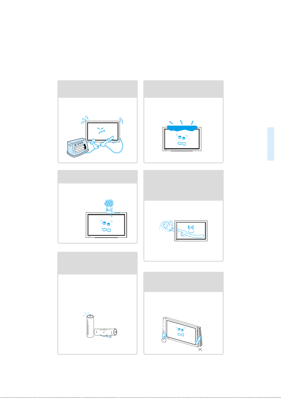
Do not install the product where it will be exposed to
the direct sunlight, and the product should not be
near heat sources such as radiators, stoves, etc.
It may cause malfunction.
Do not install where there is oil, smog,
moist, and dust.
It may cause malfunction.
For proper ventilation, separate the product
from the wall, and keep a distance of more
than 4”.
Due to the increase of temperature inside the
Monitor, it may cause fire.
Do not place the monitor where
ventilation is not ensured.
Due to the increase of temperature inside the
Monitor, it may cause fire.
If you wish to install this product on the
wall or ceiling, refer to the professional.
Failure to do so may cause damage to product
and injury to human.
Do not use this product in the bathroom
or near a shower.
It can result in electric shock or fire.
Do not place this monitor on an unstable
platform (stand, trolley or table)
It may cause the product and platform to overturn,
damaging equipment or causing possible injury.
Always obey all
safety messages.
• All the safety and
operating instructions
should be read before
the product is
operated.
CAUTION
To avoid injury or
damage to this
product (or any
other property)
please read and
follow these
instructions
carefully.
Page 5

6
Using The Monitor
Do not open cover (or back).
High voltage’s are present within the
monitor’s enclosure.
It may cause electric shock.
Never push objects of any kind into
this product through openings at the
back of monitor.
It may cause fire or electric shock.
Do not allow children to play or hang
on the monitor.
These actions may tip it over, causing
personal injury.
Do not place candle or lighted
cigarette on the monitor.
If these fall into the inside of the monitor, it
may cause fire or explosion.
Do not spray water on to the monitor
or wipe with damp cloth.
It may cause electric shock or fire.
Unplug the monitor from the power
socket if smoke or strange smell
occurs. Immediatly refer to a service
technician.
In the case of continuous use, it may cause
fire or electric shock.
Page 6
77
Do not place any object or cover on
the panel.
In an event of improper ventilation, the
panel will be overheat causing fire.
Do not place heavy objects or heat
sources on the power cord.
It may damage the power cord, causing fire
or electric shock.
Do not grip speakers when moving
the panel (if speakers are attached).
When moving the panel, remove the
speakers. Speakers may fall off the panel
due to their weight, causing possible
damage personal injury.
Do not allow a still picture to be
displayed for an extended period, as
this can cause a permanent ghost
image to remain on the plasma
panel. Please refer to the ISM in this
guide.
Examples of still pictures include logos,
video games, computer images, teletext
and images displayed in 4:3 mode.
Warranty does not cover any damage
caused by image retention.
Never place objects filled with liquids
on the monitor.
Spilled liquids may cause electric shock or
fire.
Do not disassemble batteries, and
do not allow children to swallow
them.
Heavy metal may contaminate environment,
and can be harmful or detrimental to human
health. (If your child swallow a battery, go to
hospital and consult with a doctor.)
Page 7
8
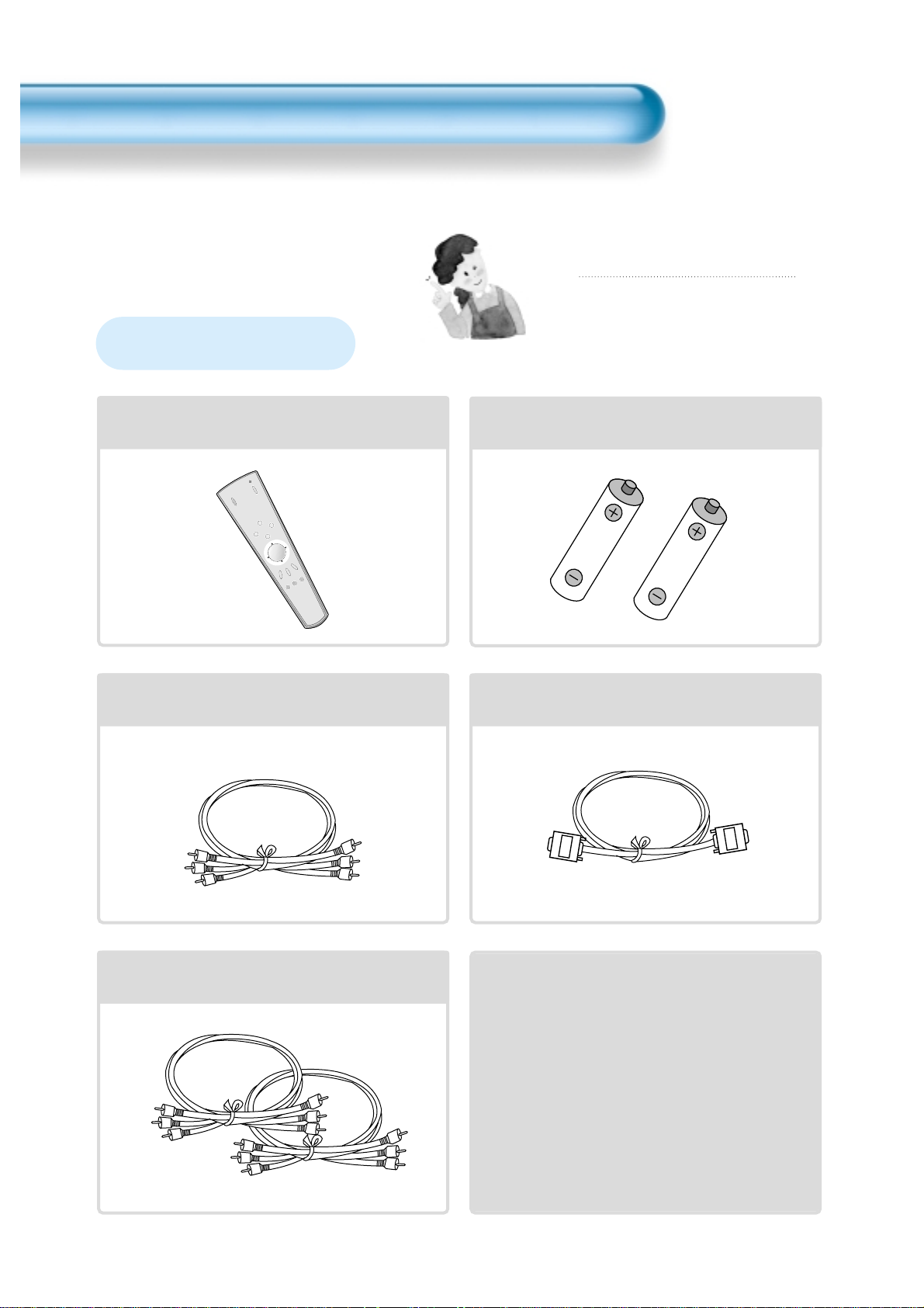
Audio Cable
1UNIT
PC(15pin D-sub) Cable
1 UNIT
A/V Cable
2 UNITS
AC Cable 1 UNIT
Note
Check to be sure that the following items are
packed with your plasma panel.
IN
PU
T
SELEC
T
POW
E
R
D
IS
PLAY
ZO
O
M
-
P
IC
T
U
R
E
M
O
D
E
S
C
R
E
E
N
M
O
D
E
F
R
E
E
Z
E
M
U
T
E
S
O
U
N
D
M
O
D
E
S
L
E
E
P
ZO
O
M
+
M
EN
U
VO
L
V
O
L
Remote Control
1 UNIT
Checking Accessories
Supplied Accessories
Batteries(AAA) 2 UNITS
Page 8
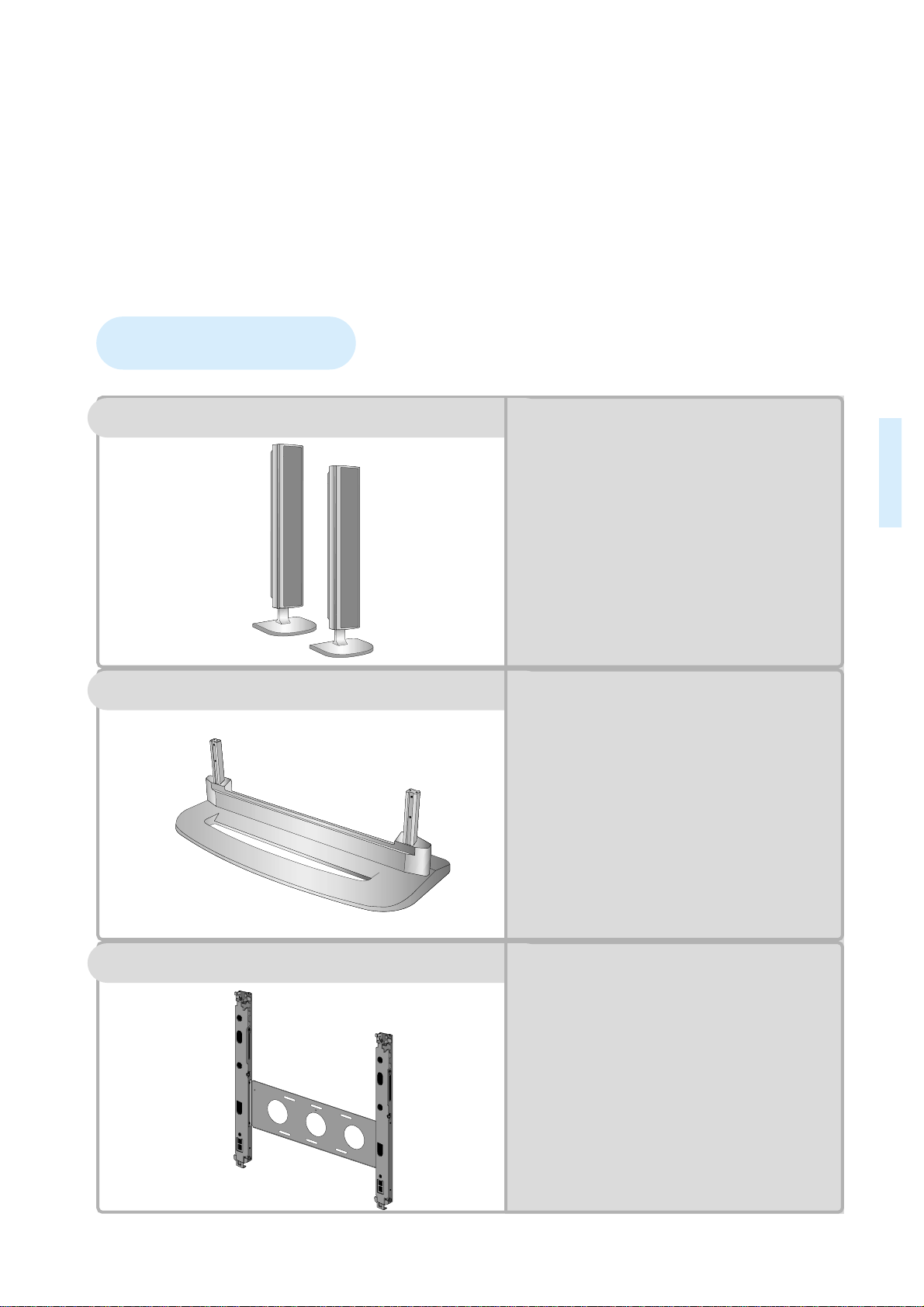
9
Optional Accessories
SP425
-
Speaker Main Unit
Dimension : 100(W) x 628(H) x 88.5(D)mm
-
Including Speaker Stand
Dimension : 210(W) x 704(H) x 210(D)mm
-
Audio Amplifier : 8W + 8W
-
Impedance : 8Ω
-
Weight : 7kg
ST425
-
Dimension : 720(W) x 215(H) x 310(D)mm
-
Weight : 4.5kg
HG425(optional extra)
•
Variable Angles : 0º, 10º, 15º, 20º
Speaker Main Unit
•
Dimension : 601(W) x 592(H) x 35(D)mm
Including Stand
•
Weight : 4.5kg
Wall Mounting Unit
Table Top Stand
Speakers
Page 9

11
12 • Panel Controls
13 • Remote control
PREPARATION
BASICS
14 • Installation Instructions
15 • Connecting Speaker to PDP
CONNECTION
18 • Watching a DVD Image
20 • Watching a VCR Image
22 • Watching a Camcorder/Game Console Image
24 • Connecting PC(15pin D-sub)
26 • Connecting PC(DVI)
28 • PC and DVI Input Resolution Available in PDP
APPLICATION
29 • Selecting Auto Picture Mode
30 •
Customizing Picture
32 •
Adjusting Screen Size
34 • Adjusting Screen Position and Size
36 • Enlarging Screen Size
38 • Watching a Still Image
39 • Adjusting Auto Sound Mode
40 • Customizing Sound Mode
42 • Selecting INPUT SIGNAL
44 • Checking the Current Input Signal
45 •
Selecting MENU Background Screen and Languages
48 • Selecting Image Sticking Minimization
49 • Setting Sleep Timer
MISC.
50 • Before Requesting Service
51 • SPECIFICATIONS
CONTENTS
Page 10
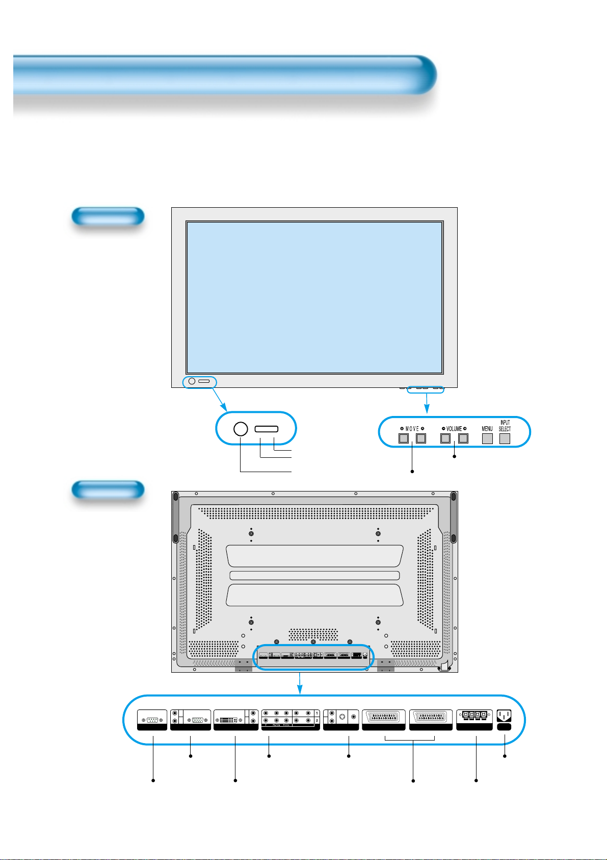
Panel Controls
12
Front Panel, Back Panel, Remote Control
*
Items having same names on the plasma panel and the remote control will function in exactly the
same way.
Front
Rear
RS-232C PORT
AC IN
SPEAKER(8 Ohms)
RL
PC INPUT
L
R
AUDIO
DTV/DVD INPUT
L- AUDIO -R
AV3
L
R
AUDIO
S-VIDEO VIDEO
DVI-INPUT
L
R
AUDIO
AV2 AV1
RS-232C PORT
AC IN
SPEAKER(8 Ohms)
RL
PC INPUT
L
R
AUDIO
DTV/DVD INPUT
L- AUDIO -R
AV3
L
R
AUDIO
S-VIDEO VIDEO
DVI-INPUT
L
R
AUDIO
AV2 AV1
ON/OFF
•
Power control sensor
•
Power Standby: Red - Standby
Green - ON
Power button
DVI-INPUT External Speaker
PC INPUT COMPONENT A/V jacks
(DTV/DVD INPUT jacks)
S-VIDEO, A/V INPUT,
Cable Receiver INPUT
jacks
Power
Select when adjusting volume or
select/adjust “MENU.”
Press when moving “MENU.”
STAND BY/OPERATE
SCART, A/V
INPUT/OUTPUT,
Cable Receiver
INPUT/OUTPUT jacks
Used when
manufacturing (For
manufacturer use only)
Page 11

13
Remote Control
When Using Remote Control:
•
Be sure not to allow the Remote Control to drop or to become wet.
•
Keep it away from hot or moist locations.
Installing the Batteries in your Remote Control:
•
To remove the cover, slide it outwards while pressing it down.
•
Place two batteries in the remote control by properly orienting
them, then close the cover.
INPUT
SELECT
POWER
DISPLAY
ZOOM
-
PICTURE
MODE
SCREEN
MODE
FREEZE
MUTESOUND
MODE
SLEEP
ZOOM+
MENU
VOL VOL
Input Select button
Used to select a desired input.
Every press of the button
cycles through the five
different modes: AV1(SCART)
-->Component 1 --> AV2(SCART)
--> AV3 --> Component 2 -->PC
--> DVI
Used to zoom the screen. To enlarge,
press the (+) button, and to return to
the previous condition, press the (-)
button. (ZOOM Mode: Zoom 0~20)
Select Menu by pressing (Up),
(Down), (Left), (Right) buttons.
Every press of the button cycles through the four different
modes: Normal -->Dynamic --> Cinema --> User etc.
Every press of the button cycles through the five different
modes: Normal -->Movie --> Music -->News -->User etc.
Mutes sound.
Pressing the Power button of the Monitor
allows the Display to be standby. (Red light
is shown in the Remote Control Sensor.)
At this time, if you press the Power button
of the Remote Control, the Display is
turned ON (Green light in the Sensor).
Indicates the current state.
Used to display a desired menu.
Adjusts the volume.
Adjusts the size of the screen
( , 16:9, etc.)
Used to view a still picture during
watching moving images. (Sound
can be heard.)
Each time you press this button, a different
input mode appears.
The sequence is as follows:
15 Min. -->30 Min. -->60 Min. -->90 Min. -->120 Min. -->OFF
After the time is selected, it automatically
becomes stand-by state.
42
30
Menu Select button
36
Screen Select button
29
Sound Mode button
39
Mute button
Aspect Ratio
32
Still
38
Sleep Timer
49
Power button
Display button
44
ZOOM button
Menu button
40
Volume button
30
Note
• Use two “AAA” batteries.
• Be sure to use replacement batteries of the
same type as the original ones.
• The life of a battery depends on how much
the remote control has been used.
*
The number in
()
indicates the page in which
the function of each button is explained in detail.
Page 12

14
Installation Instructions
When Using the Stand
M5 SCREWS
*
When installing PDP Main Unit, be sure it is done by more than 2 professionals.
*
For detailed installation information, refer to the User’s Manual, “STAND”.
.
Open and take out the stand from the
box and remove wrapper.
.
Slide the stand under the plasma display
like the picture below.
.
Use the enclosed 2 M5 screws to
secure the assembled stand.
(Picture of a properly installed stand
and display)
Page 13

15
.
Take the speaker wire(2) and use the red cord to connect to and fro (+) inputs,
and use the black cord to connect to and fro (-) inputs.
Connecting the Speaker to the PDP
.
Please, use a coin to
loosen the special
screws.
Stand
Speaker
.
To avoid loose fitting, please be sure that screws are secured tightly.
Otherwise, vibrating or distorted sounds may be produced.
Note
.
Please be sure to connect red wire with (+) and black with (-); otherwise, speakers will not
produce clear sounds.
.
Please retain any unused accessories.
.
Connecting Clamp Wires:
- Used keep the speaker wire neat (When the speakers are cinnected to the side of main unit).
Note
Page 14
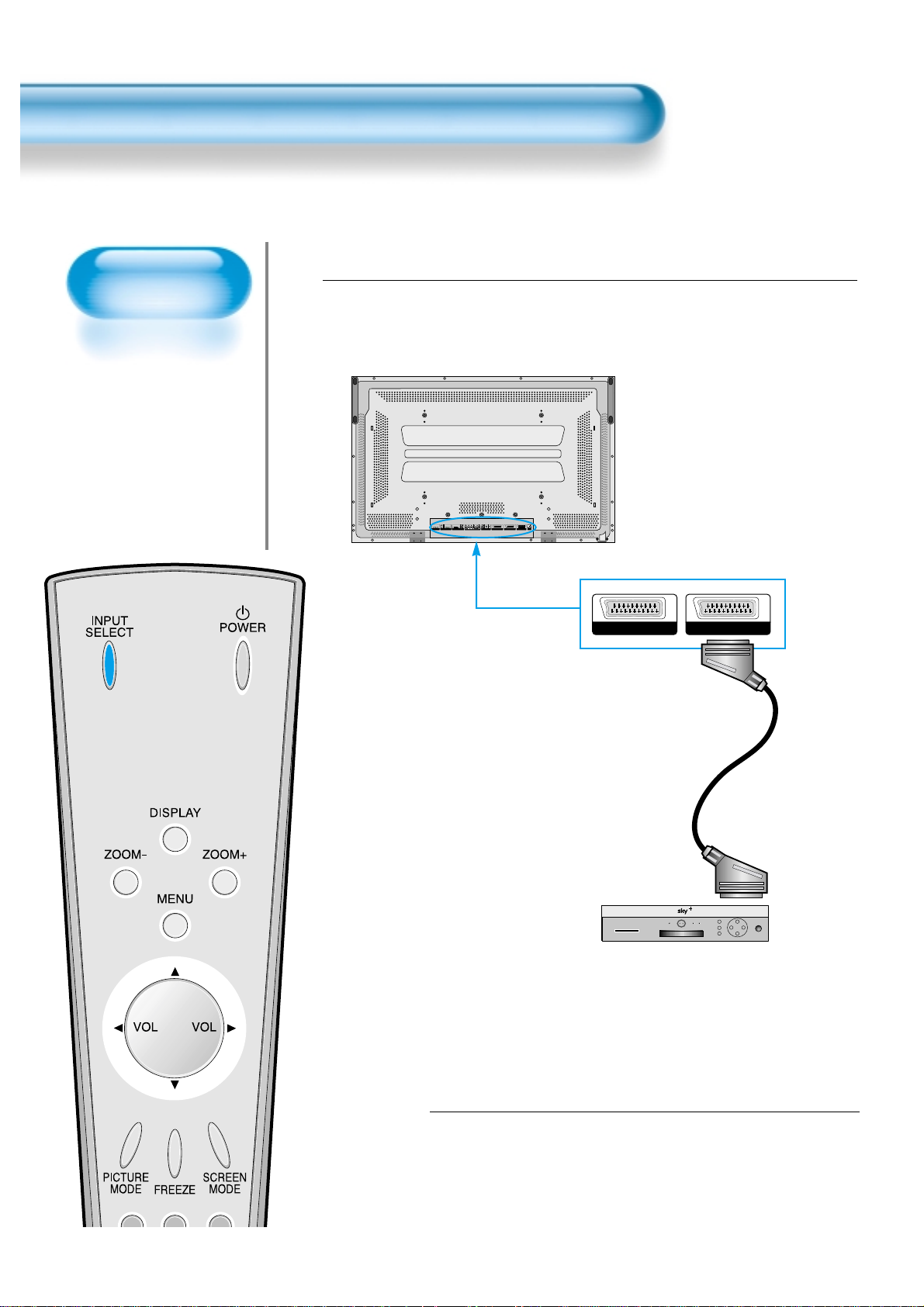
Watching Satellite
Broadcasts
• To watch satellite
broadcasting,
subscribe to SKY
Digital then connect
the set-top box to
the PDP as shown
below.
Watching Satellite Broadcasts
16
Press the Power Buttons
• T urn the PDP and the Receiver ON.
2
Connect a Satellite Broadcasting Receiver to
the PDP.
• Prepare the A/V SCAR Tcable.
• Connect the receiver(Output) to PDP Input(AV1) as shown below .
1
Satellite Broadcasting Receiver
Video/Audio
R
R
R
AUDIO
AUDIO
AUDIO
L
L
L
S-VIDEO VIDEO
RL
L- AUDIO -R
RS-232C PORT
PC INPUT
DVI-INPUT
DTV/DVD INPUT
SPEAKER(8 Ohms)
AV3
AV2 AV1
AC IN
AV1AV2
Page 15
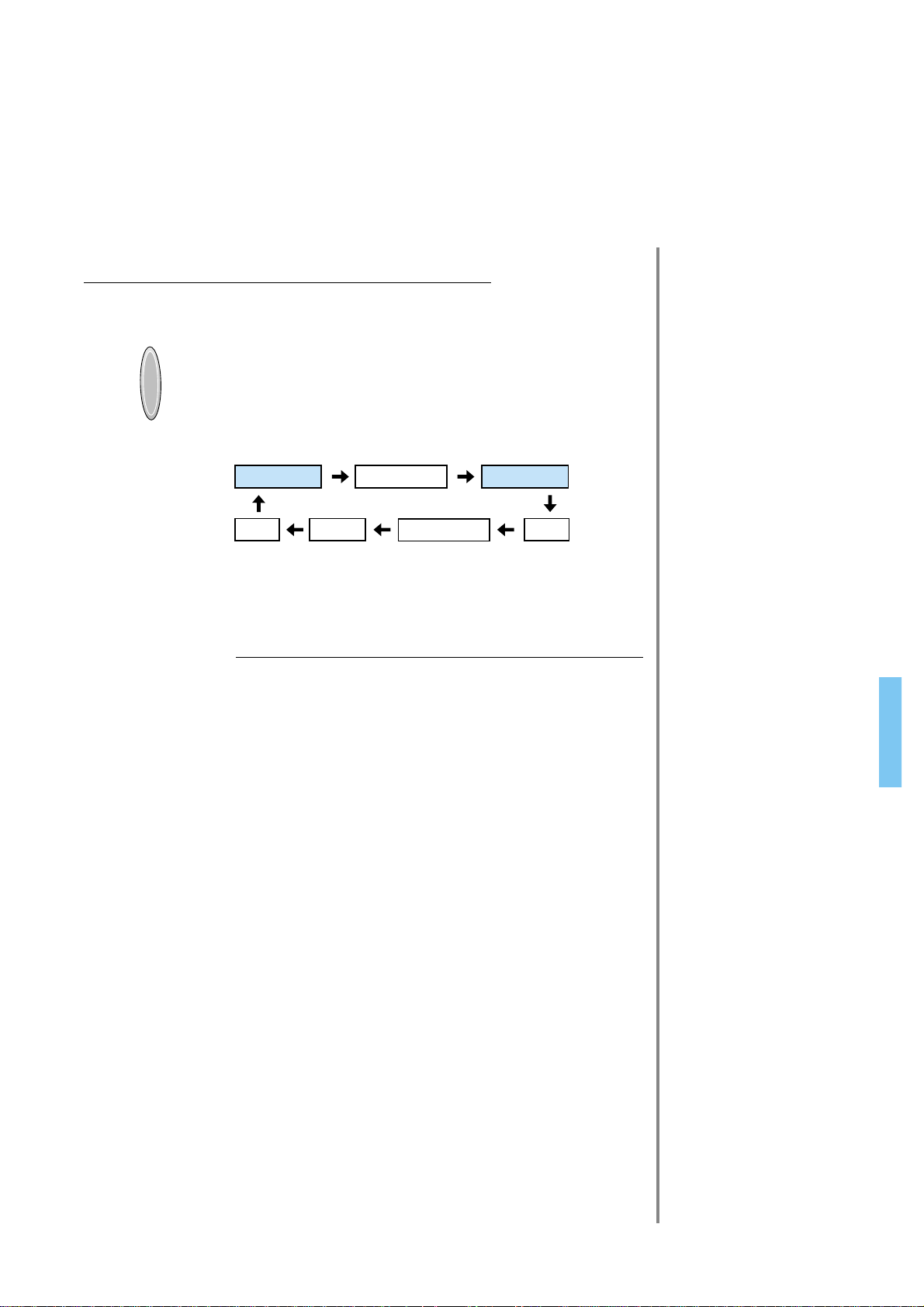
17
Input Select
INPUT
SELECT
• Select [
AV1(SCART) or AV2(SCART)
] by
pressing the INPUT SELECT button of
the Remote Control or the PDP unit.
• Each time you press the INPUT SELECT
button, different input mode appear. The
sequence is as follows:
Select a Desired Channel and Function
• Select a desired channel and function by
using the Remote Control of the Satellite
Broadcasting Receiver.
3
4
NOTES:
1)
Picture quality of the Digital Satellite broadcasts is SD grade,
and its aspect ratio is 16:9.
2) When signal cables are connected simultaneously,
AV1(SCART) has priority over other signals.
Activating the device connected to AV1(SCART) will switch
input mode to AV1(SCART) for all input.
AV 1(SCART) AV 2(SCART)
PCDVI AV3
Component 1
Component 2
Page 16

Watching a DVD
Image
• Component Input is
set to 480i and 480p
mode.
• Connect the cable
from the DVD Video
Output (Y, Pb/Cb,
Pr/Cr) to the
Component Input at
the back of PDP, and
connect the cable
from DVD Audio
output (Left, Right)
to the Audio Input at
the back of PDP.
Watching a DVD Image
18
Press the Power Buttons
• T urn the PDP and the DVD ON.
2
Connect a DVD Player to the PDP.
• Prepare the AV or SCART cable.
• Connect the DVD(Output) to the PDP(Component or Video Input) as shown below .
• When connecting to an external A V source, match the colors.
1
DTV/DVD INPUT
L- AUDIO -R
AV3
L
R
AUDIO
S-VIDEO VIDEO
AV2 AV1
RS-232C PORT
AC IN
SPEAKER(8 Ohms)
RL
PC INPUT
L
R
AUDIO
DTV/DVD INPUT
L- AUDIO -R
AV3
L
R
AUDIO
S-VIDEO VIDEO
DVI-INPUT
L
R
AUDIO
AV2 AV1
Video
DVD DVD DVD
Video/
Audio
Video/
Audio
S-
Video
Audio
Page 17

19
Input Select
INPUT
SELECT
• Select [Component 1, Component 2,
AV1(SCART), AV2(SCART), or AV3] by
pressing the INPUT SELECT button of the
Remote Control or the PDP unit.
• Each time you press the INPUT SELECT
button, a different input mode appears. The
sequence is as follows:
Select a Desired Title and Function
• Select a desired title and function by
using the Remote Control of the DVD.
3
4
NOTES:
1) Y/Cb/Cr, which stands for DVD Player’s Output Terminal, can
also be written as Y/B-Y/R-Y, Y/Pb/Pr depending on the kinds
of DVD devices.
2) The way of connecting the DVD to the PDP is as follows:
Y <---> Y Cb <---> Pb, B-Y, Cr <---> Pr, R-Y
3) The DVD output can be made by Video, S-Video and/or
Component Video depending on the DVD devices. There are
various output modes, so be sure to check when to purchase it.
4) In AV3 mode, when connecting S-Video and Video
simultaneously, only S-Video will be displayed on the screen.
AV 1(SCART) AV 2(SCART)
PCDVI
Component 1
Component 2
AV3
Page 18

Watching a
VCR Image
• Video can use either
the Video terminal or
the S-video terminal.
Watching a VCR Image
20
Press the Power Buttons
• T urn the PDP and the VCR ON.
2
Connect a VCR to the PDP.
• Prepare the AV or SCART cable.
• Connect the Video(Output) to PDP(Video Input) as shown below.
1
AV3
L
R
AUDIO
S-VIDEO VIDEO
AV2 AV1
RS-232C PORT
AC IN
SPEAKER(8 Ohms)
RL
PC INPUT
L
R
AUDIO
DTV/DVD INPUT
L- AUDIO -R
AV3
L
R
AUDIO
S-VIDEO VIDEO
DVI-INPUT
L
R
AUDIO
AV2 AV1
S-Video
Video/
Audio
VCR
Video/Audio
Page 19

21
Input Select
INPUT
SELECT
• Select [AV1(SCART), AV2(SCART) or
AV3] by pressing the INPUT SELECT
button of Remote Control or PDP unit.
• Each time you press the INPUT
SELECT button, a different input mode
appears. The sequence is as follows:
Select a Desired Title and Function
• Select a desired title and function by
using the Remote Control of the
VCR.
3
4
NOTES:
1) When connecting a Video, the S-Video terminal provides a
better image than the Video terminal.
2) When connecting to the Video terminal, connect 3 color AV
cables (video, left audio, right audio) to the PDP; for the SVideo terminal, connect the Audio terminal (Left, Right) in the
same way, and connect the Video terminal by the S-Video
cable (sold separately).
3) When connecting the Video terminal and the S-Video
simultaneously, the S-Video terminal is selected. This can be
checked by the [Display] button of the Remote Control.
AV 1(SCART) AV 2(SCART)
PCDVI AV3
Component 1
Component 2
Page 20

Watching a
Camcorder/Game
Console Image
• Enjoy images
recorded by
camcorder or the
game console after
connecting to the
PDP.
W atching a Camcorder/Game Console Image
22
Press the Power Buttons
• Turn the PDP and the
Camcorder/Game Console ON.
2
Connect a Camcorder/Game Console to the
PDP.
• Prepare the AV cable.
• Connect the Video(Output) to the PDP(Video Input) as shown below.
• When connecting to an external AV source, match the colors.
1
AV3
L
R
AUDIO
S-VIDEO VIDEO
RS-232C PORT
AC IN
SPEAKER(8 Ohms)
RL
PC INPUT
L
R
AUDIO
DTV/DVD INPUT
L- AUDIO -R
AV3
L
R
AUDIO
S-VIDEO VIDEO
DVI-INPUT
L
R
AUDIO
AV2 AV1
S-Video Video/Audio
Game Console/Camcorder
Page 21

23
Input Select
INPUT
SELECT
• Select [A V3(S-Video/Video] by
pressing the INPUT SELECT button
of the Remote Control or the PDP
unit.
• Each time you press the INPUT
SELECT button, a different input
mode appears. The sequence is as
follows:
• Select the function by using the
Remote Control of Camcorder or
Game Console.
Select Function
3
4
NOTES:
1) When connecting a Video, the S-Video terminal provides a
better image than the Video terminal.
2) When connecting to the Video terminal, connect 3 color AV
cables (video, left audio, right audio) to the PDP; for the SVideo terminal, connect the Audio terminal (Left, Right) in the
same way, and connect the Video terminal by S-Video
cable(sold separately).
3) When connecting a component, please refer to “Watching a
DVD Image” on page 20-21.
AV 1(SCART) AV 2(SCART)
PCDVI
AV3(S-Video/Video)
Component 1
Component 2
Page 22

Connecting PC
• PLASMA supports
resolution of VGA,
SVGA, XGA, SXGA,
UXGA.
• Before connecting a
PC to the PDP, be
sure to adjust the
resolution of PC.
Connecting PC(15pin D-sub)
24
Connect the PC to the PDP.
• Prepare the PC cable (D-sub 15pin) and
the PC audio cable(Sold seperately).
• Connect the PC(Output) to the
PDP(Input) as shown below.
2
Before connecting to the PDP, set the
resolution of the PC.
• Go to SETUP-CONTROL PANEL-DISPLAY PROPERTIES in Window
Screen.
• Choose the SETTINGS tab in the DISPLAY Menu.
• In the SETTINGS Menu, select 640x480 or 800x600.
1
PC INPUT
L
R
AUDIO
RS-232C PORT
AC IN
SPEAKER(8 Ohms)
RL
PC INPUT
L
R
AUDIO
DTV/DVD INPUT
L- AUDIO -R
AV3
L
R
AUDIO
S-VIDEO VIDEO
DVI-INPUT
L
R
AUDIO
AV2 AV1
15 PIN D-sub
PC
Audio
Page 23

25
Input Select
INPUT
SELECT
• Select [PC] by pressing the INPUT
SELECT button of the Remote Control or
PDP unit.
• Each time you press the INPUT SELECT
button, a different input mode appears. The
sequence is as follows:
Enjoy Dynamic Ultra Screen Monitor by
Using PC’s Keyboard or Mouse.
4
5
Press the Power button.
• Turn on the PDP and the PC.
3
NOTES:
1) The resolution of the PC monitor is best at 640 x 480 (VGA).
2) If there is a [Vertical Frequency]setting menu in the [Display]
Menu of the PC, adjust the frequency to 60Hz.
3) If the PC resolution is too high, it may be hard to read letters.
Select a suitable resolution.
AV 1(SCART) AV 2(SCART)
PCDVI AV3
Component 1
Component 2
Page 24

Connecting PC
• PLASMA supports
resolution of VGA,
SVGA, XGA, SXGA,
UXGA.
• Before connecting a
PC to the PDP, be
sure to adjust the
resolution of PC.
• This product is not
supported by Plug
and Play, so select
Standard Monitor
when setting PC
monitor.
Connecting PC(DVI)
26
Connect the PC to the PDP.
• Prepare the DVI cable and the PC audio
cable(Sold seperately).
• Connect the PC(Output) to the
PDP(Input) as shown below.
2
Before connecting to the PDP, set the
resolution of the PC.
• Go to SETUP-CONTROL PANEL-DISPLAY PROPERTIES in Window
Screen.
• Choose the SETTINGS tab in the DISPLAY Menu.
• In the SETTINGS Menu, select 640x480 or 800x600.
1
DVI-INPUT
L
R
AUDIO
RS-232C PORT
AC IN
SPEAKER(8 Ohms)
RL
PC INPUT
L
R
AUDIO
DTV/DVD INPUT
L- AUDIO -R
AV3
L
R
AUDIO
S-VIDEO VIDEO
DVI-INPUT
L
R
AUDIO
AV2 AV1
DVI
PC
Audio
Page 25

27
Input Select
INPUT
SELECT
• Select [DVI] by pressing the INPUT
SELECT button of the Remote Control or
PDP unit.
• Each time you press the INPUT SELECT
button, a different input mode appears. The
sequence is as follows:
Enjoy Dynamic Ultra Screen Monitor by
Using PC’s Keyboard or Mouse.
4
5
Press the Power button.
• Turn on the PDP and the PC.
3
NOTES:
1) The resolution of the PC monitor is best at 640 x 480 (VGA).
2) If there is a [Vertical Frequency]setting menu in the [Display]
Menu of the PC, adjust the frequency to 60Hz.
3) If the PC resolution is too high, it may be hard to read letters.
Select a suitable resolution.
4) DVI input port receive only Digital Signal.
5) Depending on the graphic card when plug and unplug the DVI
connection, the screen may not display correctly.
Restart the computer, if this happen.
AV 1(SCART) AV 2(SCART)
PCDVI AV3
Component 1
Component 2
Page 26

PC and DVI Input Resolution Available in PDP
28
• According to the kind of graphic card, there is no picture of pc input and some problems like line noises
can happen in picture. If these problems happen, ask to a graphic card company.
Resolution
Horizontal Frequency(KHz) Vertical Frequency(Hz) Remark DVI PC
31.469
37.861
24.823
30.48
31.469
37.861
31.469
35
37.861
37.5
39.375
43.269
31.47
31.469
37.927
31.54
15.63
35.156
35.16
37.879
48.077
46.875
53.674
49.726
48.193(48.077)
48.363
53.95
56.476
60.241
60.023
68.677
80.66
70.84
54
63.851
67.5
77.094
61.796
71.713
45
60
75
85.938
46.433
63.981
70.66
74.88
78.125
78.855
79.976
81.13
91.416
62.5
75
81.25
87.5
93.75
100
640x350
640x400
640x480
720x400
720x480
720x576
800x600
832x624
1024x768
1152x864
1152x900
1280x720
1280x960
1280x1024
1600x1200
70.1
85.1
56.4
60.0
70.1
85.1
59.9
66.7
72.8
75.0
75.0
85.0
60.1
70.1
85.1
60.0
25.0
56.3
57.2
60.3
72.2
75.0
85.1
74.0
59.3(59.8)
60.0
66.1
70.1
74.9(74.6)
75.0
85.0
100.0
84.0
60.0
70.0
75.0
85.0
66.0
76.0
60.0
60.0
75.0
85.0
43.4
60.0
66.5
70.0
72.0
74.0
75.0
76.1
85.0
48.0
60.0
65.0
70.0
75.0
80.0
O
O
O
O
O
O
O
O
O
O
O
O
O
O
O
O
O
O
O
O
O
O
O
O
O
O
O
O
O
O
O
O
O
O
O
O
O
O
O
O
O
O
O
O
O
O
O
O
O
O
O
O
O
O
O
O
O
O
O
O
O
O
O
O
O
O
O
O
O
O
O
O
O
O
O
O
O
O
O
O
O
IBM
VESA
NEC
PGA
IBM (DOS)
VESA
DOS
Macintosh
VESA
VESA
IBM
VESA
VGA
IBM
VESA
480P
PAL
VESA
VESA
VESA
VESA
VESA
VESA
Macintosh
Macintosh (OAK)
VESA
XGA
HP & VESA
Macintosh
VESA
VESA
Fujitsu
SUN
VAX
VESA
VESA
VESA
SUN
SUN
720P
VESA
VESA
VESA
VESA
VESA
VAX
NEC
HP & HITA
Sony & NEC
VESA
SUN
VESA
VESA
VESA
VESA
VESA
VESA
VESA
Page 27

Selecting Picture
Mode
• Select the Picture modes
that are appropriately set
depending on the kinds
of pictures, and enjoy
them.
Selecting Picture Mode
PICTURE
MODE
• Press the [PICTURE MODE] on the
Remote Control.
• Pressing the [PICTURE MODE] first time
will display the current PICTURE MODE.
Each Press of the Button Will Select
One of Four Picture Modes.
• Each time you press the button, a
different Picture mode appears. The
sequence used is as follows:
* Normal : For a highly defined image in a normally bright
room
* Dynamic: For a clear-cut image emphasizing high contrast
for sports viewing
* Cinema: For a movie
* User: Allows the user to customize settings as desired.
Menu on the Screen Will Disappear .
• After selecting a desired Picture mode, the
menu on the screen will disappear.
• Normal, Dynamic, and Cinema Modes are
factory preset values.
If you want to customize the Picture modes,
refer to the following page.
3
1
2
Selecting Picture Mode
29
NOTES:
1) Normal, Dynamic, and Cinema Modes are factory preset values.
2) When adjusting sub-menus while you are in Normal, Dynamic,
and Cinema Modes, the Picture Mode will be automatically
converted to User Mode, and the adjustments will be made.
3) Pressing of the [INITIALISATION] button in the [Utility] Menu will
allow for the Brightness, Contrast, etc. to return to the factory
preset values.
4) The SHARP Menu adjusts the picture sharpness.
5) Adjusting the Color Temperature makes the mood warm or cold.
PICTURE
MODE
INPUT
SELECT
POWER
DISPLAY
ZOOM
-
PICTURE
MODE
SCREEN
MODE
FREEZE
MUTESOUND
MODE
SLEEP
ZOOM+
MENU
VOL VOL
Normal Dynamic
Cinema User
Page 28

Customizing
Picture
• You can adjust the
color tone and
brightness to your
preference.
Customizing Picture
30
INPUT
SELECT
POWER
DISPLAY
ZOOM
-
PICTURE
MODE
SCREEN
MODE
FREEZE
MUTESOUND
MODE
SLEEP
ZOOM+
MENU
VOL VOL
Press the / Button.
• After selecting [Picture] by the / buttons, press the
button that will display the following.
Select the Custom Mode.
• Select [User] by the / buttons.
3
Press the MENU Button.
• The MENU shown below will display on the screen.
1
2
MENU
Picture
Sound
Screen
Utility
Input
Mode
Brightness
Contrast
Color
Sharpness
Color Temp.
Normal
Normal
Move
Picture
VOLVOL
Sound
Screen
Utility
Input
Mode
Brightness
Contrast
Color
Sharpness
Color Temp.
Move
Previous
Select
Normal
Normal
Previous
Adjust
Picture
Sound
VOLVOL
Screen
Utility
Input
Mode
Brightness
Contrast
Color
Sharpness
Color Temp.
Move
User
Normal
Previous
Adjust
Page 29

Select User Mode Adjustments
Picture Condition Adjustments
• Press the / buttons to adjust the picture at your
preference.
4
5
31
• While you are in [Picture Mode – User], press the / buttons to
select a specific adjustment item.
NOTES:
1) While you are in the PC or DVI INPUT mode, you can only
adjust brightness, contrast, sharpness and color temperature.
2) When you adjust Brightness, Contrast, Color, Tint in DTV
mode or adjust Brightness, Contrast in PC or DVI mode, the
picture is adjusted finely.
3) The adjusted values are memorized in each mode separately.
4) The Tint control is used only when the input signal is NTSC.
If input signal is NTSC, Tint control is displayed in picture
menu.
VOLVOL
VOLVOL
Picture
Sound
Screen
Utility
Input
Mode
Brightness
Contrast
Color
Sharpness
Color Temp.
Move
User
Normal
Previous
Adjust
Picture
Sound
Screen
Utility
Input
Mode
Brightness
Contrast
Color
Sharpness
Color Temp.
User
Normal
Move
Previous
Adjust
Page 30

Adjusting
Screen Size
• You can adjust
screen size or
aspect ratio as
desired.
Adjusting Screen Size
32
INPUT
SELECT
POWER
DISPLAY
ZOOM
-
PICTURE
MODE
SCREEN
MODE
FREEZE
MUTESOUND
MODE
SLEEP
ZOOM+
MENU
VOL VOL
Press the SCREEN MODE Button.
• Each time you press the SCREEN MODE button on the
Remote Control, a different SCREEN MODE appears. The
sequence used is as follows:
• The MENU shown below will display on the screen.
1
SCREEN
MODE
Enlarge LBS
Auto
16:9
Panorama
Enlarge LB
NOTES:
1) When the INPUT SIGNAL is DTV [in COMPONENT 1 or
COMPONENT 2], only the aspect ratios of 16:9 and
4:3(Auto) will be applied by Input signal.
Etc) If input signal is 16:9, PDP displays in 16:9 mode.
2) The digital broadcasting (480p or above) is fixed at the
aspect ratio of 16:9.
3) Displaying a picture in 4:3 Screen Size for a long time may
cause phosphor of the PDP to be burned. So avoid
displaying a picture in 4:3 Screen Size for a long time.
4) 16:9 : Theater-like 16:9 picture formats.
Panorama : 16:9 picture formats with panorama effect
Auto : Displays pictures of original picture size.
Enlarge LB : Enlarges the screen as to fill the black part of
up and down.
Enlarge LBS: Enlarges the screen, and shifts up as to see
the subtitles in case you are watching video
with subtitles.
Page 31

33
Press the MENU Button.
• Press the [MENU] button on the Remote Control.
Select “Screen”.
• Press the Channel / buttons to select “Screen.”
Select the Screen Size.
• Press the V olume / buttons to select “Screen Size”.
3
1
2
Adjusting from
MENU Screen
• Available Screen Mode
Input Available Mode
PC,DVI None
Component 16:9, Auto
(480p or above)
AV1, AV2 16:9, Panorama
SVHS1 Auto
AV3 Enlarge LB
Component Enlarge LBS
(480i)
MENU
Picture
Sound
Screen
Utility
Input
Mode
Brightness
Contrast
Color
Sharpness
Color Temp.
Move
Normal
Normal
Previous
Select
VOLVOL
Picture
Sound
VOLVOL
Screen
Utility
Input
Picture
Sound
Screen
Utility
Input
Mode Enlarge LB
Mode Auto
Move
Previous
Select
Move
Previous
Adjust
Page 32

Adjusting Screen
Position and Size
• You can adjust the
screen position and
size as desired.
• This function is only
used when adjusting
the screen position
and size on the PDP
monitor by using the
PC or DVI input
signal.
INPUT
SELECT
POWER
DISPLAY
ZOOM
-
PICTURE
MODE
SCREEN
MODE
FREEZE
ZOOM+
MENU
VOL VOL
Press the MENU Button.
• The MENU screen as shown below will appear.
Press the / Button.
• Press the / buttons to select ‘Screen’.
1
2
34
Adjusting Screen Position and Size
MENU
VOLVOL
Picture
Sound
Screen
Utility
Input
Mode
Brightness
Contrast
Sharpness
Color Temp.
Move
Normal
Normal
Previous
Select
Picture
Sound
Screen
Utility
Input
H. Size
V. Size
H. Position
V. Position
Phase
Frequency
Move
Previous
Select
Page 33

35
Press the Volume / Buttons.
• Press the V olume / buttons to select “Screen”.
• While you are in ‘Screen’ mode, press the
or button to select a desired item, and
then, adjust the value by pressing the or .
3
NOTES:
1) Horizontal/Vertical size and position values can be adjusted only in
the [PC] or [DVI] input mode.
2) H. Size: As the value increases, the screen width increases
3) V. Size: As the value increases, the screen height increases.
4) H. Position: Increasing value moves screen to the right.
As the value increases, the screen moves to the right.
5) V. Position: Increasing value moves screen up.
As the value increases, the screen moves up.
6) Phase: When there are zitter or blurring in image, adjust this value.
7) Frequency: When there are zitter or blurring in image, adjust this
value.
VOLVOL
Picture
Sound
Screen
Utility
Input
H. Size
V. Size
H. Position
V. Position
Phase
Frequency
Move
Previous
Adjust
Page 34

INPUT
SELECT
POWER
DISPLAY
ZOOM
-
PICTURE
MODE
SCREEN
MODE
FREEZE
MUTESOUND
MODE
SLEEP
ZOOM+
MENU
VOL VOL
Press the ‘ZOOM+’ Button.
• Press the ‘ZOOM+’ button to show currently selected
screen size.
• Each time you press the ‘ZOOM+’ button, the screen size
will increase stepwise in 0 ~ 20 scale.
• To reduce the screen size, press the [ZOOM-] button.
1
36
Enlarging
Screen Size
• You can view
enlarged size of the
screen with this
function
Enlarging Screen Size
Zoom Level 0
ZOOM+
Zoom Level 0
Zoom Level 5
Zoom Level 10
Zoom Level 15
Zoom Level 20
Page 35

Move the Screen Position.
• While you are in the ‘Zoom’ mode, press the / ,
/ buttons to move screen stepwise up/down,
left/right, respectively .
2
37
NOTES:
1) When the screen is enlarged, the pixel of the screen can
become thick and dim.
2) When only subtitle of zoom level remains, you can scroll the
image.
If subtitle of zoom level disappears, press zoom key, and
scroll the image.
3) You can enlarge the screen on freeze mode.
Zoom Level 6
VOLVOL
Page 36

INPUT
SELECT
POWER
DISPLAY
ZOOM
-
PICTURE
MODE
SCREEN
MODE
FREEZE
MUTESOUND
MODE
SLEEP
ZOOM+
MENU
VOL VOL
Press the ‘FREEZE’ Button.
• If you wish to freeze a picture, press the ‘FREEZE’ button.
Y ou can still hear the sound.
• Press FREEZE button to cancel the ‘FREEZE’ function.
• To view the enlarged images, press the [ZOOM+] button.
1
FREEZE
38
Watching a
Still Image
• You can view still
images temporarily
with this function.
However, displaying
the same images
such as still images
for a long time may
cause image
sticking.
Watching a Still Image
NOTES:
1) Displaying the same images such as still images for a long time
may cause image sticking.(after-image lagging)
2) In this case, such “image sticking” may become less noticeable if
moving images are later displayed for a long time.
3) However, an image sticking may become a permanent one,
damaging the Plasma Display; therefore, avoid displaying the same
images for a long time.
4) Use the function [ISM], while displaying still images for a long period
of time to minimize this effect.
Freeze
Zoom Level 7
Move the Screen Position.
• While you are in ‘FREEZE’ mode, press the / ,
/ buttons to move screen stepwise up/down and
left/right.
2
VOLVOL
Page 37

Adjusting Auto
Sound Mode
• Enjoy various sound
modes by selecting
your favorite Sound
Mode depending on
the kinds of moving
pictures.
Adjusting Auto Sound Mode
39
INPUT
SELECT
POWER
DISPLAY
ZOOM
-
PICTURE
MODE
SCREEN
MODE
FREEZE
MUTESOUND
MODE
SLEEP
ZOOM+
MENU
VOL VOL
Select SOUND Mode.
SOUND
MODE
• Press the [SOUND MODE] on the
Remote Control.
• Press of the [SOUND MODE] for the
first time will display the current
SOUND MODE.
Every Press of the Button Changes Modes.
SOUND
MODE
• Each time you press the button, a
different sound mode appears.
The sequence used is as follows:
* Normal : Suitable for watching any motion picture
* Movie : Select this mode to simulate being at a movie theater
* Music : Ideal for listening to music
* News : Allows human voice to be heard more clearly
* User : Allows the user to adjust as desired.
MENU will Disappear .
• After selecting a desired SOUND Mode,
on-screen menu will disappear in about
2~3 seconds.
• Normal, Movie, Music, News Modes are
factory preset values.
If you want to customize the sound modes
at your preference, refer to the following
page.
3
1
2
Normal Movie
Music UserNews
Page 38

Customizing
Sound Mode
• This feature allows
the user at adjust at
his preference.
Customizing Sound Mode
40
Press the / Button.
• Select [SOUND] by the / buttons, then press the
button to display the following.
Select SOUND BALANCE.
• Select [SOUND BALANCE] by the / buttons, then
adjust it.
• Sound balance is best at ‘0’.
• Sound Balance: Adjusts sound balance of left and right
speaker.
3
Press the MENU Button.
• The MENU Screen as below will be displayed.
1
2
MENU
Picture
Sound
Screen
Utility
Input
Mode
Brightness
Contrast
Color
Sharpness
Color Temp.
Normal
Normal
INPUT
SELECT
ZOOM
DISPLAY
-
MENU
POWER
ZOOM+
Move
Picture
VOLVOL
Sound
Screen
Utility
Input
Balance
Spatial Effect
Sound Mode
Move
Previous
Select
Off
Normal
Previous
Select
VOL VOL
PICTURE
MODE
MODE
FREEZE
MUTESOUND
SCREEN
MODE
SLEEP
VOLVOL
Picture
Sound
Screen
Utility
Input
Balance
Spatial Effect
Sound Mode
Move
Off
Normal
Previous
Adjust
Page 39

Select the Spatial Effect Mode.
• Select Spatial Effect by pressing the / buttons, then select ON/OFF by
pressing the button.
• Spatial Effect: Used to feel grotesque by emphasizing stereo ef fect.
Select the SOUND Mode.
4
5
41
• Select the Sound Mode by pressing the / buttons, then
adjust it by pressing the / buttons.
* Normal : Suitable for watching any motion picture
* Movie : Select this mode to simulate being at a movie
theater
* Music : Suitable for listening to music
* News : Allows human voice to be heard more clearly
* User : Allows the user to adjust as desired.
NOTES:
1) Custom Mode : Used as an Equalizer with which the user can adjust the sound frequency as desired.
2) If you modify the sound frequency in auto Sound Mode (News, Movie, Music, etc.), it is automatically
switched to the User Mode.
3) Low sound is emphasized as the frequency is lowered to 120 Hz, and high sound as raised to 10 KHz.
4) If the sound input is MONO then you only need to make connection to the Left Audio input to hear from
both speakers.
VOLVOL
VOLVOL
Normal Movie
Music UserNews
Picture
Sound
Screen
Utility
Input
Balance
Spatial Effect
Sound Mode
Move
Picture
Sound
Screen
Utility
Input
Balance
Spatial Effect
Sound Mode
On
Normal
Previous
Adjust
Off
Normal
Move
Previous
Adjust
Page 40

INPUT SIGNAL
• Used to select
INPUT signal of
external device
connected to the
PDP.
Selecting INPUT SIGNAL
42
Press the INPUT SELECT Button.
INPUT
SELECT
• Press the [INPUT SELECT] button on the Remote Control or
the PDP Display .
• Each time you press the [input select] button, a different screen
mode appears. The sequence used is as follows:
1
NOTES:
1) If an external device is not connected or INPUT signal is not
applied, a message (“No Signal”) would be displayed.
2) In this case, check if external device is connected and/or
terminal connection is properly done.
INPUT
SELECT
POWER
DISPLAY
ZOOM
-
PICTURE
MODE
SCREEN
MODE
FREEZE
MUTESOUND
MODE
SLEEP
ZOOM+
MENU
VOL VOL
PC
AV 1(SCART) AV 2(SCART)
PCDVI AV3
Component 1
Component 2
Page 41

43
Press the MENU Button.
MENU
• Press the [MENU] button on the Remote Control.
1
Adjusting from the
MENU Screen
Select INPUT.
• Select [INPUT] by the / button.
Select INPUT SIGNAL.
• Select [INPUT SIGNAL] by the / buttons,
then press the button.
3
2
Picture
Sound
Screen
Utility
Input
Mode
Brightness
Contrast
Color
Sharpness
Color Temp.
Normal
Normal
VOLVOL
Picture
Sound
Screen
Utility
Input
Move
AV 1 (SCART)
Component 1 (DTV/DVD)
AV 2 (SCART)
AV 3 (S-Video/Video)
Component 2 (DTV/DVD)
Move
Previous
Select
PC
DVI
Previous
Select
VOLVOL
Picture
Sound
Screen
Utility
Input
AV 1 (SCART)
Component 1 (DTV/DVD)
AV 2 (SCART)
AV 3 (S-Video/Video)
Component 2 (DTV/DVD)
Move
PC
DVI
Previous
Select
Page 42

Checking the
Current Input Signal
• Used to check the
INPUT signal mode,
of the current
screen.
Checking the Current Input Signal
44
Press the DISPLAY Button.
DISPLAY
• Press the [DISPLAY] button on the Remote Control.
1
INPUT
SELECT
POWER
DISPLAY
ZOOM
-
PICTURE
MODE
SCREEN
MODE
FREEZE
MUTESOUND
MODE
SLEEP
ZOOM+
MENU
VOL VOL
Componet 1
NOTES:
1) Componet 1: Displays which input terminal is used, and
indicates the input signal mode.
2) PLASMA can receive NTSC, PAL, SECAM, etc.
Page 43

Selecting
Languages
• Used to select
transparency of the
background screen
and language used
in MENU.
Press the MENU Button.
MENU
• The MENU screen will be displayed as below .
Press the / Button.
• Select [Utility] by the / button.
Select the MENU BACKGROUND SCREEN.
• Select the MENU [Background Screen] by pressing the button.
• Every press of the button while you are in the[MENU Background
Screen] would switch between Transparent/Opaque.
3
1
2
Selecting MENU Background Screen and Language
4545
VOLVOL
Picture
Sound
Screen
Utility
Input
Mode
Brightness
Contrast
Color
Sharpness
Color Temp.
Move
Normal
Normal
Picture
Sound
Screen
Utility
Input
Background
Language
Initialise
ISM
Previous
Select
Opaque
English
Press key
Press key
Move
VOLVOL
Picture
Sound
Screen
Utility
Input
Background
Language
Initialise
ISM
Move
Opaque
English
Press key
Press key
Previous
Adjust
Previous
Select
Page 44

46
INPUT
SELECT
POWER
DISPLAY
ZOOM
-
ZOOM+
MENU
VOL VOL
Initialisation
• You can restore the
values of the
adjustment/setting
made in the MENU
to factory settings.
Selecting MENU Background Screen and Language
Select MENU LANGUAGE SELECT by the /
Button.
• Select LANGUAGE by the / button.
• Every press of the button while you are in the
[LANGUAGE] mode would cycle through the different
languages.
INITIALISATION will Start.
• Select [INITIALISATION] by the / buttons, then
press the button.
• A confirmation message will be displayed.
• Press [YES] to start initialisation or press
[MENU] to return to MENU.
4
5
When [INITIALISA TION] is completed:
1) When [INITIALISATION] is completed, those values that have been
set in the User Mode of [SCREEN MODE] and [SOUND MODE] will
be returned to the factory preset values.
2) Once initialised you can not undo back to previous setting.
3) The items in the [SCREEN] Menu in PC or DVI INPUT are also
initialised (i.e., H. Size, V. Size, H. Position, V. Position, Phase,
Frequency, etc.)
4) Language, volume, OSD background, input mode are not initialised.
VOLVOL
VOLVOL
NOTES:
*
When Power is turned ON first time, ‘SELECT
LANGAUGE’ Mode will be displayed, then, select a
desired language by button. (Displayed only once)
Picture
Sound
Screen
Utility
Input
Background
Language
Initialise
ISM
Move
Opaque
English
Press key
Press key
Previous
Adjust
Picture
Sound
Screen
Utility
Input
Background
Language
Initialize
ISM
Move
Opaque
English
Press key
Press key
Previous
Adjust
Page 45

47
ISM
• Image sticking
minimization.
• Displaying a still
image like PC input
for a long time
causes part image
sticking in the panel
• The ISM function
minimize this effect.
Press the MENU Button.
MENU
• The MENU screen will be displayed as below .
Press the / Button.
• Select [Utility] by the / button.
Select the MENU ISM SCREEN.
• Select the MENU [ISM] by pressing the / button.
• Press of the button while you are in the ISM.
3
1
2
Selecting Image Sticking Minimization
Picture
Sound
Screen
Utility
Input
Mode
Brightness
Contrast
Color
Sharpness
Color Temp.
Move
Normal
Normal
Previous
Select
Picture
Sound
VOLVOL
Screen
Utility
Input
Background
Language
Initialise
ISM
Move
VOLVOL
Picture
Sound
Screen
Utility
Input
Background
Language
Initialise
ISM
Opaque
English
Press key
Press key
Previous
Select
Opaque
English
Press key
Press key
Move
Previous
Adjust
Page 46

48
INPUT
SELECT
POWER
DISPLAY
ZOOM
-
ZOOM+
MENU
VOL VOL
Selecting Image Sticking Minimization
Select Functions.
• Every press of the button after select function by the
/ button would switch between ON/OFF.
4
NOTES:
*
Pixel Shift : The whole screen shifts up/down,
left/right at 10sec interval to prevent
image sticking.
*
Low Bright : When displaying a stand picture or
a fixed pattern for a long time,
brightness level decreases to
prevent image sticking.
Return to the original brightness
level if picture change or mode off.
*
Image Invert : Displays inverted image.
VOLVOL
Picture
Sound
Screen
Utility
Input
Pixel Shift
Low Bright
Image Invert
Move
Off
Off
Off
Previous
Adjust
Page 47

Setting
Sleep Timer
• SLEEP TIMER turns
the Monitor off after
a preset time.
Press the SLEEP Button.
SLEEP
• Press the [SLEEP] button on the Remote Control.
• Pressing the [SLEEP] button first time will display the
current setting for SLEEP TIMER.
• To cancel the SLEEP TIMER, press the [SLEEP] button to
select ‘OFF’.
1
Setting Sleep Timer
49
INPUT
SELECT
POWER
DISPLAY
ZOOM
-
PICTURE
MODE
SCREEN
MODE
FREEZE
MUTESOUND
MODE
SLEEP
ZOOM+
MENU
VOL VOL
NOTES:
1) On-screen information disappears if you do not
take any action for about two seconds after
pressing the SLEEP button.
2) If you turn the Monitor off after setting SLEEP, the
setting is erased.
Sleep Timer off
Sleep Timer off
Sleep Timer 15 Minutes
Sleep Timer 30 Minutes
Sleep Timer 120 Minutes
Sleep Timer 90 Minutes
Sleep Timer 60 Minutes
Page 48

Before Requesting Service
50
Before
Requesting for a
Service
St
yo
mm
ps
C
h
e
c
k
s
A
c
t
i
o
n
• There are empty spots at the top
and the bottom area of the screen.
• Check if the screen size of an image
is wider than 16:9 aspect ratio
(theater screen size).
• When video screen is wider than
16:9 aspect ratio, you may see dark
areas at the top and the bottom of
the screen.
• The Display makes a snapping
sound.
• Check if the pictures and sound are
normal.
• This sound is produced due to
variations in room temperature.
• This sound does not indicate that the
Display has a problem if the pictures
and sound can be viewed and heard
properly.
• Remote control does not
function properly.
• Check for any obstacle between the
Remote Control and the Display.
• Check for dead batteries and
incorrect battery orientation.
• Check if the Remote Control is the
right one.
• Remove any obstacle between the
Remote Control and the Display.
• Replace batteries and use the correct
polarity (+) or (-) of the batteries.
• Use the pertinent Remote Control
proper to the model.
St
yo
mm
ps
C
h
e
c
k
s
A
c
t
i
o
n
• Screen size is suddenly
changed.
• The screen size of a video image
may not be matched to the size of
the dark initial screen.
• Check by using other video tape.
• There are spots on the screen
or screen rolls.
• Check if your product is affected by
any interference from automobiles,
high-voltage transmission lines, neon
signs or other potential sources.
Before requesting for a service, check the following points once again.
Page 49

51
SPECIFICA TIONS
In the event that the product has been submerged in the water
in rainy season:
Immediately wash it with clean water, and dry it in ashadow place,
then call for service from the nearest Service Center.
Never plug the Power Cord since there is risk of electric shock and
damage of the product.
*
Appearance and specifications of this product are subject to change for improving the product without prior notice.
DISPLAY UNIT
Diagonal Size 106cm (42”)
Screen Aspect Ratio 16 : 9
Display Resolution 853(H) X 480(V) dots
Pixel Pitch 1.08(H) X 1.08(V) mm
Output Color 16,770,000 Colors
Video Signal NTSC, P AL, SECAM, P AL-M/N, NTSC4.43
Dimension 1044(W) X 631(H) X 82.8(D) mm
Weight 28kg
Power Requirement AC 100-240V~, 50/60Hz
INPUT/OUTPUT TERMINAL
ITEMS VIDEO AUDIO
AV INPUT / OUTPUT two SCART jacks tWO SCART jacks
(CVBS IN/OUT, RGB IN) (LEFT/RIGHT) IN/OUT
COMPONENT INPUT
DTV/DVD ONLY (LEFT/RIGHT)
(Y, Pb/Cb, Pr/Cr), 2 sets 2 sets
EXTERNAL VIDEO INPUT one RCA jack (LEFT/RIGHT)
INPUT/OUTPUT S-VIDEO INPUT one 4 pin Mini DIN jack 1 set
Computer(PC)
one 15 pin D-sub jack(R, G, B, H, V) (LEFT/RIGHT)
one DVI-D(Digital Input) jack 1 set each
SPEAKER OUTPUT(sold separately) 16W (two 8W)
 Loading...