

Page 1

Page 2
SECTION : 9T
IMMOBILIZER ANTI–THEFT SYSTEM
CAUTION : Disconnect the negative battery cable before removing or installing any electrical unit or when a tool
or equipment could easily come in contact with exposed electrical terminals. Disconnecting this cable will help
prevent personal injury and damage to the vehicle. The ignition must also be in LOCK unless otherwise noted.
TABLE OF CONTENTS
SPECIFICATIONS 9T–1. . . . . . . . . . . . . . . . . . . . . . . . . .
FASTENER TIGHTENING
SPECIFICATIONS 9T–1. . . . . . . . . . . . . . . . . . . . . . .
SPECIAL TOOLS 9T–1. . . . . . . . . . . . . . . . . . . . . . . . . . .
SPECIAL TOOLS TABLE 9T–1. . . . . . . . . . . . . . . . . . .
DIAGNOSIS 9T–2. . . . . . . . . . . . . . . . . . . . . . . . . . . . . . . .
IMMOBILIZERANTI–THEFT SYSTEM 9T–2. . . . . . .
DTC 53 – PCM/ECM Immobilized Error 9T–2. . . . . . .
KEY STATUS ERRORS 9T–2. . . . . . . . . . . . . . . . . . . .
COMMUNICATION BETWEEN
IMMOBILIZER AND TEST EQUIPMENT 9T–3. . . .
MAINTENANCE AND REPAIR 9T–4. . . . . . . . . . . . . . .
ON–VEHICLE SERVICE 9T–4. . . . . . . . . . . . . . . . . . . . .
KEY CODING PROCEDURE 9T–4. . . . . . . . . . . . . . .
ID CODE REPROGRAMMING 9T–4. . . . . . . . . . . . . .
TRANSPONDER 9T–5. . . . . . . . . . . . . . . . . . . . . . . . . .
DETECTION COIL 9T–5. . . . . . . . . . . . . . . . . . . . . . . . .
IMMOBILIZER CONTROL UNIT 9T–8. . . . . . . . . . . . .
GENERAL DESCRIPTION AND SYSTEM
OPERATION 9T–10. . . . . . . . . . . . . . . . . . . . . . . . . . . . .
IMMOBILIZER SYSTEM 9T–10. . . . . . . . . . . . . . . . . .
ELECTRONICALLY CODED KEYS 9T–10. . . . . . . . .
DETECTION COIL 9T–10. . . . . . . . . . . . . . . . . . . . . . . .
IMMOBILIZER CONTROL UNIT 9T–10. . . . . . . . . . . .
SERIAL DATA LINK 9T–11. . . . . . . . . . . . . . . . . . . . . . . .
POWERTRAIN CONTROL MODULE
(PCM)/ENGINE CONTROL
MODULE (ECM) 9T–11. . . . . . . . . . . . . . . . . . . . . . . . .
SPECIFICATIONS
FASTENER TIGHTENING SPECIFICATIONS
Application NSm Lb–Ft Lb–In
Immobilizer Control Unit Mounting Bolts 4 – 35
Knee Bolster Mounting Bolts 22 16 –
SPECIAL TOOLS
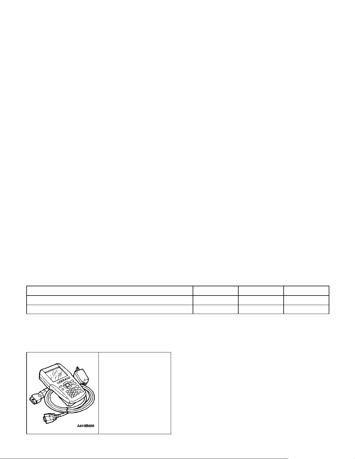
SPECIAL TOOLS TABLE
Scan Tool
Page 3

9T – 2IIMMOBILIZER ANTI–THEFT SYSTEM
Unauthorized use of a scan tool could be a method of defeating the immobilizer anti–theft system. Therefore, cer-
DIAGNOSIS
IMMOBILIZERANTI–THEFT SYSTEM
The immobilizer anti–theft system requires diagnosis
when it is not possible to start the engine. If the no–start
condition occurs because of the immobilizer system, a
diagnostic trouble code (DTC) 53 should be set.
The immobilizer anti–theft system requires diagnosis
when it is not possible to start the engine. If the no–start
condition occurs because of the immobilizer system, a
diagnostic trouble code (DTC) 53 should be set.
tain scan tool procedures require the use of a password.
The following functions are password protected:
S Coding of an additional key.
S Deleting all key codes.
S Deletion of the immobilizer identification (ID) code.
S Deletion of the powertrain control module
(PCM)/engine control module (ECM) ID code.
The following functions do not require a password:
S Reading an ignition key to determine if the trans-
ponder is working or if a key is authorized.
S Reading the immobilizer ID code to verify that it
matches the PCM/ECM ID code.
DTC 53 – PCM/ECM Immobilized Error
Step Action Value(s) Yes No
1 Connect the scan tool using the following procedure:
1. Insert the immobilizer data cartridge into the
scan tool.
2. Turn the ignition OFF.
3. Connect the scan tool to the data link connector DLC).
4. Turn the ignition ON, but do not start the engine.
Is communication established between the scan tool
and the immobilizer control unit?
2 Select SYSTEM DIAGNOSIS from the scan tool
menu.
Does the KEY STATUS message indicate POS NR
(position number) 00?
3 Read the IMMO & PCM/ECM ID–CODE message
that is displayed after requesting SYSTEM DIAGNOSIS.
Does the message ID–CODE DIFFERENT appear?
4 Check for an open serial data wire between the im-
mobilizer control unit and the powertrain control
module (PCM)/engine control module (ECM).
Is the circuit open?
5 Repair the open serial data wire between the PCM/
ECM and the immobilizer control unit.
Is the repair complete?
6
1. Replace the ECM.
2. Reprogram the identification (ID) code. Refer
to”ID Code Reprogramming” in this section.
Is the repair complete?
Go to Step 2 Go to ”Commu-
tween Immobi-
Go to ’Key
Status Errors”
Go to ”ID
Code Repro-
gramming”
Go to Step 5 Go to Step 6
System OK
System OK
nication Be-
lizer and Test
Equipment”
Go to Step 3
Go to Step 4
KEY STATUS ERRORS
The following KEY STATUS messages may be shown on
the scan tool after commanding SYSTEM DIAGNOSIS:
S IGNITION OFF STATUS. This message informs
the technician that the ignition is OFF during the
key coding process. Turn the ignition ON during key
coding, but do not start the engine.
DAEWOO V–121 BL4
Page 4

IMMOBILIZER ANTI–THEFT SYSTEM 9T – 3
S KEY IS OCCUPIED. Only five keys may be coded.
If a new key is desired, the previous key codes
must be deleted. Up to five keys may then be authorized.
S ALREADY AUTHORIZED. Key coding is being at-
tempted with a key that is already authorized.
S ERROR NO. 001, 002, 003. There is no commu-
nication between the transponder in the ignition key
and the detection coil. Follow the steps below to
diagnose the problem:
1. Try a different key. If a different key works, the
problem is in the original key.
2. If trying a different key results in the same error
message, replace the detection coil.
S INVALID KEY. The communication between the
immobilizer control unit and the key transponder
has not validated the key. Follow the steps below to
diagnose the problem:
1. Code the key. Refer to”Key Coding Procedure”in
this section.
2. If the same message is received after key coding,
check the connection of the detection coil.
3. If the detection coil is okay, replace the immobilizer.
Refer to”Immobilizer Control Unit” in this section.
S NO TRANSPONDER DETECTED. The fault may
be in ignition key transponder, the detection coil, or
the immobilizer. Follow the steps below to diagnose
the problem:
1. Try a different key. If a different key works, the
problem is in the original key.
2. If trying a different key results in the same error
message, check the connection of the detection
coil.
3. If the connection of the detection coil is okay, disconnect the detection coil and use an ohmmeter to
check for an open detection coil.
4. If the detection coil is not open, replace the immobilizer control unit. Refer to”Immobilizer Control Unit”
in this section.
COMMUNICATION BETWEEN
IMMOBILIZER AND TEST
EQUIPMENT
1. Connect the test equipment as described in theScan Tool Equipment Manual.
2. If communication between the scan tool and the
test equipment is unsuccessful, wait 30 seconds
and try again.
3. If communication is not successful on the second
try, turn the ignition OFF, and check the wire and
the connectors between the immobilizer control unit
terminal 3 and the data link connector (DLC).
4. If the wire and the connectors between the DLC
and the immobilizer control unit are OK, replace the
immobilizer control unit. Refer to ”Immobilizer Control Unit”in this section.
DAEWOO V–121 BL4
Page 5

9T – 4IIMMOBILIZER ANTI–THEFT SYSTEM
MAINTENANCE AND REPAIR
ON–VEHICLE SERVICE
KEY CODING PROCEDURE
1. Install the immobilizer control unit cartridge in the
scan tool.
2. Turn the ignition OFF
3. Connect the scan tool.
4. Turn the ignition ON with the key to be coded.
5. Enter the four–digit password that enables service
personnel to use the scan tool for coding keys.
6. A lost key can be deleted only by deleting all keys
and reauthorizing the remaining keys as new keys.
If a key is lost, go to the next step. If no keys have
been lost but an additional key is desired, go to
Step 8.
7. Use the scan tool command DELETE ALL KEY
CODES.
8. Use the scan tool command AUTHORIZE ONE
ADDITIONAL KEY.
9. Repeat Steps 4, 5, and 6 until the immobilizer control unit has recorded all of the new keys or, after a
deletion, has reauthorized all of the remaining keys.
The immobilizer control unit can record a maximum
of five keys.
10. Return the system to the normal mode.
11. Turn the ignition OFF.
12. Turn the ignition ON.
13. Start the engine.
ID CODE REPROGRAMMING
Reprogram the identification (ID) code in the following situations:
1. An immobilizer control unit has been replaced.
2. An electronic control module (ECM) has been replaced.
If a valid key has been lost, refer to”Key Coding Procedure” in this section.
Reprogramming Procedure
1. Turn the ignition OFF. Reprogramming is not allowed while the engine is running.
2. Insert the immobilizer control unit cartridge into the
scan tool.
3. Turn the ignition ON, but do not start the vehicle.
4. Enter the four–digit password that enables service
personnel to use the scan tool for ID code reprogramming.
5. Use the scan tool to command RESET ID CODE.
DAEWOO V–121 BL4
Page 6
IMMOBILIZER ANTI–THEFT SYSTEM 9T – 5
6. Turn the ignition OFF and ON again, but do not
crank or start the engine. The powertrain control
module (PCM)/engine control module (ECM) will
reset the ECM ID code to match the new ID code
that was calculated and sent by the immobilizer
control unit when the ignition was first turned ON
after the reset command.
7. Return the system to the normal mode.
8. Turn the ignition OFF.
9. Turn the ignition ON.
10. Start the engine.
After reprogramming the ID code, the scan tool SYSTEM
DIAGNOSIS command can verify that the PCM/ ECM ID
code matches the immobilizer control unit ID code.
If the reprogramming procedure does not result in matching ID codes, check the electrical connectors for the serial
data wire between the immobilizer control unit and the
PCM/ECM.
TRANSPONDER
If a transponder is faulty, the ignition key must be replaced.
It is not possible to install a new transponder into a key.
DAEWOO V–121 BL4
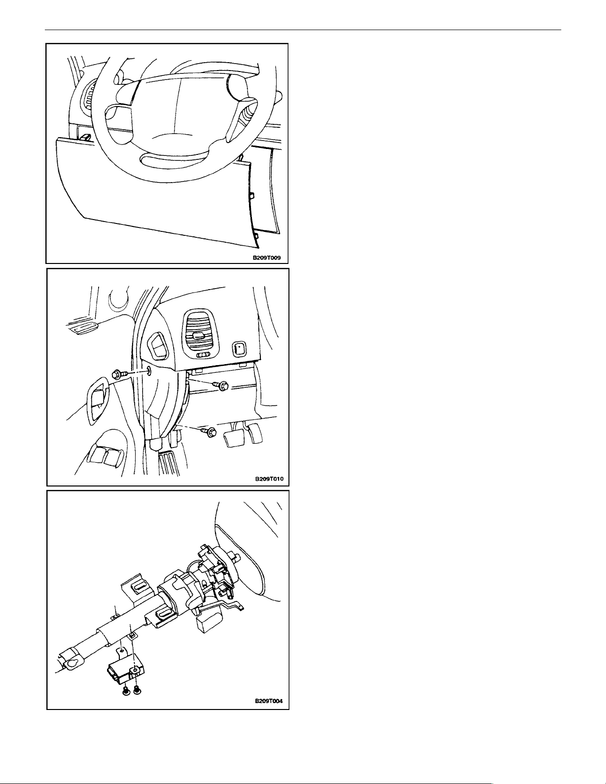
DETECTION COIL
Removal Procedure
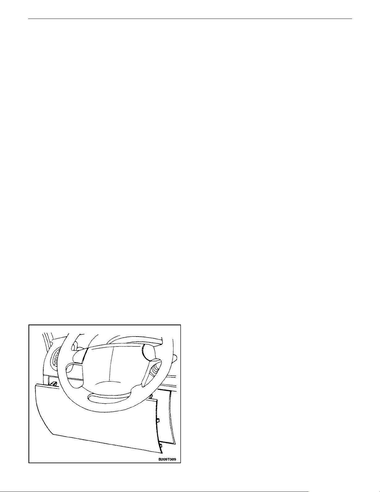
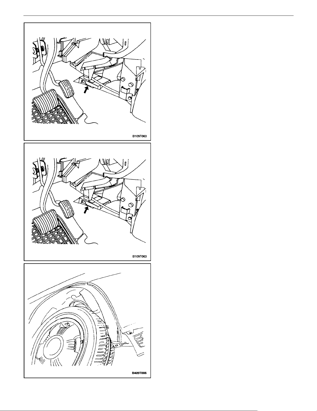
1. Carefully pull the knee bolster trim panel until it is
loose from its retaining clips.
Page 7
9T – 6IIMMOBILIZER ANTI–THEFT SYSTEM
2. Slide the knee bolster trim panel upward and pull it
outward to remove it.
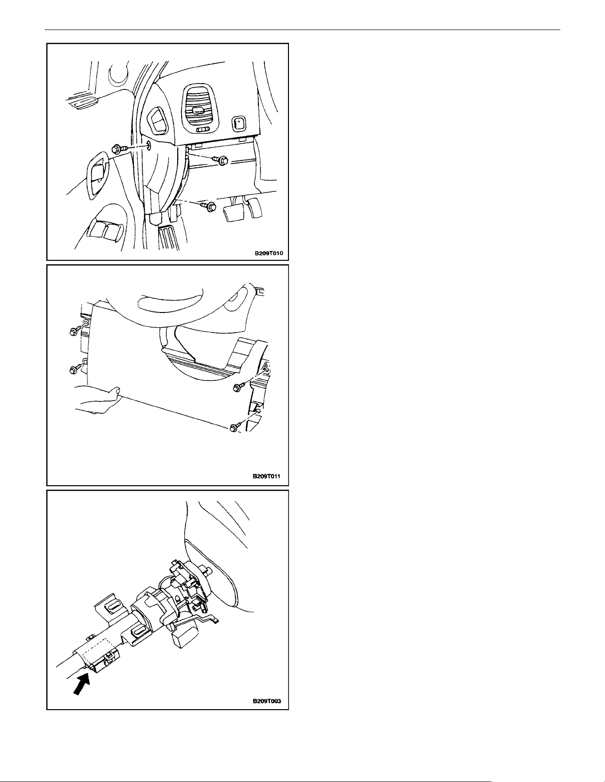
3. Remove the instrument panel side cover.
4. Remove the bolts and the knee bolster.
5. Remove the steering column lower cover. Refer
toSection 6E, Steering Wheel and Column.
6. Disconnect the two–pin connector from the immobilizer.
DAEWOO V–121 BL4
Page 8
IMMOBILIZER ANTI–THEFT SYSTEM 9T – 7
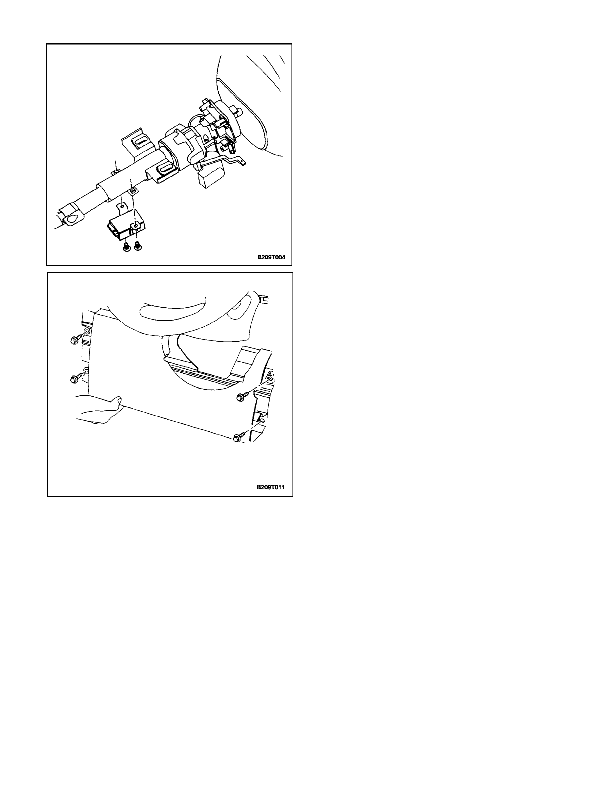
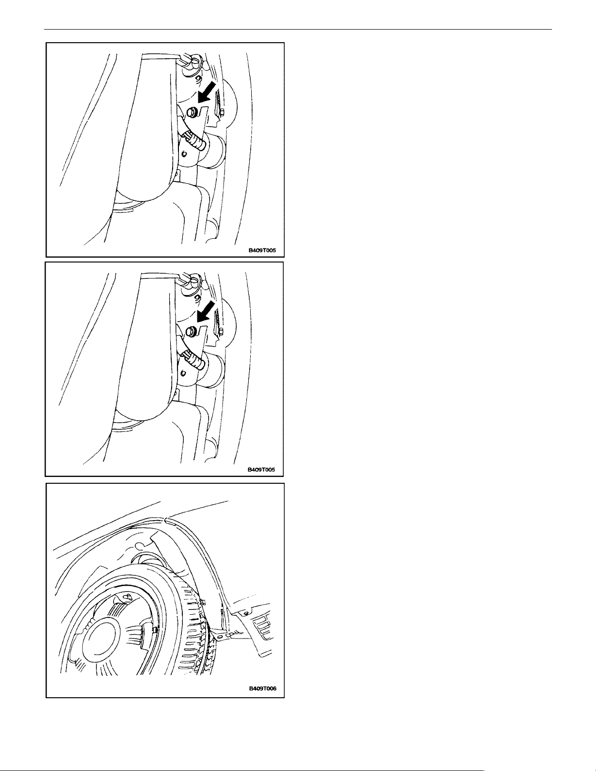
7. Pry the detection coil away from the lock cylinder. If
the detection coil will be replaced with a new one, it
does not matter if the key position trim ring is damaged during removal. A new trim ring is part of the
new detection coil.
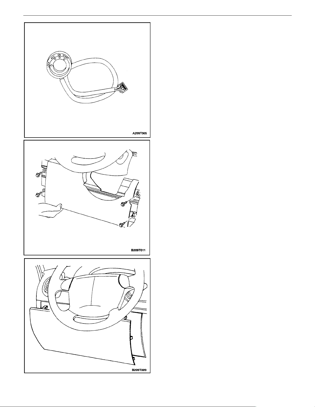
Installation Procedure
1. Install the detection coil by pressing it onto the lock
cylinder until it snaps in place.
2. Connect the two–pin connector to the immobilizer.
3. Install the steering column lower cover. Refer to
Section 6E, Steering Wheel and Column.
4. Install the knee bolster with the bolts.
Tighten
Tighten the knee bolster mounting bolts to 22 NSm (16
lb–ft)
DAEWOO V–121 BL4
5. Install the instrument panel side cover.
6. Install the knee bolster trim panel.
Page 9
9T – 8IIMMOBILIZER ANTI–THEFT SYSTEM
IMMOBILIZER CONTROL UNIT
Removal Procedure
1. Disconnect the negative battery cable.
2. Carefully pull the knee bolster trim panel loose from
its retaining clips.
3. Slide the knee bolster trim panel upward and pull it
outward to remove it.
4. Remove the instrument panel side cover.
5. Remove the bolts and the knee bolster.
6. Remove the bolts and the immobilizer control unit.
7. Disconnect the electrical connectors from the immobilizer control unit.
DAEWOO V–121 BL4
Page 10
IMMOBILIZER ANTI–THEFT SYSTEM 9T – 9
Installation Procedure
1. Connect the electrical connectors to the immobilizer
control unit.
2. Install the immobilizer control unit with the bolts.
Tighten
Tighten the immobilizer control unit mounting bolts to
4 NSm (35 lb–in).
3. Install the knee bolster with the bolts.
Tighten
Tighten the knee bolster mounting bolts to 22 NSm (16
lb–in).
4. Install the instrument panel side cover.
5. Install the knee bolster trim panel.
6. Connect the negative battery cable.
Important : After replacing the immobilizer, the keys must
be re–authorized using the key coding procedure. Refer
to”Key Coding Procedure” in this section. Also, the electronic control module (ECM) identification (ID) code must
be reset. Refer to”ID Code Reprogramming” in this section.
DAEWOO V–121 BL4
Page 11

9T – 10IIMMOBILIZER ANTI–THEFT SYSTEM
GENERAL DESCRIPTION
AND SYSTEM OPERATION
the radio–frequency signal. A release message is sent to
the powertrain control module (PCM)/engine control module (ECM) if the key is authorized.
New keys are coded by using a scan tool. Refer to in this
section.”Key Coding Procedure”
IMMOBILIZER SYSTEM
The purpose of the immobilizer system is to prevent the
vehicle from being stolen or driven by unauthorized users.
Users are authorized by an electronically coded key.
When the ignition is turned ON, the key is tested by the immobilizer system. While the key code is being read by the
immobilizer control unit, the engine can start and run with
any key that will turn the lock cylinder. The key code is read
and compared with key codes that have been stored in the
immobilizer control unit’s memory.
If a valid key is detected, the immobilizer control unit sends
a serial data release message to the powertrain control
module (PCM)/engine control module (ECM). Included in
the release message is an identification (ID) code which
assures that neither the immobilizer control unit nor the
PCM/ECM has been substituted to defeat the system.
If the PCM/ECM does not receive a release message within a specified time, or if the ID codes do not match, the
PCM/ECM performs the following actions:
S Disables the fuel injector circuit.
S Disables the fuel pump circuit.
S Disables the ignition coil.
S Sets diagnostic trouble code (DTC) 53.
The above conditions are maintained until the ignition is
turned OFF.
The immobilizer control unit system consists of the following components:
S Electronically coded keys.
S Detection coil.
S Immobilizer control unit.
S PCM/ECM.
S Instrument cluster indicator.
S A data link connector (DLC) to provide serial data
access for a scan tool.
DETECTION COIL
A detection coil is mounted at the ignition lock as an integral part of the key position trim ring. The wires to and from
the detection coil are connected to the immobilizer. When
the ignition is turned ON, the immobilizer energizes the
detection coil and the coil is coupled inductively to the
transponder in the ignition key. The immobilizer sends a
modulated signal to the detection coil. The signal is
changed by interaction with the internal transponder in the
ignition key. The immobilizer reads the signal from the
detection coil and determines whether the key is authorized.
IMMOBILIZER CONTROL UNIT
The immobilizer control unit is an electronic module in the
instrument panel which verifies the validity of an ignition
key when the ignition is turned ON.
To accomplish its purpose, the immobilizer control unit
performs the following actions:
S Learns and stores the codes of valid keys.
S Reads the radio frequency input from the ignition
key.
S Compares the received code with the codes of the
valid keys.
S Sends a release message to the powertrain control
module (PCM)/engine control module (ECM) if a
valid key has been presented.
S Calculates and transmits identification (ID) codes
within each release message.
S Controls the external relay which interrupts the
starter relay circuit.
S Controls the status indicator in the instrument clus-
ter.
S Monitors system faults.
S Supports system test functions.
A PCM/ECM for a vehicle without an immobilizer control
unit cannot be interchanged with a PCM/ECM that is used
with an immobilizer control unit system. The immobilizer
control unit and the PCM/ECM must have a matching ID
code. ID coding and key coding are accomplished by using
a scan tool.
ELECTRONICALLY CODED KEYS
Each valid ignition key has an internal transponder which
transmits a unique code. When a key is inserted into the
ignition lock, the transponder is inductively coupled to the
detection coil. The transponder interacts with the detection coil to generate an amplitude modulated modulated
signal which is conducted from the detection coil to the immobilizer control unit. The immobilizer control unit reads
Normal Operation
When the ignition is turned ON, the immobilizer control
unit tries to read the key code transmitted by the transponder in the ignition key.
If a valid key is detected, the immobilizer control unit sends
a release message to the PCM/ECM. The release message contains an ID code. Immobilization will be performed by the PCM/ECM if no release message is received, or if the ID code in the PCM/ECM does not match
the immobilizer control unit ID code.
If a non–valid key is detected, the release message is not
sent to the PCM/ECM.
When the driver turns the ignition OFF, the immobilizer
control unit switches to the active mode.
DAEWOO V–121 BL4
Page 12

IMMOBILIZER ANTI–THEFT SYSTEM 9T – 11
Data Link Connector (DLC)
When the ignition is ON, a scan tool can switch the immobilizer control unit to the data link connector (DLC) mode
for the purpose of diagnostics, key coding, or ID coding.
ID Code Handling
One of 65,535 possible ID codes is stored in the immobilizer control unit’s memory.
The ID code can be erased by using the scan tools’RESET
ID CODE command. When the immobilizer control unit
calculates a new ID code, the PCM/ECM ID code must be
reset to match the immobilizer control unit ID code. To reset the ID code, refer to ”ID Code Reprogramming.”
During diagnostic procedures, the ID code can be read for
comparison with the PCM/ECM ID code by using the scan
tool’s READ IMMOBILIZER CONTROL UNIT IDCODE
command.
SERIAL DATA LINK
Serial data can be exchanged between a scan tool, the
powertrain control module (PCM)/engine control module
ECM), and the immobilizer control unit.
The scan tool connection is the data link connector (DLC).
POWERTRAIN CONTROL MODULE
(PCM)/ENGINE CONTROL MODULE
(ECM)
When the powertrain control module (PCM)/engine con-
trol module (ECM) detects that the ignition is being turned
ON, the PCM/ECM waits for a release message from the
immobilizer control unit. If a release message is not received within a specified time, the PCM/ECM disables the
engine. The engine is also disabled if the identification (ID)
code transmitted by the immobilizer control unit does not
match the code stored in the PCM/ECM’s memory. Immobilization remains in effect until the ignition is turned OFF,
or until battery power is removed.
To prevent the vehicle from being driven, the PCM/ECM
applies the following strategy:
S The ignition module is put in a bypass mode.
S The PCM/ECM will not create an electronic spark
timing (EST) output. Therefore, no spark will be
generated by the ignition coil.
S The PCM/ECM will not enable the fuel pump.
S The PCM/ECM will not enable the fuel injectors.
S The PCM/ECM sets diagnostic trouble code (DTC)
53.
Serial data communication is transmitted on a single wire
between the immobilizer control unit and the PCM/ ECM.
During diagnostic procedures or ID code changing, a scan
tool is added to the communication system.
A PCM/ECM with an immobilizer control unit is not exchangeable with a PCM/ECM that does not have an immobilizer control unit.
DAEWOO V–121 BL4
Page 13

SECTION : 9T
REMOTE KEYLESS ENTRY AND
PERIMETER/ULTRASONIC ANTI–THEFT SYSTEM
CAUTION : Disconnect the negative battery cable before removing or installing any electrical unit or when a tool
or equipment could easily come in contact with exposed electrical terminals. Disconnecting this cable will help
prevent personal injury and damage to the vehicle. The ignition must also be in LOCK unless otherwise noted.
TABLE OF CONTENTS
SPECIFICATIONS 9T–1. . . . . . . . . . . . . . . . . . . . . . . . . .
FASTENER TIGHTENING SPECIFICATIONS 9T–1.
SCHEMATIC AND ROUTING DIAGRAMS 9T–2. . . . .
REMOTE KEYLESS ENTRY AND ANTI–THEFT
SYSTEM (1 OF 2) 9T–2. . . . . . . . . . . . . . . . . . . . . . .
REMOTE KEYLESS ENTRY AND ANTI–THEFT
SYSTEM (2 OF 2) 9T–3. . . . . . . . . . . . . . . . . . . . . . .
CONTROL MODULE/RECEIVER CONNECTOR 9T–
4
WIRING HARNESS CONNECTORS 9T–4. . . . . . . . .
MAINTENANCE AND REPAIR 9T–5. . . . . . . . . . . . . . .
ON–VEHICLE SERVICE 9T–5. . . . . . . . . . . . . . . . . . . . .
CONTROL MODULE/RECEIVER 9T–5. . . . . . . . . . . .
SIREN 9T–5. . . . . . . . . . . . . . . . . . . . . . . . . . . . . . . . . . .
FRONT DOOR TAMPER SWITCH 9T–7. . . . . . . . . . .
REAR DECK LID TAMPER SWITCH 9T–7. . . . . . . . .
SPECIFICATIONS
HOOD OPEN SWITCH 9T–8. . . . . . . . . . . . . . . . . . . . .
PASSWORD PROGRAMMING 9T–10. . . . . . . . . . . . .
GENERAL DESCRIPTION AND SYSTEM
OPERATION 9T–11. . . . . . . . . . . . . . . . . . . . . . . . . . . . . .
REMOTE KEYLESS ENTRY AND ANTI–THEFT
SYSTEM 9T–11. . . . . . . . . . . . . . . . . . . . . . . . . . . . . . .
REMOTE LOCKING AND UNLOCKING 9T–11. . . . . .
SECURITY INDICATOR 9T–11. . . . . . . . . . . . . . . . . . . .
INTRUSION SENSING 9T–11. . . . . . . . . . . . . . . . . . . . .
SIREN 9T–11. . . . . . . . . . . . . . . . . . . . . . . . . . . . . . . . . . .
VEHICLE LOCATOR 9T–12. . . . . . . . . . . . . . . . . . . . . .
AUTOLOCKING (SAFETY LOCK) 9T–12. . . . . . . . . .
CONTROL MODULE/RECEIVER 9T–12. . . . . . . . . . .
FAULT OR ALARM INDICATION 9T–12. . . . . . . . . . .
PANIC BUTTON 9T–12. . . . . . . . . . . . . . . . . . . . . . . . . .
FASTENER TIGHTENING SPECIFICATIONS
Application NSm Lb–Ft Lb–In
Hood Open Switch Mounting Screw 8 – 71
Siren Bracket Mounting Bolt 22 16 –
Page 14
9T – 2IREMOTE KEYLESS ENTRY AND ANTI–THEFT SYSTEM
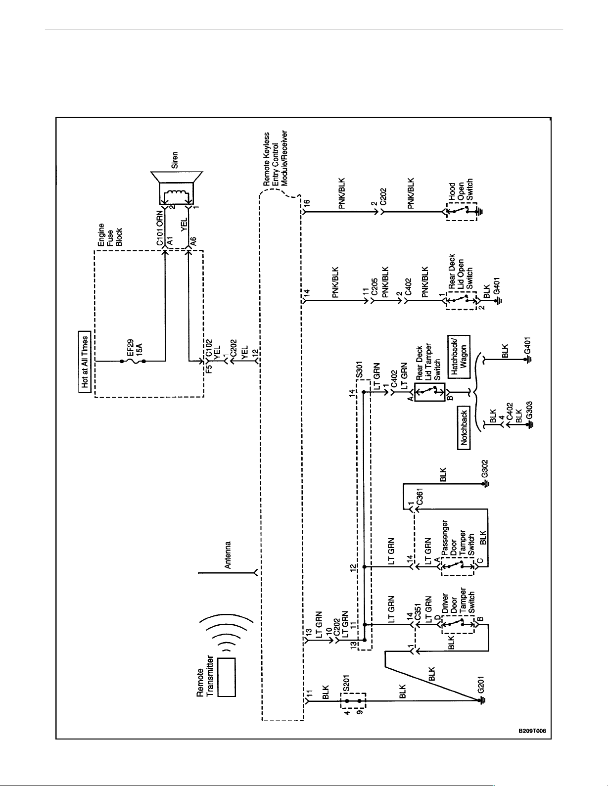
SCHEMATIC AND ROUTING DIAGRAMS
REMOTE KEYLESS ENTRY AND ANTI–THEFT SYSTEM (1
OF 2)
DAEWOO V–121 BL4
Page 15
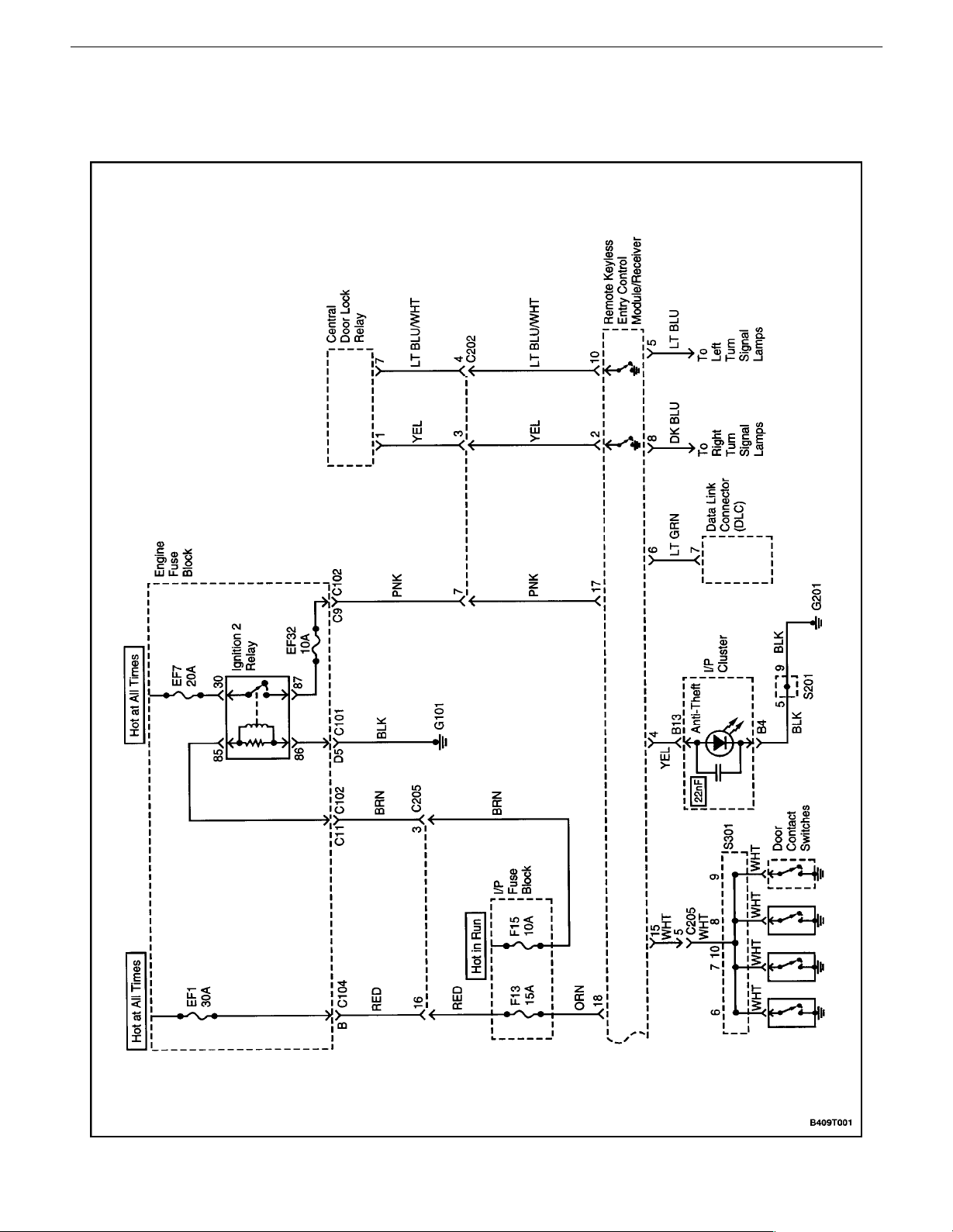
REMOTE KEYLESS ENTRY AND ANTI–THEFT SYSTEM 9T – 3
REMOTE KEYLESS ENTRY AND ANTI–THEFT SYSTEM (2
OF 2)
DAEWOO V–121 BL4
Page 16
9T – 4IREMOTE KEYLESS ENTRY AND ANTI–THEFT SYSTEM
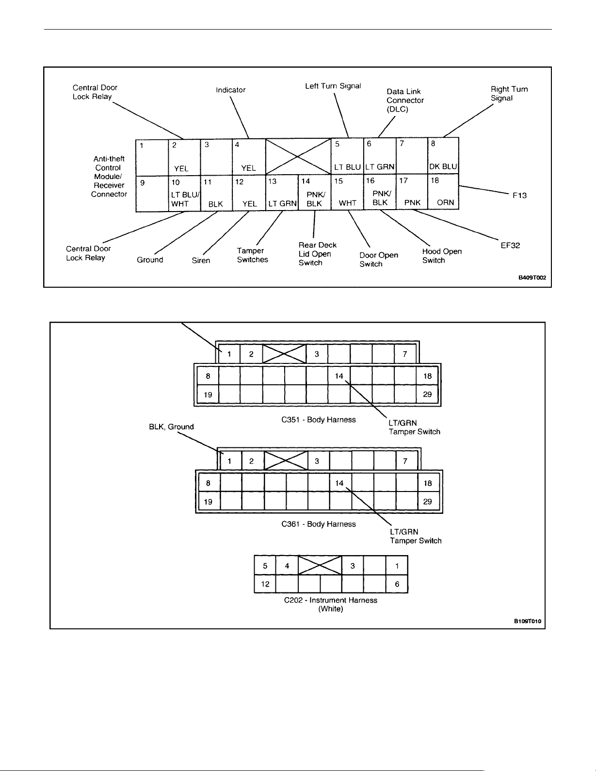
CONTROL MODULE/RECEIVER CONNECTOR
WIRING HARNESS CONNECTORS
DAEWOO V–121 BL4
Page 17
REMOTE KEYLESS ENTRY AND ANTI–THEFT SYSTEM 9T – 5
MAINTENANCE AND REPAIR
ON–VEHICLE SERVICE
CONTROL MODULE/RECEIVER
Removal Procedure
1. Disconnect the negative battery cable.
2. Remove floor console left side forward trim panel.
Refer to Section 9G, Interior Trim.
3. Disconnect the control module/receiver electrical
connector.
4. Slide the control module/receiver toward the rear of
the vehicle and remove it.
Installation Procedure
1. Install the control module/receiver by sliding it onto
its bracket.
2. Connect the control module/receiver electrical connector.
3. Install the floor console left side forward trim panel.
Refer to Section 9G, Interior Trim.
4. Connect the negative battery cable.
DAEWOO V–121 BL4
SIREN
Removal Procedure
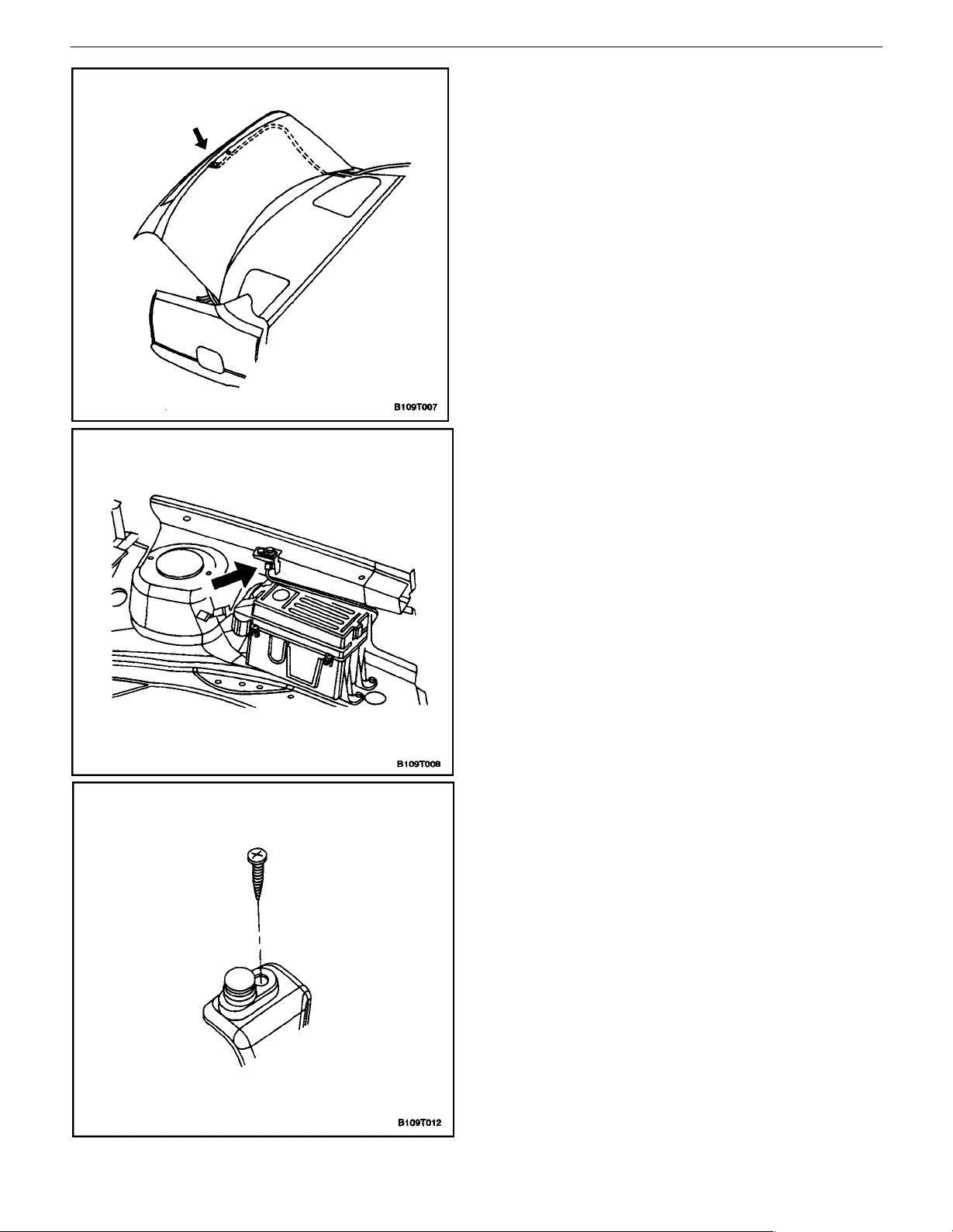
1. Remove several screws to boosen the forward half
of the right front wheel well splash shield.
Page 18
9T – 6IREMOTE KEYLESS ENTRY AND ANTI–THEFT SYSTEM
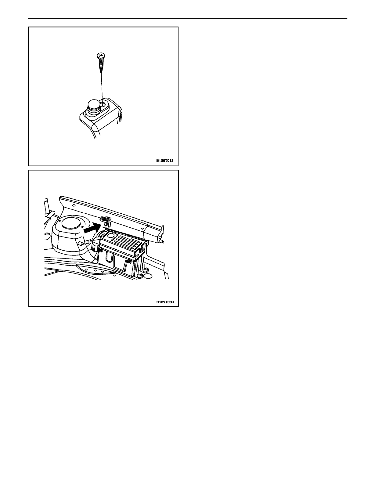
2. Remove the siren electrical connector.
3. Remove the siren bracket mounting bolt.
4. Remove the siren.
Installation Procedure
1. Install the siren on the siren bracket with the mounting screws.
Tighten
Tighten the siren bracket mounting bolts to 22 NSm
(16 lb–in).
2. Connect the siren electrical connector.
DAEWOO V–121 BL4
Page 19
REMOTE KEYLESS ENTRY AND ANTI–THEFT SYSTEM 9T – 7
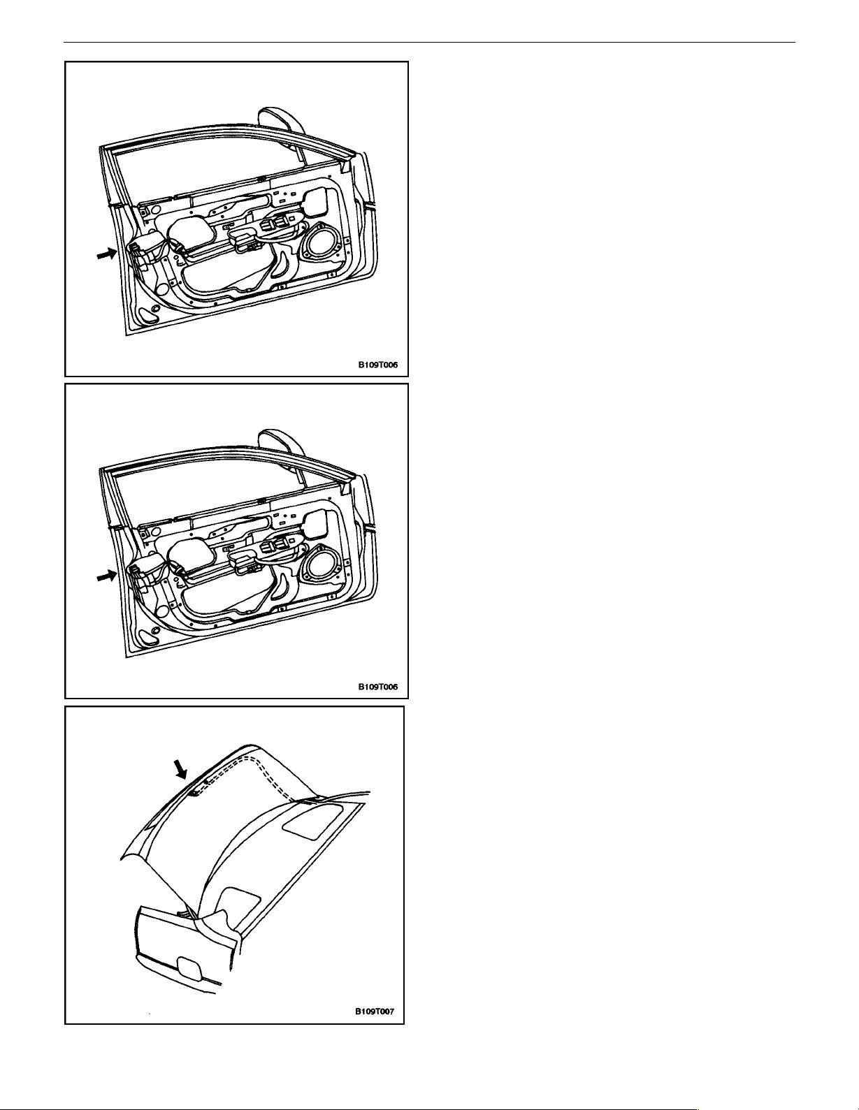
FRONT DOOR TAMPER SWITCH
Removal Procedure
1. Disconnect the negative battery cable.
2. Remove the front door trim panel. Refer to Section
9G, Interior Trim.
3. Disconnect the door tamper switch electrical connector.
4. Remove the front door lock and the integral door
tamper switch. Refer toSection 9P, Doors.
Installation Procedure
1. Install the front door lock and the integral door tamper switch. Refer toSection 9P, Doors.
2. Install the door tamper switch electrical connector.
3. Install the front door trim panel. Refer to Section
9G, Interior Trim.
4. Connect the negative battery cable.
DAEWOO V–121 BL4
REAR DECK LID TAMPER SWITCH
Removal Procedure
1. Disconnect the negative battery cable.
2. Disconnect the rear deck lid tamper switch electrical connector from the tamper switch.
3. Remove the rear deck lid tamper switch.
Page 20
9T – 8IREMOTE KEYLESS ENTRY AND ANTI–THEFT SYSTEM
Installation Procedure
1. Install the rear deck lid tamper switch.
2. Connect the rear deck lid tamper switch electrical
connector to the tamper switch.
3. Connect the negative battery cable.
HOOD OPEN SWITCH
Removal Procedure
1. Disconnect the negative battery cable.
2. Disconnect the electrical connector from the hood
open switch.
3. Remove the mounting screw from the hood open
switch.
4. Remove the hood open switch.
DAEWOO V–121 BL4
Page 21
REMOTE KEYLESS ENTRY AND ANTI–THEFT SYSTEM 9T – 9
Installation Procedure
1. Install the hood open switch with the mounting
screw.
Tighten
Tighten the hood open switch mounting screw to 8
NSm (71 lb–in).
2. Connect the electrical connector to the hood open
switch.
3. Connect the negative battery cable.
DAEWOO V–121 BL4
Page 22

9T – 10IREMOTE KEYLESS ENTRY AND ANTI–THEFT SYSTEM
PASSWORD PROGRAMMING
If a transmitter is lost or damaged, the control module/receiver must be re–programmed to communicate with a
new transmitter. The passwords recorded in the control
module/receiver should not be deleted when power is off
in the control module/receiver.
Each control module/receiver should be able to record five
passwords. The following method is used to record new
passwords in the control module/receiver:
1. Connect the scan tool to the assembly line diagnostic link (ALDL) connector.
2. Turn the ignition ON.
3. Delete the current passwords.
4. Send the programming mode message to the control module/receiver.
5. Press any button of the transmitter to generate a
data code including a password which will be recorded by the control module/receiver. The control
module/receiver sends a response message to the
scan tool to indicate that the first password has
been recorded.
6. Press any button of the transmitter to generate a
data code including a password which will be recorded by the control module/receiver. The control
module/receiver sends a response message to the
scan tool to indicate that the second password has
been recorded.
7. Press any button of the transmitter three more
times until the control module/receiver has responded that the third, fourth, and fifth passwords
have been recorded.
8. Turn the ignition OFF.
9. Disconnect the scan tool.
The control module/receiver automatically leaves the programming mode and switches to the normal operating
mode when either of the following conditions occurs:
S The scan tool is disconnected from the ALDL.
S Five passwords are recorded in the control module/
receiver.
DAEWOO V–121 BL4
Page 23

REMOTE KEYLESS ENTRY AND ANTI–THEFT SYSTEM 9T – 11
GENERAL DESCRIPTION
AND SYSTEM OPERATION
REMOTE KEYLESS ENTRY AND
ANTI–THEFT SYSTEM
The remote keyless entry and anti–theft system can per-
form the following functions:
S Remotely lock and unlock the vehicle doors with a
hand–held high–frequency transmitter.
S Sense intrusion into the vehicle through the doors,
the trunk, or the hood.
S Activate a warning to signal an intrusion.
S Help the driver find the vehicle in a parking area.
S Automatically re–lock the doors if a door or the
trunk is not opened within 30 seconds after the vehicle has been unlocked by the remote keyless
entry.
S Communicate serial data to a scan tool to help
diagnose system faults.
The remote keyless entry and anti–theft system consists
of the following components:
S Keyless entry and anti–theft control module/receiv-
er.
S Security indicator.
S Rear deck lid open switch.
S Rear deck lid tamper switch.
S Front door tamper switches.
S Door open switches.
S Central locking unit.
S Flashing turn signal lamps.
S Siren.
S Hood open switch.
REMOTE LOCKING AND UNLOCKING
The transmitter has a replaceable battery. The battery is
designed to last at least three years before replacement
is necessary.
SECURITY INDICATOR
There is a security indicator on the instrument panel. After
the LOCK button of the transmitter is pressed, the module
is placed in the armed mode, and the security indicator
flashes. The security indicator turns ON for 0.1 second
and OFF for 0.7 second. It then flashes at that frequency
until the control module/receiver is disarmed. If the vehicle
is equipped with an immobilizer, the security indicator is
connected to the immobilizer system instead of the keyless entry/anti–– theft system.
INTRUSION SENSING
The anti–theft function is armed if the transmitter sends
the LOCK message to the control module/receiver when
the ignition is OFF.
When the hood, the door, or the rear deck lid is opened,
the hood open switch, the door open switch, or the trunk
open switch will change its input to ground. The alarm will
be activated if the hood open sensor, the door open sensor, or the trunk open sensor changes its input to ground
before either of the following conditions occurs:
S An UNLOCK message is received from the trans-
mitter.
S The front door tamper switch or the rear deck lid
tamper switch indicates key operation by changing
its input to ground.
The alarm also will be activated if the ignition input is
changed to battery voltage before either of the following
conditions occurs:
S An UNLOCK message is received from the trans-
mitter.
S The front door tamper switch or the rear deck lid
tamper switch indicates key operation by changing
its input to ground.
The hand–held transmitter locks and unlocks the vehicle
doors by sending radio waves to the control module/receiver in the vehicle. The effective range of the transmitter
varies between 5 and 10 meters (approximately 16 to 32
feet), depending on whether or not objects such as other
vehicles are blocking the path of the radio waves.
The transmitter has a LOCK button and an UNLOCK button which only function when the ignition is OFF. Pressing
the UNLOCK button has the following effects:
S The doors are unlocked.
S The turn signal lamps flash twice.
S The control module is disarmed.
Pressing the LOCK button has the following effects:
S The doors are locked.
S The turn signal lamps flash once.
S The control module is armed.
DAEWOO V–121 BL4
SIREN
The remote keyless entry system is armed when the
LOCK message is received from the transmitter when the
ignition is OFF. When the system is armed, it will activate
the siren and flash the turn signals for 28 seconds if any
of the following conditions occurs:
S A door is opened without using the key (front door
open switch input is changed to ground).
S The rear deck lid is opened without using the key
trunk open switch input is changed to ground).
S The hood is opened while the anti–theft system is
armed (hood open switch input is changed to
ground).
S The ignition switch input is changed to battery volt-
age.
The siren is disarmed when any of the following conditions
occurs:
Page 24

9T – 12IREMOTE KEYLESS ENTRY AND ANTI–THEFT SYSTEM
S The door is opened with the key.
S The rear deck lid is opened with the key.
S The UNLOCK button or the LOCK button on the
remote transmitter is pressed within 2 seconds of
the beginning of the alarm. If the UNLOCK button
or the LOCK button is not pressed within 2 seconds
of the beginning of the alarm, the transmitter will
not stop the alarm.
VEHICLE LOCATOR
The remote keyless entry system assists the driver in locating the vehicle. When the vehicle is unlocked with the
remote control, the turn signals flash twice to indicate the
location of the vehicle. The duration of the flashes and the
length of time between flashes is used to indicate certain
vehicle conditions. Refer to ”Fault or Alarm Indication” in
this section.
AUTOLOCKING (SAFETY LOCK)
The remote keyless entry system features an autolocking
control. If the doors are unlocked with the remote transmitter when the control module/receiver is in the armed
mode, the doors are automatically re–locked after 30 sec-
onds unless any of the following events occur:
S The door is opened.
S The ignition switch is turned ON.
S The rear deck lid is opened.
S The hood is opened.
CONTROL MODULE/RECEIVER
The remote keyless entry control module/receiver is contained in the floor console. The module/receiver processes signals from the remote transmitter and the intrusion sensors, and it activates the alarm if an intrusion is
detected. The control module/receiver also has a selfdiagnostic function which will display trouble codes. In order to
display trouble codes, a scan tool must be connected to
the assembly line diagnostic link (ALDL) connector.
The control module/receiver will not communicate with
transmitters from other vehicles because there are over
four billion possible electronic password combinations,
and passwords are not duplicated. The control module/ receiver has an attached antenna to detect signals from the
transmitter.
FAULT OR ALARM INDICATION
When the UNLOCK button on the remote transmitter is
pressed, the control module/receiver will flash the parking
lamps to indicate information about the remote keyless
entry and anti–theft system.
Normal Condition: If there has not been an intrusion, and
no fault has been detected, the control module/receiver
will signal a normal condition when the UNLOCK button is
pressed. The parking lamps will flash twice for 0.5 second,
with a 0.5 second pause between flashes.
Fault Indication: If there is a fault in the remote keyless
entry and anti–theft system, the control module/receiver
will signal the fault when the UNLOCK button is pressed.
The parking lamps will flash twice for 1 second, with a 0.5
second pause between flashes.
Alarm Indication: If there has been an intrusion since the
last time the LOCK button was pressed, the control module/receiver will signal that there has been an intrusion
when the UNLOCK button is pressed. The parking lamps
will flash twice for 0.5 second, with a 1.5 second pause between flashes.
Alarm and fault information in the control module/receiver
will be erased the next time the controlmodule/receiver enters the armed condition after receiving a LOCK message
from the transmitter.
PANIC BUTTON
In addition to the LOCK and UNLOCK buttons on the
transmitter, there is the panic button. This button is used
to activate the siren if a threatening situation occurs while
the driver is approaching the vehicle. If the panic button is
held down for 2 seconds, the siren will be activated for 30
seconds, and the parking lights will flash during that time.
DAEWOO V–121 BL4
Page 25

TECHNICAL SERVICE BULLETIN
TECHNICAL SERVICE BULLETIN
Bulletin No.:
Model(s):
Date:
VIN Range:
TSB-003-01
All
May 18, 2001
All
Description:
Group:
Reference:
Prod. Dates:
Remote Keyless Entry Transmitter
Programming
Body
N/A
All
Remote Keyless Entry Transmitter Programming Information
The Daewoo Remote Keyless Entry System allows for the use of as many as five (5)
transmitters for each vehicle. Replacement Remote Keyless Entry System Transmitters must
first be programmed to a specific vehicle using the Scan 100 Scan Tool. This process is
completed using serial data communication between the Scan 100 Scan Tool and the Remote
Keyless Entry Control Unit and is the only method available for programming Transmitters.
Note: All Transmitters for a specific vehicle must be programmed at the same time.
Once the programming function of the Remote Keyless Entry System is
activated, any Transmitter (existing or new) that is not programmed (or
reprogrammed) during the programming procedure will no longer operate the
Remote Keyless Entry System of that vehicle.
This Technical Service Bulletin provides information concerning the programming procedure
for the Remote Keyless Entry Transmitter(s).
REMOTE KEYLESS ENTRY TRANSMITTER PROGRAMMING PROCEDURE:
Note: Ensure that the doors, hood and trunk / rear hatch are closed prior to starting
the programming procedure.
1. Connect the Scan 100 Scan Tool to the Data Link Connector (DLC).
2. Turn the Scan 100 Scan Tool “ON” by pressing the “POWER” Button, then wait for the
MAIN MENU screen to be displayed.
3. From the MAIN MENU screen, select “Diagnostics” by pressing #1 on the Key Pad.
4. From the MODEL YEAR screen, select the appropriate model year of the specific vehicle
by either scrolling down to the year and pressing “ENTER”, or by pressing the respective
item number on the Key Pad.
5. From the VEHICLE TYPE screen, select the specific vehicle model by either scrolling
down to the model name and pressing “ENTER”, or by pressing the respective item
number on the Key Pad.
6. From the SYSTEM SELECTION MENU screen, select “Body” by pressing #2 on the Key
Pad.
7. From the BODY SELECTION MENU screen, select “Coding” by pressing #2 on the Key
Pad.
Circulate To:
√
General Manager
√
Service Manager
√
Technician(s)
√
Service Advisor
√
Body Shop Manager
√
Parts Manager
Page 26

Description Page
8. From the CODING SYSTEM screen, select “Coding Only” by pressing #1 on the Key
Pad.
9. From the SECRET NUMBER OF CODINGS screen, enter four (4) zero's (0-0-0-0) in the
four (4) boxes labeled “1-2-3-4”.
10. From the CODING SYSTEM SELECT screen, select “Keyless Entry” by pressing #2 on
the Key Pad.
Note: A slight delay may occur and “PLEASE WAIT” may be displayed before the next
11. From the KEYLESS ENTRY CODING SYSTEM screen, select “Coding Transmitter” by
pressing #1 on the Key Pad.
12. When directed by the Scan 100 Scan Tool, press any Button on the first Transmitter to
be programmed.
CAUTION: Ensure that Transmitters from other vehicles in the immediate area are not
13. Continue programming Transmitters when directed by the Scan 100 Scan Tool until all
Transmitters have been programmed.
Remote Keyless Entry Programming
screen appears.
activated during this procedure.
2 of 2
Note: A maximum of five (5) Transmitters may be programmed to a vehicle.
14. Once all Transmitters have been programmed, press the “ESC” Button on the Key Pad.
The display will confirm the number of Transmitters programmed. If the number
displayed does not match the number of Transmitters programmed, repeat the procedure.
15. Turn the Scan 100 Scan Tool “OFF” by pressing the “POWER” Button, then disconnect it
from the Data Link Connector.
16. Wait approximately 10 seconds, then test the operation of each programmed Transmitter
to ensure it operates properly.
If additional information is needed regarding this procedure, please contact your District Parts
& Service Manager or the Daewoo Technical Assistance Center toll free at (877) 362-1234,
selection 1.
May, 2001
Page 27

SECTION : 9D
WIPERS/WASHER SYSTEMS
CAUTION : Disconnect the negative battery cable before removing or installing any electrical unit or when a tool
or equipment could easily come in contact with exposed electrical terminals. Disconnecting this cable will help
prevent personal injury and damage to the vehicle. The ignition must also be in LOCK unless otherwise noted.
TABLE OF CONTENTS
SPECIFICATIONS 9D–1. . . . . . . . . . . . . . . . . . . . . . . . . .
FASTENER TIGHTENING SPECIFICATIONS 9D–1.
SCHEMATIC AND ROUTING DIAGRAMS 9D–2. . . . .
WIPERS AND WASHER SYSTEM (NOTCHBACK)9D
–2
WIPERS AND WASHER SYSTEM (HATCHBACK) 9D
–3
DIAGNOSIS 9D–4. . . . . . . . . . . . . . . . . . . . . . . . . . . . . . . .
WINDSHIELD WIPERS 9D–4. . . . . . . . . . . . . . . . . . . .
WINDSHIELD WASHER SYSTEM 9D–8. . . . . . . . . . .
REAR WINDOW WIPER (HATCHBACK AND
WAGON) 9D–9. . . . . . . . . . . . . . . . . . . . . . . . . . . . . . .
REAR WINDOW WASHER SYSTEM (HATCHBACK
AND WAGON) 9D–11. . . . . . . . . . . . . . . . . . . . . . . . .
MAINTENANCE AND REPAIR 9D–12. . . . . . . . . . . . . .
ON–VEHICLE SERVICE 9D–12. . . . . . . . . . . . . . . . . . . .
WINDSHIELD WIPER ARM 9D–12. . . . . . . . . . . . . . . .
SPECIFICATIONS
WINDSHIELD WIPER MOTOR 9D–12. . . . . . . . . . . . .
WINDSHIELD WIPER BLADE 9D–14. . . . . . . . . . . . . .
WINDSHIELD WIPER BLADE INSERT 9D–14. . . . .
WINDSHIELD WASHER RESERVOIR 9D–15. . . . . .
WINDSHIELD WASHER PUMP(S) 9D–17. . . . . . . . . .
WINDSHIELD WASHER NOZZLES 9D–18. . . . . . . . .
WINDSHIELD WASHER HOSES 9D–18. . . . . . . . . . .
REAR WINDOW WIPER ARM 9D–20. . . . . . . . . . . . .
REAR WINDOW WIPER MOTOR (HATCHBACK)9D–
20
REAR WINDOW WIPER MOTOR (WAGON) 9D–21.
REAR WINDOW WASHER NOZZLE (HATCHBACK) 9
D–22
GENERAL DESCRIPTION AND SYSTEM
OPERATION 9D–24. . . . . . . . . . . . . . . . . . . . . . . . . . . . .
WINDSHIELD WIPER SYSTEM 9D–24. . . . . . . . . . . .
WINDSHIELD WASHER SYSTEM 9D–24. . . . . . . . . .
REAR WINDOW WIPER/WASHER SYSTEM 9D–24
FASTENER TIGHTENING SPECIFICATIONS
Application NSm Lb–Ft Lb–In
Front Wheel Well Splash Shield Bolts 1.5 – 13
Washer Fluid Reservoir Bolts 8 – 71
Wiper Arm Linkage Nut 5 – 44
Wiper Arm Nut 11 – 97
Wiper Motor Bolts 8 – 71
Page 28
9D – 2IWIPERS/WASHER SYSTEMS
SCHEMATIC AND ROUTING DIAGRAMS
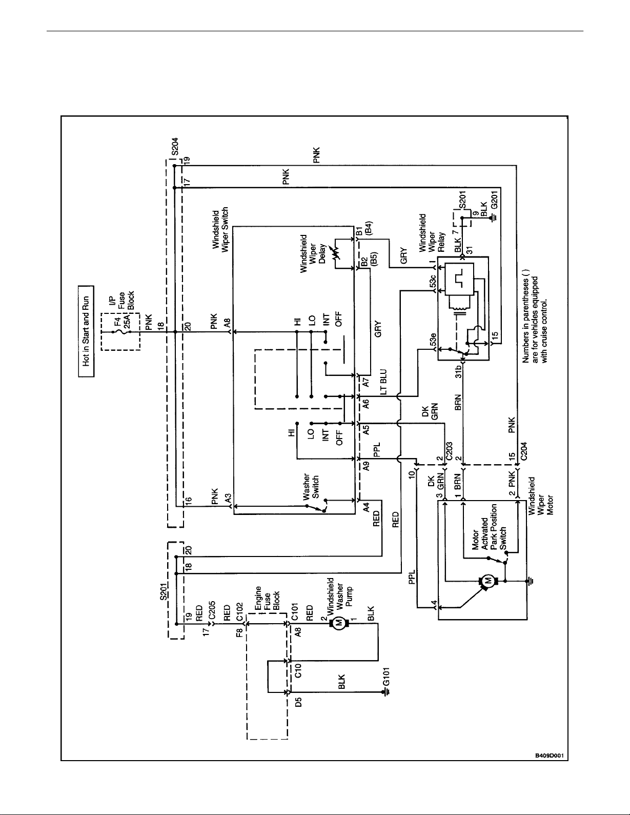
WIPERS AND WASHER SYSTEM (NOTCHBACK)
DAEWOO V–121 BL4
Page 29
WIPERS/WASHER SYSTEMS 9D – 3
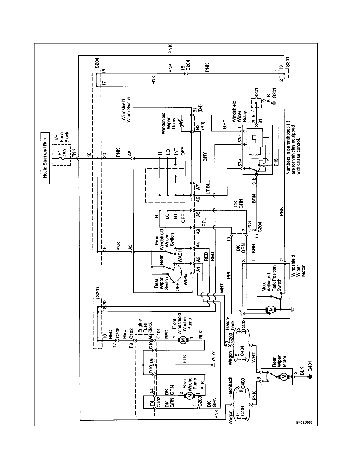
WIPERS AND WASHER SYSTEM (HATCHBACK)
DAEWOO V–121 BL4
Page 30

9D – 4IWIPERS/WASHER SYSTEMS
DIAGNOSIS
WINDSHIELD WIPERS
Windshield Wipers Do Not Work At Any Speed
Step Action Value(s) Yes No
1 Check fuse F4.
Is fuse F4 blown?
2
3 Check the voltage at fuse F4.
4 Repair the open power supply circuit to fuse F4.
5
6 Replace the wiper motor.
7
8 Repair the open circuit between the wiper switch
9
10 Replace the wiper switch.
11 Repair the open circuit between the wiper switch and
1. Check for a short circuit and repair it, if necessary.
2. Replace the fuse.
Is the repair complete?
Is the voltage equal to the specified value?
Is the repair complete?
1. Disconnect the wiper motor connector.
2. Turn the ignition ON.
3. Turn the wiper switch to HI.
4. Check the voltage at the wiper motor connector
terminal 6.
Is the voltage equal to the specified value?
Is the repair complete?
1. The wiper switch is still disconnected.
2. Turn the ignition ON.
3. Check for battery voltage at the wiper switch
connector terminal A8.
Is the voltage equal to the specified value?
connector terminal A8 and fuse F4.
Is the repair complete?
1. The wiper switch is still disconnected.
2. Turn the wiper switch to HI.
3. Use an ohmmeter to check for continuity between wiper switch terminal A8 and A9.
Does the ohmmeter indicate the specified value?
Is the repair complete?
the wiper motor.
Is the repair complete?
11–14 v Go to Step 5 Go to Step 4
11–14 v Go to Step 6 Go to Step 7
11–14 v Go to Step 9 Go to Step 8
[ 0 W Go to Step 11 Go to Step 10
Go to Step 2 Go to Step 3
System OK
System OK
System OK
System OK
System OK
System OK
DAEWOO V–121 BL4
Page 31

WIPERS/WASHER SYSTEMS 9D – 5
Wipers Do Not Work On HI Speed, LO Speed OK
Step Action Value(s) Yes No
1
2 Replace the wiper motor.
3
4 Replace the wiper switch.
5 Repair the open circuit between wiper switch con-
1. Turn the ignition ON.
2. Turn the wiper switch to HI.
3. Check the voltage at the wiper motor connector
terminal 4.
Is voltage equal to the specified value?
Is the repair complete?
1. Disconnect the wiper switch.
2. Turn the wiper switch to HI.
3. Use an ohmmeter to check for continuity between wiper switch terminal A8 and A9.
Does the ohmmeter indicate the specified value?
Is the repair complete?
nector terminal A9 and wiper motor connector terminal 4.
Is the repair complete?
11–14 v Go to Step 2 Go to Step 3
System OK
[ 0 W Go to Step 5 Go to Step 4
System OK
System OK
Wipers Do Not Work On LO Speed, HI Speed OK
Step Action Value(s) Yes No
1
2 Replace the wiper motor.
3
4 Replace the wiper switch.
5 Repair the open circuit between wiper switch con-
1. Turn the ignition ON.
2. Turn the wiper switch to LO.
3. Check the voltage at the wiper motor connector, terminal 3.
Is the voltage equal to the specified value?
Is the repair complete?
1. Disconnect the wiper switch.
2. Turn wiper switch to LO.
3. Use an ohmmeter to check for continuity between wiper switch terminal A8 and A5.
Does the ohmmeter indicate the specified value?
Is the repair complete?
nector terminal A5 and wiper motor connector terminal 3.
Is the repair complete?
11–14 v Go to Step 2 Go to Step 3
System OK
[ 0 W Go to Step 5 Go to Step 4
System OK
System OK
DAEWOO V–121 BL4
Page 32

9D – 6IWIPERS/WASHER SYSTEMS
Wipers Do Not Work On Intermittent (INT), Other Speeds OK
Step Action Value(s) Yes No
1
1. Turn the ignition ON.
2. Use a voltmeter to test the voltage at wiper
relay connector terminal 15.
Is voltage equal to the specified value?
2 Repair the open circuit between the wiper relay con-
nector terminal 15 and fuse F4.
Is the repair complete?
3
1. Turn the ignition on.
2. Turn the wiper switch to INT.
3. Check the voltage at wiper relay connector terminal I.
Does the voltmeter indicate a voltage equal to the
specified value?
4 Check for an open circuit between wiper switch con-
nector terminal A7 and wiper relay connector terminal I.
Is there an open circuit?
5 Replace the wiper switch.
Is the repair complete?
6 Repair the open circuit between wiper switch con-
nector terminal A7 and wiper relay connector terminal I.
Is the repair complete?
7
1. Turn the ignition on.
2. Turn the wiper switch to INT.
3. Check for pulsing voltage at wiper switch connector terminal A6.
Does the voltmeter indicate a pulsating voltage
equal to the specified value?
8 Using an ohmmeter, check the resistance between
ground and the wiper relay connector terminal 31.
Is resistance equal to the specified value?
9 Repair the open ground circuit.
Is the repair complete?
10 Replace the wiper relay.
Is the repair complete?
11
1. Ignition ON.
2. Turn the wiper switch to INT.
3. Backprobe to check the voltage at the wiper
switch connector terminal A5.
Does the voltmeter indicate a pulsating voltage
equal to the specified value?
12 Replace the wiper relay.
Is the repair complete?
13 Repair the open circuit between the wiper switch and
the wiper relay.
Is the repair complete?
11–14 v Go to Step 3 Go to Step 2
System OK
11–14 v Go to Step 7 Go to Step 4
Go to Step 6 Go to Step 5
System OK
System OK
11–14 v Go to Step 11 Go to Step 8
[ 0 W Go to Step 10 Go to Step 9
System OK
System OK
11–14 v Go to Step 12 Go to Step 13
System OK
System OK
DAEWOO V–121 BL4
Page 33

WIPERS/WASHER SYSTEMS 9D – 7
Windshield Wipers Do Not Return To Park Position
Step Action Value(s) Yes No
1
1. Turn the ignition ON.
2. Check the voltage at the wiper motor connector
terminal 2.
Is the voltage equal to the specified value?
2 Repair the open circuit between the wiper motor
connector terminal 2 and fuse F4.
Is the repair complete?
3
1. Turn the wiper switch to HI.
2. While turning the wiper switch OFF, check the
voltage at the wiper motor connector terminal
1.
Is the specified voltage indicated when the wiper
switch is turned OFF?
4 Replace the wiper motor.
Is there an open circuit?
5
1. Disconnect the wiper relay.
2. Check continuity between wiper relay terminal
31b and 53e.
Does the ohmmeter indicate the specified value?
6 Repair the open circuit between the wiper motor and
the wiper relay.
Is the repair complete?
7 Replace the wiper relay.
Is the repair complete?
11–14 v Go to Step 3 Go to Step 2
System OK
11–14 v Go to Step 5 Go to Step 4
System OK
[ 0 W Go to Step 6 Go to Step 7
System OK
System OK
DAEWOO V–121 BL4
Page 34

9D – 8IWIPERS/WASHER SYSTEMS
WINDSHIELD WASHER SYSTEM
Windshield Washer Inoperative, Wipers Work OK
Step Action Value(s) Yes No
1 Activate the windshield washer switch.
Do the windshield wipers operate when the washer
switch is activated?
2
3 Replace windshield wiper switch.
4 Check the windshield washer fluid reservoir.
5 Fill the windshield washer fluid reservoir.
6 Check the windshield washer hoses and nozzles.
7 Repair the washer hoses and nozzles.
8
9 Repair the open circuit between the windshield
10 Use an ohmmeter to measure resistance between
11 Repair the windshield washer pump ground circuit.
12 Replace the windshield washer pump.
1. Turn the ignition ON.
2. While activating the washer switch, test the
voltage at windshield wiper switch connector
terminal A4.
Is voltage equal to the specified value?
Is the repair complete?
Is there washer fluid in the fluid reservoir?
Is the repair complete?
Are the windshield washer hoses and nozzles
clogged or damaged?
Is the repair complete?
1. Turn the ignition ON.
2. With the windshield washer activated, test the
voltage at the windshield washer pump.
Is the voltage equal to the specified value?
washer pump and the windshield wiper switch.
Is the repair complete?
ground and the windshield washer pump connector
terminal 1.
Is the resistance equal to the specified value?
Is the repair complete?
Is the repair complete?
11–14 v Go to Step 8 Go to Step 3
11–14 v Go to Step 10 Go to Step 9
[ 0 W Go to Step 12 Go to Step 11
Go to Step 4 Go to Step 2
System OK
Go to Step 6 Go to Step 5
System OK
Go to Step 7 Go to Step 8
System OK
System OK
System OK
System OK
DAEWOO V–121 BL4
Page 35

WIPERS/WASHER SYSTEMS 9D – 9
REAR WINDOW WIPER (HATCHBACK AND WAGON)
Diagnostic Aid
If the front wiper is operating correctly, it is not necessary to check the fuse or the power supply circuit. Begin the diagnostic
check at Step 5 of the table below.
Step Action Value(s) Yes No
1 Check fuse F4.
Is fuse F4 blown?
2
3
4 Repair the open power supply circuit for fuse F4.
5
6 Repair the open circuit between fuse F4 and rear
7 With the rear window wiper still disconnected, use
8 Repair the open ground circuit for the rear window
9
10 Replace the rear window wiper motor.
11
12 Repair the open circuit between fuse F4 and rear
1. Check for a short circuit and repair it, if necessary.
2. Replace the fuse.
Is the repair complete?
1. Turn the ignition ON.
2. Check the voltage at fuse F4.
Is the specified voltage available at fuse F4?
Is the repair complete?
1. Disconnect the rear window wiper motor electrical connector.
2. Turn the ignition ON.
3. Check the voltage at rear wiper motor connector terminal 3.
Does the voltage equal the specified value?
window wiper motor connector terminal 3.
Is the repair complete?
an ohmmeter to check continuity between rear wiper
motor connector terminal 2 and ground.
Does the ohmmeter indicate the specified value?
wiper motor.
Is the repair complete?
1. Turn the ignition ON.
2. Turn the rear window wiper to ON.
3. Check the voltage at rear window wiper motor
connector terminal 1.
Does the voltmeter indicate the specified value?
Is the repair complete?
1. Disconnect the rear window wiper switch electrical connector.
2. Turn the ignition ON.
3. Check the voltage at wiper switch connector
terminal A3 (PNK wire).
Does the voltmeter indicate the specified value?
window wiper switch connector terminal A3.
Is the repair complete?
11 – 14 v Go to Step 5 Go to Step 4
11 – 14 v Go to Step 7 Go to Step 6
[ 0 W Go to Step 9 Go to Step 8
11 – 14 v Go to Step 10 Go to Step 11
11 – 14 v Go to Step 13 Go to Step 12
Go to Step 2 Go to Step 3
System OK
System OK
System OK
System OK
System OK
System OK
DAEWOO V–121 BL4
Page 36

9D – 10IWIPERS/WASHER SYSTEMS
Step NoYesValue(s)Action
13
14 Repair the open circuit between terminal A1 of the
15 Replace the rear window wiper switch.
1. Connect an ohmmeter between terminals A1
and A3 of the rear window wiper switch.
2. Move the rear window wiper switch to the
WIPE position.
Does the ohmmeter indicate the specified value?
rear window wiper connector (WHT wire) and the
rear window wiper motor.
Is the repair complete?
Is the repair complete?
[ 0 W Go to Step 14 Go to Step 15
System OK
System OK
DAEWOO V–121 BL4
Page 37

WIPERS/WASHER SYSTEMS 9D – 11
REAR WINDOW WASHER SYSTEM (HATCHBACK AND
WAGON)
Step Action Value(s) Yes No
1 Check the washer fluid level.
Is there fluid in the washer reservoir?
2 Fill the washer reservoir.
Is the repair complete?
3 Verify that the hoses are not obstructed or leaking.
1. Disconnect the washer hose.
2. Blow through the washer hose toward the reservoir and also toward the nozzle.
Are the hoses obstructed or leaking?
4 Repair or replace the hoses.
Is the repair complete?
5 Check the function of the rear window wiper.
Does the rear window wiper function correctly?
6 Repair the rear window wiper.
Is the rear window wiper functioning correctly?
7
8 Repair the open or high–resistance ground connec-
9
10 Replace the rear window washer pump.
11
12 Repair the open circuit between terminal A2 (DK
13 Replace the rear window wiper switch.
1. Disconnect the electrical connector at the rear
window washer pump.
2. Use an ohmmeter to check continuity between
terminal 1 and ground.
Does the ohmmeter indicate the specified value?
tion.
Is the repair complete?
1. Turn the rear window washer ON.
2. Check the voltage at terminal 2 of the rear window washer pump connector (DK GRN wire).
Is the voltage equal to the specified value?
Is the repair complete?
1. Disconnect the rear window wiper switch.
2. Connect an ohmmeter between terminal A3
and terminal A2 of the rear window wiper
switch.
3. Observe the ohmmeter when the switch is
moved to the rear WASH position.
Does the ohmmeter indicate the specified value?
GRN wire) of the rear window wiper switch connector and terminal 2 (DK GRN wire) of the rear window
washer pump.
Is the repair complete?
Is the repair complete?
[ 0 W Go to Step 9 Go to Step 8
11 – 14 v Go to Step 10 Go to Step 11
[ 0 W Go to Step 12 Go to Step 13
Go to Step 3 Go to Step 2
System OK
Go to Step 4 Go to Step 5
System OK
Go to Step 7 Go to Step 6
Go to Step 7
System OK
System OK
System OK
System OK
DAEWOO V–121 BL4
Page 38

9D – 12IWIPERS/WASHER SYSTEMS
MAINTENANCE AND REPAIR
ON–VEHICLE SER VICE
WINDSHIELD WIPER ARM
(Left–Hand Drive Shown, Right–Hand
Drive Similar)
Removal Procedure
1. Open the hood.
2. Remove the cap to reveal the wiper arm nut, if nec-
essary.
3. Remove the nut from the wiper arm.
4. Pull the wiper arm off.
Installation Procedure
1. Install the wiper arm.
Notice : Dissimilar metals in direct contact with each other
may corrode rapidly. Make sure to use the correct fasteners to prevent premature corrosion.
2. Secure the wiper arm with the nut.
Tighten
Tighten the wiper arm nut to 11 NSm (97 lb–in).
3. Install the wiper arm nut cap, if necessary.
4. Close the hood.
WINDSHIELD WIPER MOTOR
(Left–Hand Drive Shown, Right–Hand
Drive Similar)
Removal Procedure
1. Disconnect the negative battery cable.
2. Remove the left–side portion of the cowl vent grille.
Refer to Section 9R, Body Front End.
3. Remove the nut and the washer that secure the
wiper arm linkage to the motor drive shaft.
DAEWOO V–121 BL4
Page 39

WIPERS/WASHER SYSTEMS 9D – 13
4. Pry the wiper arm linkage off the motor drive shaft.
5. Remove the nuts and reposition the engine coolant
reservoir.
6. Disconnect the electrical connector.
7. Remove the bolts and the wiper motor.
Installation Procedure
Notice : Dissimilar metals in direct contact with each other
may corrode rapidly. Make sure to use the correct fasteners to prevent premature corrosion.
1. Install the wiper motor with the bolts.
Tighten
Tighten the wiper motor bolts to 8 NSm (71 lb–in).
2. Connect the electrical connector.
3. Press the wiper arm linkage onto the motor drive
shaft.
4. Install the wiper arm linkage to the motor drive shaft
with the washer and the nut.
Tighten
Tighten the wiper arm linkage nut to 5 NSm (44 lb–in).
5. Install the left side portion of the cowl vent grille.
Refer toSection 9R, Body Front End.
6. Connect the negative battery cable.
DAEWOO V–121 BL4
Page 40

9D – 14IWIPERS/WASHER SYSTEMS
WINDSHIELD WIPER BLADE
(Typical)
Removal Procedure
1. Rotate the wiper blade on the arm.
2. While pressing the retainer clip, slide the wiper
blade down the wiper arm and remove the blade.
Installation Procedure
1. Install the wiper blade by sliding it onto the arm until
the retainer clip engages.
WINDSHIELD WIPER BLADE INSERT
(Front Shown, Rear Similar)
Removal Procedure
1. Slide the insert out of the wiper blade.
DAEWOO V–121 BL4
Page 41

WIPERS/WASHER SYSTEMS 9D – 15
Installation Procedure
1. Slide the insert into the wiper blade.
WINDSHIELD WASHER RESERVOIR
(Typical)
Removal Procedure
1. Disconnect the negative battery cable.
2. Remove the front left wheel. Refer to Section 2E,
Tires and Wheels.
3. Remove the bolts and the screws and the front
wheel well splash shield.
4. Disconnect the washer hose from the washer
pump.
5. Disconnect the reservoir pump electrical connector.
DAEWOO V–121 BL4
Page 42

9D – 16IWIPERS/WASHER SYSTEMS
6. Remove the bolts and the reservoir.
Installation Procedure
Notice : Dissimilar metals in direct contact with each other
may corrode rapidly. Make sure to use the correct fasteners to prevent premature corrosion.
1. Install the reservoir with the bolts.
Tighten
Tighten the washer fluid reservoir bolts to 8 NSm (71
lb–in).
2. Connect the reservoir pump electrical connector.
3. Connect the washer hose to the washer pump.
DAEWOO V–121 BL4
Page 43

WIPERS/WASHER SYSTEMS 9D – 17
4. Install the front wheel well splash shield with the
bolts and the screws.
Tighten
Tighten the front wheel well splash shield bolts to 1.5
NSm (13 lb–in).
5. Install the front left wheel. Refer to Section 2E,
Tires and Wheels.
6. Connect the negative battery cable.
WINDSHIELD WASHER PUMP(S)
(Typical)
Removal Procedure
1. Disconnect the negative battery cable.
2. Remove the front left wheel. Refer to Section 2E,
Tires and Wheels.
3. Remove the bolts and the screws and the front
wheel well splash shield.
4. Disconnect the electrical connector.
5. Disconnect the washer hose from the washer
pump.
6. Remove the washer pump.
Installation Procedure
1. Install the washer pump.
2. Connect the washer hose to the washer pump.
3. Connect the electrical connector.
Notice : Dissimilar metals in direct contact with each other
may corrode rapidly. Make sure to use the correct fasteners to prevent premature corrosion.
4. Install the front wheel well splash shield with the
bolts and the screws.
Tighten
Tighten the front wheel well splash shield bolts to 1.5
NSm (13 lb–in).
5. Install the front left wheel. Refer to Section 2E,
Tires and Wheels.
6. Connect the negative battery cable.
DAEWOO V–121 BL4
Page 44

9D – 18IWIPERS/WASHER SYSTEMS
WINDSHIELD WASHER NOZZLES
Removal Procedure
1. Remove the cowl vent grille. Refer to Section 9R,
Body Front End.
2. Disconnect the washer hose from the nozzle.
3. Remove the nozzle from the cowl vent grille.
Installation Procedure
1. Install the nozzle onto the cowl vent grille.
2. Connect the washer hose to the nozzle.
3. Install the cowl vent grille. Refer to Section 9R,
Body Front End.
WINDSHIELD WASHER HOSES
(Typical)
Removal Procedure
1. Remove the cowl vent grille. Refer to Section 9R,
Body Front End.
2. Disconnect the windshield washer hose from the
washer nozzles.
DAEWOO V–121 BL4
Page 45

WIPERS/WASHER SYSTEMS 9D – 19
3. Remove the front left wheel. Refer to Section 2E,
Tires and Wheels.
4. Remove the bolts and the screws and the front
wheel well splash shield.
5. Disconnect the washer hose from the washer reser-
voir.
6. Remove the washer hose.
Installation Procedure
1. Install the washer hose.
2. Connect the washer hose to the washer pump.
DAEWOO V–121 BL4
Notice : Dissimilar metals in direct contact with each other
may corrode rapidly. Make sure to use the correct fasteners to prevent premature corrosion.
3. Install the front wheel well splash shield with the
bolts and the screws.
Tighten
Tighten the front wheel well splash shield bolts to 1.5
NSm (13 lb–in).
4. Remove the front left wheel. Refer to Section 2E,
Tires and Wheels.
5. Connect the windshield washer hose to the washer
nozzles.
6. Install the cowl vent grille. Refer to Section 9R,
Body Front End.
Page 46

9D – 20IWIPERS/WASHER SYSTEMS
REAR WINDOW WIPER ARM
(Wagon Shown, Hatchback Similar)
Removal Procedure
1. Open the wiper arm access cap.
2. Remove the nut and the rear wiper arm.
Installation Procedure
Notice : Dissimilar metals in direct contact with each other
may corrode rapidly. Make sure to use the correct fasteners to prevent premature corrosion.
1. Install the rear wiper arm with the nut.
Tighten
Tighten the wiper arm nut to 11 NSm (97 lb–in).
2. Close the wiper arm access cap.
REAR WINDOW WIPER MOTOR
(HATCHBACK)
Removal Procedure
1. Disconnect the negative battery cable.
2. Remove the rear window wiper arm. Refer to ”Rear
Window Wiper Arm” in this section.
3. Remove the hatchback door lower garnish molding.
Refer to Section 9G, Interior Trim.
4. Remove the bolts and the rear wiper motor.
5. Disconnect the electrical connector.
DAEWOO V–121 BL4
Page 47

WIPERS/WASHER SYSTEMS 9D – 21
Installation Procedure
1. Connect the electrical connector.
Notice : Dissimilar metals in direct contact with each other
may corrode rapidly. Make sure to use the correct fasteners to prevent premature corrosion.
2. Install the rear wiper motor with the bolts.
Tighten
Tighten the wiper motor bolts to 8 NSm (71 lb–in).
3. Install the hatchback door lower garnish molding.
Refer toSection 9G, Interior Trim.
4. Install the rear window wiper arm. Refer to ”Rear
Window Wiper Arm” in this section.
5. Close the wiper arm access cap.
REAR WINDOW WIPER MOTOR
(WAGON)
Removal Procedure
1. Disconnect the negative battery cable.
2. Remove the rear window wiper arm. Refer to ”Rear
Window Wiper Arm” in this section.
3. Remove the wiper motor exterior retaining clip and
nut from the tailgate.
4. Remove the tailgate lower garnish molding.
5. Disconnect the electrical connector and the washer
hose.
6. Remove the bolts and the rear wiper motor.
DAEWOO V–121 BL4
Page 48

9D – 22IWIPERS/WASHER SYSTEMS
Installation Procedure
Notice : Dissimilar metals in direct contact with each other
may corrode rapidly. Make sure to use the correct fasteners to prevent premature corrosion.
1. Install the rear wiper motor with the bolts.
Tighten
Tighten the wiper motor bolts to 8 NSm (71 lb–in).
2. Connect the electrical connector and the washer
hose.
3. Install the tailgate lower garnish molding.
4. Install the wiper motor nut and exterior retaining clip
to the tailgate.
5. Install the rear window wiper arm. Refer to ”Rear
Window Wiper Arm” in this section.
6. Connect the negative battery cable.
REAR WINDOW WASHER NOZZLE
(HATCHBACK)
Removal Procedure
1. Remove the hatchback door upper garnish molding.
Refer to Section 9G, Interior Trim.
2. Remove the washer hose from the nozzle.
3. Remove the nut and the washer nozzle.
DAEWOO V–121 BL4
Page 49

WIPERS/WASHER SYSTEMS 9D – 23
Installation Procedure
1. Install the washer nozzle with the nut.
2. Install the washer hose to the nozzle.
3. Install the hatchback door upper garnish molding.
Refer toSection 9G, Interior Trim.
DAEWOO V–121 BL4
Page 50

9D – 24IWIPERS/WASHER SYSTEMS
GENERAL DESCRIPTION
AND SYSTEM OPERATION
WINDSHIELD WIPER SYSTEM
The windshield wiper system consists of a wiper motor, a
linkage, a wiper arm and a blade, and a wiper/washer
switch. The windshield wiper circuit incorporates a selfparking device which consists of a worm gear and a cam
plate in order to keep the circuit engaged temporarily when
the switch is turned off. The wiper system is driven by a
permanent magnet–type motor. The windshield wiper motor is mounted on the bulkhead and is directly connected
to the windshield wiper linkage.
The windshield wiper motor has two speeds, LO and HI,
and also has intermittent wiper capability. The wiper
switch is an integral part of the wiper/washer switch. Windshield wiper operation is actuated through the lever on the
right side of the steering column.
WINDSHIELD WASHER SYSTEM
The windshield washer system is equipped with a washer
fluid reservoir, a washer fluid pump, hoses, nozzles, and
a wiper/washer switch. The windshield washer reservoir
is mounted behind the front left wheel well splash shield.
Attached to the reservoir is a washer pump, which pumps
fluid through the hoses to the two nozzles mounted on the
hood. The washer switch is an integral part of the wiper/
washer switch. Windshield washer operation is actuated
through the lever on the right side of the steering column.
REAR WINDOW WIPER/WASHER
SYSTEM
The rear window wiper system consists of a wiper motor,
a wiper arm, and a blade. The rear window wiper motor is
located inside the hatchback/tailgate door and is directly
connected to the rear window wiper. The rear window
washer system is equipped with a separate washer fluid
pump and hose. The hatchback has a hatch–mounted
rear window washer nozzle and on the wagon, the washer
nozzle is incorporated into the rear wiper motor. The rear
window washer reservoir is mounted behind the front left
wheel well splash shield. Attached to the reservoir is a
washer pump, which pumps fluid through a hose to the
rear washer nozzle.
DAEWOO V–121 BL4
Page 51

SECTION : 9N
FRAME AND UNDERBODY
TABLE OF CONTENTS
SPECIFICATIONS 9N–1. . . . . . . . . . . . . . . . . . . . . . . . . .
FASTENER TIGHTENING SPECIFICATIONS 9N–1.
MAINTENANCE AND REPAIR 9N–2. . . . . . . . . . . . . . .
ON–VEHICLE SERVICE 9N–2. . . . . . . . . . . . . . . . . . . . .
ALIGNMENT CHECKING 9N–2. . . . . . . . . . . . . . . . . . .
FLOOR PAN INSULATORS 9N–2. . . . . . . . . . . . . . . . .
ENGINE UNDER COVER 9N–3. . . . . . . . . . . . . . . . . .
GENERAL DESCRIPTION AND SYSTEM
OPERATION 9N–5. . . . . . . . . . . . . . . . . . . . . . . . . . . . . .
GENERAL BODY CONSTRUCTION 9N–5. . . . . . . . .
ENGINE UNDER COVERS 9N–5. . . . . . . . . . . . . . . . .
SPECIFICATIONS
FASTENER TIGHTENING SPECIFICATIONS
Application NSm Lb–Ft Lb–In
Engine Under Cover Screw 2 – 18
Front Fascia Splash Shield Screw 1.5 – 13
Page 52

9N – 2IFRAME AND UNDERBODY
MAINTENANCE AND REPAIR
ON–VEHICLE SER VICE
ALIGNMENT CHECKING
An accurate method of determining the alignment of the
underbody uses a measuring tram gauge. The tram gauge
set used to perform the recommended measuring checks
must include a vertical pointer.
Two types of measurements can be made with a tram
gauge: direct point–to–point measurements and measurements calculated on a horizontal plane (datum line)
parallel to the underbody. Point–to–point measurements
are generally taken on steering and suspension engine
compartment parts and simply require the vertical pointers
to be set equally.
For horizontal plane measurements, the vertical pointers
must be set as specified for each point to bemeasured.
Dimensions–to–gauge holes are measured to the center
of the holes and flush to the adjacent surface metal unless
otherwise specified. It is recommended that the diagonal
dimensions to the cross–body be checked on both sides
in order to verify the dimensional accuracy of the vehicle
underbody.
FLOOR PAN INSULATORS
The floor pan insulators have been designed for the higher
floor pan temperatures that result from the use of the catalytic converter in the exhaust system. Therefore, when
servicing a vehicle, it is essential that any insulators that
may have been disturbed or removed be reinstalled in the
original sequence and location. Also, if an insulator needs
to be replaced, use only the insulation specified for that
location on the floor pan.
When servicing or replacing interior insulators, observe
the following instructions.
S Install the insulators in the original position and se-
quence. Butt the pieces together in order to avoid
gapping or overlapping.
S If it is necessary to replace an insulator, use only
the specified insulation.
S Use the original part to determine the amount of
replacement material required and as a template for
cutting and fitting the new piece to the floor pan.
S When installing the insulator, do not enlarge any
cutouts or holes that are used for the attachment of
interior parts such as the instrument panel or the
floor console.
S Route the cross–body harness for interior parts
over the floor pan insulators. Clip it in the original
location.
S Do not apply spray–on deadeners or trim adhesives
to the top of the floor pan at the area directly over
the catalytic converter or the muffler.
Any insulator service repair or replacement should be the
same thickness, size, and location as the original installation in the vehicle.
DAEWOO V–121 BL4
Page 53

FRAME AND UNDERBODY 9N – 3
ENGINE UNDER COVER
Removal Procedure
1. Raise and suitably support the vehicle.
2. Remove the screws and the front fascia splash
shield.
3. Remove the screws, the nuts, and the engine under
cover.
DAEWOO V–121 BL4
Installation Procedure
1. Install the engine under cover with the screws and
the nuts.
Tighten
Tighten the engine under cover nuts to 2 NSm (18
lbin).
2. Install the front fascia splash shield with the screws.
Tighten
Tighten the front fascia splash shield screw to 1.5
NSm (13 lb–in).
3. Lower the vehicle.
Page 54

9N – 4IFRAME AND UNDERBODY
4. Install the front fascia splash shield with the screws.
Tighten
Tighten the front fascia splash shield screw to 1.5
NSm (13 lb–in).
5. Lower the vehicle.
DAEWOO V–121 BL4
Page 55

GENERAL DESCRIPTION
AND SYSTEM OPERATION
GENERAL BODY CONSTRUCTION
This vehicle is constructed with a unitized body which incorporates integral front and rear frame side rails.
FRAME AND UNDERBODY 9N – 5
Since the individual underbody parts contribute directly to
the overall strength of the body, it is essential to observe
proper welding techniques during service repair operations. The underbody parts should be properly sealed and
rustproofed whenever body repair operations destroy or
damage the original sealing and rustproofing. When rustproofing critical underbody parts, use a good–quality type
of air–dry primer, such as a corrosionresistant chromate
or an equivalent material. Combination–type primer/surfacers are not recommended.
The front suspension lower control arms are bolted to and
retained by supports, one each on the right and left sides.
The front suspension lower control arm supports are attached to the underbody with three bolts at two locations.
The engine is bolted to the integral front side rails. The
suspension strut towers must be dimensionally correct in
relation to the remainder of the underbody in order to maintain specified suspension strut and caster/camber angles.
ENGINE UNDER COVERS
The engine under covers are molded pieces of plastic that
serve as shields for the underside of the engine. The covers help protect the engine from small rocks, gravel and
other objects that would otherwise come into contact with
the engine during normal driving conditions.
DAEWOO V–121 BL4
Page 56

SECTION : 9P
DOORS
CAUTION : Disconnect the negative battery cable before removing or installing any electrical unit or when a tool
or equipment could easily come in contact with exposed electrical terminals. Disconnecting this cable will help
prevent personal injury and damage to the vehicle. The ignition must also be in LOCK unless otherwise noted.
TABLE OF CONTENTS
SPECIFICATIONS 9P–1. . . . . . . . . . . . . . . . . . . . . . . . . .
FASTENER TIGHTENING SPECIFICATIONS 9P–1.
SCHEMATIC AND ROUTING DIAGRAMS 9P–3. . . . .
POWER DOOR LOCKS 9P–3. . . . . . . . . . . . . . . . . . . .
POWER WINDOWS ((FRONT AND REAR)) 9P–4. .
DIAGNOSIS 9P–5. . . . . . . . . . . . . . . . . . . . . . . . . . . . . . . .
POWER DOOR LOCKS 9P–5. . . . . . . . . . . . . . . . . . . .
POWER WINDOWS (FRONT AND REAR) 9P–7. . .
MAINTENANCE AND REPAIR 9P–9. . . . . . . . . . . . . . .
ON–VEHICLE SERVICE 9P–9. . . . . . . . . . . . . . . . . . . . .
FRONT DOOR GLASS RUN 9P–9. . . . . . . . . . . . . . . .
REAR DOOR GLASS RUN 9P–9. . . . . . . . . . . . . . . . .
FRONT DOOR SECONDARY WEATHERSTRIP 9P–
11
REAR DOOR SECONDARY WEATHERSTRIP 9P–11
DOOR LOCK STRIKER 9P–12. . . . . . . . . . . . . . . . . . .
DOOR LOCK STRIKER ADJUSTMENT 9P–13. . . . .
FRONT DOOR LOCK 9P–14. . . . . . . . . . . . . . . . . . . . .
CHILDPROOF REAR DOOR LOCK 9P–17. . . . . . . . .
INSIDE DOOR HANDLE 9P–19. . . . . . . . . . . . . . . . . .
INSIDE LOCK ROD 9P–19. . . . . . . . . . . . . . . . . . . . . . .
OUTSIDE DOOR HANDLE 9P–20. . . . . . . . . . . . . . . .
DOOR LOCK CYLINDER 9P–21. . . . . . . . . . . . . . . . . .
POWER FRONT WINDOW REGULATOR 9P–21. . .
POWER REAR WINDOW REGULATOR 9P–23. . . .
MANUAL REAR WINDOW REGULATOR 9P–24. . . .
MANUAL REAR WINDOW REGULATOR HANDLE9P
–25
FRONT DOOR ASSEMBLY 9P–25. . . . . . . . . . . . . . . .
REAR DOOR ASSEMBLY 9P–27. . . . . . . . . . . . . . . . .
DOOR HINGE 9P–29. . . . . . . . . . . . . . . . . . . . . . . . . . .
DOOR HOLD OPEN LINK 9P–29. . . . . . . . . . . . . . . . .
INSIDE CHANNEL MOLDING 9P–30. . . . . . . . . . . . . .
OUTSIDE CHANNEL MOLDING 9P–31. . . . . . . . . . .
DOOR WEATHERSTRIP 9P–31. . . . . . . . . . . . . . . . . .
DOOR SEAL TRIM 9P–32. . . . . . . . . . . . . . . . . . . . . . .
FRONT DOOR OPENING WEATHERSTRIP 9P–33.
REAR DOOR OPENING WEATHERSTRIP 9P–34. .
GENERAL DESCRIPTION AND SYSTEM
OPERATION 9P–35. . . . . . . . . . . . . . . . . . . . . . . . . . . . .
DOOR LOCK STRIKER 9P–35. . . . . . . . . . . . . . . . . . .
CHILDPROOF REAR DOOR LOCK 9P–35. . . . . . . . .
POWER DOOR LOCKS 9P–35. . . . . . . . . . . . . . . . . . .
POWER WINDOWS 9P–35. . . . . . . . . . . . . . . . . . . . . .
SPECIFICATIONS
FASTENER TIGHTENING SPECIFICATIONS
Application NSm Lb–Ft Lb–In
Door Hinge Bolts 25 18 –
Door Hold Open Link–to–
Body Bolt
Door Hold Open Link–to–
Door Bolts
Door Lock Striker Screws 10 – 89
Door Pull Bracket Screws 3.5 – 31
27 20 –
6 – 53
Page 57

9P – 2IDOORS
Application Lb–InLb–FtNSm
Front and Rear Door Lock
Screws
Inside Door Handle Screw 1.5 – 13
Outside Door Handle Bolts 4 – 35
Rear Door Exterior Garnish
Molding Screws
Window Regulator Nuts 8 – 71
10 – 89
1.5 – 13
DAEWOO V–121 BL4
Page 58

SCHEMATIC AND ROUTING DIAGRAMS
POWER DOOR LOCKS
DOORS 9P – 3
DAEWOO V–121 BL4
Page 59

9P – 4IDOORS
POWER WINDOWS ((FRONT AND REAR))
DAEWOO V–121 BL4
Page 60

DOORS 9P – 5
DIAGNOSIS
POWER DOOR LOCKS
Power Door Locks Do Not Operate At Any Door
Step Action Value(s) Yes No
1 Check fuse EF28.
Is fuse Ef28 blown ?
2
3 Check the voltage at fuse EF28.
4 Repair the power supply circuit for fuse EF28.
5 Check the voltage at the YEL wire of the power door
6 Repair the short to voltage between the power door
7 Check the voltage at terminal 2 (ORN) of the power
8 Repair the open circuit between fuse EF28 and ter-
9 Use an ohmmeter to check the continuity between
10 Repair the open circuit between terminal 6 (BLK) of
11
1. Check for a short circuit and repair it, if necessary.
2. Replace fuse EF13.
Is the repair complete ?
Is the voltage equal to the specified valus ?
Is the repair complete ?
lock relay connector.
Is the voltage equal to the specified value ?
lock relay connector and the fuel cutoff switch.
Is the repair complete ?
door lock relay connector.
Is the voltage equal to the specified value ?
minal 2 (ORN) of the door lock relay connecotor.
Is the repair complete ?
terminal 6 (BLK) of the power door lock relay connector and ground.
Is the continuity equal to the specified value ?
the power door lock relay connector and ground.
Is the repair complete ?
1. Disconnect the power door lock relay connector.
2. Connect a fused jumper wire to the positive
battery terminal.
3. Connect another jumper wire to ground.
4. Apply the positive jumper wire to terminal 3
(GRY) of the power door lock relay connector.
5. Apply the grounded jumper wire to terminal.
6. Switch the jumper wires so that the positive
jumper is connected to terminal 5 (BRN) and
the grounded jumper is connected to terminal 3
(GRY).
Do the doors lock and unlock when power and
ground are applied to terminals 3 and 5 of the door
lock relay connector ?
11––14 v Go toStep 5 Go toStep 4
11––14 v Go toStep 9 Go toStep 8
[ 0 W Go toStep 11 Go toStep 10
Go toStep 2 Go toStep 3
System OK
System OK
Go toStep 7 Go toStep 6
System OK
System OK
System OK
Go toStep 15 Go toStep 12
DAEWOO V–121 BL4
Page 61

9P – 6IDOORS
Step NoYesValue(s)Action
12 Repair the open circuit between terminal 3 of the
power door lock relay and splice pack S302, or between terminal 5 of the door lock relay and splice
pack S301.
Is the repair complete ?
13
14 Repair the open circuit between the central lock
15
16
17 Use an ohmmeter to check the continuity between
18 Repair the open LT BLU wire.
19 Use an ohmmeter to check the continuity between
1. Raise the power window in the driver's side
door.
2. Disconnect the central lock switch connector at
the top of the door lock. (There are three connectors on the door lock. Use the schematic to
verify the correct connector.)
3. Use an ohmmeter to check the continuity between terminal B (BLK) of the central lock
switch connector and ground.
Is the continuity equal to the specified value ?
switch connector terminal B (BLK) and ground.
Is the repair complete ?
1. Make sure the lock relay connector is connected.
2. Touch a grounded jumper wire to terminal A
(LT BLU) of the disconnected central lock
switch connector.
3. Remove the grounded jumper wire and touch it
to terminal C (WHT) of the disconnected central lock switch connector.
Do the doors lock and unlock when terminals C and
A are alternately grounded ?
1. Make sure all the lock rods are connected to
the driver's side door lock.
2. If no disconnected lock rods are found, replace
the driver's side door lock with the integral door
lock switch. ( Do not confuse the door lock with
the lock cylinder. The door lock has three connectors:the lock switch, the lock solenoid, and
the door contact switch. Use the schematic to
verify the correct connector.)
Is the repair complete ?
terminal A (LT BLU) of the disconnected central lock
switch connector and terminal 4 (LT BLU) of the
power door lock relay connector.
Is the continuity equal to the specified value ?
Is the repair complete ?
terminal C (WHT) of the disconnected central lock
switch connector and terminal 8 (WHT) of the door
lock relay connector.
Is the continuity equal to the specified value ?
System OK
[ 0 W Go toStep 15 Go toStep 14
System OK
Go toStep 16 Go toStep 17
System OK
[ 0 W Go toStep 19 Go toStep 18
System OK
[ 0 W Go toStep 21 Go toStep 20
DAEWOO V–121 BL4
Page 62

DOORS 9P – 7
Step NoYesValue(s)Action
20 Repair the open WHT wire.
Is the repair complete ?
21 Repair the open lock relay.
Is the repair complete ?
System OK
System OK
POWER WINDOWS (FRONT AND REAR)
Power Windows Do Not Operate
Step Action Value(s) Yes No
1
2
3 Repair the open power supply circuit to the driver's
4 Use an ohmmeter to check the continuity between
5 Repair the open circuit between ground and terminal
6 Replace the driver's side power window switch.
7
8 Replace the window motor.
1. Make sure the window lock switch on the driver's side door is not engaged. necessary.
2. Test each of the power windows.
Does any power window operate ?
1. At the driver's side door, remove the power
window switch retaining screw.
2. Lift up the power window switch to expose the
connector.
3. Turn the ignition ON.
4. Check the voltage at terminal 10 (ORN) of the
power window switch.
Is the voltage equal to the specified value ?
side door power window switch.
Is the repair complete
ground and terminal 4 (BLK) of the driver's side door
power window switch connector.
Is the continuity equal to the specified value ?
4 (BLK) of the driver's side door power window
switch.
Is the repair complete
Is the repair complete
1. At the door with the inoperative power window,
remove the door trim panel.
2. connect a fused jumper wire to the positive battery terminal.
3. Connect another jumper wire to the negative
battery teminal.
4. Disconnect the two––wire connector between
the window motor and the door harness.
5. Connect the negative jumper wire to one of the
terminals of the two––wire connector.
6. Touch the positive jumper wire to the other terminal of the two––wire connector.
Does the window move up when the motor is powered directly by the battery, and down when the
jumper connections are reversed ?
Is the repair complete
11––14 v Go toStep 4 Go toStep 3
[ 0 W Go toStep 6 Go toStep 5
Go toStep 7 Go toStep 2
System OK
System OK
System OK
Go toStep 9 Go toStep 8
System OK
DAEWOO V–121 BL4
Page 63

9P – 8IDOORS
Step NoYesValue(s)Action
9 Check the operation of the windows.
Is the driver's side window the one that is inoperative
?
10 Replace the driver's side door power window switch.
Is the repair complete
11
12
13 Repair the open wire between the terminal 2 of the
14
15 Replace the power window switch.
16 If one of the window switch wires tested in Step 14
17 Replace the window switch for the inoperative win-
18 Repair the open circuit between the window switch
1. Make sure the window lock switch on the driver's side door is not engaged.
2. Turn the ignition ON.
3. Backprobe to check the voltage at terminal 5
(DK BLU) of the driver's side door power window switch.
Is the voltage equal to the specified value ?
1. Make sure the window lock switch on the driver's side door is not engaged.
2. Turn the ignition ON.
3. Check the voltage at terminal 2 (PNK) of the
window switch connector for the inoperative
window.
Is the voltage equal to the specified value ?
window switch and the driver's side door power window switch.
Is the repair complete
1. At the inoperative window switch, use an ohmmeter to check the continuity between ground
and terminal 4.
2. At the inoperative window switch, use an ohmmeter to check the continuity between ground
and terminal 1.
Are the continuities equal to the specified value ?
Is the repair complete
does not show continuity with ground, use an ohmmeter to test the continuity of that wire between the
window switch and the driver's side door power window switch.
Is the continuity equal to the specified value ?
dow.
Is the repair complete ?
and the driver's side power window switch.
Is the continuity equal to the specified value ?
Go toStep 10 Go toStep 11
System OK
11––14 v Go toStep 12 Go toStep 10
11––14 v Go toStep 14 Go toStep 13
System OK
11––14 v Go toStep 15 Go toStep 16
System OK
[ 0 W Go toStep 17 Go toStep 18
System OK
[ 0 W Go toStep 21 Go toStep 20
DAEWOO V–121 BL4
Page 64

DOORS 9P – 9
MAINTENANCE AND REPAIR
ON–VEHICLE SERVICE
FRONT DOOR GLASS RUN
Removal Procedure
1. Remove the outside rearview mirror. Refer to Section 9L, Glass and Mirrors.
2. Remove the front door glass. Refer to Section 9L,
Glass and Mirrors.
3. Remove the glass run.
Installation Procedure
1. Install the glass run.
2. Install the front door glass. Refer to Section 9L,
Glass and Mirrors.
3. Install the outside rearview mirror. Refer to Section
9L, Glass and Mirrors.
DAEWOO V–121 BL4
REAR DOOR GLASS RUN
Removal Procedure
1. Remove the rear door glass. Refer to Section 9L,
Glass and Mirrors.
2. Remove the interior garnish molding.
3. Remove the screws and the exterior garnish molding.
Page 65

9P – 10IDOORS
4. Remove the glass run.
Installation Procedure
1. Install the glass run.
Notice : Dissimilar metals in direct contact with each other
may corrode rapidly. Make sure to use the correct fasteners to prevent premature corrosion.
2. Install the exterior garnish molding with the screws.
Tighten
Tighten the rear door exterior garnish molding screws
to 1.5 NSm (13 lb–in).
3. Install the interior garnish molding.
4. Install the rear door glass. Refer to Section 9L,
Glass and Mirrors.
DAEWOO V–121 BL4
Page 66

DOORS 9P – 11
FRONT DOOR SECONDARY
WEATHERSTRIP
Removal Procedure
1. Remove the outside rearview mirror. Refer to Section 9L, Glass and Mirrors.
2. Remove the front door secondary weatherstrip.
Installation Procedure
1. Install the front door secondary weatherstrip.
2. Install the outside rearview mirror. Refer to Section
9L, Glass and Mirrors.
DAEWOO V–121 BL4
REAR DOOR SECONDARY
WEATHERSTRIP
Removal Procedure
1. Remove the interior garnish molding.
2. Remove the screws and the exterior garnish molding.
Page 67

9P – 12IDOORS
3. Remove the rear door secondary weatherstrip.
Installation Procedure
1. Install the rear door secondary weatherstrip.
Notice : Dissimilar metals in direct contact with each other
may corrode rapidly. Make sure to use the correct fasteners to prevent premature corrosion.
2. Install the exterior garnish molding with the screws.
Tighten
Tighten the rear door exterior garnish molding screws
to 1.5 NSm (13 lb–in).
3. Install the interior garnish molding.
DOOR LOCK STRIKER
Removal Procedure
1. Remove the screws and the door lock striker.
DAEWOO V–121 BL4
Page 68

DOORS 9P – 13
Installation Procedure
Notice : Dissimilar metals in direct contact with each other
may corrode rapidly. Make sure to use the correct fasteners to prevent premature corrosion.
1. Install the screws and the door lock striker.
Tighten
Tighten the door lock striker screws to 10 NSm (89 lb–
in).
DOOR LOCK STRIKER ADJUSTMENT
The door lock striker consists of a striker with two screws
that are threaded into a tapped, floating cage plate located
in the appropriate body pillar. This floating cage plate allows the striker to be easily adjusted in or out and up or
down. The door is secured in the closed position when the
door lock fork snaps over and engages the striker.
Notice : The door lock striker is an important attaching
part that can affect the performance of vital components
and systems and can cause major repair expenses. If replacement becomes necessary, the door lock striker must
be replaced by one with the same part number or with an
equivalent. Do not use a replacement part of lesser quality
or of a substitute design. The specified torque values must
be used during reassembly in order to ensure the proper
retention of the part.
DAEWOO V–121 BL4
Page 69

9P – 14IDOORS
Up/Down or In/Out Adjustment
An adjustment of the striker in the up and down or in and
out directions may be necessary for a number of reasons:
vehicle frame damage as the result of a collision, installation of new door weatherstripping, customer complaints of
excessive windnoise, or difficulty in opening or closing the
door. In order to adjust the door striker in an up and down
or in and out direction, performthe following procedure:
1. The door must be properly aligned.
2. Loosen the striker screws.
3. The floating cage plate can be moved slightly using
the ends of the striker screws. Move the floating
cage plate to the desired position.
Notice : It is important to use a flat–end rotary file in order
not to damage the tapped floating cage plate. The striker
screws and the tapped floating cage plate are important
attaching parts that could affect the performance of vital
components and systems.
4. If proper adjustment requires that the floating cage
plate be moved more than is possible, use an electric hand drill and a 3/8–inch rotary file with a flat
head in order to enlarge the body opening in the
direction required.
5. Tighten the striker screws to the correct position.
Tighten
Tighten the door lock striker screws to 10 NSm (89 lb–
in).
FRONT DOOR LOCK
Removal Procedure
1. Disconnect the negative battery cable.
2. Remove the seal trim. Refer to”Door Seal Trim” in
this section.
3. Disconnect the inside door handle and the lock
rods.
DAEWOO V–121 BL4
Page 70

DOORS 9P – 15
4. Disconnect the outside door handle and the lock
rods.
5. Remove the screws and the front door lock.
DAEWOO V–121 BL4
6. Disconnect the electrical connector.
Page 71

9P – 16IDOORS
Installation Procedure
1. Connect the electrical connector.
2. Connect the inside door handle and the lock rods.
3. Connect the outside door handle and the lock rods.
Notice : It is important to use a flat–end rotary file in order
not to damage the tapped floating cage plate. The striker
screws and the tapped floating cage plate are important
attaching parts that could affect the performance of vital
components and systems.
4. Install the front door lock with the screws.
Tighten
Tighten the front door lock screws to 10 N Sm (89 lbin).
5. Install the seal trim. Refer to”Door Seal Trim” in this
section.
6. Connect the negative battery cable.
DAEWOO V–121 BL4
Page 72

DOORS 9P – 17
CHILDPROOF REAR DOOR LOCK
Removal Procedure
1. Disconnect the negative battery cable.
2. Remove the door seal trim. Refer to”Door Seal
Trim” in this section.
3. Disconnect the inside door handle and the lock
rods.
4. Disconnect the outside door handle and the lock
rods.
5. Remove the screw and the guide rail.
DAEWOO V–121 BL4
6. Disconnect the electrical connector.
7. Disconnect the electrical connector.
8. Disconnect the lock rods at the lock.
Page 73

9P – 18IDOORS
Installation Procedure
Notice : Dissimilar metals in direct contact with each other
may corrode rapidly. Make sure to use the correct fasteners to prevent premature corrosion.
1. Install the rear door lock with the screws.
Tighten
Tighten the rear door lock screws to 10 NSm (89 lbin).
2. Connect the electrical connector.
3. Install the guide rail with the screw.
4. Connect the outside door handle and the lock rods.
5. Connect the inside door handle and the lock rods.
6. Install the door seal trim. Refer to”Door Seal Trim”
in this section.
7. Connect the negative battery cable.
DAEWOO V–121 BL4
Page 74

DOORS 9P – 19
INSIDE DOOR HANDLE
Removal Procedure
1. Remove the door seal trim. Refer to”Door Seal
Trim” in this section.
2. Remove the screw securing the door handle to the
door.
3. Slide the door handle forward and remove it from
the door.
4. Disconnect the inside door handle and the lock
rods.
Installation Procedure
1. Connect the inside door handle and the lock rods.
2. Insert the inside door handle into the slots in the
door.
3. Slide the door handle rearward.
Notice : Dissimilar metals in direct contact with each other
may corrode rapidly. Make sure to use the correct fasteners to prevent premature corrosion.
4. Install the inside door handle screw.
Tighten
Tighten the inside door handle screw to 1.5 NSm (13
lb–in).
5. Install the door seal trim. Refer to”Door Seal Trim”
in this section.
DAEWOO V–121 BL4
INSIDE LOCK ROD
Removal Procedure
1. Remove the door seal trim. Refer to”Door Seal
Trim” in this section.
2. Disconnect the inside lock rods from the door handle and the lock.
Page 75

9P – 20IDOORS
Installation Procedure
1. Connect the inside lock rods to the door handle and
the lock.
2. Install the door seal trim. Refer to”Door Seal Trim”
in this section.
OUTSIDE DOOR HANDLE
Removal Procedure
1. Remove the door seal trim. Refer to”Door Seal
Trim” in this section.
2. Disconnect the outside door handle and the lock
rods.
3. Remove the bolts and the door handle.
Installation Procedure
1. Connect the outside door handle and the lock rods.
Notice : Dissimilar metals in direct contact with each other
may corrode rapidly. Make sure to use the correct fasteners to prevent premature corrosion.
2. Install the door handle with the bolts.
Tighten
Tighten the outside door handle bolts to 4 NSm (35
lbin).
3. Install the door seal trim. Refer to”Door Seal Trim”
in this section.
DAEWOO V–121 BL4
Page 76

DOORS 9P – 21
DOOR LOCK CYLINDER
Removal Procedure
1. Remove the door seal trim. Refer to”Door Seal
Trim” in this section.
2. Disconnect the outside door handle lock rod.
3. Remove the retaining clip and the lock cylinder.
Installation Procedure
1. Install the lock cylinder with the retaining clip.
2. Connect the outside door handle lock rod.
3. Install the door seal trim. Refer to”Door Seal Trim”
in this section.
DAEWOO V–121 BL4
POWER FRONT WINDOW
REGULATOR
Removal Procedure
1. Disconnect the negative battery cable.
2. Remove the front door glass. Refer to Section 9L,
Glass and Mirrors.
3. Disconnect the electrical connector.
Page 77

9P – 22IDOORS
4. Remove the nuts and the regulator.
Installation Procedure
Notice : Dissimilar metals in direct contact with each other
may corrode rapidly. Make sure to use the correct fasteners to prevent premature corrosion.
1. Install the window regulator with the nuts.
Tighten
Tighten the window regulator nuts to 8 N Sm (71 lb–in).
2. Connect the electrical connector.
3. Install the front door glass. Refer to Section 9L,
Glass and Mirrors.
4. Connect the negative battery cable.
DAEWOO V–121 BL4
Page 78

DOORS 9P – 23
POWER REAR WINDOW
REGULATOR
Removal Procedure
1. Disconnect the negative battery cable.
2. Remove the rear door glass. Refer to Section 9L,
Glass and Mirrors.
3. Disconnect the electrical connector.
4. Remove the nuts and the window regulator.
DAEWOO V–121 BL4
Installation Procedure
Notice : Dissimilar metals in direct contact with each other
may corrode rapidly. Make sure to use the correct fasteners to prevent premature corrosion.
1. Install the window regulator with the nuts.
Tighten
Tighten the window regulator nuts to 8 N Sm (71 lb–in).
Page 79

9P – 24IDOORS
2. Connect the electrical connector.
3. Install the rear door glass. Refer to Section 9L,
Glass and Mirrors.
4. Connect the negative battery cable.
MANUAL REAR WINDOW
REGULATOR
Removal Procedure
1. Remove the regulator handle. Refer to”Manual
Rear Window Regulator Handle” in this section.
2. Remove the rear door glass. Refer to Section 9L,
Glass and Mirrors.
3. Remove the nuts and the window regulator.
Installation Procedure
Notice : Dissimilar metals in direct contact with each other
may corrode rapidly. Make sure to use the correct fasteners to prevent premature corrosion.
1. Install the window regulator with the nuts.
Tighten
Tighten the window regulator nuts to 8 N Sm (71 lb–in).
2. Install the rear door glass. Refer to Section 9L,
Glass and Mirrors.
3. Install the regulator handle. Refer to”Manual Rear
Window Regulator Handle” in this section.
DAEWOO V–121 BL4
Page 80

DOORS 9P – 25
MANUAL REAR WINDOW
REGULATOR HANDLE
Removal Procedure
1. Reposition the plastic ring behind the window regulator handle to reveal the ”C” clip.
2. Remove the ”C” clip.
3. Remove the window regulator handle and the plastic ring.
Installation Procedure
1. Install the plastic ring.
2. Install the ”C” clip onto the window regulator han-
dle.
3. Install the window regulator handle.
DAEWOO V–121 BL4
FRONT DOOR ASSEMBLY
Removal Procedure
1. Disconnect the negative battery cable.
2. Remove the bolt and the door hold open link from
the body.
3. With the aid of another technician, remove the door
hinge bolts and the front door.
Page 81

9P – 26IDOORS
4. Disconnect the body–to–door rubber grommet and
the electrical connector.
Installation Procedure
1. Connect the electrical connector and the body–to–
door rubber grommet.
Notice : Dissimilar metals in direct contact with each other
may corrode rapidly. Make sure to use the correct fasteners to prevent premature corrosion.
2. With the aid of another technician, lightly secure the
front door with the door hinge bolts.
3. Adjust the door for proper fit.
Tighten
Tighten the door hinge bolts to 25 NSm(18 lb–ft).
4. Install the door hold open link to the body with the
bolt.
Tighten
Tighten the door hold open link–to–body bolt to 27
NSm (20 lb–ft).
5. Connect the negative battery cable.
6. Perform the waterleak test. Refer toSection 9I, Wa-
terleaks.
7. Check for windnoise. Refer toSection 9J, Windnoise.
DAEWOO V–121 BL4
Page 82

DOORS 9P – 27
REAR DOOR ASSEMBLY
Removal Procedure
1. Disconnect the negative battery cable.
2. Remove the bolt and the door hold open link from
the body.
3. With the aid of another technician, remove the door
hinge bolts and the rear door.
DAEWOO V–121 BL4
4. Disconnect the body–to–door rubber grommet and
the electrical connector.
Page 83

9P – 28IDOORS
Installation Procedure
1. Connect the body–to–door rubber grommet and the
electrical connector.
Notice : Dissimilar metals in direct contact with each other
may corrode rapidly. Make sure to use the correct fasteners to prevent premature corrosion.
2. With the aid of another technician, lightly secure the
rear door with the door hinge bolts.
3. Adjust the door for proper fit.
Tighten
Tighten the door hinge bolts to 25 NSm (18 lb–ft).
4. Install the rear door hold open link to the body with
the bolt.
Tighten
Tighten the door hold open link–to–body bolt to 27
NSm (20 lb–ft).
5. Connect the negative battery cable.
6. Perform the waterleak test. Refer to Section 9I,
Waterleaks.
7. Check for windnoise. Refer to Section 9J, Windnoise.
DAEWOO V–121 BL4
Page 84

DOORS 9P – 29
DOOR HINGE
Removal Procedure
1. With the aid of another technician, remove the bolts
and the hinge from the door and the body.
Installation Procedure
Notice : Dissimilar metals in direct contact with each other
may corrode rapidly. Make sure to use the correct fasteners to prevent premature corrosion.
1. With the aid of another technician, install the hinge
to the door and the body with the bolts.
Tighten
Tighten the door hinge bolts to 25 NSm (18 lb–ft).
DAEWOO V–121 BL4
DOOR HOLD OPEN LINK
Removal Procedure
1. Remove the door trim panel. Refer toSection 9G,
Interior Trim.
2. Reposition the door seal trim.
3. Remove the bolts on the door and on the body.
4. Remove the door hold open link.
Page 85

9P – 30IDOORS
Installation Procedure
Notice : Dissimilar metals in direct contact with each other
may corrode rapidly. Make sure to use the correct fasteners to prevent premature corrosion.
1. Install the door hold open link to the door and the
body with the bolts.
Tighten
Tighten the door hold open link–to–body bolt to 27
NSm (20 lb–ft).
Tighten the door hold open link–to–door bolts to 6
NSm (53 lb–in).
2. Reposition the door seal trim.
3. Install the door trim panel. Refer toSection 9G, Inte-
rior Trim.
INSIDE CHANNEL MOLDING
Removal Procedure
1. Remove the door trim panel. Refer to Section 9G,
Interior Trim.
2. Straighten the retaining tabs in order to release the
channel molding from the door trim panel.
3. Remove the channel molding.
Installation Procedure
1. Install the channel molding onto the door trim panel.
2. Bend the retaining tabs to secure the channel molding to the door trim panel.
3. Install the door trim panel. Refer to Section 9G, In-
terior Trim.
DAEWOO V–121 BL4
Page 86

DOORS 9P – 31
OUTSIDE CHANNEL MOLDING
Removal Procedure
1. Lower the window completely.
2. Lift the outside channel molding off the door.
Installation Procedure
1. Press the outside channel molding onto the door.
2. Raise the window.
DAEWOO V–121 BL4
DOOR WEATHERSTRIP
Removal Procedure
1. Lower the window completely.
2. Remove the door weatherstrip.
Page 87

9P – 32IDOORS
Installation Procedure
1. Install the door weatherstrip.
Notice : Dissimilar metals in direct contact with each other
may corrode rapidly. Make sure to use the correct fasteners to prevent premature corrosion.
2. Install the door hold open link to the body with the
bolt.
Tighten
Tighten the door hold open link–to–body bolt to 27
NSm (20 lb–ft).
DOOR SEAL TRIM
Removal Procedure
1. Remove the door trim panel. Refer to Section 9G,
Interior Trim.
2. Remove the screws and the door pull bracket.
3. Remove the inside door handle. Refer to”Inside
Door Handle” in this section.
4. Remove the door seal trim.
DAEWOO V–121 BL4
Page 88

DOORS 9P – 33
Installation Procedure
1. Install the door seal trim.
2. Install the inside door handle. Refer to”Inside Door
Handle” in this section.
Notice : Dissimilar metals in direct contact with each other
may corrode rapidly. Make sure to use the correct fasteners to prevent premature corrosion.
3. Install the door pull bracket with the screws.
Tighten
Tighten the door pull bracket screws to 3.5 NSm (31
lb–in).
4. Install the door trim panel. Refer to Section 9G, In-
terior Trim.
DAEWOO V–121 BL4
FRONT DOOR OPENING
WEATHERSTRIP
Removal Procedure
1. Remove the kick panel, the front rocker panel, and
the lower B–pillar trim panel. Refer to Section 9G,
Interior Trim.
2. Remove the door opening weatherstrip.
Page 89

9P – 34IDOORS
Installation Procedure
1. Install the door opening weatherstrip.
2. Install the kick panel, the front rocker panel, and the
lower B–pillar trim panel. Refer to Section 9G, Inte-
rior Trim.
REAR DOOR OPENING
WEATHERSTRIP
Removal Procedure
1. Remove the rear rocker panel and the lower B–pil-
lar trim panel. Refer to Section 9G, Interior Trim.
2. Remove the door opening weatherstrip.
Installation Procedure
1. Install the door opening weatherstrip.
2. Instal the rear rocker panel and the lower B–pillar
trim panel. Refer to Section 9G, Interior Trim.
DAEWOO V–121 BL4
Page 90

DOORS 9P – 35
GENERAL DESCRIPTION
AND SYSTEM OPERATION
DOOR LOCK STRIKER
The front and the rear door lock strikers each consist of a
striker with two screws threaded into a floating cage plate
in the B–pillars and the C–pillars. The door is secured in
the closed position when the door lock fork snaps over and
engages the striker.
CHILDPROOF REAR DOOR LOCK
The childproof rear door locks help prevent passengers,
especially children, from opening the rear doors of the vehicle from the inside.
To activate the locks, move the levers of both rear doors
to the lock position. Then, close both doors. Rear passengers will be unable to open the doors from inside of the vehicle.
To deactivate the childproof rear door lock, unlock the door
from the inside of the vehicle and open the door from the
outside. Move the lever to the unlock position. The rear
door will now work normally.
POWER DOOR LOCKS
The power door locks use a solenoid that is contained in
each door lock assembly . The door locks are activated by
the actuator on the inside door handle or by the lock cylinder on the driver's side door only. When the driver's side
door is locked or unlocked by the actuator or the lock cylinder, all the doors are locked or unlocked accordingly.
POWER WINDOWS
The power windows are controlled by electrical switches
on the door panels and are operated by a motor at each
window regulator. Each door has a switch to control its
window, and the driver's side door has four switches to
control all door windows on the vehicle. The windows are
lowered by pressing down on the switch and are raised by
pulling up on the switch. The window will stop movement
when the switch is released or when the window is completely open or closed.
The driver's side window operates automatically. By
pressing and releasing the switch, the driver's side window will lower. It will stop only when the switch is activated
again or when the window is completely open.
The driver's side door control also contains a button that,
when pressed, will prevent the operation of the windows
in the front passenger door or the rear door.
DAEWOO V–121 BL4
Page 91

SECTION : 9Q
ROOF
CAUTION : Disconnect the negative battery cable before removing or installing any electrical unit or when a tool
or equipment could easily come in contact with exposed electrical terminals. Disconnecting this cable will help
prevent personal injury and damage to the vehicle. The ignition must also be in LOCK unless otherwise noted.
TABLE OF CONTENTS
SPECIFICATIONS 9Q–1. . . . . . . . . . . . . . . . . . . . . . . . . .
FASTENER TIGHTENING SPECIFICATIONS 9Q–1.
SCHEMATIC AND ROUTING DIAGRAMS 9Q–2. . . . .
POWER SUNROOF SYSTEM 9Q–2. . . . . . . . . . . . . .
DIAGNOSIS 9Q–3. . . . . . . . . . . . . . . . . . . . . . . . . . . . . . . .
POWER SUNROOF 9Q–3. . . . . . . . . . . . . . . . . . . . . . .
MAINTENANCE AND REPAIR 9Q–5. . . . . . . . . . . . . . .
ON–VEHICLE SERVICE 9Q–5. . . . . . . . . . . . . . . . . . . . .
POWER SUNROOF 9Q–5. . . . . . . . . . . . . . . . . . . . . . .
ROOF RACK (WAGON) 9Q–8. . . . . . . . . . . . . . . . . . . .
FORMED HEADLINER 9Q–9. . . . . . . . . . . . . . . . . . . . .
SUN VISORS 9Q–12. . . . . . . . . . . . . . . . . . . . . . . . . . . .
PASSENGER ASSIST HANDLES 9Q–13. . . . . . . . . .
INTERIOR COURTESY LAMP/POWER SUNROOF
CONTROL SWITCH 9Q–14. . . . . . . . . . . . . . . . . . . .
GENERAL DESCRIPTION AND SYSTEM
OPERATION 9Q–16. . . . . . . . . . . . . . . . . . . . . . . . . . . . .
ROOF 9Q–16. . . . . . . . . . . . . . . . . . . . . . . . . . . . . . . . . . .
POWER SUNROOF 9Q–16. . . . . . . . . . . . . . . . . . . . . .
ROOF RACK (WAGON) 9Q–16. . . . . . . . . . . . . . . . . . .
SUN VISORS 9Q–16. . . . . . . . . . . . . . . . . . . . . . . . . . . .
PASSENGER ASSIST HANDLES 9Q–16. . . . . . . . . .
INTERIOR COURTESY LAMP/POWER SUNROOF
CONTROL SWITCH 9Q–16. . . . . . . . . . . . . . . . . . . .
COAT HOOK 9Q–16. . . . . . . . . . . . . . . . . . . . . . . . . . . .
SPECIFICATIONS
FASTENER TIGHTENING SPECIFICATIONS
Application NSm Lb–Ft Lb–In
Lamp/Power Sunroof Control Switch Screws 4 – 35
Passenger Assist Handle Screws 3.5 – 31
Rear Seat Belt Anchor Bolts 35 26 –
Roof Rack Nuts 27 20 –
Seat Belt Anchor Bolts 35 26 –
Sun Visor Screw 2 – 18
Sun Visor Support Screw 2 – 18
Sunroof Glass Screws 7 – 62
Sunroof Housing Bolts 7 – 62
Sunroof Motor Screws 5 – 44
Page 92

9Q – 2IROOF
SCHEMATIC AND ROUTING DIAGRAMS
POWER SUNROOF SYSTEM
DAEWOO V–121 BL4
Page 93

ROOF 9Q – 3
DIAGNOSIS
POWER SUNROOF
Power Sunroof Does Not Work
Step Action Value(s) Yes No
1
2 Check the fuse EF7 and the fuse EF32.
3
4
5 Repair the power supply to the Ignition 2 relay.
6
7
8
9 Repair the open circuit between the fuse EF32 and
10
11 Repair the ground circuit.
1. Turn the ignition ON.
2. Does the power mirror work?
Is fuse F4 blown?
Are the fuses blown?
1. Check for a short circuit.
2. Repair the short circuit, if necessary.
3. Replace the fuse.
Is the repair complete?
1. Remove the Ignition 2 relay.
2. Turn the ignition ON.
3. Check the voltage at the Ignition 2 relay socket, terminal 30 and terminal 85. The terminals
are not marked on the relay socket, but are
marked on the bottom of the relay.
Does the voltmeter indicate the specified value at
both locations?
Is the repair complete?
1. Temporarily substitute a known good relay for
the Ignition 2 relay.
2. Turn the ignition ON.
3. Attempt to operate the sunroof.
Does the sunroof operate?
1. Return the substituted relay to its original position.
2. Replace the Ignition 2 relay.
Is the repair complete?
1. Disconnect the lamp/sunroof switch.
2. Turn the ignition ON.
3. At the lamp/sunroof switch, on the fuse–side of
the connector, check the voltage at terminal 1.
Does the voltmeter indicate the specified value?
the sunroof switch.
Is the repair complete?
1. Reconnect the sunroof switch.
2. Disconnect the sunroof module six–pin electrical connector.
3. Use an ohmmeter to measure the resistance
between the terminal 4 and ground.
Is the resistance within the specified value?
Is the repair complete?
11 – 14 v Go to Step 6 Go to Step 5
11 – 14 v Go to Step 10 Go to Step 9
[ 0 W Go to Step 10 Go to Step 9
Go to Step 8 Go to Step 2
Go to Step 3 Go to Step 4
System OK
System OK
Go to Step 7 Go to Step 8
System OK
System OK
System OK
DAEWOO V–121 BL4
Page 94

9Q – 4IROOF
Step NoYesValue(s)Action
12
13 Repair the open power supply to terminal 3 of the
14
15 Repair the jammed sunroof mechanism.
16
17 Replace the sunroof module.
18 Replace the sunroof motor.
1. Leave the sunroof module disconnected.
2. Turn the ignition ON.
3. Check the voltage at terminal 3 of the connector for the sunroof module.
Does the ohmmeter indicate the specified value?
sunroof module connector.
Is the repair complete?
1. Reconnect the sunroof module.
2. Remove the sunroof motor, but leave the connectors attached.
3. Use the sunroof switch to attempt to operate
the motor in both directions.
Does the motor operate?
Is the repair complete?
1. Disconnect both of the one–wire connectors at
the sunroof motor.
2. Connect a voltmeter between the one–wire
connectors.
3. Turn the ignition ON.
4. Turn the sunroof switch to the CLOSE position
and observe the voltmeter reading.
5. Turn the sunroof switch to the OPEN position
and observe the voltmeter reading.
6. The meter will show the same voltage at both
switch positions, but one of the switch positions
will show a reverse polarity.
Does the voltmeter indicate the specified value
when the switch is in either the OPEN or the CLOSE
position?
Is the repair complete?
Is the repair complete?
11–14 v Go to Step 14 Go to Step 13
System OK
Go to Step 15 Go to Step 16
System OK
11–14 v Go to Step 18 Go to Step 17
System OK
System OK Go to Step 17
DAEWOO V–121 BL4
Page 95

ROOF 9Q – 5
MAINTENANCE AND REPAIR
ON–VEHICLE SER VICE
POWER SUNROOF
Removal Procedure
1. Disconnect the negative battery cable.
2. Remove the headliner. Refer to”Formed Headliner”
in this section.
3. Remove the drain hoses.
4. Disconnect the electrical connectors.
5. Remove the screws and the motor.
DAEWOO V–121 BL4
6. Remove the motor control module.
7. Remove the bolts and the housing from the vehicle.V
Page 96

9Q – 6IROOF
8. Remove the rubber end caps.
9. Remove the drain nozzles.
10. Remove the shade stops.
11. Remove the glass stops.
12. Remove the shade.
13. Remove the glass and the frame from the housing.
14. Remove the plastic trim.
15. Remove the screws and the glass from the frame.
Installation Procedure
Notice : Dissimilar metals in direct contact with each other
may corrode rapidly. Make sure to use the correct fasteners to prevent premature corrosion.
1. Install the glass to the frame with the screws.
Tighten
Tighten the sunroof glass screws to 7 NSm (62 lb–in).
DAEWOO V–121 BL4
Page 97

ROOF 9Q – 7
2. Install the plastic trim.
3. Install the glass and the frame to the housing.
4. Install the shade.
5. Install the glass stops.
6. Install the shade stops.
7. Install the drain nozzles.
8. Install the rubber end caps.
9. Install the housing to the roof of the vehicle with the
bolts.
Tighten
Tighten the sunroof housing bolts to 7 NSm (62 lb–in).
DAEWOO V–121 BL4
10. Install the motor control module.
11. Install the motor with the screws.
Tighten
Tighten the sunroof motor screws to 5 NSm (44 lb–in).
12. Connect the electrical connectors.
Page 98

9Q – 8IROOF
13. Install the drain hoses.
14. Install the headliner. Refer to”Formed Headliner” in
this section.
15. Connect the negative battery cable.
ROOF RACK (WAGON)
Removal Procedure
1. Remove the headliner. Refer to”Formed Headliner”
in this section.
2. Remove the nuts and the roof rack.
Installation Procedure
Notice : Dissimilar metals in direct contact with each other
may corrode rapidly. Make sure to use the correct fasteners to prevent premature corrosion.
1. Install the roof rack with the nuts.
Tighten
Tighten the roof rack nuts to 27 NSm (20 lb–ft).
2. Install the headliner. Refer to”Formed Headliner” in
this section.
DAEWOO V–121 BL4
Page 99

ROOF 9Q – 9
FORMED HEADLINER
(Notchback Shown, Hatchback and
Wagon Similar)
Removal Procedure
1. Disconnect the negative battery cable.
2. Remove the headliner/sunroof molding, if equipped.
3. Remove the passenger assist handles. Refer
to”Passenger Assist Handles” in this section.
4. Remove the ticket holder. Refer toSection 9E, In-
strumentation/Driver Information.
5. Remove the sun visors and the sun visor supports
from the headliner. Refer to”Sun Visors” in this
section.
6. Remove the interior courtesy lamp or the interior
courtesy lamp/power sunroof control switch, if
equipped. Refer to Section 9B, Lighting Systems
or”Interior Courtesy Lamp/Power Sunroof Control
Switch” in this section.
7. Remove the cargo area lamp (wagon only). Refer
to Section 9B, Lighting Systems
8. Remove the clock. Refer toSection 9E, Instrumen-
tation/Driver Information.
9. Remove the left and the right A–pillar trim panels.
10. Remove the bolts and the seat belt anchors from
the left and the right B–pillars.
11. Disconnect the top of the left and the right B–pillar
trim panels.
12. Remove the bolts and the rear seat belt anchors
from the left and the right C–pillars.
DAEWOO V–121 BL4
Page 100

9Q – 10IROOF
13. Remove the left and the right C–pillar trim panels.
14. Remove the left and right D–pillar trim panels
(waon only). Refer to Section 9G, Interior Trim.
15. Remove the retaining clips behind the upper B–pillar trim panel.
16. Remove the plastic retainers in the headliner along
the rear window.
17. Recline both front seats.
18. Remove the headliner through a rear door or the
hatchback door.
Installation Procedure
1. Recline both front seats.
2. Insert the headliner through a rear door or the
hatchback door.
3. Install the headliner behind the trim panels and the
seals around the doors.
4. Install the plastic retainers along the rear window.
DAEWOO V–121 BL4
 Loading...