

Page 1
Page 2

SECTION : 0B
GENERAL INFORMATION
TABLE OF CONTENTS
SPECIFICATIONS 0B–1. . . . . . . . . . . . . . . . . . . . . . . . . .
TECHNICAL DATA 0B–1. . . . . . . . . . . . . . . . . . . . . . . .
VEHICLE DIMENSIONS AND WEIGHTS 0B–5. . . . .
STANDARD BOLT SPECIFICATIONS 0B–7. . . . . . . .
MAINTENANCE AND REPAIR 0B–8. . . . . . . . . . . . . . .
MAINTENANCE AND LUBRICATION 0B–8. . . . . . . . . .
NORMAL VEHICLE USE 0B–8. . . . . . . . . . . . . . . . . . .
EXPLANATION OF SCHEDULED MAINTENANCE
SERVICES 0B–8. . . . . . . . . . . . . . . . . . . . . . . . . . . . . .
SCHEDULED MAINTENANCE CHARTS 0B–10. . . .
OWNER INSPECTIONS AND SERVICES 0B–12. . . . .
WHILE OPERATING THE VEHICLE 0B–12. . . . . . . .
AT EACH FUEL FILL 0B–12. . . . . . . . . . . . . . . . . . . . . .
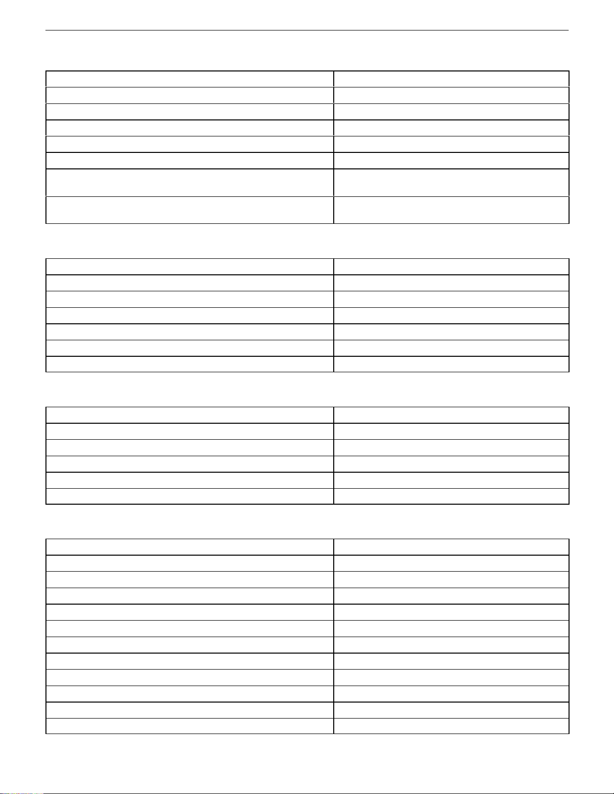
SPECIFICATIONS
TECHNICAL DATA
Performance – Manual Transaxle
AT LEAST MONTHLY 0B–12. . . . . . . . . . . . . . . . . . . . .
AT LEAST TWICE A YEAR 0B–12. . . . . . . . . . . . . . . .
EACH TIME THE OIL IS CHANGED 0B–13. . . . . . . .
AT LEAST ANNUALLY 0B–13. . . . . . . . . . . . . . . . . . . .
RECOMMENDED FLUIDS AND LUBRICANTS 0B–15
GENERAL DESCRIPTION AND SYSTEM
OPERATION 0B–16. . . . . . . . . . . . . . . . . . . . . . . . . . . . .
GENERAL REPAIR INSTRUCTIONS 0B–16. . . . . . .
GENERAL DESCRIPTION 0B–17. . . . . . . . . . . . . . . . . .
ON BOARD REFUELING VAPOR RECOVERY
SYSTEM 0B–17. . . . . . . . . . . . . . . . . . . . . . . . . . . . . .
VEHICLE IDENTIFICATION 0B–20. . . . . . . . . . . . . . .
VEHICLE LIFTING PROCEDURES 0B–24. . . . . . . . .
Application 2.0L DOHC
Maximum Speed 195 km/h (122 mph)
Gradeability 0.446 (tan Ø)
Minimum Turning Radius 5.3 m (17 ft)
Performance – Automatic Transaxle
Application 2.0L DOHC
Maximum Speed 190 km/h (119mph)
Gradeability 0.668 (tan Ø)
Minimum Turning Radius 5.3 m (17 ft)
Page 3
0B – 2IGENERAL INFORMATION
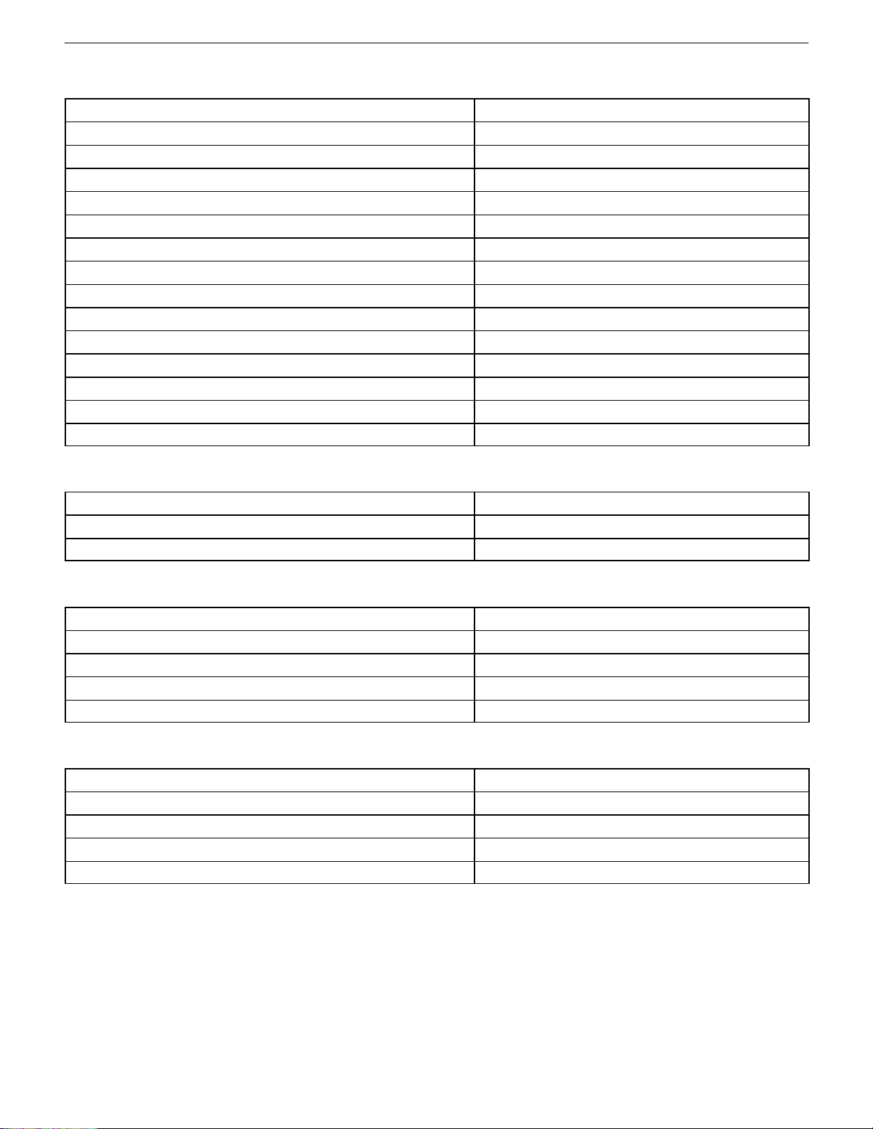
Engine
Application 2.0L DOHC
Engine Type Dual Overhead Cam L–4
Bore 86 mm (3.4 in.)
Stroke 86 mm (3.4 in.)
Total Displacement 1 998 cm3 (121.9 in3)
Compression Ratio 9.5µ0.2:1
Maximum Power 96 kW (128.7 bhp)
(at 5,400 rpm)
Maximum Torque 184 NSm (135.7 lb–ft)
(at 4,400 rpm)
Ignition System
Application 2.0L DOHC
Ignition Type Direct Ignition System
Ignition Timing 8³ BTDC
Ignition Sequence 1–3–4–2
Spark Plug Gap 0.8 mm (0.031 in)
Spark Plug Maker Bosch
Spark Plug Type FR8LDC4
Clutch – Manual Transaxle
Application 2.0L DOHC
Type Single Dry Plate
Outside Diameter 225 mm (9.0 in.)
Inside Diameter 150 mm (5.9 in.)
Thickness 3.4 mm (0.13 in.)
Fluid Capacity Common Use; Brake Fluid
Manual Transaxle
Application 2.2L DOHC
Maker DWMC
Type or Model D–20
Gear Ratio: –
1st 3.545:1
2nd 2.158:1
3rd 1.478:1
4th 1.129:1
5th 0.886:1
Reverse 3.333:1
Final Drive Ratio 3.550:1
Oil Capacity 1.8L (2 qt)
* Puerto Rico only.
DAEWOO V–121 BL4
Page 4

GENERAL INFORMATION 0B – 3
Automatic Transaxle
Application 2.0L DOHC
Maker GM
Type or Model 4T40E
Gear Ratio: –
1st 2.957:1
2nd 1.623:1
3rd 1.000:1
4th 0.682:1
Reverse 2.143:1
Final Drive Ratio 3.910:1
Oil Capacity 11.5L (12 qt)
Brake
Application 2.0L DOHC
Booster Size: –
Single 228.6 mm (9 in.)
Master Cylinder Diameter 22.2 mm (0.87 in.)
Booster Ratio 5.0:1
Front Brake: –
Disc Type Ventilated
Disc Size 356 mm (14.0 in.)
Rear Brake: –
Disc: –
Disc Type Solid
Disc Size 32 mm (1.3 in.)
Fluid Capacity 0.5L (0.53 qt)
Tire and Wheel
Application 2.0L DOHC
Standard Tire Size 185/65R14
Temporary Tire Size T125/70D15
Standard Wheel Size 5.5JX14
Inflation Pressure at Full Load: –
185/65R14: ––
Front 30 psi
Rear 28 psi
T127/70D15 60 psi
DAEWOO V–121 BL4
Page 5
0B – 4IGENERAL INFORMATION
Steering System
Application 2.0L DOHC
Gear Type Power Rack and Pinion
Overall Gear Ratio: –
Manual Steering –
Power Steering 16:1
Wheel Alignment: –
Front: –
Total Toe–In (2 Occupants) –10′ to +10′
Caster: –
Power Steering 2³30′ to 3³30′
Camber –54′ to 6′
Rear: –
Total Toe–In (2 Occupants) –3′ to +17′
Camber –1³35′ to –5′
Oil Capacity 1.0L (1.1 qt)
Suspension
Application 2.0L DOHC
Front Type MacPherson Strut
Rear Type Compound Link
Fuel System
Application 2.0L DOHC
Fuel Delivery MPI
Fuel Pump Type Electric Motor Pump
Fuel Filter Type Cartridge
Fuel Capacity 52L (13.7 gal)
Lubricating System
Application 2.0L DOHC
Lubricating Type Forced Feed
Oil Pump Type Duocentric Rotor
Oil Filter Type Cartridge (Full Flow)
Oil Pan Capacity Including Oil Filter 3.8L (4.1 qt)
DAEWOO V–121 BL4
Page 6

GENERAL INFORMATION 0B – 5
Cooling System
Application 2.0L DOHC
Cooling Type Forced Water Circulation
Radiator Type Cross–flow
Water Pump Type Centrifugal
Thermostat Type Pellet Type
Coolant Capacity: –
Manual: 7.0L (7.4 qt)
Automatic: 7.0L (7.4 qt)
Electric System
Application 2.0L DOHC
Battery (55 AH, M/F) 630 Cold Cranking Amps
Alternator: 85 Amps
Starter (1.4 kW) No Load Test Minimum 40 Amps
Maximum 90 Amps
(at 12.2 volts)
VEHICLE DIMENSIONS AND WEIGHTS
Vehicle Dimensions – Manual and Automatic
Application 2.0L DOHC
Overall Length: –
4–Door Notchback 4 470 mm (176.0 in.)
4–Door Wagon 4 514 mm (177.7 in.)
5–Door 4 248 mm (167.2 in.)
Overall Width 1 700 mm (66.9 in.)
Overall Height: –
4–Door Notchback 1 425 mm (56.1 in.)
4–Door Wagon 1 432 mm (56.4 in.)
5–Door 1 425 mm (56.1 in.)
Overall Height: Overall Height:
4–Door Notchback 1 430 mm (56.2 in.)
4–Door Wagon 1 470 mm (58.0 in.)
5–Door 1 430 mm (56.2 in.)
Minimum Ground Clearance 151 mm (5.9 in.)
Wheel Base 2 570 mm (101.2 in.)
Tread: –
Front 1 464 mm (57.6 in.)
Rear 1 454 mm (57.2 in.)
DAEWOO V–121 BL4
Page 7

0B – 6IGENERAL INFORMATION
Vehicle Weights – 4 Door Notchback
Application 2.0L DOHC
Manual: –
Curb Weight: –
Standard 1 164 kg (2,566 lb)
Optional 1 233 kg (2,718 lb)
Gross Vehicle Weight 1 720 kg (3,792 lb)
Automatic: –
Curb Weight –
Standard 1 200 kg (2,645 lb)
Optional 1 269 kg (2,797 lb)
Gross Vehicle Weight 1 720 kg (3,792 lb)
Passenger Capacity 5
Vehicle Weights – 4 Door Wagon
Application 2.0L DOHC
Manual: –
Curb Weight: –
Standard 1 222 kg (2,694 lb)
Optional 1 291 kg (2,846 lb)
Gross Vehicle Weight 1 860 kg (4,101 lb)
Automatic: –
Curb Weight –
Standard 1 258 kg (2,773 lb)
Optional 1 327 kg (2,925 lb)
Gross Vehicle Weight 1 860 kg (4,101 lb)
Passenger Capacity 5
Vehicle Weights – 5 Door
Application 2.0L DOHC
Manual: –
Curb Weight: –
Standard 1 155 kg (2,546 lb)
Optional 1 224 kg (2,698 lb)
Gross Vehicle Weight 1 720 kg (3,792 lb)
Automatic: –
Curb Weight: –
Standard 1 191 kg (2,625 lb)
Optional 1 260 kg (2,778 lb)
Gross Vehicle Weight 1 720 kg (3,792 lb)
Passenger Capacity 5
Optional Weight: Air Conditioning, Power Steering, ABS, Sunroof, Airbag.
DAEWOO V–121 BL4
Page 8
GENERAL INFORMATION 0B – 7
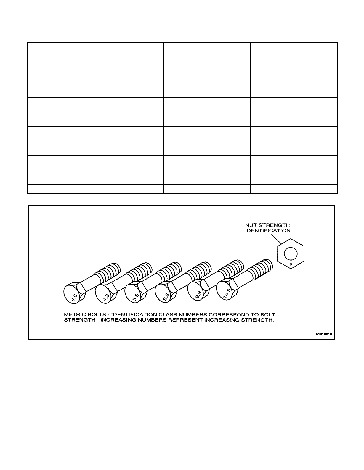
STANDARD BOLT SPECIFICATIONS
Bolt* 4T – Low Carbon Steel 7T – High Carbon Steel 7T – Alloy Steel
M6 X 1.0 4.1–8.1 NSm (36–72 lb–in) 5.4–9.5 NSm (48–84 lb–in) –
M8 X 1.25 8.1–17.6 NSm (72–156 lb–in) 12.2–23.0 NSm (108–204 lb–
in)
M10 X 1.25 20–34 NSm (15–25 lb–ft) 27–46 NSm (20–34 lb–ft) 37–62 NSm (27–46 lb–ft)
M10 X 1.5 19–34 NSm (14–25 lb–ft) 27–45 NSm (20–33 lb–ft) 37–60 NSm (27–44 lb–ft)
M12 X 1.25 49–73 NSm (36–54 lb–ft) 61–91 NSm (45–67 lb–ft) 76–114 NSm (56–84 lb–ft)
M12 X 1.75 45–69 NSm (33–51 lb–ft) 57–84 NSm (42–62 lb–ft) 72–107 NSm (53–79 lb–ft)
M14 X 1.5 76–115 NSm (56–85 lb–ft) 94–140 NSm (69–103 lb–ft) 114–171 NSm (84–126 lb–ft)
M14 X 2.0 72–107 NSm (53–79 lb–ft) 88–132 NSm (65–97 lb–ft) 107–160 NSm (79–118 lb–ft)
M16 X 1.5 104–157 NSm (77–116 lb–ft) 136–203 NSm (100–150 lb–ft) 160–240 NSm (118–177 lb–ft)
M16 X 2.0 100–149 NSm (74–110 lb–ft) 129–194 NSm (95–143 lb–ft) 153–229 NSm (113–169 lb–ft)
M18 X 1.5 151–225 NSm (111–166 lb–ft) 195–293 NSm (144–216 lb–ft) 229–346 NSm (169–255 lb–ft)
M20 X 1.5 206–311 NSm (152–229 lb–ft) 270–405 NSm (199–299 lb–ft) 317–476 NSm (234–351 lb–ft)
M22 X 1.5 251–414 NSm (185–305 lb–ft) 363–544 NSm (268–401 lb–ft) 424–636 NSm (313–469 lb–ft)
M24 X 2.0 359–540 NSm (265–398 lb–ft) 431–710 NSm (318–524 lb–ft) 555–831 NSm (409–613 lb–ft)
16–30 NSm (12–22 lb–ft)
* Diameter X pitch in millimeters
DAEWOO V–121 BL4
Page 9

0B – 8IGENERAL INFORMATION
MAINTENANCE AND REPAIR
MAINTENANCE AND LUBRICATION
NORMAL VEHICLE USE
The maintenance instructions contained in the maintenance schedule are based on the assumption that the vehicle will be used for the following reasons:
S To carry passengers and cargo within the limitation
indicated on the Tire Placard located on the edge of
the driver’s side door.
S To be driven on reasonable road surfaces and with-
in legal operating limits.
EXPLANATION OF SCHEDULED
MAINTENANCE SERVICES
The services listed in the maintenance schedule are further explained below. When the following maintenance
services are performed, make sure all the parts are replaced and all the necessary repairs are done before driving the vehicle. Always use the proper fluid and lubricants.
Drive Belt Inspection
When a separate belt drives the power steering pump, the
air conditioning compressor, and the generator, inspect it
for cracks, fraying, wear, and proper tension. Adjust or replace the belt, as needed.
Engine Oil and Oil Filter Change
API Classifications of Engine Oil
The International Lubricant Standardization and Approval
Committee (ILSAC) and American Petroleum Institute
classifies engine oils according to their performance quality. Always use oil rated API–SJ (ILSAC GF–II) or better.
Engine Oil Viscosity
Engine oil viscosity (thickness) has an effect on fuel economy and cold weather operation. Lower viscosity engine
oils can provide better fuel economy and cold weather performance; however, higher temperature weather conditions require higher viscosity engine oils for satisfactory lubrication. Using oils of any viscosity other than those
viscosities recommended could result in engine damage.
Cooling System Service
Drain, flush and refill the system with new coolant. Refer
to ”Recommended Fluids and Lubricants”in this section.
DAEWOO V–121 BL4
Page 10
GENERAL INFORMATION 0B – 9
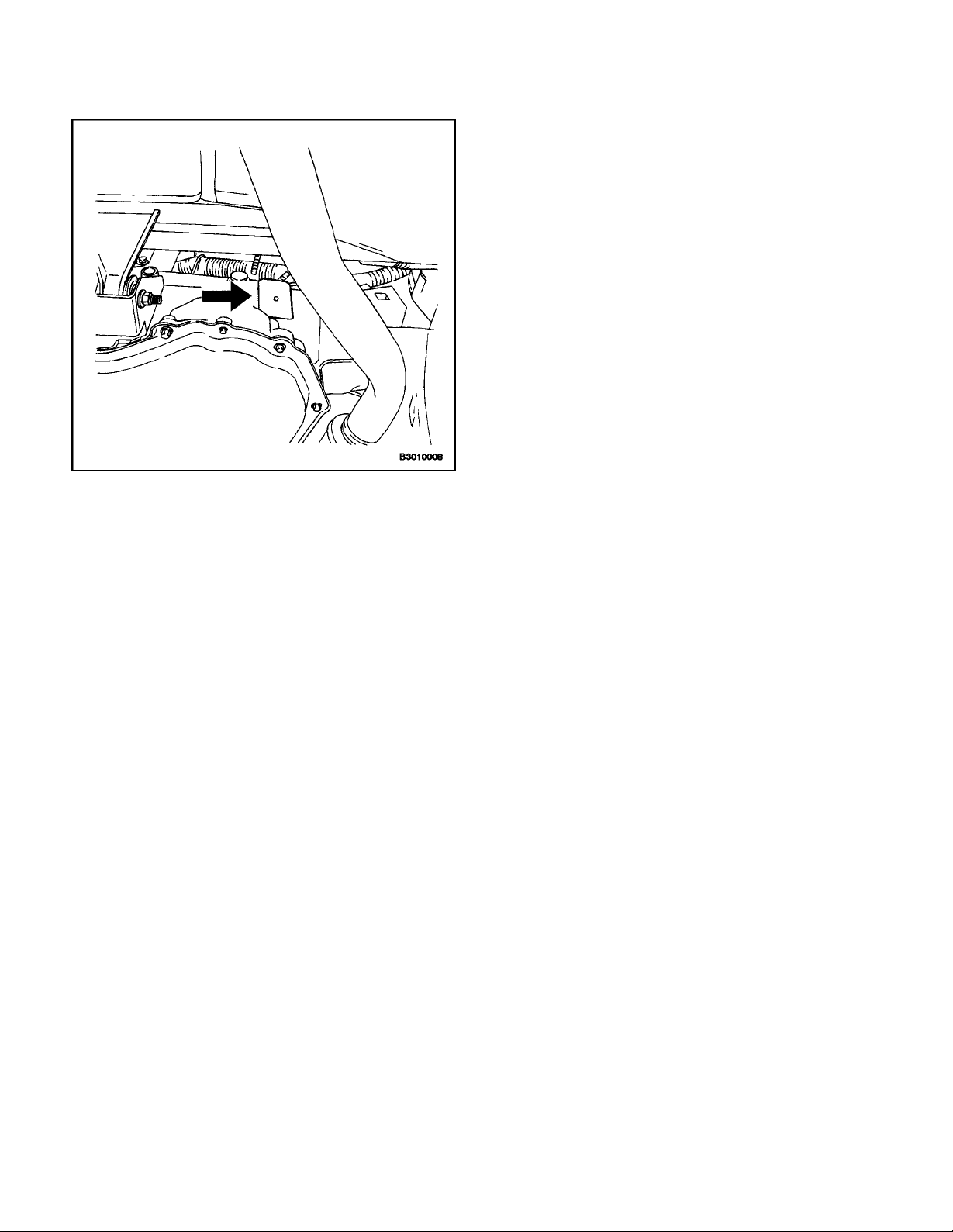
Fuel Micro–Filter Replacement
Replace the engine fuel filter every 48,000 km (30,000
miles).
The engine fuel filter is located on the center dash panel
near the brake booster.
Air Cleaner Element Replacement
Replace the air cleaner element every 48 000 km (30,000
miles).
Replace the air cleaner more often under dusty conditions.
Throttle Body Mounting Bolt Torque
Check the torque of the throttle body mounting bolts.
Tighten the throttle body mounting bolts to 17 NSm (13 lb–
ft) if necessary.
Spark Plug Replacement
Replace spark plugs with the same type.
– Type: AC Type FR8LDC4 (2.0L DOHC)
– Gap: 0.8 mm (0.031 in.) (2.0L DOHC)
Spark Plug Wire Replacement
Clean the w i res and inspect them for burns, cracks, or other damage. Check the wire boot fit at the direct ignition
system (DIS) module and at the spark plugs. Replace the
wires, as needed.
Brake System Service
Check the disc brake pads or the drum brake linings every
9,600 km (6,000 mi) or 6 months. Check the pad and the
lining thickness carefully. If the pads or the linings are not
expected to last another 9,600 km (6,000 mi), replace the
pads or the linings. Check the breather hole in the brake
fluid reservoir cap to be sure it is free from dirt and the passage is open.
Transaxle Service
The manual transaxle fluid does not require changing. For
automatic transaxles, refer to ”Scheduled Maintenance
Charts”in this section.
DAEWOO V–121 BL4
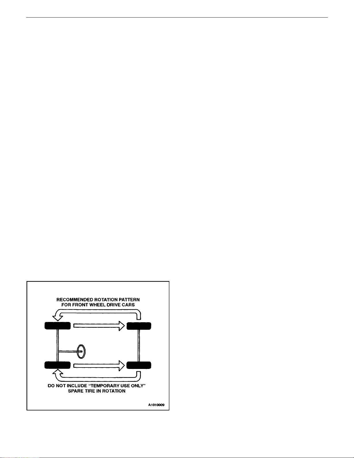
Tire and Wheel Inspection and Rotation
Check the tires for abnormal wear or damage. To equalize
wear and obtain maximum tire life, rotate the tires. If irregular or premature wear exists, check the wheel alignment
and check for damaged wheels. While the tires and
wheels are removed, inspect the brakes. Refer to ”Each
Time The Oil Is Changed”in this section.
Page 11
0B – 10IGENERAL INFORMATION
belt)
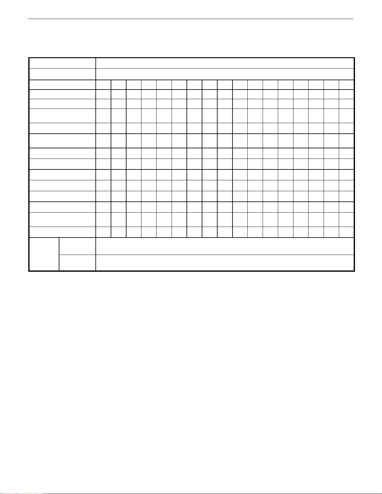
SCHEDULED MAINTENANCE CHARTS
Engine
Maintenance Item Maintenance Interval
Miles (Kilometers) or time inmonths, whichever comes first
x 1,000 miles
x 1,000 km
# Months
Drive belt (Generator and power
Steering)
Engine oil & engine oil filter (1)(3)
Cooling system hose & connections
Engine coolant (3)
Fuel filter
Fuel line and connections
Air cleaner element (2)
Ignition timing
Spark plugs
Evaporative emission canister &
vapor lines
PCV system
Camshaft
belt(Timimg
belt)
Out of Cali-
fornia
California
6 12 18 24 30 36 42 48 54 60 66 72 78 84 90 96 102
9.6 19.2 28.8 38.4 48 57.6 67.2 76.8 86.46 96 105.6 115.2 124.8 134.4 144 153.6 163.2
6 12 18 24 30 36 42 48 54 60 66 72 78 84 90 96 102
I I I I I
R R R R R R R R R R R R R R R R R
I I I I I I I I
I I I I R I I I I R I I I I R I I
R* R* R*
I* I* I* I* I* I* I* I*
I* I* I* I* R I* I* I* I* R I* I* I* I* R I* I*
I* I* I* I* I* I* I* I*
I* R I* R I* R
I* I* I*
I* I* I* I* I*
Replace every 72,000 miles (115,200 km)
Inspect every 60,000 miles (96,000 km) and 90,000 miles (144,000 km)
Replace every 102,000 miles (163,200 km)
Chart Symbols:
I – Inspect these items and their related parts. If necessary, correct, clean, replenish, adjust or replace.
R – Replace or change.
(1) Change the engine oil every 3,000 miles (4,800 kilometers) or 3 months, whichever comes first, if the vehicle is operated
under any of the following conditions :
– Short–distance driving.
– Extensive idling.
– Driving on dusty roads.
(2) More frequent maintenance is required if driving under dusty conditions.
(3) Refer to ”Recommended Fluids And Lubricants”
Note : Check the engine oil and radiator coolant levels every week.
* : Replacement or inspection of these emissions components is recommended to be performed at the indicated intervals
however, the California Air Resources Board has determined that performing thesemaintenance items are not required
to maintained your vehicle emission warranty.
DAEWOO V–121 BL4
Page 12

GENERAL INFORMATION 0B – 11
Chassis and Body
Maintenance Item Maintenance Interval
Miles (Kilometers) or time inmonths, whichever comes first
x 1,000 miles
x 1,000 km
# Months
Air Filter (A/C) (2)
Exhaust pipes & mountings
Brake/Clutch fluid (3)(5)
Brake pads & discs(6)
Parking brake
Brake line & connections (In-
cluding booster)
Rear hub bearing & clearance
Manual Transaxle Oil (3)
Clutch & brake pedal free play
Automatic transaxle fluid* (3) (7)
Chassis & underbody bolts &
nuts, tighten/secure
Tire condition & inflation pres-
sure
Wheel alignment (8)
Tire rotation
Steering wheel & linkage
Power steering fluid & lines*
Drive shaft boots
Seat belts, buckles & anchors
Lubricate locks, hinges & hood
latch
6 12 18 24 30 36 42 48 54 60 66 72 78 84 90 96 102
9.6 19.2 28.8 38.4 48 57.6 67.2 76.8 86.46 96 105.6 115.2 124.8 134.4 144 153.6 163.2
6 12 18 24 30 36 42 48 54 60 66 72 78 84 90 96 102
R R R R R R R R R R R R R R R R R
I* I* I* I* I* I* I* I*
I I R I I R I I R I I R I I R I
I I I I I I I I I I I I I I I I
I I I I I I I
I I I I I I I I I I I I I I I I
I I I I I I I I
I I I I I I I I
I I I I I I I I I I I I I I I I I
I I I I R I I I
I I I I I I I I I I I I I I I I I
I I I I I I I I I I I I I I I I I
Inspect when abnormal condition is noted.
Rotate tires every 6,000 miles
I I I I I I I I I I I I I I I I I
I I I I I I I I
I I I I I I I I I I I I I I I I I
I I I I I I I I I I I I I I I I I
I I I I I I I I
Chart Symbols:
I – Inspect these items and their related parts. If necessary, correct, clean, replenish, adjust or replace.
R – Replace or change.
(2) More frequent maintenance is required if driving under dusty conditions.
(3) Refer to”Recommended Fluids And Lubricants.”
(5) Change the brake/clutch fluid every 9,000 miles (14,400 kilometers) or 9months, whichever comes first, if the vehicle
is operated under any of the following conditions :
– Driving in hilly or mountainous terrain.
(6) More frequent maintenance is required if the vehicle is operated under any of the following conditions:
– Short–distance driving.
– Extensive idling or slow–speed driving in stop–and–go traffic.
– Driving on dusty roads.
(7) Change the automatic transaxle fluid every 50,000miles (80,000 kilometers) if the vehicle is operated under any of the
following conditions :
– Driving in hilly or mountainous terrain.
– Driving in heavy city traffic where the outside temperatures regularly reach 32³C (90³F) or higher.
– Driving a taxi, or police or delivery vehicles.
(8) If necessary, rotate and balance the wheels
Note : Check the engine oil and radiator coolant levels every week.
DAEWOO V–121 BL4
Page 13

0B – 12IGENERAL INFORMATION
* Replacement or inspection of these emissions components is recommended to be performed at the indicated intervals
however, the California Air Resources Board has determined that performing thesemaintenance items are not required
to maintained your vehicle emission warranty.
5. Add oil, if needed, to keep the oil level above the
OWNER INSPECTIONS AND
SERVICES
WHILE OPERATING THE VEHICLE
Horn Operation
Blow the horn occasionally to make sure it works. Check
all the button locations.
Brake System Operation
Be alert for abnormal sounds, increased brake pedal travel, or repeated pulling to one side when braking. Also, if the
brake warning light goes on or flashes, something may be
wrong with part of the brake system.
MIN line and within the area labeled ”Operating
Range.” Avoid overfilling the engine, since this may
cause engine damage.
6. Push the indicator all the way back down into the
engine after taking the reading.
If checking the oil level when the oil is cold, do not run the
engine first. The cold oil will not drain back to the pan fast
enough to give a true oil level reading.
Engine Coolant Level and Condition
Check the coolant level in the coolant reservoir tank and
add coolant, if necessary. Inspect the coolant. Replace
dirty or rusty coolant.
Windshield Washer Fluid Level
Check the washer fluid level in the reservoir. Add fluid, if
necessary.
Exhaust System Operation
Be alert to any changes in the sound of the system or the
smell of the fumes. These are signs that the system may
be leaking or overheating. Have the system inspected and
repaired immediately.
Tires,Wheels and Alignment Operation
Be alert to any vibration of the steering wheel or the seats
at normal highway speeds. This may mean a wheel needs
to be balanced. Also, a pull to the right or the left on a
straight, level road may show the need for a tire pressure
adjustment or a wheel alignment.
Steering System Operation
Be alert to changes in the steering action. An inspection
is needed when the steering wheel is hard to turn, has too
much free play, or if unusual sounds are noticed when
turning or parking.
Headlamp Aim
Take note of the light pattern occasionally. Adjust the
headlamps if the beams seem improperly aimed.
AT EACH FUEL FILL
A fluid loss in any (except windshield washer) system may
indicate a problem. Have the system inspected and repaired immediately.
Engine Oil Level
Check the oil level and add oil, if necessary. The best time
to check the engine oil level is when the oil is warm.
1. After stopping the engine, wait a few minutes for
the oil to drain back to the oil pan.
2. Pull out the oil level indicator (dipstick).
3. Wipe it clean, and push the oil level indicator back
down all the way.
4. Pull out the oil level indicator and look at the oil level on it.
AT LEAST MONTHLY
Tire and Wheel Inspection and Pressure
Check
Check the tires for abnormal wear or damage. Also, check
for damaged wheels. Check the tire pressure when the
tires are cold (check the spare tire, unless it is a stowaway). Maintain the recommended pressures that are on
the tire placard that is on the driver’s side door.
Lamp Operation
Check the operation of the license plate lamp, the headlamps (including the high beams), the parking lamps, the
fog lamps, the taillamp, the brake lamps, the turn signals,
the backup lamps, and the hazardwarning flasher.
Fluid Leak Check
Periodically inspect the surface beneath the vehicle for
water, oil, fuel or other fluids, after the vehicle has been
parked for a while. W ater dripping from the air conditioning
system after use is normal. If you notice fuel leaks or
fumes, find the cause and correct it immediately.
AT LEAST TWICE A YEAR
Power Steering System Reservoir Level
Check the power steering fluid level. Keep the power
steering fluid at the proper level. Refer to Section 6A, Pow-
er Steering System.
Brake Master Cylinder Reservoir Level
Check the fluid and keep it at the proper level. A low fluid
level can indicate worn disc brake pads andmay need to
be serviced. Check the breather hole in the reservoir cover
that it is free from dirt and check for an open passage.
Clutch Pedal Free Travel
Check clutch pedal free travel and adjust, as necessary,
every 16,000 km (10,000 miles). Measure the distance
from the center of the clutch pedal to the outer edge of the
DAEWOO V–121 BL4
Page 14

GENERAL INFORMATION 0B – 13
steering wheel with the clutch pedal not pressed. Then,
measure the distance from the center of the clutch pedal
to the outer edge of the steering wheel with the clutch pedal fully pressed. The difference between the two values
must be greater than 130 mm (5.1 in.).
Weatherstrip Lubrication
Apply a thin film of silicone grease using a clean cloth.
EACH TIME THE OIL IS CHANGED
Automatic Transaxle Fluid
Refer to”Transaxle Fluid Level Checking Procedure”in-
Section 5A, 4T40E Automatic Transaxle.
Manual Transaxle
Check the fluid level and add fluid, as required. Refer
toSection 5B, Five–Speed Manual Transaxle.
Brake System Inspection
This inspection should be done when the wheels are removed for rotation. Inspect the lines and the hoses for
proper hookup, binding, leaks, cracks, chafing, etc. Inspect the disc brake pads for wear. Inspect the rotors for
surface condition. Also, inspect the drum brake linings for
wear and cracks. Inspect other brake parts, including the
drums, the wheels cylinders, the parking brake, etc., at the
same time. Check the parking brake adjustment. Inspect
the brakes more often if habit or conditions result in frequent braking.
Steering, Suspension and Front Drive Axle
Boot and Seal Inspection
Inspect the front and the rear suspension and the steering
system for damaged, loose, or missing parts; signs of
wear; or lack of lubrication. Inspect the power steering
lines and the hoses for proper hookup, binding, leaks,
cracks and chafing, etc. Clean and inspect the drive axle
boot and seals for damage, tears, or leakage. Replace the
seals, if necessary.
Exhaust System Inspection
Inspect the complete system (including the catalytic converter, if equipped). Inspect the body near the exhaust
system. Look for broken, damaged, missing, or out of
position parts, as well as open seams, holes, loose connections, or other conditions which could cause heat buildup in the floor pan or could let exhaust fumes seep into the
trunk or passenger compartment.
Throttle Linkage Inspection
Inspect the throttle linkage for interference or binding,
damaged or missing parts. Lubricate all linkage joints and
throttle cable joints, the intermediate throttle shaft bearing,
the return spring at the throttle valve assembly , and the accelerator pedal sliding face with suitable grease. Check
the throttle cable for free movement.
Engine Drive Belts
Inspect all belts for cracks, fraying, wear, and proper tension. Adjust or replace the belts, as needed.
Hood Latch Operation
When opening the hood, note the operation of the secondary latch. It should keep the hood from opening all the
way when the primary latch is released. The hood must
close firmly.
AT LEAST ANNUALLY
Lap and Shoulder Belt Condition and
Operation
Inspect the belt system, including the webbing, the
buckles, the latch plates, the retractor, the guide loops and
the anchors.
Movable Head Restraint Operation
On vehicles with movable head restraints, the restraints
must stay in the desired position.
Spare Tire and Jack Storage
Be alert to rattles in the rear of the vehicle. The spare tire,
all the jacking equipment, and the tools must be securely
stowed at all times. Oil the jack ratchet or the screw mechanism after each use.
Key Lock Service
Lubricate the key lock cylinder.
Body Lubrication Service
Lubricate all the body door hinges including the hood, the
fuel door, the rear compartment hinges and the latches,
the glove box and the console doors, and any folding seat
hardware.
Transaxle Neutral Switch Operation on
Automatic Transaxle
CAUTION : Adhere to the following precautions. Failuretodosocancauseinjuriesandpropertydamage.
S Firmly apply the parking brake and the regular
brakes.
S Do not use the accelerator pedal.
S Be ready to turn the ignition OFF if the vehicle
starts.
On automatic transaxle vehicles, try to start the engine in
each gear. The starter should crank only in P (PARK) and
in N (NEUTRAL).
Parking Brake and Transaxle P (PARK)
Mechanism Operation
CAUTION : To reduce the risk of personal injury or
property damage, be prepared to apply the regular
brakes if the vehicle begins to move.
Park on a fairly steep hillwith enough roomformovement
in the downhill direction. To check the parking brake, with
the engine running and the transaxle in N (NEUTRAL),
slowly remove foot pressure fromthe regular brake pedal
(until only the parking brake is holding the vehicle).
To check the automatic transaxle P (PARK) mechanism’s
holding ability, release all brakes after shifting the transaxle to P (PARK).
DAEWOO V–121 BL4
Page 15

0B – 14IGENERAL INFORMATION
Underbody Flushing
Flushing the underbody will remove any corrosive materials used for ice and snow removal and dust control. At
least every spring, clean the underbody. First, loosen the
sediment packed in closed areas of the vehicle. Then,
flush the underbodywith plainwater.
Engine Cooling System
Inspect the coolant and freeze protection fluid. If the fluid
is dirty or rusty, drain, flush and refill the engine cooling
system with new coolant. Keep the coolant at the proper
mixture to ensure proper freeze protection, corrosion
protection and engine operating temperature. Inspect the
hoses. Replace the cracked, swollen, or deteriorated
hoses. Tighten the clamps. Clean the outside of the radiator and the air conditioning condenser. Wash the filler cap
and the neck. Pressure test the cooling system and the
cap to help ensure proper operation.
DAEWOO V–121 BL4
Page 16

GENERAL INFORMATION 0B – 15
RECOMMENDED FLUIDS AND LUBRICANTS
USAGE CAPACITY FLUID/LUBRICANT
Engine Oil 3.8L (4.1 qt) ILSAC GF–II (API SJ) grade
SAE 5W––30, SAE 10W––30
Engine Coolant 7.0L (7.4 qt) Mixture of water and good quality ethylene glycol–
base antifreeze (year–round coolant)
Brake and Clutch Fluid 0.5L (0.5 qt) SSK–221 (DOT–3 and DOT–4 Fluid)
Power Steering System Fluid 1.0L (1.1 qt) DEXRON±–III, DEXRON± II–D
Automatic Transaxle 11.5L (12.2 qt) DEXRON±–III
Manual Transaxle 1.8L (2 qt) Manual Transaxle Fluid ( B0400075, SAE80 or eqi-
valent; Extremely cold area: SAE 75W)
Manual Transaxle Shift Linkage As needed Multipurpose–type grease meeting requirements
NLGI No. 1 or 2
Key Lock Cylinders As needed Silicone lubricant
Automatic Transaxle Shift Link-
age
Clutch Linkage Pivot Points As needed Engine oil
Floor Shift Linkage Points As needed Engine oil
Hood Latch Assembly
1. Pivots and Spring Anchor
2. Release Pawl
Hood and door hinges
Fuel door hinge
Rear compartment lid hinges
Weatherstripping As needed Silicone grease
As needed Engine oil
As needed
As needed Engine oil
1. Engine oil
2. Multipurpose–type grease meeting requirements NLGI No. 1 or 2
DAEWOO V–121 BL4
Page 17

0B – 16IGENERAL INFORMATION
GENERAL DESCRIPTION
AND SYSTEM OPERATION
GENERAL REPAIR INSTRUCTIONS
If a floor jack is used, the following precautions are recommended:
S Park the vehicle on level ground, ”block” the front or
rear wheels, set the jack against the frame, raise
the vehicle and support it with chassis stands, and
then perform the service operation.
S Before performing the service operation, disconnect
the negative battery cable to reduce the chance of
cable damage and burning due to short–circuiting.
S Use a cover on the body, the seats, and the floor to
protect them against damage and contamination.
S Handle brake fluid and antifreeze solution with care
as they can cause paint damage.
S The use of proper tools, and the required special
tools where specified, is important for efficient and
reliable performance of the service repairs.
S Use genuine DAEWOO parts.
S Discard used cotter pins, gaskets, O–rings, oil
seals, lock washers and self–locking nuts. Prepare
new ones for installation. Normal functioning of the
vehicle’s components cannot be maintained if these
fasteners and seals are reused.
S Keep the disassembled parts to assist in reassemb-
ly.
S Keep attaching bolts and nuts separated, as they
vary in hardness and design depending on the position of the installation.
S Clean the parts before inspection or reassembly.
S Clean the oil parts, etc. Use compressed air to
make certain they are free of restrictions.
S Lubricate rotating and sliding faces of parts with oil
or grease before installation.
S When necessary, use a sealer on gaskets to pre-
vent leakage.
S Carefully observe all specifications for bolt and nut
torques.
When service operation is complete, make a final check
to be sure service was done properly and the problem was
corrected.
DAEWOO V–121 BL4
Page 18

GENERAL INFORMATION 0B – 17
GENERAL DESCRIPTION
ON BOARD REFUELING VAPOR
RECOVERY SYSTEM
The NUBIRA 2.0 DOHC model is equipped with an On
Board Diagnostic Stage II (OBD–II) system to meet enhanced emission control requirements. Within this OBD–II
system, an On Board Refueling Vapor Recorvery (ORVR)
system has been developed and equipped to meet enhanced evaporative emission control requirements during
vehicle moving, parking, and refueling at gas stations. The
Daewoo ORVR system adopts one canister to collect both
evaporative vapors during the moving & parking as well as
refueling vapor. Collected vapor is consurmed by the engine through the intake manfold during vehicle operation.
The mechanism of Daewoo ORVR system to meet the
ORVR requirement is to create suction inside filler neck by
the aid of fuel flow through a reduced diameter section in
the filler pipe.
Therefore, Daewoo ORVR system adopts the so called
”Liquid Trap” or ”Liquid Seal” system that assures the long
term durability.
The Daewoo ORVR system provides nozzle compatibility
with conventional and stage II vapor recovery nozzle.
The Daewoo ORVR system has been designed to have
the following functional features.
S To collect refueling vapors and to route to canister.
S To provide nozzle compatibility with conventional
and stage II vapor recovery nozzles.
S To provide fill shut off signal.
S To prevent canister from liquid fuel during normal
driving and vehicle rollover.
S To provide fuel tank venting to canister during ve-
hicle operation.
S To protect fuel tank from over–pressure.
S To protect fuel vapor dome from overfill.
Any failures or malfunction of the ORVR system will be
identified by OBD–II system and warned through Malfunction Indicator Lamp (MIL) on the instrument cluster.
No special refueling procedures and mainternance on
ORVR system are required.
The Daewoo ORVR system and all fuel system components have been designed to prevent the electrostatic discharge phenomenon by adopting mitigation techniques
recommended in SAE J1645. Daewoo’s own test procedure (EDS–T–5005) is similar to SAE J1113.
DAEWOO V–121 BL4
Page 19
0B – 18IGENERAL INFORMATION
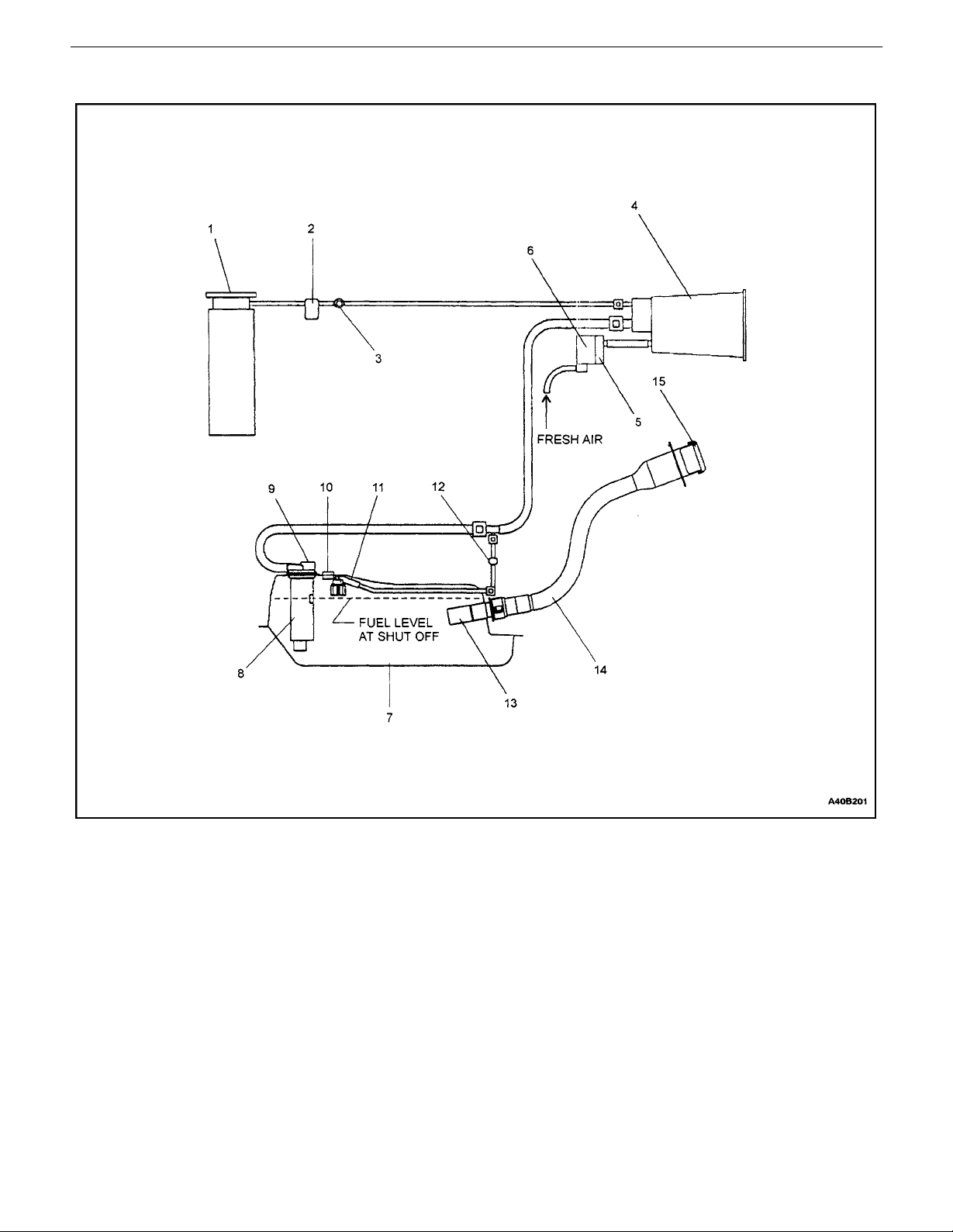
Schematic Of On Board Refueling Vapor Recovery System
1. Manifold (Intake)
2. Canister Purge Valve (Electronic Pwm Control)
3. Service Port
4. Integrated Fuel Vapor Storage Canister
5. OBD–II Valve (Solenoid)OBD–II Valve (Solenoid)
6. Air Filter
7. Fuel Tank (Steel)
8. Fuel Fill Vent Control Valve & Liquid–Vapor Dis-
criminator
9. Pressure Relief Valve
10. Tank Pressure Transducer (OBD–II)
11. Rollover Valve
12. 2–Way Check Valve
13. Check Valve
14. Fuel Filler Tube (Dynamic Seal During Fill)
15. Fuel Filler Cap (Pressure–Vacuum Relief)
DAEWOO V–121 BL4
Page 20
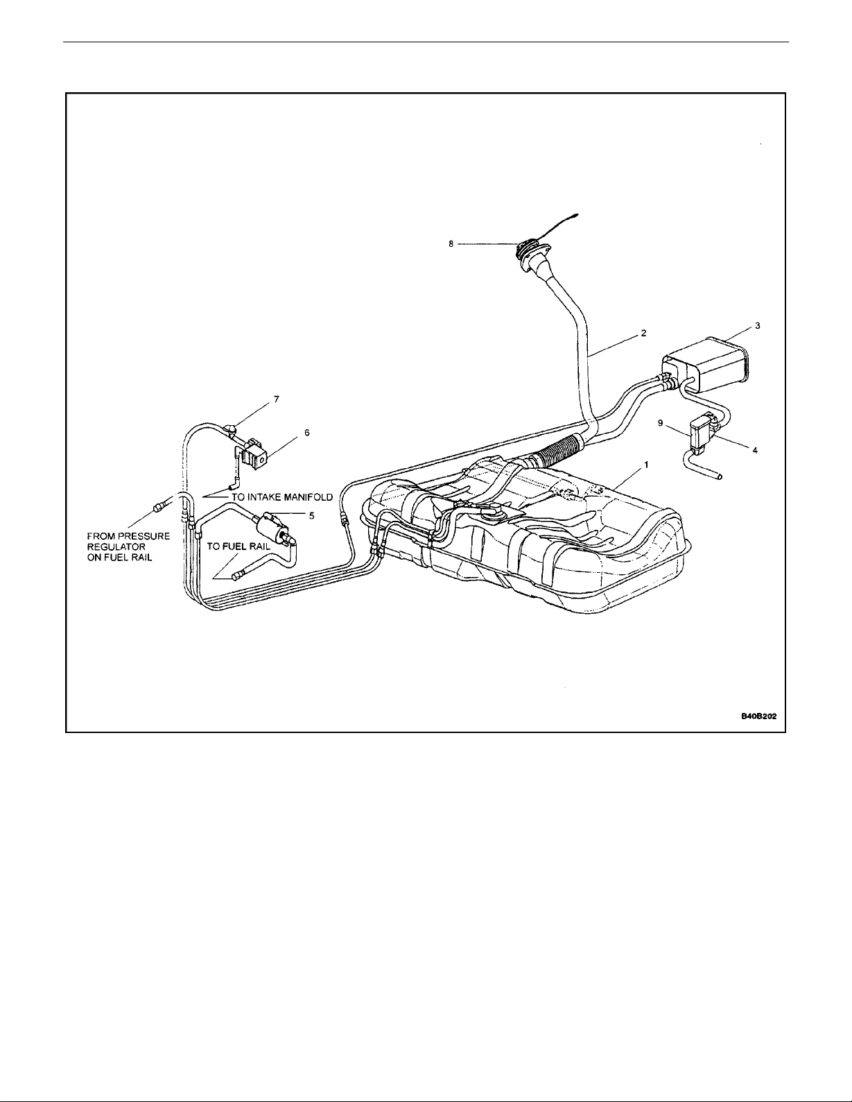
Component Locator
GENERAL INFORMATION 0B – 19
1. Fuel Tank
2. Filler Tube
3. Canister
4. OBD– II Valve
5. Fuel Filter
DAEWOO V–121 BL4
6. Purge Valve
7. Service port
8. Fuel Filler Cap
9. Air Filter
Page 21
0B – 20IGENERAL INFORMATION
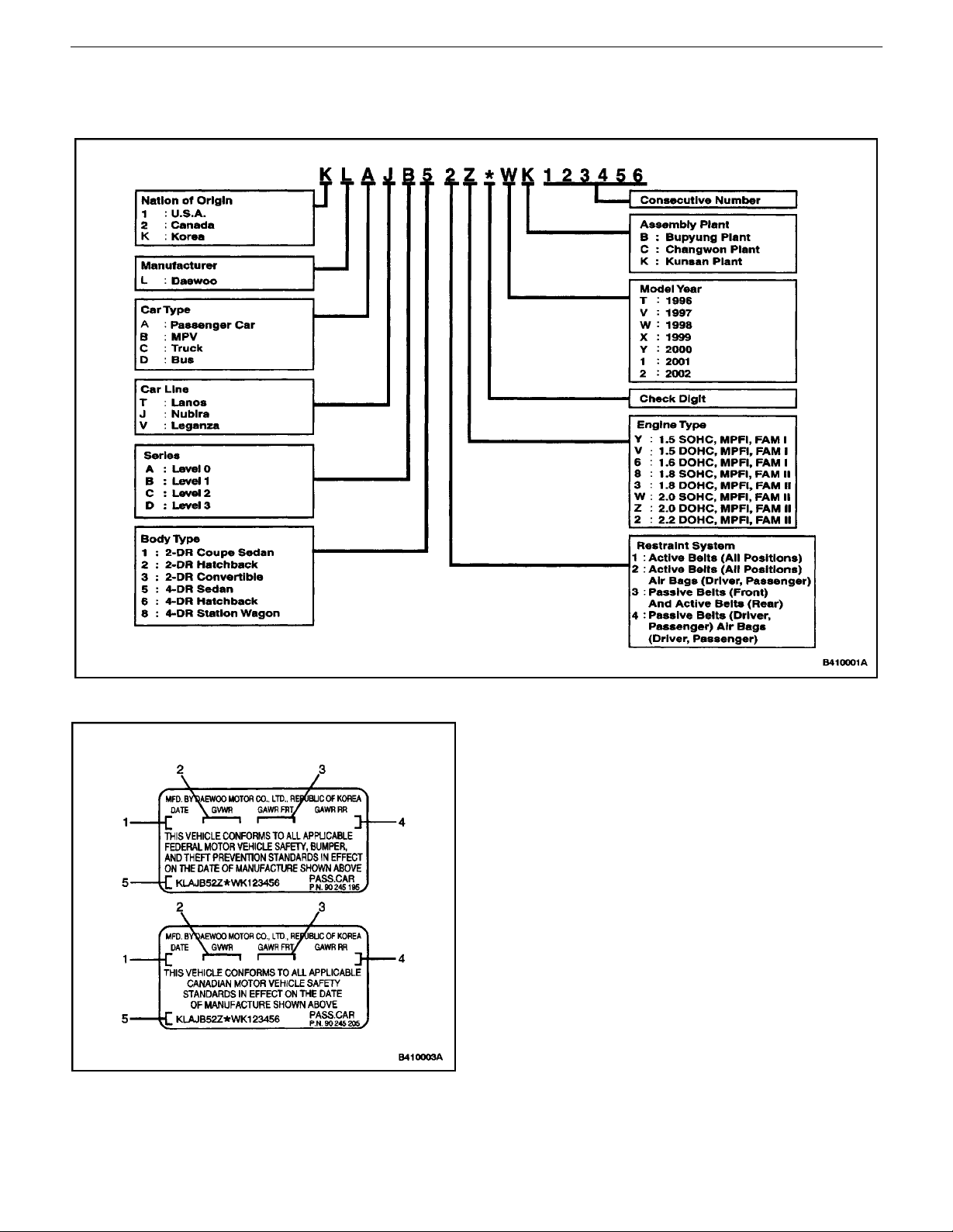
VEHICLE IDENTIFICATION
Passenger Car VIN
Certification plate
1. Production Date
2. Gross Vehicle Weight Rating
3. Gross Axle Weight Rating Front
4. Gross Axle Weight Rating Rear
5. Vehicle Identification Number
DAEWOO V–121 BL4
Page 22
GENERAL INFORMATION 0B – 21
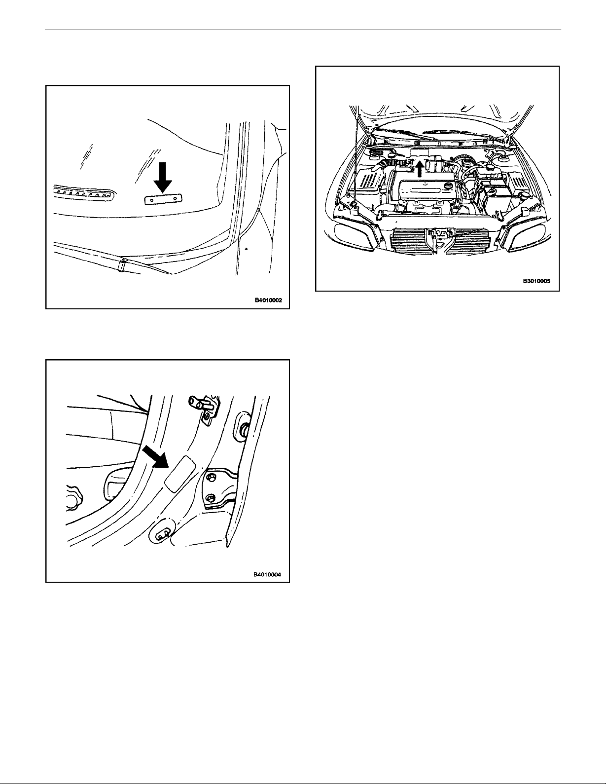
VIN Plate Location
The vehicle identification number (VIN) plate is attached
to the top of the driver’s side of the instrument panel.
Certification Label
The Certification Label is attached to the driver’s side B–
pillar near door strike.
Engraved VIN Location
The vehicle identification number (VIN) is engraved in the
top of the bulkhead, next to the ABS module.
DAEWOO V–121 BL4
Page 23
0B – 22IGENERAL INFORMATION
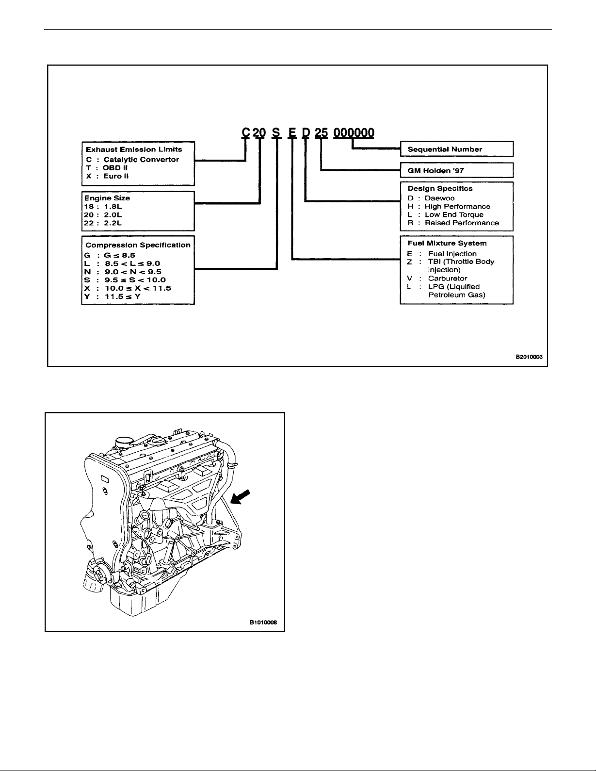
Engine Number – Family II (2.0L DOHC Engine)
Engine Number Plate Location – Family II
(2.0L DOHC Engine)
The engine number is stamped on the cylinder block under
the No. 4 exhaust manifold of the engine.
DAEWOO V–121 BL4
Page 24
GENERAL INFORMATION 0B – 23
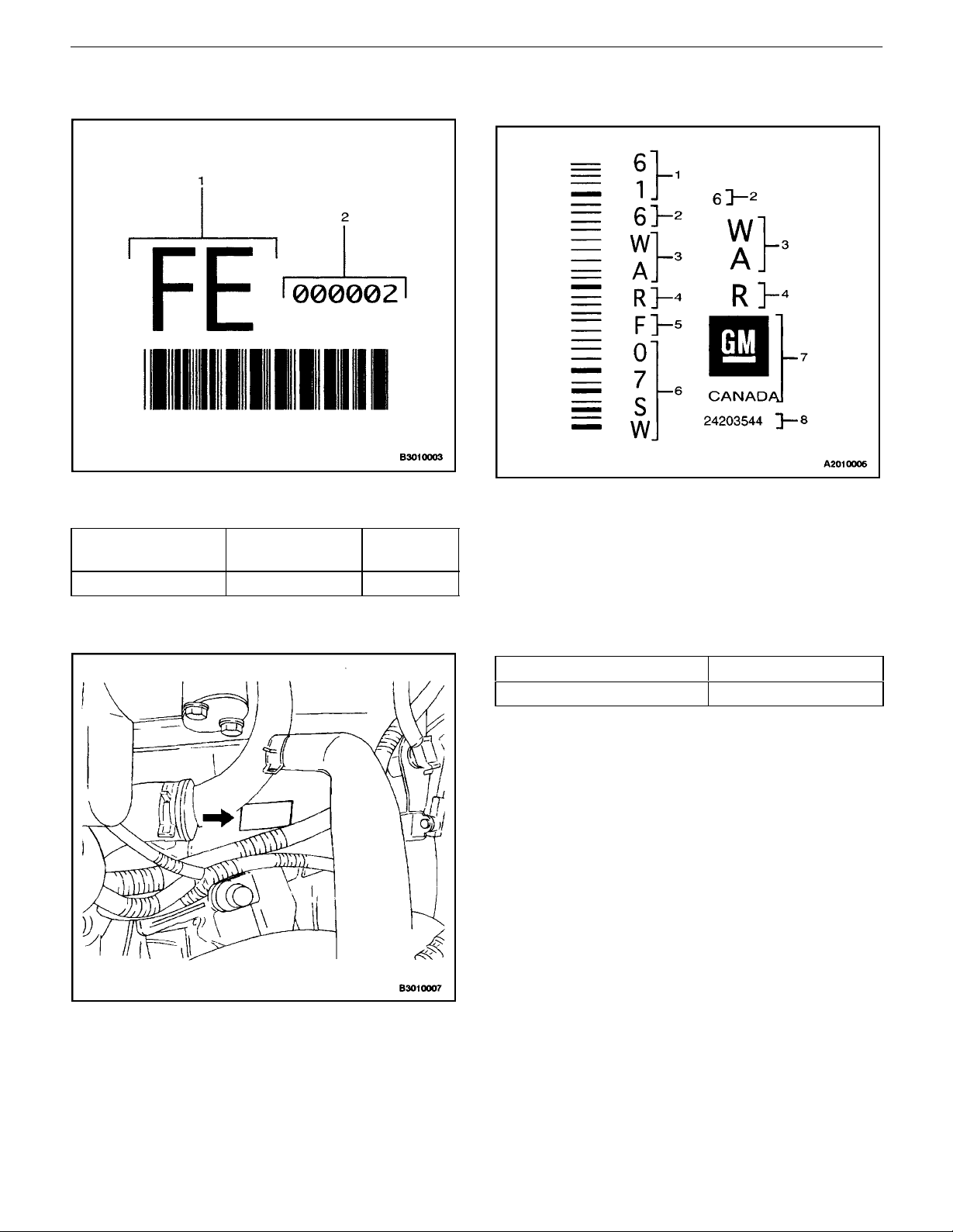
Manual Transaxle Identification Number
Plate
1. Identification Code
2. Sequential Number
Identification
Code
FE 2.0L DOHC 3.545 C/R
Engine Gear Ratio
Manual Transaxle Identification Number
Plate Location
Automatic Transaxle Identification Number
Plate
1. Assembly Plant (Windsor, Canada)
2. Model Year (1996)
3. Broadcast Code
4. Model Name (4T40E)
5. Update Level
6. Sequential Number
7. Manufacturer
8. Part Number
The manual transaxle identification number is attached to
the top of the transaxle case near the engine.
Identification Code Engine
7ZZR 2.0L DOHC
DAEWOO V–121 BL4
Page 25
0B – 24IGENERAL INFORMATION
Automatic Transaxle Identification Number
Plate Location
The automatic transaxle identification number plate is attached on the rear side of the transaxle near the bulkhead.
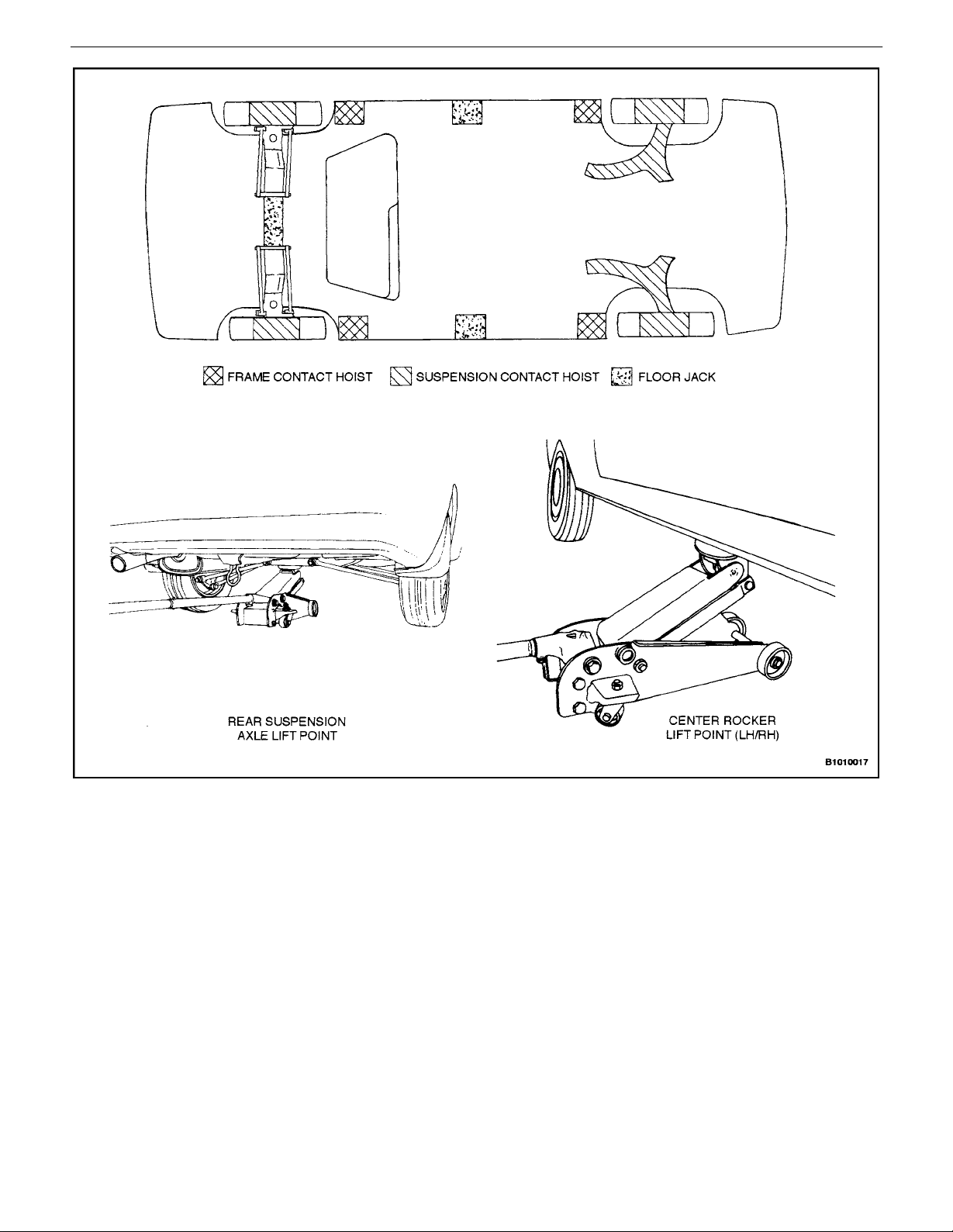
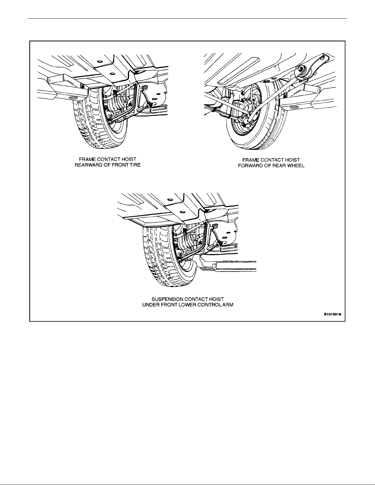
VEHICLE LIFTING PROCEDURES
Notice : To raise the vehicle, place the lifting equipment
only at the points indicated. Failure to use these precise
positions may result in permanent body deformation.
Many dealer service facilities and service stations are
equipped with automotive hoists that bear upon some
parts of the frame to lift the vehicle. If any other hoist method is used, use special care to avoid damaging the fuel
tank, the filler neck, the exhaust system, or the underbody .
DAEWOO V–121 BL4
Page 26
GENERAL INFORMATION 0B – 25
DAEWOO V–121 BL4
Page 27
0B – 26IGENERAL INFORMATION
Vehicle Lifting Points
DAEWOO V–121 BL4
Page 28

SECTION : 1A
GENERAL ENGINE INFORMATION
TABLE OF CONTENTS
DIAGNOSIS 1A–1. . . . . . . . . . . . . . . . . . . . . . . . . . . . . . . .
COMPRESSION TEST 1A–1. . . . . . . . . . . . . . . . . . . . .
OIL PRESSURE TEST 1A–2. . . . . . . . . . . . . . . . . . . . .
OIL LEAK DIAGNOSIS 1A–3. . . . . . . . . . . . . . . . . . . . .
KNOCK DIAGNOSIS 1A–4. . . . . . . . . . . . . . . . . . . . . . .
DIAGNOSIS
COMPRESSION TEST
Important : Disconnect the Crankshaft Position Sensor
(CPS) connector to disable the fuel and the ignition systems.
Test the compression pressure for each cylinder. Low
compression pressure may be the fault of the valves or the
pistons. The following conditions should be considered
when checking the cylinder compression:
S The engine should be at normal operating tempera-
ture.
S The throttle must be wide open.
S All the spark plugs should be removed.
S The battery must be at or near full charge.
1. Place approximately three squirts of oil from a
plunger type oiler into each spark plug port.
2. Insert the engine compression gauge into each
spark plug port.
NOISE DIAGNOSIS 1A–8. . . . . . . . . . . . . . . . . . . . . . .
GENERAL INFORMATION 1A–11. . . . . . . . . . . . . . . . . .
CLEANLINESS AND CARE 1A–11. . . . . . . . . . . . . . . .
ON–ENGINE SERVICE 1A–11. . . . . . . . . . . . . . . . . . .
3. Crank test each cylinder with four to five compression strokes using the starter motor.
4. The lowest reading should not be less than 70% of
the highest reading. The compression gauge reading should not be less than 689 kPa (100 psi) for
any of the cylinders.
5. Examine the gauge readings obtained after the four
”puffs” per cylinder are obtained from cranking the
starter motor. The readings are explained in the
following descriptions:
S Normal Condition – Compression builds up quickly
and evenly to specified compression on each cylinder.
S Piston Rings Faulty – Compression is low on the
first stroke and tends to build up on following
strokes, but does not reach normal. The compression pressure improves considerably with the addition of oil into the cylinder.
S Valves Faulty – Low compression pressure on the
first stroke. The compression pressure does not
tend to build up on the following strokes. The compression pressure does not improve much with the
addition of oil into the cylinder.
Page 29

1A – 2IGENERAL ENGINE INFORMATION
OIL PRESSURE TEST
Step Action Value(s) Yes No
1 Is the oil pressure warning lamp on? Go to Step 2 System OK
2 Check the oil level in the crankcase.
Is the oil level low?
3 Add oil so that the oil level is up to the MAX mark on
the indicator.
Is the repair complete?
4 Check the idle speed.
Is the idle speed below the value specified?
5 Increase the idle speed.
Is the speed increased?
6 Inspect the oil pressure switch.
Is the oil pressure switch incorrect or malfunctioning?
7 Install a new oil pressure switch.
Is the repair complete?
8 Inspect the oil pressure gauge.
Is the oil pressure gauge incorrect or malfunctioning?
9 Install a new oil pressure gauge.
Is the repair complete?
10 Inspect the engine oil.
Is the engine oil in the crankcase diluted or of the improper viscosity?
11 Install new engine oil of the proper viscosity for the
expected temperatures.
Is the repair complete?
12 Inspect the oil pump.
Is the pump worn or dirty?
13 Replace the oil pump.
Is the repair complete?
14 Inspect the oil filter.
Is the oil filter plugged?
15 Install a new oil filter.
Is the repair complete?
16 Inspect the oil pickup screen.
Is the oil pickup screen loose or plugged?
17 Tighten or replace the oil pickup screen as neces-
sary.
Is the repair complete?
18 Inspect the oil pickup tube.
Are there any holes in the oil pickup tube?
19 Replace the oil pickup tube.
Is the repair complete?
825 rpm Go to Step 5 Go to Step 6
Go to Step 3 Go to Step 4
Go to Step 1
Go to Step 1
Go to Step 7 Go to Step 8
Go to Step 1
Go to Step 9 Go to Step 10
Go to Step 1
Go to Step 11 Go to Step 12
Go to Step 1
Go to Step 13 Go to Step 14
Go to Step 1
Go to Step 15 Go to Step 16
Go to Step 1
Go to Step 17 Go to Step 18
Go to Step 1
Go to Step 19 Go to Step 20
Go to Step 1
DAEWOO V–121 BL4
Page 30
Step NoYesValue(s)Action
20 Inspect the bearing clearances.
Are the bearing clearances more than the values
specified?
21 Replace the bearing, if necessary.
Is the repair complete?
22 Inspect the oil galleries.
Are the oil galleries cracked, porous, or plugged?
23 Repair or replace the engine block.
Is the repair complete?
24 Inspect the gallery plugs.
Are any of the gallery plugs missing or installed improperly?
25 Install plugs or repair, as necessary.
Is the repair complete?
26 Inspect the camshaft.
Is the camshaft worn or is there evidence of poor
machining?
27 Replace the camshaft.
Is the repair complete?
GENERAL ENGINE INFORMATION 1A – 3
Crankshaft
0.005 mm
(0.0001 in.)
Connecting
Rod
0.0019–0.070
mm
(0.0007–0.0025
in.)
Go to Step 21 Go to Step 22
Go to Step 1
Go to Step 23 Go to Step 24
Go to Step 1
Go to Step 25 Go to Step 26
Go to Step 1
Go to Step 27 System OK
Go to Step 1
OIL LEAK DIAGNOSIS
Most fluid oil leaks are easily located and repaired by visually finding the leak and replacing or repairing the necessary parts. On some occasions, a fluid leak may be difficult
to locate or repair. The following procedures may help you
in locating and repairing most leaks.
Finding the Leak:
1. Identify the fluid. Determine whether it is engine
oil,automatic transmission fluid, power steering
fluid, etc.
2. Identify where the fluid is leaking from.
1) After running the vehicle at normal operating
temperature, park the vehicle over a large sheet
of paper.
2) Wait a few minutes.
3) You should be able to find the approximate loca-
tion of the leak by the drippings on the paper.
3. Visually check around the suspected component.
Check around all the gasket mating surfaces for
leaks. A mirror is useful for finding leaks in areas
that are hard to reach.
4. If the leak still cannot be found, it may be necessary to clean the suspected area with a degreaser,
steam or spray solvent.
1) Thoroughly clean the area.
2) Dry the area.
3) Operate the vehicle for several miles at normal
operating temperature and varying speeds.
4) After operating the vehicle, visually check the
suspected component.
5) If you still cannot locate the leak, try using the
powder or black light and dye method.
Powder Method:
1. Clean the suspected area.
2. Apply an aerosol–type powder (such as foot powder) to the suspected area.
3. Operate the vehicle under normal operating conditions.
4. Visually inspect the suspected component. You
should be able to trace the leak path over the white
powder surface to the source.
Black Light and Dye Method:
A dye and light kit is available for finding leaks. Refer to the
manufacturer’s directions when using the kit.
1. Pour the specified amount of dye into the engine oil
fill tube.
DAEWOO V–121 BL4
Page 31

1A – 4IGENERAL ENGINE INFORMATION
2. Operate the vehicle under normal operating conditions as directed in the kit.
3. Direct the light toward the suspected area. The
dyed fluid will appear as a yellow path leading to
the source.
Repairing the Leak:
Once the origin of the leak has been pinpointed and traced
back to its source, the cause of the leak must be determined in order for it to be repaired properly. If a gasket is
replaced, but the sealing flange is bent, the new gasket will
not repair the leak. The bent flange must be repaired also.
Before attempting to repair a leak, check for the following
conditions and correct them as they may cause a leak.
Gaskets:
S The fluid level/pressure is too high.
S The crankcase ventilation system is malfunctioning.
S The fasteners are tightened improperly or the
threads are dirty or damaged.
KNOCK DIAGNOSIS
Definition for Knock
Engine knock refers to the various types of engine noise.
Heavy knock is usually very loud and the result of broken
or excessively worn internal engine components. Light
S The flanges or the sealing surface is warped.
S There are scratches, burrs or other damage to the
sealing surface.
S The gasket is damaged or worn.
S There is cracking or porosity of the component.
S An improper seal was used, (where applicable).
Seals:
S The fluid level/pressure is too high.
S The crankcase ventilation system is malfunctioning.
S The seal bore is damaged (scratched, burred or
nicked).
S The seal is damaged or worn.
S Improper installation is evident.
S There are cracks in the component.
S The shaft surface is scratched, nicked or damaged.
S A loose or worn bearing is causing excess seal
wear.
knock is a noticeable noise, but not as loud. Light knock
can be caused by worn internal engine components.
Loose or broken external engine components can also
cause heavy or light knock.
Engine Knocks Cold and Continues for Two–Three Minutes and/or
Knock Increases with Engine Torque
Step Action Value(s) Yes No
1 Does the engine knock when it is cold and continue
for two to three minutes or does the knock increase
with torque?
2 Inspect the flywheel.
Is the flywheel contacting the splash shield?
3 Reposition the splash shield.
Is the repair complete?
4 Inspect the balancer and the drive pulleys.
Is either the balancer or the drive pulleys loose or
broken?
5 Tighten or replace the balancer or the drive pulleys.
Is the repair complete?
6 Inspect the piston–to–bore clearance.
Is the clearance more than the value specified?
7
8 Inspect the connecting rod.
9 Replace the connecting rod.
1. Rebore the cylinder and hone to size.
2. Replace the piston.
Is the repair complete?*
Is the connecting rod bent?
Is the repair complete?
0.030 mm
(0.001 in.)
Go to Step 2 System OK
Go to Step 3 Go to Step 4
Go to Step 1
Go to Step 5 Go to Step 6
Go to Step 1
Go to Step 7 Go to Step 8
Go to Step 1
Go to Step 9 System OK
Go to Step 1
* Cold engine piston knock usually disappears when the cylinder is grounded out. Cold engine piston knock, which disappears in about 1.5 minutes, is considered acceptable.
DAEWOO V–121 BL4
Page 32

GENERAL ENGINE INFORMATION 1A – 5
Heavy Knock Hot with Torque Applied
Step Action Value(s) Yes No
1 Is there a heavy knock when the engine is hot and
torque is applied?
2 Inspect the balancer and the pulley hub.
Is the balancer or the pulley hub broken?
3 Replace the broken balancer or the pulley hub.
Is the repair complete?
4 Inspect the torque converter bolts.
Are the bolts tightened to specified value?
5 Tighten the torque converter bolts.
Is the repair complete?
6 Inspect the accessory belts.
Are the belts too tight or nicked?
7 Replace and/or tension the belts to specifications as
necessary.
Is the repair complete?
8 Inspect the exhaust system.
Is the system grounded?
9 Reposition the system as necessary.
Is the repair complete?
10 Inspect the flywheel.
Is the flywheel cracked?
11 Replace the flywheel.
Is the repair complete?
12 Inspect the main bearing clearance.
Is the clearance more than the specified value?
13 Replace the main bearings as necessary.
Is the repair complete?
14 Inspect the rod bearing clearance.
Is the clearance more than the specified value?
15 Replace the rod bearings as necessary.
Is the repair complete?
45NSm(33 lb–
ft)
2.0 DOHC
0.015–0.040
mm
(0.00059–0.001
5 in.)
0.019–0.070
mm
(0.0007–0.0027
in.)
Go to Step 2 System OK
Go to Step 3 Go to Step 4
Go to Step 1
Go to Step 5 Go to Step 6
Go to Step 1
Go to Step 7 Step 8
Go to Step 1
Go to Step 9 Go to Step 10
Go to Step 1
Go to Step 11 Go to Step 12
Go to Step 1
Go to Step 13 Go to Step 14
Go to Step 1
Go to Step 15 System OK
Go toStep 1
DAEWOO V–121 BL4
Page 33

1A – 6IGENERAL ENGINE INFORMATION
Light Knock Hot
Step Action Value(s) Yes No
1 Is there a light knock when the engine is hot? Go to Step 2 System OK
2 Is detonation or spark knock evident? Go to Step 3 Go to Step 4
3 Check the engine timing and the fuel quality.
Was the problem found?
4 Inspect the torque converter bolts.
Are the bolts loose?
5 Tighten the torque converter bolts.
Is the repair complete?
6 Inspect the manifold.
Is there an exhaust leak at the manifold?
7 Tighten the bolts or replace the gasket.
Is the repair complete?
8 Check the rod bearing clearance.
Is the clearance within the specified value?
9 Replace the rod bearings as necessary.
Is the repair complete?
45 NSm (33 lb–
ft)
0.019–0.070
mm
(0.0007–0.0027
in.)
Go to Step 1
Go to Step 5 Go to Step 6
Go to Step 1
Go to Step 7 Go to Step 8
Go to Step 1
Go to Step 9 System OK
Go to Step 1
Knocks During Initial Start–Up But Lasts Only a Few Seconds
Step Action Value(s) Yes No
1 Does the engine knock during initial start–up but last
only a few seconds?
2 Check the engine oil.
Is the proper viscosity oil used in the crankcase?
3 Install oil of the proper viscosity for the expected
seasonal temperatures.
Is the repair complete?
4 Inspect the hydraulic lifters.
Is there evidence of hydraulic lifter bleed–down?
5 Clean, test and replace the lifters as necessary.
Is the repair complete?*
6 Inspect the crankshaft end clearance.
Is the clearance more than specified value?
7 Replace the crankshaft thrust bearing.
Is the repair complete?
8 Inspect the front main bearing clearance.
Is the clearance more than the specified value?
9 Replace the worn parts of the front main bearing.
Is the repair complete?
0.01 mm
(0.0039 in.)
2.0 DOHC
0.015–0.040
mm
(0.00059–0.001
5 in.)
Go to Step 2 System OK
Go to Step 4 Go to Step 3
Go to Step 1
Go to Step 5 Go to Step 6
Go to Step 1
Go to Step 7 Go to Step 8
Go to Step 1
Go to Step 9 System OK
Go to Step 1
* When the engine is stopped, some valves will be open. Spring pressure against the lifters will tend to bleed the lifter down.
Attempts to repair this should be made only if the problem is consistent.
An engine that is only operated for short periods between start–ups may have lifter noise that lasts for a few minutes. This
is a normal condition.
DAEWOO V–121 BL4
Page 34

GENERAL ENGINE INFORMATION 1A – 7
Knocks at Idle Hot
Step Action Value(s) Yes No
1 Does the engine knock at idle when hot? Go to Step 2 System OK
2 Inspect the drive belts.
Are the belts loose or worn?
3 Tension or replace the belts as necessary.
Is the repair complete?
4 Inspect the A/C compressor and the generator.
Is either the compressor or the generator faulty?
5 Replace the faulty A/C compressor or the generator.
Is the repair complete?
6 Inspect the valve train.
Are valve train components faulty?
7 Replace the faulty valve train components.
Is the repair complete?
8 Check the engine oil.
Is the proper viscosity oil used in the crankcase?
9 Install oil of the proper viscosity for the expected
seasonal temperatures.
Is the repair complete?
10 Inspect the piston pin clearance.
Is the clearance more than the specified value?
11 Replace the piston and the pin.
Is the repair complete?
12 Check the connecting rod alignment.
Is the alignment faulty?
13 Check and replace rods as necessary.
Is the repair complete?
14 Inspect the piston–to–bore clearance.
Is the clearance within the specified value?
15 Hone the bore and fit a new piston.
Is the repair complete?
16 Inspect the crankshaft balancer.
Is the balancer loose?
17 Torque or replace worn parts.
Is the repair complete?
18 Check the piston pin offset.
Is the offset at the specified value?
19 Install the correct piston.
Is the repair complete?
2.0L DOHC
0.014 mm
(0.0005 in.)
0.03 mm
(0.0012 in.)
0.5–0.7 mm
(0.019–0.027
in.)
Toward Thrust
Side
Go to Step 3 Go to Step 4
Go to Step 1
Go to Step 5 Go to Step 6
Go to Step 1
Go to Step 7 Go to Step 8
Go to Step 1
Go to Step 10 Go to Step 9
Go to Step 1
Go to Step 11 Go to Step 12
Go to Step 1
Go to Step 13 Go to Step 14
Go to Step 1
Go to Step 16 Go to Step 15
Go to Step 1
Go to Step 17 Go to Step 18
Go to Step 1
Go to Step 19 System OK
Go to Step 1
DAEWOO V–121 BL4
Page 35

1A – 8IGENERAL ENGINE INFORMATION
NOISE DIAGNOSIS
Main Bearing Noise
Step Action Value(s) Yes No
1 Are dull thuds or knocks heard with every engine
revolution?
2 Check the oil pump pressure.
Is the oil pump pressure low?
3 Inspect the crankshaft end play.
Is there excessive crankshaft end play?
4 Inspect the crankshaft journals.
Are the crankshaft journals out–of–round?
5 Inspect the belt tension.
Is there excessive belt tension?
6 Inspect the crankshaft pulley.
Is the crankshaft pulley loose?
0.1 mm
(0.0039 in.)
0.004 mm
(maximum)
(0.0006 in.)
Go to Step 2 System OK
Go toOil Pres-
sure Test
Go toCrank-
shaft Replace-
ment Proce-
dure
Go toCrank-
shaft Replace-
ment Proce-
dure
Go toTiming
Belt Replace-
ment Proce-
dure
Go toCrank-
shaft Replace-
ment Proce-
dure
Go to Step 3
Go to Step 4
Go to Step 5
Go to Step 6
System OK
Connecting Rod Bearing Noise Symptom
Step Action Value(s) Yes No
1 Is a knock noise heard under all engine speeds? Go to Step 2 System OK
2 Inspect the crankshaft connecting rod journal.
Is the crankshaft connecting rod journal worn?
3 Check the oil pump pressure.
Is the oil pump pressure low?
4 Inspect the crankshaft connecting rod journals.
Are the journals out–of–round?
5 Inspect the connecting rods.
Is there a misaligned connecting rod?
6 Inspect the connecting rod bolts.
Are the connecting rod bolts torqued properly?
Go toCrank-
shaft Replace-
ment Proce-
dure
Go toOil Pres-
sure Test
Go toCrank-
shaft Replace-
ment Proce-
dure
Go toPistons
and Rods Re-
placement Pro-
cedure
System OK Go toPistons
Go to Step 3
Go to Step 4
Go to Step 5
Go to Step 6
and Rods Re-
placement Pro-
cedure
DAEWOO V–121 BL4
Page 36

GENERAL ENGINE INFORMATION 1A – 9
Piston Noises
Step Action Value(s) Yes No
1 Are any of the following noises heard: a sharp double
knock when the engine is idling, a light ticking with
no load on the engine, or a ”slapping” noise when the
engine is cold?
2 Inspect the piston pin and the bushing.
Is the piston pin or the bushing worn or loose?
3 Inspect the piston.
Is the piston broken or cracked?
4 Inspect the connecting rods.
Is there a misaligned connecting rod?
5 Inspect the piston position.
Is the piston 180³ out of position?
Go to Step 2 System OK
Go toPistons
Go to Step 3
and Rods Re-
placement Pro-
cedure
Go toPistons
Go to Step 4
and Rods Re-
placement Pro-
cedure
Go toPistons
Go to Step 5
and Rods Re-
placement Pro-
cedure
Go toPistons
System OK
and Rods Re-
placement Pro-
cedure
DAEWOO V–121 BL4
Page 37

1A – 10IGENERAL ENGINE INFORMATION
Valve Mechanism or Valve Train Noises
Step Action Value(s) Yes No
1 Is a light tapping sound heard from the engine? Go to Step 2 System OK
2 Inspect the valve springs.
Are the springs weak or broken?
3 Inspect the valves.
Are the valves sticking or warped?
4 Inspect the valve lifters.
Are the valve lifters dirty, stuck or worn?
5 Inspect the camshaft lobes.
Are the camshaft lobes damaged or improperly machined?
6 Check the oil supply to the valve train.
Is the oil supply insufficient or poor?
7 Inspect the valve guides.
Are the valve guides worn?
8 Inspect the valve spring seat.
Is the valve spring seat incorrect?
Go toCylinder
Head and
Valve Train
Components
Replacement
Procedure
Go toCylinder
Head and
Valve Train
Components
Replacement
Procedure
Go toCylinder
Head and
Valve Train
Components
Replacement
Procedure
Go toCamshaft
Replacement
Procedure
Go toCylinder
Head and
Valve Train
Components
Replacement
Procedure
Go toCylinder
Head and
Valve Train
Components
Replacement
Procedure
Go toCylinder
Head and
Valve Train
Components
Replacement
Procedure
Go to Step 3
Go to Step 4
Go to Step 5
Go to Step 6
Go to Step 7
Go to Step 8
System OK
DAEWOO V–121 BL4
Page 38

GENERAL INFORMATION
CLEANLINESS AND CARE
An automobile engine is a combination of many machined,
honed, polished and lapped surfaces with tolerances that
are measured in ten–thousandths of an inch. When any internal engine parts are serviced, care and cleanliness are
important. A liberal coating of engine oil should be applied
to friction areas during assembly, to protect and lubricate
the surfaces on initial operation. Proper cleaning and
protection of machined surfaces and friction areas is part
of the repair procedure. This is considered standard shop
practice even if not specifically stated.
Whenever valve train components are removed for service, they should be kept in order. They should be installed
in the same locations and with the same mating surfaces,
as when they were removed.
Battery cables should be disconnected before any major
GENERAL ENGINE INFORMATION 1A – 11
work is performed on the engine. Failure to disconnect
cables may result in damage to wire harness or other electrical parts.
ON–ENGINE SERVICE
CAUTION : Disconnect the negative battery cable before removing or installing any electrical unit, or
when a tool or equipment could easily come in contact with exposed electrical terminals. Disconnecting
this cable will help prevent personal injury and damage to the vehicle. The ignition must also be in LOCK
unless otherwise noted.
Notice : Any time the air cleaner is removed, the intake
opening should be covered. This will protect against the
accidental entrance of foreign material, which could follow
the intake passage into the cylinder and cause extensive
damage when the engine is started.
DAEWOO V–121 BL4
Page 39

SECTION : 1C
DOHC ENGINE MECHANICAL
CAUTION : Disconnect the negative battery cable before removing or installing any electrical unit or when a tool
or equipment could easily come in contact with exposed electrical terminals. Disconnecting this cable will help
prevent personal injury and damage to the vehicle. The ignition must also be in LOCK unless otherwise noted.
TABLE OF CONTENTS
SPECIFICATIONS 1C–2. . . . . . . . . . . . . . . . . . . . . . . . . .
ENGINE SPECIFICATIONS 1C–2. . . . . . . . . . . . . . . . .
FASTENER TIGHTENING
SPECIFICATIONS 1C–4. . . . . . . . . . . . . . . . . . . . . . .
SPECIAL TOOLS 1C–6. . . . . . . . . . . . . . . . . . . . . . . . . . .
SPECIAL TOOLS TABLE 1C–6. . . . . . . . . . . . . . . . . . .
COMPONENT LOCATOR 1C–8. . . . . . . . . . . . . . . . . . . .
UPPER END 1C–8. . . . . . . . . . . . . . . . . . . . . . . . . . . . . .
LOWER END 1C–10. . . . . . . . . . . . . . . . . . . . . . . . . . . .
MAINTENANCE AND REPAIR 1C–12. . . . . . . . . . . . . .
ON–VEHICLE SERVICE 1C–12. . . . . . . . . . . . . . . . . . . .
VALVE COVER 1C–12. . . . . . . . . . . . . . . . . . . . . . . . . . .
CYLINDER HEAD AND GASKET 1C–14. . . . . . . . . . .
CAMSHAFTS 1C–24. . . . . . . . . . . . . . . . . . . . . . . . . . . .
TIMING BELT CHECK AND ADJUST 1C–27. . . . . . .
TIMING BELT 1C–31. . . . . . . . . . . . . . . . . . . . . . . . . . . .
OIL PAN 1C–36. . . . . . . . . . . . . . . . . . . . . . . . . . . . . . . . .
OIL PUMP 1C–39. . . . . . . . . . . . . . . . . . . . . . . . . . . . . . .
ENGINE MOUNT 1C–44. . . . . . . . . . . . . . . . . . . . . . . . .
INTAKE MANIFOLD 1C–46. . . . . . . . . . . . . . . . . . . . . .
EXHAUST MANIFOLD 1C–49. . . . . . . . . . . . . . . . . . . .
CAMSHAFT GEARS 1C–51. . . . . . . . . . . . . . . . . . . . . .
REAR TIMING BELT COVER 1C–53. . . . . . . . . . . . . .
ENGINE 1C–55. . . . . . . . . . . . . . . . . . . . . . . . . . . . . . . . .
PISTONS AND RODS 1C–63. . . . . . . . . . . . . . . . . . . .
UNIT REPAIR 1C–68. . . . . . . . . . . . . . . . . . . . . . . . . . . . .
CYLINDER HEAD AND VALVE TRAIN
COMPONENTS 1C–68. . . . . . . . . . . . . . . . . . . . . . . .
CRANKSHAFT 1C–77. . . . . . . . . . . . . . . . . . . . . . . . . . .
CRANKSHAFT BEARINGS AND
CONNECTING ROD BEARINGS –
GAUGING PLASTIC 1C–88. . . . . . . . . . . . . . . . . . . .
GENERAL DESCRIPTION AND SYSTEM
OPERATION 1C–91. . . . . . . . . . . . . . . . . . . . . . . . . . . . .
CYLINDER HEAD AND GASKET 1C–91. . . . . . . . . . .
CRANKSHAFT 1C–91. . . . . . . . . . . . . . . . . . . . . . . . . . .
TIMING BELT 1C–91. . . . . . . . . . . . . . . . . . . . . . . . . . . .
OIL PUMP 1C–91. . . . . . . . . . . . . . . . . . . . . . . . . . . . . . .
OIL PAN 1C–91. . . . . . . . . . . . . . . . . . . . . . . . . . . . . . . . .
EXHAUST MANIFOLD 1C–91. . . . . . . . . . . . . . . . . . . .
INTAKE MANIFOLD 1C–91. . . . . . . . . . . . . . . . . . . . . .
CAMSHAFTS 1C–91. . . . . . . . . . . . . . . . . . . . . . . . . . . .
Page 40

1C – 2IDOHC ENGINE MECHANICAL
SPECIFICATIONS
ENGINE SPECIFICATIONS
Application Description (Manual and Automatic)
General Data:
Engine Type 4–Cylinder (in–line)
Displacement 1,998 cm3 (121.92 in3)
Bore Stroke 86 x 86 mm (3.38 in. x 3.38 in.)
Compression Ratio 9.6 µ0.2 :1
Firing Order 1–3–4–2
Cylinder Bore:
Diameter 85.995~86.485 mm (3.3856~3.4049 in.)
Out of Round (Maximum) 0.013 mm (0.0005 in.)
Taper (Maximum) 0.013 mm (0.0005 in.)
Piston:
Diameter 85.955–86.485 mm (3.384–3.404 in.)
Clearance to Bore 0.0100~0.0300 mm (0.00039~0.00110 in.)
Piston Protrusion 0.5 mm (0.019 in.) Maximum
Piston Taper 0.013 mm (0.0005 in.)
Piston Rings:
Ring, End Gap, Top Compression 0.3~0.5 mm (0.011~0.019 in.)
Ring, End Gap, Second Compression 0.3~0.5 mm (0.011~0.019 in.)
Piston Pin:
Diameter 20.9970~20.9985 mm (0.82665~0.82671 in.)
Pin Offset 0.8 mm (0.03 in.) Toward Thrust Side
Clearance: In Piston 0.0035~0.0140 mm (0.00013~0.00055 in.)
Clearance: In Rod Interference Fit in Rod
Length 61.5 mm (2.42 in.)
Camshaft:
Lift – Intake 10.0 mm (0.39 in.)
Lift – Exhaust 10.0 mm (0.39 in.)
End Play 0.040~0.144 mm (0.0015~0.0056 in.)
Bearing Journal OD 42.455~43.470 mm (1.6714~1.7114 in.)
Crankshaft:
Main Journal
Diameter (All)
Out of Round (Maximum) 0.003 mm (0.0001 in.)
Main Bearing Clearance (All) 0.015–0.061 mm (0.00059~0.00239 in.)
Crankshaft End Play 0.070~0.302 mm (0.0027~0.0118 in.)
Service Oversize Available in 2 sizes
57.974~57.995 mm (2.2824~2.2832 in.)
0.25 mm and 9.50 mm (0.0098~0.0196 in.)
DAEWOO V–121 BL4
Page 41

DOHC ENGINE MECHANICAL 1C – 3
Application Description (Manual and Automatic)
Connecting Rod Journal:
Diameter (All)
Out of Round (Maximum) 0.004 mm (0.00015 in.)
Rod Bearing Play 0.006~0.031 mm (0.00023~0.00122 in.)
Cylinder Head:
Valve Stem Protrusion 39.2~39.8 mm (1.54~1.56 in.)
V alve Guide Height 13.7–14.0 mm (0.54~0.57 in.)
Overall Height 134~0.025 mm (5.2755~0.0009 in.)
Minimum Overall Height After Machining 133.9 mm (5.27 in.)
Valve System:
Valve Lash Compensators Hydraulic
Seat Runout (Maximum, All) 0.03 mm (0.00118 in.)
Face Runout (Maximum, All) 0.03 mm (0.00118 in.)
Valve Stem Diameter
Intake
Exhaust 6.078~6.992 mm (0.2747~0.2752 in.)
Valve Diameter
Intake
Exhaust 29µ0.1 mm (1.1417µ0.0039 in.)
Valve Seat Width
Intake
Exhaust 1.7~2.2 mm (0.066~0.086 in.)
Valve Face Angle 44³~40³
Valve Guide Inside Diameter 6.000~6.012 mm (0.236~0.237 in.)
48.981~ 48.987 mm (1.9283~1.9286 in.)
6.998~7.012 mm (0.2755~0.2760 in.)
32µ0.1 mm (1.2598µ0.0039 in.)
1.0~1.5 mm (0.039~0.059 in.)
Oil Pump:
Gear Lash 0.10~0.20 mm (0.003~0.007 in.)
Outer Gear to Body 0.11~0.19 mm (0.004~0.007 in.)
Outer Gear to Crescent 0.40~0.50 mm (0.015~0.019 in.)
Inner Gear to Crescent 0.35~0.40 mm (0.013~0.015 in.)
End Clearance 0.030~0.10 mm (0.001~0.003 in.)
Sealants and Adhesives:
Rear Main Bearing Cap GE p/n RTV 159
Camshaft Carrier to Cylinder Head HN 1581 (Loctite± 515)
Oil Pan Bolts HN 1256 (Loctite± 242)
Oil Pump Bolts HN 1256 (Loctite± 242)
Oil Pan Pickup Tube Bolts HN 1256 (Loctite± 242)
Oil Gallery Plug HN 1256 (Loctite± 242)
Coolant Jacket Caps and Plugs (Freeze Plugs) HN 1756 (Loctite± 176)
Exhaust Manifold Studs/Nuts Anti–seize Compound (HMC Spec HN1325)
DAEWOO V–121 BL4
Page 42

1C – 4IDOHC ENGINE MECHANICAL
FASTENER TIGHTENING SPECIFICATIONS
Application NSm Lb–Ft Lb–In
A/C Compressor Hose Assembly Bolt 33 24 –
Air Filter Housing Bolts 10 – 89
Automatic Tensioner Bolt 25 18 –
Auxiliary Catalytic Converter–to–Exhaust Manifold Nuts 40 30 –
Camshaft Bearing Cap Bolts, Intake and Exhaust 8 – 71
Camshaft Gear Bolt, Intake and Exhaust 50 + 60³+ 15³ 37 + 60³+ 15³ –
Camshaft Position Sensor Bolts 12 – 106
Connecting Rod Cap Bolts 36 + 45³+ 15³ 26 + 45³+ 15³ –
Coolant Bypass Housing and Mounting Bolts 15 11 –
Coolant Pump Retaining Bolts 25 18 –
Coolant Temperature Sensor 25 18 –
Crankshaft Bearing Cap Bolts 50 + 45³ + 15³ 37 + 45³ + 15³ –
Crankshaft Position Sensor Retaining Bolt 8 – 71
Crankshaft Pulley Bolts 20 15 –
Crankshaft Timing Belt Drive Gear Bolt 135+ 30³ +10³ 100+ 30³ +10³ –
Cylinder Head Bolts 25 + 90³ +90³
+ 90³
EI System Ignition Coil and EGR Mounting Bracket Bolts 25 18 –
Engine Block Lower Support Bracket/Splash Shield Bolts 35 26 –
Engine Mount Bracket Retaining Bolts and Nuts 55 41 –
Engine Mount Bracket–to–Engine Mount Retaining Bolts 60 44 –
Engine Mount Retaining Bolts 60 44 –
Engine–to–Intake Manifold Support Bracket Bolts 20 15 –
Evaporative Emission Canister Purge Solenoid Bracket Bolt 5 – 44
Exhaust Gas Recirculation Valve Bolts 20 15 –
Exhaust Manifold Heat Shield Bolts 8 – 71
Exhaust Manifold Retaining Nuts 15 11 –
Exhaust Pipe Support Bracket Bolts 40 30 –
Flexible Plate Bolts 65 48 –
Flywheel Bolts 65 + 30³ + 15³ 48 + 30³ + 15³ –
Front Muffler Pipe–to–Main Catalytic Converter Nuts 30 22 –
Fuel Rail Retaining Bolts 25 18 –
Front Timing Belt Cover Bolts, Upper and Lower 6 – 53
Generator–to–Intake Manifold and Cylinder Head Support
Bracket Bolts
Generator–to–Intake Manifold Strap Bracket Bolt, Upper and
Lower
Generator–to–Intake Manifold Support Bracket Bolts 35 26 –
Ignition Coil Mounting Bolts 10 – 89
Intake Manifold Retaining Nuts and Bolts 18 13 –
Intake Manifold Support Bracket Bolts 20 15 –
37 27 –
22 16 –
18 + 90³ +90³
+ 90³
–
DAEWOO V–121 BL4
Page 43

DOHC ENGINE MECHANICAL 1C – 5
Application Lb–InLb–FtNSm
Lower Block Support Bracket Bolts 35 26 –
Oil Pan Drain Plug 35 26 –
Oil Pan Flange–to–Transaxle Retaining Bolts 40 30 –
Oil Pan Retaining Bolts 10 – 89
Oil Pressure Switch 40 30 –
Oil Pump Bolts 10 – 89
Oil Pump Rear Cover Bolts 6 – 53
Oil Pump/Pick–up Tube Bolts 10 – 89
Oil Pump Retaining Bolts 10 – 89
Pulse Pick–up Sensor Disc 13 – 115
Rear Timing Belt Cover Bolts 7 – 62
Safety Relief Valve Bolt 30 22 –
Spark Plug Cover Bolts 8 – 71
Spark Plugs 20 15 –
Support Bracket Bolts 40 30 –
Thermostat Housing Mounting Bolts 15 11 –
Throttle Cable Bracket Bolts 8 – 71
Timing Belt Automatic Tensioner Bolt 25 18 –
Timing Belt Idler Pulley Bolt 25 18 –
Timing Belt Idler Pulley Nut 25 18 –
Transmission/Transaxle Bell Housing Bolts 75 55 –
Transmission/Transaxle Torque Converter Bolts 60 44 –
Valve Cover Bolts 8 – 71
DAEWOO V–121 BL4
Page 44

1C – 6IDOHC ENGINE MECHANICAL
SPECIAL TOOLS
SPECIAL TOOLS TABLE
KM–653
Adapter
KM–135
Adapter
KM–805
Valve Guide Reamer
MKM–571–B
Gauge
J–28467–B
Engine Assembly Lift
Support
KM–412
Engine Overhaul Stand
J–36792
Crankshaft Rear Oil Seal
Installer
KM–348
Spring Compressor
DAEWOO V–121 BL4
Page 45

DOHC ENGINE MECHANICAL 1C – 7
KM–635
Crankshaft Rear Oil Seal
Installer
KM–427
Piston Pin Service Set
KM–340–0
Cutter Set
Includes: KM–340–7
Guide Drift
KM–340–13
Cutters
KM–340–26
Cutters
KM–470–B
Angular Torque Gauge
KM–498–B
Pressure Gauge
DAEWOO V–121 BL4
Page 46

1C – 8IDOHC ENGINE MECHANICAL
COMPONENT LOCATOR
UPPER END
DAEWOO V–121 BL4
Page 47

DOHC ENGINE MECHANICAL 1C – 9
1. Bolt
2. Spark Plug Cover
3. Oil Cap
4. Oil Cap Seal
5. Bolt
6. Valve Cover
7. Valve Cover Gasket
8. Value Lash Adjuster
9. Retainer
10. Valve Cab
11. Valve Spring
12. Valve Stem Seal
13. Valve Spring Seat
14. Valve Guide
15. Valve Spring Seat
16. Exhaust Seat
17. Intake Valve
18. Exhaust Valve
19. Bolt
20. Front Bearing Cap
21. Head Bolt
22. Bolt
23. Bearing Cap
24. EGR Adapter
25. EGR Adapter Gasket
26. Cylinder Head
27. Exhaust Manifold Gasket
28. Exhaust Manifold
29. Nut
30. Exhaust Manifold Heat Shield
31. Cylinder Head Gasket
32. Bolt
33. Thermostat Housing
34. Thermostat Housing Gasket
35. Stud
36. Sleeve
37. Plug
38. Bolt
39. Camshaft Position Sensor
40. Oil Gallery Plug
41. Exhaust Camshaft
42. Oil Seal Ring
43. Camshaft Gear
44. Washer
45. Camshaft Gear Bolt
46. Intake Camshaft
47. Intake Manifold Gasket
48. Intake Manifold
49. Throttle Body Gasket
50. Throttle Body
51. Nut
52. Exhaust Gas Recirculation Solenoid
DAEWOO V–121 BL4
Page 48

1C – 10IDOHC ENGINE MECHANICAL
LOWER END
DAEWOO V–121 BL4
Page 49

DOHC ENGINE MECHANICAL 1C – 11
1. Connecting Rod
2. Bearing
3. Connecting Rod Bolt
4. Piston Ring Set
5. Piston Pin
6. Piston
7. Engine Block
8. Sleeve
9. Water Jacket Cap
10. Bolt (Manual Transaxle)
11. Flywheel (Manual Transaxle)
12. Flexible Plate (Automatic Transaxle)
13. Bolt (Automatic Transaxle)
14. Clamp
15. Hose
16. Clamp
17. Engine Vent Pipe
18. Bolt
19. Gasket
20. Transaxle Input Shaft Bearing
21. Rear Main Seal
22. Crankshaft
23. Ignition Transmitter Disk
24. Bolt
25. Splash Pan
26. Oil Pan
27. Drain Plug
28. Seal Ring
29. Bolt
30. Sleeve
31. Gasket
32. Bolt
33. Oil Pump Cover
34. Ring Gear
35. Gear
36. Plug
37. Washer
38. Washer
39. Bypass Valve Plug
40. Special Screw
41. Seal
42. Oil Filter
43. Bypass Valve
44. Pressure Relief Valve Plunger
45. Pressure Relief Valve Spring
46. Washer
47. Pressure Relief Valve Plug
48. Ring Seal
49. Bolt
50. Oil Suction Pipe
51. Bolt
52. Rear Timing Belt Cover
53. Bolt
54. Special Bolt
55. Idler Pulley
56. Stud
57. Nut
58. Bolt
59. Tensioner
60. Bolt
61. Thrust Inner Washer
62. Woodruff Key
63. Crankshaft Gear
64. Thrust Outer Washer
65. Bolt
66. Camshaft Drive Belt
67. Seal
68. Front Timing Belt Cover
69. Bolt
70. Bushing Plug
71. Bushing
72. Oil Gallery Plug
73. Bolt
74. Water Pump
75. Seal Ring
76. Crankshaft Revolution Sensor
77. Bolt
78. Knock Sensor
79. Bolt
80. Bolt
DAEWOO V–121 BL4
Page 50

GENERAL DESCRIPTION
AND SYSTEM OPERATION
CYLINDER HEAD AND GASKET
The cylinder head is made of an aluminum alloy and uses
cross–flow intake and exhaust ports. A spark plug is located in the center of each combustion chamber . The cylinder head houses the dual camshafts.
CRANKSHAFT
The crankshaft has eight integral weights which are cast
with it for balancing. Oil holes run through the center of the
crankshaft to supply oil to the connecting rods, the bearings, the pistons, and the other components. The end
thrust load is taken by the thrust washers installed at the
center journal.
DOHC ENGINE MECHANICAL 1C – 91
This opens the valve of the oil pressure regulator, allowing
the excess oil to flow through the valve and drain back to
the oil pan.
OIL PAN
The engine oil pan is mounted to the bottom of the cylinder
block. The engine oil pan houses the crankcase and is
made of cast aluminum.
Engine oil is pumped from the oil pan by the oil pump. After
it passes through the oil filter, it is fed through two paths
to lubricate the cylinder block and the cylinder head. In one
path, the oil is pumped through oil passages in the crankshaft to the connecting rods, and to the pistons and cylinders. It then drains back to the oil pan. In the second path,
the oil is pumped through passages to the camshaft. The
oil passes through the internal passage ways in the camshafts to lubricate the valve assemblies before draining
back to the oil pan.
TIMING BELT
The timing belt coordinates and keeps the crankshaft and
the dual overhead camshafts synchronized. The timing
belt also turns the coolant pump. The timing belt and the
pulleys are toothed so that there is no slippage between
them. There are two idler pulleys. An automatic tensioner
pulley maintains the timing belt’s correct tension. The timing belt is made of a tough reinforced rubber similar to that
used on the serpentine drive belt and requires no lubrication.
OIL PUMP
The oil pump draws engine oil from the oil pan and feeds
it under pressure to the various parts of the engine. An oil
strainer is mounted before the inlet of the oil pump to remove impurities which could clog or damage the oil pump
or other engine components. When the crankshaft rotates, the oil pump driven gear rotates. This causes the
space between the gears to constantly open and narrow,
pulling oil in from the oil pan when the space opens and
pumping the oil out to the engine as it narrows.
At high engine speeds, the oil pump supplies a much higher amount of oil than required for lubrication of the engine.
The oil pressure regulator prevents too much oil from entering the engine lubrication passages. During normal oil
supply, a coil spring and valve keep the bypass closed, directing all of the oil pumped to the engine. When the
amount of oil being pumped increases, the pressure becomes high enough to overcome the force of the spring.
EXHAUST MANIFOLD
A single four–port, rear–takedown manifold is used. The
manifold is designed to direct escaping exhaust gases out
of the combustion chambers with a minimum of back pressure. The oxygen sensor is mounted to the exhaust manifold.
INTAKE MANIFOLD
The intakemanifold has four independent long ports and
utilizes an inertial supercharging effect to improve engine
torque at low and moderate speeds.
CAMSHAFTS
This engine is a dual overhead camshaft (DOHC) type,
which means there are two camshafts. One camshaft operates the intake valves, and the other camshaft operates
the exhaust valves. The camshafts sit in journals on the
top of the engine (in the cylinder head) and are held in
place by camshaft caps. The camshaft journals of the cylinder head are drilled for oil passages. Engine oil travels
to the camshafts under pressure where it lubricates each
camshaft journal. The oil returns to the oil pan through
drain holes in the cylinder head. The camshaft lobes are
machined into the solid camshaft to precisely open and
close the intake and the exhaust valves the proper distance at the correct time. The camshaft lobes are oiled by
splash action from pressurized oil escaping from the camshaft journals.
DAEWOO V–121 BL4
Page 51

1C – 12IDOHC ENGINE MECHANICAL
MAINTENANCE AND REPAIR
ON–VEHICLE SER VICE
VALVE COVER
Removal Procedure
1. Disconnect the negative battery cable.
2. Disconnect the breather tube from the valve cover.
3. Disconnect the camshaft position sensor.
4. Disconnect all of the necessary vacuum lines.
5. Remove the spark plug cover bolts.
6. Remove the spark plug cover.
7. Disconnect the ignition wires from the spark plugs.
8. Remove the valve cover bolts.
9. Remove the valve cover washers.
10. Remove the valve cover.
11. Remove the valve cover gasket from the valve cover.
DAEWOO V–121 BL4
Page 52

DOHC ENGINE MECHANICAL 1C – 13
Installation Procedure
1. Apply a small amount of gasket sealant to the corners of the front camshaft caps and the top of the
rear valve cover–to–cylinder head seal.
2. Install the new valve cover gasket to the valve cover.
3. Install the valve cover.
4. Install the valve cover washers.
5. Install the valve cover bolts.
Tighten
Tighten the valve cover bolts to 8 NSm (71 lb–in).
6. Connect the camshaft position sensor.
DAEWOO V–121 BL4
7. Connect the ignition wires to the spark plugs.
8. Install the spark plug cover.
9. Install the spark plug cover bolts.
Tighten
Tighten the spark plug cover bolts to 3 NSm (27 lb–in).
10. Connect all of the necessary vacuum lines.
11. Connect the breather tube to the valve cover.
12. Connect the negative battery cable.
Page 53

1C – 14IDOHC ENGINE MECHANICAL
CYLINDER HEAD AND GASKET
Tools Required
KM–470–B Angular Torque Gauge
J–28467–B Engine Assembly Lift Support
Removal Procedure
1. Remove the fuel pump fuse.
2. Start the engine. After it stalls, crank the engine for
10 seconds to rid the fuel system of fuel pressure.
3. Disconnect the negative battery cable.
4. Disconnect the powertrain control module
(PCM)/engine control module (ECM) ground terminal.
5. Drain the engine coolant. Refer to Section 1D, En-
gine Cooling.
6. Disconnect the intake air temperature sensor connector.
7. Disconnect the breather tube from the valve cover.
8. Disconnect the air intake tube from the throttle
body.
9. Disconnect the electronic ignition system (EI system) ignition coil connector.
10. Disconnect the pre–converter oxygen sensor connector.
11. Disconnect the idle air control valve connector.
12. Disconnect the throttle position sensor connector.
13. Disconnect the engine coolant temperature sensor
connector.
14. Disconnect the coolant temperature sensor connector.
15. Disconnect the camshaft position sensor.
DAEWOO V–121 BL4
Page 54

DOHC ENGINE MECHANICAL 1C – 15
16. Remove the air filter housing bolts.
17. Remove the air filter housing.
18. Remove the right front wheel. Refer to Section 2E,
Tires and Wheels.
19. Remove the right front splash shield.
20. Install the engine assembly lift support J–28467–B.
21. Remove the right engine mount bracket and bolts.
22. Disconnect the upper radiator hose at the thermostat housing.
23. Remove the serpentine accessory drive belt. Refer
to Section 6B, Power Steering Pump.
24. Remove the crankshaft pulley bolts.
25. Remove the crankshaft pulley.
DAEWOO V–121 BL4
26. Remove the front timing belt cover bolts.
27. Remove the front timing belt cover.
Page 55

1C – 16IDOHC ENGINE MECHANICAL
28. Remove the timing belt. Refer to ”Timing Belt” in
this section.
29. Disconnect the breather tube at the valve cover.
30. Remove the spark plug cover bolts.
31. Remove the spark plug cover.
32. Disconnect the ignition wires from the spark plugs.
33. Remove the valve cover nuts.
34. Remove the valve cover washers.
35. Remove the valve cover and the valve cover gasket.
Notice : Take extreme care to prevent any scratches,
nicks or damage to the camshafts.
36. While holding the intake camshaft firmly in place,
remove the intake camshaft gear bolt.
37. Remove the intake camshaft gear.
38. While holding the exhaust camshaft firmly in place,
remove the exhaust camshaft gear bolt.
39. Remove the exhaust camshaft gear.
40. Remove the timing belt automatic tensioner bolts.
41. Remove the timing belt automatic tensioner.
DAEWOO V–121 BL4
Page 56

DOHC ENGINE MECHANICAL 1C – 17
42. Remove the timing belt idler pulley bolt and nut.
43. Remove the timing belt idler pulleys.
44. Remove the engine mount bolts.
45. Remove the engine mount.
46. Remove the rear timing belt cover bolts.
47. Remove the rear timing belt cover.
DAEWOO V–121 BL4
48. Remove the auxiliary catalytic converter nuts at the
exhaust manifold.
49. Disconnect all of the necessary vacuum hoses.
Page 57

1C – 18IDOHC ENGINE MECHANICAL
50. Disconnect the fuel return line at the fuel pressure
regulator.
51. Disconnect the fuel feed line at the fuel rail.
52. Remove the generator adjusting bracket retaining
bolt and the bracket.
53. Disconnect the coolant hose at the rear cylinder
head and ignition coil exhaust gas recirculation
(EGR) bracket.
54. Disconnect the surge tank coolant hose at the
throttle body.
55. Remove the fuel rail assembly. Refer toSection 1F,
Engine Controls.
56. Remove the generator–to–intake manifold support
bracket bolts at the cylinder head and the intake
manifold.
57. Remove the generator support bracket.
58. Remove the intake manifold–to–generator strap
bracket bolt and loosen the bolt on the generator.
59. Move the strap clear of the intake manifold.
60. Remove the evaporative emission canister purge
solenoid bracket bolt and move the bracket clear.
61. Disconnect the throttle cable at the throttle body
and the intake manifold.
62. Loosen all of the cylinder head bolts gradually and
in the sequence shown.
63. Remove the cylinder head bolts.
64. Remove the cylinder head with the intake manifold
and the exhaust manifold attached.
Notice : Prevent any engine oil or coolant from entering
the cylinders when removing the cylinder head.
65. Remove the cylinder head gasket.
DAEWOO V–121 BL4
Page 58

DOHC ENGINE MECHANICAL 1C – 19
Cleaning Procedure
1. Clean the gasket surfaces of the cylinder head and
the engine block.
2. Make sure the gasket surfaces of the cylinder head
and the engine block are free of nicks and heavy
scratches.
3. Clean the cylinder head bolts.
4. Inspect the cylinder head for warpage. Refer to
”Cylinder Head and Valve Train Components” in
this section.
Installation Procedure
1. Install the cylinder head gasket.
2. Install the cylinder head with the intake manifold
and the exhaust manifold attached.
3. Install the cylinder head bolts.
4. Tighten the cylinder head bolts gradually and in the
sequence shown.
Tighten
Tighten the cylinder head bolts to 25 NSm (18 lb–ft)
and turn the bolts another 3 turns of 90 degrees using
the angular torque gauge KM–470–B.
DAEWOO V–121 BL4
5. Connect the throttle cable at the throttle body and
the intake manifold.
6. Install the generator–to–intake manifold support
bracket.
7. Install the intake generator–to–manifold support
bracket bolts.
Tighten
Tighten the generator–to–intake manifold support
bracket bolts to the intake manifold to 35 NSm (26 lb–
ft).
8. Install the intake manifold support bracket bolt to
the generator.
Tighten
Tighten the intakemanifold support bracket bolt at the
generator to 20 NSm (15 lb–ft).
9. Connect the surge tank coolant hose at the throttle
body.
10. Connect the coolant hose to the rear cylinder head
and ignition coil EGR bracket.
Page 59

1C – 20IDOHC ENGINE MECHANICAL
11. Connect the fuel feed line at the fuel rail.
12. Connect the fuel return line at the fuel rail.
13. Connect all of the necessary vacuum hoses.
14. Install the fuel rail assembly. Refer to Section 1F,
Engine Controls (DOHC).
15. Install the auxiliary catalytic converter nuts at the
exhaust manifold flange.
Tighten
Tighten the auxiliary catalytic converter–to–exhaust
manifold nuts to 40 NSm (30 lb–ft).
16. Install the rear timing belt cover.
17. Install the rear timing belt cover bolts.
Tighten
Tighten the rear timing belt cover bolts to 6 NSm (53
lb–in).
18. Install the engine mount and retaining bolts.
Tighten
Tighten the engine mount retaining bolts to 60 N·m
(44 lb–ft).
19. Install the timing belt automatic tensioner.
20. Install the timing belt automatic tensioner bolt.
Tighten
Tighten the timing belt automatic tensioner bolts to 25
NSm (18 lb–ft).
21. Install the timing belt idler pulleys.
22. Install the timing belt idler pulley nuts.
Tighten
Tighten the timing belt idler pulley bolt to 25 NSm (18
lb–ft).
Tighten
Tighten the timing belt idler pulley nut to 25 NSm (18
lb–ft).
DAEWOO V–121 BL4
Page 60

DOHC ENGINE MECHANICAL 1C – 21
23. Install the camshaft gears with the timing marks at
the front.
24. Insert the guide pin of the intake camshaft into the
”IN” bore.
25. Insert the guide pin of the exhaust camshaft into
the ”EX” bore.
26. Install the camshaft gears by counterholding on the
hex of the camshaft with an open–ended wrench.
27. Install the camshaft gear with a new bolt to the
camshaft.
Tighten
Tighten the intake camshaft gear bolt to 50 NSm (37
lb–ft). Using the angular torque gauge KM–470–B,
tighten the bolt another 60 degrees plus 15 degrees.
28. While holding the exhaust camshaft firmly in place,
install the exhaust camshaft gear bolt.
Tighten
Tighten the exhaust camshaft gear bolt to 50 NSm (37
lb–ft). Using the angular torque gauge KM–470–B,
tighten the bolt another 60 degrees plus 15 degrees.
DAEWOO V–121 BL4
29. Apply a small amount of gasket sealant to the corners of the front camshaft caps and to the top of
the rear valve cover–to–cylinder head seal.
30. Install the valve cover and the valve cover gasket.
31. Install the valve cover washers.
32. Install the valve cover bolts.
Tighten
Tighten the valve cover bolts to 8 N·m (71 lb–in).
Page 61

1C – 22IDOHC ENGINE MECHANICAL
33. Connect the ignition wires to the spark plugs.
34. Install the spark plug cover.
35. Install the spark plug cover bolts.
Tighten
Tighten the spark plug cover bolts to 8 NSm (71 lb–in).
36. Connect the breather tube to the valve cover.
37. Align the timing marks on the camshaft gears to the
notches on the valve cover, using the intake gear
mark for the intake gear and the exhaust gear mark
for the exhaust gear.
38. Align the mark on the crankshaft gear with the
notch at the bottom of the rear timing belt cover.
39. Install the timing belt.
40. Check and adjust the timing belt tension. Refer to
”Timing Belt Check and Adjust” in this section.
DAEWOO V–121 BL4
Page 62

DOHC ENGINE MECHANICAL 1C – 23
41. Install the front timing belt cover.
42. Install the front timing belt cover bolts.
Tighten
Tighten the upper and lower front timing belt cover
bolts to 6 NSm (53 lb–in).
43. Install the crankshaft pulley.
44. Install the crankshaft pulley bolts.
Tighten
Tighten the crankshaft pulley bolts to 20 NSm (15 lb–
ft).
45. Install the right engine mount bracket and retaining
bolts.
Tighten
Tighten the right engine mount bracket retaining bolts
to 60 NSm (44 lb–ft).
46. Remove the engine assembly lift support
J–28467–B.
47. Install the serpentine accessory drive belt. Refer to
Section 6B, Power Steering Pump.
48. Connect the upper radiator hose to the thermostat
housing.
49. Install the right front splash shield.
50. Install the right front wheel. Refer to Section 2E,
Tires and Wheels.
DAEWOO V–121 BL4
51. Install the air filter housing.
52. Install the air filter housing bolts.
Tighten
Tighten the air filter housing bolts to 8 NSm (71 lb–in).
53. Connect the air intake tube to the throttle body.
54. Connect the breather tube to the valve cover.
55. Connect the intake air temperature sensor connector.
56. Connect the camshaft position sensor.
Page 63

1C – 24IDOHC ENGINE MECHANICAL
57. Connect the coolant temperature sensor connector.
58. Connect the engine coolant temperature sensor
connector.
59. Connect the idle air control valve connector.
60. Connect the throttle position sensor connector.
61. Install the evaporative emission canister purge solenoid bracket bolt.
Tighten
Tighten the evaporative emission canister purge solenoid bracket bolt to 5 NSm (44 lb–in).
62. Connect the EI system ignition coil connector.
63. Connect the pre–converter oxygen sensor connector.
64. Connect the PCM/ECM ground terminal.
65. Install the fuel pump fuse.
66. Connect the negative battery ground cable.
67. Refill the engine cooling system. Refer to Section
1D, Engine Cooling.
CAMSHAFTS
Removal Procedure
1. Remove the timing belt. Refer to ”Timing Belt” in
this section.
2. Disconnect the breather tube at the valve cover.
3. Disconnect the crankcase ventilation tube at the
valve cover.
4. Remove the spark plug cover bolts.
5. Remove the spark plug cover.
6. Disconnect the ignition wires from the spark plugs.
7. Disconnect the camshaft position sensor.
8. Remove the valve cover bolts.
9. Remove the valve cover washers.
10. Remove the valve cover and the valve cover gasket.
DAEWOO V–121 BL4
Page 64

DOHC ENGINE MECHANICAL 1C – 25
Notice : Take extreme care to prevent any scratches,
nicks or damage to the camshafts.
11. While holding the intake camshaft firmly in place,
remove the intake camshaft gear bolt.
12. Remove the intake camshaft gear.
13. While holding the exhaust camshaft firmly in place,
remove the exhaust camshaft gear bolt.
14. Remove the exhaust camshaft gear.
15. Loosen the camshaft bearing cap bolts in stages of
one–half to one turn.
16. Remove the camshaft bearing cap bolts from the
cylinder head.
17. Remove the camshafts.
18. Remove the seal ring from the camshafts.
Important : The camshaft must detach evenly from the
bearing seats in the front guide bearing.
19. Check the camshaft and bearing seats for wear and
replace them if necessary.
DAEWOO V–121 BL4
Installation Procedure
Notice : Take extreme care to prevent any scratches,
nicks or damage to the camshafts.
1. Lubricate the camshaft journals and the camshaft
caps with engine oil.
2. Install the intake camshaft.
3. Install the intake camshaft bearing caps in their
original positions.
4. Install the intake camshaft bearing cap bolts.
5. Install the exhaust camshaft.
6. Install the exhaust camshaft bearing caps in their
original positions.
7. Install the exhaust camshaft bearing cap bolts.
8. Tighten the camshaft cap bolts gradually and in the
sequence shown for each camshaft bearing cap.
Tighten
Tighten the camshaft cap bolts to 8 NSm (71 lb–in).
Page 65

1C – 26IDOHC ENGINE MECHANICAL
9. Measure the intake camshaft end play and the exhaust camshaft end play. Refer to ”Engine Specifications” in this section.
10. Install the intake camshaft gear.
11. While holding the intake camshaft firmly in place,
install the intake camshaft gear bolt.
Tighten
Tighten the intake camshaft gear bolt to 50 NSm (37
lb–ft). Using the angular torque gauge KM–470–B,
tighten the bolt another 60 degrees plus 15 degrees.
12. Install the exhaust camshaft gear.
13. While holding the exhaust camshaft firmly in place,
install the exhaust camshaft gear bolt.
Tighten
Tighten the exhaust camshaft gear bolt to 50 NSm (37
lb–ft). Using the angular torque gauge KM–470–B,
tighten the bolt another 60 degrees plus 15 degrees.
14. Install the valve cover and the valve cover gasket.
15. Install the valve cover washers.
16. Install the valve cover bolts.
Tighten
Tighten the valve cover bolts to 8 NSm (71 lb–in).
17. Connect the camshaft position sensor.
DAEWOO V–121 BL4
Page 66

DOHC ENGINE MECHANICAL 1C – 27
18. Connect the ignition wires to the spark plugs.
19. Install the spark plug cover.
20. Install the spark plug cover bolts.
Tighten
Tighten the spark plug cover bolts to 3 NSm (27 lb–in).
21. Connect the breather tube to the valve cover.
22. Connect the crankcase ventilation tube to the valve
cover.
23. Install the timing belt. Refer to ”Timing Belt” in this
section.
TIMING BELT CHECK AND ADJUST
Adjustment Procedure
1. Disconnect the negative battery cable.
2. Disconnect the intake air temperature sensor connector.
3. Remove the air intake tube from the throttle body.
4. Remove the breather tube from the valve cover.
5. Remove the air filter housing bolts.
6. Remove the air filter housing.
7. Remove the right front wheel. Refer to Section 2E,
Tires and Wheels.
8. Remove the right front splash shield.
DAEWOO V–121 BL4
Page 67

1C – 28IDOHC ENGINE MECHANICAL
9. Remove the serpentine accessory drive belt. Refer
toSection 6B, Power Steering Pump.
10. Remove the crankshaft pulley bolts.
11. Remove the crankshaft pulley.
12. Remove the right engine mount bracket. Refer to
”Engine Mount”in this section.
13. Remove the front timing belt cover bolts.
14. Remove the front timing belt cover.
15. Rotate the crankshaft at least one full turn clockwise using the crankshaft gear bolt.
16. Align the mark on the crankshaft gear with the
notch at the bottom of the rear timing belt cover.
DAEWOO V–121 BL4
Page 68

DOHC ENGINE MECHANICAL 1C – 29
17. Align the camshaft gear timing marks. Use the exhaust gear mark for the exhaust gear and the intake gear mark for the intake gear, since the gears
are interchangeable
18. Loosen the automatic tensioner bolt. To relieve the
belt tension, turn the hex–key tab counterclockwise.
19. Rotate the automatic tensioner hex–key tab clockwise until the adjust arm pointer of the timing belt
automatic tensioner is aligned with the notch in the
timing belt automatic tensioner bracket.
DAEWOO V–121 BL4
20. Tighten the automatic tensioner bolt.
21. Rotate the crankshaft two full turns clockwise using
the crankshaft gear bolt.
22. Check the automatic tensioner pointer.
Page 69

1C – 30IDOHC ENGINE MECHANICAL
23. When the adjust arm pointer of the timing belt automatic tensioner is aligned with the notch on the timing belt automatic tensioner bracket, the belt is tensioned correctly.
Tighten
Tighten the automatic tensioner bolt to 25 NSm (18 lb–
ft).
24. Install the front timing belt cover.
25. Install the front timing belt cover bolts.
Tighten
Tighten the front timing belt cover bolts to 6 NSm (53
lb–in).
26. Install the crankshaft pulley.
27. Install the crankshaft pulley bolts.
Tighten
Tighten the crankshaft pulley bolt to 20 NSm (15 lb–ft).
28. Install the right engine mount bracket. Refer to”Engine Mount”in this section.
29. Install the serpentine accessory drive belt. Refer to
Section 6B, Power Steering Pump.
DAEWOO V–121 BL4
Page 70

DOHC ENGINE MECHANICAL 1C – 31
30. Install the right front splash shield.
31. Install the right front wheel. Refer to Section 2E,
Tires and Wheels.
32. Install the air filter housing.
33. Install the air filter housing bolts.
Tighten
Tighten the air filter housing bolts to 8 NSm (71 lb–in).
34. Connect the air intake tube to the throttle body.
35. Connect the breather tube to the valve cover.
36. Connect the intake air temperature sensor connector.
37. Connect the negative battery cable.
DAEWOO V–121 BL4
TIMING BELT
Removal Procedure
1. Disconnect the negative battery cable.
2. Disconnect the intake air temperature sensor connector.
3. Disconnect the air intake tube from the throttle
body.
4. Disconnect the breather tube from the valve cover.
Page 71

1C – 32IDOHC ENGINE MECHANICAL
5. Remove the air filter housing bolts.
6. Remove the air filter housing.
7. Remove the right front wheel. Refer to Section 2E,
Tires and Wheels.
8. Remove the right front splash shield.
9. Remove the serpentine accessory drive belt. Refer
toSection 6B, Power Steering Pump.
10. Remove the crankshaft pulley bolts.
11. Remove the crankshaft pulley.
12. Remove the right engine mount bracket. Refer to
”Engine Mount” in this section.
13. Remove the front timing belt cover bolts.
14. Remove the front timing belt cover.
DAEWOO V–121 BL4
Page 72

DOHC ENGINE MECHANICAL 1C – 33
15. Using the crankshaft gear bolt, rotate the crankshaft clockwise until the timing mark on the crankshaft gear is aligned with the notch at the bottom of
the rear timing belt cover.
Notice : The camshaft gears must align with the notch on
the valve cover or damage to the engine could result.
16. Align the camshaft gears with the notch on the
valve cover.
Important : Use the intake gear mark for the intake camshaft gear and the exhaust gear mark for the exhaust camshaft gear since both gears are interchangeable.
DAEWOO V–121 BL4
17. Remove the timing belt.
18. Loosen the automatic tensioner bolt. Turn the
hexkey tab to relieve belt tension.
Page 73

1C – 34IDOHC ENGINE MECHANICAL
Installation Procedure
1. Align the timing mark on the crankshaft gear with
the notch on the bottom of the rear timing belt cover.
2. Align the timing marks on the camshaft gears, using the intake gear mark for the intake gear and the
exhaust gear mark for the exhaust gear.
3. Install the timing belt.
DAEWOO V–121 BL4
Page 74

DOHC ENGINE MECHANICAL 1C – 35
4. Turn the hex–key tab in a clockwise direction to
tension the belt. Turn until the pointer aligns with
the notch.
5. Install the automatic tensioner bolt.
Tighten
Tighten the automatic tensioner bolt to 25 NSm (18 lb–
ft).
6. Rotate the crankshaft two full turns clockwise using
the crankshaft pulley bolt.
7. Recheck the automatic tensioner pointer.
8. Install the front timing belt cover.
9. Install the front timing belt cover bolts.
Tighten
Tighten the front timing belt cover bolts to 6 NSm (53
lbin).
10. Install the right engine mount bracket. Refer to ”Engine Mounts” in this section.
DAEWOO V–121 BL4
11. Install the crankshaft pulley.
12. Install the crankshaft pulley bolts.
Tighten
Tighten the crankshaft pulley bolts to 20 NSm (15 lb–
ft).
Page 75

1C – 36IDOHC ENGINE MECHANICAL
13. Install the serpentine accessory drive belt. Refer to
Section 2E, Tires and Wheels.
14. Install the right front splash shield.
15. Install the right front wheel. Refer to Section 6B,
Power Steering Pump.
16. Install the air filter housing.
17. Install the air filter housing bolts.
Tighten
Tighten the air filter housing bolts to 8 NSm (71 lb–in).
18. Connect the air intake tube to the throttle body.
19. Connect the breather tube to the valve cover.
20. Connect the intake air temperature sensor connector.
21. Connect the negative battery cable.
OIL PAN
Removal Procedure
1. Disconnect the negative battery cable.
2. Drain the engine oil from the engine crankcase.
3. Disconnect the post–converter heated oxygen sensor.
4. Remove the auxiliary catalytic converter upper
flange nuts from the exhaust manifold and the support bracket bolts.
5. Remove the front muffler pipe retaining nuts from
the main catalytic converter.
6. Remove both catalytic converters as a unit.
DAEWOO V–121 BL4
Page 76

DOHC ENGINE MECHANICAL 1C – 37
7. Remove the oil pan flange–to–transaxle retaining
bolts.
8. Remove the oil pan retaining bolts.
9. Remove the oil pan from the engine block.
DAEWOO V–121 BL4
Cleaning Procedure
1. Clean the oil pan sealing surface.
2. Clean the engine block sealing surface.
3. Clean the oil pan retaining bolts.
4. Clean the oil pan attaching bolt holes in the engine
block.
5. Clean the oil pan splash shield.
Page 77

1C – 38IDOHC ENGINE MECHANICAL
Installation Procedure
1. Coat the new oil pan gasket with sealant.
Important : Install the oil pan within 5 minutes after applying the liquid gasket to the oil pan.
2. Install the oil pan to the engine block.
3. Install the oil pan retaining bolts.
Tighten
Tighten the oil pan retaining bolts to 10 NSm (89 lb–in).
4. Install the oil pan flange–to–transaxle retaining
bolts.
Tighten
Tighten the oil pan flange–to–transaxle bolts to 40
NSm (30 lb–ft).
5. Install the catalytic converters.
Tighten
Tighten the auxiliary catalytic converter–to–exhaust
manifold nuts to 40 NSm (30 lb–ft).
DAEWOO V–121 BL4
Page 78

DOHC ENGINE MECHANICAL 1C – 39
Tighten
Tighten the exhaust pipe support bracket bolts to 40
NSm (30 lb–ft).
Tighten
Tighten the front muffler pipe–to–main catalytic converter nuts to 30 NSm (22 lb–ft).
6. Connect the post–converter oxygen sensor.
7. Connect the negative battery cable.
8. Refill the engine crankcase with engine oil.
OIL PUMP
Tools Required
KM–498–B Pressure Gauge
KM–135 Adapter
Engine Oil Pressure Inspection Procedure
1. Remove the right front wheel well splash shield.
2. Disconnect the oil pressure switch connector.
3. Install the adapter KM–135 in place of the oil pressure switch.
4. Connect the pressure gauge KM–498–B to the
adapter.
5. Start the engine and check the oil pressure at idle
speed and engine temperature of 80³C (176³F).
The minimum oil pressure should be 30 kPa (4.35
psi).
6. Stop the engine and remove the pressure gauge
KM–498–B and the adapter KM–135.
DAEWOO V–121 BL4
Page 79

1C – 40IDOHC ENGINE MECHANICAL
7. Install the oil pressure switch.
Tighten
Tighten the oil pressure switch to 40 NSm (30 lb–ft).
8. Connect the oil pressure switch connector.
9. Install the right front wheel well splash shield.
10. Check the oil level. Add oil until it reaches the full
mark.
Removal Procedure
1. Disconnect the negative battery cable.
2. Remove the rear timing belt cover. Refer to ”Rear
Timing Belt Cover” in this section.
3. Disconnect the oil pressure switch connector.
4. Remove the oil pan. Refer to ”Oil Pan” in this section.
5. Remove the oil pump/pickup tube and support
bracket bolts.
6. Remove the oil pump/pickup tube.
DAEWOO V–121 BL4
Page 80

DOHC ENGINE MECHANICAL 1C – 41
7. Remove the oil pump retaining bolts.
8. Carefully separate the oil pump and gasket from
the engine block and oil pan.
9. Remove the oil pump.
Inspection Procedure
1. Clean the oil pump and the engine block gasket
mating surface areas.
2. Remove the safety relief valve bolt.
3. Remove the safety relief valve and the spring.
4. Remove the oil pump–to–crankshaft seal.
DAEWOO V–121 BL4
Page 81

1C – 42IDOHC ENGINE MECHANICAL
5. Remove the oil pump rear cover bolts.
6. Remove the rear cover.
7. Clean the oil pump housing and all the oil pump
parts.
8. Inspect all the oil pump parts for signs of wear. Refer to ”Engine Specifications” in this section. Replace the worn oil pump parts.
Notice : Pack the oil pump gear cavity with petroleum jelly
to ensure an oil pump prime, or engine damage could result.
9. Coat all the oil pump parts with clean engine oil.
Install the oil pump parts.
10. Apply Loctite± 242 to the oil pump rear cover bolts
and install the cover and bolts.
Tighten
Tighten the oil pump rear cover bolts to 6 NSm (53 lb–
in).
11. Install the safety relief valve, the spring, washer
and the bolt.
Tighten
Tighten the safety relief valve bolt to 30 NSm (22 lb–ft).
Installation Procedure
1. Apply Loctite± 242 to the oil pump bolts and room
temperature vulcanizing (RTV) sealant to the new
oil pump gasket.
2. Install the gasket to the oil pump and install the oil
pump to the engine block with the bolts.
Tighten
Tighten the oil pump bolts to 10 NSm (89 lb–in).
DAEWOO V–121 BL4
Page 82

DOHC ENGINE MECHANICAL 1C – 43
3. Install a new oil pump–to–crankshaft seal. Coat the
lip of the seal with a thin coat of grease.
4. Coat the threads of the oil pump/pickup tube and
support bracket bolts with Loctite± 242.
5. Install the oil pump/pickup tube and the bolts.
Tighten
Tighten the oil pump/pick–up tube and support bracket bolts to 10 NSm (89 lb–in).
DAEWOO V–121 BL4
6. Install the oil pan. Refer to ”Oil Pan” in this section.
7. Connect the oil pressure switch connector.
8. Install the rear timing belt cover. Refer to ”Rear
Timing Belt Cover” in this section.
9. Connect the negative battery cable.
Page 83

1C – 68IDOHC ENGINE MECHANICAL
UNIT REPAIR
CYLINDER HEAD AND VALVE TRAIN
COMPONENTS
Tools Required
MKM–571–B Gauge
KM–340–0 Cutter Set
KM–340–7 Guide Drift
KM–340–13 Cutters
KM–340–26 Cutters
KM–348 Valve Spring Compressor
KM–653 Adapter
KM–805 Valve Guide Reamer
Disassembly Procedure
1. Remove the cylinder head with the intake manifold
and the exhaust manifold attached. Refer to ”Cylinder Head and Gasket” in this section.
2. Remove the coolant temperature sensor.
3. Remove the camshaft position sensor.
4. Remove the exhaust manifold heat shield bolts.
5. Remove the exhaust manifold heat shield.
6. Remove the exhaust manifold retaining nuts in the
sequence shown.
7. Remove the exhaust manifold.
8. Remove the exhaust manifold gasket.
9. Remove the exhaust manifold studs.
10. Remove the thermostat housing mounting bolts.
11. Remove the thermostat housing assembly.
12. Remove the fuel rail assembly. Refer to Section 1F,
Engine Controls (DOHC).
13. Remove the coolant bypass housing mounting bolts
and the housing.
DAEWOO V–121 BL4
Page 84

DOHC ENGINE MECHANICAL 1C – 69
14. Remove the intake manifold retaining nuts and retaining bolt in the sequence shown.
15. Remove the intake manifold.
16. Remove the intake manifold gasket.
17. Remove the electronic ignition system (EI System)
ignition coil and EGR mounting bracket bolts.
18. Remove the EI system ignition coil and EGRmounting bracket and ignition wires.
19. Remove the intake manifold studs.
20. Remove the spark plugs.
21. Remove the camshaft bearing cap bolts gradually
and in the sequence shown for each camshaft cap.
DAEWOO V–121 BL4
22. Remove the intake camshaft bearing caps. Maintain the correct positions for installation.
23. Remove the intake camshaft.
24. Remove the intake valve lash adjusters.
25. Remove the exhaust camshaft caps. Maintain the
correct positions for installation.
26. Remove the exhaust camshaft.
27. Remove the exhaust valve lash adjusters.
Page 85

1C – 70IDOHC ENGINE MECHANICAL
28. Compress the valve springs with the valve spring
compressor KM–348 and the adapter KM–653.
29. Remove the valve retainers.
30. Remove the valve spring compressor KM–348 and
the adapter KM–653.
31. Remove the valve spring caps.
32. Remove the valve springs. Maintain the original
position of the valve springs for installation.
33. Remove the valves. Maintain the original position of
the valves for installation.
34. Remove the valve stem seals.
Cylinder Head Inspection
1. Clean the sealing surfaces.
2. Inspect the cylinder head gasket and mating surfaces for leaks, corrosion and blow–by.
3. Inspect the cylinder head for cracks.
4. Inspect the length and width of the cylinder head
using a feeler gauge and a straight edge.
5. Check the sealing surfaces for deformation and
warpage. The cylinder head sealing surfaces must
be flat within 0.025 mm (0.001 inch) maximum.
DAEWOO V–121 BL4
Page 86

DOHC ENGINE MECHANICAL 1C – 71
6. Measure the height of the cylinder head from sealing surface to sealing surface. The cylinder head
height should be 133.975 to 134.025 mm (5.274 to
5.276 inches). If the cylinder head height is less
than 133.9 mm (5.271 inches), replace the cylinder
head.
7. Inspect all threaded holes for damage.
8. Inspect valve seats for excessive wear and burned
spots.
Valve Inspection
1. Inspect the valve stem tip for wear.
2. Inspect the valve retainer grooves and the oil seal
grooves for chips and wear.
3. Inspect the valves for burns or cracks.
4. Inspect the valve stem for burrs and scratches.
5. Inspect the valve stem. The valve stem must be
straight.
6. Inspect the valve face for grooving. If the groove is
so deep that refacing the valve would result in a
sharp edge, replace the valve.
7. Inspect the valve spring. If the valve spring ends
are not parallel, replace the valve spring.
8. Inspect the valve spring seating surface of the
valve rotators for wear or gouges. Replace as required.
DAEWOO V–121 BL4
Cleaning Procedure
1. Clean the cylinder head.
2. Clean the valve guides.
3. Clean all of the threaded holes.
4. Clean the valves of carbon, oil, and varnish.
Page 87

1C – 72IDOHC ENGINE MECHANICAL
Cylinder Head Overhaul
Valve Grind–in
1. Lubricate the valve seat using a fine–grained paste.
2. Lift the valve rhythmically from the seat with a commercially–available valve grinding tool in order to
distribute the paste.
3. Check the contact pattern on the valve head and in
the cylinder head.
4. Clean the valves, the valve guides, and the cylinder
head.
Valve Grind
1. Ensure that there are no crater line burns on the
valve cone.
2. The valve may be reground only two times. Do not
grind the valve stem end.
3. Ensure that the angle at the valve face is 45 degrees.
4. Inspect the assembly height of the intake valves
and the exhaust valves.
DAEWOO V–121 BL4
Page 88

DOHC ENGINE MECHANICAL 1C – 73
Valve Guide – Ream
1. Measure the diameter of the valve guide using
gauge MKM–571–B and a commercially–available
inside micrometer.
Important : Valve oversizes may already have been fitted
in production.
2. An oversize service code is on the valve guide and
the valve stem end. The following table gives the
correct size, reamer, and production code for each
service.
Size Reamer Productio
n Code
Service
Code
Normal – – K
0.075 KM–805 1 K1
0.150 2 K2
3. Ream the valve guide from the upper side of the
cylinder head to the next oversize.
4. After reaming, cross out the code and emboss the
valve guide with the new code.
DAEWOO V–121 BL4
Page 89

1C – 74IDOHC ENGINE MECHANICAL
Valve Seat – Cut
1. Place the cylinder head on wooden blocks.
2. Cut the intake and the exhaust valve seats using
the guide drift KM–340–7 as follows:
S Valve seat – A 45–degree surface using the cut-
ter KM–340–13.
S Upper correction angle – A 30–degree surface
using the cutter KM–340–13.
S Lower correction angle – A 60–degree surface
using the cutter KM–340–26.
3. Clean the chippings from the cylinder head.
4. Inspect the dimension for the valve seat width.
S Intake: 1.2 to 1.4 mm (0.047 to 0.055 inch).
S Exhaust: 1.4 to 1.8 mm (0.055 to 0.070 inch).
5. Inspect the assembly height of the intake valves
and the exhaust valves. If the dimension is exceeded, install new valves. Inspect the assembly height
of the intake valves and the exhaust valves again. If
the valve assembly height is still too large despite
replacing the valves, replace the cylinder head.
Assembly Procedure
1. Coat the valve stems with engine oil.
2. Insert the valves in the cylinder head in their original positions.
3. Insert the valve spring seats.
4. Push the accompanying assembly sleeve onto the
valve stem.
5. Insert the new valve stem seat.
6. Carefully drive the valve stem seal onto the stop
with light taps.
7. Install the valve springs in their original positions.
8. Install the valve spring caps.
DAEWOO V–121 BL4
Page 90

DOHC ENGINE MECHANICAL 1C – 75
9. Compress the valve springs with the valve spring
compressor KM–348 and adapter KM–653.
10. Install the valve retainers.
11. Remove the valve spring compressor KM–348 and
adapter KM–653.
12. Lubricate the valve lash adjusters with engine oil.
13. Install the valve lash adjusters.
DAEWOO V–121 BL4
14. Install the intake camshaft.
15. Install the intake camshaft bearing caps in their
original positions.
16. Install the exhaust camshaft.
17. Install the exhaust camshaft bearing caps in their
original positions.
18. Install the camshaft bearing cap bolts.
19. Tighten the camshaft bearing cap bolts gradually
and in the sequence shown for each camshaft cap.
Tighten
Tighten the camshaft bearing cap bolts to 8 NSm (71
lb–in).
Page 91

1C – 76IDOHC ENGINE MECHANICAL
20. Install the spark plugs.
Tighten
Tighten the spark plugs to 20 NSm (15 lb–ft).
21. Install the EI system ignition coil and EGR mounting bracket.
22. Install the EI system ignition coil and EGR mounting bracket bolts.
Tighten
Tighten the EI system ignition coil and EGR mounting
bracket bolts to 25 NSm (18 lb–ft).
23. Install the intake manifold studs.
24. Install the intake manifold gasket.
25. Install the intake manifold.
26. Install the intake manifold retaining nuts and retaining bolt in the sequence shown.
Tighten
Tighten the intake manifold retaining nuts and retaining bolt to 22 NSm (16 lb–ft).
27. Install the fuel rail assembly. Refer to Section 1F,
Engine Controls.
28. Install the thermostat housing assembly.
29. Install the thermostat housing mounting bolts.
Tighten
Tighten the thermostat housing mounting bolts to 15
NSm (11 lb–ft).
30. Install the coolant bypass housing and mounting
bolts.
Tighten
Tighten the coolant bypass housing and mounting
bolts to 15 NSm (11 lb–ft).
31. Install the camshaft position sensor.
Tighten
Tighten the camshaft position sensor bolts to 12 NSm
(106 lb–in).
DAEWOO V–121 BL4
Page 92

DOHC ENGINE MECHANICAL 1C – 77
32. Install the exhaust manifold studs.
33. Install the exhaust manifold gasket.
34. Install the exhaust manifold.
35. Install the exhaust manifold retaining nuts in the
sequence shown.
Tighten
Tighten the exhaust manifold retaining nuts to 15 NSm
(11 lb–ft).
36. Install the exhaust manifold heat shield.
37. Install the exhaust manifold heat shield bolts.
Tighten
Tighten the exhaust manifold heat shield bolts to 8
NSm (71 lb–in).
38. Install the cylinder head with the intake manifold
and the exhaust manifold attached. Refer to ”Cylinder Head and Gasket” in this section.
CRANKSHAFT
Tools Required
KM–412 Engine Overhaul Stand
KM–470–B Angular Torque Gauge
KM–635 or J–36972 Crankshaft Rear Oil Seal Installer
Notice : Take extreme care to prevent any scratches,
nicks, or damage to the camshafts.
Disassembly Procedure
1. Remove the engine. Refer to ”Engine” in this section.
2. Remove the flywheel or flexible plate bolts.
3. Remove the flywheel or the flexible plate.
4. Remove the crankshaft rear oil seal.
5. Mount the engine assembly on the engine overhaul
stand KM–412.
DAEWOO V–121 BL4
Page 93

1C – 78IDOHC ENGINE MECHANICAL
6. Remove the front timing belt cover bolts.
7. Remove the front timing belt cover.
8. Remove the crankshaft pulley bolts.
9. Remove the crankshaft pulley.
10. Loosen the timing belt automatic tensioner bolt.
11. Rotate the timing belt automatic tensioner hex–key
clockwise to release the tension.
12. Remove the timing belt idler pulley bolt and nut.
13. Remove the timing belt idler pulleys.
14. Remove the timing belt.
15. Remove the engine mount retaining bolts.
16. Remove the engine mount.
17. Disconnect the crankcase breather tubes from the
valve cover.
18. Remove the spark plug cover bolts.
19. Remove the spark plug cover.
20. Disconnect the ignition wires from the spark plugs.
21. Remove the valve cover bolts.
22. Remove the valve cover washers.
23. Remove the valve cover and the valve cover gasket.
DAEWOO V–121 BL4
Page 94

DOHC ENGINE MECHANICAL 1C – 79
Notice : Take extreme care to prevent any scratches,
nicks or damage to the camshafts.
24. While holding the intake camshaft firmly in place,
remove the intake camshaft bolt.
25. Remove the intake camshaft gear.
26. While holding the exhaust camshaft firmly in place,
remove the exhaust camshaft bolt.
27. Remove the exhaust camshaft gear.
28. Remove the crankshaft timing belt gear.
DAEWOO V–121 BL4
29. Remove the rear timing belt cover bolts and cover.
Page 95

1C – 80IDOHC ENGINE MECHANICAL
30. Rotate the engine on the engine overhaul stand
KM–412.
31. Remove the oil pan retaining bolts.
32. Remove the oil pan.
33. Remove the oil pump/pickup tube bolts.
34. Remove the oil pump/pickup tube.
35. Remove the lower block support bracket/splash
shield bolts.
36. Remove the splash shield.
37. Remove the lower block support bracket bolts.
38. Remove the lower block support bracket.
39. Remove the oil pump retaining bolts.
40. Remove the oil pump.
DAEWOO V–121 BL4
Page 96

DOHC ENGINE MECHANICAL 1C – 81
41. Mark the order of the connecting rod bearing caps.
42. Remove the connecting rod bearing cap bolts for all
of the pistons.
43. Remove the connecting rod bearing caps and the
lower connecting rod bearings.
44. Mark the order of the crankshaft bearing caps.
45. Remove the crankshaft bearing cap bolts.
46. Remove the crankshaft bearing caps and the lower
crankshaft bearings.
47. Remove the crankshaft.
48. Clean any necessary parts.
DAEWOO V–121 BL4
Assembly Procedure
1. Coat the crankshaft bearings with engine oil.
2. If replacing the crankshaft, transfer the pulse pick–
up sensor disc to the new crankshaft.
Page 97

1C – 82IDOHC ENGINE MECHANICAL
3. Install the crankshaft.
4. Install the lower crankshaft bearings in the bearing
caps.
5. Inspect the crankshaft end play with the crankshaft
bearings installed.
6. Check for permissible crankshaft end play. Refer
to”Engine Specifications”in this section.
7. With the crankshaft mounted on the front and rear
crankshaft bearings, check the middle crankshaft
journal for permissible out–of–round (runout). Refer
to ”Engine Specifications”in this section.
Important : Grease the crankshaft journals and lubricate
the crankshaft bearings slightly so that the plastic gauging
thread does not tear when the crankshaft bearing caps are
removed.
8. Inspect all of the crankshaft bearing clearances using a commercially available plastic gauging (ductile
plastic threads).
9. Cut the plastic gauging threads to the length of the
bearing width. Lay them axially between the crankshaft journals and the crankshaft bearings.
10. Install the crankshaft bearing caps and the bolts.
Tighten
Tighten the crankshaft bearing cap bolts to 50 NSm
(26 lb–ft). Use the angular torque gauge, KM–470–B,
to tighten the crankshaft bearings +45 degrees +
another 15 degrees.
DAEWOO V–121 BL4
Page 98

DOHC ENGINE MECHANICAL 1C – 83
11. Remove the crankshaft bearing cap bolts and the
caps.
12. Measure the width of the flattened plastic thread of
the plastic gauging using a ruler. (Plastic gauging is
available for different tolerance ranges.)
13. Inspect the bearing clearance for permissible tolerance ranges. Refer to ”Engine Specifications”in this
section.
14. Apply a bead of adhesive sealing compound to the
grooves of the crankshaft bearing caps.
15. Install the crankshaft bearing caps to the engine
block.
16. Tighten the crankshaft bearing caps using new
bolts.
Tighten
Tighten the crankshaft bearing cap bolts to 15 NSm
(26 lb–ft). Use the angular torque gauge, KM–470–B,
to tighten the crankshaft bearings +45 degrees +
another 15 degrees.
DAEWOO V–121 BL4
Important : Grease the connecting rod journals and lubricate the co n n e c t i n g r o d b e a r i n g s s l i g h tly so that the plastic
gauging thread does not tear when the connecting rod
bearing caps are removed.
17. Inspect all of the connecting rod bearing clearances
using a commercially available plastic gauging
(ductile plastic threads).
18. Cut the plastic gauging threads to the length of the
connecting rod bearing width. Lay them axially between the connecting rod journals and the connecting rod bearings.
19. Install the connecting rod bearing caps.
Tighten
Tighten the connecting rod bearing cap bolts to 35
NSm (26 lb–ft). Use the angular torque gauge
KM–470–B to tighten the connecting rod bearing cap
bolts to +45 degrees plus one turn of 15 degrees.
Page 99

1C – 84IDOHC ENGINE MECHANICAL
20. Remove the connecting rod bearing caps.
21. Measure the width of the flattened plastic thread of
the plastic gauging using a ruler. (Plastic gauging is
available for different tolerance ranges.)
22. Inspect the bearing clearance for permissible tolerance ranges. Refer to ”Engine Specifications”in this
section.
23. Install the connecting rod bearing caps to the connecting rods.
24. Tighten the connecting rod bearing caps using new
bolts.
Tighten
Tighten the connecting rod bearing cap bolts to 35
NSm (26 lb–ft). Use the angular torque gauge,
KM–470–B, to tighten the connecting rod cap bolts to
+45 degrees plus one turn of 15 degrees.
25. Install the oil pump.
26. Install the oil pump retaining bolts.
Tighten
Tighten the oil pump retaining bolts to 10 NSm (89 lb–
in).
DAEWOO V–121 BL4
Page 100

DOHC ENGINE MECHANICAL 1C – 85
27. Install the lower block support bracket and bolts.
Tighten
Tighten the lower block support bolts to 35 NSm (26
lb–ft).
28. Install the lower block support bracket splash shield
and bolts.
Tighten
Tighten the lower block support bracket and splash
shield bolts to 35 NSm (26 lb–ft).
29. Install the oil pump/pick–up tube.
30. Install the oil pump/pick–up tube bolts.
Tighten
Tighten the oil pump/pick–up tube bolts to 10 NSm (89
lb–in).
31. Install the oil pan gasket to the oil pan.
32. Install the oil pan.
Important : Install the oil pan within 5 minutes after applying the liquid gasket to the oil pan.
33. Install the oil pan retaining bolts.
Tighten
Tighten the oil pan retaining bolts to 10 NSm (89 lb–in).
DAEWOO V–121 BL4
34. Rotate the engine on the engine overhaul stand
KM–412.
 Loading...