

Page 1
31
Page 2

IC DESCRIPTION
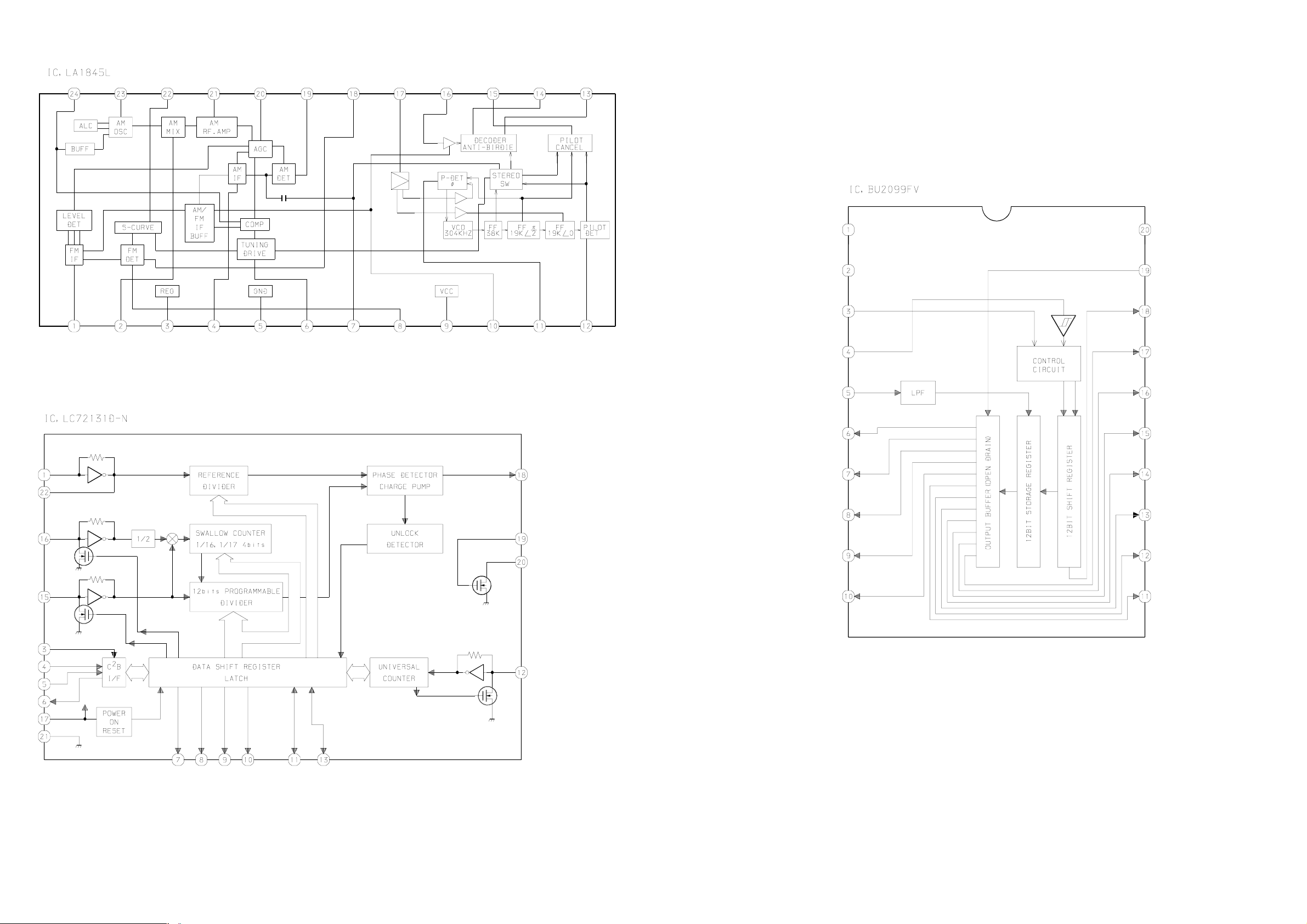
IC, LC876596W-5T96
Pin No. Pin Name I/O Description
1 CLK O Common serial clock output.
2 DATA O Common serial data output.
3 STB O Common serial strobe output.
4 CS-RHYTHM O Rhythm IC chip select output.
5 I-RDSDATA I RDS input data (Connected to ground).
6 HP-MUTE I Headphone plug-in detect input (output "L" at HOLD).
7 O-POWER O System power ON / OFF output.
8 PLL-CE O Tuner PLL IC chip enable output.
9 O-MUTE O System mute ON / OFF output.
10 CLK-SHIFT O MICON clock shift output (active low).
11 RESET - System reset.
12 VOL-JOG I Main volume rotary encoder input (AD).
13 MULTI-JOG I Dial jog rotary encoder input (AD).
14 VSS1 - Connected to ground.
15 CF 1 I Oscillator circuit input (9.43MHz).
16 CF 2 O Oscillator circuit output (9.43MHz).
17 VDD1 - Connected to power supply.
18 HOLD I Power supply voltage detect AD input.
19 KEY1 I Key input 1 (AD) (output "L" at HOLD).
20 KEY2 I Key input 2 (AD) (output "L" at HOLD).
21 KEY3 I Key input 3 (AD) (output "L" at HOLD).
22 I-SPEANNA I Spectrum analyzer IC AD input (output "L" at HOLD).
23 I-CDSW I CD mecha switches AD input (output "L" at HOLD).
24 I-DISH I CD turnable sensor input (output "L" at HOLD).
25 I-MIC I MIC input for auto vocal fader (output "L" at HOLD).
26 I-RDSCLK / I-WRQ I Turner RDS clock input (Not used) / CD sensor (output "L" at HOLD & INI).
27 I-TU-SIG / MS I Turner signal (Not used) / music sensor input (output "L" at HOLD).
28 I-TMBASE I Time base clock (8Hz) input (output "L" at HOLD).
29 I-RMC I Remote receiver data input (output "L" at HOLD).
30~42 G13~G1 O FL grid G13~G1 output.
43~45 P39~P37 O FL segment P39~P37 output.
46 VDD3 - Connected to power supply.
47 SPEANA A / P36 O Spectrum analyzer band control A / FL P36 segment output.
48 SPEANA B / P35 O Spectrum analyzer band control B / FL P35 segment output.
49 SPEANA C / P34 O Spectrum analyzer band control C / FL P34 segment output.
50 P33 O FL P33 segment output.
51 VP - Power for FL display.
52~59 P32~P25 O FL P32~P25 segment output.
60 NO AC-DEMO / P24 I/O No AC-DEMO input (Not used) / FL P24 segment output.
61 CASINO-DEMO / P23 I/O Casino DEMO input / FL P23 segment output.
62 ECO-ON / P22 I/O ECO ON (default setting) detect input / FL P22 segment output.
– 32 –
Page 3

Pin No. Pin Name I/O Description
63 NO-RHYTHM / P21 I/O No rhythm (beat master) function rhythm input (Not used) / FL P21 segment output.
64 AC3-DPL / P20 I/O AC 3 input + DOLBY PRO LOGIC detect input (Not used) / FL P20 segment output.
65 K-CON / P19 I/O K-CON diode detect input (Not used) / FL P19 segment output.
66 RDS / P18 I/O RDS function diode detect input (Not used) / FL P18 segment output.
67 FM1 / P17 I/O OIRT diode detect input (Not used) / FL P17 segment output.
68 SW / P16 I/O SW band diode detect input (Not used) / FL P16 segment output.
69 LW / P15 I/O LW band diode detect input (Not used) / FL P15 segment output.
70 AM-10K / P14 I/O AM-10K diode detect input / FL P14 segment output.
71 AM-ST / P13 I/O AM stereo diode detect input (Not used) / FL P13 segment output.
72 VDD4 - Connected to power supply.
73 REA / P12 I/O Deck 2 side A recordable switch input / FL P12 segment output.
74 CST1 / P11 I/O Deck 1 cassette detect input / FL P11 segment output.
75 CAM1 / P10 I/O Deck 1 CAM switch input / FL P10 segment output.
76 AUTO2 / P9 I/O Deck 2 auto stop input / FL P9 segment output.
77 AUTO1 / P8 I/O Deck 1 auto stop input / FL P8 segment output.
78 CAM2 / P7 I/O Deck 2 CAM switch input / FL P7 segment output.
79 REB / P6 I/O Deck 2 side B recordable switch input / FL P6 segment output.
80 CST2 / P5 I/O Deck 2 cassette detect input / FL P5 segment output.
81~84 P4~P1 O FL P4~P1 segment output.
85 K-SCAN O Key-scan output (active low).
86 SOL1 O Deck 1 solenoid output (active low).
87 SOL2 O Deck 2 solenoid output (active low).
88 O-MOTOR O Deck motor ON/OFF output.
89 VSS2 - Connected to ground.
90 VDD2 - Connected to power supply.
91 IFC-TU I Tuner tune-IF count input (active L).
92 I-STEREO I Tuner stereo detect input (active L).
93 I-SQDATA I CD SUBQ data input.
94 I-DRF I CD DRF input.
95 O-DISHREV O CD dish reverse output.
96 O-DISHFWD O CD dish forward output.
97 O-DATA (CD) O CD control data output.
98 CD-CE O CD control data latch output.
99 O-CLK (CD) O CD control clock output.
100 STB (SHIFT) O Shift register (BU2099) strobe output.
– 33 –
Page 4

ADJUSTMENT 1 <DECK>
< DECK SECTION >
1. Tape Speed Adjustment (DECK 2)
Settings : • Test tape : TTA–100 (3kHz)
• Test point : TP8 (Lch), TP9 (Rch)
• Adjustment location : SFR1
Method : Play back the test tape and adjust SFR1 so that the
frequency counter reads 3000Hz ± 5Hz (FWD) and
± 45Hz (REV) with respect to forward speed.
2. Head Azimuth Adjustment (DECK 1, DECK 2)
Settings : • Test tape : TTA–330 (315/10kHz)
• Test point : TP8 (Lch), TP9 (Rch)
• Adjustment location : Head azimuth
adjustment screw
Method : Play back (FWD) the 10kHz signal of the test tape
and adjust screw so that the output becomes maximum.
Next, perform on REV PLAY mode.
3. PB Frequency Response Check (DECK 1, DECK 2)
Settings : • Test tape : TTA–330 (315/10kHz)
• Test point :TP8 (Lch), TP9 (Rch)
Method : Play back the 315Hz and 10kHz signals of the test
tape and check that the output ratio of the 10kHz
signal with respect to that of the 315Hz signal is
0dB ± 2dB.
4. PB Sensitivity Adjustment (DECK 1, DECK 2)
Settings : • Test tape : TTA–200 (400Hz)
• Test point : TP8 (Lch), TP9 (Rch)
• Adjustment location : SFR301 (DECK 1, Lch)
SFR302 (DECK 1, Rch)
SFR303 (DECK 2, Lch)
SFR304 (DECK 2, Rch)
Method : Play back the test tape and adjust SFRs so that the
output level of the test points becomes
245mV ± 10mV.
6. REC/PB Sensitivity Check (DECK 2)
Settings : • Test tape : TTA–615 (CrO2)
• Test point : TP8 (Lch), TP9 (Rch)
• Input signal : 1kHz (0VU)
Method : Apply a 1kHz signal and REC mode. Then adjust
OSC attenuator so that the output level at the TP1
becomes 180mV. Record and play back the 1kHz signal
and check that the output is 0dB ± 1.5dB.
7. REC/PB Frequency Response Adjustment (DECK 2)
Settings : • Test tape : TTA–602 (Normal)
• Test point : TP8 (Lch), TP9 (Rch)
• Input signal : 1kHz / 10kHz (–20VU)
• Adjustment location :SFR351 (Lch)
SFR352 (Rch)
Method : Apply a 1kHz signal and REC mode. Then adjust OSC
attenuator so that the output level at the TP1
becomes 18mV. Record and play back the 1kHz and
10kHz signals and adjust SFRs so that the
output of the 10kHz signals becomes 0dB ± 0.5dB
with respect to that of the 1kHz signal.
8. REC/PB Frequency Response Check (DECK 2)
Settings : • Test tape : TTA–615 (CrO
• Test point : TP8 (Lch), TP9 (Rch)
• Input signal : 1kHz/10kHz(-20VU)
Method : Apply a 1kHz signal and REC mode. Then adjust
OSC attenuator so that the output level at the test point
becomes 18mV. Record and play back the 1kHz and
10kHz signals and check that the output is 0dB ± 2dB.
)
2
5. REC/PB Sensitivity Adjustment (DECK 2)
Settings : • Test tape : TTA–602 (Normal)
• Test point : TP8 (Lch), TP9 (Rch)
• Input signal : 1kHz (0VU)
• Adjustment location : SFR305 (Lch)
SFR306 (Rch)
Method : Apply a 1kHz signal and REC mode. Then adjust OSC
attenuator so that the output level at the test points
becomes 180mV. Record and play back the 1kHz and
and adjust SFRs so that the output level becomes
0dB ± 0.5dB.
– 34 –
Page 5

ADJUSTMENT 2 <TUNER / FRONT>
< TUNER SECTION >
1. Clock Frequency Check
Settings : • Test point : TP6 (CLK)
Method : Set to AM 1710kHz and check that the test point is
2160kHz ± 45Hz.
2. AM VT Check
Settings : • Test point : TP3 (VT)
Method : Set to AM 1710kHz and check that the test point is less
than 8.5V. Then set to AM 530kHz and check that the
test point is more than 0.6V.
3. AM Tracking Adjustment
Settings : • Test point : TP6 (Lch), TP7 (Rch)
• Adjustment location : L951(1/3)
Method : Set to AM 1000kHz and adjust L951(1/3) so that the
test point becomes maximum.
7. DC Balance / Mono Distortion Adjustment
Settings : • Test point : TP4, TP5 (DC balance)
TP8 (Lch), TP9 (Rch)
(Mono distortion)
• Adjustment location :L801
• Input level : 60dBµV
Method : Set to FM 98.0MHz and adjust L801 so that the
voltage between TP4 and TP5 becomes 0V ± 500mV
with distortion less than 0.5%.
8. Output Level Check
<AM>
Settings : • Test point : TP6 (Lch), TP7 (Rch)
• Input level : 74dBµV
Method : Set to AM 1000kHz and check that the test point is
50mV ± 3dB.
4. FM VT Adjustment
Settings : • Test point : TP3 (VT)
• Adjustment location : L906
Method : Set to FM 108.0MHz and adjust L906 so that the test
point becomes 7.0V ± 0.1V. Then set to FM 87.5MHz
and check that the test point is more than 0.5V.
5. FM Tracking Adjustment
Settings : • Test point : TP6 (Lch), TP7 (Rch)
• Adjustment location : L903
Method : Set to FM 87.5MHz and adjust L903 so that the test
point becomes maximum.
6. AM IF Adjustment
Settings : • Test point : TP6 (Lch), TP7 (Rch)
• Adjustment location :
L802 .................................................... 450kHz
<FM>
Settings : • Test point : TP6 (Lch), TP7 (Rch)
• Input level : 60dBµV
Method : Set to FM 98.0MHz and check that the test point is
150mV ± 3dB.
< FRONT SECTION >
1. µ-CON OSC Adjustment
Settings : • Test point : TP1 (K-SCAN)
TP2 (GND)
• Adjustment location : L191
Method : Insert AC plug while pressing of "POWER" key and
"TUNER" function key. Connect a frequency across
TP1 and TP2. Then adjust L191 so that the frequency
across the test point is 208.8Hz ± 0.2Hz.
– 35 –
Page 6

CD TEST MODE
1. How to Activate CD Test Mode
While pressing and holding the function button, insert the AC plug.
When the test mode starts, the message, “ TEST” appears on the display.
2. How to Cancel CD Test Mode
Press the POWER button or remove the AC plug.
* The test mode is cancelled by other function keys during play.
3. Function and Usage of CD Test Mode
No Mode Button for Display Operation Contents
Activation
1 Start Mode All lights are All FL are lit. • FL check
lit. • Microcomputer check
2 Search Mode STOP button Reading • Laser diode is lit during the • APC circuit check
mode. • Laser current measurement
• Focus search continuous • Focus-search waveform check
operation. *1 • Focus-error waveform check
• Spindle motor continuous kick. (DRF is ignored during search
mode)
3 Play Mode PLAY button Normal • Normal playback. • All servo circuits check
• Focus search continues if • DRF check
TOC READ cannot be read.
4 Traverse PAUSE Normal • Tracking Servo OFF/ON. • Tracking balance check
Mode button The OFF/ON operation repeats
each time the PAUSE button is
pressed.
5 Sled Mode FF button TEST • PU moves to inner track. *2
At the same time, the lens is • Sled circuit check
kicked to inner track. • Tracking circuit check
RWD button TEST • PU is moves to outer track. *2 • Mechanism operation check
At the same time, the lens is • PU check
kicked to outer track.
6 Spindle Mode REC/REC All lights are • When the button is pressed, • Spindle circuit check
MUTE button lit. the spindle motor operates in • Spindle motor check
forward rotation (rough speed).
Then, the button is pressed
again, it operates in reverse
rotation.
When the button is pressed
again, operation stops.
*1 … When focus search operates continuously more than 10 minutes, the protection circuit may start due to generation of heat in the
driver IC. If this happens, turn off the power, leave the unit for a while, and then, restart.
*2 … Carefully monitor the gear against damage, as the sled motor rotates while the FF or RWD button is pressed even when the
pickup is located at innermost or outermost.
– 36 –
Page 7

MECHANICAL EXPLODED VIEW 1 / 1
– 37 –
Page 8

MECHANICAL PARTS LIST 1 / 1
PART NO. DESCRIPTIONREF. NO. KANRI
NO.
1 8B-NF4-045-010 PANEL,TRAY
2 8B-NF4-041-010 COVER, TRAY
3 81-532-080-010 LBL,CASS-COMPT
4 82-NF5-229-010 PLATE,LOCK
5 86-NF9-224-010 SPR-C,LOCK
6 87-NF4-216-010 HLDR,LOCK 1
7 87-064-108-110 HLDR,NC LUTCH
8 82-NF5-218-010 SPR-T,EJECT 1 (SIN)
9 87-NF8-220-010 DMPR,150
10 8B-NF4-043-010 PANEL,COVER
11 8B-NF4-031-010 PANEL,UNDERCOVER
12 8B-NF4-001-010 CABI,FR
13 8B-NF4-083-010 REFLECTOR,FUNC
14 8B-NF4-212-010 HLDR,CHAS L-1
15 8B-NF4-213-010 HLDR,CHAS,L-2
16 8B-NF4-081-010 KNOB,RTRY JOG
17 8B-NF4-086-010 REFLECTOR,JOG
18 8B-NF4-077-010 RING,JOG H
19 8B-NF4-079-010 RING,VOL
20 8B-NF4-051-010 WINDOW,DISP
21 8B-NF4-044-010 PANEL,KEY-CD
22 8B-NF4-042-010 PANEL,CD
23 8B-NF4-070-010 KEY,ASSY CD
24 8B-NF4-201-010 GUIDE,LED CD
25 8A-NF8-206-010 HLDR,PWB M
26 87-A91-736-010 FAN,DSB0812M-S382 -300MM
27 8B-NF4-225-010 HLDR,FAN
28 8B-NF4-214-010 HLDR,CHAS R-1
29 8B-NF4-215-010 HLDR,CHAS R-2
30 8B-NF4-067-010 KEY,ASSY OPE
31 87-064-185-010 HLDR,WIRE
32 8B-NF4-064-010 KEY,BBE
33 8B-NF4-071-010 KEY,SPICE
34 8B-NF4-065-010 KEY,JOG
35 8B-NF4-062-010 KEY,ASSY FUNC
36 8B-NF4-202-010 GUIDE,FL
37 8B-NF4-061-010 KEY,GEQ
38 8B-NF4-069-010 KEY,REC
39 8B-NF4-066-010 KEY,KARAOKE
40 8B-NF4-084-010 REFLECTOR,OPE
DESCRIPTIONREF. NO. KANRI
PART NO.
41 87-NF4-217-110 HLDR,LOCK 2
42 82-NF5-219-010 SPR-T,EJECT 2 (SIN)
43 8A-NF3-213-110 HLDR,HT-SINK L
44 8A-NF3-214-110 HLDR,HT-SINK R
45 8A-NF3-212-110 HLDR,REAR
46 87-A80-157-010 AC CORD ASSY,E BLK CC
!
47 8B-NF4-633-010 FAN,AD0612DS-D70GL
48 87-A91-870-010 F-BEAD,9.5-17.5-28.5 TAITECH
49 87-085-185-010 BUSHING, AC CORD (E)
50 84-ZG1-245-210 CAP,OPTICAL
51 8A-NF3-027-110 CABI,STEEL
52 8A-NF3-026-110 CABI,BOTTOM
53 8B-NF4-021-010 BOX,CASS L
54 8B-NF4-058-010 WINDOW,CASS L
55 8Z-NF3-048-010 COVER, BOTTOM
56 8B-NF4-059-010 WINDOW,CASS R
57 8B-NF4-022-010 BOX,CASS R
58 8B-NF4-020-010 COVER, FAN
59 8A-MA3-214-010 W,3.5-6.5-1 W/ADH
60 8A-NHP-214-010 HLDR,HL
61 8B-NF4-011-010 CABI,REAR LHSM
A 87-067-703-010 TAPPING SCREW, BVT2+3-10
B 87-067-581-010 TAPPING SCREW, BVT2+3-15
C 87-NF4-224-010 S-SCREW,IT3B+3-8 CU
D 87-721-097-410 QT2+3-12 GLD
E 87-591-095-410 TAPPING SCREW, QIT+3-8 (GLD)
F 87-067-689-010 TAPPING SCREW, BVTT+3-8
G 87-067-975-010 S-SCREW,IT+4-8
H 87-B10-190-010 BVT2+3-22 W/O SLOT
I 87-067-761-010 TAPPING SCREW, BVT2+3-10
J 87-721-096-410 QT2+3-10 GLD
K 87-067-758-010 BVT2+3-12 W/O SLOT
L 87-067-660-010 BVT2+3-8 W/O SLOT BLK
M 87-067-641-010 UTT2+3-8(W/O SLOT)BL
NO.
COLOR NAME TABLE
Basic color symbol Color Basic color symbol Color Basic color symbol Color
B Black C Cream D Orange
G Green H Gray L Blue
LT Transparent Blue N Gold P Pink
R Red S Silver ST Titan Silver
T Brown V Violet W White
WT Transparent White Y Yellow YT Transparent Yellow
LM Metallic Blue LL Light Blue GT Transparent Green
LD Dark Blue DT Transparent Orange GM Metallic Green
YM Metallic Yellow DM Metallic Orange PT Transparent Pink
LA Aqua Blue GL Light Green HT Transparent Gray
– 38 –
Page 9

TAPE MECHANISM EXPLODED VIEW 1 / 1
50
A
48
51
49
47
44
B
C
46
52
53
a
54
A
9
B
47
48
49
50
29
60
31
38
35
29
58
a
37
32
29
30
39
51
43
40
43
37
39
35
36
7
27
38
32
31
58
b
PWB
8
1
2
3
PLATE
SHLD,M3
4
5
6
60
29
30
E
44
C
45
46
52
53
b
54
55
40
25
12
13
14
11
15
16
33
59
10
56
33
25
18
D
20
17
19
24
11
GEAR,
PLAY
21
57
23
PWB
7
8
28
19
42
26
13
15
14
16
17
18
20
4
GEAR,
PLAY
PLATE
SHLD,M3
D
5
6
21
19
28
23
41
24
42
YPR7NM,PR7NM
22
22
PWB
55
34
– 39 –
Page 10

TAPE MECHANISM PARTS LIST 1 / 1
PART NO. DESCRIPTIONREF. NO. KANRI
NO.
1 82-ZM3-335-310 PULLEY,COUPLER M3
2 87-B10-043-010 W-P,0.99-4-0.25 SLT
3 86-ZM1-206-010 BELT,MAIN L
4 82-ZM1-322-010 SPR-T,FR 60
5 82-ZM1-220-210 GEAR,IDLER
6 82-ZM3-616-010 RING MAGNET 4
7 82-ZM3-348-010 LEVER ASSY,PINCH YL
8 82-ZM1-258-210 SPR-T,PINCH L
9 87-A91-195-110 HEAD,RPH KC9142 FPC
10 82-ZM3-342-010 BELT,SBU MOT 3
11 82-ZM1-338-110 BELT,FR 4
12 09-001-420-010 FLY-WHL,R ASSY
13 82-ZM3-333-310 SLIP DISK ASSY 2
14 82-ZM3-334-010 PW 2.16-6-0.4
15 82-ZM3-306-110 LVR,FR M2
16 82-ZM1-225-210 GEAR,FR
17 82-ZM3-305-310 GEAR,CAM M2(*)
18 82-ZM1-226-010 GEAR,REW
19 82-ZM1-216-510 GEAR,REEL
20 82-ZM1-227-310 LVR,TRIG
21 82-ZM1-265-310 SPR-E,TRIG
22 82-ZM3-351-010 HLDR,IC 2
23 82-ZM3-343-010 LEVER ASSY,PINCH YR
24 82-ZM1-259-210 SPR-T,PINCH R
25 82-ZM1-234-310 FLY-WHL,L ASSY
26 82-ZM1-237-610 FLY-WHL,R ASSY
27 82-ZM3-339-110 SHAFT,COUPLER N3
28 82-ZM1-255-310 SPR-E,LVR DIR
29 82-ZM1-217-410 REEL TABLE
30 82-ZM1-285-410 SPR-C,BT L
31 82-ZM1-333-210 PLATE,LINK2
32 82-ZM1-222-310 LVR,PLAY(*)
33 82-ZM3-307-010 CUSH-G,DIA3.7-8-3.2
34 87-045-347-010 MOT,SHU2L 70
35 82-ZM1-257-010 SPR-T,CAS
DESCRIPTIONREF. NO. KANRI
PART NO.
NO.
36 82-ZM3-340-010 SH,BELT D2
37 82-ZM1-242-010 LVR,CAS
38 82-ZM1-244-510 SPR-C,BT
39 82-ZM1-243-010 LVR,STOP
40 82-ZM1-240-110 LVR,REC(*)
41 82-ZM1-264-010 LVR,EJECT R
42 82-ZM3-621-110 SOL ASSY 27 KO
43 82-ZM1-241-310 LVR,MC
44 82-ZM1-208-310 HLDR,HEAD
45 87-A91-196-110 HEAD,PH KP9142 FPC
46 82-ZM1-314-110 PLATE,HEAD
47 82-ZM1-207-910 GUIDE,TAPE
48 82-ZM3-353-010 SPR-T,HEAD 2
49 82-ZM1-210-110 GEAR,H T
50 82-ZM1-219-110 SPR-T,LINK
51 82-ZM1-269-210 SPR-T,BRG
52 82-ZM1-218-010 SPR-E,HB
53 82-ZM1-206-910 CHAS,HEAD
54 82-ZM1-266-310 LVR,DIR
55 82-ZM1-214-010 SPR-T,DIR
56 82-ZM3-221-210 PULLEY,MOT 2M
57 82-ZM3-301-610 CHAS ASSY,M2
58 80-ZM6-243-010 SH 1.75-3.6-0.5 SLT
59 82-ZM3-329-410 BELT,SBU R2
60 82-ZM1-288-010 SH,1.63-3.2-0.5 SLT
A 80-ZM6-207-010 V+1.6-7
B 86-ZM4-206-110 S-SCREW,AZIMUTH L
C 85-ZM3-202-010 S-SCREW,TG
D 82-ZM3-222-010 S-SCREW,SHILD PLATE
E 82-ZM3-318-110 S-SCREW W,MOTOR M2
– 40 –
Page 11

GENERAL SPEAKER DISASSEMBLY INSTRUCTIONS (FOR REFERENCE)
Type.1
Insert a flat-bladed screwdriver into the position indicated by the
arrows and remove the panel. Remove the screws of each speaker
unit and then remove the speaker units.
Type.2
Remove the grill frame and four pieces of rubber caps by pulling
out with a flat-bladed screwdriver. Remove the screws from hole
where installed rubber caps. Insert a flat-bladed screwdriver into
the position indicated by the arrows and remove the panel. Remove the screws of each speaker unit and then remove the speaker
units.
Type.4
TOOLS
1 Plastic head hammer
2 (() flat head screwdriver
3 Cut chisel
12 3
How to Remove the PANEL, FR
1. Insert the (() flat head screwdriver tip into the gap
between the PANEL, FR and the PANEL, SPKR. Tap the
head of the (() flat head screwdriver with the plastic
hammer head, and create the clearance as shown in Fig-1.
2. Insert the cut chisel in the clearance, and tap the head of
the cut chisel with plastic hammer as shown in Fig-2, to
remove the PANEL, FR.
Type.3
Insert a flat-bladed screwdriver into the position indicated by the
arrows and remove the panel. Turn the speaker unit to counterclockwise direction while inserting a flat-bladed screwdriver into
one of the hollows around speaker unit, and then remove the speaker
unit. After replacing the speaker unit, install it turning to clockwise
direction until "click" sound comes out.
3. Place the speaker horizontally. Tap head of the cut chisel
with plastic hammer as shown in Fig-3, and remove the
PANEL, FR completely.
Fig-1 Fig-2
How to Attach the PANEL, FR
Attach the PANEL, FR to the PANEL, SPKR. Tap the four
corners of the PANEL, FR with the plastic hammer to fit the
PANEL, FR into the PANEL, SPKR completely.
– 41 –
Fig-3
Page 12

SPEAKER PARTS LIST
(SX-WNT929) <YLSL>
PART NO.
NO.
1 8B-MS3-001-010 PANEL,FR
2 8B-MS3-004-010 PANEL,TW A
3 8B-MS3-005-010 PANEL,TW B
4 8B-MS3-006-010 PANEL,DUCT A
5 8B-MS3-007-010 PANEL,DUCT B
6 8B-MS3-008-010 PANEL,DUCT C
7 8B-MS3-009-010 PROTECTOR,SQ
8 8B-NS5-610-010 CORD,SPKR
9 8B-NS3-606-010 SPKR,W 160/35
10 8B-NS3-608-010 SPKR,W 140/25
11 8B-NSK-604-010 SPKR,T 60
DESCRIPTIONREF. NO. KANRI
ACCESSORIES / PACKAGE LIST
PART NO.
1 8B-NF4-902-010 IB,LH (ESP) M
2 87-006-268-010 ANT,LOOP AM
3 8Z-NF5-702-010 RC UNIT,ZAS04
4 87-043-115-010 FEEDER-ANT,FM
!
5 87-A91-017-010 PLUG,CONVERSION JT-0476
NO.
DESCRIPTIONREF. NO. KANRI
– 42 –
Page 13

2–11, IKENOHATA 1–CHOME, TAITO-KU, TOKYO 110, JAPAN TEL:03 (3827) 3111
Printed in Singapore2000068 9630472 0251431
 Loading...