

Page 1

CIELO/NEXIA(LHD)
OWNER'S MANUAL
Page 2

FOREWORD
This manual has been prepared to acquaint you with the operation and maintenance
of your new DAEWOO and to provide important safety information. We urge you to
read it carefully and follow the recommendations to help assure the most enjoyable,
safe and trouble-free operation of your vehicle.
When it comes to service, remember that your DAEWOO dealer knows your vehicle
best and is interested in your complete satisfaction.
We would like to take this opportunity to thank you for choosing a DAEWOO product
and assure you of our continuing interest in your motoring pleasure and satisfaction.
This manual should be considered as a permanent part of your vehicle, and must remain
with the vehicle at the time of resale.
DAEWOO MOTOR CO., LTD.
INCHON, KOREA
Page 3

IMPORTANT NOTICE
Please read this manual and follow its
instructions carefully.
To emphasize special information, the words
WARNING, CAUTION, and NOTE have
special meanings.
Information following these signal words
should be carefully reviewed.
WARNING
The instructions must be observed in
order to reduce the risk of personal
injury. Please read these warnings; if
you don't, then you or others could be
hurt.
CAUTION
These instructions point out special
service procedures or precautions that
must be followed to avoid damaging the
vehicle.
Your Daewoo car or other property can
be damaged if you don't follow these
instructions.
NOTE
Notes provide special information which
makes maintenance easier or important
instruction clearer.
All informations, illustrations and
specifications in this manual are based on
the latest product informations available at
the time of publication.
Daewoo reserves the right to change
specifications or design at any time without
notice and without incurring any obligation
whatsoever.
This vehicle may not comply with the
standards or regulations of other countries.
Before attempting to register this vehicle in
any other country, check all applicable
regulations and make any necessary
modifications.
This manual describes options and trim
levels available at the time of printing, and
therefore, some of the items covered may
not apply to your vehicle. If any doubt exists
about any of the options or trim levels,
please do not hesitate to contact your
Daewoo dealer for information on the latest
specifications.
* This asterisk in this manual signifies
that an item of equipemt is not included
in all vehicles (model variants, engine
options, models specific to one country,
optional equipment, etc.)
We would like to point out that non-Daewoo
Genuine parts and accessories have not
been examined and approved by Daewoo,
and in spite of continuous market product
monitoring, we cannot certify the suitability
nor the safety of such products whether
they are installed or intended for fitment in
our vehicles. Daewoo is not liable for any
damage caused by the use of non-Daewoo
Genuine parts and accessories.
Page 4

TABLE OF CONTENTS
1. BEFORE DRIVING YOUR CAR ........................................................................................................................... 1ñ1
2. STARTING AND OPERATING.............................................................................................................................. 2ñ1
3. INSTRUMENT AND CONTROLS ......................................................................................................................... 3ñ1
4. OTHER CONTROLS AND FEATURES ................................................................................................................ 4ñ1
5. VENTILATION, HEATING AND AIR CONDITIONING
6. AUDIO SYSTEM* ................................................................................................................................................. 6ñ1
7. IN CASE OF EMERGENCY ................................................................................................................................. 7ñ1
8. SERVICE AND MAINTENANCE .......................................................................................................................... 8ñ1
9. VEHICLE CARE .................................................................................................................................................... 9ñ1
10. SPECIFICATION AND SERVICE DATA ............................................................................................................. 10ñ1
* .......................................................................... 5ñ1
Page 5

BEFORE DRIVING YOUR CAR
1ñ1
Page 6
BEFORE ENTERING THE CAR
BEFORE DRIVING OFFBREAK-IN PERIOD
Following a few simple precautions for the
first few hundred kilometers can add to
the future performance, economy and long
life of your car.
ï Do not race the engine.
ï Drive at varying speeds, trying not to
"strain" the engine.
ï Avoid hard stops, except in
emergencies.
This will allow the brakes to bed in
properly.
ï Ensure that windows, outside rearview
mirrors and lights are clean, undamaged
and unobstructed.
ï Visually note inflation condition of tires.
ï Check that all lights are working.
ï Check that the area is clear if you are
about to reverse.
ï Check under the vehicle for leaks.
ï Adjust your seating position.
ï Adjust inside and outside mirrors.
ï Ensure that all occupants of the car
have fastened their seat belts.
ï Check the operation of the warning
lights when key is turned to "II" position.
ï Check all gauges.
ï Release the parking brake and ensure
that the brake warning light goes out.
ï Be sure you understand your car and
its equipment and how to operate it
safely.
WARNING
It is the owner's responsibility to
frequently check all lights, signaling
systems and warning indicator lights. It
is important that any malfunction is
corrected promptly to ensure the safety
of you, your passenger and other
drivers.
ï Avoid full-throttle starts.
1ñ2
Page 7
KEY
DOOR LOCKS
Two keys are provided which fit all key
cylinders.
Keep one of the two keys as a spare.
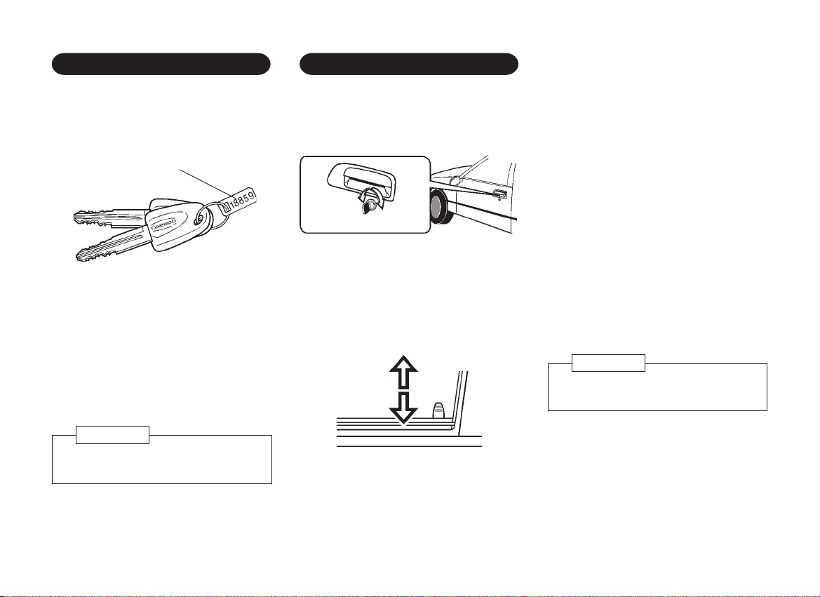
Key number plate
The key number is stamped on the key
number plate. For vehicle security, keep the
key number plate in a safe place, not in the
vehicle. You should also record the key
number in a safe place, not in the vehicle.
This deters unauthorized persons from
obtaining a duplicate key.
WARNING
Before leaving the vehicle, remove the
ignition key.
Front doors can be locked or unlocked from
outside by using the key.
unlocklock
To unlock, turn the key towards the rear of
the car. All doors can be locked or unlocked
from the inside by pushing down or pulling
up the door lock button located on the
window sill on each door.
unlock
lock
All doors, except the driver's, can be locked
from the outside by pushing down the door
lock button then closing the door.
The lock button on the driver's door cannot
be pushed down when the door is open,
thus preventing the driver from being
inadvertently locked out.
However, if the door handle is raised, the
lock button on the driver's door can be
pushed down when the door is open.
If you wish to lock the driver's door without
using the key, set the button in the lock
position before closing the door. The outside
door handle must be held up while the
driver's door is being closed.
CAUTION
Be careful not to lock your keys in the
vehicle.
1ñ3
Page 8
CENTRAL DOOR LOCKING
CHILD SAFETY DOOR LOCKS
ï To open the door from the inside,
1. Pull the door lock button up,
2. Pull the door catch.
pull
SYSTEM
By pressing down or pulling up the interior
lock button on the driver's door or by
turning the key as far as it will go, all doors
are locked or unlocked.
unlock
lock
*
NOTE
Always remove the ignition key and
lock all doors when leaving your
vehicle unattended.
When the metal latch beneath the lock on
either of the rear doors is pushed upwards,
the door cannot be opened from the inside.
Rear doors locked with the child safety
mechanism can still be opened from the
outside provided that the door lock button
is not pushed down.
upwards
latch
1ñ4
Page 9
REAR QUARTER WINDOWS
* POWER WINDOW SWITCHES*
DOOR WINDOWS*
To open, pull catch and push window
glass outwards to the open position.
When closing, fold catch back to lock.
To raise or lower the door window, rotate
the window regulator handle in the door
panel.
3 door model
The front windows can be operated by two
rocker switches on the center console
when the ignition switch is placed in
position "II".
Driver's
side switch
Passenger's
side switch
1ñ5
Page 10
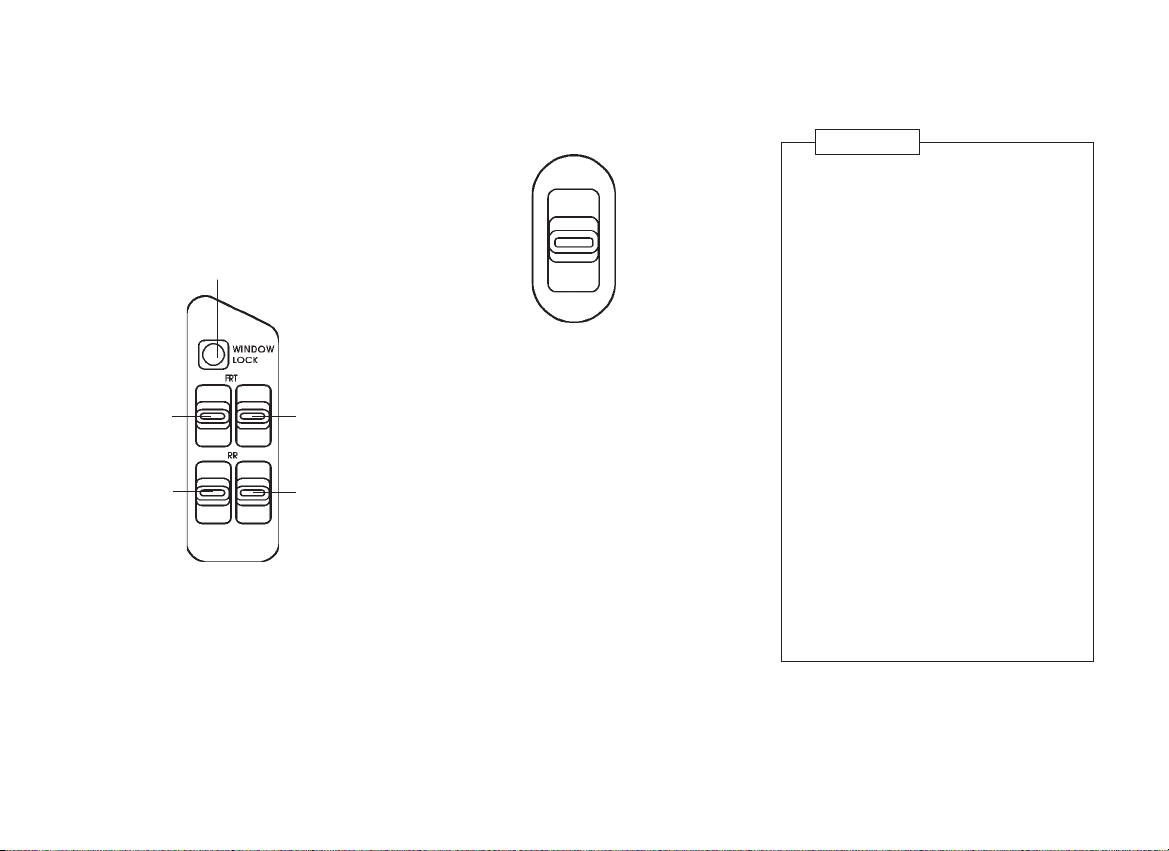
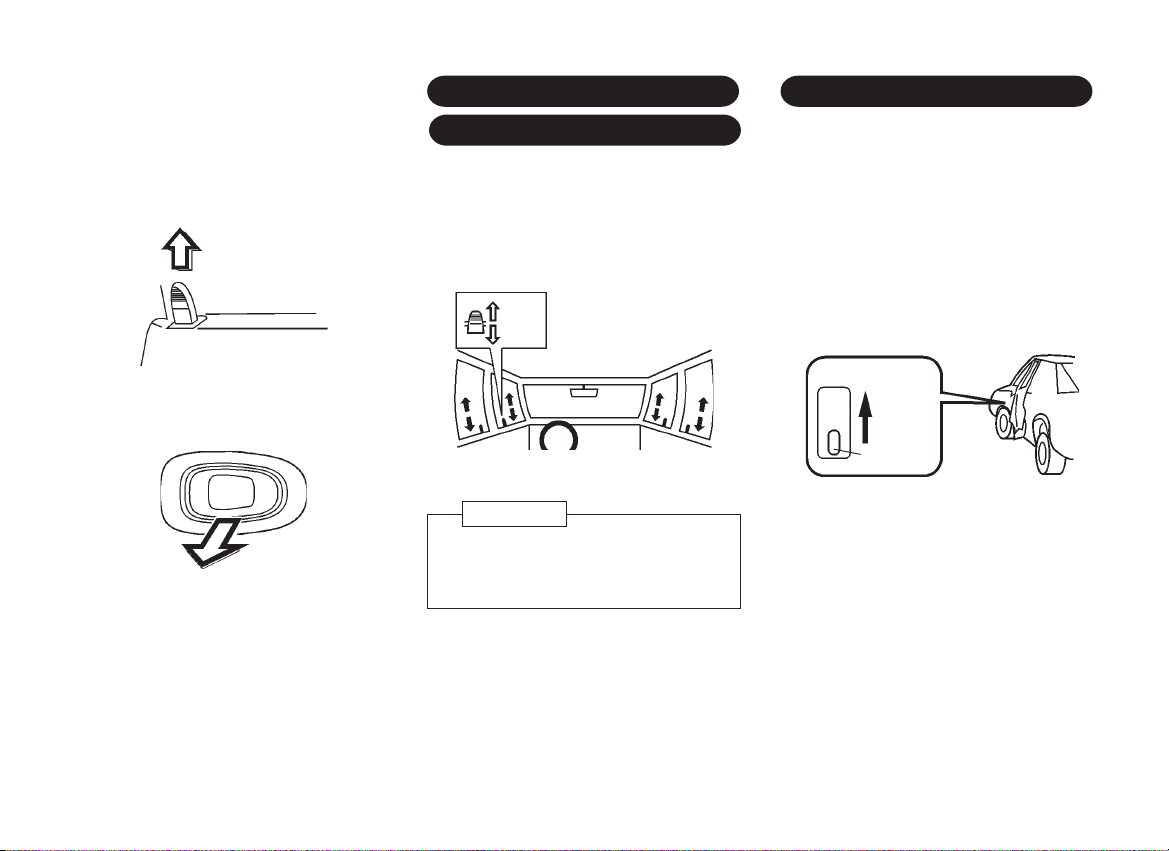
4 and 5 door models
The windows can be operated by switches
located in the driver's door armrest when
the ignition switch is in position "II".
Safety lock switch
Driver's side
switch
Rear left
side switch
When the safety lock switch is depressed,
power is cut to the individual door window
switches. However, the driver can still
operate all the windows using the switches
in the driver's door armrest.
Passenger's
side switch
Rear right
side switch
Passenger's door window switches are
located in the armrest of each door. Push
the switch down to lower the window and
push the switch up to raise the window.
Release the switch when the window
reaches the desired position.
When the safety lock switch is pressed, the
passenger's windows cannot be operated
except by the driver.
WARNING
Care must be taken when operating the
power windows. There is a risk of injury,
particularly for children, and a danger
that articles could become trapped.
Make sure that all vehicle occupants
know how to operate the windows
correctly.
If there are children on the rear seat,
press the safety lock button to isolate
the individual window switches.
Keep a close watch on the windows
when closing them. Ensure that nothing
becomes trapped in them.
Upon leaving the vehicle the driver
must remove the ignition key in order
to prevent other vehicle occupants from
operating the windows (with a potential
risk of injury).
Do not extend any portion of your body
out of the opening at any time.
1ñ6
Page 11
TILTABLE STEERING WHEEL
*
INSIDE REARVIEW MIRROR
The steering wheel can be adjusted in four
different positions.
pull
This steering wheel can be adjusted by
pulling with the left hand the control lever
on the side of the steering column, moving
the wheel to the desired position and then
releasing the lever. In order to provide easy
access to the vehicle, the wheel should be
moved to its uppermost position when
leaving the car.
CAUTION
Do not adjust the tiltable steering
wheel while the vehicle is moving to
avoid losing control of the vehicle.
The inside mirror can be adjusted up, down
or sideways to obtain the best view.
The inside mirror has day and night
positions.
Move the knob to the night position to
reduce glare from the headlights of vehicles
behind you.
adjusting knob
day
night
CAUTION
Always adjust the mirror with the
selector set to the day position.
Only use the night position if it is
necessary to reduce glare from the
headlights of vehicles behind you.
Be aware that in this position you may
not be able to see some objects that
could be seen in the day position.
WARNING
Do not put large objects on the flat area
behind the rear seat, as they may
obscure vision and could become
dangerous projectiles in the event of a
sudden stop or collisions.
1ñ7
Page 12
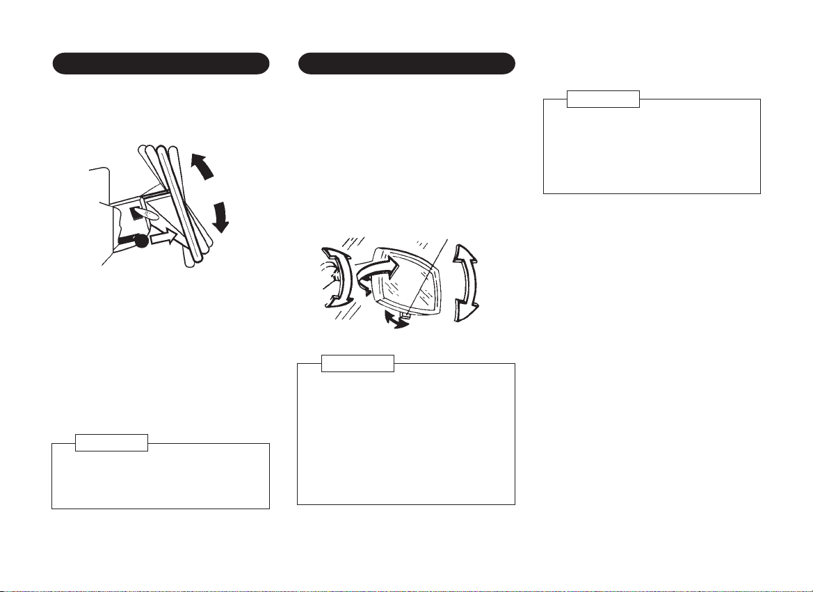
OUTSIDE REARVIEW MIRROR
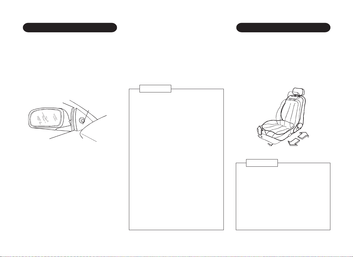
FRONT SEAT SLIDE ADJUSTMENT
Adjust the outside rearview mirrors with
the adjusting levers so that you can see
not only each side of the road behind you
but also each side of your vehicle. This
helps you determine the location of objects
seen in the mirror.
Simply move the adjusting lever in the
desired direction to adjust the position of the
mirror.
adjusting
lever
ï Foldable mirror*
The outside rearview mirrors can be folded
flat against the side of the vehicle by
pushing it backward when driving in narrow
road or washing the vehicle, etc.
ï Break-away mirror*
The outside mirrors will be released from
their supports under heavy impact for the
safety of passengers and pedestrians. The
mirrors can be locked back into position with
a light blow of the hand at light angles to
the vehicle.
ï Convex mirror*
The outside mirror on the passenger's side
is convex if it says "OBJECTS IN MIRROR
ARE CLOSER THAN THEY APPEAR".
Use this mirror to get a wider view of the
road behind.
CAUTION
ï Take care when judging the size or
distance of a vehicle or other object
seen in the side convex mirror. Be
aware that objects will look smaller
and appear farther away than when
viewed in a flat mirror.
ï Use your inside rearview mirror to
determine the size and distance of
objects seen in the side convex
mirror.
ï Do not scrape ice off the mirror
face; This may damage the surface
of the glass. If ice should restrict
movement of the mirror, do not
force the mirror adjust it.
ï To remove ice, use a deicer (spray
or blower, for example), sponge or
soft cloth.
ï Be sure to adjust mirror angles
before driving.
To move the seat forwards or backwards,
pull up the control lever located inboard and
under the front of the seat and hold it.
Then, slide the seat to the desired position
and release the lever.
pull
WARNING
Do not adjust the driver's seat while
the vehicle is moving to avoid losing
control of the vehicle.
After adjustment, rock the seat back
and forth to be sure it is securely
locked.
Make sure that the driver's seat is
properly adjusted before you start
driving.
1ñ8
Page 13
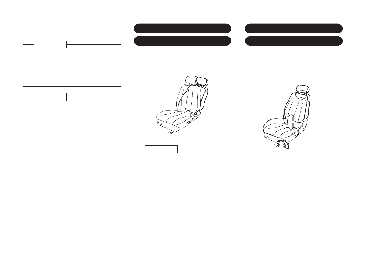
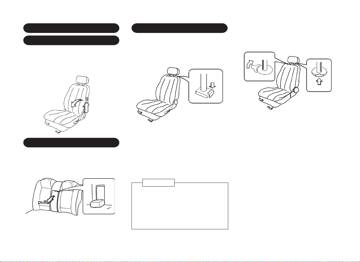
FRONT SEAT RECLINING
DRIVER'S SEAT HEIGHT
WARNING
To avoid excessive seat belt slack,
which reduces the effectiveness of
seat belts, make sure that the seats
are adjusted before the seat belts are
fastened.
CAUTION
Do not place articles under the front
seat that may interfere with the seat
lock mechanism. Loose objects might
interfere with seat-slide mechanism.
ADJUSTMENT
To adjust the seat back, lift up the lever (or
rotate the recliner) until the desired angle is
achieved.
lift up
WARNING
The seat backs should always be in a
fairly upright position when driving, or
the effectiveness of the seat belts may
be reduced.
The seat belts are designed to offer
maximum protection when seat backs
are in the fully upright position.
Make sure that the reclining seat backs
are properly adjusted before you start
driving.
ADJUSTMENT
The desired seat height can be achieved by
turning the crank handle located below the
driver's seat.
turn
*
1ñ9
Page 14
TILTING BACK OF FRONT
HEAD RESTRAINTS
SEATS
3 door vehicles only:
For access to the rear seat area, pull up
the release lever to fold the front seat
forward.
REAR SEAT ARMREST
4 door vehicles:
The pull-down rear seat armrest is located
in the center of rear seat.
Incorporated in the armrest is an opening
for the ski sleeve, for carrying long/thin
loads.
*
lift-up
*
Head restraints are designed to help reduce
the risk of neck injuries.
<sedan models>
press
To raise the head restraint, pull it up. To
lower it, press the lock release button on
the left side of head restraint at the seat and
push the head restraint down.
To remove the head restraint, pull it up as
far as it will go while pushing the lock
release.
CAUTION
Adjust the top of the head restraint so
that it is closest to the top of your ears.
After adjusting the head restraint,
make sure it is locked in position.
Do not drive with the head restraint
removed.
<hatchback models>
turn
rear
seat
To adjust the front seat head restraint, pull
it up or push it down.
To remove the head restraint, pull it up as
far as it will go while pushing the lock
release button on the left side of head
restraint at the seat.
To adjust or remove the head restraint
the rear seat, push the lock release lever
on the right side of head restraint rearward
and slide it up or down.
push
front
seat
* of
1ñ10
Page 15
SEAT BELT PRECAUTIONS
To protect you and your passengers in the
event of an accident, it is recommended that
the seat belts be worn by all occupants
whilst the vehicle is in use. Seat belts should
be worn correctly.
Rear passengers not wearing seat belts are
a danger to the driver and front passenger
in the event of an accident.
The seat belts are designed to be used by
only one person at a time: they are not
suitable for use by children below 6 years
of age. Suitable child seats/booster
cushions should be fitted.
WARNING
It is recommended that pregnant
women should wear a lap-shoulder
belt properly if at all possible. This will
reduce the likelihood of injury to both
the woman and the unborn child. The
lap belts should be worn as low as
possible throughout the pregnancy.
NOTE
If the belt locks when being pulled out,
rewind it completely in the retractor,
then pull it out to the desired length.
WARNING
ï To help reduce the risk of personal
injury in collisions or sudden
maneuvers, use the safety belts
following these instructions on their
proper use, maintenance, and use
with child restraint systems.
ï Children small enough for child
restraints (as indicated on the label
of such restraints) should always be
transported in them. Accident
statistics indicate children are safer
when properly restrained in the rear
seat rather than in the front seat.
Accordingly, a child restraint
system should be placed in the rear
seat.
ï Children who have outgrown child
restraint systems should sit in the
rear seat and be restrained with the
seat belt. If child's seating position
has a shoulder belt which is on or
very close to the face or neck,
move the child close to the center
of the vehicle, slightly inboard of the
shoulder belt, or move the child to
a position without a shoulder belt if
possible.
WARNING
ï Make sure that each seat belt
buckle is inserted into the proper
buckle catch. It is possible to cross
the buckle in the rear seat.
ï Do not wear your seat belt over
hard or breakable objects in your
pockets or on your clothing. If an
accident occurs, objects such as
glasses, pens, etc. under the seat
belt can cause injury.
ï Never wear the shoulder belt under
your arm nearest door. Make sure
that the shoulder portion of seat belt
is positioned midway over the
shoulderñnever across the neck.
ï Be sure the lap belt is fitted snugly
around the hips, not the waist.
ï Never use a belt for more than one
person at a time.
ï Never allow a child stand up or
kneel on the seat.
ï Never allow a child to be held in
somebody's arms while the vehicle
is moving.
ï Never let the belt system become
damaged by a door or seat.
1ñ11
Page 16
THREE POINT SEAT BELT
WARNING
ï Never wear the belts with straps
twisted or with a buckle release
button facing downward or inward.
ï Do not put anything into the opening
where the safety belt passes
through the trim panel. This may
jam the retractor or damage the
belt.
ï The seat belt will provide
maximum protection for its wearer
if the recliner seat back is placed
in fully upright position. When the
seat back is reclined, there is
greater risk that the passenger will
slide under the belt, especially in
a forward impact accident, and
may be injured by the belt or by
striking the instrument panel or
seat backs.
ï No modifications or additions
should be made by the user which
will either prevent the seat belt
adjusting devices from operating to
remove slack, or prevent the seat
belt assembly from being adjusted
to remove slack.
WARNING
ï Seat belts should be adjusted as
firmly as possible, consistent with
comfort, to provide the protection
for which they have been designed.
A slack belt will greatly reduce the
protection afforded to the wearer.
ï Care should be taken to avoid
contamination of the webbing with
polishes, oils and chemicals, and
particularly battery acid. Cleaning
may safely be carried out using
mild soap and water. The belt
should be replaced if webbing
becomes frayed, contaminated or
damaged.
ï Periodically inspect seat belt
assemblies for excessive wear and
damage. It is essential to replace
the entire seat belt assembly after
it has been worn in a severe
impact, even if damage to the
assembly is not obvious.
Each Daewoo vehicle is equipped with three
point seat belts with automatic retractors,
allowing freedom of body movement when
driving at even, constant speeds, although
the spring-tensioned belts are always a
snug fit.
This type of belt requires no length
adjustment. Once worn, the belt adjusts
itself to the movement of wearer, but in the
event of a sudden or strong shock, the belt
automatically locks to restrain the wearer's
body.
1ñ12
Page 17
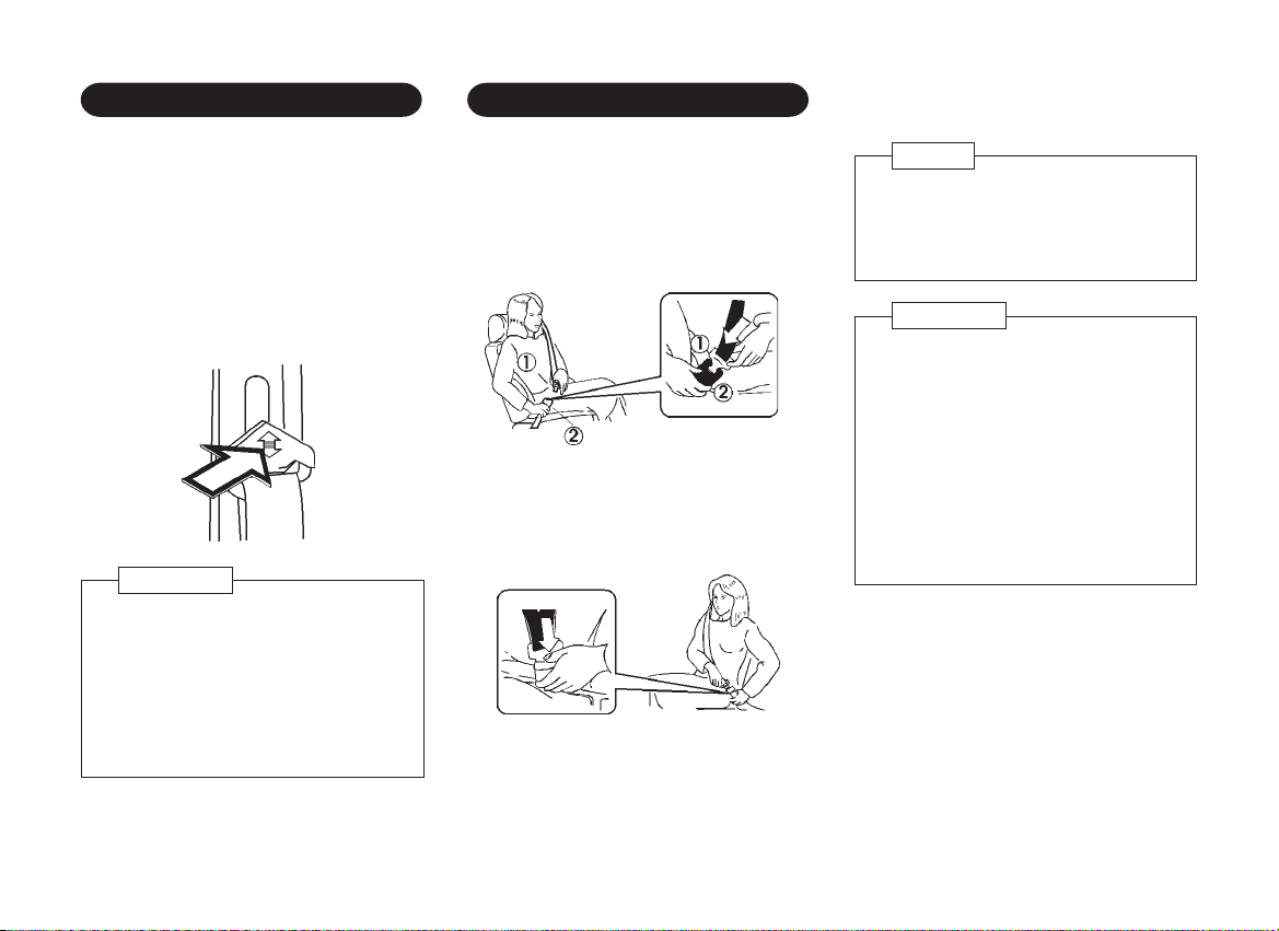
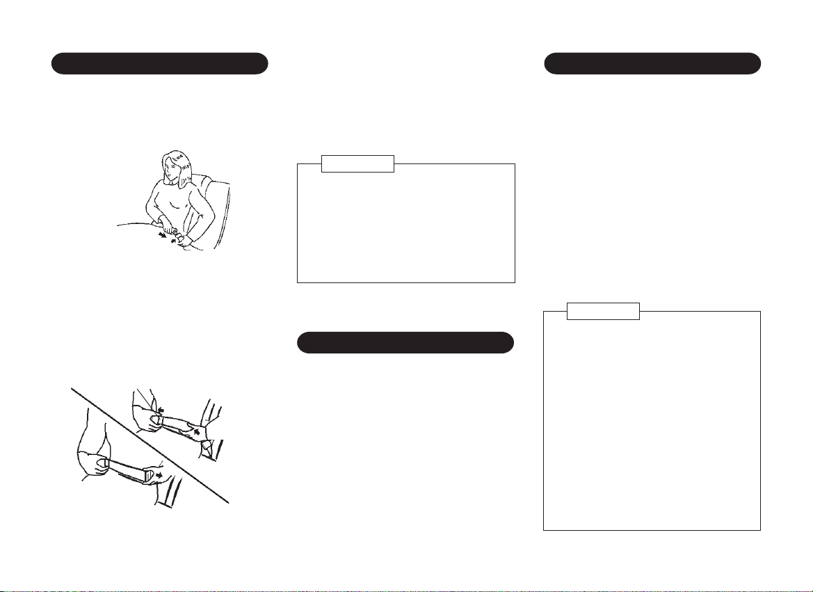
SEAT BELT HEIGHT ADJUSTOR
*
USING THE BELT
On seat belts with a height-adjustable upper
anchorage point: pull belt out, depress the
area indicated by an arrow and adjust the
height.
This is particularly important if a smaller
person has previously selected a lower
position.
Too high a position can impair comfort.
press
CAUTION
Always be sure that the belt is
positioned across the shoulder, as
close to your neck as possible and not
on your upper arm or neck. Failure to
do so could reduce the amount of
protection in an accident and increase
the chance of injury.
Pull the belt evenly out of the retractor and
guide it across the body, making certain that
it is not twisted.
Insert the metal latch plate
buckle
To remove the belt, depress the red pushbutton on the buckle. The belt will retract
automatically.
d
press
.
into the
c
NOTE
If the belt locks when being pulled out,
rewind it completely in the retractor,
then pull it out to the desired length.
WARNING
Both arms should not be under or over
the shoulder belt. Rather, one should
be over and the other under.
Do not wear the shoulder portion of
seat belt under the arm. Make sure
that the shoulder portion of seat belt
is positioned midway over the
shoulderñnever across the neck, and
the lap portion of the belt is fitted
snugly around the hips, not the waist.
1ñ13
Page 18
LAP BELT
CARE OF BELTS
A lap belt is installed in the center of the
rear seat.
Insert the tongue into the buckle until it
locks.
INSERT to fasten
PRESS to unfasten
To lengthen, hold the tongue at right angles
to the belt and pull on the belt. To shorten,
pull the free end of the belt away from the
tongue, then pull the belt clip to take up the
slack.
Belt clip
PULL
PULL
PULL to
lengthen
Position the lap belt low on the hips.
To remove the belt, depress the red button
on the buckle.
CAUTION
Never wear the lap belt across your
abdomen. During accidents it can
press sharply against abdomen and
increase the risk of injury.
Be sure that the lap belt is fitted
snugly around the hips, not on the
waist.
SEAT BELT WARNING CHIME
The seat belt warning chime will sound for
about 4 to 8 seconds when the ignition
switch is placed in the "II" position unless
the driver's seat belt is securely fastened.
Always keep the seat belts clean and dry.
Clean only with a mild soap solution or
lukewarm water.
Do not bleach or dye belts since this may
severely weaken them. Make sure that the
belt is not damaged or trapped by sharp
edged objects.
Periodically inspect all parts of the belts and
have damaged parts replaced. A belt which
has been overstretched in an accident must
be replaced by a new one.
Do not perform any alterations to your
vehicle's belt system.
WARNING
All seat belt assemblies, including
retractors and attaching harness,
should be inspected after any
collision. We recommend that all seat
belt assemblies in use during a
collision be replaced unless the
collision was minor and the seat belts
show no damage and continue to
operate properly. Seat belt
assemblies not in use during a
collision should also be inspected and
replaced if damage or improper
operation is noted.
1ñ14
Page 19
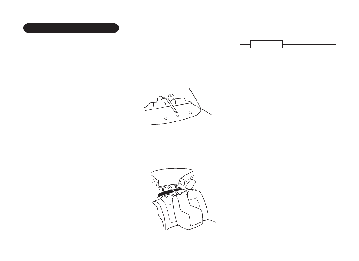
CHILD RESTRAINT
Child restraint installation
Your vehicle has been designed to
accommodate a child restraint on the rear
seat. When using a child restraint, read the
Installation Instructions supplied with the
child restraint and follow the directions for
fitment carefully.
When installing the child restraint, use the
correct anchor bolt. (5/16" bolt)
The anchor bolt must be engaged at least
5 full threads in the anchorage.
If you have any queries regarding the
installation of a child restraint, consult a
Daewoo Dealer.
Anchorage locations
Child restraint anchor fittings have been
installed to coincide with the three rear
seating positions as follows.
Sedan Models:
Anchorages are located at either side and
center of the shelf behind the rear seat.
They are covered with the shelf carpet and
the anchor fitting nuts are welded beneath
the shelf.
Hatchback Models:
Anchorages are located at either side and
center of the lower rear tail member.
WARNING
ï Infants and small children should
never be transported unless they
are properly restrained. Restraint
systems for infants and small
children should be used. Make sure
that the system you purchase
meets applicable safety standards.
Read and follow all the directions
provided by the manufacturer.
ï A child restraint system should be
placed in the vehicle's rear seat.
ï When the child restraint system is
not in use, remove it or fasten it with
a safety belt so that it will not be
thrown forward in the case of a
sudden stop or accident.
Under all circumstances the anchor
bolt must be engaged at least 5 full
threads in the anchorage.
ï Children could be endangered in a
crash if their child restraints are not
properly secured in the vehicle.
(Continued)
1ñ15
Page 20
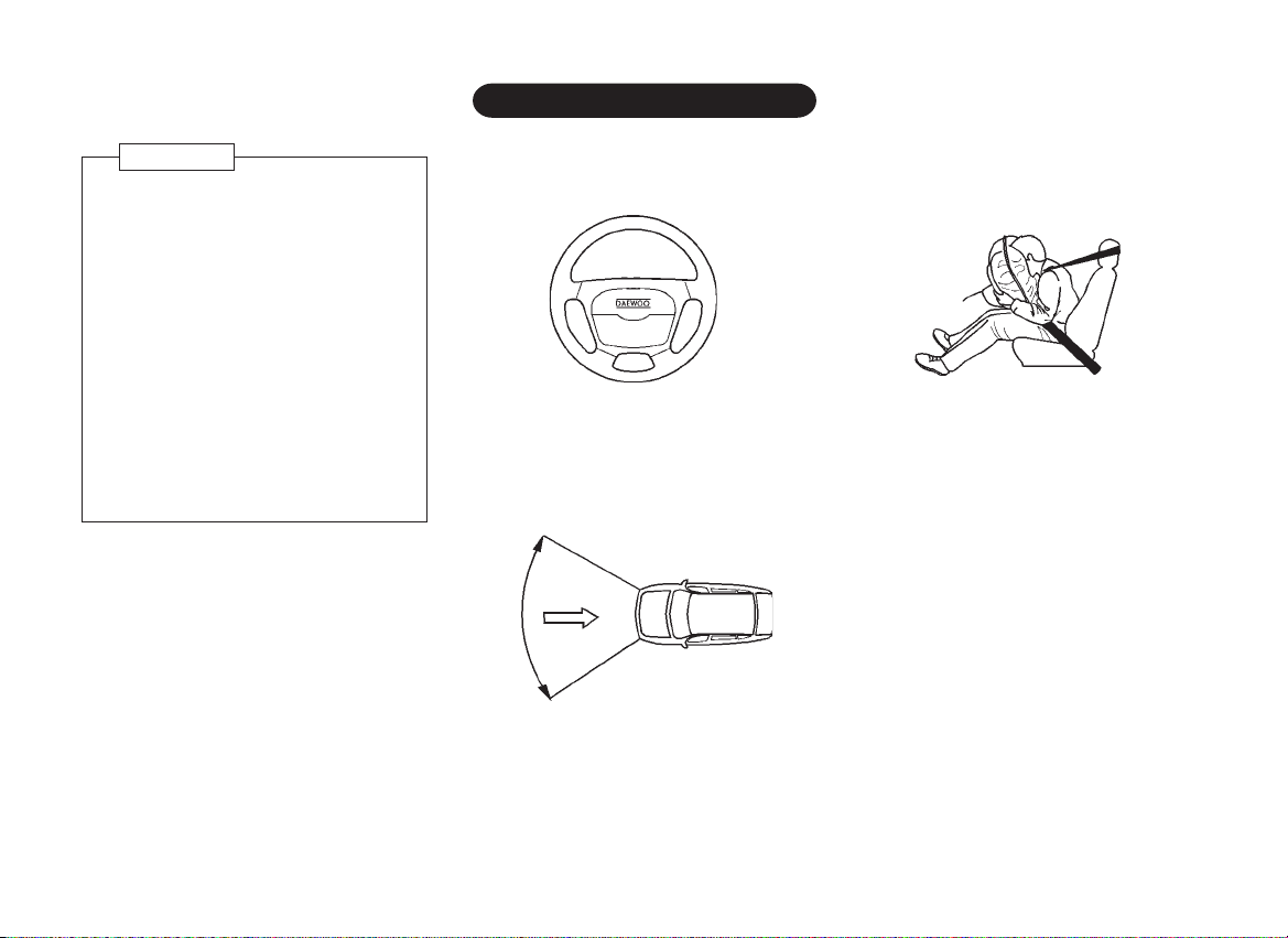
DRIVER'S AIR BAG
*
WARNING
ï Child restraint anchorages are
designed to withstand only those
loads imposed by correctly fitted
child restraints. Under no
circumstances are they to be used
for adult seat belts, harnesses or for
attaching other items or equipment
to the vehicle.
ï If child restraint anchor bolt is
removed from the shelf, the hole
must be effectively sealed with
another suitable bolt to prevent
exhaust gases entering the vehicle
interior.
The air bag is stored in the center pad of
the steering wheel.
The air bag Supplementary Restraint
System (SRS) helps protect the driver's
head and chest against injuries in the event
of a collision.
30∞
30∞
The air bag system activates during severe
collisions which are either frontal or when
the impact angle is up to 30∞ from straight
ahead.
The air bag inflates within milliseconds
during a crash and forms a safety cushion
for the driver.
After the air bag completely inflates, it
immediately deflates so that it does not
interfere with the driver's visibility or ability
to steer and operate other controls.
The air bag inflates with considerable force
and speed. It is therefore important that the
driver's seat and seat back should be
correctly adjusted, for the air bag to be fully
effective. The driver's seat should be
adjusted so that the steering wheel can be
reached with the arms slightly angled.
When the air bag inflates, an operating
noise may be heard and a small amount of
smoke-like gas will be released. The gas is
harmless and does not indicate that there
is a fire.
1ñ16
Page 21

WARNING
WARNING
ï The air bag system will not be
triggered in the event of rear
impact, side impacts, rollovers or
minor frontal collisions. The seat
belts must therefore always be
worn. The air bag system serves to
supplement the seat belt.
ï Never affix anything to or over the
center of the steering wheel, as it
could cause injury when the air bag
is triggered.
ï Do not perform any alterations on
the components of the air bag
system. The system can be
triggered abruptly if it is treated
improperly.
ï The steering wheel and instrument
panel must only be removed by
Daewoo Dealer or Daewoo
Authorized Service Operation.
ï The air bag can be triggered only
once. It must then be replaced by
only a Daewoo Dealer or Daewoo
Authorized Service Operation.
ï Repairs to the steering wheel,
steering column and air bag system
must be carried out by only a
Daewoo Dealer or Daewoo
Authorized Service Operation.
Injuries may result if the air bag is
triggered inadvertently.
ï Do not stick anything on the
steering wheel and instrument
panel or cover them with other
materials. Clean them only with a
dry or a damp cloth. Do not use any
aggressive cleaning agents.
ï The air bag system must only be
disposed of by a Daewoo Dealer or
Daewoo Authorized Service
Operation.
ï The air bag system is designed only
as a supplement to the seat belt.
Seat belt must always be worn and
a sufficient distance kept between
the driver and the driving wheel.
1ñ17
Page 22

STARTING AND OPERATING
2ñ1
Page 23

FUEL RECOMMENDATIONS
Commercially available high-quality fuels are
suitable. Fuel quality has a decisive
influence on the power output, driveability
and life of the engine. The additives
contained in the fuel play an important role
in this connection. You should therefore
use only highñquality fuels containing
additives.
Fuel with too low an octane number can
cause pre-ignition of detonation. Daewoo
cannot be held liable for resultant damage.
Fuel with a higher octane number may be
used.
The larger nozzle used with leaded fuel at
service stations cannot be inserted into the
fuel tank filler neck on vehicles which must
be operated on unleaded fuel only, to avoid
accidental use of leaded fuel.
Do not Use Methanol
Fuels containing methanol (wood alcohol)
should not be used in your Daewoo. This
type of fuel can reduce vehicle
performance and damage components of
the fuel system.
CAUTION
The warranty Policy will not cover
damage of the fuel system and any
performance problems that are caused
by the use of methanol or fuel
containing methanol.
Operation in Foreign Countries
If you are going to drive your Daewoo in
another country, be sure to:
ï Observe all regulations regarding
registration and insurance.
ï Check that a suitable fuel is available.
2ñ2
Page 24
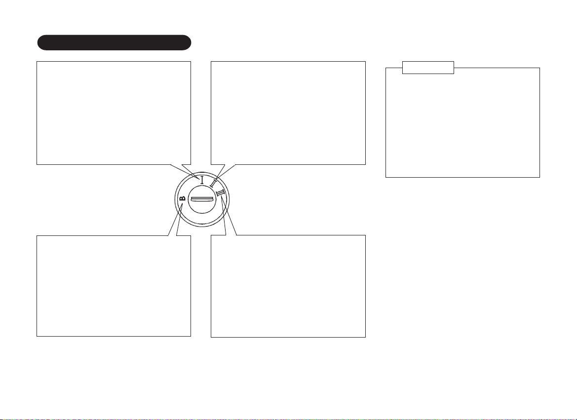
IGNITION SWITCH
OFF
The engine can be turned off without
locking the steering wheel.
LOCK
The steering is locked by removing
the key. Rotate the steering wheel
until lock is engaged.
For easier key operation when
unlocking, move the steering gently
from right to left and turn the key to
the "I" position.
ON
This position turns on the ignition
system and the electrical accessories.
START
This position activates the starter
motor, starting the engine.
Release the key when the engine
starts, and it will be returned to the "II"
position automatically.
WARNING
ï Never remove the key while driving.
If the key is removed, the steering
wheel will lock. This may cause the
driver to lose control of the vehicle
and could result in serious vehicle
damage or personal injury.
ï Never turn the key to "B" or "I"
position when the car is moving.
2ñ3
Page 25
BEFORE STARTING THE ENGINE
STARTING THE ENGINE
ï Make sure the area around the
vehicle is clear.
ï The maintenance items in this manual
should be checked periodically, e.g.,
each time you check the engine oil.
ï Check that all the windows and lights
are clean.
ï Visually inspect the tires for their
appearance and condition. Also check
the tire pressures for proper inflation.
ï Position seat and adjust head restraints.
ï Adjust inside and outside mirrors.
ï Fasten your seat belts and ask all
passengers to do likewise.
ï Check the operation of the warning
lights when the key is turned to the "II"
position.
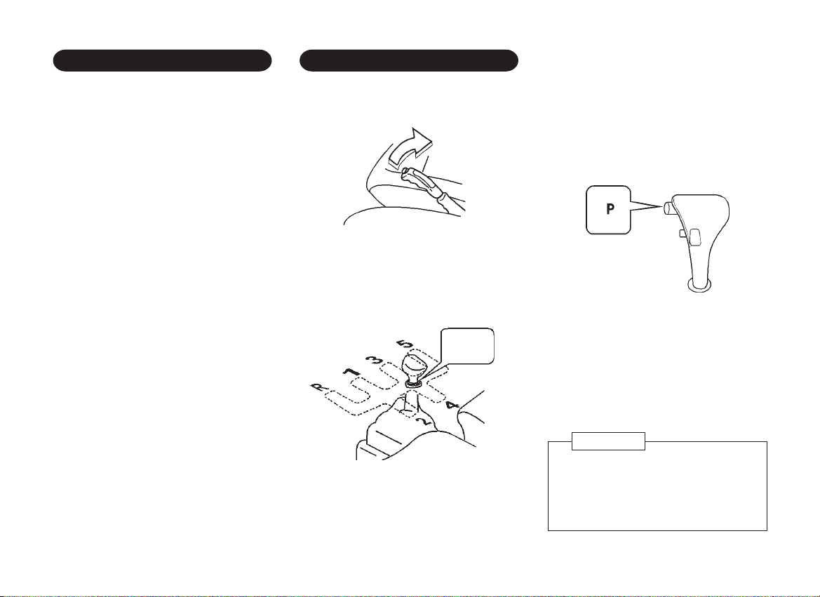
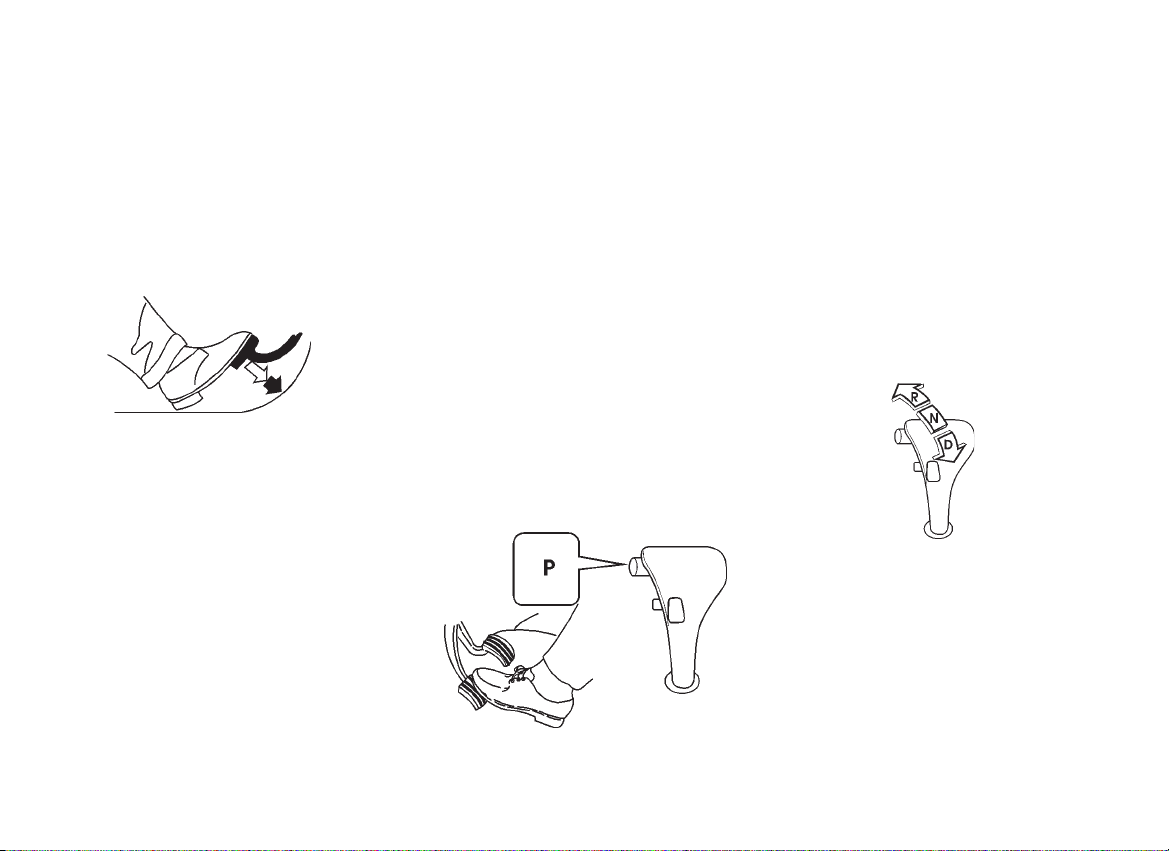
1. Apply the parking brake.
pull
2. Manual transmission:
Move the gearshift lever to "N" (Neutral)
and depress the clutch pedal to the
floor while cranking the engine.
neutral
Automatic transmission* :
Move the selector lever to "P"(Park) or
"N"(Neutral), although "P" is preferred.
The starter is designed not to operate
if the selector lever is in one of the
driving positions.
3. Crank the engine without touching the
accelerator pedal by turning the
ignition key to the "III" start position.
Release the key when the engine
starts.
If the engine starts, but fails to run,
repeat the above procedure.
CAUTION
Do not operate the starter for more than
15 seconds at a time. If the engine does
not start, wait 10 seconds before
cranking again, otherwise the starter
motor could be damaged.
2ñ4
Page 26
DRIVING WITH A MANUAL
4. Warm-up
Allow the engine to idle for at least 30
seconds after starting. Drive at
moderate speed for a short distance
first, especially in cold weather.
NOTE
If the engine has become flooded
during starting, slowly depress the
accelerator pedal fully, hold it in this
position and start the engine.
CAUTION
Extended high speed idling (5 minutes
or more) could produce an excessive
exhaust system temperature that can
damage your vehicle.
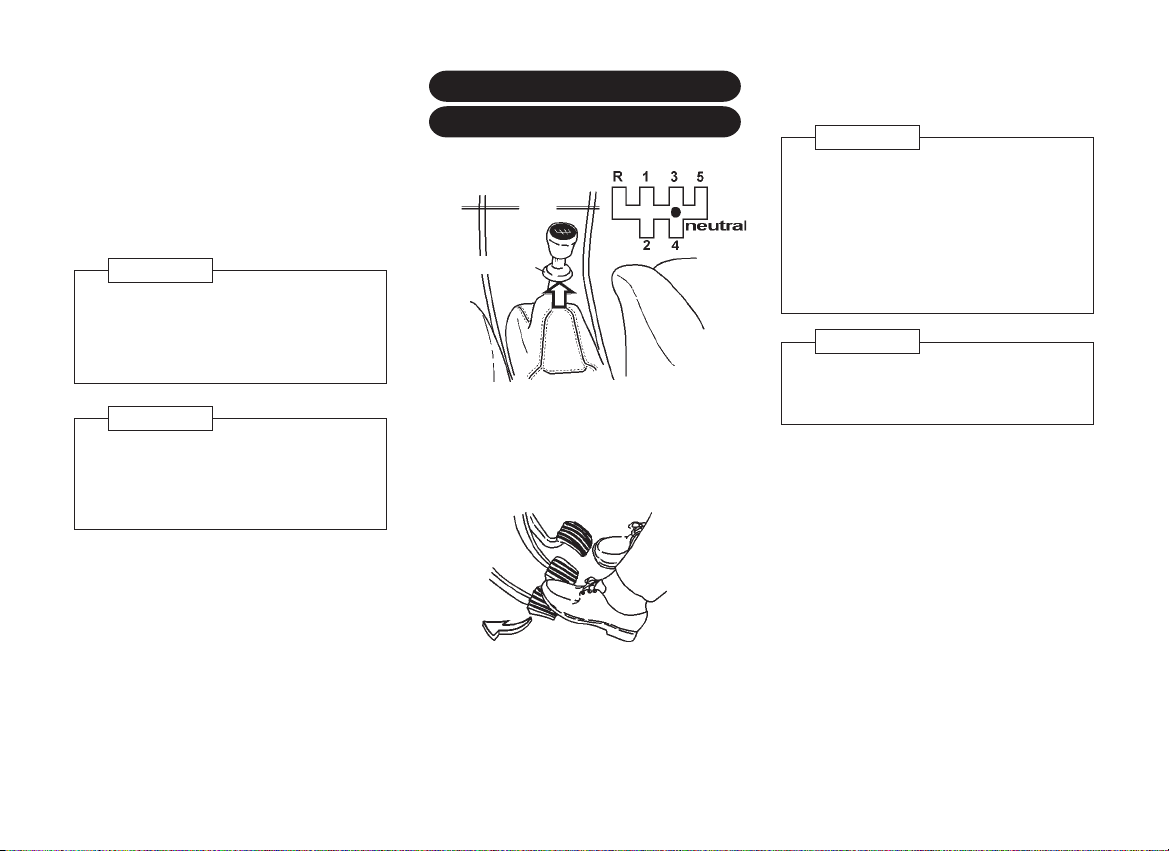
TRANSMISSION
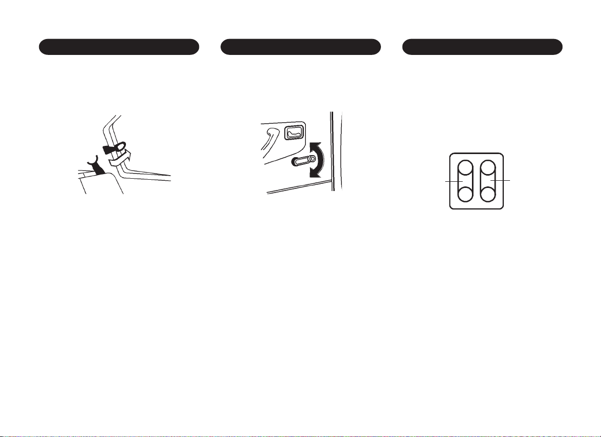
reverse knob
To change gears, fully depress the clutch
pedal. Then move the gearshift lever. After
shifting, release the clutch slowly.
NOTE
ï Do not rest your foot on the clutch
pedal while driving. This may
cause clutch damage.
ï Stop your vehicle completely before
shifting into reverse.
ï To select reverse, be sure to lift
the reverse knob before shifting
into reverse.
CAUTION
To avoid possible damage to the clutch,
do not shift to 1(first) when moving in
excess of 16 km/h.
2ñ5
Page 27
DRIVING WITH A 4-SPEED
AUTOMATIC TRANSMISSION*
release
button
The automatic transmission (4T40-E) in
your Daewoo vehicle is an electronically
controlled four speed transmission. The 4th
gear is an overdrive function.
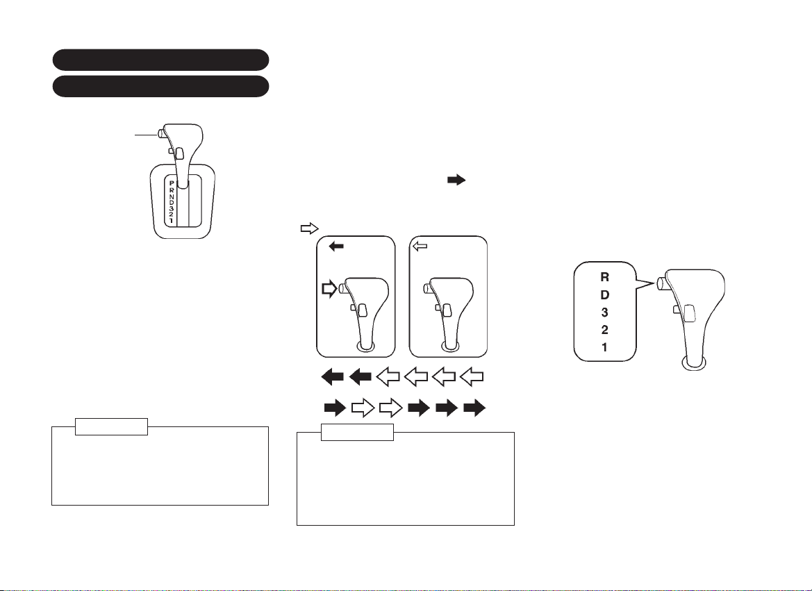
The position of the selector lever is
indicated on the left side of the selector
lever or the automatic transmission selector
position indicator in the instrument panel.
CAUTION
Don't try to shift to P (Park) if your
vehicle is moving. If you do, you could
damage the transaxle. Shift to P (Park)
only when your vehicle is stopped.
Selector lever lock
Push the release button located on the side
of the selector grip when engaging "R"
(Reverse) and "P" (Park) and shifting from
"D" (Drive) to "3", "3" to "2" and "2" to "1" as
indicated by the black arrow " ".
The selector lever can be shifted freely into
any positions indicated by the white arrow
"
".
: push the
button
P R N D 3 2 1
WARNING
Always depress the brake pedal while
shifting from "P" (Park) or "N" (Neutral)
to a forward or reverse gear, to help
prevent the vehicle from moving
unexpectedly when you shift
: Do not
push the button
Starting the car
ï After starting the engine, fully depress
the foot brake pedal before shifting the
selector lever to the "D", "R", "3", "2"
or "1" position. Be sure the vehicle is
fully stopped before attempting to shift
the selector lever into "R" or "P".
1. Keep the foot brake pedal depressed
and shift into a driving gear.
2. Release the parking brake and foot
brake. Depressing the accelerator pedal
slowly will gradually set the vehicle in
motion.
2ñ6
Page 28

Selector lever positions P, R and N
P= Park, with the front wheels locked. To
be selected only with the vehicle
stationary and the parking brake on.
R= Reverse. To be engaged only with the
vehicle stationary.
N= Neutral.
Drive range D
D= The drive position for normal driving
conditions in first to fourth gear.
Fourth gear (the overdrive gear) reduces
engine speed, fuel consumption and the
engine noise level.
After the engine has been started and "D"
selected, the economy driving programme
is always operative.
Drive range 3
3= The drive position for driving conditions
in first, second and third gear.
The transmission remains in third gear even
at high speeds. Do not select "3" above the
maximum permissible speed for this range.
Drive range 2
2= The drive position for first and second
gear, e.g. on winding mountain roads: the
transmission does not shift into third and
forth gear.
Drive range 1
1= The drive position for maximum braking
effect, e.g. when driving down severe
gradients; the transmission does not shift
beyond first gear.
CAUTION
To help prevent transmission damage:
ï Do not depress the accelerator
pedal while shifting from "P" or "N"
to "R", "D", "3", "2", or "1". Always
depress the brake pedal until
shifting is completed.
ï Do not drive in "2" for more than
8 km or at speeds over 90 km/h ,
or you can damage your transaxle.
Use "D" as much as possible.
ï Never shift to "P" or "R" while the
vehicle is in motion.
ï When stopping the vehicle on an
uphill gradient, do not hold the
vehicle by depressing the
accelerator pedal. The foot brakes
should be used for this purpose.
WARNING
ï Do not use the P (Park) position in
place of the parking brake.
ï Turn off the ignition when you leave
the vehicle, even momentarily. Never
leave the vehicle unattended while
the engine is running. Unexpected
and possibly sudden vehicle
movement may occur if these
precautions are not taken.
2ñ7
Page 29
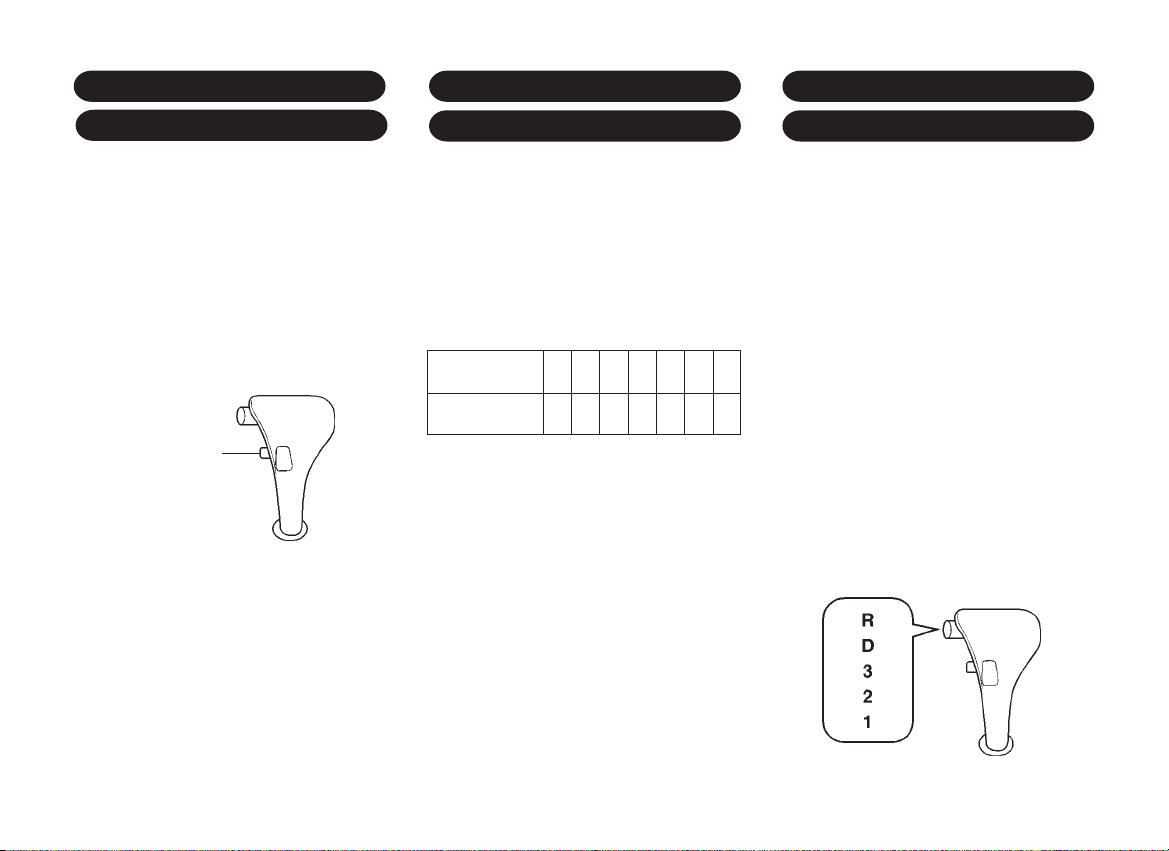
POWER/ECONOMY MODES
DRIVING TIPS FOR 4-SPEEDEMERGENCY OPERATION
SWITCH (4-SPEED AUTO T/M)*
Power mode:
For powerful acceleration or driving up
long slopes, push the power mode switch
on selector lever.
The "PWR" indicator light will come on. The
transmission shifts into the POWER driving
pattern. The transmission will shift at higher
engine revolution obtaining powerful
acceleration when passing or climbing.
power mode
switch
Economy mode:
For normal driving.
This is the most effective and economical
mode for routine, stop-and-go or motorway
driving. The transmission will shift
automatical in this mode.
FOR 4-SPEED AUTOMATIC T/M* AUTOMATIC TRANSMISSION
If the "POWER" indicator flashes
continuously, a fault has occurred in the
TCM (Transmission Control Module) or
electronic part/sensor.
In this situation automatic shifting can be
cancelled and then gear position will be
automatically landed to 2nd gear in drive
position D, 3 and 2 as follows;
Selector lever
position
Gear
position
You must consult a Daewoo Dealer or
Daewoo Authorized Service Operations as
soon as possible when this condition
occurs. The system's integral selfdiagnosis facility allows faults to be quickly
remedied.
PRND3 2 1
PRN2221
Starting the car
After starting the engine and before
shifting into a drive range, depress the
brake pedal since the vehicle will otherwise
start to "creep". Never use accelerator and
brake pedals simultaneously.
For normal driving conditions the "D"
position should be selected.
If the accelerator pedal is depressed gently
and evenly the transmission will shift into
the fuel-saving higher gears at an early
stage. The drive range needs to be
changed manually only in exceptional
cases. Select "3", "2" and "1" only when
automatic shifting up is to be avoided or if
additional use is to be made of the engine
braking effect.
Return to "D" as soon as conditions permit.
*
2ñ8
Page 30
Kickdown
When the accelerator pedal is depressed
beyond its resistance point below certain
speeds, the transmission shifts down into
a lower gear. Full use is made of the engine
power for acceleration.
depress fully
Stopping the car
The selector lever can be left in the chosen
drive range with the engine running.
When stopping on gradients engage the
parking brake or depress the brake pedal.
Do not increase the engine revolutions to
ensure smooth idling while standing if a
drive range has been selected.
Switch off engine if stopping for a lengthy
period, e.g. in traffic jams or at level
crossings.
Rocking the car
If it becomes necessary to rock the car to
free it from sand, mud, snow or a hole,
move the selector lever from "D" to "R" in
a repeat pattern while simultaneously
applying light pressure to the accelerator
pedal. Do not race the engine and avoid
sudden acceleration.
This applies only to the exceptional
circumstances mentioned above.
Engine braking
In order to utilize the engine braking effect
when driving downhill, select drive range
"3", "2" or, if necessary, "1" in good time.
The braking action is most effective in drive
range "1". If drive range "1" is selected at
too high a speed, the transmission remains
in second gear until the shift point for first
gear is reached, e.g. as a result of
deceleration.
Before leaving the vehicle, apply parking
brake, then place selector lever in position
"P" and remove ignition key.
Maneuvering the car
To maneuver the car back and forth during
attempts to park or in garage entrances
utilize the above-mentioned creeping effect.
Regulate your speed by lightly releasing the
brake pedal.
Never press the accelerator and brake
pedals simultaneously.
2ñ9
Page 31

DRIVING WITH A 3-SPEED
AUTOMATIC TRANSMISSION*
The shift lever has six positions.
P (Park) ñ For starting the engine and/or
holding the car in locked position.
R (Reverse) ñ For backing the car.
N (Neutral) ñ An alternate position for
starting engine.
D (Drive) ñ For all normal forward driving.
2 ñ For difficult driving conditions in 1st
and 2nd gear, and engine braking when
descending moderate grades.
1 ñ For extreme driving conditions in 1st
gear.
release
knob
Selector lever lock
Push the release knob located under the
selector grip when engaging "R" and "P"
and shifting from "D" to "2" and "2" to "1" as
:
normal
shift
".
indicated by the black arrow "
The selector lever can be shifted freely
into any positions indicated by the white
arrow "
".
:
pull the
knob
pull
P R N D 2 1
WARNING
Always depress the brake pedal while
shifting from "P" (Park) or "N" (Neutral)
to a forward or reverse gear, to help
prevent the vehicle from moving
unexpectedly when you shift
Engine starting
The selector lever must be in "P" or "N"
position to start the engine.
Starting the car
ï After starting the engine, fully depress
the foot brake pedal before shifting the
selector lever to the "D", "R", "2" or "1"
position. Be sure the vehicle is fully
stopped before attempting to shift the
selector lever.
1. Keep the foot brake pedal depressed
and shift into a driving gear.
R
D
2
1
2. Release the parking brake and foot
brake, then gradually start the vehicle
with depressing the accelerator pedal
slowly .
2ñ10
Page 32

Drive range D
D= Drive position from zero to maximum
speed under the normal driving
conditions.
In range "D" the vehicle starts off in first
gear once the brake has been released
and shifts automatically into second and
third gear. Shifting down is also automatic.
If the accelerator pedal is depressed gently
and evenly the transaxle shifts into the
higher gears earlier than if the vehicle is
made to accelerate rapidly.
Operation of the transaxle and fuel
economy can thus be influenced even
though the system is automatic.
Drive range 2
2= Drive position for difficult conditions in
first and second gear only.
The vehicle will perate only in first and
second gear. Drive range "2" is therefore
particularly suitable for journeys in
mountinous terrain with long climbs and
gradients.
Return selector lever to "D" as soon as
conditions permit.
Drive range 1
1= Position for extreme operating conditions
in first gear only.
The transaxle does not shift beyond first
gear. This range is for extreme operating
conditions such as driving up or down
severe gradients.
Return selector lever to "D" as soon as
conditions permit.
When driving downhill in montainous
territory, it is recommended to select drive
range "2" initially or, if necessary, drive
range "1" in order to utilize the engine
braking effect.
CAUTION
To help prevent transmission damage:
ï Do not depress the accelerator
pedal while shifting from "P" or "N"
to "R", "D", "2", or "1". Always
depress the brake pedal until
shifting is completed.
ï Do not drive in "2" for more than
8 km or at speeds over 90 km/h.
Use "D" as much as possible.
ï Never shift to "P" or "R" while the
vehicle is in motion.
ï When stopping the vehicle on an
uphill gradient, do not hold the
vehicle by depressing the
accelerator pedal. The foot brakes
should be used for this purpose.
WARNING
ï Do not use the P (Park) position in
place of the parking brake.
ï Turn off the ignition when you leave
the vehicle, even momentarily. Never
leave the vehicle unattended while
the engine is running. Unexpected
and possibly sudden vehicle
movement may occur if these
precautions are not taken.
2ñ11
Page 33

DRIVING TIPS FOR 3-SPEED
AUTOMATIC TRANSMISSION
*
Starting the car
After starting the engine and before
shifting into a drive range, depress the
brake pedal since the vehicle will otherwise
start to "creep". Never use accelerator and
brake pedals simultaneously.
The automatic transmission can be almost
always maintained in drive range "D"(1st
to 3rd gear).
If the accelerator pedal is depressed gently
and evenly the transmission will shift into
the fuel-saving gears at an early stage. The
drive range needs to be changed manually
only in exceptional cases. Select "2" and
"1" only when automatic shifting up is to
be avoided or if additional use is to be made
of the engine braking effect.
Return to "D" as soon as conditions permit.
R
D
2
1
Kickdown
When the accelerator pedal is depressed
beyond its resistance point below certain
speeds, the transmission shifts down into
a lower gear. Full use is made of the engine
power for acceleration.
depress fully
Engine braking
In order to utilize the engine braking effect
when driving downhill, select drive range
"2" or, if necessary, "1" in good time.
The braking action is most effective in drive
range "1". If drive range "1" is selected at
too high a speed, the transmission remains
in second gear until the shift point for first
gear is reached, e.g. as a result of
deceleration.
Stopping the car
The selector lever can be left in the chosen
drive range with the engine running.
When stopping on gradients, engage hand
brake or depress brake pedal. Do not
increase the engine revolutions to ensure
smooth idling while standing if a drive range
has been selected.
Switch off engine if stopping for a lengthy
period, e.g. in traffic jams or at level
crossings.
Before leaving the vehicle, apply hand
brake, then place selector lever in position
"P" and remove ignition key.
2ñ12
Page 34

BRAKE
ANTI-LOCK BRAKE SYSTEM*
Rocking the car
If it becomes necessary to rock the car to
free it from sand, mud, snow or a hole,
move the selector lever from "D" to "R" in
a repeat pattern while simultaneously
applying light pressure to the accelerator
pedal. Do not race the engine and avoid
sudden acceleration.
This applies only to the exceptional
circumstances mentioned above.
Maneuvering the car
To maneuver the car back and forth during
attempts to park or in garage entrances
utilize the above-mentioned creeping.
Regulate your speed by lightly releasing the
brake pedal.
Never press the accelerator and brake
pedals simultaneously.
The regular braking system is designed for
braking performance under a wide range
of driving conditions even when the vehicle
is loaded to its full rated vehicle load
capacity.
If the brake pedal can be pressed further
than normal, it may be due to a lack of
adjustment of the rear drum brakes. To find
out if this is the case, drive backward and
forward a few times, applying the brakes
firmly when going in each direction.
Visit your Daewoo dealer if the pedal height
does not return to normal, or there is a rapid
increase in pedal travel. This could be a
sign of brake trouble.
CAUTION
Do not drive with your foot resting on
the brake pedal as this can cause
premature lining wear and possible
damage to the brakes.
(ABS)
The anti-lock brake system controls the
wheels so that they will not lock when
braking abruptly or when braking on a
slippery road. The system detects the
wheel rotation rate and electronically
controls the pressure applied to the brakes.
Slight vibration accompanied by noise
usually occurs while ABS is operating.
Such vibration and noise simply indicates
that the ABS is functioning normally.
If an abnormality occurs in the system, the
anti-lock brake system is cancelled. The
ordinary brakes will operate normally and
the ABS warning light will come on. Consult
your Daewoo Dealer as soon as possible
if this condition occures.
2ñ13
Page 35

PARKING BRAKE
PARKING
Braking with ABS
In an emergency, apply full force on the
brake and clutch pedal simultaneously.
The anti-lock brake system will be activated
immediately, allowing you to retain full
steering control of your vehicle.
We recommend that you familiarise yourself
with this braking technique. However, avoid
taking unnecessary risks.
WARNING
The anti-lock brake system, although
a sophisticated device, cannot prevent
accidents resulting from careless or
dangerous driving techniques.
Ultimately the responsibility for your
safety and that of others rests in the
hands of the driver. Therefore only
through attentive and careful driving
methods can the anti-lock brake
system be fully appreciated.
To set the parking brake, pull the lever up.
pull
To release, pull the lever up slightly, push
the button and lower.
(1) pull
(2) push
(3) lower
See your Daewoo dealer if adjustment of
the parking brake is required.
CAUTION
It is important to check the parking
brake warning light each time you start
the engine. This light will glow when the
engine is running and your parking
brake is applied. Failure to release the
parking brake will result in rapid brake
wear and damage to the braking
system.
1. Firmly apply the parking brake.
2. Manual transmission models:
When parking on a downhill gradient,
place the gearshift lever in the
"REVERSE" position. When parking on
an uphill gradient, place the gearshift
lever in the "1st" position.
Automatic transmission models:
Move the selector lever to the "P"
(PARK) position
3. Turn the ignition key to the "B" (LOCK)
position and remove the key.
4. Lock all the doors after ensuring that
the keys have not been left inside the
car.
CAUTION
ï Things that can burn could touch
hot exhaust parts under your
vehicle and ignite. Do not park the
vehicle over papers, leaves, dry
grass or other things that can burn.
ï Always apply the parking brake fully
before leaving your vehicle.
2ñ14
Page 36

SUGGESTIONS FOR MORE
ENGINE EXHAUST GAS CAUTION
ECONOMICAL OPERATION
Your car's fuel economy is mainly
dependent on your style of driving.
How you drive, where you drive, and
when you drive has an effect on how
many kilometers you can get from a liter of
fuel.
To obtain maximum fuel economy from your
car:
ï Start gradually and accelerate gently.
ï Avoid excessive and unnecessary
idling.
ï Keep your engine properly tuned.
ï Do not race the engine.
ï Use the air conditioning (if equipped)
only when necessary.
ï Slow down when driving on rough
roads.
ï Always keep your tires inflated to the
recommended pressure for longer tire
life and optimum fuel economy.
ï Keep your distance from other vehicles
to avoid sudden stops. This will reduce
wear on brake linings and improve
economy as extra fuel is required to
accelerate back up to driving speed.
ï Do not carry unnecessary weight in the
vehicle.
ï Do not rest your foot on the brake pedal
while driving. This can cause needless
wear, possible damage to the brakes
and poor fuel economy.
ï Always ensure your vehicle is
maintained to the manufacturer's
specification.
(CARBON MONOXIDE)
ï Avoid inhaling engine exhaust gases.
Engine exhaust gases contains carbon
monoxide, which has no color or odor.
Carbon monoxide is a dangerous gas.
It can cause unconsciousness and can
be lethal if inhaled.
ï If at any time you suspect that exhaust
gases are entering the vehicle, have
the vehicle inspected and repaired
immediately by a Daewoo Dealer or
Daewoo Authorized Service Operation.
If it is necessary to drive under such
conditions, do so only with all windows
fully open.
ï To protect against exhaust gases
entering the vehicle, the exhaust
system and body should be inspected:
ñ each time the vehicle is raised for
an oil change.
ñ whenever a change is noticed in
the sound of the exhaust system.
ñ whenever the exhaust system,
underbody or rear of the vehicle is
damaged or becomes corroded.
2ñ15
Page 37

ï Do not operate the engine in confined
areas such as garages or other closed
areas any more than needed to move
the vehicle in or out of the area.
ï When the vehicle is stopped in an
unconfined area for more than a short
time with the engine running, turn off
the recirculation switch to draw the
outside air into the vehicle and set the
fan switch to high speed.
ï Never sit (or leave the children) in a
parked or stopped vehicle for any
extended period of time with the engine
running.
ï Avoid driving with trunk lid or tailgate
open, as exhaust gases could enter
the vehicle. If you must drive with the
trunk lid or tailgate open, close all
windows, turn off the recirculation
switch and open all dashboard
ventilation vents to draw the outside air
into the vehicle, and set the fan switch
to high speed.
2ñ16
Page 38

INSTRUMENTS AND CONTROLS
3ñ1
Page 39

1. Side ventilation vents
17. Air direction control switch
2. Door window defroster vents
3. Head lamp leveling switch*
4. Front fog lamp switch*
5. Rear window defroster with timer*
6. Light switch
7. Steering wheel
8. Instrument clutster
9. Windshield wiper and washer switch,
tailgate window wiper and washer
switch (HB)*
10. Hazard warning flasher switch
11. Rear fog lamp switch*
12. Wiper speed control switch*
13. Digital clock
14. Center ventilation vents
15. Glove box
16. Temperature control switch
18. Radio (AM/FM) and cassette*
19. Cigarette lighter
20. Deposit box
21. Air conditioning switch*
22. Ashtray
23. Fan control switch
24. Reciculation switch
25. Accelerator pedal
26. Horn switch
27. Ignition and starter switch
28. Brake pedal
29. Air bag*
30. Clutch pedal
31. Fuse box
32. Fuel filler door release button
33. Trunk lid release button
3ñ3
Page 40

1. Side ventilation vents
17. Air direction control switch
2. Door window defroster vents
3. Head lamp leveling switch*
4. Front fog lamp switch*
5. Rear window defroster with timer
6. Light switch
7. Steering wheel
8. Instrument clutster
9. Windshield wiper and washer switch,
tailgate window wiper and washer
switch (HB)*
10. Hazard warning flasher switch
11. Rear fog lamp switch*
12. Wiper speed control switch*
13. Digital clock
14. Center ventilation vents
15. Glove box
16. Temperature control switch
18. Radio (AM/FM) and cassette*
19. Cigarette lighter
20. Deposit box
21. Ashtray
22. Air conditioning switch*
23. Fan control switch
24. Recirculation switch
25. Accelerator pedal
26. Ignition and starter switch
27. Brake pedal
28. Clutch pedal
29. Horn switch
30. Fuse box
31. Fuel filler door release button
32. Trunk lid release button
3ñ5
Page 41
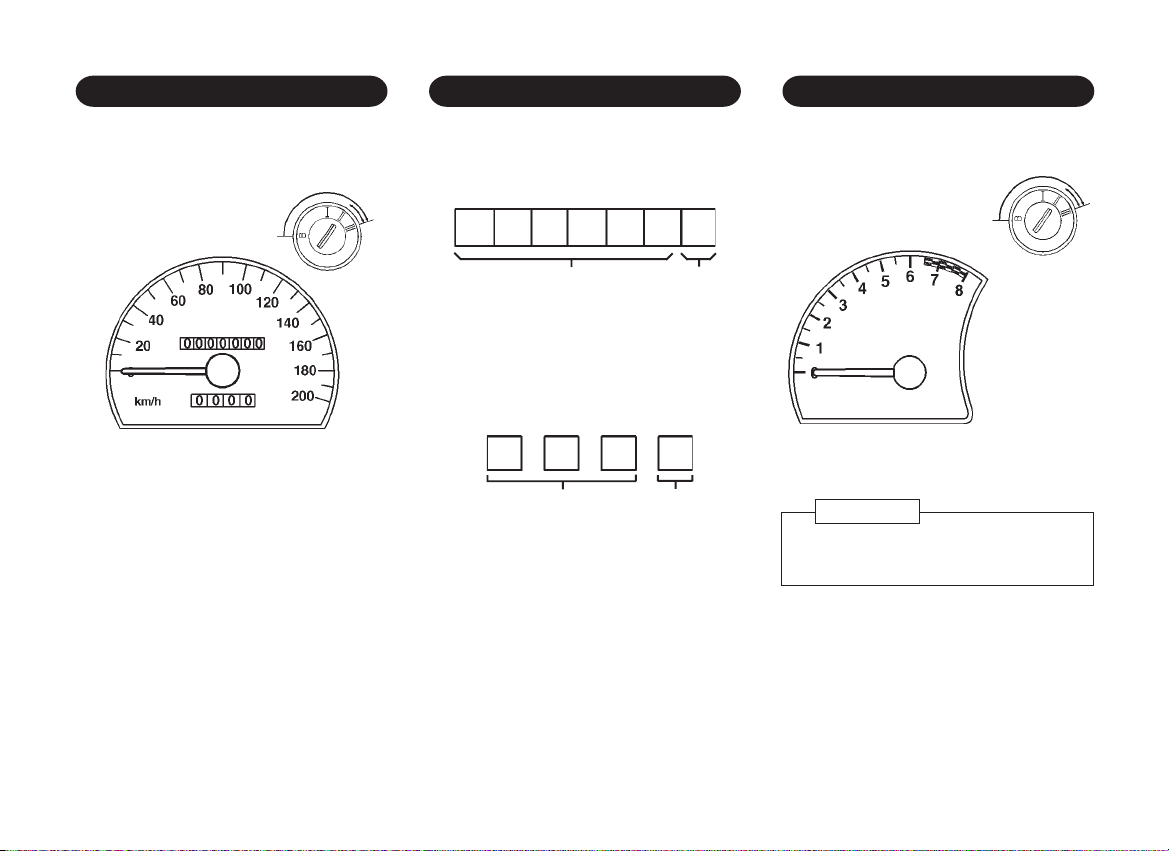
SPEEDOMETER
ODOMETER AND TRIP ODOMETER
TACHOMETER*
speed in kilometers per hour (km/h).
The warning buzzer* will sound when the
vehicle speed exceeds above the specified
speed (only for certain markets).
The odometer registers the accumulated
distance in kilometers.
unit: km unit: 100m
The trip odometer indicates individual
journey distances. To reset, press the
reset button located in the right and lower
area of speedometer.
unit: km unit: 100m
The tachometer indicates engine speed.The speedometer indicates the vehicle
red zone
CAUTION
To avoid possible engine damage do
not rev the engine in the red zone.
3ñ7
Page 42
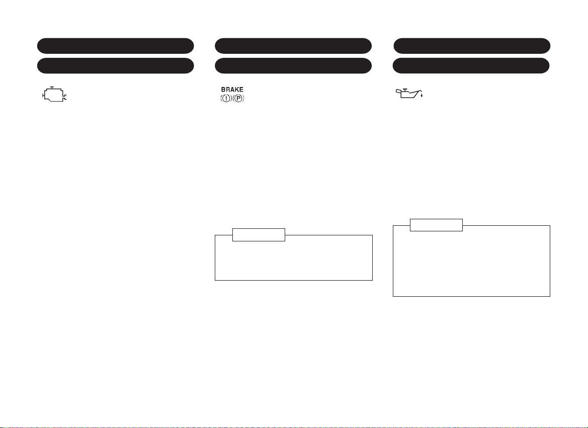
ENGINE CONTROL INDICATOR
BRAKE SYSTEM WARNING
ENGINE OIL PRESSURE
("SERVICE ENGINE SOON" LIGHT)
The engine control indicator
comes on when ignition is
switched on and remains illuminated during
starting. It goes out shortly after the engine
starts to run.
If the indicator illuminates during normal
running, a fault has occurred. The
electronic system switches to an
emergency running program so that driving
may be continued. Consult a Daewoo
dealer or Daewoo authorized service
operation to remedy the fault.
Do not drive for a lengthy period with the
engine control indicator illuminated as this
may increase fuel consumption and impair
the vehicle's driveability.
If the engine control indicator comes on
briefly and then goes out again this is
normal and does not indicate a system fault.
LIGHT
This warning light comes on
when the parking brake is applied
with the ignition on.
Make sure the parking brake is fully
released before driving. The light should
go out.
If the same warning light comes on even
when the parking brake is completely
released with the ignition on, it may
indicate that the brake fluid level in the
reservoir is low.
WARNING
Continued operation of the vehicle in
this condition is dangerous. Have the
brakes repaired immediately.
WARNING LIGHT
The warning light comes on when
the ignition is switched on (as a
check of bulb operation) and should go out
after the engine is started.
If the light comes on while driving, it
indicates that the oil pressure is
dangerously low. Stop the engine
immediately and check the engine oil level.
If the oil level is normal, have the
lubricating system checked at the nearest
Daewoo dealer.
WARNING
Do not run the engine with this light
illuminated.
Do not resume the journey if the oil is
correct, have the engine checked
immediately by a Daewoo dealer.
3ñ9
Page 43

SEAT BELT REMINDER LIGHT*HIGH BEAM INDICATOR
ABS WARNING LIGHT
*
This indicator illuminates when
the headlight high beam is
switched on.
The seat belt warning light comes
on whenever the ignition switch
is placed in the "II" position unless the
driver's seat belt is securely fastened.
Also, the seat belt warning chime will
sound for about 4 to 8 seconds when the
ignition switch is in the "II" position unless
the driver's seat belt is securely fastened.
This warning light illuminates
ABS
when the ignition is switched on
and should go out after the engine has
started.
If the light doesn't come on when the ignition
is switched on, contact your nearest
Daewoo Dealer.
If the light illuminates while driving, stop your
car in a safe place and turn off the engine.
Reset the system by restarting the engine.
If the light comes on again while driving, a
malfunction of ABS system is indicated.
Have the system checked at your nearest
Daewoo Dealer.
Remember that this only means that ABS
is cancelled. Consult your Daewoo Dealer
as soon as possible if this condition
occures ñ your car's brake system will
continue to operate conventionally.
3ñ11
Page 44

LIGHT SWITCH
TURN SIGNAL SWITCH
To turn the lights on or off, twist the knob
on the end of the combination switch lever.
There are three positions:
turn
"OFF" position
All lights are off.
position
Parking, tail, license plate and instrument
panel lights are illuminated.
position
Headlight (low beam) and all the above
lights are illuminated.
Head lamp warning chime*
The chime sounds to remind you to turn off
the lights if the driver's door is opened with
them switched on, when the ignition switch
is turned to the "B" or the "I" position.
NOTE
The asymmetrical low beam increases
the field of vision on the right-hand side
of the lane.
When driving in countries which drive
on the left, the 15∞ section of the
headlamp lenses must have a black
cover strip applied.
Move this lever up or down to the stop
position to engage the turn indicator signals.
right
left
The turn indicator signals will cancel after
the turn is completed then the lever
returns to its normal position.
When lane changing, move the switch part
way to first stop. When released, the
switch will spring back to the off position.
NOTE
To prevent discharging battery, don't
leave the lights on while the engine is
off.
3ñ13
Page 45

WINDSHIELD WASHER SWITCH
TAILGATE WINDOW WIPER
REAR WINDOW DEFROSTER
pull
To spray washer fluid on the windshield,
with the ignition on, pull the lever toward
you and hold it there. The washer fluid is
sprayed onto the windshield and the
windshield wipers are simultaneously
operated for four cycles. When you release
the lever, it automatically returns to the "off"
position.
CAUTION
ï Driving without washer fluid can be
dangerous. Check your washer
fluid level often.
ï In freezing weather, don't use your
washer until the windshield is
warmed. Otherwise the washer fluid
can form ice on the windshield,
blocking your vision.
AND WASHER SWITCH
push
To operate the tailgate window wiper and
washer system, push lever away from
steering wheel.
First position (rest position)=wiper
action.
Second position (rocker position)=wiper
and washer.
The wiper operates when the lever is in
the first position. Washer fluid is sprayed
onto the tailgate window when the lever
is pushed to the second position.
*
WITH TIMER
Pressing this button will switch on the rear
window defroster for appox. 10 minutes
when ignition is in the "II" position and
automatically switch off.
The rear window defroster indicator light
illuminates when the rear window
defroster is operating.
Pressing this button again will switch off
the rear window defroster.
push
CAUTION
Do not use scrapers or any other
sharp instrument, or window cleaners
containing abrasives, on the interior
surface of the rear window or electrical
conductors may be damaged.
3ñ15
Page 46

REAR FOG LAMP SWITCH
*
WIPER SPEED CONTROL
ROOM LAMP
To turn on the rear fog lamps, push this
switch while the front fog lamps are turned
on.
The indicator light illuminates when the
lamps are switched on.
Pushing it again will turn off the lamps.
push
CAUTION
Using the rear fog lamps at night and
in wet weather may dazzle drivers
travelling behind your vehicle and
cause an accident. Use only in severe
fog conditions.
SWITCH
The frequency of intermittent front
wipers can be varied from 4 seconds to
24 seconds by turning the knurled knob
when the wiper is in the "INT" position.
*
The room lamp switch has three
positions.
"ON" position
The light comes on and stays on
regardless of whether a door is open or
closed.
"DOOR" position (between "ON" and
"OFF")
The light comes on when a door is opened.
"OFF" position
The light remains off even when a door is
opened.
3ñ17
Page 47

DIGITAL CLOCK
SUNVISORS
The sunvisors are padded and can be
swung up and down and to the side for
protection of driver and passenger ag-ainst
glare.
1. Front
Digital Clock Adjusting Button
1. H ñ Hour Adjusting Button.
(Ignition II position)
Press H button to adjust hour digits.
Hold the button to adjust rapidly
2. M ñ Minute Adjusting Button.
(Ignition II position)
Press M button to adjust minute digits.
Hold the button to adjust rapidly
3. S ñ Setting Button
(Ignition II position)
To reset the time by the time signal,
press the S button.
For example, if this button is pressed
while the time is between 8:00 and 8:29
the display is set to 8:00. If this button
is pressed while the time is between
8:30 and 8:59, the display is set to
9:00.
8:00 8:29 > 8:00
8:30 8:59 > 9:00
4. DISP ó Display Button
(Ignition Off position)
While pressing D button, the time
appears in the display.
swing down
2. Side
turn
3. Vanity mirror
The vanity mirror is located on the back
of the passenger side sunvisor.
3ñ19
Page 48

LUGGAGE COMPARTMENT
GLOVE BOX
GLOVE BOX ILLUMINATION
*
ILLUMINATION
The lamp will come on when the trunk lid
(or tailgate) is opened.
Open the glove box by pulling the bottom
of the handle upwards.
Close it with a firm push.
pull handle
upwards
Lockable glove box*
To lock or unlock the glove box, insert the
key into the slot and turn it clockwise or
counterclockwise respectively.
WARNING
To reduce the chance of injury in
case of an accident or a sudden stop,
always keep the glove box lid closed
while driving.
The glove box is illuminated when the lid is
in the open position with the ignition
switch placed in the "II" position.
3ñ21
Page 49

OTHER CONTROLS AND FEATURES
4ñ1
Page 50

ENLARGEMENT OF THE
LUGGAGE COMPARTMENT
(HATCH BACK)
The following figures show the method for
enlarging the luggage compartment:
1. Unlock the cover on both sides by
depressing the buttons and lift cover
hinges out of the slots.
2. Unhook the cover from the tailgate,
unlock by depressing pushbuttons on
both sides and lift. Tilt rear edge
downwards. Unlock rear seat backrest
and tilt forwards slightly. Hook cover
into the locking devices. Engage
backrest so that it locks audibly on both
sides.
push
pull
seats.
4. Push front seats forwards. Pull up rear
seat cushion using strap. Hook belt
buckles on backrest. Unlock back rest
and fold down. Place cover behind
front seats.
If you encounter any problems with
enlarging the luggage compartment, your
Daewoo dealer will be pleased to
demonstrate this system.
(1)
(2)
(3)
(4)
3. Hook belt buckles on backrest. Unlock
backrest and fold down onto seat
cushion. Place cover behind front
4ñ2
Page 51

ROOF RACK
ENGINE HOOD
Your vehicle has aerodynamic roof drip
mouldings with installation holes for roof
racks. Avoid damaging the roof when
installing the roof racks.
The installation holes are covered by slides:
press and open by moving in the direction
of the arrow.
Fit the mounting parts on the concealed
drip moulding.
1. To open the engine hood, pull the
release knob to unlatch the hood.
pull
2. Pull the hook up and lift the engine
hood.
3. Hold the engine hood open with the
support rod.
4. Before closing the engine hood,
return the support rod to its clip. This
prevents rattles.
5. Lower the engine hood and make
sure it locks into place by pressing
gently on the front of the hood.
4ñ3
WARNING
ï Before releasing the engine hood
latch, turn off the ignition, remove
the key, place the gearshift lever in
1st or Reverse with manual
transmisssion, in P (PARK) with
automatic transmission, and set
the parking brake fully.
ï If it is necessary to check beneath
the engine hood with engine
running, place the gear selector
lever in N (NEUTRAL) or P (PARK)
and set the parking brake fully.
Unexpected and possible sudden
vehicle movement may occur if
these precautions are not taken.
ï To avoid the possibility of personal
injury, you should always turn off
the ignition and remove the key
before working under the engine
hood unless the particular
procedure specifically requires
other wise. If the procedure
requires you to run the engine
while working under the engine
hood, do not permit any clothing,
such as neckties, handkerchiefs,
near the engine or radiator fan.
They can become entangled in
moving parts and result in
personal injury and damage to the
vehicle.
Also, remove watches, bracelets
and rings.
Page 52

SKI SLEEVE
The ski sleeve is located behind the rear
armrest on saloon models.
You can transport skis or other similar
objects safely without soiling or damaging
the interior of your vehicle.
To use the ski sleeve ;
1. Pull down the rear seat armrest and
open the cover behind it.
2. Push the button located in the upper
side of the opening to open the ski
sleeve lid in the trunk.
Also, the ski sleeve lid can be opened
by pushing the button on the ski sleeve
lid.
*
button
ski sleeve lid
3. Open the trunk and inset your load from
the trunk into the interior.
4. Use the strap on the ski sleeve to
secure the load tightly to the armrest.
NOTE
ï When the ski sleeve is not used,
keep the lid closed.
ï Before folding up the ski sleeve for
storage, make sure it is dry both
inside and outside.
This will help prevent mildew.
POWER SUN ROOF
The power sun roof can only be operated
with ignition "ON".
C
B
A
A: Sun roof lamp
B, C: Sun roof operating switch
To open the sun roof, hold down the "B"
side of the switch.
To close the sun roof, hold down the "C"
side of the switch.
*
4ñ4
Page 53

WARNING
ï Be extremely careful not to have
any part of your body in the sun
roof opening while it is closing.
ï Do not stand up or extend any
portion of your body out of the
opening while driving.
ï Remove water drops, snow, ice or
sand from on top of the sun roof
before opening.
ï Do not place any heavy objects on
the sun roof or surrounding area.
ï Care must be taken when
operating the power sun roof.
There is a risk of injury, particuiarly
for children, and a danger that
articles could become trapped.
ï Make sure that all vehicle
occupants know how to operate
sun roof correctly.
ï Keep a close watch on sun roof
when closing it. Ensure that
nothing becomes trapped in it.
ï Before leaving the vehicle, remove
the ignition key.
4ñ5
Page 54

VENTILATION, HEATING AND AIR CONDITIONING
*
5ñ1
Page 55

VENTILATION AND HEATING
CENTER VENTILATION VENTS
SIDE VENTILATION VENTS
Air mixture system: by mixing cold and
hot air the temperature can be regulated
without delay and thereby held practically
constant at all speeds.
The rate of air flow is determined by the
fan. The fan should therefore be switched
on if required even when driving.
Heating the rear foot area: cold or heated
air is routed to the rear foot area via ducts
underneath the carpet.(*)
Air can be directed into the vehicle via
both center vents. The vents are opened
by means of the regulating wheel. With the
wheel in the resting position, they are
closed.
The air flow can be directed as desired by
tilting and swivelling the fins.
air flow direction adjusting lever
air flow quantity adjusting wheel
Air can be directed into the vehicle via both
side ventilation vents.
air flow direction adjusting lever
air flow quantity adjusting wheel
FRONT DOOR WINDOW
DEFROSTER VENTS
Cooled and warm air will be directed onto
the windshield and onto the side windows
(mainly in the area of the outside mirror).
5ñ2
Page 56

AIR CONDITIONING SYSTEM
*
AIR CONDITIONING SWITCH
*
TEMPERATURE CONTROL
The ventilation, heating and refrigeration
sections make up a functional unit
designed to provide maximum comfort at all
times of year, under any weather
conditions and at any outside temperature.
The refrigeration unit of the air conditioning
system cools the air and removes moisture
and dust.
The heating unit heats the air as required
in all operating modes depending on the
position of the temperature switch. The
quantity of inflowing air is regulated by
using the fan.
This switch turns on and off the air
conditioning.
indicator
Start the engine, turn the fan speed control
switch to the desired speed and press the
air conditioning switch to turn on the air
conditioning. The indicator light will come on
when the air conditioning is on.
To stop the air conditioning, press this
button again.
The air conditioning compressor does not
operate when the fan control switch is at
Off position or the outside temperature is
below approx. 0∞C.
CAUTION
When using the air conditioning while
driving up long hills or in heavy traffic,
watch the engine temperature gauge.
The air conditioning may cause engine
overheating. If the gauge indicates this,
turn off the air conditioning.
SWITCH
cold
(blue)
Temperature switch is used for infinite
adjustment of the temperature of cooled
and warm air as well as that of the
inflowing uncooled outside air.
The left side position: cold (blue)
The right side position: hot (red)
hot
(red)
5ñ3
Page 57

FAN CONTROL SWITCH
AIR DIRECTION CONTROL SWITCH
RECIRCULATION SWITCH
The fan switch provides the speed
control of the blower fan (there are 4 fan
speeds).
This switch allows you to select the
outlet air flow.
(FACE): Air flows from the
center and side
ventilators.
(BI-LEVEL): Air flows from the
center, side ventilators
and the foot outlets of
front seat.
(FOOT): Air flows mainly from
foot outlets of front
seat.
(DEF): Defrosting windshield
and side windows.
Press this switch when driving in dusty
conditions or to avoid traffic fumes, and
when quick cooling or heating is required.
The indicator light will illuminate and
interior air is recirculated inside the
vehicle.
indicator
Pressing it again will draw outside air into
the passenger compartment.
The indicator will go out.
CAUTION
Recirculation switch should not be
turned on for long periods of time. It
may cause the interior air to become
stuff and the windows to fog up.
Driving with the windows fogged up is
dangerous and may cause you to
have an accident.
5ñ4
Page 58

MAXIMUM COOLING NORMAL COOLING
BI-LEVEL
During hot weather and when the vehicle
has been exposed to the sun for lengthy
period. Open window briefly so that warm
air can escape rapidly.
Air conditioning switch: ON
Recirculation switch: ON
Air direction control switch:
Temperature switch: extreme left side
position (blue colored)
Fan switch: speed 4
Normal cooling during interurban and
motorway driving.
Air conditioning switch: ON
Recirculation switch: OFF
Air direction control switch: or
Temperature switch: Blue colored
Fan switch: As required
To be used during transitional periods e.g.
low outside temperature and little
sunshine.
Warmer air will flow into the floor area
and cooler air into the upper zone, when
the temperature switch is adjusted
between cold (blue) and hot (red).
Air conditioning switch: ON
Recirculation switch: OFF
Air direction control switch:
Temperature switch: Between cold (blue)
and hot (red)
Fan switch: As required
5ñ5
Page 59

VENTILATION
Outside air is directed through the center
and side ventilation vents.
MAXIMUM HEATING NORMAL HEATING
Air conditioning switch: OFF
Recirculation switch: OFF
Air direction control switch: or
Temperature switch: As required
Fan switch: As required
Air conditioning switch: OFF
Recirculation switch: ON
Air direction control switch:
Temperature switch: extreme right side
position (red colored)
Fan switch: speed 4
If windows fog up or moisten, turn off the
recirculation switch.
5ñ6
Air conditioning switch: OFF
Recirculation switch : OFF
Air direction control switch: or
Temperature switch: Red colored
Fan switch: As required
Page 60

DEFROSTING
Air conditioning switch: OFF or ON
Recirculation switch: OFF
Air direction control switch:
Temperature switch: As required
Fan switch: As required
WARNING
Do not use the position during
cool operation in extremely humid
weather. The difference between
outside air and the windshield
temperatures could cause the out
surface of the windshield to fog up
and restrict or block your view.
NOTE
Turn the air conditioning on to
improve defroster efficiency.
OPERATING TIPS FOR
COOLING SYSTEM
ï If the car has been parked in direct
sunlight, open the windows before
operating.
ï To clean misted windows on rainy
days, decrease the temperature inside
the car by operating the air conditioning. This is most effective during
rainy weather and high humidity.
ï When driving in heavy traffic areas,
insufficient cooling may occur because
of stopping and slowing down of the
car.
ï When the air conditioning system is not
being used for a month or more, you
must run the engine at idle and turn the
system on for a few minutes once
each week, even during winter months.
This will keep the compressor and
seals properly lubricated and will
prolong the service life of the system.
ï Air conditioning compressor does not
operate when the fan control switch is
at off position or when the outside
temperature is below approx. 0∞C.
5ñ7
Page 61

AUDIO SYSTEM (RADIO AND CASSETTE)
6ñ1
Page 62

RADIO AND CASSETTE
(AKF-9625)
The radio and cassette tape player is
located in the center of the instrument
panel.
Your vehicle is equipped with an audio
system which has an Electronically Tuned
Radio(ETR) and an auto-reverse cassette
tape player.
The radio has seek feature for electronic
station tuning and receives both FM stereo
and AM broadcasts.
The cassette tape player has an autoreverse feature so that it will automatically
reverse and play the other side of the
tape when the cassette player reaches
the end of one side providing continuous
tape playing.
*
NOTE
ï Radio reception is affected by sta-
tion signal strength, distance from a
radio transmitter, buildings, bridges,
mountains and other external influences. Intermittent changes in reception quality are normally caused
by these external influences.
ï Turn the radio off if jumper cables
and booster battery are used to start
your car, to avoid damage to any of
the electronic circuits.
4
2
1. On-off/Volume control knob
(push button)
2. Treble/Bass control knob
(push button)
3. Balance/Fader control knob
(push button)
4. AM/FM band selector button
5. Auto Memory Button
6. Eject button
5
63
7
1112 1314151
7. Cassette slot
8. Fast rewind button
9. Fast forward button
8. 9. Program and FF/REW stop button
10. V.F.D
11. Metal tape selector button
12. Dolby NR button
13. Preset station/memory button
14. Tuning up( )/down( ) button
15. Security warning LED*
10
9
8
6ñ2
Page 63

1. On-off/Volume control knob
(push button)
ï Power on-off
Press this knob to switch on the
audio system and press again to
switch off the audio system.
ï Volume control
Turn this knob clockwise to
increase the volume.
Turn this knob counterclockwise to
reduce the volume.
2. Treble/Bass control knob
(push button)
The bass control knob is used to adjust the bass(low-frequency) sound
quality.
The treble control knob is used to adjust the treble(high-freqency) sound
quality.
ï Treble control
To use the treble control, push on
the knob and allow it to extend. Turn
it clockwise to increase the treble
and counterclockwise to decrease
the treble.
ï Bass control
Pull this knob in the treble contol position until the click sound is heard.
At that position, turn it clockwise to
increase bass tone, counterclockwise to decrease bass tone.
3. Balance/Fader control knob
(push button)
ï Balance control
This knob comes out by pushing it
slightly. At that position, turn it clockwise to increase the volume of right
speakers and counterclockwise to
increase the volume of left speakers.
ï Fader control
Pull this knob in the balance control
position until the click sound is
heard, At that position, turn it clockwise to increase front speaker volume, and counterclockwise to increase rear speaker volume.
4. AM/FM band selector button
Press this button to select FM1, FM2,
AM1 or AM2 band.
Band changes as follows;
> FM1 > FM2 >
AM1 > AM2
5. Auto memory button
When this button is pressed for more
than 2 seconds after selecting band,
auto memory store starts and stations
are automatically searched for in increasing frequency from the frequency
currently received station, and stored
into the preset station buttons 1 through
to 6 in sequence. After storing 6 stations,
this function is automatically resets to
preset scan function, so that the preset
stations are tuned in successively for 5
seconds each.
When the desired station is tuned in,
press the corresponding preset station
button in order to release the preset
scan function.
When you use this auto memory function, the previously memorized stations are erased.
6. Eject button
Press the button to eject the cassette
tape.
6ñ3
Page 64

7. Cassette slot
Switch the radio on and push the cassette fully into the slot with the tape
facing the right side. Mode is automatically transferred from the radio to the
cassette system, the cassette will now
play.
8. Fast rewind button
Press this button to fast rewind the
tape.
Press the "program and FF/REW stop
button" slightly to stop the fast rewind
movement.
9. Fast forward button
Press the button to fast forward the
tape.
Press the "program and FF/REW stop
button" slightly to stop the fast forward
movement.
8. 9. Program and FF/REW stop button
Press 8 and 9 buttons simultaneously
to play the opposite side of tape that
is currently playing.
Also, press 8 and 9 button simulta-
neously to stop fast forward or rewind
movement, and then the tape begins
to play.
10. V.F.D
FM stereo indicator
Dolby indicator
Metal indicator
Tape playing
direction indicator
Frequency indicator
AM/FM band indicator
11. Metal tape button
Preset button
indicator
Press this button when playing a highposition type like a metal tape, a chrome
tape, etc.
The metal tape indicator "MTL" will be
illuminated in the V.F.D.
Switch off for a normal- position type.
12. Dolby NR button
Press this button when playing back
tapes which have been recorded using Dolby noise reduction system. The
Dolby symbol( ) will be illuminated
in the V.F.D. This system improves the
signal to noise ratio of the tape section, resulting in reduced audible "hiss"
during playback.
6ñ4
13. Preset station/manual memory button
You can choose the preset station by
pushing the button for less than 2 seconds with the corresponding number.
If you want to preset a certain station
in the memory:
1. Select a desired band using band
selector button.
2. Choose the desired station using
tuning up/down button.
3. Push one of 6 preset buttons for
more than 2 seconds.
14. Tuning up( )/down( ) button
Press the tuning up or down button to
increase or decrease the frequency.
Manual tuning:
When pressing tuning up or down
button for less than 0.5 seconds, the
frequency of AM band changes 9KHz
each time and the frequency of FM
band changes 50KHz each time.
Seek function:
When pressing the tuning up or down
button for more than 0.5 seconds, the
next station is automatically received in
that direction of frequency.
Page 65

ANTI-THEFT SYSTEM*
The identification card, stamped with the
security code number, is provided with the
vehicle. Keep it in a safe place.
How to enter the security code
1. Connect the audio system to the battery
and turn the ignition switch to the I
position. You will hear the beep.
The audio security system activates
immediately whenever the audio is
disconnected from the battery.
To make the audio system operate again,
you must enter a four-figure security code
with the preset station buttons.
The security warning LED will be flashed
when the ignition key is removed, and will
disappear when the ignition switch is
turned to the I position.
2. Enter a four-figure security code using
the preset station buttons.
3. When the correct code is entered,
you will hear the beep 1 time in 1
second, total 3 times in 3 seconds.
Then, switch on the audio system. It
will now function.
4. If the incorrect code is entered, you will
hear the beep 3 times in 1 second.
To operate the audio system, the
correct code must be entered within 10
minutes.
If the correct code is not entered within
10 minutes, the audio system should be
disconnected from the battery to reset
the audio system.
After reconnecting the audio system to
the battery, repeat the above
procedure(1 to 4).
6ñ5
Page 66
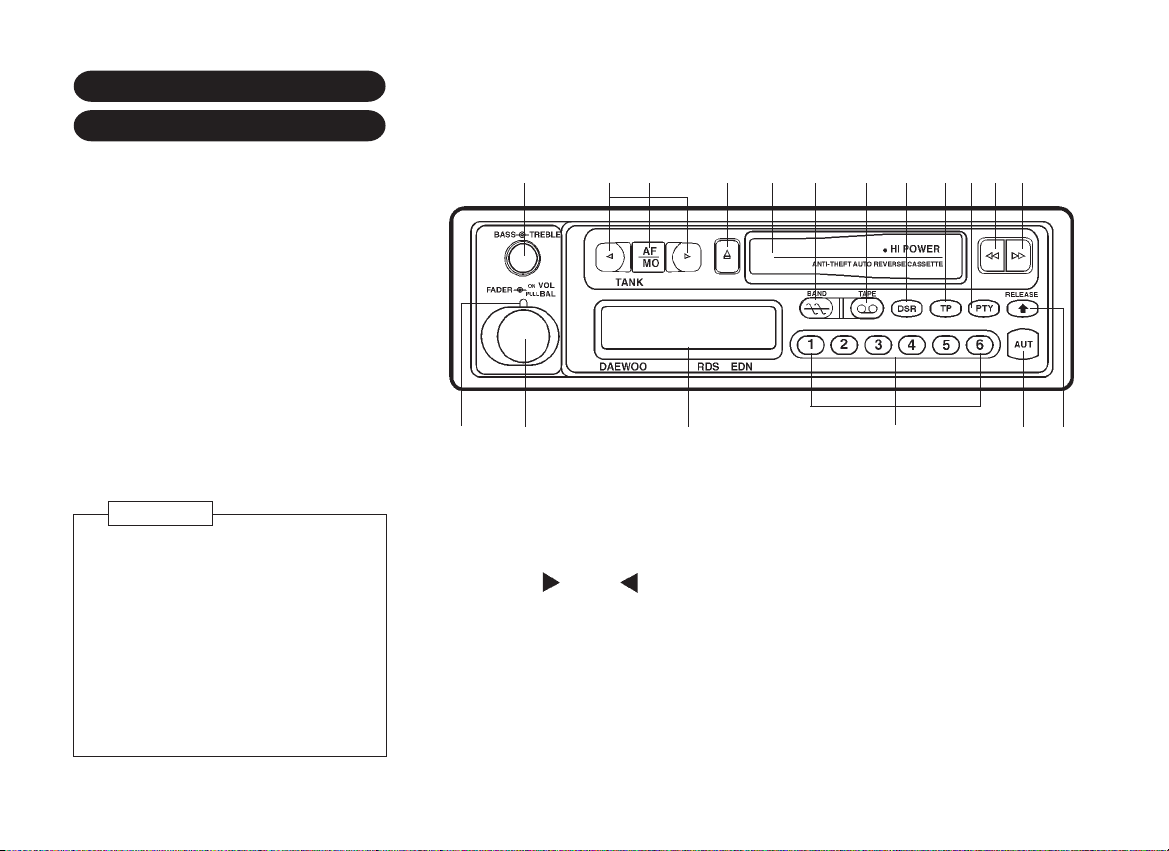
RADIO AND CASSETTE
(AKF-5073K)*
AKF-5073K provides as following controls
and features.
ï FM, MW and LW radio reception
ï R.D.S(PI, PS, AF, TP/TA, EON, PTY)
ï Auto reverse
ï Stereo/mono
ï Positive LCD screen
ï Manual tuning
ï Automatic station seeking
ï Volume/Bass/Treble/Balance/Fader
control
ï Preset memory 6 stations
(FM1, FM2, MW, LW)
ï Warning flashing LED
ï 3 quarter panel detachable for anti-theft
2 1
3 54 6 7 8 9 10 11 13
18
17
12
14
16
15
NOTE
ï Radio reception is affected by sta-
tion signal strength, distance from a
radio transmitter, buildings, bridges,
mountains and other external influences. Intermittent changes in reception quality are normally caused
by these external influences.
ï Turn the radio off if jumper cables
and booster battery are used to start
your car, to avoid damage to any of
the electronic circuits.
1. On-off/volume/balance control knob
2. Fader control knob
3. Bass/treble control knob
4. Tuning up( )/down( ) button
5. AF/mono/stereo select button
6. Eject button
7. Cassette slot
8. Band select button
9. Tape mode select button
6ñ6
10. Display select button
11. TP mode on/off button
12. PTY mode on/off button
13. Fast rewind button
14. Fast forward button
13+14. Program button
15. Front panel release button
16. Auto travel preset button
17. Preset buttons
18. L.C.D
Page 67

REMOVING AND ATTACHING
Before operating your stereo, you should know:
Removing panel
1. Press the release button (15) to unlock front panel.
2. Grasp the right side of the panel and pull toward to arrow
direction carefully.
Front panel
CAUTION
Take care not to put pressure on the display or drop the front
panel.
3. Keep the front panel into the provided plastic carrying case
for protection.
Attaching panel
1. Hold the panel along top and bottom edges.
2. Insert detachable panel straight into main unit(DO NOT TILT).
CAUTION
ï If any of the controls fail to operate, remove and reinstall
the detachable panel.
ï DO NOT touch the gold colored contacts on the
detachable panel and on the main unit since this may
result in poor electrical contact. If the contacts should
become dirty, wipe them with a clean, dry cloth.
ï DO NOT allow such volatile agents as benzine, or
inserticides to come into contact with the surface of the
front panel.
ï DO NOT drop the detachable panel and do not give it
strong impact.
ï NEVER TRY TO DISASSEMBLE the front panel.
ï When leaving the vehicle, always place the detachable
panel inside the provided carrying case and take it with
you. The warning LED will be flashed when the
detachable front panel is removed.
ï Always remove the cassette tape before releasing the
detachable front panel.
6ñ7
Page 68

GENERAL OPERATION
On/off - Volume control knob (1)
Rotate this knob (1) to turn on the unit. You can also regulate the
volume control with this knob. Turn it clockwise to increase volume.
Turn it counterclockwise to decrease volume. Rotate this knob
(1) further counterclockwise to turn off the radio.
Balance control knob (1)
Pull and rotate this knob (1) clockwise to increase the right speaker
volume, counterclockwise to increase the left speaker volume.
You should be able to feel the mid position of this control at this
point, volume from left and right should be equal.
Fader control knob (2)
Rotate the fader control knob (2) counterclockwise to increase
the rear speaker volume, clockwise to increase the front speaker
volume.
Bass/treble control knob (3)
The bass control is used to adjust the bass(low-frequency) sound
quality. Turn it clockwise to increase bass tone, counterclockwise
to decrease bass tone.
The treble control is used to adjust the treble(high-freqency)
sound quality. Pull this knob and turn it clockwise to increase the
treble and counterclockwise to decrease the treble.
Mode select button
It is possible to switch immediately to you desired mode.
Desired mode Pressing button
Radio Band(8)
Tape Tape(9)
* A cassette tape must have been set.
Display select button (10)
Press this button to select the desired display.
Mode Display shift
Radio(FM RDS)
Radio(FM NONRDS, MW)
Tape
FM PTY
PS(Prior display)
Frequency
Tape(Prior display)
PTY PS(Prior display) Frequency
(When pressing the button for more than
1.5 seconds.)
Frequency
Frequency
6ñ8
Page 69

Auto travel preset button (16)
The unit will sean selected band and memorize the strongest 6
stations in sequent from the strongest one.(6FM1, 6FM2, 6MW, 6
LW)
Desired operation
Presetting
stations
Recalling the
AUT
Preset stations
Scanning the
AUT
Preset stations
1) Select the desired band.
2) Press this button for more than 1.5
seconds.
Then the indicator "AUT" and appears on the display.
Scanning will stop automatically and
the first memorized station will be
heard.
Press this button for less than 1.5
seconds. Each time button is pressed,
the station will shift one after another in
the order they were memorized.
1) Press this button for less than 1.5
seconds to select AUT mode.
2) Press the band selector button (8)
for more than 1.5 seconds to receive, in sequence, all the stations
stored in the memory for 5 seconds
each. To stop scanning and listen to
the current receiving station, press
it again.
Procedure
NOTE
ï If all stations are weak, none may be memorized. If this
should occur, "0000" will appear on the display and the
warning tone will be heard. Then the unit will receive the
last station which was received before.
ï If there are fewer than 6 receivable stations, the unit will
memorize all the receivable stations. And the first memorized station will be heard.
ï This unit has RDS functions. So, it does not memorize
the RDS stations of the same PI code.(In FM mode)
L. C. D
6
5
1. TP indicator
2. TP function indicator
3. AUT indicator
4. PTY indicator
5. Band indicator
6. Preset number indicator
1910
7
7. Frequency or station name
indicator, PTY display
8. AF indicator
9. Mono indicator
10. Stereo indicator
342
8
6ñ9
Page 70

TAPE OPERATION
1. Cassette tape slot door (7)
Insert a cassette into this slot door with the exposed tape facing
to the right. Then tape play will begin.
2. Tape mode select button (9)
If a cassette is already inserted, press this button to play the tape.
3. Fast forward
Press the FAST FORWARD button (14) to rapidly advance the
tape. Press the REWIND button to release the fast forward
button.
4. Rewind
Press the REWIND button (13) to rapidly rewind the tape.
Press the FAST FORWARD button to release to rewind button.
5. Program buttons (13+14)
P
ress the FAST FORWARD and REWIND buttons
simultaneously to reverse the cassette direction and to play either
side of the type. The direction when the tape is traveling is
indicated by the arrows on the display. The right side arrow
indicates normal tape direction.
6. Tape eject
Press the EJECT button (6) completely to remove the cassette.
Then the mode changes to the preceding one.
NOTE
Always remove the cassette tape before releasing the
detachable front panel.
RADIO OPERATION
1. Radio mode select button (8)
Press this button to turn on the radio.
2. Band select button (8)
Press this button to select the desired band.
Band shift Pressing time
FM1 < > FM2 Less than 1.5 seconds
FM1, 2 > MW 1.5 seconds or more
>
MW
MW > LW 1.5 seconds or more
3. Tuning up or down buttons (4)
Pressing one of the buttons, tune in a frequency.
Auto(seek)
tuning
Manual tuning
* Auto(seek) tuning ñ The unit will seek in the direction of the
button pressed, and stop on the first strong station.
FM1, 2 Less than 1.5 seconds
To tune up
Press "tuning up
button( )" for less
than 0.7 seconds.
Press "tuning up
button( )" for 0.7
seconds or more
To tune down
Press "tuning down
button( )" for less
than 0.7 seconds.
Press "tuning down
button( )" for 0.7
seconds or more
6ñ10
Page 71

4. Stereo/mono button (5)
If FM stereo broadcasting is too noisy, press this button 1.5
seconds or more to get the indicator "MO".
To return to stereo mode, press it again 1.5 seconds or more.
The indicator "MO" will disappear. If FM stereo broadcast is
received, the indicator " " will appear on the display.
5. Preset buttons (17)
6 stations can be preset on each band.(FM1, FM2, MW, LW)
RDS OPERATION
1. AF mode off button (5)
While the "AF" indicator is shown(AF mode on), once tuned to an
RDS network station, as long as you drive within the area or nation
served by the network, the unit will automatically retune to the
strongest transmitter serving the network, using the PI and AF
codes, when the tuned station gets weaker.
To cancel the mode, press this button.
To make the mode on, press it again to retune to other frequency.
Desired operation
Presetting
stations
Recalling the
preset stations
Procedure
1) Select the desired band and tune to
the station which has to be memorized.
2) Press the desired preset button for
1.5 seconds or more. To preset additional stations, repeat the same
procedure.
Select the desired band and press
the desired preset button.
NOTE
If the tuned RDS station doesn't have AF(List of Alternative
Frequencies) data or the unit cannot receive the AF data for
some reason, the network following will not work when the
tuned RDS station's signal falls below a certain level.
2. TP mode on/off button (11)
Press this button to receive only stations with traffic information
service(TP stations) or EON linked stations with TP stations. The
"TP" indicator appears in the display.
When a TP station is tuned in, the indicator " TP " appears.
ï You may listen to the traffic information in any condition as
follows; you are just playing a cassette or the volume level is
quite low.
ï When receiving the information directly from the station, if the
presently heard traffic information becomes weak, the unit
seeks another TP stations in the network automatically. If it
happens when receiving it through the EON linked station, the
unit returns to the own program of EON linked station automatically.
6ñ11
Page 72

To cancel the mode, press it again.
To cancel the presently heard traffic information and stand by for
the next traffic information from the same station, press it twice
in succession.
NOTE
If you listen to any other station than TP or EON linked
stations for more than 30 seconds with TP MODE ON/OFF
button on, an alarm sounds. To stop the alarm, press this
button again.
3. Preset memory of RDS stations
This unit is equipped with an auto-follow function. Should the
signal of the broadcasting station currently being received begin
to fade out, the unit will automatically tune into another, stronger,
station broadcasting the same program. If this function is triggered
while listening to an RDS station you have called up from the preset
memory, the memorized frequency of the RDS station is changed
automatically to that of the new station the unit tunes in.
4. PI(Program Identification) seek
When the preset button is pressed to call a broadcast station,
auto seek(PI seek) will begin to operate if the broadcast station
called is an RDS station and the reception status is poor. Then,
the same PI station with a stronger signal is received. In like
manner, auto seek(PI seek) will function if an RDS station is
selected when the radio is tuned on.
PTY MODE OPERATION
1. PTY mode on/off button (12)
Press this button to get the PTY mode. The indicator "PTY" appears
in the display. After 10 seconds this mode is canceled
automatically.
To cancel this mode immediately, press it again.
2. Tuning up or down buttons (4)
Desired operation
Selecting an
indicator
(in PTY mode)
PTY search
(in PTY mode)
Press the tuning up or down buttons
within 10 seconds after selecting the PTY
mode. Each time the tuning up button is
pressed the indicator will be switched in
following sequence.
NEWS
EDUCATE DRAMA CULTURE
SCIENCE VARIED MUSIC
POP M ROCK M M.O.R.M.
LIGHT M
SPEECH NEWS.
When the tuning down button is pressed,
the order is reverse.
Press the tuning up or down buttons for
1.5 seconds or more. The unit receives
the station of the indicated PTY code.
If there is no proper station, "NO PTY"
appears on the display. And the unit
receives the station which was received
before the PTY search.
Procedure
AFFAIRS INFO SPORT
CLASSICS
OTHER M
6ñ12
Page 73

3. Preset button(15)
Desired operation
PTY search
(in PTY mode)
Memorizing PTY
(in PTY mode)
Procedure
ï Press the desired preset button.
ï The memorized PTY is indicated on
the display and the unit receives the
station of the indicated PTY code.
ï The initial setting of the preset but-
tons are as follow.
1 . .. . NEWS
2. ... INFO(information)
3 . . . . SPORT
4. ... POP M(Pop Music)
5. ... ROCK M(Rock Music)
6. ... CLASSICS(Serious Classic)
If there is no proper station, "NO
PTY" appears on the display. And the
unit receives the station which was
received before the PTY search.
1) Press the tuning up or down buttons to select the desired PTY
indicator.(See 2 selecting an indicator)
2) Press the desired preset button for
1.5 seconds or more.
USING THE RDS FUNCTIONS
The RDS(Radio Data System) is a digital information system
developed by the EBU(European Broadcast Union). Pick-a-backed
on normal FM broadcasts, RDS offers a variety of information
services and automatic retuning functions for RDS compatible car
stereos.
RDS digital data includes various data:
PI ñ Program identification
Recognizes the country code and the program of the channel.
PS ñ Program service name
The name of the channel is shown in the display.
AF ñ List of alternative frequencies
A list of alternative frequencies with the same program contents
to tune automatically to the stronger station which broadcasts the
same program, using PI and AF.
TP ñ Traffic program
Recognizes channels with traffic information.
TA ñ Traffic announcement
Detects traffic information broadcast via the channel.
PTY 31 ñ Alarm code
Detects alarm announcement via the channel (catastrophe alarm).
REG ñ Regional change
Change to regional stations.
EON ñ Enhanced other networks
Makes the traffic announcement for stations without traffic
decoder possible.
6ñ13
Page 74

RDS functions of this unit
This unit has the following functions for making use of RDS data.
ï Station name display using PS data.
ï AF(Altermative Frequencies) reception which automatically
tunes to the stronger station which broadcasts the same
program, using PI and AF data.
ï Automatic reception of traffic information broadcasts using TP/
TA and EON data.
ï PTY function which searches the stations of the same PTY.
Network/station name display
When you switch on the radio and select FM bands, the unit enters
the RDS mode automatically.
When you tune into an RDS station with manual or seek tuning,
the frequency display changes to the network/station name
display by means of the PS code RDS data.
NOTE
ï The RDS function of this unit uses RDS data transmitted
along with FM broadcasts. It does not work in the MW
and LW bands.
ï The RDS function may not work properly in the areas
where test transmissions are being conducted.
IMPORTANT
As a result of the PS function the station display changes
over to frequency display during the manual or automatic
search for a station.
AF-function(network following)
The unit retunes to the stronger alternative transmitter in the list
of alternative frequencies(AF). The display indicates "AF" as
confirmation in the display (18). Thus a motorist can keep listening
to the same program.
Example: If there are the following network broadcasting stations,
the reception frequency automatically changes from 98.5 MHz to
107.5 MHz to 96.0 MHz to 102.5 MHz, but a motorist can keep
listening to the same program while driving from point A to point
B.
AF-reception
The AF-function is only possible with FM. If the AF-function is
turned on the radio has tuned into an RDS transmitter and it will
automatically find the best transmitter in the particular chain of
transmitters as soon as reception starts to get worse, as long as
you are still driving within the areas of the particular areas. The
display shows the indicator "AF" in the display (18).
6ñ14
Page 75

ï Sometimes it may seem that the radio has gone off for a short
while. There is no fault the radio is merely checking the quality of other signals on the AF-list. If muting disturbs turn off
the AF-function.
ï When the radio switches over to an alternative frequency it
will go quiet for a moment, because it first has to check out
the accuracy of the PI data for the new frequency.
ï If you leave a reception area and there is no alternative AF-
frequency, the indicator "AF" flashes in the display .
TA-traffic announcement
When depressing the TP mode on/off button (11), the TA-function
is activated. The indicator "TP" then appears in the display. Pushing
the tuning up or down buttons is set in the traffic information
mode and searches for a station which broadcasts traffic
information. As soon as this station is reached, " TP " appears
with "TP" in the display. If reception is poor, you will hear a
warning tone telling you to start a new search.
ñ Don't activate the TP-function in an area or a country where
the RDS traffic information service is not available, as seek
tuning and preset scan will not pick up any stations.
Then after 30 seconds an alarm sounds, warning the driver
to turn off the TP function.
ñ RDS traffic information coverage is inherently narrower than
normal FM stereo signals or ARI traffic information Germany,
Austria and Switzerland. Then after 30 seconds, an alarm
sounds, warning the drive to tune another TP-station.
PI-seek
PI-automatic seek starts automatically, if you want to recall a preset
button, when its reception is weak. If the radio doesn't find a
station with the same PI-code you hear the station, which you
heard before.
PTY 31 alarm code
During production, your radio has been fitted with an RDS function
- a PTY 31 alarm system.
This means that you not have to activate this function separately.
If a radio station sends on alarm signal your radio automatically
tunes in to this station the duration of the alarm message, whether
you are listening to the radio or the cassette. The volume for the
alarm message is present in the factory.
What is EON?
EON(Enhanced Other Network) is a new RDS service provided
by certain station networks. Even if you are tuned in to an RDS
station which does not give traffic news, e.g. a classical music
programme, you can still get the traffic news by pressing key TA
9, which tunes your radio in to the traffic news. If another RDS
transmitter now starts to broadcast traffic news, your radio
automatically switches to this station for the traffic news. When
the traffic news is finished, it switches back to the station you
were on before.
If seek starts automatically by turning on the TA-function, the
chosen station doesn't have EON-signals.
6ñ15
Page 76

NOTE
Thanks to this new RDS function, the alternative frequency
lists of the selected chain of stations is automatically updated
and this ensured that there is always an instant automatic
search of the best RDS stations in all programs of the
particular chain of stations.
ANTI-THEFT SYSTEM*
The identification card, stamped with the security code number,
is provided with the vehicle. Keep it in a safe place, not in the
vehicle.
Programming the code:
1. Connect the audio system to the battery and turn the ignition
switch to the I position. "CODE" is shown in the display.
2. Press the preset button no. 1 until the correct first figure is
shown on the display.
3. Press the preset button no. 2 until the correct second figure
is shown on the display.
4. By the same method, enter the correct third and fourth figures,
using the preset buttons 3 and 4.
5. After entering the correct four-figure security code, press the
"AUT" button (16). "CODE OK" is shown on the display and
the equipment is ready for use.
The audio security system activates immediately whenever the
audio is disconnected from the battery. It is protected by a security
code.
To make the audio system operate again, you must enter a fourfigure security code with the preset station buttons.
Wrong code:
If you press the wrong code by mistake, "ERROR 1" is shown on
the display. After this, "CODE" is displayed again. Then repeat the
above proceduce from 2 to 5.
A total of ten coding attempts can be made and then the time
between each new attempt is doubled. If you forget the security
code, consult your Daewoo Dealer.
6ñ16
Page 77

POWER ANTENNA
*
CARE AND MAINTENANCE
The antenna will automatically extend when
the radio mode is switched on, and
retract when the radio mode is switched
off, or cassette mode is switched on.
CAUTION
Before switching the radio on or off
make sure that there is no one near
the antenna while it is retracted or
extened.
OPERATING TIPS FOR
AUDIO SYSTEM
When the ignition switch is placed in the I
position, the audio system can be switched
on by pushing the power button.
If the ignition switch is turned to B position
while the audio system is operating and the
key is not removed from the ignition switch,
the audio system will continue to function.
When the key is removed, the audio
system is switched off automatically.
1. We recommend that tapes below C90(the playing time: 90 minutes) be
used. C-120 tape is extremely thin and
its use should be avoided if at all possible.
2. If a loop of tape has formed, it must be
taken up by turning one of the spools
with a suitable object such as ballpen
or pencil.
3. Store cassettes where they will not be
exposed to high temperature, direct
sunlight, magnetic fields, tape abrasion
or dirt.
4. Never leave cassette inserted in the
operating position with the tape player
inoperative.
5. Clean the head of the tape player
carefully with a cotton applicator
soaked in alcohol. If the tape player
is used for more than one hour every
day, the head should be cleaned once
or twice a month.
If it is used very infrequently, you only
need to clean the head every two or
three months.
6. Don't oil revolving parts of the tape
player.
7. Keep tapes in their plastic cases when
not in use.
6ñ17
Page 78

IN CASE OF EMERGENCY
7ñ1
Page 79

SPARE WHEEL, JACK AND WHEEL CHANGING
VEHICLE TOOLS
The spare wheel, jack and vehicle tools
are accommodated in the luggage/load
compartment.
The spare wheel is retained by a bolt under
a floor cover.
The jack and vehicle tools are located
next to the spare wheel in a special
compartment.
WARNING
Storing a jack, a tire, or other
equipment in the passenger
compartment of the vehicle could
cause injury. In a sudden stop or
collision, loose equipment could strike
someone. Store all these in the proper
place.
In order to reduce the chance of possible
injuries when changing a wheel, note the
following procedure and observe all
references:
ï Park on a firm, level surface wherever
possible.
ï Turn the ignition switch off and remove
the ignition key.
ï Switch on the hazard warning
flashers and apply the parking brake.
Place the automatic transmission
selector lever in position "P", or with
manual transmission engage first gear
or reverse.
ï Set up warning triangle.
ï With a wedge block or any available
block of wood or a rock, block the
wheel diagonally opposite the wheel to
be changed.
ï Use the jack only when changing
wheels.
CAUTION
ï Never crawl under a jacked-up
vehicle.
ï Never start or run the engine while
the vehicle is supported by jack.
ï No person should remain in a
vehicle that is being jacked.
ï Do not jack up the vehicle on an
inclined surface.
ï Do not raise the vehicle with the
jack in a location other than under
the notch closest to the wheel you
are changing.
ï Do not get bodily under a vehicle
that is supported only by a jack:
use vehicle support stands.
NOTE
ï To eliminate the possibility of the
jack, jack handle and tools rattling
while the car is moving, stow them
properly.
ï When cleaning the plastic wheel
covers, wash with plenty of water
and use a sponge, chamois of soft
cloth to prevent scratching or
damaging the finished surface.
ï Call a garage or motoring service
for assistance where conditions
are not satisfactory for jacking the
car or if you are not confident of
completing the task safely.
7ñ2
Page 80

PROCEDURES
ï Pry the wheel cover off with the lug
wrench.
ï Loosen the wheel bolt one turn each
with the wheel wrench, but do not
remove any bolt until the wheel has
been raised off the ground.
ï Turn the jackscrew clockwise four
turns and place the jack at the front or
rear jacking location closest to the
wheel you are changing. Place the jack
under the jacking point at the side sill
as shown in illustration.
JACK SPECIFICATION
Type
Maximum
working load
Grease type
Grease class
Cantilever
600kg
Lithium
1 (NLGI)
WARNING
ï Use this jack only with cars with
which the jack fits and that are not
heavier than the lifting limit of the
jack.
ï Make sure that the car is braked that
it cannot roll off the jack when it is
lifted.
ï Fix the jack in the correct position
marked or given by the manufacturer
of the vehicle. Never fix it in other
part of the vehicle.
ï Fix the jack in such a way that your
hand is never under the car during
the operation of the jack.
ï When installing the jack for lifting
the car, it should be perpendicular
to the ground.
ï If you wish to go (work) under the car
when it is lifted, please support the
car additionally with other means
(wooden block for example).
7ñ3
Page 81

STARTING THE ENGINE
ï Raise the vehicle by turning the crank
handle clockwise until the jack lifting
head fits firmly into the notch and the
wheel is off the ground (about 3 cm).
Do not raise the vehicle more than
necessary.
ï Remove the wheel bolts by turning
them counterclockwise and then
remove the wheel.
ï Mount the spare wheel in position and
tighten the wheel bolts hand-tight by
turning clockwise.
ï Turn the jack handle counterclockwise
and lower the vehicle to the ground.
Tighten the wheel bolts firmly in "X"
pattern (1-2-3-4).
ï Install the wheel cover.
CAUTION
ï Incorrect wheel bolts or improperly
tightened wheel bolts can cause
the wheel to come off. Be sure to
use the correct wheel bolts.
ï Remove any corrosion on wheel
mounting surface.
ï Never use oil or grease on bolts.
WITH JUMP LEADS
A car with a discharged battery may be
started by transferring electrical power
from a battery in another car.
This may be dangerous and any deviation
from the following instructions could lead
to personal injury or property damage
resulting from battery explosion, battery
acid or electrical (short circuit) burns as
well as to damage to the electrical systems
in both vehicles.
ï Never expose the battery to naked
flames or sparks.
ï Do not allow battery fluid to come into
contact with eyes, skin, fabrics or
painted surfaces. The fluid contains
sulfuric acid which can cause injuries
and damage in the event of direct
contact.
ï To lessen the risk of injury wear eye
protection when working near any
battery.
ï Make sure that the battery providing the
jump start has the same voltage as the
battery in your car (12V).
ï Do not disconnect the discharged
battery from the vehicle.
ï Switch off all unnecessary electrical
7ñ4
Page 82

loads.
ï Do not lean over the battery during
jump starting.
ï Do not allow the terminals of one lead
to touch those of the other lead.
ï Apply the parking brake. Place gear
shift lever in neutral (Automatic
transmission: set selector lever to "P").
Connect leads in the order shown in
the picture:
1. Connect one end of the first jump lead
to the positive terminal of the battery
providing the jump start (identified by
"+" sign on battery case or terminal).
2 Connect the other end of this lead to
the positive terminal of the discharged
battery ("+" sign).
3. Connect the first end of the other jump
lead to the negative terminal of the
battery providing the jump start
(identified by "ñ").
4. Connect the other end of the second
jump lead to ground on the other vehicle
e.g. engine block or screw connection
in engine suspension.
Do not connect lead to negative terminal
of discharged battery!
The connection point should be as far
away from the discharged battery as
possible.
Route the leads so that they cannot
catch on rotating parts in the engine
compartment.
5. The engine of the vehicle providing the
jump start can be allowed to run during
starting.
Attempts to start the engine of the
vehicle with the discharged battery
should be made at intervals of one
minute and should not last longer than
15 seconds. After starting, allow both
engines to idle for approx. 3 minutes
with the leads still connected.
6. Turn off the engine, then carefully
disconnect the jump cables in the
reverse order of connection.
CAUTION
If you leave the audio system on, it
could be badly damaged.
Vehicles with catalytic converter or
automatic transmission must not be
started by pushing or towing. This may
cause catalytic converter or
transmission damage.
7ñ5
Page 83

TOWING THE VEHICLE
If towing is necessary, contact a Daewoo
outlet or professional tow truck service.
Proper lifting and towing precedures are
necessary to prevent damage to the
vehicle.
When towing the vehicle by wheel lift:
ï Switch on hazard warning flasher of
both vehicles.
ï Set the ignition switch in the "I (OFF)"
position.
ï Place the gear shift lever in neutral
(manual transmission) or the selector
lever in N (automatic transmission).
ï Release the hand brake.
ï Vehicles should be towed with the
driving (front) wheels off the road.
CAUTION
Never tow the vehicle from the rear with
front wheels on the road as this may
cause the serious damage to the
transmission.
If excessive damage or other
conditions prevent towing the vehicle
with driving (front) wheels off the road,
always use a towing dolly under the
driving (front) wheels.
7ñ6
Wheel dolly
CAUTION
Do not tow with sling-type equipment.
Use wheel lift or flat bed equipment.
Emergency towing
For emergency towing, e.g., when a
towing service is not available, your vehicle
is equipped with the towing hooks under
the front and rear of the vehicle for use
with a tow rope.
When towing the vehicle with the tow
rope:
ï Secure the rope to the towing hook
under the front of the vehicle as tight
as possible.
ï Switch on the hazard warning flasher
of both vehicles.
ï Place the gearshift lever in neutral and
release the hand brake.
ï Set the ignition in the ON (II) position to
release the steering column lock and to
permit the operation of brake lamps,
horn and windscreen wipers.
ï Only the driver should be in the towed
vehicle to steer it and operate the
brakes.
ï To prevent the entry of exhaust fumes
from the towing vehicles, close the
windows and turn on the recirculation
switch.
Page 84

ROCKING THE VEHICLE
CARAVAN OR TRAILER
ï Drive off slowly and avoid jerky
movements.
NOTE
ï More brake pedal pressure is
necessary when braking since the
brake servo unit is operative only
when the engine is running.
ï On vehicles with power steering,
greater steering force is necessary
since this unit is operative only
when the engine is running.
CAUTION
ï The towing hook should be used
only in an emergency situation.
ï When towing the vehicle with a
rope, the vehicle should be towed
only facing forward.
ï Vehicles with automatic
transmission should not be towed
with a rope. They should be towed
with the front wheels off the ground
or carried by a flat bed truck.
ï Never attempt to tow the vehicle
with a rope if the wheels,
transmission, axles, steering or
brakes are damaged.
If it is necessary to rock the vehicle to free
it from snow, sand or mud, move the
selector lever on an automatic transmission
models from "D" to "R" in a repeat pattern
while depressing the accelerator gently.
(On manual transmission models, move the
gearshift lever from first to reverse gear.)
Do not race the engine. If you are still stuck
after a minute or two of rocking, have the
vehicle pulled out to avoid overheating and
possible damage to the transmission.
CAUTION
Do not spin the front wheels
excessively, as this may cause
personal injury and/or premature failure
of the driveline components.
TOWING
Your vehicle is designed primarily as a
passenger vehicle therefore handling,
braking, durability and economy will be
affected by towing a caravan or trailer.
Your safety and satisfaction depend upon
proper use of correct equipment. Also, you
should avoid overloading and other
abusive use.
The maximum loaded trailer weight you can
pull with your vehicle depends on your
intended use and what special equipment
has been installed on it. Before attempting
any towing, ensure that the correct
equipment is fitted to your vehicle.
Your Daewoo Dealer will help supply and
install towing equipment to suit your
requirement.
7ñ7
Page 85

Caravan/Trailer Loading
To load your caravan/trailer properly, you
must know how to measure gross caravan/
trailer weight and caravan/trailer tongue
weight. Gross caravan/trailer weight is the
weight of the caravan/trailer plus all cargo
in it. You can measure gross caravan/trailer
weight by putting the fully loaded caravan/
trailer on a vehicle scale.
Caravan/trailer tongue weight is the
downward force exerted on the hitch by
the caravan/trailer coupler, with the
caravan/trailer fully loaded and the coupler
at its normal towing height. This weight can
be measured using a bathroom scale.
The weight of your loaded caravan/trailer
(gross caravan/trailer weight) should never
exceed the values in the chart below.
The maximum permissible caravan/trailer
tongue weight is 75 kg.
The permissible caravan/trailer loads are
valid for gradients up to max. 12%.
(unit: kg)Maximum Towable
Weight
MPFI
DOHC
Type Tongue
With Brake
Without Brake
With Brake
Without Brake
Caravan/
trailer
860
430
860
400
75
75
75
75
When the trailer/caravan has been coupled,
the permissible rear axle load for the fully
loaded towing vehicle (including
occupants) must not be exceeded.
NOTE
Total gross vehicle weight with caravan/
trailer must not exceed the Gross
Vehicle Weight Rating (GVWR) of the
vehicle. The total gross vehicle weight
is the weight of the vehicle, driver,
passengers, luggage or cargo, plus the
weight of the hitch and the caravan/
trailer tongue weight.
CAUTION
To help avoid personal injury due to
swaying caused by such things as
crosswinds, large trucks passing or
road roughness, or due to separation
of the caravan/trailer, keep the caravan/
trailer tongue load at 10 percent of the
loaded caravan/trailer weight. Tongue
load can be adjusted by proper
distribution of the load in the caravan/
trailer. This can be checked by
weighing separately the loaded
caravan/trailer and then the tongue
load.
7ñ8
Caravan/trailer Brakes
If the caravan/trailer brakes are used, you
should follow all instructions provided by
the manufacturer. Never modify the brake
system of your vehicle.
Caravan/trailer Lights
Make sure your caravan/trailer is equipped
with lights which meet country and local
requirements. Always check for the
proper operation of all caravan/trailer
lights before you start to tow.
Tires
When towing caravan/trailers, be sure your
tires are properly inflated to the inflation
pressure shown on the Tire Placard on the
driver's door.
The allowable load for each tire is shown
on the Tire Placard.
Maintenance
More frequent service is required when
using your vehicle to pull a caravan/trailer.
Regularly check that all caravan/trailer hitch
bolts and nuts are tight.
Page 86

Safety Chains
Always attach safety chains between your
vehicle and the trailer. Cross the safety
chains under the tongue of the trailer so
that the tongue will not drop to the road if
it becomes separated from the hitch.
Follow the manufacturer's recommendation
for attaching safety chains. Always leave
just enough slack to permit full turning.
Never allow safety chains to drag on the
road.
Towing tips
The cooling fan is driven electrically. Its
cooling capacity is thus not dependent on
the engine speed. At high engine speeds
a lot of heat is produced and at low engine
speeds correspondingly less heat is
produced. For this reason, when driving
uphill do not shift down into a lower gear
when the vehicle can still climb the hill in
the higher gear.
When driving uphill do not drive faster than
30 km/h in first gear or 50 km/h in second
gear.
Make sure that you have enough room
when cornering and avoid sudden
maneuveres.
ï Before driving, make sure that the
lighting system of the trailer works
properly.
ï Observe the legal maximum speeds for
towing.
ï Avoid abrupt starts, acceleration or
stops.
ï Avoid sharp turns or lane changes.
ï Always drive your vehicle at a
moderate speed.
ï Always block the wheels on both
vehicle and trailer when parking. Apply
parking brake on trailer where fitted.
Parking on a steep slope is not
recommended.
ï Take note of trailer manufacturer's
instructions.
7ñ9
Page 87

SERVICE AND MAINTENANCE
8ñ1
Page 88

ENGINE COMPARTMENT
1.5 MPFI ENGINE
313 1
12 10 9 7
11
(WITH ABS) (WITHOUT ABS)
1. Brake fluid tank
2. Clutch fluid tank
3. Coolant surge tank
4. Power steering fluid tank
5. Washer fluid tank
6. Ignition coil
7. Battery
5 64 2 23 5
13
118
8. Distributor
9. Engine oil level dipstick
10. Engine oil filler cap
11. Spark plug
12. Air cleaner
13. Resonator
1
4
891012
6
7
8ñ2
Page 89

1.5 DOHC ENGINE
143256
11
7810 9
(WITH ABS)
1. Brake fluid tank
2. Clutch fluid tank
3. Coolant surge tank
4. Power steering fluid tank
5. Washer fluid tank
6. Ignition coil
11
(WITHOUT ABS)
7. Battery
8. Distributor
9. Engine oil level dipstick
10. Engine oil filler cap
11. Air cleaner
12 3 65
478910
8ñ3
Page 90

SERVICE PRECAUTIONS
When performing any inspection or
maintenance work on your vehicle, always
exercise care to reduce the risk of
personal injury or damage to the vehicle.
Here are some general precautions that
should be closely observed in carrying out
any service operation.
ï Do not work on the engine while it is
hot.
Always turn it off and allow it to cool.
ï Never get under the vehicle while it is
supported by a jack. If it is necessary
to work under the vehicle, use safety
stands.
ï Keep smoking materials, flames, and
sparks away from the battery and all
fuel and fuel-related parts.
ï Never connect or disconnect either the
batter or any transistorized component
while the ignition switch is ON(II).
ï When connecting the battery cables,
pay special attention to their polarities.
Never connect a positive cable to a
negative terminal or a negative cable to
a positive terminal.
ï Remember that the battery, ignition
cables, and vehicle wiring carry high
currents or voltage. Be careful not to
cause a short circuit.
ï When performing any checks in an
enclosed space with the engine
running, such as in a garage, be sure
there is proper ventilation.
ï Keep used oil, coolant and other fluids
out of reach of children and pets.
Empty and used oil/fluids containers
must not be disposed of in the
household repuse waste. Use your
local authorized waste disposal
facilities when disposing of these.
ï If it is necessary to check beneath the
hood with the engine running, place the
shift lever in NEUTRAL/PARK and apply
the parking brake firmly. Unexpected
and possibly sudden vehicle movement
may occur if these precautions are not
taken.
ï To avoid the possibility of personal
injury, you should always turn off the
ignition switch and remove the key
before working under the hood unless
the procedure specifically requires
otherwise. If it requires running the
engine while working under the hood,
do not permit any clothing, such as
neckties or handkerchiefs, near the
engine or cooling fan. They can
become entangled in moving parts and
result in personal injury and damage to
the vehicle. Also remove watches,
bracelets, and rings for safety.
8ñ4
Page 91

A NOTE ON SAFETY
DRIVER'S CHECK LIST
To avoid the possibility of injury from the
cooling fan, carry out all engine checks
with the ignition switched off so that the
fan is not operate.
The fan is controlled by ECM (electronic
control module) and consequently may
start to operate unexpectedly.
When the ignition is on, it is also highly
dangerous to touch live parts as the
electronic ignition system has a greater
current ignition power than conventional
systems.
The following checks are recommended
before driving to maintain safe and
dependable vehicle operation.
Exterior
1. Check the tires for inflation pressure
and damage.
2. Check the wheel nuts for looseness.
3. Check the operation of the lights.
4. Check for any oil, water, fuel and brake
fluid leaks.
Within the vehicle
1. Check for steering wheel play and
looseness.
2. Check the parking brake lever travel.
3. Check the operation of the horn,
windshield wipers and turn signals.
4. Check the operation of instruments and
indicator warning lights.
5. Check level of fuel in the fuel tank
against fuel gauge.
6. Check the position of the rearview
mirrors.
7. Check the operation of the door locking
mechanism.
8. Check the clutch pedal free play, height
and function.
Within the engine compartment
1. Check the engine oil level.
2. Check the tension of the drive belt.
3. Check the engine coolant level in the
surge tank.
4. Check the battery condition.
5. Check the level of windshield washer
solution
6. Check the level of the brake fluid in the
reservoir.
7. Check the level of the power steering
fluid.
8ñ5
Page 92

ENGINE OIL
Engine oil and oil filter change
Engine oil changes are to be carried out
depending on time intervals and mileage
intervals, since oil loses its lubrication
properties not only through engine operation
but also through aging.
Under exceptional conditions e.g.
frequent cold starts or predominantly
urban traffic and stop-and-go traffic, the
engine oil and engine oil filter should be
changed at shorter intervals rather than
the recommended maintenance schedule.
Engine oil filter elements should be replaced
at the same time as engine oil.
Service interval Capacity
Change every 10,000km or
6 months (But, every
5,000km or 3 months under
severe conditions)
Severe conditions
ï When most trips are less than 6km.
ï Operating when outside temperatures
remain below freezing and when most
trips are less than 16km.
3.75L
(including
oil filter)
ï When most trips include extended idling
and/or frequent low-speed operation
as in stop-and-go traffic.
ï When operating in dusty areas.
Checking procedure
Pull out the oil dipstick, wipe it, and reinsert
it.
Pull it out again and check that the oil level
is between max. and min. level marks. Also
check the oil on the dipstick rod for
contamination.
The oil should not go above the "max" mark
on the dipstick. This would lead, for
example, to increased oil consumption,
fouling of the spark plugs and excessive
formation of carbon residue.
When replenishing, use the same
specification of oil as used at the last oil
change.
8ñ6
ENGINE OIL FILTER
MIN
proper engine oil level
MAX
CAUTION
Engine oil level should be checked
with the vehicle standing on level ground
(before the operation of the engine).
If the engine is running, stop the engine
and allow 5 minutes for the oil to settle
before checking the level.
WARNING
Prolonged and repeated contact with
used engine oil may cause serious
skin disorders including dermatitis
and cancer. Avoid excessive contact,
wash thoroughly after contact.
Keep used engine oil out of reach of
children. Empty and used oil
containers must not be disposed of
in the household refuse waste. Use
your local authorized waste disposal
facilities when disposing of these.
Page 93

COOLANT LEVEL
The cooling system is filled with an
ethylene glycol base coolant.
In the correct concentration the coolant
provides excellent corrosion and freeze
protection for the entire cooling and heating
system and must therefore not be replaced
by plain water even in summer.
The coolant level should be between "MIN"
and "MAX" mark on the coolant surge tank
when the engine is cool. The level rises at
engine operating temperature and drops
again when the engine cools down.
If the level falls below the "MIN" mark, add
enough 50/50 water and ethylene glycol
anti-freeze mix, to provide freezing and
corrosion protection.
Change of coolant
Service interval Capacity
MPFI: 6.2L
anti-freeze: 3.1L
Every 40,000km
or 2 years
( )
water: 3.1L
DOHC: 6.7L
anti-freeze: 3.35L
( )
water: 3.35L
OVERHEATING
If the engine coolant temperature gauge
shows an overheating condition or you
have other reason to suspect the engine
may be overheating, stop and park the
vehicle.The air conditioning must be off.
Leave the engine idling for a few minutes
and check that the cooling fan is operating.
If the fan is not operating, turn the ignition
off and consult your Daewoo dealer
immediately.
If steam is coming from the engine
compartment, don't go near front of the
vehicle. Stop the engine. Then turn the
ignition switch on without starting the
engine. The cooling fans will start to cool
the engine.
Open the engine hood only after steam is
no longer escaping from the engine and
idle the engine until it cools.
If the fan is operating but the temperature
is not lowered, stop the engine and let it
cool.
Then, check the coolant level. If it's low,
look for leaks in the radiator hoses and
connections, heater hoses and
connections, radiator, water pump.
If you find a leak or other damage, or if
coolant is still leaking, do not run the engine
until these problems have been corrected.
Consult your Dealer immediately.
WARNING
Do not remove the coolant surge tank
cap when the engine and radiator are
hot. Scalding hot coolant and steam may
be blown out under pressure, which
could cause serious injury.
Do not allow antifreeze to make
contact with the skin or eyes. If this
should happen, rinse the affected
areas immediately with plenty of
water, and consult a doctor if any
irritation occurs.
CAUTION
Do not OVERFILL.
Use only soft(demineralized) water in
the coolant mixture.The engine in
your vehicle has aluminum engine
parts and must be protected by an
ethylene-glycol based coolant to
prevent corrosion and freezing.
DO NOT USE alcohol or methanol
antifreeze or mix them with the
specified coolant.
If frequent additions are required, see
your Dealer for a cooling system check.
8ñ7
Page 94

MANUAL TRANSMISSION 4-SPEED AUTOMATIC
FLUID LEVEL
Check the fluid level a couple of minutes
after shutting off the engine.
Make sure the vehicle is on level ground.
Remove the transmission fluid filler plug
and feel the inside of the hole with your
finger.
The fluid level should be up to the bottom
of the plug hole.
If the fluid level is low, replenish the T/M
fluid until it reaches the bottom of the plug
hole.
Reinstall the filler plug and tighten it
securely.
WARNING
After driving the vehicle, the
transmission fluid temperature may be
high enough to burn you. Wait until the
fluid and filler plug is cool enough to
touch with your bare hands before
inspecting the transmission fluid.
Empty and used oil containers must
not be disposed of in the household
refuse waste.
Use your local authorized waste
disposal facilities.
TRANSMISSION FLUID LEVEL
To ensure proper functioning, efficiency
and durability of the automatic transmission,
it is of the utmost importance that the fluid
is always kept at the proper level.
The 4-speed automatic transmission (4T40ñ
E) does not have a dipstick to check the
fluid level. You may have the fluid level
checked by your Daewoo Dealer or
Daewoo Authorized Service Operation.
The only way for the fluid level to decrease
is if the automatic transmission develops a
leak. If a fluid leak occurs the vehicle
should be taken to your Daewoo Dealer or
Daewoo Authorized Service Operation to
be repaired as soon as possible.
Fluid should not be added to the automatic
transmission without properly setting the
fluid level. Overfilling the automatic
transmission will decrease the automatic
transmission performance and could
damage the unit.
Use only specified fluid as given in the
lubricant chart.
*
Service interval Capacity
Change every 80,000km
or 4 years
11.5L
WARNING
Empty and used oil containers must
not be disposed of in the household
refuse waste.
Use your local authorized waste
disposal facilities.
8ñ8
Page 95

3-SPEED AUTOMATIC
CLUTCH FLUID
TRANSMISSION FLUID LEVEL
To ensure proper functioning, efficiency
and durability of the automatic transmission,
it is of the utmost importance that the fluid
is always kept at the proper level.
The level must therefore be checked at the
intervals specified in the manual. The
dipstick bears the markings "MIN"(top-up)
and "MAX"(full).
The level must be checked with the engine
running and the selector lever in position
"P". with the vehicle on a level. To check
the level, pull out the oil dipstick, whip it
clean, reinsert it as far as it will go, and
then remove it.
+94∞C MIN MAX
MIN MAX +20∞C
*
dipstick
pipe
On a cold transmission, check is performed
using the side of the disptick marked "+20∞C,
while for a transmission at operating
temperature the side marked "+94∞C"
should be used.
Normal operating temperature is only
reached after motorway driving over a
distance of at least 15 to 20km or similar.
Add fluid through pipe only if the fluid
level has reached the "MIN" mark. Do not
go above the "MAX" mark. Extreme
cleanliness should be exercised during
checking and filling since dirty particles
entering the automatic transmission could
cause severe malfunctions.
Use only special fluid as given in the
lubricant chart.
Service interval Capacity
Change every 80,000km
or 4 yeasrs
(Fluid filter should be
replaced at the same time
with auto T/M fluid)
5.5~6L
This fluid level should be between MIN and
MAX marks on the side of the reservoir.
If the fluid level is low, replenish it with the
recommended clutch fluid.
Low fluid level can indicate a leak in the
clutch system.
Have this system checked at your nearest
Daewoo dealer.
8ñ9
Page 96

BRAKE FLUID
POWER STEERING FLUID*
Brake fluid is hygroscopic, and thus
absorbs humidity. Excessive moisture in the
brake fluid may adversely affect the
safety of the hydraulic brake system.
The fluid change intervals specified in this
book must therefore be observed.
Brake fluid is poisonous and will also
damage the paint finish of your car. The
fluid level in the container must not be
higher than the "MAX" mark or lower than
the "MIN" mark.
For replenishing use only the specified
brake fluid.
After removing the filler cap, top up to
the "MAX" mark and tighten cap securely
afterwards.
Low fluid level can indicate a leak in the
brake system.
Have the system checked at your nearest
Daewoo dealer.
Service interval Capacity
Change every 20,000km
or 1 year.
0.5L
CAUTION
If the brake indicator light comes on
while driving, the fluid reservoir
should be filled to the level mark with
recommended brake fluid. Too much
brake fluid can damage your engine.
WARNING
Do not allow brake fluid to make
contact with the skin or eyes. If this
should happen, rinse the affected areas
immediately with plenty of water. If
irritation occurs, consult a doctor.
Brake fluid will damage paintwork. If
splashed or spilt on a painted surface
wash it off immediately with clean water
or wet spongy.
Empty and used oil containers must
not be disposed of in the household
refuse waste.
Use your local authorized waste
disposal facilities.
Check fluid level with engine turned off.
Use only special fluid as given in the
lubricant chart.
(WITH ABS)
The level in the reservoir should be
checked in accordance with the intervals
specified in this manual. A dipstick
attached to the cap bears the markings
"ADD" and "FULL".
With the engine at operating temperature,
the fluid level should be at the "FULL" mark:
with engine cold, the level must not fall
below the "ADD" mark.
Service interval Capacity
Check and replenish if
necessary
(WITHOUT ABS)
1.0L
8ñ10
Page 97

AIR CLEANER
DRIVE BELT
WINDSHIELD WASHER FLUID
If the vehicle is operated in very dusty or
sandy areas, replace more often than at
the usual recommended intervals.
If it is dirty, shake the element to remove
dust.
Clean the inside of the air cleaner housing
and cover with a damp cloth.
Clean the air cleaner element by blowing
compressed air through it in the opposite
direction to normal air flow.
Do not operate the vehicle with the air filter
removed.
CAUTION
Do not remove the air cleaner unless
temporary removal is necessary during
repair or maintenance of the vehicle.
Proper condition and correct tension are
essential for the correct function of the
alternator.
If the belt is worn, cracked or frayed,
replace it. To check the belt tension, apply
moderate thumb pressure (approximately
10kg) midway between pulleys, check the
deflection.
WARNING
Before checking belt tension, remove
the key from the ignition switch for
safety.
The fluid reservoir is located in the engine
compartment as illustrated.
You should use the specified windshield
washer solution.
CAUTION
Do not use radiator antifreeze as a
windshield washer solution. This will
result in damage to the paint work.
Driving without washer fluid can be
dangerous. Check the washer fluid
level often.
Don't mix washer fluid with water.
Small particles in it can clog the
system.
Fill the washer fluid tank only 3/4 full
when it is very cold. This allows for
expansion, which could damage the
tank if it is completely full.
8ñ11
Page 98

BATTERY MAINTENANCEWINDSHIELD WIPERS
Properly functioning windshield wipers
are essential for safe driving and clear
vision.
Check condition of wiper blades from time
to time.
Hardened, brittle or smearing blades must
be replaced.
Since there is no way to successfully
remove traces of silicone from any glass,
be certain not to apply any polish
containing silicone to the windshield of
your vehicle since this will result in streaks
which impair vision.
Contamination of either the window or the
wiper blades with foreign matter can
reduce the effectiveness of the windshield
wipers. If the blades are not wiping
properly, clean both the window and the
blades with a good cleaner or mild
detergent, and rince thoroughly with clear
water.
Repeat if necessary.
To replace the wiper blade, press the
retaining clip and pull the wiper blade off
the arm.
Simply push the new wiper blade onto the
arm.
retaining
clip
CAUTION
To prevent damage to the wiper arms
or other components, do not attempt to
operate wipers manually.
To prevent damage to wiper blades, do
not use gasoline, kerosene, paint
thinner, or other solvents on or near
them.
Commercial hot waxes applied by
automatic car washes have been
known to affect the cleanability of the
window.
8ñ12
Your vehicle is fitted with a maintenance
free (MF) battery without seal plugs.
It needs no periodic maintenance.
The hydrometer (test indicator) in the top
of the battery provides information for
testing purposes only.
GREEN DOT 'BLACK' DARK TRANSPARENCY
65% OR ABOVE
STATE OF
CHARGE
normal
BELOW 65%
STATE OF
CHARGE
discharged
charging
>
LOW LEVEL
ELECTROLYTE
replace the
battery and
check the
charging
system
BUILT-IN HYDROMETER
Hydrometer
Page 99

Battery terminals should be disconnected
after stopping the engine.
Check the battery terminals for corrosion
(a white or blueish powder). To remove it,
cover the terminals with a solution of baking
soda and water. It will bubble up and turn
brown. When this stops, wash it off with
plain water. Dry off the battery with a cloth
or paper towel.
Coat the terminals with petroleum jelly to
help prevent future corrosion.
If the terminals are severely corroded,
clean them with baking soda and water.
Use a wrench to loosen and remove the
cables from the terminals. Always
disconnect the negative (ñ) cable first
and reconnect it last. Clean the battery
terminals with a terminal cleaning tool or
wire brush. Reconnect and tighten the
cable, then coat the terminals with
petroleum jelly.
For best battery service, do the following.
1. Keep battery securely mounted.
2. Keep battery top clean and dry.
3. Keep terminals and connections clean,
tight and coated with petroleum jelly or
terminal grease.
4. Rinse off any spilled electrolyte
immediately with a solution of water
and baking soda.
5. If vehicle is not being used for an
extended time, disconnect cables and
charge battery every six weeks.
WARNING
ï Keep lighted tobacco or any other
flame or match away from the
battery.
Hydrogen, which is a highly
combustible gas, is always present
in cells.
ï Do not get electrolyte, which is
SULFURIC ACID, in your eyes, on
your skin and clothes, or painted
surfaces.
WARNING
Used batteries contain amongst other
things sulphulic acid and lead. On no
account must they be disposed of in
the household refuse waste. Use your
local authorised waste disposal
facilities.
Pb
8ñ13
Page 100

WHEELS AND TIRES
Maintaining the specified tire pressures is
essential for driver comfort, driving safety
and long tire life.
Check the tire pressure, including the spare
wheel, at least every 14 days and prior to
any long journey. The tires should be
checked in a cold condition using an
accurate tire pressure gauge.
Incorrect inflation pressures will increase
tire wear and affect safety, vehicle
handling and comfort.
Increased tire pressure resulting from
warm tires after extensive driving must not
be reduced.
Securely retighten valve caps after
checking pressure.
Tire Inflation Pressure kg/cm2(PSI)
Tire
155 SR 13
175/70 R13
185/60 R14H
Up to 3
passengers
Fr 1.8(25.5)
Rr 1.6(23)
Fr 1.8(25.5)
Rr 1.6(23)
Fr 2.1(30)
Rr 1.9(27)
Full load
1.9(27)
2.4(34)
1.9(27)
2.1(30)
2.2(31.5)
2.4(34)
underinflation
Tire condition
Impacting against curbstones can result in
hidden tire damage which is only noticed
later on (a possible risk of accidents at high
speed) so drive over curb edges slowly
and at a right-angle if it is necessary at all.
From time to time check tires for wear,
tread depth and visible damage.
The tire should be replaced when the tread
depth is below 1.6mm.
proper
inflation
overinflation
In the event of abnormal wear, consult
your franchised Daewoo dealer or
authorized service station and have
chassis and steering checked.
Should, after extended mileage, the front
tires show greater wear than the rear tires,
it is recommended to have both front
wheels exchanged with the rear wheels.
A deeper tread on the front tires, provides
greater safety.
NOTE
The danger of aquaplaning is greater
when the tires are worn.
WARNING
Dispose of worn tires in accordance
with local environmental regulations.
Change over from winter to summer
tires as soon as road conditions allow,
this will reduce fuel consumption and
noise in the car interior.
8ñ14
 Loading...