

Daewoo NC-8112E, NC-8114E, NC-8115E, NC-8117E Service Manual
Service Manual
Mini Component Sound System
OCT.2011
NC-8112E/NC-8114E/NC-8115E/NC-8117E
S/N : FCD8308000

1
2
3
4
5
6
7
8
1
2
3
4
5
6
7
8
9
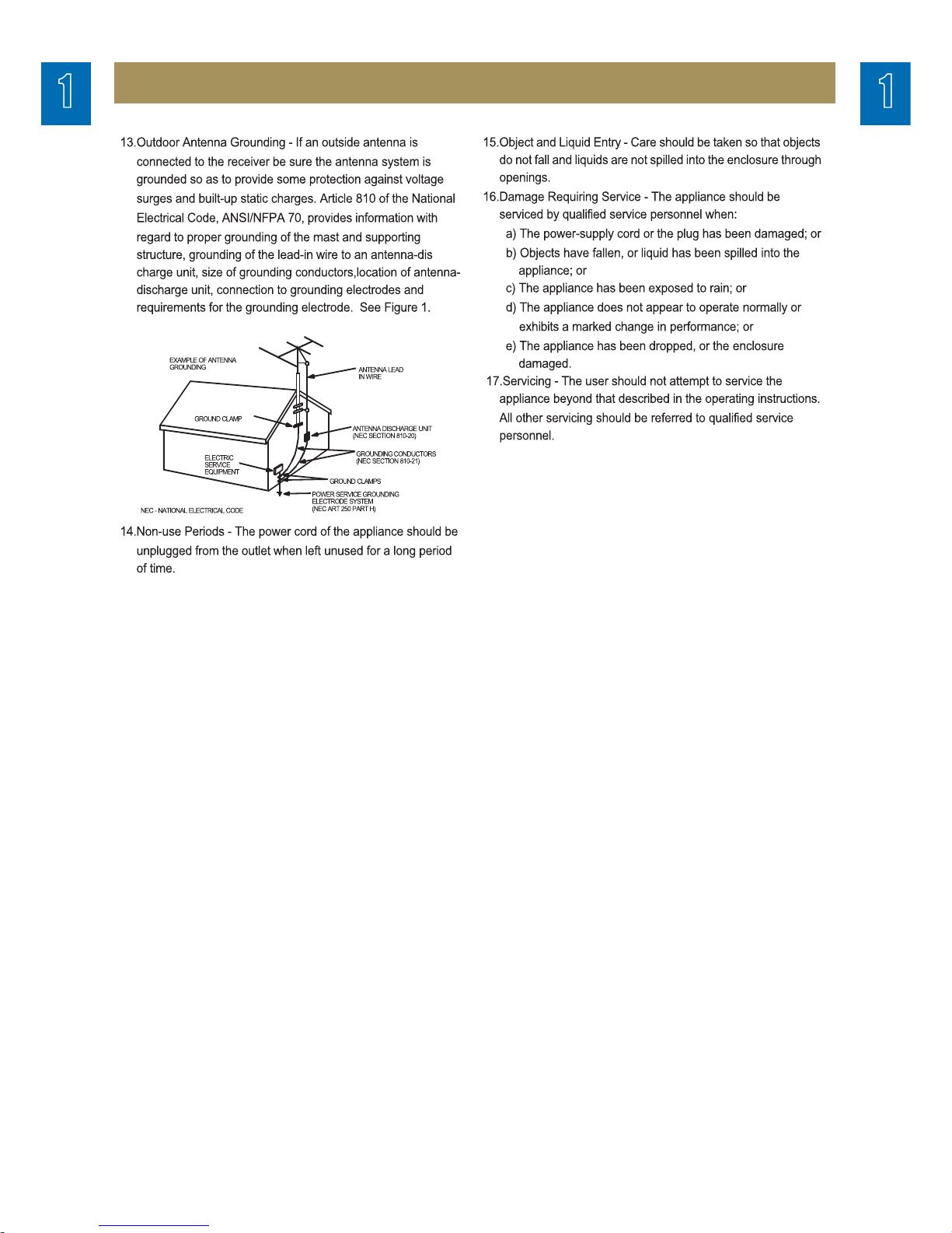
SAFETY PRECAUTIONS
.........................................................................................
1
TROUBLE SHOOTING GUIDE
................................................................................
2
EXPLODED VIEW AND MECHANICAL PARTS LIST
.............................................
3
WIRING DIAGRAM
...................................................................................................
4
BLOCK DIAGRAM
....................................................................................................
5
SCHEMATIC DIAGRAM
...........................................................................................
6
FRONT&TUNER Section
MP3/CD Section
P.C.B PATTERN LAYOUT
.........................................................................................
7
FRONT Section
MP3/CD Section
APPENDIX-ELECTRICAL PART LIST
...................................................................
8
Table of Contents
Mini component sound system
NC-8112E/NC-8114E/NC-8115E/NC-8117E
SMPS Section
TUNER Section
SMPS Section
MAIN Section
MAIN Section
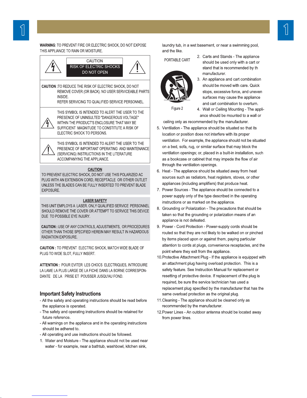
Safety Precautions
1
2
3
4
5
6
7
8
9
1
2
3
4
5
6
7
8
9
1
2
3
4
5
6
7
8
9
2
3
4
5
6
7
8
9
Safety Precautions
1
MP3/CD Section
4
5
6
7
8
9
1
2
3
4
5
6
7
8
9
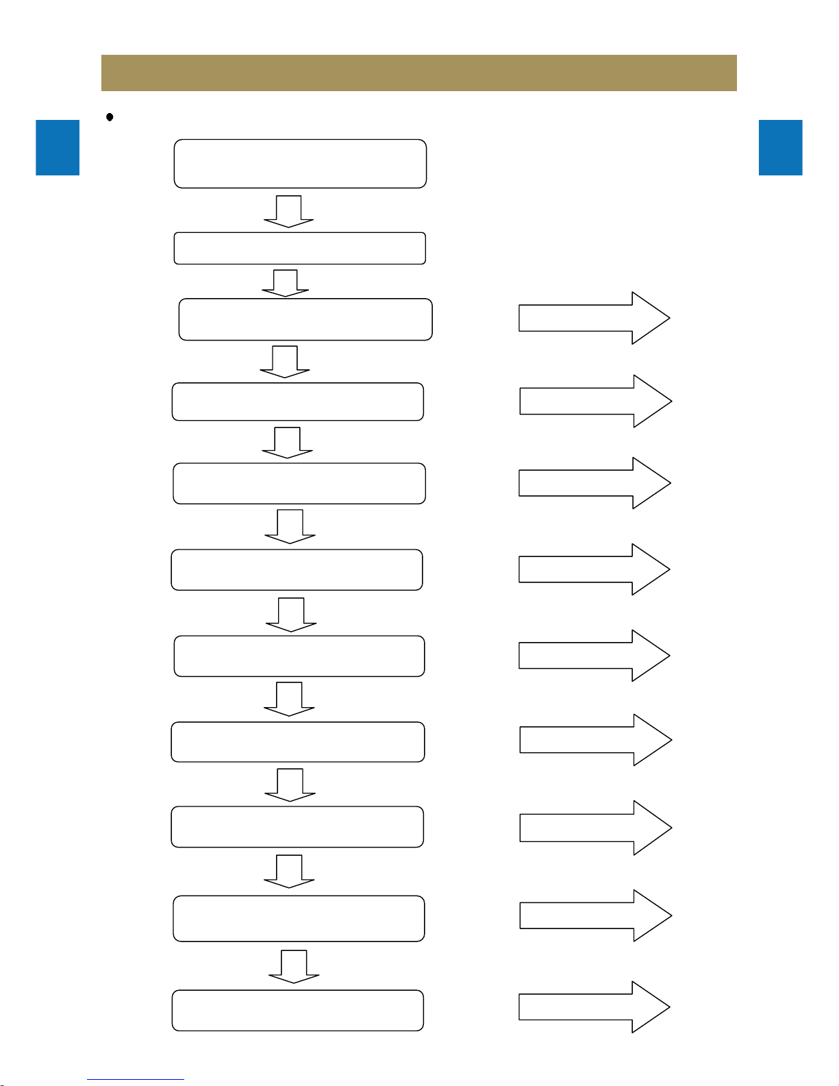
Trouble Shooting Guide
1
2
3
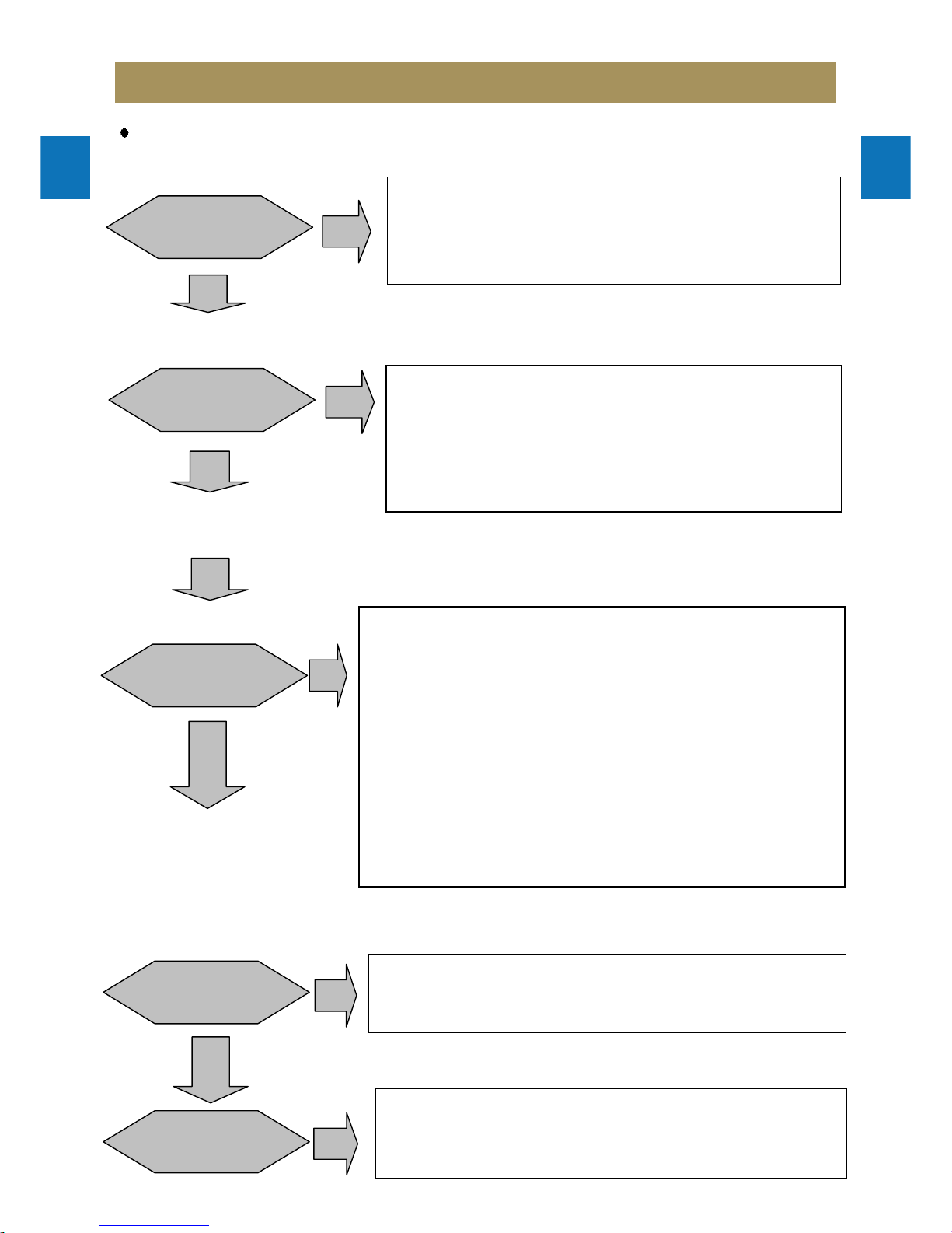
CD open and disc insert
Refer to 2
Spindle motor rotation
Pick-up unit return(outside >> inside)
and Rollette rotation
Laser diode on
Focusing operation
Read in CD/MP3 disc operation
Reading and auto play
CD play on
Refer to 3
Refer to 4
Refer to 5
Refer to 6
Auto to play
CD close and CD on
Refer to 1
AC cord in
Power ON/OFF ON
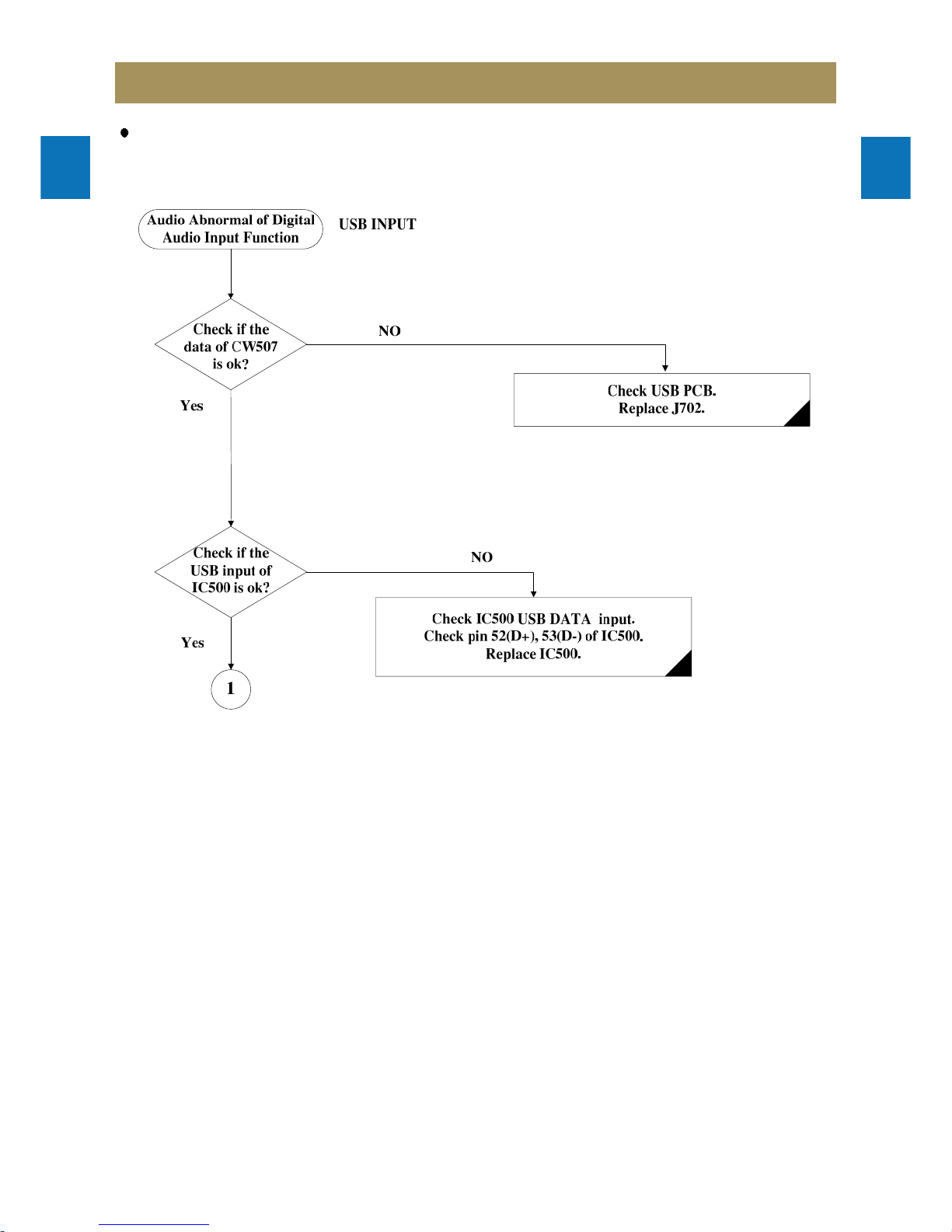
Reading in USB file and USB
Encoding operation
Refer to 7

MP3/CD Section
4
5
6
7
8
9
1
2
3
4
5
6
7
8
9
Trouble Shooting Guide
1
2
3
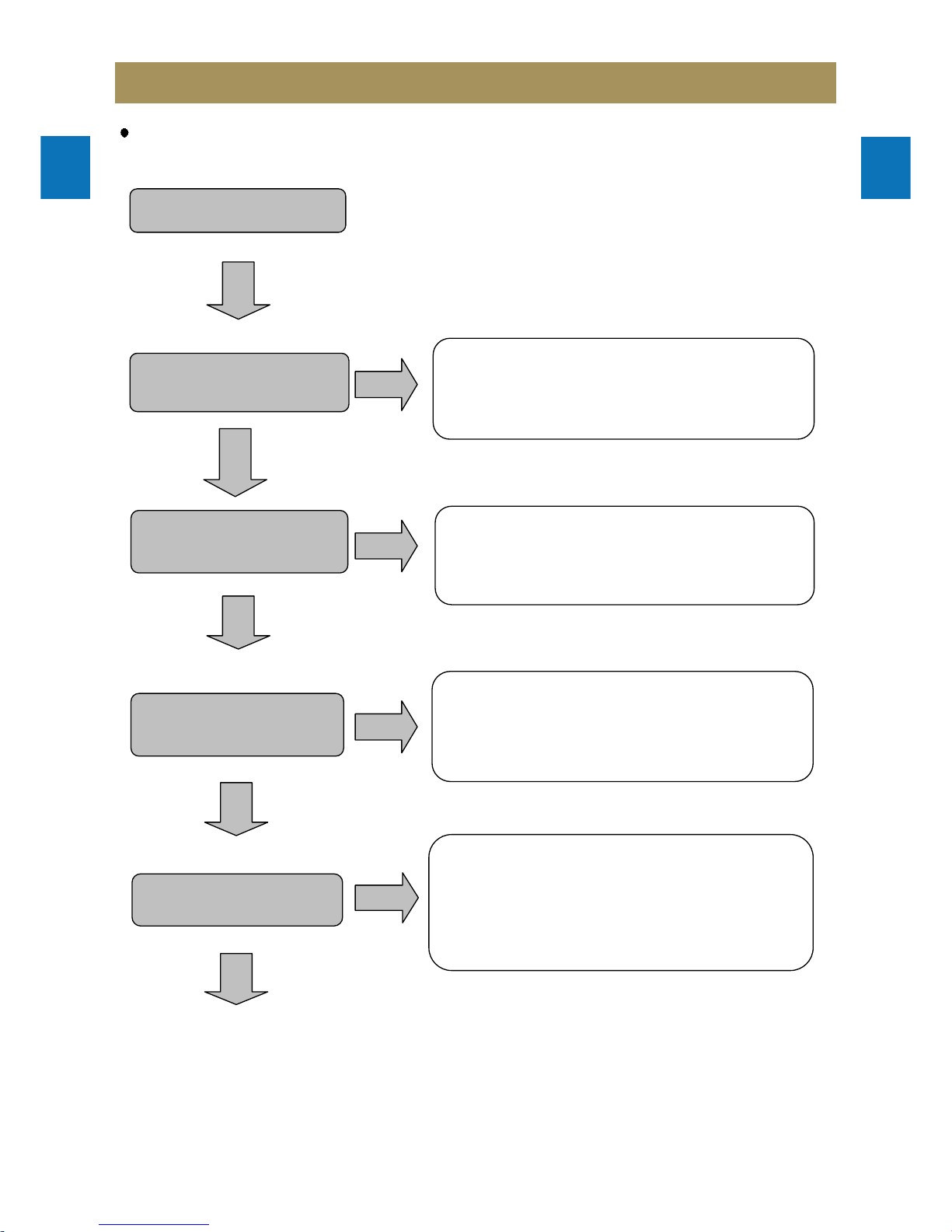
1. Pick-up unit return
2. CD o
p
en and disc insert
3. Laser diode on
STOP PLAY
C 0V 1.8V
B 3.3V 2.1V
(HQ500)
E 3.3V 2.8V
CD open and disc
insert
AC cord in
Function to CD
and Initializing CD
no
1.Check CN704
2.Check IC707(MCU IC) of 23/24/25/26/27/28pin
3.Check IC705 of 5/12/13pin
4. Check CN502,CW504.CN505
5. Check IC504 of 3pin:5.0V
6. Check Q501 collector:+3.3V
7. Check +3.3V (IC500 pin8/18/23/25/38/57/85
/113/116/122)
8. Check (IC502 SA5888 of 17pin and 18pin)SP+ 4.41V ,
SP- 3.41V
9. Check SPDO +1.90V (IC500 M5675 pin123)
10. Check (IC502 SA5888 of 12pin and 11pin) SL- 3.81V,
SL+ 3.91V
11. Check CD Board(Around IC solder short,cold soldering )
CD open and disc insert
Yes
Yes
CD close and cd on
Laser diode on
Yes
Focusing operation
no
1. Check +1.8V LD on(HQ500 collector)
2. Check +2.1V (HQ500 base pin) >>>in case of play
B
E
C
no
Yes
Yes
Power ON/OFF ON
no
1. Check CN505 of 5pin.
2. Check IC502 SA5888 of 10pin
no
1. Check CN505 of 3pin.
2. Check IC502 SA5888 of 9pin
1.Check CN700
2.Check IC701 of 33pin/40pin:3.3V
3..Check IC707(MCU IC) of 32pin:(main power on)
MP3/CD Section
4
5
6
7
8
9
1
2
3
4
5
6
7
8
9
Trouble Shooting Guide
1
2
3
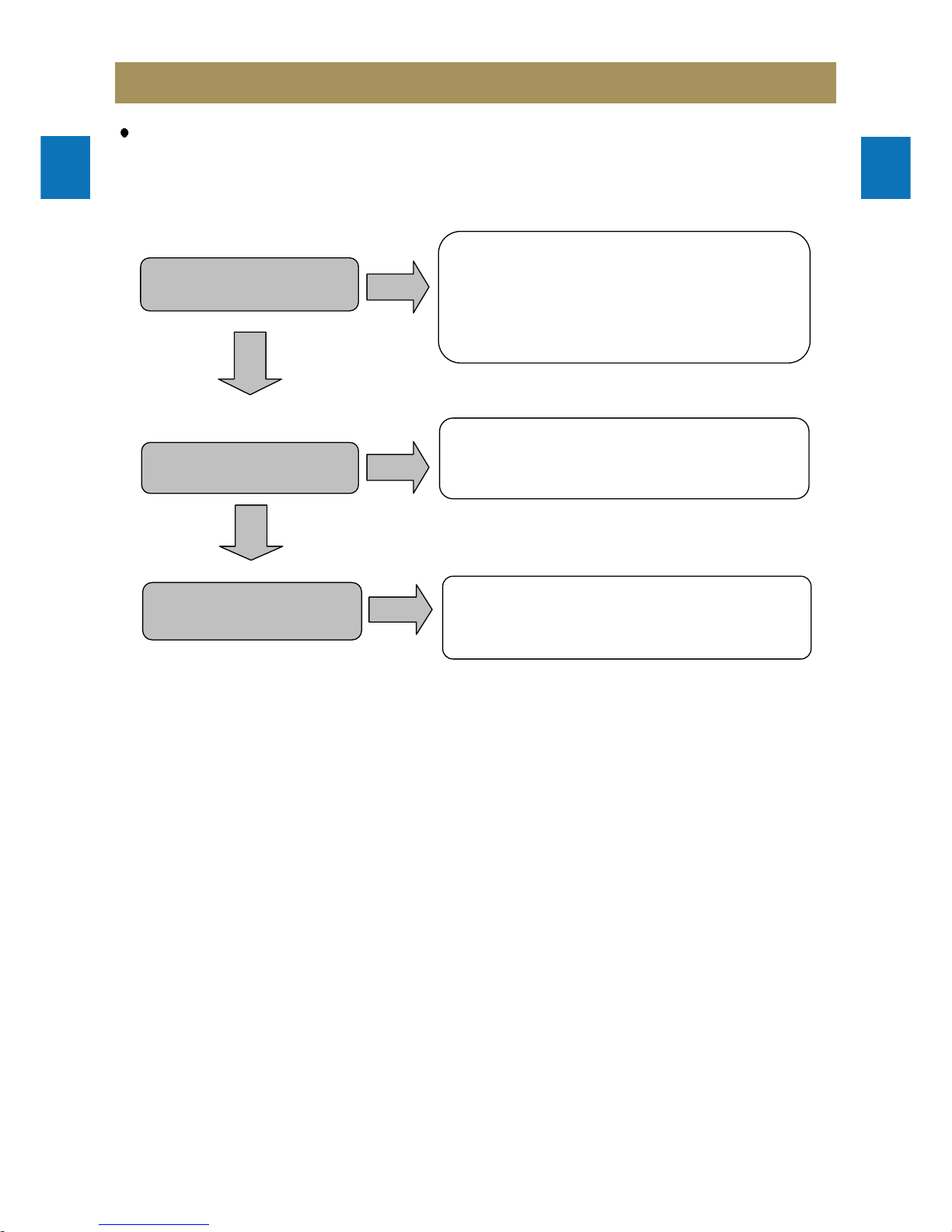
4. Focusing operation
5. Spindle motor rotation
6. Read in CD/MP3 disc operation
7. Read in USB file and USB Encoding operation
Focusing
operation
Yes
no
1. Check (IC502 SA5888 of 13pin and 14pin)
13pin 3.95V >>3.99V, pin18 3.72V >> 3.75V >>>
in case of play.
2. Check +1.58V(IC500 M5675 of 126pin).
Spindle motor
rotation
Yes
no
1. Check SPDO +1.90V(IC500 M5675 of 123Pin)
in case of play。
2. Check (IC502 SA5888 of 12pin and 11pin) SL- 3.81V,
SL+ 3.91V.
3. Check (IC502 SA5888 of 17pin and 18pin)SP+ 4.41V ,
SP- 3.41V
Read in CD/MP3
disc
Yes
no
Yes
1.Check CN704
2.Check IC707(MCU IC) of 23/24/25/26/27/28pin
3.Check IC705 of 5/12/13pin
4. Check CN502,CW504.CN505
5. Check IC504 of 3pin:5.0V
6. Check Q501 collector:+3.3V
7. Check +3.3V (IC500 pin8/18/23/25/38/57/85/113/116/122)
8. Check (IC502 SA5888 of 17pin and 18pin)SP+ 4.41V ,
SP- 3.41V
9. Check SPDO +1.90V (IC500 M5675 pin123)
10. Check (IC502 SA5888 of 12pin and 11pin) SL- 3.81V,
SL+ 3.91V
11. Check CD Board(Around IC solder short,cold soldering )
Yes
Read in USB file
operation
1. Check IC500(M5675) of 52pin and 53pin.
2. Check CW507,CN707.
3. Check J702.
no
USB Encoding
no
1. Check IC500 (M5675) of 52pin and 53pin.
2. Check CN502 7pin 8pin and 9pin.
3. Check IC500(M5675) 40pin,43pin input signal.
4. Check IC500(M5675) 33pin,36pin output signal.
Trouble Shooting Guide
1
2
3
4
5
6
7
8
9
1
Front & Tuner Section
2
3
4
5
6
7
8
9
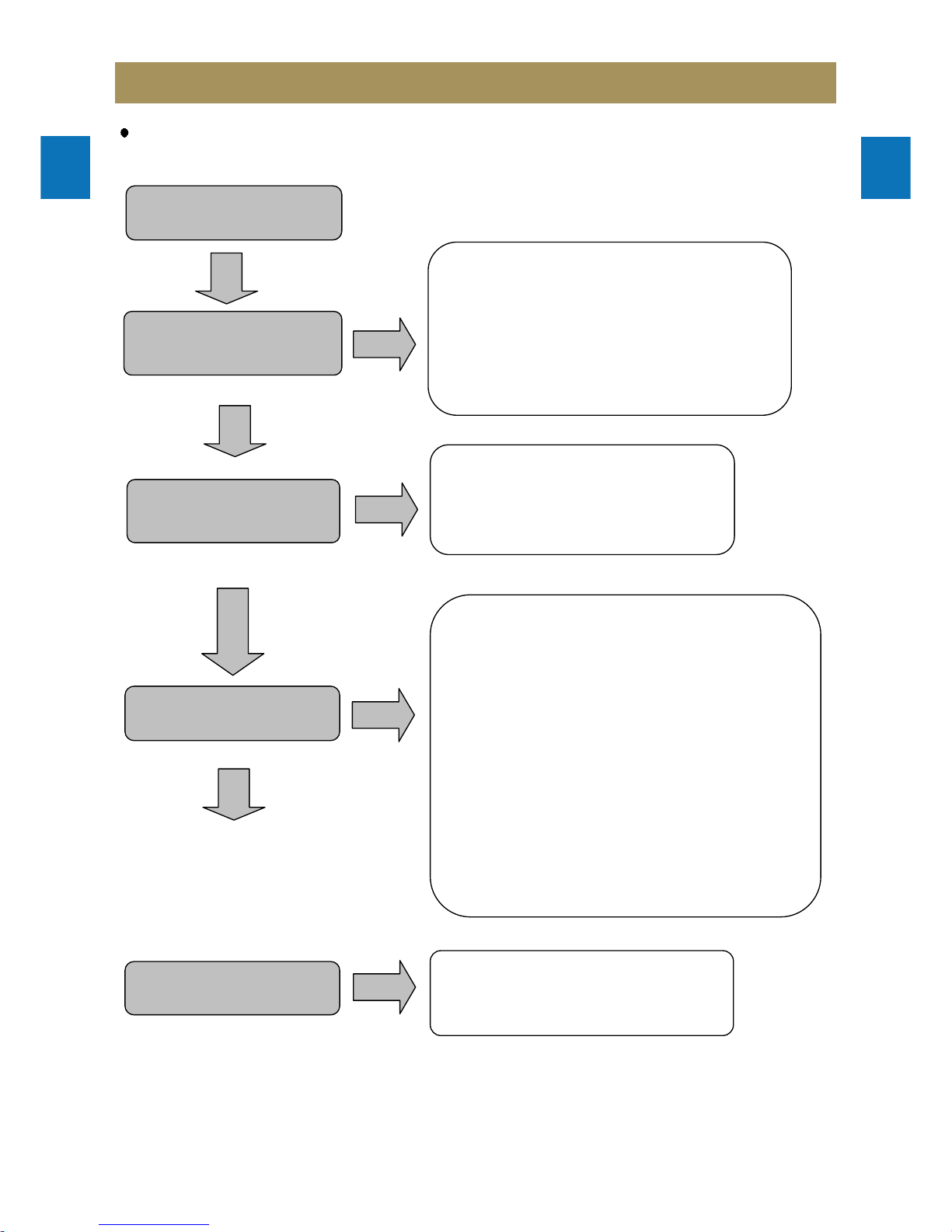
AC cord in
Yes
Power ON/OFF ON
Yes
Yes
no
no
VFD Display
Function command
no
Yes
1.Check IC707(MCU IC) of 44/45/46/47/48pin
2.Check SW701/SW702/SW703/SW704/
SW705/SW706/SW707/SW708/SW709/
SW710/SW711/SW712/SW713/SW714
SW715/SW716/SW717/SW718/SW719.
Function LED light
no
1.Check CN700 of 10pin:5V
2.Check LD705/LD706/LD707/LD709/
LD710/LD711/LD712/LD713/LD714/
LD715
Yes
1.Check CN700
2.Check IC701 of 33pin/40pin:3.3V
3.Check IC707(MCU IC) of 32pin:(main power on)
1.Check CN702
2.Check FD701(VFD)
3.Check IC701(SC16315)
Trouble Shooting Guide
1
2
3
4
5
6
7
8
9
1
Front & Tuner Section
2
3
4
5
6
7
8
9
Change to tuner function
no
1.Check IC707(MCU IC) of 27/28/31pin
2.Check CN703
3.Check CW703
4.Check IC105(TUNER IC)
5.Check X104(12MHZ)
Yes
Change to CD function
no
1.Check CN704
2.Check IC707(MCU IC) of 23/24/25/26/27/28pin
3.Check IC705 of 5/12/13pin
Yes
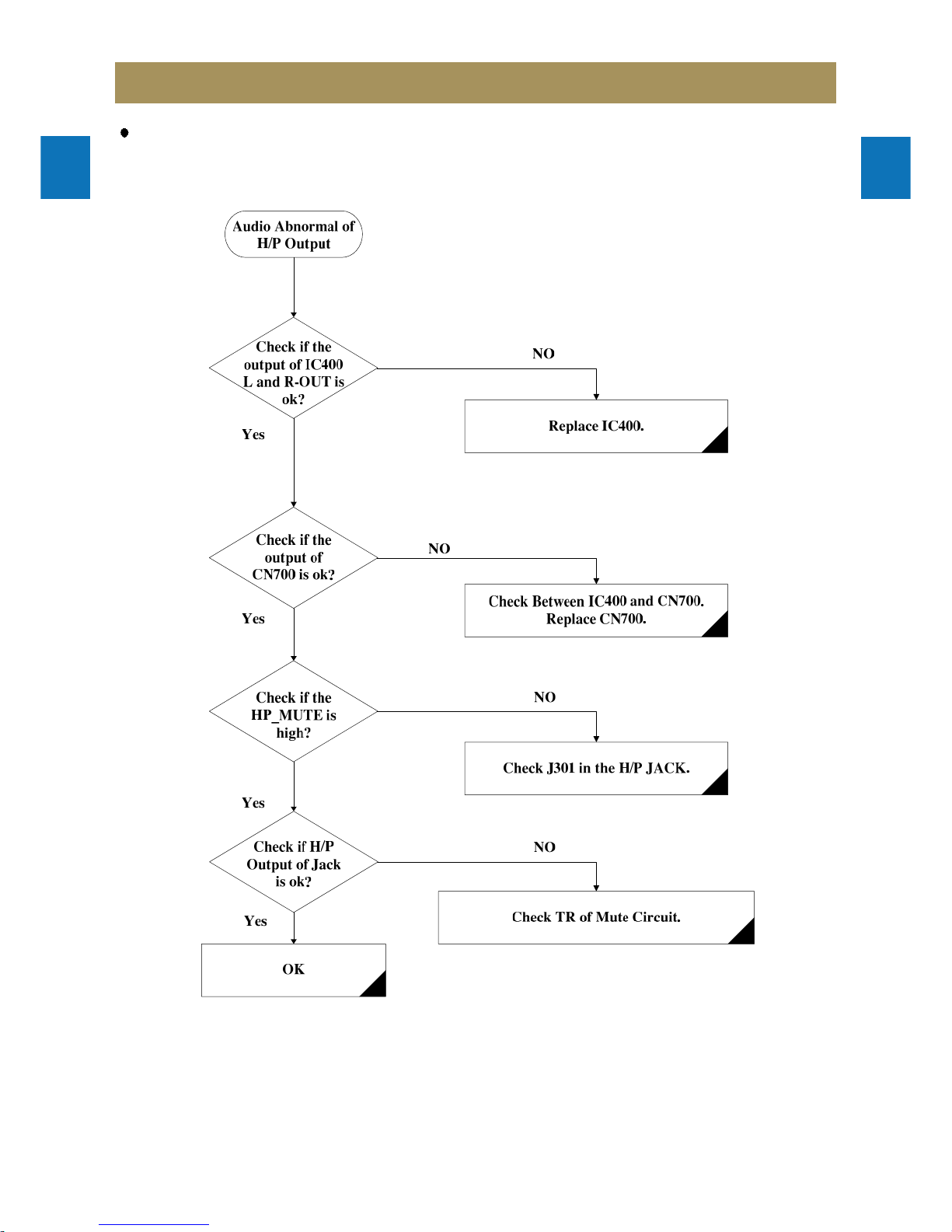
Phones sound
no
1.Check J301
2.Check IC702(IL4560D)
3.Check CN700
Trouble Shooting Guide
1
2
3
4
5
6
7
8
9
1
SMPS & AMP Section (Only NC-8112E Model)
2
3
4
5
6
7
8
9
AC cord in
no
Tuner/AUX/CD/USB Speaker
sound
no
Phones sound
no
Power ON/OFF ON
Yes
1.Check F901
2.Check PT901
3.Check CW902 of 6pin:3.3V
4.Check CW902 of 7pin:(main power on)
5.Check CN700
6.Check IC707(MCU IC)of 33pin/40pin:3.3V
7.Check IC707(MCU IC) of 32pin:(main power
on)
no
VFD Display
1.Check CW903
2.Check CN702
3.Check FD701(VFD)
4.Check IC701(SC16315)
1.Check J301
2.Check IC702(IL4560D)
3.Check CN700
Yes
Yes
1.Check CW901 of 1/2pin voltage:22V
2.Check CN801 of 1/2pin voltage:22V
3.Check IC800(TDA7492P): Voltage of 6/7pin
and 12/13pin :22V
4.Check IC800(TDA7492P):Voltage of 20pin and
21pin :3.3V
5.Check IC801(SA1117BH-3.3):Voltage of
2pin :3.3V
6.Check IC400(SC7314S):
Voltage of 1pin: normal DC(9V).
7.Check TUNER/AUX/CD input signal
8.Check output signal pin of IC800(TDA7492P)
2/3pin, 8/9pin and 10/11pin,16/17pin.
9.Check output signal terminals(J800).
Yes
Trouble Shooting Guide
1
2
3
4
5
6
7
8
9
1
SMPS & AMP Section (Only NC-8114E/NC-8115E Model)
2
3
4
5
6
7
8
9
AC cord in
no
Tuner/AUX/CD/USB Speaker
sound
no
Phones sound
no
Power ON/OFF ON
Yes
1.Check F901
2.Check PT901
3.Check CN902 of 6pin:3.3V
4.Check CN902 of 7pin:(main power on)
5.Check CN700
6.Check IC707(MCU IC)of 33pin/40pin:3.3V
7.Check IC707(MCU IC) of 32pin:(main power
no
VFD Display
1.Check CW903
2.Check CN702
3.Check FD701(VFD)
4.Check IC701(SC16315)
1.Check J301
2.Check IC702(IL4560D)
3.Check CN700
Yes
Yes
1.Check CN901 of 1/2/3pin voltage:33.5V
2.Check CW801 of 1/2/3pin voltage:33.5V
3.Check IC800(TDA7498): Voltage of 6/7pin
and 12/13pin :33.5V
4.Check IC800(TDA7498):Voltage of 20pin and
21pin :3.3V
5.Check IC801(SA1117BH-3.3):Voltage of
2pin :3.3V
6.Check IC400(SC7314S):
Voltage of 1pin: normal DC(9V).
7.Check TUNER/AUX/CD input signal
8.Check output signal pin of IC800(TDA7492P)
2/3pin, 8/9pin and 10/11pin,16/17pin.
9.Check output signal terminals(J800).
Yes
Trouble Shooting Guide
1
2
3
4
5
6
7
8
9
1
SMPS & AMP Section (Only NC-8117E Model)
2
3
4
5
6
7
8
9
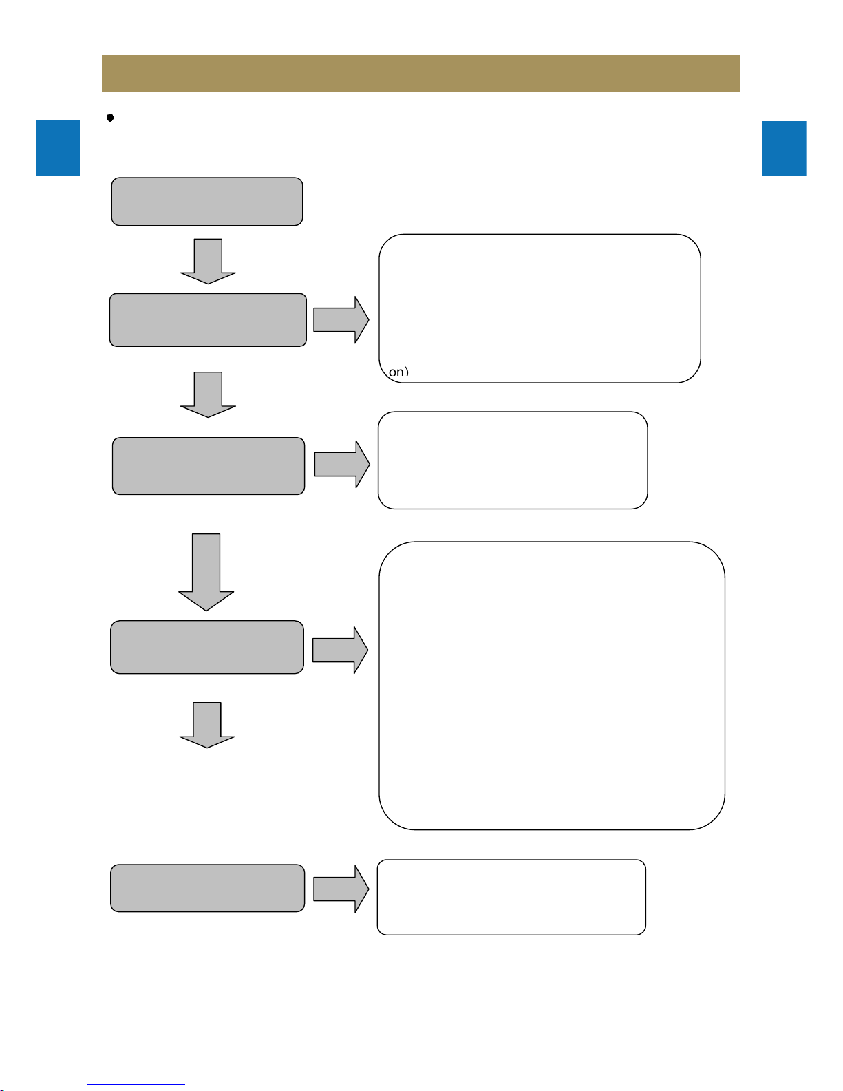
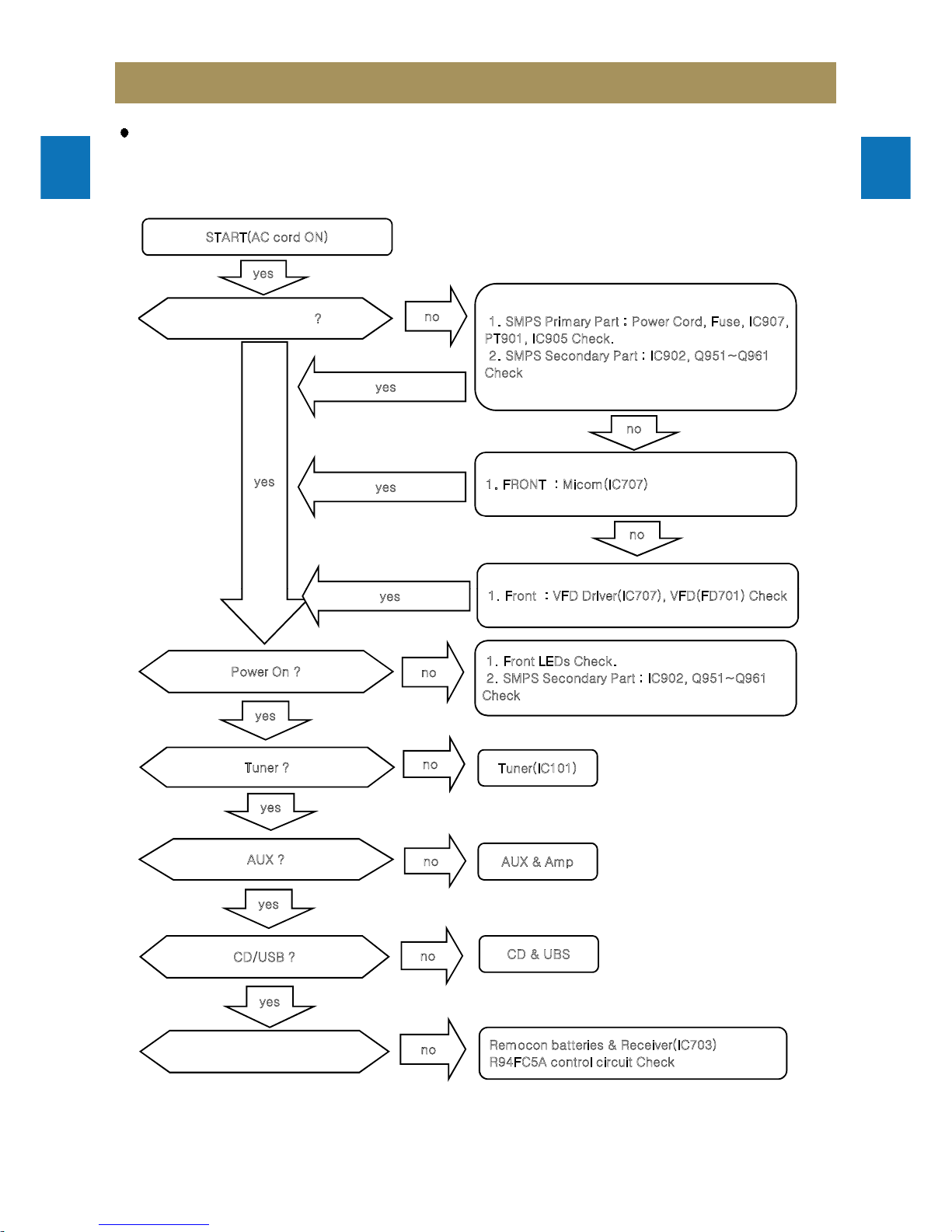
START(AC cord ON)
1. SMPS Primary Part : Power Cord, Fuse, IC907,
PT901, IC905 Check.
2. SMPS Secondary Part : IC902, Q951~Q961
Check
yes
no
DISPLAY(DEMO) ?
yes
1. FRONT : Micom(IC707)
yes
no
yes
no
CD/USB ?
no
Power On ?
no
yes
Tuner ?
no
AUX ?
no
yes
Tuner(IC101)
AUX & Amp
CD & UBS
no
Remocon ?
yes
yes
Remocon batteries & Receiver(IC703)
R94FC5A control circuit Check
1. Front : VFD Driver(IC707), VFD(FD701) Check
yes
1. Front LEDs Check.
2. SMPS Secondary Part : IC902, Q951~Q961
Check
Trouble Shooting Guide
1
2
3
4
5
6
7
8
9
1
SMPS & AMP section (Only NC-8117E Model)
2
3
4
5
6
7
8
9
Trouble Shooting Guide
1
2
3
4
5
6
7
8
9
1
SMPS & AMP section (Only NC-8117E Model)
2
3
4
5
6
7
8
9
Trouble Shooting Guide
1
2
3
4
5
6
7
8
9
1
SMPS & AMP section (Only NC-8117E Model)
2
3
4
5
6
7
8
9
Trouble Shooting Guide
1
2
3
4
5
6
7
8
9
1
SMPS & AMP section (Only NC-8117E Model)
2
3
4
5
6
7
8
9
Trouble Shooting Guide
1
2
3
4
5
6
7
8
9
1
SMPS & AMP section (Only NC-8117E Model)
2
3
4
5
6
7
8
9
Trouble Shooting Guide
1
2
3
4
5
6
7
8
9
1
SMPS & AMP section (Only NC-8117E Model)
2
3
4
5
6
7
8
9
 Loading...