


Service Manual
XGA COLOR MONITOR
Model : 902D
DAEWOO ELECTRONICS CO., LTD
OVERSEAS SERVICE DEPT.
CONTENTS
SAFETY PRECAUTIONS 1
GENERAL SAFETY INFORMATION 2
SERVICING PRECAUTIONS 3
TECHNICAL INFORMATION 6
GENERAL INFORMATION 7
PIN CONNECTOR 8
CAUTIONS FOR ADJUSTMENT AND REPAIR 8
OPERATION AND ADJUSTMENT 9
ALIGNMENT PROCEDURE 13
TROUBLESHOOTING HINTS 15
BLOCK DIAGRAM 31
PCB LAYOUT 32
SCHEMATIC DIAGRAM 36
EXPLODED VIEW & MECHANICAL PARTS LIST 39
INFORMATION OF PART DESCRIPTION 40
ELECTRICAL PARTS LIST 41
1
SAFETY PRECAUTIONS
◆ Safety Check
Care should be taken while servicing this analog color display because of the high voltages used in the deflection circuits.
These voltages are exposed in such areas as the associated flyback and yoke circuits.
◆ Fire & Shock Hazard
• Insert an isolation transformer between the analog color display and AC power line before servicing the
chassis.
• When servicing, pay close attention to the original lead dress especially in the high voltage circuit area; if a
short circuit is found, replace all parts which have been overheated as a result of the short circuit.
• All the protective devices must be reinstalled per original design.
• Soldering must be inspected for possible cold solder points, frayed leads, damaged insulation, solder splashes
or sharp solder points. Be certain to remove all foreign materials.
◆ Implosion Protection
Picture tube in this monitor employs intergral implosion protection system, but care should be taken to
avoid damage and scratching during installation.
Only use same type replacement picture tubes.
◆ X-Ray
IMPORTANT SAFETY NOTICE: There are special components used in this analog color display, which
are important for safety . These parts are shaded on the schematic
diagram and on the replacement parts list. It is essential that these
critical parts should be replaced with manufacturer’s specified parts to
prevent X-Ray , shock, fire or other hazards. Do not modify the original
design without getting written permission from DAEWOO
ELECTRONICS CO. or this will void the original parts and labor
warranty .
CAUTION: No modifications of any circuits should be attempted. Service work should be performed only
after you are thoroughly familiar with all of the following safety checks and servicing
guidelines.
WARNING: The only potential source of X-Ray is the picture tube. However when the high voltage
circuitry is operating properly, there is no possibility of an X-Ray problem. The basic
precaution which must be exercised is to keep the high voltage at the following factory
recommended level.
NOTE: It is important to use an accurate, periodically, calibrated high voltage meter.
• To measure the high voltage, use a high-impedance high-voltage meter.
Connect(-) to chassis and (+) to the CRT anode button.
• Turn the Contrast & Brightness Control fully counterclockwise.
• Measure the high voltage. The high voltage meter should indicate the following factory
recommended levels.
• If the upper meter indication exceeds the maximum level, immediate service is required to
prevent the possibility of premature component failure.
• To prevent X-Ray possibility, it is essential to use the specified picture tube.
• The normal high voltage is 25.5KV or below and must not exceed 29KV at zero beam current
at rated voltage.
2
Warning:This product includes critical mechanical and electrical parts which are essential for x ray
protection. For continued safety, replace critical components that are indicated in the service
manual with exact replacement parts given in the parts list.
Operating high voltage with this product is 29Kv at minimum brightness. Refer to service manual
for measurement procedures and proper service adjustments.
GENERAL SAFETY INFORMATION
◆ Terms in the manual
CAUTION Statements identify conditions or practices that could result in damage to the equipment or
other property.
WARNING Statements identify conditions or practices that could result in personal injury or loss of
life.
◆ Terms as marked on equipment
CAUTION Statements indicate a personal injury hazard not immediately accessible as one reads the
marking or a hazard which is properly included on the equipment itself.
WARNING Statements are clearly concerning indicated personal injury hazards.
◆ Symbols in the manual
The symbols indicate where applicable cautionary or other information is to be found.
◆ Symbols as marked on equipment
Protective GROUND terminal
◆ High Voltage Warning And Critical Component Warning Label
The following warning label is on the CRT PWB shield case inside the unit.
3
SERVICING PRECAUTIONS
◆ General Servicing Precautions
1. Always unplug the AC power cord from the AC power source before:
a. Removing or reinstalling any component, circuit board, module, or any other instrument assembly.
b. Disconnecting or reconnecting any electrical plug or other electrical connection.
c. Connecting a test substitute in parallel with an electrolytic capacitor in the instrument.
d. Discharging the picture tube anode.
2. Test high voltage only by measuring it with an appropriate high voltage meter or other voltage
measuring device (DVM, FETVOM. etc.) equipped with a suitable high voltage probe. Do not test high
voltage by “drawing an arc”.
3. Discharge the picture tube anode only by: (a) first connecting one end of an insulated clip lead to the
degaussing or line grounding system shield at the point where the picture tube socket ground lead is
connected, and then (b) touching the other end of the insulated clip lead to the picture tube anode
button, using an insulating handle to avoid personal contact with high voltage.
4. Do not any spray chemicals on or near this instrument, or any of its assemblies.
5. Unless otherwise specified in this service manual, only clean electrical contacts by applying the
following mixture to the contacts with a pipe cleaner, cotton-tipped stick, or comparable nonabrasive
applicator: 10% (by volume) Aceton and 90% (by volume) isopropyl alchohol (90%-99% strength).
6. Do not damage any plug/socket B+ voltage interlocks with which instruments covered by this service
manual might be equipped.
7. Do not apply AC power to this instrument and/or any other of its electrical assemblies unless all the
solid-state device heat sinks are correctly installed.
8. Always connect the test instrument ground lead to the appropriate instrument chassis ground before
connecting the test instrument positive lead. Always remove the test instrument ground lead last.
9. Only use the test fixtures specified in this service manual with this instrument.
CAUTION: Before servicing instruments covered by this service manual, its supplements, and addendum,
please read and follow the SAFETY PRECAUTIONS of this manual.
NOTE: If unforeseen circumstances create conflict between the following servicing precautions and any of
the safety precautions on page 1 of this manual, always follow the safety precautions.
Remember: Safety First.
CAUTION: A wrong part substitution or incorrect polarity installation of electrolytic capacitors
may result in a explosion.
CAUTION: This is a flammable mixture. Unless specified in this service manual, lubrication of contacts is not
required.
CAUTION: Do not connect the test fixture ground strap to any heatsink in this instrument.
4
◆ Electrostatically Sensitive (ES) Devices
Some semiconductor (solid state) devices can be damaged easily by static electricity.
Such components are commonly called Electrostatically Sensitive (ES) Devices.
The typical examples of ES devices are integrated circuits, some field-effect transistors, and
semiconductor “chip” components. The following techniques should be used to help reduce the incidence
of component damage caused by static electricity.
1. Immediately before handling any semiconductor component or semiconductor-equipped assembly,
wipe off any electrostatic charge on your body by touching any known earth ground. Alternatively,
obtain and wear a commercially available discharging wrist strap device which should be removed for
potential shock reasons prior to applying power to the unit under testing conditions.
2. After removing the electrical assembly equipped with ES devices, place the assembly on a conductive
surface such as aluminum foil to prevent electrostatic charge buildup or exposure to the assembly.
3. Only use a grounded-tip soldering iron to solder or unsolder ES devices.
4. Only use an anti-static type solder removal device. Some solder removal devices not classified as “antistatic” can generate enough electrical charges to damage ES devices.
5.
Do not use freon-propelled chemicals. These can generate enough electrical charges to damage ES devices.
6. Do not remove a replacement ES device from its protective package until immediately before you are
ready to install it. (Most replacement ES devices are packaged with leads electrically shorted together
by conductive foam, aluminum foil, or comparable conductive material).
7. Immediately before removing the protective material from the leads of replacement ES devices, touch
the protective material to the chassis or circuit assembly into which the device will be installed.
8. Minimize bodily movements when handling unpackaged replacement ES devices. (Otherwise harmful
motion such as the brushing together clothes fabric or the lifting your foot from a carpeted floor can
generate enough static electricity to damage ES devices).
◆ General Soldering Guidelines
1. Use a grounded-tip, low-wattage soldering iron with appropriate tip size and shape that will maintain
tip temperature between a 550°F-660°F (288°C-316°C) range.
2. Use an appropriate gauge of RMA resin-core solder composed of 60 parts tin/40 parts lead.
3. Keep the soldering iron tip clean.
4. Throughly clean the surface to be soldered. Use a small wire-bristle (0.5 inch or 1.25cm) brush with a
metal handle. Do not use freon-propelled spray-on cleaners.
5. Use the following soldering technique:
a. Allow the soldering iron tip to reach normal temperature (550°F to 660°F or 288°C to 316°C)
b. Hold the soldering iron tip and solder strand against the component lead until the solder melts.
c. Quickly move the soldering iron tip to the junction of the component lead and the printed circuit foil,
and hold it there until the solder flows onto and around both the component lead and the foil.
d.
Closely inspect the solder area and remove any excess or splashed solder with a small wire-bristle brush.
CAUTION:
Be sure that no power is applied to the chassis or circuit, and observe all other safety
precautions.
CAUTION: Work quickly to avoid overheating the circuit board printed foil.
5
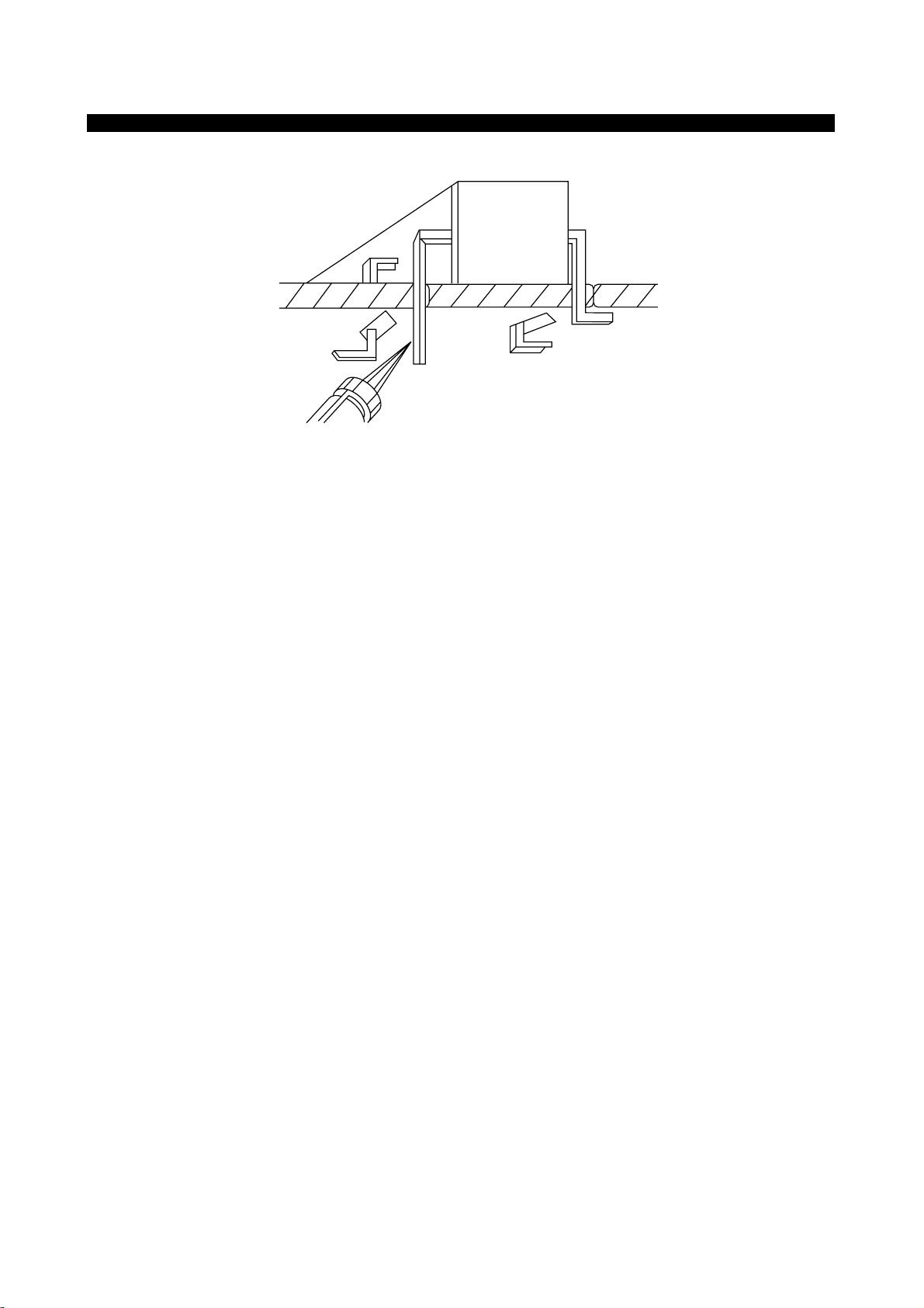
FIGURE 1. USE SOLDERING IRON TO PRY LEADS
◆ IC Removal/Replacement
Some utilized chassis circuit boards have slotted (oblong) holes through which the IC leads are inserted
and then bent flat against the circuit foil. When holes are slotted, the following technique should be used
to remove and replace the IC. When working with boards using the familiar round hole, use the standard
technique as outlined in paragraphs 5 on the page under the title of general soldering guidelines.
◆ Removal
1. Desolder and straighten each IC lead in one operation by gently prying up on the lead with the
soldering iron tip as the solder melts.
2. Draw away the melted solder with an anti-static suction-type solder removal device (or with
desoldering braid before removing the IC.
◆ Replacement
1. Carefully insert the replacement IC in the circuit board.
2. Carefully bend each IC lead against the circuit foil pad and solder it.
3. Clean the soldered areas with a small wire-bristle brush. (lt is not necessary to reapply acrylic coating
to the area).
◆ “Small-Signal” Discrete Transistor Removal/Replacement
1. Remove the defective transistor by clipping its leads as close as possible to the component body.
2. Bend the ends of each of three leads remaining on the circuit board into a “U” shape.
3. Bend the replacement transistor leads into a “U” shape.
4. Connect the replacement transistor leads to the corresponding leads extending from the circuit board
and crimp the “U” with long nose pliers to ensure metal-to-metal contact, then solder each connection.
6
◆ Power IC, Transistor or Devices Removal/Replacement
1. Heat and remove all solders from the device leads.
2. Remove the heatsink mounting screw (if applicable).
3. Carefully remove the device from the circuit board.
4. Insert new device in circuit board.
5. Solder each device lead and then clip off excess lead.
6. Replace heatsink.
◆ Diode Removal/Replacement
1. Remove defective diode by clipping its leads as close as possible to diode body.
2. Bend the two remaining leads perpendicularly to the circuit board.
3. Observing diode polarity, wrap each lead out of the new diode around the corresponding lead on the
circuit board.
4. Securely crimp each connection and solder it.
5. Inspect the solder joints of the two “original” leads on the circuit board copper side. If they are not
shiny, reheat them and apply additional solder if necessary.
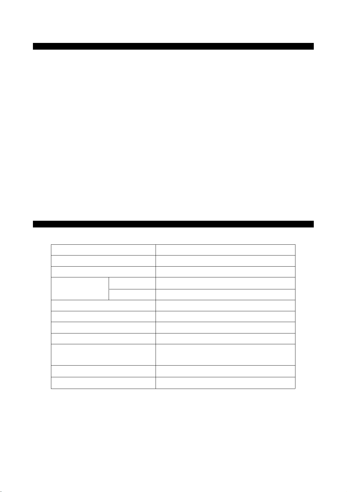
TECHNICAL INFORMATION
CDT Size 19-inch
Diagonal visible image area 18-inch
Dot Pitch 0.26 mm
Synchronization Horizontal 30 - 95 KHz
Vertical 50 - 160 Hz
Plug and Play DDC1/2B/CI
Power Saving EPA, VESA DPMS, Nutek Compliant
Power Source 100-240 Vac, 50/60Hz (Free Voltage)
Power Consumption 120 W
Dimension-W x H x D 466 x 475.5 x 464.5mm
(set with stand)
Weight-unpacked(lbs/Kg) 51.8/23.5
Operating Temperature 10 ~ 40°C /50 ~ 104°F
ADJ Adjustment
AFC Automatic Frequency Control
CRT Cathode Ray Tube
Def Deflection
D.Y Deflection Yoke
FBT Flyback Transformer
H.SYNC Horizontal Synchronization
OSC Oscillator
P.S.U Power Supply Unit
PWA Printed Circuit Board Wiring Assembly
R.G.B Red, Green, Blue
V.Sync Vertical Synchronization
7
GENERAL INFORMATION
This color monitor automatically scans all horizontal frequencies from 30KHz to 95KHz, and all vertical
frequencies from 50Hz to 160Hz. This color monitor supports IBM PC, PC/XT, PC/AT, personal
System/2 (PS/2), Apple Macintosh, and compatible users crisp text and vivid color graphics display when
using the following graphics adapters : (VGA, 8514/A, Super VGA, VESA and XGA and Apple
Macintosh Video Card). And so, this color monitor has a maximum horizontal resolution of 1600 dots and
a maximum vertical resolution of 1200 lines for superior clarity of display.
By accepting analog signal inputs which level is zero to 0.7 Volts. This color monitor can display and
unlimited palette of colors depending on the graphics adapter and software being used.
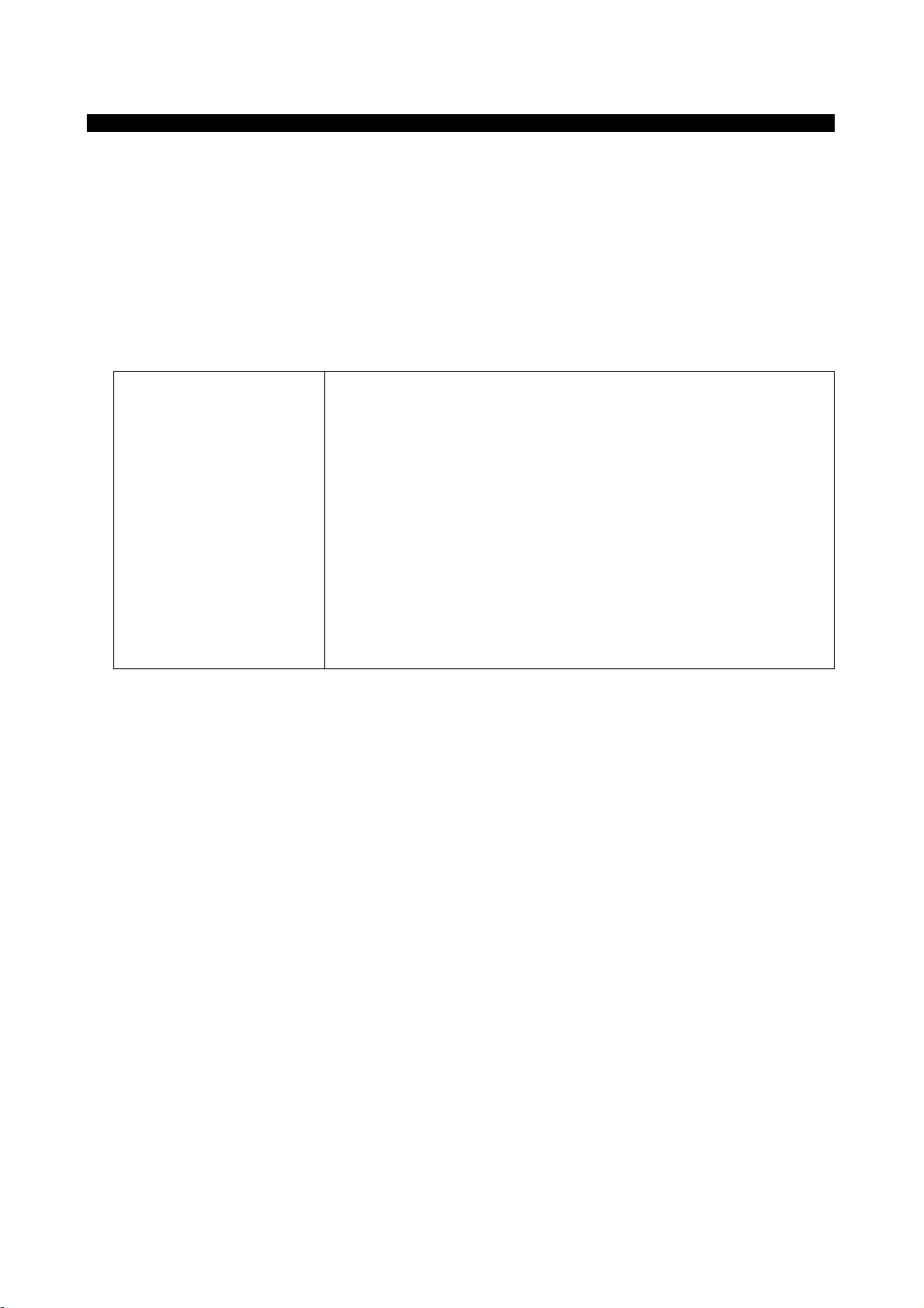
◆ Abbreviations
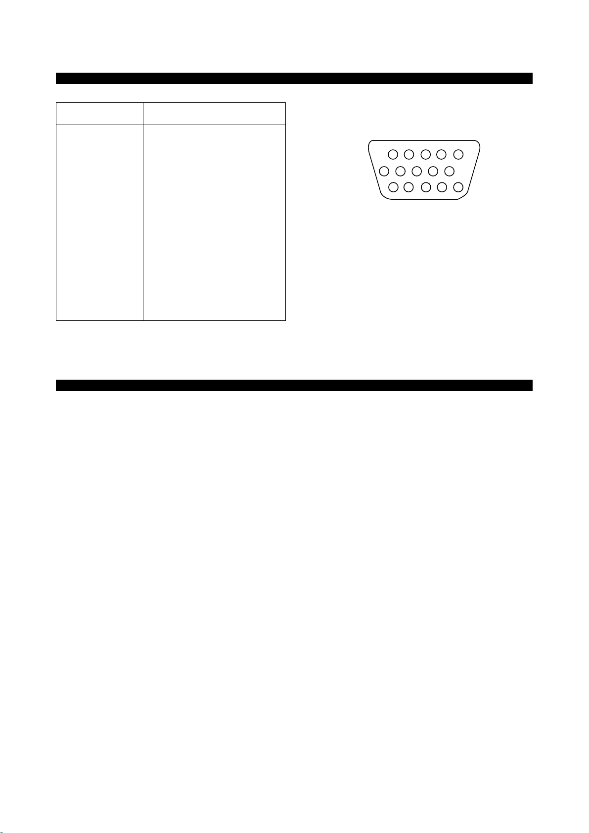
Pin Signal
1 Red
2 Green
3 Blue
4 GND
5 GND
6 GND - Red
7 GND - Green
8 GND - Blue
9 +5Vdc
10 GND - H.Sync
11 GND - V.Sync
12 Bi-directional Data (SDA)
13 Horizontal Sync
14 Vertical Sync (VCLK)
15 Data Clock (SCL)
8
• Degaussing is always required when adjusting purity or convergence.
• The white balance adjustment has been done by a color analyzer in factroy. The adjustment procedure,
described in the service manual is made by a visual check.
• Allow 20 minutes warm-up time for the display before checking or adjusting only electrical
specification or function.
• Reform the leadwire after any repair work.
◆ Caution For Servicing
• In case of servicing or replacing CR T, high voltage sometimes remains in the anode of the CRT. Completely discharge
high voltage before servicing or replacing CRT to prevent a shock to the serviceman.
Arrangement of 15-pin D-sub connector
PIN CONNECTOR
CAUTIONS FOR ADJUSTMENT AND REP AIR
1
6
15
10
9
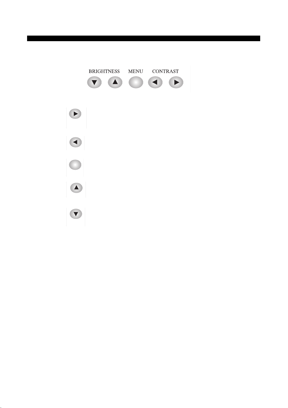
OPERATION AND ADJUSTMENT
Control Panel
• Move cursor to the right window on the OSD window.
• Increase the value of any selected function.
• Move cursor to the left window on the OSD window.
• Decrease the value of any selected function.
• Launch OSD(On-Screen Display) MENU window.
• Move cursor to the high window on the OSD window.
• Increase the value of V.size or V.center.
• Move cursor to the low window on the OSD window.
• Decrease the value of V.size or V.center.
10
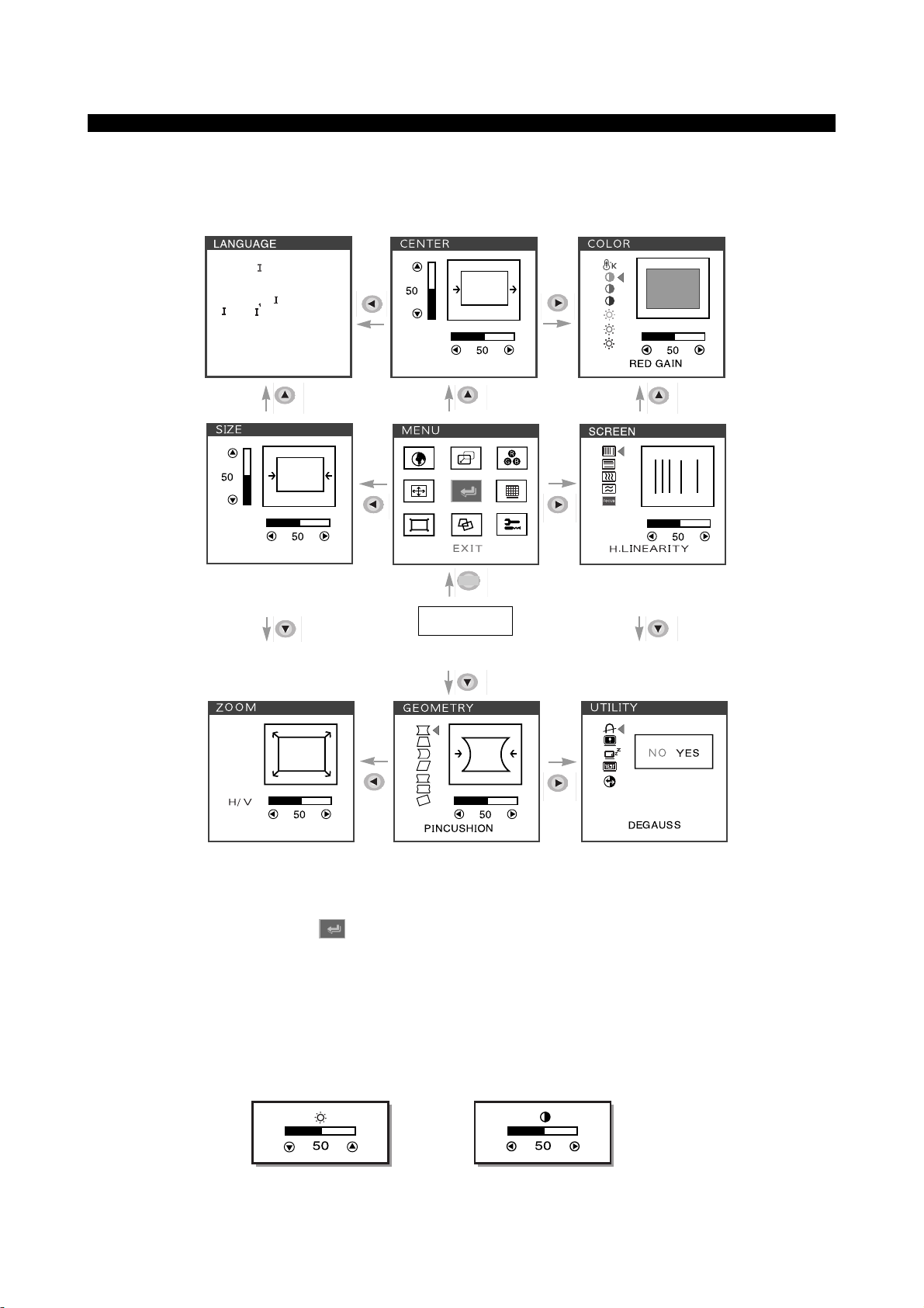
Key Process
•
When you choose the icon on the OSD window, you can exit the OSD screen.
Hot Key
BRIGHTNESS CONTRAST
DEUTSCH
ENGL SH
ESPAÑOL
FRANCA S
TAL ANO
Start
MENU
11
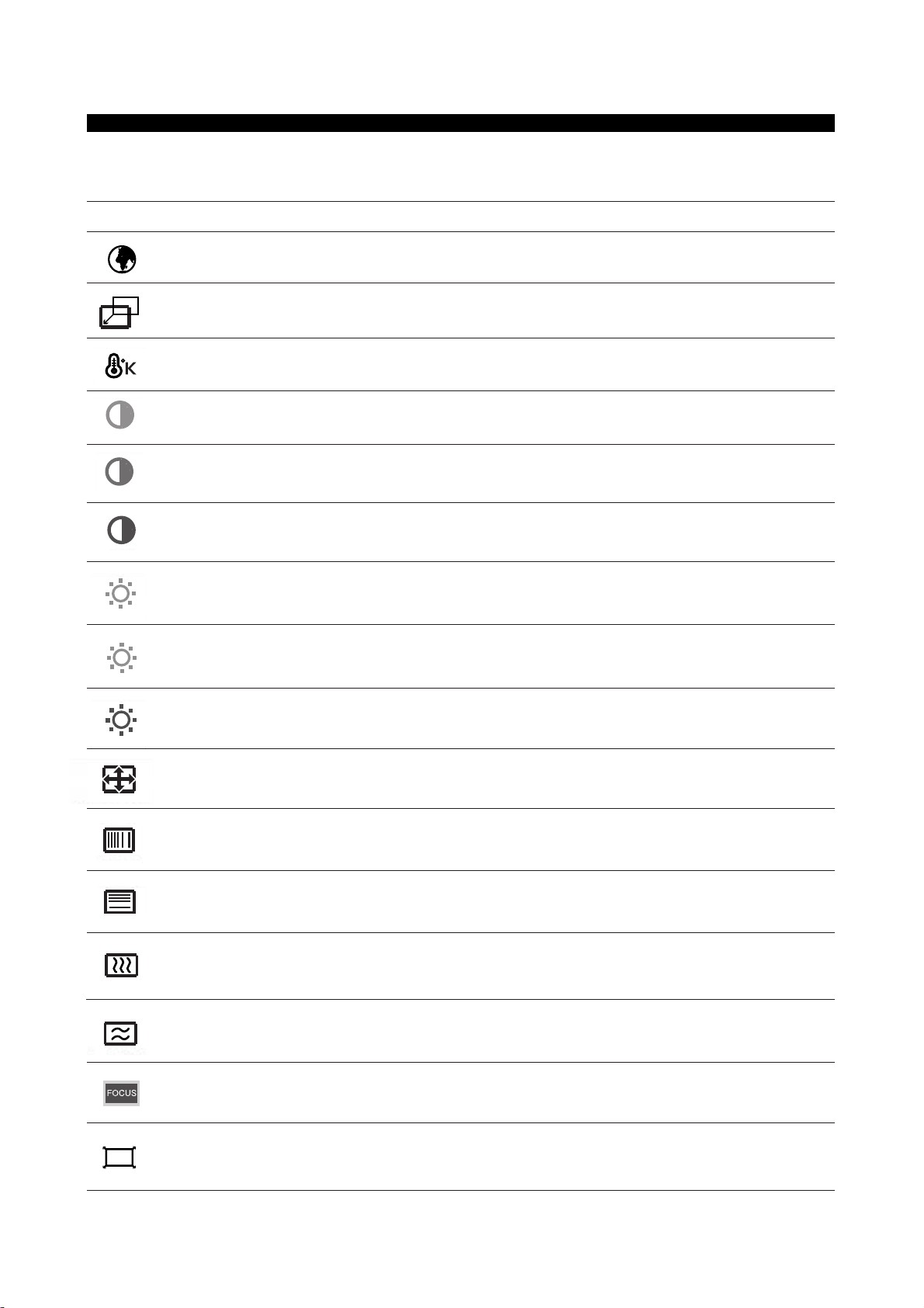
Adjust the width (horizontal size) and the height (vertical size) of the display.
H. SIZE &
V. SIZE
H. LINEARITY
V. LINEARITY
Adjust the horizontal linearity.
Adjust the vertical linearity.
Select language for OSD (5 languages).
LANGUAGE
Adjust the position of the display horizontally(left or right) and vertically (up or down).
H. CENTER &
V. CENTER
Choose different preset color temperatures or set your own customized color parameters.
Adjust the red gain.
Adjust the green gain.
Adjust the blue gain.
COLOR TEMP
RED GAIN
GREEN GAIN
BLUE GAIN
Adjust the red bias.
Adjust the green bias.
Adjust the blue bias.
RED BIAS
GREEN BIAS
BLUE BIAS
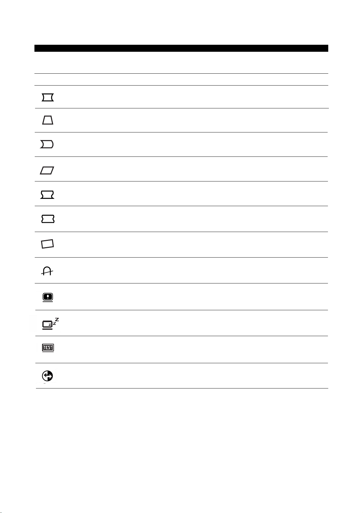
ICON CONTROL FUNCTIONS
OSD Functions
Adjust the vertical picture moire cancellation.
V. MOIRE
Adjust the focus image.
FOCUS
ZOOM
Adjust the display width & height at the same time.
Adjust the horizontal picture moire cancellation.
H. MOIRE
12
Adjust the parallelogram when the screen is leaning left or right.
Adjust the rotation when the screen is tilted left or right.
Adjust the pin S control when the sides of the screen are in a S shape.
ROTATION
PIN S Control
PARALLELOGRAM
Adjust the trapezoid of the screen by moving the lines inward or outward.
Adjust the side balance when the sides of the screen are bowed towards left or right.
PIN BALANCE
TRAPEZOID
Adjust the pin W control when the sides of the screen are in a W shape.
PIN W Control
Degauss the display and restore image quality.
DEGAUSS
Reset the screen to the Factory Preset Display Settings.
Display a RGB Color Bar to determine whether the screen color is expressed normally
or not.
TEST PATTERN
RECALL
Display horizontal & vertical frequency and polarity.
STATUS
POWER SAVER
YES : VESA DPMS operation.
NO : NO DPMS operation.
ICON CONTROL FUNCTIONS
Adjust the left and right margins for more convex or more concave margins.
PINCUSHION

13
◆
Standard Adjustment Conditions
1. Power source voltage : AC 100 - 240Vac, 50/60Hz.
2. Aging : Take at least 15 minutes warm-up time.
3. Signals.
Video : Analog 0.7Vpp 75W terminal positive polarity
Synchronizing : H+V Sync on Green : 0.286Vpp ± 5% (Negative)
Composite H+V Sync : 1.0Vpp ~ 5.0Vpp (Positive / Negative)
Separate H, V Sync : TTL Level (Positive / Negative)
Deflection frequency
Horizontal Frequency : 30KHz - 95KHz
Vertical Frequency : 50Hz - 160Hz
◆ Pre-Adjustment
1. B+ Adjustment
Adjust VR151 for 118Vdc between P6 and ground at 91KHz mode.
◆ Main Adjustment
1. Setting the Controls
Set contrast and brightness in Control Menu unless otherwise specified.
Contrast : Max.
Brightness : Center
2. H.size, H.phase, V.size, H.phase, Side Pincushion, Pincushion S, Pincushion W, Trapezoid,
Parallelogram, Rotation, Pin Balance, H.Linearity, V.Linearity
Receive the cross hatch pattern of Factory preset mode.
H.size, H.phase, V.size, H.phase, Side Pincushion, Pincushion S, Pincushion W, Trapezoid,
Parallelogram, Rotation, Pin Balance, H.Linearity, V.Linearity controls are adjusted at each mode.
In Factory, Auto Alignment was done at each mode. Therefore, Factory preset mode have their own
value according to each control.
3. Focus
(a) Set brightness control to center and contrast control to Maximum.
(b) Receive all “H” character pattern of 91KHz mode signal.
(c) Adjust the Static Focus VR to obtain best H.Focus.
(d) Adjust the Dynamic Focus VR to obtain best V.Focus.
(e) If the H/V Focus is not satisfactory, readjust the Static / Dynamic Focus.
4. White Balance Adjustment
(a) Select 9300°K on the OSD Menu.
(b) Receive a full white pattern of 91KHz mode signal by using the signal generator.
(c) Set the brightness control to maximum and the contrast control to maximum.
(d) Cut off the FBT screen VR.
(e) Receive all the black patterns. The luminance of the screen should be 0.5~0.7 Ft-L by using Screen
VR.
(f) Select the R-BIAS, G-BIAS and B-BIAS on the control menu and adjust the / key to get the
color coordinates in x=0.281 ± 0.015, y=0.311± 0.015.
(g) Receive a full white pattern. Adjust the brightness value to the center.
(h) Select the R-GAIN and B-GAIN and adjust the / key to get the color coordinates in x=0.281 ±
0.015, y=0.311 ± 0.015.
(i) Adjust the sub contrast control to get the screen luminance to 30 Ft/L (a full white pattern over 30
Ft/L)
(j) Check if the x, y coordinates of color analyzer is in x=0.281±0.015, y=0.311±0.015.
ALIGNMENT PROCEDURE

14
If the color coordinates is out of range, adjust the R. G. B BIAS & GAIN to get the coorinates in
x=0.281, y=0.311. Make sure that the coordinates is in the appropriate range.
(k) Select 6550°K on the OSD Menu and set the color coordinates in x=0.313, y=0.329 at the
maximum contrast control and center brightness control
(l) Check if a full white pattern is over 30Ft/L.
5. Static Convergence Adjustment
(a) Apply a magenta cross hatch pattern on display.
(b) Adjust the focus from the best over all focus on the display.
Also adjust the brightness to the desired condition.
(c) Vertical red and blue lines are converged by varying the angles between the two tabs of the 4-pole
magnets.
(d) Horizontal red and blue lines are converged by varying the tabs together and keeping the angle
between them constant.
(e) Apply a yellow cross hatch pattern on the display.
(f) Vertical green and red lines are converged by barying the angle between the two tabs of the 6-pole
magnets.
(g) Horizontal green and red lines are converged by varying the tabs together and keeping the angle
between them constant.
 Loading...