

Service
Service
Micro System
Service Manual
Service
Service
Service
MCM240/21/21M/22/25/37
TABLE OF CONTENTS
Page
Location of pc boards & Version variations................1-2
Technical Specifications .............................................1-3
Measurement setup ....................................................1-4
Service Aids, Safety Instruction, etc................ 1-5 to 1-6
Lead-free Information & Service Instruction ..............1-7
Preparations & Controls & Troubleshooting.. 1-8 to 1-10
Disassembly Instructions & Service positions .............. 2
Service Test Programs ............................................... 3-1
Set Block diagram ...................................................... 4-1
Set Wiring diagram .....................................................5-1
Power Board .................................................................. 6
Key Board ...................................................................... 7
Main Board .................................................................... 8
Set Mechanical Exploded view & parts list ................... 9
COMPACT
DIGITAL AUDIO
CLASS 1
©
Copyright 2005 Philips Consumer Electronics B.V. Eindhoven, The Netherlands
All rights reserved. No part of this publication may be reproduced, stored in a retrieval system or
transmitted, in any form or by any means, electronic, mechanical, photocopying, or otherwise
without the prior permission of Philips.
Published by SL 0529 Service Audio Printed in The Netherlands Subject to modification
Version 1.0
LASER PRODUCT
GB
3141 785 30330
LOCATION OF PRINTED CIRCUIT BOARDS
D
AR
1-2
HEADPHONE BOARD
OP/CL BO
MAIN BOARD
KEY BOARD
ANTENNA BOARD
VOL BOARD
SPEAKER BOARD
POWER BOARD
VERSION VARIATIONS:
Type /Versions: MC240
/21
Features &
Board in used:
Aux in / CDR in x x x x x
Line Out
Video Out
Surround Out
Subwoofer Out
Power Booster Out
Digital Out
Digital in
Matrix Surround
RDS x x
News x x
Dolby Pro Logic (DPL)
Incredible Surround
Karaoke Features
Voltage Selector x
ECO Power Standby (LCD Display Off) x x
ECO6 Tuner Board - Systems Non-Cenelec x x
ECO6 Tuner Board - Systems Cenelec x x
USB PC LINK
/21M /22 /25 /37
x
x

SPECIFICATIONS
GENERAL:
Mains voltage : 120/240V ± 15% Switchable for /21
120V ± 10% for /37
230V ± 10% for /22/25
240V ± 10% for /30
Mains frequency : 50/60Hz
Clock accuracy : < 4 seconds per day
Dimension centre unit : 250 x 245 x 96 (mm)
Power consumption
Active : 15W for /21/21M/22/25/37/30
Standby : < 6W (DEMO mode off)
ECO Power Standby : < 1W for /22/25
TUNER:
FM
Tuning range : 87.5-108MHz
Grid : 50kHz
100kHz for /21/37
IF frequency : 10.7MHz ± 20kHz
Aerial input : 75 Ω coaxial
300 Ω for /37
Sensitivity at 26dB S/N : < 22dBf
Selectivity at 300kHz bandwidth : > 33dB
Image rejection : > 20dB [> 25dB]
Distortion at RF=1mV, dev. 75kHz : < 3%
-3dB Limiting point : < 23.5dB
Crosstalk at RF=1mV, dev. 40kHz : > 26dB
1-3
Input sensitivity
Aux in (at 1kHz) : 500mV at 600 Ω
Output sensitivity
Headphone output at 32 kΩ : 15mW ± 2dB (Max. vol.)
COMPACT DISC:
Frequency response within ± 3dB : 125Hz - 16kHz
Output level (in Vrms) : 500mV, Z
Signal/Noise ratio (A-weighted) : > 58dBA
Distortion at 1kHz : < 0.02%
Channel unbalance at 1kHz : < ±3dB
Channel separation at 1kHz : > 30dB
Emphasis : 15/50 µS (switched
automatically by CD10)
THD Noise(1kHz) : < 1.0%
Outband Attenuation : > 35dB
MP3-CD Bit Rate : 8-320 kbps
WMA-CD Bit Rate
: 64-192 kbps
Sampling Rate : 8, 11.025, 12, 16, 22.05,
24, 32, 44.1, 48, 96 kHz
Format
[....] Values indicated are for /22/25 only.
: ISO9660, Joliet
= 100Ω
out
MW
Tuning range : 531-1602kHz
530-1700kHz for /21/37
Grid : 9kHz
10kHz for /21/37
IF frequency : 450kHz ± 1kHz
Aerial input : Frame aerial 18.1µH
Sensitivity at 26dB S/N : < 4.0mV/M
[> 3.25mV/M]
Selectivity at 300kHz bandwidth : > 20dB
IF rejection : > 24dB
Image rejection : > 20dB [> 28 dB]
Distortion at RF=50mV, M=80% : < 5%
AMPLIFIER:
Output power
L & R : 2 x 5W (4Ω, 1kHz, 10% THD)
Frequency response within -3dB : 125Hz-16kHz
Digital Sound Control (DSC) : Jazz / Rock / Pop / Classic
Dynamic Bass Boost (DBB) : ON / OFF
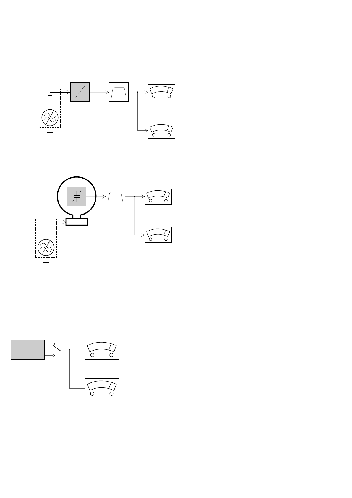
MEASUREMENT SETUP
Tuner FM
1-4
Bandpass
LF Voltmeter
e.g. PM2534
RF Generator
e.g. PM5326
DUT
250Hz-15kHz
e.g. 7122 707 48001
Ri=50
S/N and distortion meter
e.g. Sound Technology ST1700B
Use a bandpass filter to eliminate hum (50Hz, 100Hz) and disturbance from the pilottone (19kHz, 38kHz).
Tuner AM (MW,LW )
RF Generator
e.g. PM5326
Ri=50
DUT
Frame aerial
e.g. 7122 707 89001
Bandpass
250Hz-15kHz
e.g. 7122 707 48001
LF Voltmeter
e.g. PM2534
S/N and distortion meter
e.g. Sound Technology ST1700B
To avoid atmospheric interference all AM-measurements have to be carried out in a Faraday´s cage.
Use a bandpass filter (or at least a high pass filter with 250Hz) to eliminate hum (50Hz, 100Hz).
CD
Use Audio Signal Disc
DUT
L
R
SBC429 4822 397 30184
S/N and distortion meter
e.g. Sound Technology ST1700B
LEVEL METER
e.g. Sennheiser UPM550
with FF-filter
(replaces test disc 3)
SERVICE AIDS
1-5
Service Tools:
Universal Torx driver holder .................................. 4822 395 91019
Torx bit T10 150mm ............................................. 4822 395 50456
Torx driver set T6 - T20 ......................................... 4822 395 50145
Torx driver T10 extended ...................................... 4822 395 50423
Cassette:
SBC419 Test cassette CrO2 ................................. 4822 397 30069
SBC420 Test cassette Fe ..................................... 4822 397 30071
MTT150 Dolby level 200nWb/M ............................ 4822 397 30271
Compact Disc:
SBC426/426A Test disc 5 + 5A ............................ 4822 397 30096
SBC442 Audio Burn-in Test disc 1kHz ................. 4822 397 30155
SBC429 Audio Signals disc .................................. 4822 397 30184
Dolby Pro-logic Test Disc ...................................... 4822 395 10216
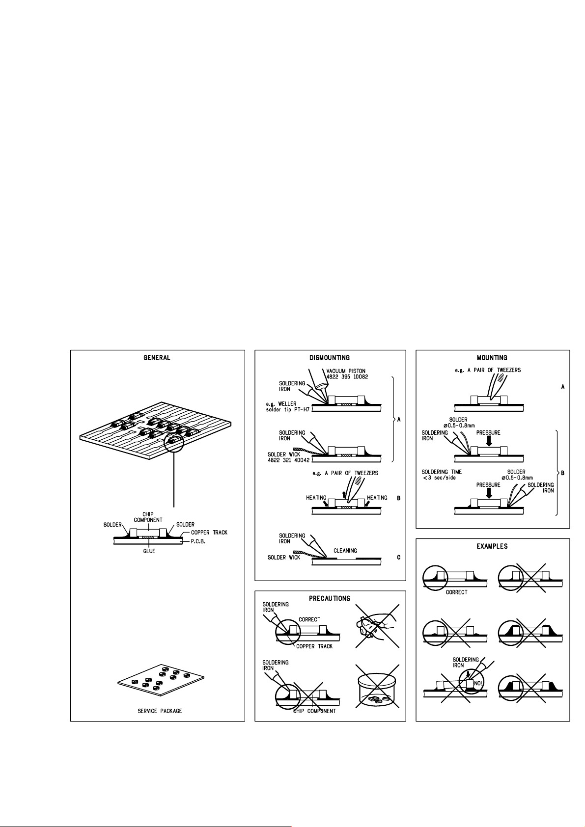
HANDLING CHIP COMPONENTS
ESD Equipment:
Anti-static table mat - large 1200x650x1.25mm ... 4822 466 10953
Anti-static table mat - small 600x650x1.25mm ..... 4822 466 10958
Anti-static wristband .............................................. 4822 395 10223
Connector box (1MΩ) ............................................ 4822 320 11307
Extension cable
(to connect wristband to conn. box) .................. 4822 320 11305
Connecting cable
(to connect table mat to conn. box) .................. 4822 320 11306
Earth cable (to connect product to mat or box) .... 4822 320 11308
Complete kit ESD3
(combining all above products) ......................... 4822 320 10671
Wristband tester .................................................... 4822 344 13999

1-6
GB
All ICs and many other semi-conductors are
susceptible to electrostatic discharges (ESD).
Careless handling during repair can reduce life
drastically.
When repairing, make sure that you are
connected with the same potential as the mass
of the set via a wrist wrap with resistance.
Keep components and tools also at this
potential.
Tous les IC et beaucoup d’autres
semi-conducteurs sont sensibles aux
décharges statiques (ESD).
Leur longévité pourrait être considérablement
écourtée par le fait qu’aucune précaution n’est
prise à leur manipulation.
Lors de réparations, s’assurer de bien être relié
au même potentiel que la masse de l’appareil et
enfiler le bracelet serti d’une résistance de
sécurité.
Veiller à ce que les composants ainsi que les
outils que l’on utilise soient également à ce
potentiel.
F
WARNING
ATTENTION
ESD
D
WARNUNG
Alle ICs und viele andere Halbleiter sind
empfindlich gegenüber elektrostatischen
Entladungen (ESD).
Unsorgfältige Behandlung im Reparaturfall kan
die Lebensdauer drastisch reduzieren.
Veranlassen Sie, dass Sie im Reparaturfall über
ein Pulsarmband mit Widerstand verbunden
sind mit dem gleichen Potential wie die Masse
des Gerätes.
Bauteile und Hilfsmittel auch auf dieses gleiche
Potential halten.
NL
Alle IC’s en vele andere halfgeleiders zijn
gevoelig voor electrostatische ontladingen
(ESD).
Onzorgvuldig behandelen tijdens reparatie kan
de levensduur drastisch doen verminderen.
Zorg ervoor dat u tijdens reparatie via een
polsband met weerstand verbonden bent met
hetzelfde potentiaal als de massa van het
apparaat.
Houd componenten en hulpmiddelen ook op
ditzelfde potentiaal.
Tutti IC e parecchi semi-conduttori sono
sensibili alle scariche statiche (ESD).
La loro longevità potrebbe essere fortemente
ridatta in caso di non osservazione della più
grande cauzione alla loro manipolazione.
Durante le riparazioni occorre quindi essere
collegato allo stesso potenziale che quello della
massa dell’apparecchio tramite un braccialetto
a resistenza.
Assicurarsi che i componenti e anche gli utensili
con quali si lavora siano anche a questo
potenziale.
WAARSCHUWING
I
AVVERTIMENTO
GB
Safety regulations require that the set be restored to its original
condition and that parts which are identical with those specified,
be used
Safety components are marked by the symbol
!
.
NL
Veiligheidsbepalingen vereisen, dat het apparaat bij reparatie in
zijn oorspronkelijke toestand wordt teruggebracht en dat onderdelen,
identiek aan de gespecificeerde, worden toegepast.
De Veiligheidsonderdelen zijn aangeduid met het symbool
!
F
Les normes de sécurité exigent que l’appareil soit remis à l’état
d’origine et que soient utiliséés les piéces de rechange identiques
à celles spécifiées.
Less composants de sécurité sont marqués
!
D
Bei jeder Reparatur sind die geltenden Sicherheitsvorschriften zu
beachten. Der Original zustand des Geräts darf nicht verändert werden;
für Reparaturen sind Original-Ersatzteile zu verwenden.
!
Sicherheitsbauteile sind durch das Symbol
markiert.
I
Le norme di sicurezza esigono che l’apparecchio venga rimesso
nelle condizioni originali e che siano utilizzati i pezzi di ricambio
identici a quelli specificati.
Componenty di sicurezza sono marcati con
!
CLASS 1
LASER PRODUCT
GB
Invisible laser radiation when open.
Avoid direct exposure to beam.
Osynlig laserstrålning när apparaten är öppnad och spärren
är urkopplad. Betrakta ej strålen.
SF
Avatussa laitteessa ja suojalukituksen ohitettaessa olet alttiina
näkymättömälle laserisäteilylle. Älä katso säteeseen!
DK
Usynlig laserstråling ved åbning når sikkerhedsafbrydere er
ude af funktion. Undgå udsaettelse for stråling.
S
Warning !
Varning !
Varoitus !
Advarse !
GB
After servicing and before returning set to customer perform a leakage
current measurement test from all exposed metal parts to earth ground to
assure no shock hazard exist. The leakage current must not exceed
0.5mA.
F
"Pour votre sécurité, ces documents doivent être utilisés par
des spécialistes agréés, seuls habilités à réparer votre
appareil en panne".
1-7
INFORMATION ABOUT LEAD-FREE SOLDERING
Philips CE is producing lead-free sets from 1.1.2005 onwards.
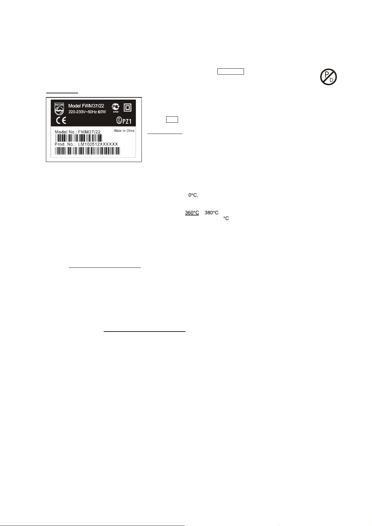
IDENTIFICATION:
Regardless of special logo (not always indicated) one must treat all sets from 1 Jan 2005 onwards, according next rules:
Example S/N:
• Use only lead-free solder alloy Philips SAC305 with order code 0622 149 00106. If lead-free solder-paste is required, please contact
the manufacturer of your solder-equipment. In general use of solder-paste within workshops should be avoided because paste is not
easy to store and to handle.
• Use only adequate solder tools applicable for lead-free solder alloy. The solder tool must be able
• Adjust your solder tool so that a temperature around
• Mix of lead-free solder alloy / parts with leaded solder alloy / parts is possible but PHILIPS recommends strongly to avoid mixed
• Use only original spare-parts listed in the Service-Manuals. Not listed standard-material (commodities) has to be purchased at
• Special information for BGA-ICs:
• For sets produced before 1.1.2005 (except products of 2004), containing leaded solder-alloy and components, all needed spare-parts
• On our website www.atyourservice.ce.Philips.com
o To reach at least a solder-temperature of 40
o To stabilize the adjusted temperature at the solder-tip
o To exchange solder-tips for different applications.
solder-joint should not exceed ~ 4 sec. Avoid temperatures above 400 otherwise wear-out of tips will rise drastically and flux-fluid
will be destroyed. To avoid wear-out of tips switch off un-used equipment, or reduce heat.
solder alloy types (leaded and lead-free).
If one cannot avoid or does not know whether product is lead-free, clean carefully the solder-joint from old solder alloy and re-solder
with new solder alloy (SAC305).
external companies.
- always use the 12nc-recognizable soldering temperature profile of the specific BGA (for de-soldering always use the lead-free
temperature profile, in case of doubt)
- lead free BGA-ICs will be delivered in so-called 'dry-packaging' (sealed pack including a silica gel pack) to protect the IC against
moisture. After opening, dependent of MSL-level seen on indicator-label in the bag, the BGA-IC possibly still has to be baked dry.
(MSL=Moisture Sensitivity Level). This will be communicated via AYS-website.
Do not re-use BGAs at all.
will be available till the end of the service-period. For repair of such sets nothing changes.
BGA-de-/soldering (+ baking instructions)
∗
Heating-profiles of BGAs and other ICs used in Philips-sets
∗
Bottom line of typeplate gives a 14-digit S/N. Digit 5&6 is the year, digit 7&8 is the week number,
so in this case 2005 wk12
So from 0501 onwards = from 1 Jan 2005 onwards
Important note
you avoid mixing solder-alloys (leaded/ lead-free). So best to always use SAC305 and the
higher temperatures belong to this.
Due to lead-free technology some rules have to be respected by the workshop during a repair:
: In fact also products of year 2004 must be treated in this way as long as
− is reached and stabilized at the solder joint. Heating-time of the
you find more information to:
For additional questions please contact your local repair-helpdesk.
You will find this and more technical information within the "magazine", chapter "workshop news".
SERVICE INSTRUCTION
Safety regulations require that after a repair, the set must be returned in its original condition. Pay in particular attention to
the following points:
· Route the wire trees correctly and fix them with the
mounted cable clamps.
· Check the insulation of the AC Power lead for external
damage.
· Check the strain relief of the AC Power cord for proper
function.
· Check the electrical DC resistance between the AC Power
Plug and the secondary side (only for sets which have a AC
Power isolated power supply):
1. Unplug the AC Power cord and connect a wire
between the two pins of the AC Power plug.
2. Set the AC Power switch to the "on" position (keep the
AC Power cord unplugged!).
3. Measure the resistance value between the pins of the
AC Power plug and the metal shielding of the tuner or
the aerial connection on the set. The reading should be
larger than 4.5 Mohm (For U.S. it should be between
4.2 Mohm and 12 Mohm).
4. Switch "off" the set, and remove the wire between the
two pins of the AC Power plug.
• Check the cabinet for defects, to avoid touching of any
inner parts by the customer.
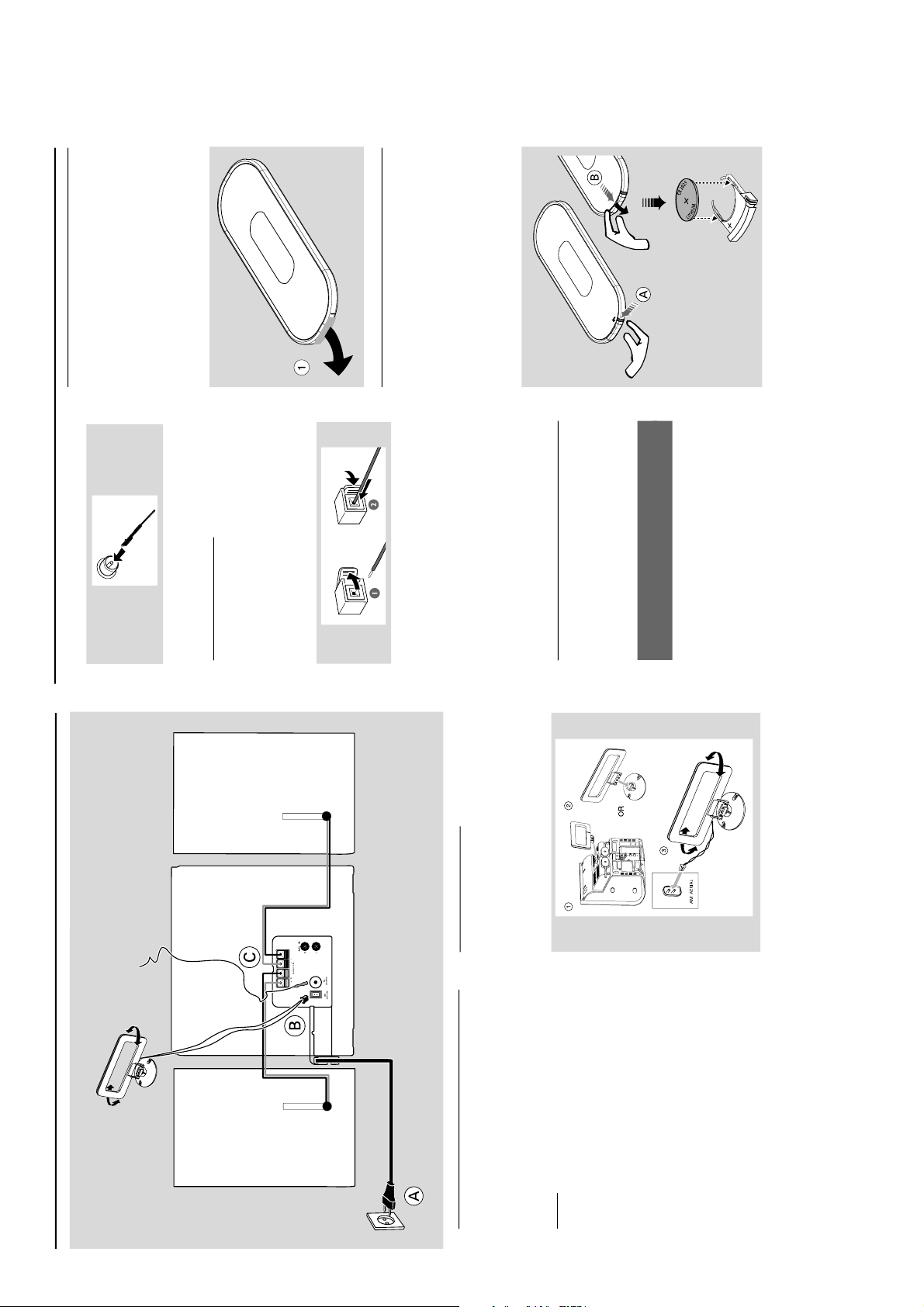
PREPARATIONS AND CONTROLS
Preparations
Rear connections
The type plate is located at the rear of the
system.
For users in the U.K.: please follow the
instructions .
A
Pow er
Before connecting the AC power cord to the
wall outlet, ensure that all other connections
have been made.
Warning!
–For optimal performance, use only the
original power cable.
– Never make or change any connections
with the power switched on.
To avoid overheating of the system, a safety
circuit has been built in. Therefore, your
system may switch to Standby mode
automatically under extreme conditions. If
this happens, let the system cool down
before reusing it (not available for all versions).
B
Antennas Connection
Connect the supplied MW loop antenna and FM
antenna to the respective terminals. Adjust the
position of the antenna for optimal reception.
MW Antenna
Position the antenna as far as possible from a TV,
VCR or other radiation source.
MW loop antenna
Speaker
(right)
Speaker
(left)
FM wire antenna
AC power cord
plastic
protective
sheet
FM Antenna
For better FM stereo reception, connect an
outdoor FM antenna to the FM ANTENNA
terminal.
C
Speakers Connection
Front Speakers
Connect the speaker wires to the SPEAKERS
terminals, right speaker to "RIGHT" and left
speaker to "LEFT", colored (marked) wire to "+"
and black (unmarked) wire to "-".
Fully insert the stripped portion of the speaker
wire into the terminal as shown.
Notes:
–For optimal sound performance, use the
supplied speakers.
– Do not connect more than one speaker to any
one pair of +/- speaker terminals.
– Do not connect speakers with an impedance
lower than the speakers supplied. Please refer to
the SPECIFICATIONS section of this manual.
Optional connection
The optional equipment and connecting cords are
not supplied. Refer to the operating instructions
of the connected equipment for details.
Connecting other equipment to your
system
Connect the audio left and right OUT terminals
of a TV, VCR, Laser Disc player, DVD player or
CD Recorder to the AUX terminals.
Note:
– If you are connecting equipment with a mono
output (a single audio out terminal), connect it to
the AUX left terminal. Alternatively, you can use a
“single to double” cinch cable (the output sound
still remain mono).
Before using the remote control
1
Pull out the plastic protective sheet.
2
Select the source you wish to control by
pressing one of the source select keys on the
remote control (for example CD, TUNER).
3
Then select the desired function (for example
2 ; , ¡ ™ , ).
Replacing battery (lithium
CR2025) into the remote control
1
Pull out the knob A slightly to the left.
2
Pull out the battery compar tment B .
3
Replace a new battery and fully inser t the
battery compar tment back to the original
position.
CAUTION!
Batteries contain chemical substances, so
they should be disposed of properly.
Preparations
1-8
PREPARATIONS AND CONTROLS
)
1
3
4
6
7
8
9
5
!
0
2
^
(
1
!
7
0
8
*
%
@
3
#
$
&
5
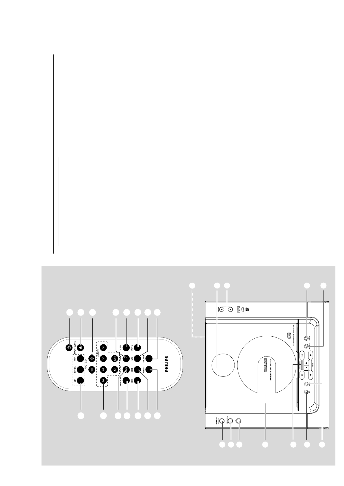
Controls
Controls on the system and
remote control
1
STANDBY-ON/ ECO POWER (B)
– switches the system on or to Eco Power
standby/normal standby with clock display.
2
Display screen
– shows the status of the system.
3
OPEN • CLOSE √/
– opens/closes the CD door.
4
IR
– remote sensor
5
VOLUME (3 / 4 ) (+/-)
– adjusts the volume level.
– adjusts the hours and minutes for the clock/timer
function.
6
CD Door
7
Mode Selection
ALBUM/ TUNE/ALBUM -/+ ( 5 / 6 )
for TUNER ........ tunes to a station
for CD/MP3-CD fast searches back and
forward within a track/disc (press
and hold).
for MP3-CD .....skips to the beginning of a
current/previous/subsequent
album.
9 ............................. stops disc playback or erases a
disc programme.
2 ; ................... star ts or interrupts playback.
PRESET (
J
/
K
)
for TUNER ........ selects a preset radio station.
for CD/MP3 -CD skips to the beginning of a
current/previous/subsequent
track
8
DBB (Dynamic Bass Boost)
– enhances the bass.
9
BAND
– selects a waveband.
0
PROGRAM
for CD/MP3-CD programmes tracks and
reviews the programme.
for TUNER ........ programmes tuner stations.
!
SOURCE
– selects the respective sound source for CD/
TUNER/ AUX.
Notes for remote control:
– First select the source you wish to
control by pressing one of the source select
keys on the remote control (for example
CD, TUNER).
– Then select the desired function (for
example
2 ;
,
J
,
K
).
@
DISPLAY/CLOCK
– sets the clock function.
– displays disc information during playback.
#
TIMER
– activates/ deactivates or sets the timer function.
$
SLEEP
– activates/deactivates or selects the sleeper time.
%
DSC (Digital Sound Control)
– selects sound characteristics: ROCK/ JAZZ/
POP/ CLASSIC.
^
RDS
–for tuner, displays RDS information.
&
MUTE
– interrupts and resumes sound reproduction.
*
REPEAT
– repeats a track/disc programme/entire disc.
(
SHUFFLE
– plays disc tracks in random order.
)
n
–connects headphones
1-9

TROUBLESHOOTING
Important notes for users in the
U.K.
Mains plug
This apparatus is fitted with an approved 13
Amp plug. To change a fuse in this type of plug
proceed as follows:
1
Remove fuse cover and fuse.
2
Fix new fuse which should be a BS1362 3 Amp,
A.S.T.A. or BSI approved type.
3
Refit the fuse cover.
If the fitted plug is not suitable for your socket
outlets, it should be cut off and an appropriate
plug fitted in its place.
If the mains plug contains a fuse, this should
have a value of 3 Amp. If a plug without a fuse
is used, the fuse at the distribution board
should not be greater than 3 Amp.
Note: The severed plug must be disposed of to
avoid a possible shock hazard should it be
inserted into a 13 Amp socket elsewhere.
How to connect a plug
The wires in the mains lead are coloured with
the following code: blue = neutral (N),
brown = live (L).
∂ As these colours may not correspond with the
colour markings identifying the terminals in
your plug, proceed as follows:
– Connect the blue wire to the terminal
marked N or coloured black.
– Connect the brown wire to the terminal
marked L or coloured red.
– Do not connect either wire to the earth
terminal in the plug, marked E (or e) or
coloured green (or green and yellow).
Before replacing the plug cover, make certain
that the cord grip is clamped over the sheath
of the lead - not simply over the two wires.
Copyright in the U.K.
Recording and playback of material may
require consent. See Copyright Act 1956 and
The Performer’s Protection Acts 1958 to 1972.
Norge
Typeskilt finnes på apparatens underside.
Observer: Nettbryteren er sekundert
innkoplet. Den innebygde netdelen er
derfor ikke frakoplet nettet så lenge
apparatet er tilsluttet nettkontakten.
For å redusere faren for brann eller elektrisk
støt, skal apparatet ikke utsettes for regn eller
fuktighet.
Italia
DICHIARAZIONE DI CONFORMITA’
Si dichiara che l’apparecchio MCM240 Philips
risponde alle prescrizioni dell’ar t. 2 comma 1
del D.M. 28 Agosto 1995 n. 548.
Fatto a Eindhoven
Philips Consumer Electronics
Philips, Glaslaan 2
5616 JB Eindhoven, The Netherlands
CAUTION
Use of controls or adjustments or
performance of procedures other than
herein may result in hazardous
radiation exposure or other unsafe
operation.
VAROITUS
Muiden kuin tässä esitettyjen
toimintojen säädön tai asetusten
muutto saattaa altistaa vaaralliselle
säteilylle tai muille vaarallisille
toiminnoille.
Troubleshooting
WARNING
Under no circumstances should you try to repair the system yourself, as this will invalidate the
warranty. Do not open the system as there is a risk of electric shock.
If a fault occurs, first check the points listed below before taking the system for repair. If you
are unable to remedy a problem by following these hints, consult your dealer or Philips for
help.
“NO DISC” is displayed.
Radio reception is poor.
The system does not react when buttons
are pressed.
Sound cannot be heard or is of poor
quality.
The left and right sound outputs are
reversed.
The remote control does not function
properly.
The timer is not working.
The Clock/Timer setting is erased.
Insert a disc.
Check if the disc is inserted upside down.
Wait until the moisture condensation at the lens
has cleared.
Replace or clean the disc, see “Maintenance”.
Use a finalised CD-RW or a correct MP3-CD
format disc.
If the signal is too weak, adjust the antenna or
connect an external antenna for better
reception.
Increase the distance between the Micro HiFi
System and your TV or VCR.
Remove and reconnect the AC power plug and
switch on the system again.
Adjust the volume.
Disconnect the headphones.
Check that the speakers are connected correctly.
Check if the stripped speaker wire is clamped.
Make sure the MP3-CD was recorded within
32~256 kbps bit rate with sampling frequencies
at 48 kHz, 44.1 kHz or 32 kHz.
Check the speaker connections and location.
Select the source (CD or TUNER, for example)
before pressing the function button ( 2; ,¡ ,
™ ).
Reduce the distance between the remote
control and the system.
Insert the battery with its polarities
(+/– signs) aligned as indicated.
Replace the battery.
Point the remote control directly toward
IR sensor on the front of the system.
Set the clock correctly.
Press TIMER to switch on the timer.
Power has been interrupted or the power cord
has been disconnected. Reset the clock/timer.
Problem
Solution
1-10

2-1
2-1
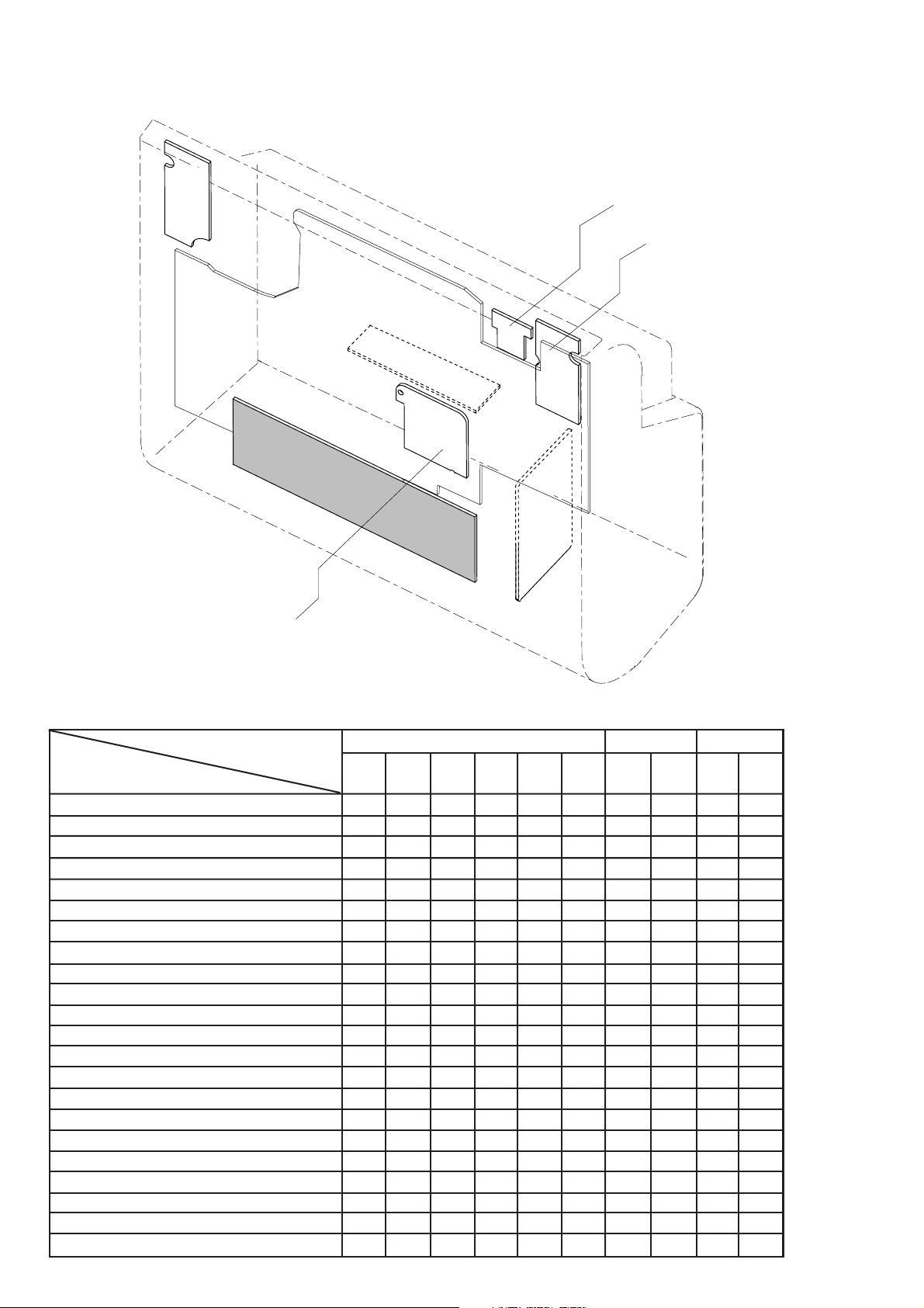
DISMANTLING INSTRUCTIONS
Dismantling of the Rear Portion
1) Remove 11 screws A and B as indicated to remove the
Rear Cabinet.
2) Remove 2 screws C as indicated to loosen the Speaker
Wire Holder.
3) Remove 2 screws D as indicated to loosen the Speaker
Board .
4) Remove 2 screws E as indicated to loosen the AUX IN
jack.
Dismantling of the Front Boards and CD Door
1) Loosen 3 screws G each to remove the CD Mechanism
Holder Bracket.
2) Loosen 7 screws F1 and F2 as indicated to remove the
Main Board.
3) Remove 3 screws H as indicated to loosen the Gear Motor
Module.
4) Loosen 4 screws I (see Figure 3) to remove the Key_C
Board.
5) Loosen 2 screws J (see Figure 3) to remove the Display
Board.
DISMANTLING INSTRUCTIONS
Repair Hints & Service Positions
Note: The flex cables are very fragile, care should be taken
not to damage them during repair. After repair, be
very sure that the flex cables are inserted properly
into the flex sockets before encasing, otherwise faults
may occurs.
Service position A
Service position B
Figure 1
Figure 3
6) Loosen 4 screws K (see Figure 3) to remove the Key_B
Board.
7) Loosen 8 screws L (see Figure 3) to remove the Key_A
Board.
8) Loosen 8 screws M (see Figure 3) to remove the Door Eject
Lever Bracket Right/Left, then remove CD door.
Figure 4
Figure 5
Service position C
Figure 2
Figure 6

SERVICE TEST PROGRAM
3-1
To start service test program
hold VOL DN button
depressed then STOP
button depressed in
standby mode
3-1
Display shows the
ROM version
"VX--XX OTP MCM240
XX-XX-2005"
V refers to Version
X--XX refers to Software version number of the uProcessor
eg. V1-7E
XX-XX-200X
refers to Date, eg. 25-5-2005

SET BLOCK DIAGRAM
4-1
4-1

SET WIRING DIAGRAM
5-1
5-1

6-1
POWER BOARD
6-1
Printed Circuit Board - Side A
The board is not intented to be repaired on component level.
Circuit Diagram and Printed Circuit Board drawings
are published for orientation only.
In case of defects please replace the entire board.
The board can be ordered with codenumber "9940 000 02866" for /21/21M/37.
"9940 000 02867" for /22/25.
Printed Circuit Board - Side A

CIRCUIT DIAGRAM
6-2
6-2

7-1
7-1
LAYOUT DIAGRAM - OPEN/CLOSE BOARD
TOP SIDE
KEY BOARD
The board is not intented to be repaired on component level.
Circuit Diagram and Printed Circuit Board drawings
are published for orientation only.
In case of defects please replace the entire board.
The board can be ordered with codenumber "9940 000 02868" for /21/21M/37.
"9940 000 02869" for /22/25.
LAYOUT DIAGRAM - OPEN/CLOSE BOARD
BOTTOM SIDE
LAYOUT DIAGRAM - VOLUME BOARD
TOP SIDE
LAYOUT DIAGRAM - VOLUME BOARD
BOTTOM SIDE

LAYOUT DIAGRAM - KEY BOARD
TOP SIDE
7-2
7-2
LAYOUT DIAGRAM - KEY BOARD
BOTTOM SIDE

CIRCUIT DIAGRAM
7-3
7-3

8-1
+
−
MAIN BOARD
8-1
BLOCK DIAGRAM - AM/FM IF + FM STEREO DETECTOR
TA2099N
TABLE OF CONTENTS
Internal IC Diagram ............................................... 8-1 to 8-3
Main Board Layout Top View ........................................... 8-4
Main Board Layout Bottom View ..................................... 8-5
Circuit Diagram - MCU Part ............................................. 8-6
Circuit Diagram - CD Part ................................................ 8-7
Circuit Diagram - MP3 Part ............................................. 8-8
Circuit Diagram - Amp Part.............................................. 8-9
Circuit Diagram - Tuner Part.......................................... 8-10
Layout Diagrams ........................................................... 8-11
BLOCK DIAGRAM - 2-CHANNEL AUDIO
AMPLIFIER TFA9842J
V
CC
9
4
IN1+
60 kΩ
1
IN2+
60 kΩ
CIV
MODE
3
V
7
TFA9842J
REF
STANDBY
MUTE
ON
SHORT-CIRCUIT
AND
TEMPERATURE
PROTECTION
V
CC
0.5V
CC
PIN CONFIGURATION - 2-CHANNEL AUDIO
AMPLIFIER TFA9842J
8
OUT1
+
IN2
1
2
OUT2
6
SVR
OUT2−
OUT1+
CIV
IN1+
GND
SVR
MODE
V
CC
2
3
4
5
6
7
8
9
TFA9842J
GND
5

8-2 8-2
BLOCK DIAGRAM - CD Player Processor
TC94A14FA
48
DV
49
SS3
Clock
generator
1-bit
DAC
DV
DD3
DV
RO
LO
50
51
52
53
LPF
PW M
Servo control
A/D
D/A
BLOCK DIAGRAM - SYSTEM ELECTRONIC VOLUME
TC9422N
33 47 46 45 44 43 42 41 40 39 38 37 36 35 34
TEZI
32
TEI
31
SBAD
30
FEI
29
28
RFRP
DV
ZDET
V
BUS0
BUS1
BUS2
BUS3
BUC
/CCE
/RST
V
SS3
SS5
DD5
54
55
56
57
58
59
60
61
62
63
64
1 16 2 3 4 5 6 7 8 9 10 11 12 13 14 15
Micro-
controlle r
interface
Audio out
circuit
Address
circuit
16 k
RAM
Digita l output
ROM
Digita l equalizer
RAM
adjustment circuit
CLV servo
Synchronous
guarantee
EFM
decoder
Sub code
decoder
automatic
Data
slicer
VCO
PLL
TMAX
27
26
25
24
23
22
21
20
19
18
17
RFZI
RFCT
V
DD3
RFI
SLCO
V
SS3
VCOF
PV
REF
LPFO
LPFN
TMAX

8-3
BLOCK DIAGRAM - MICROCONTROLLER UNIT
TMP87PP23F
8-3

LAYOUT DIAGRAM - MAIN BOARD
TOP SIDE
8-4
8-4

LAYOUT DIAGRAM - MAIN BOARD
BOTTOM SIDE
8-5
8-5

CIRCUIT DIAGRAM - MAIN BOARD
MCU PART
8-6
8-6

CIRCUIT DIAGRAM - MAIN BOARD
CD PART
8-7
8-7

CIRCUIT DIAGRAM - MAIN BOARD
MP3 PART
8-8 8-8

CIRCUIT DIAGRAM - MAIN BOARD
AMP PART
8-9 8-9

CIRCUIT DIAGRAM - MAIN BOARD
TUNER PART
8-10
8-10

8-11 8-11
LAYOUT DIAGRAM - HEADPHONE BOARD
TOP SIDE
LAYOUT DIAGRAM - HEADPHONE BOARD
BOTTOM SIDE
LAYOUT DIAGRAM - SPEAKER BOARD
TOP SIDE
LAYOUT DIAGRAM - SPEAKER BOARD
BOTTOM SIDE
LAYOUT DIAGRAM - MOTOR BOARD
LAYOUT DIAGRAM - ANTENNA BOARD
LAYOUT DIAGRAM - SWITCH BOARD
LAYOUT DIAGRAM - LED BOARD
TOP SIDE
LAYOUT DIAGRAM - LED BOARD
BOTTOM SIDE

SET EXPLODED VIEW
9-1
9-1
031
68
43
47
008
68
032
029
025
027
61
64
68
43
63
59
38
022
027
021
020
024
019
43
43
26
016
19
018
19
41
30
28
017
51
68
68
43
028
64
63
027
026
024
012
011
12
007
013
48
28
023
004
002
28
015
19
014
009
5
12
006
005
5
003
MCM240 SCREW LIST
HARDEN SCREW BTTB 3x8mm AB68
63
61
MACHINE SCREW MS/KH 3x8mm HD 5mm
59
NUT ID:3 OD:5.5 T:2.3mm
SCREW TA/BWH 3x10mm (HD:12mm)
51
SELF-TAPPING SCREW TA/WH 3x12mm
48
47
HARDEN SCREW TT/PH 3x4 2
HARDEN SCREW BTTB 3x12 AB
43
41
MACHINE SCREW MS/BH 3x4 mm
28
19
HARDEN SCREW BTTB 2x8 MC
12
SELF-TAPPING SCREW TA/KH 2.6x8mm
5
SELF-TAPPING SCREW TA/KH 1.4x3.5 mm
ITEM
9
4SELF-TAPPING SCREW TA/WH 3x10mm(H D:10mm)
2
2
1
2
14
1
2SELF-TAPPING SCREW TB/KH 3x8 HD5mm 38
15HARDEN SCREW BTTB 2.6x8mm MC
17
8
6
QTYDESCRIPTION
001

9-2 9-2
MECHANICAL & ACCESSORIES PARTSLIST
001 994000002809 CD DOOR LENS W/HOT FOIL 994000000275 RCA PIN JACK
002 994000002805 CD DOOR COVER -LEFT 994000000317 AC CORD CUL 6FT /37
003 994000002806 CD DOOR COVER -RIGHT 994000000512 AC CORD BS PLUG 2M /25
004 994000002804 CD DOOR CARRIER 994000002819 AC CORD 2.4M /21/21M/22
005 994000002811 CONTL PANEL LENS W/HOT FOIL 994000002824 REMOTE CONTROL UNIT
006 994000002803 FRONT CABINET /21/21M/30 994000002825 SPEAKER BOX L+R
006 994000002863 FRONT CABINET /22/25
006 994000002831 FRONT CABINET /37
007 994000000305 SENSOR LENS
008 994000000321 POWER /CD OPEN BUTTON
009 994000000322 VOL +/- BUTTON
011 994000002822 CD MECHANISM DA23Z1
012 994000002816 SHOCK ABSORBER (BLACK)
013 994000002817 SHOCK ABSORBER (GRAY) Note: Only these parts mentioned in the list are
014 994000000324 FUNCTION BUTTON D./B./S./P./S. normal service parts.
!
!
!
ELECTRICAL PARTSLIST
C317 994000002856 E.CAP 4700UF 16V +-20% Q208 994000002834 TRANSISTORS MMBT3904LT1
C319 994000001346 E.CAP 4700UF 25V +-20% Q209 994000002834 TRANSISTORS MMBT3904LT1
CF201 994000000245 BAND PASS FILTER Q210 994000002834 TRANSISTORS MMBT3904LT1
CF204 994000002857 CERAMIC FILTER SFU450B Q211 994000002834 TRANSISTORS MMBT3904LT1
FS300 994000000588 FUSE T800mA/250V /21/21M/37 Q212 994000002834 TRANSISTORS MMBT3904LT1
FS301 994000000585 CERAMIC FUSE 2A/250V Q213 994000002834 TRANSISTORS MMBT3904LT1
FS302 994000000586 GLASS FUSE 3.15A/250V Q214 994000002835 TRANSISTORS MMBT3906LT1
FS303 994000002865 SUBMINI. FUSE 200mA/250V /22 Q215 994000002834 TRANSISTORS MMBT3904LT1
IC1 994000002842 IC MM1469PH Q301 994000001193 TRANSISTORS KSB772YS
IC101 994000002844 IC TA2157FN Q302 994000002834 TRANSISTORS MMBT3904LT1
IC102 994000002849 IC TC94A14FAG Q402 994000002834 TRANSISTORS MMBT3904LT1
IC103 994000002853 IC XC61FC3012MR Q403 994000002834 TRANSISTORS MMBT3904LT1
IC105 994000001197 IC KA7805 Q404 994000002834 MMBT3904LT1/21/21M/37
IC201 994000002846 IC TC9257F Q404 994000002835 MMBT3906LT1 /22/25
IC202 994000002843 IC TA2099N Q405 994000002834 TRANSISTORS MMBT3904LT1
!
!
!
!
015 994000000323 FUNCTION BUTTON STOP/PLAY
016 994000002837 LCD DISPLAY
017 994000002814 DRIVE BELT
018 994000002808 DRIVER PULLEY GEAR
019 994000002807 DRIVING GEAR
020 994000002832 MOTOR BRACKET
021 994000002818 DOOR MOTOR PULLY
022 994000002815 DC MOTOR 5V
023 994000000597 TRANSFORMER 120/230V /21/21M
023 994000000278 TRANSFORMER 230V /22/25
!
!
023 994000000316 TRANSFORMER EI-57 120V /37
024 994000000284 RUBBER FOOT
025 994000000281 RCA JACK BD 2P (RD/WH)
026 994000000592 REAR CABINET /21
026 994000000291 REAR CABINET /22/25
026 994000000319 REAR CABINET /37
027 994000000283 SPEAKER HOLDER
028 994000002813 RUBBER FOOT 24x11x1.6mm
029 994000002812 UNIT STAND
031 994000002823 AM/FM ANT 75R ASS'Y PACKING
IC203 994000002864 IC BU1924F /22/25 Q406 994000002834 TRANSISTORS MMBT3904LT1
IC204 994000002848 IC TC9422AFG Q602 994000002834 TRANSISTORS MMBT3904LT1
IC301 994000002841 IC KA7810 Q900 994000002862 TRANSISTORS 2W 8050C
IC302 994000000253 IC KA7808 R301 994000002854 FUSE RES. 2.2R 1W +-5%
IC303 994000000277 IC LM78L05 R462 994000002855 FUSE RES. 27R 1W +-5%
!
!
IC401 994000002852 IC TMP87PP23F (OTP) REM401 994000001239 OPTIC SENSER (OPTO..)
IC402 994000002845 IC TA7291S RF201 994000000256 TUNER (MITSUMI) FE450-G01
IC403 994000002853 IC XC61FC3012MR RL301 994000000264 RELAY 9V 10A /22/25
!
IC501 994000002851 IC TC94A34FG-006 SW401 994000000274 TACT SWITCH
IC502 994000002847 IC TC9404FN SW402 994000000274 TACT SWITCH
IC503 994000002839 IC H1117SJ-3.3V SW403 994000000274 TACT SWITCH
IC504 994000002838 IC BA15BC0FP SW404 994000000274 TACT SWITCH
IC601 994000000249 IC BA4558F SW405 994000000274 TACT SWITCH
IC602 994000000367 IC TFA9842J SW406 994000000274 TACT SWITCH
JK601 994000000257 PHONE JACK 7PIN SW407 994000000274 TACT SWITCH
JK602 994000000315 SPK JACK (R/B/R/B) SW408 994000000274 TACT SWITCH
LED401 994000001233 LED LAMP (RED) SW409 994000000274 TACT SWITCH
LED402
994000000267 LED LAMP 5mm (BLUE) SW410 994000000274 TACT SWITCH
LED403 994000000266 LED LAMP 3mm (BLUE) SW411 994000000274 TACT SWITCH
Q102 994000002839 IC H1117SJ-3.3V SW412 994000000274 TACT SWITCH
032 994000000307 SPEAKER WIRE HOLDER
Q201 994000002833 TRANSISTORS 9018G SW413 994000000274 TACT SWITCH
Q202 994000002834 TRANSISTORS MMBT3904LT1 SW414 994000000274 TACT SWITCH
Q203 994000002834 TRANSISTORS MMBT3904LT1 SW601 994000000273 MICRO SWITCH 1120B
Q206 994000002834 TRANSISTORS MMBT3904LT1 SW602 994000000273 MICRO SWITCH 1120B
Q207 994000002834 TRANSISTORS MMBT3904LT1 T201 994000002858 I.F.T 7mm #7M1A2186F (BLK)

9-3
ELECTRICAL PARTSLIST
T202 994000002859 I.F.T 7mm #7M4A1975R (ORANGE)
T203 994000002861 I.F.T 7mm A049 (YELLOW)
T302 994000000262 TRANSFORMER AC230V /22/25
VD201 994000002836 VARICAP DIODE 1SV-149
VD202 994000002836 VARICAP DIODE 1SV-149
!
994000002866 POWER BD ASS'Y /21/21M/37
994000002867 POWER BD ASS'Y /22/25
994000002868 KEY BD ASS'Y /21/21M/30/37
994000002869 KEY BD ASS'Y /22/25
9-3
Note: Only these parts mentioned in the list are
normal service parts.
 Loading...