

Page 1
PLASMA DISPLAY
USER’S MANUAL
KPP-4200D
Proper use guarantees
product life.
Before using the product,
PLEASE READ this owners
manual carefully and follow all
INSTRUCTIONS.
Page 2
2
This Owner’s Manual presents safety precautions and instructions on how to use
the product. After reading it thoroughly, use the product safely.
Keep this manual where the user can see it easily.
Failure to comply with warnings and cautions for the safe use of electric
appliances may cause fire or human injury.
• 42” super-wide, 8cm Ultra Slim Wall-mounting Monitor
PLASMA opens new Monitor era with advanced plasma technology - 8cm ultra slim Monitor allows installing in
narrow space. Weighs only 30Kg
• DVD Direct Connection / Outstanding Picture Quality Digital
Broadcasts Receive (SD Grade)
DVD can be directly connected to the unit so that you can view clear digital images. You can enjoy even
higher quality images by connecting digital broadcasting receiver with which digital broadcasts can be
viewed.
•
PC Direct Connection
PC can be connected to the PDP without a separate device, and can be used as a monitor so that the
effect of presentation is maximized, making it more popular in various presentations and exhibitions.
•
PDP Monitor with Minimized Noise
Although PDP Monitor had an outstanding picture quality, there has previously been a problem with the
noise caused by the internal cooling fan. PLASMA monitors no longer require cooling fans. The
introduction of self air circulation system, which has excellent heat transference, eliminates any fan noise.
•
160º Wide-Angle Viewing Area
•
Flat Panel with No Distortion or Color Blurring
Since Plasma Monitors have no problems such as distortion, blurring or flickering like CRT type
televisions, you can enjoy Home Theatre with super speaker sound.
•
Various Video Control
- 11 Languages OSD - 20 Step screen zooming function - Full-screen still function
- Various aspect ratio (16:9, Panorama, Normal, Enlarge LB, Enlarge LBS)
•
3 Way 6 Speaker Stereo Sound System
•
Worldwide :
NTSC, PAL, SECAM / Free Volt (100-240V 50/60Hz)power source.
Features
Features
Page 3
FCC RF INTERFERENCE ST
FCC RF INTERFERENCE STAA
TEMENT
TEMENT
NOTE :
This equipment has been tested and found to comply with the limits for a
Class B digital device, pursuant to Part 15 of the FCC Rules. These limits
are designed to provide reasonable protection against harmful
interference in a residential installation.
This equipment generates, uses and can radiate radio frequency energy
and, if not installed and used in accordance with the instructions, may
cause harmful interference to radio communications. However, there is no
guarantee that interference will not occur in a particular installation.
If this equipment does cause harmful interference to radio or television
reception which can be determined by turning the equipment off and on,
the user is encouraged to try to correct the interference by one or more of
the following measures.
- Reorient or relocate the receiving antenna.
- Increase the separation between the equipment and receiver.
- Connect the equipment into an outlet on a circuit different from that to
which the receiver is connected.
- Consult the dealer or an experienced radio tv technician for assistance .
- Only shielded interface cables should be used.
Finally, any changes or modifications to the equipment by the user not
expressly approved by the grantee or manufacturer could void the users
authority to operate such equipment.
Page 4
Always obey all
safety messages.
•All the safety and
operating
instructions should
be read before the
product is operated.
If anything strange
happens, unplug
this product from
the wall outlet.
•Do not disassemble
or replace any parts
of the monitor.
Refer to a qualified
service technician
for repair.
Safety Precautions
4
W ARNING
You can be killed
or seriously
injured if you do
not follow
instructions.
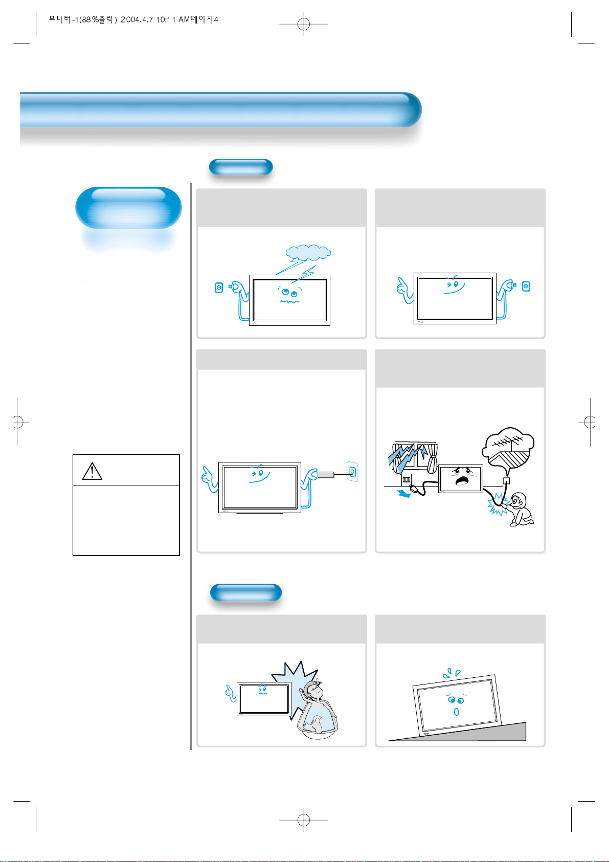
During a lightning storm, or when it is left
unattended and unused for a long period
of time, unplug it from the wall outlet.
It can result in fire.
When unplugging your monitor, always
grip plug firmly and pull straight out from
the power point. Don't pull by the cord.
It can result in fire or electric shock due to
damaged power cord.
This product must be properly grounded.
• Improper grounding may cause malfunction or
electric shock.
• When proper grounding is not possible, install a
circuit breaker.
• Do not ground to gas pipe, water pipe, lightning
rod, or telephone line.
During a lightning storm, unplug the
monitor from the wall outlet, and do not
touch the antenna.
It can cause fire or electric shock.
Power
Installation
Do not use this product in the
neighborhood of a bath or shower.
It can result in electric shock or fire.
Do not place this monitor on an unstable
cart, stand, or table
It may cause the product and cart to overturn,
damaging equipment or causing possible injury.
Page 5
5
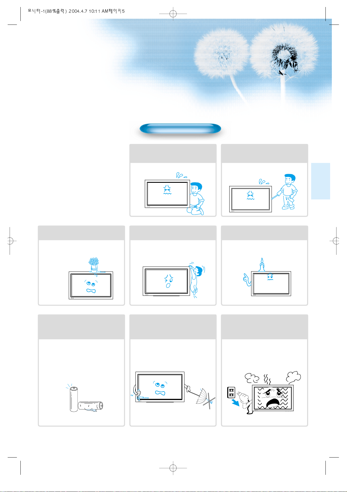
While Using Monitor
Do not open cover (or back) because
high voltage is present within the
monitor’s enclosure.
It may cause electric shock.
Never push objects of any kind into
this product through openings at the
back of monitor.
It may cause fire or electric shock.
No objects filled with liquids, such as
vases, shall be placed on the monitor.
Spilled liquids may cause electric shock or
fire.
Do not allow children to play or hang
on the monitor.
These actions may tip it over, causing
personal injury.
Do not place candle or lighted
cigarette on the monitor.
If these fall into the inside of the monitor, it
may cause fire or explosion.
Do not disassemble batteries, and
do not allow children to swallow
them.
Heavy metal may contaminate environment,
and can be harmful or detrimental to human
health. (When children swallow the batteries,
go to hospital and consult with a doctor.)
Batteries could explode if aligned incorrectly.
Align the batteries according to the (+) and (-)
indication inside the case.
Do not spray water on the monitor or
wipe with damp cloth.
It may cause electric shock or fire.
Unplug the monitor from the wall
outlet when smoke or burning smell
occurs. Refer immediately to a
qualified service technician.
In the case of continuous use, it may cause
fire or electric shock.
Page 6
Always obey all
safety messages.
• All the safety and
operating instructions
should be read before
the product is
operated.
Safety Precautions
6
Power
Installation
CAUTION
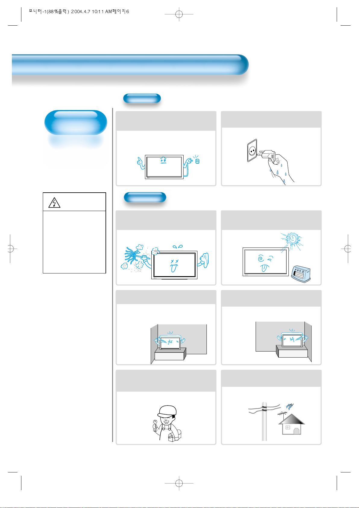
When moving your monitor, remove the
power plug, antenna, and cables, and be
sure it is moved by two people.
Failure to follow this instruction can result in
electric shock or personal injury.
Do not touch the power plug with wet
hands when plugging or unplugging.
It can result in a risk of electric shock.
Do not install the product where it will be exposed to
direct sunlight, and the product should not be
near heat sources such as radiators, stoves, etc.
It may cause malfunction.
Do not install in areas where there is oil,
smog, moisture or dust .
It may cause malfunction.
For proper ventilation, ensure the product is
positioned more than 10cm from the wall.
Due to the increase of temperature inside the
Monitor, it may cause fire.
Do not place the monitor where
ventilation is not ensured.
Due to the increase of temperature inside the
Monitor, it may cause fire.
IIf you wish to install this product on the
wall or ceiling, refer to an installation
professional.
Failure to do so may cause personal injury and
damage to this product.
When using an outside antenna system, do not
install it in the vicinity of overhead power lines.
When antenna touches such power lines, it may
cause electric shock and damage to the unit.
You may be injured,
or this product or
your property can
be damaged if you
don't follow
instructions.
Page 7
77
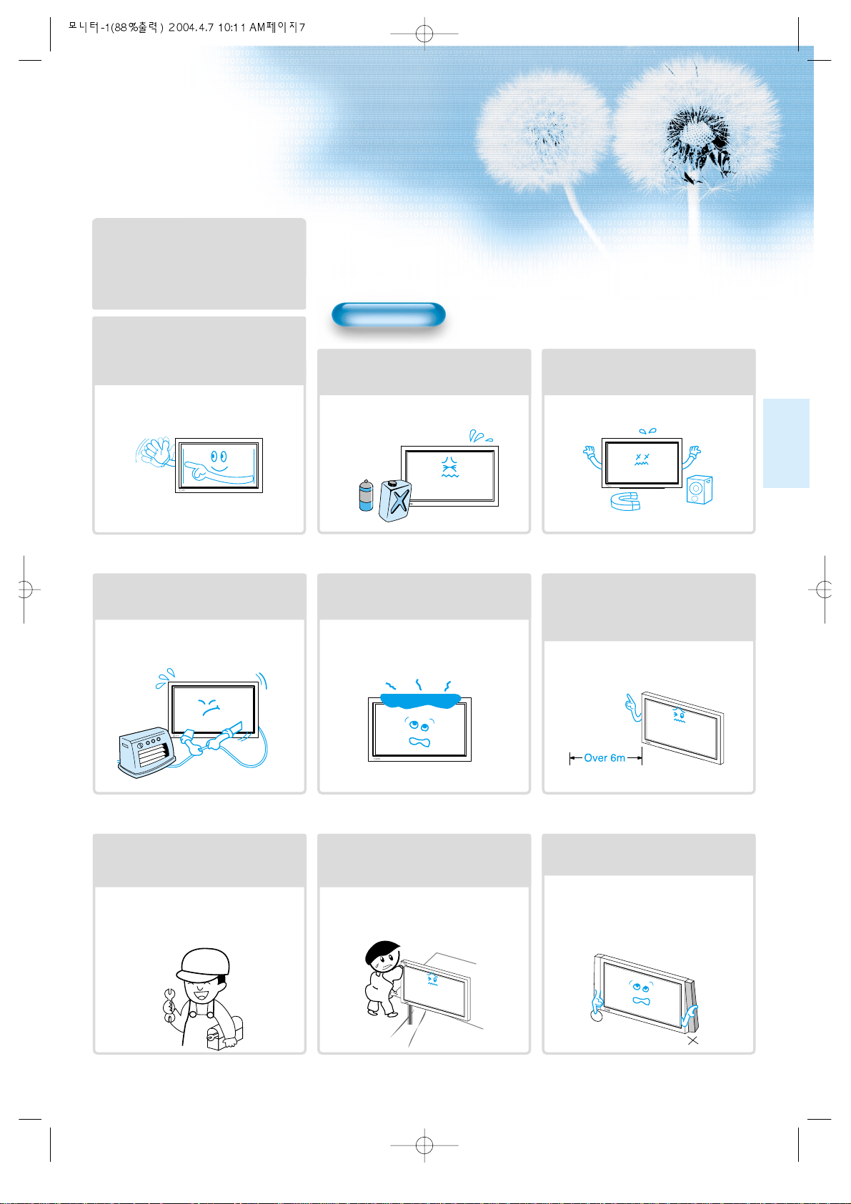
During Use
Do not wipe the monitor using a
cloth damped with chemicals
(benzene, thinner, etc.).
Monitor appearance may be marred.
(Unplug the power plug and wipe with soft
cloth.)
Do not place the monitor near
magnets, speakers, or telephones.
It can cause a change in the color tone of
the screen.
Do not place any object or cover on
the monitor.
In an event of improper ventilation, the
monitor may be overheated causing fire.
Do not place heavy objects or heat
sources on the power cord.
It may damage the power cord, causing fire
or electric shock.
When watching the TV, the distance
between the Monitor screen and
your eye should be 5~7 times as the
diagonal distance of the Monitor.
Watching the TV for a long time may affect
your eye sight.
When cleaning of the inside of the
monitor is required, consult a
qualified service technician.
When the monitor is not cleaned for a long
period of time, dust in it may cause fire or
malfunction.
When the monitor is placed on a cart
or table, the front of the Monitor
should not overhang the edge.
Imbalance may cause the monitor to fall
resulting in personal injury or equipment
malfunction and damage.
Do not grip or lift by speakers when
moving the monitor.
When moving the monitor while gripping the
speakers, speakers may become detached
from the monitor due to its weight, causing
personal injury.
Do not allow a still picture to be
displayed for an extended period, as
this can cause a permanent ghost
image to remain on the Wide Plasma
Display.
Examples of still pictures include logos,
video games, computer images, teletext
and images displayed in 4:3 mode.
Warranty does not cover any damage
caused by image retention.
The plasma display panel consists
of fine cells. Although the panels are
produced with more than 99.9
percent active cells, there may be
some cells that do not produce light
or remain lit.
Page 8
8
IN
P
U
T
S
E
L
E
C
T
P
O
W
E
R
D
IS
P
L
A
Y
Z
O
O
M
-
P
IC
T
U
R
E
M
O
D
E
S
C
R
E
E
N
M
O
D
E
F
R
E
E
Z
E
M
U
T
E
S
O
U
N
D
M
O
D
E
S
L
E
E
P
Z
O
O
M
+
M
E
N
U
V
O
L
V
O
L
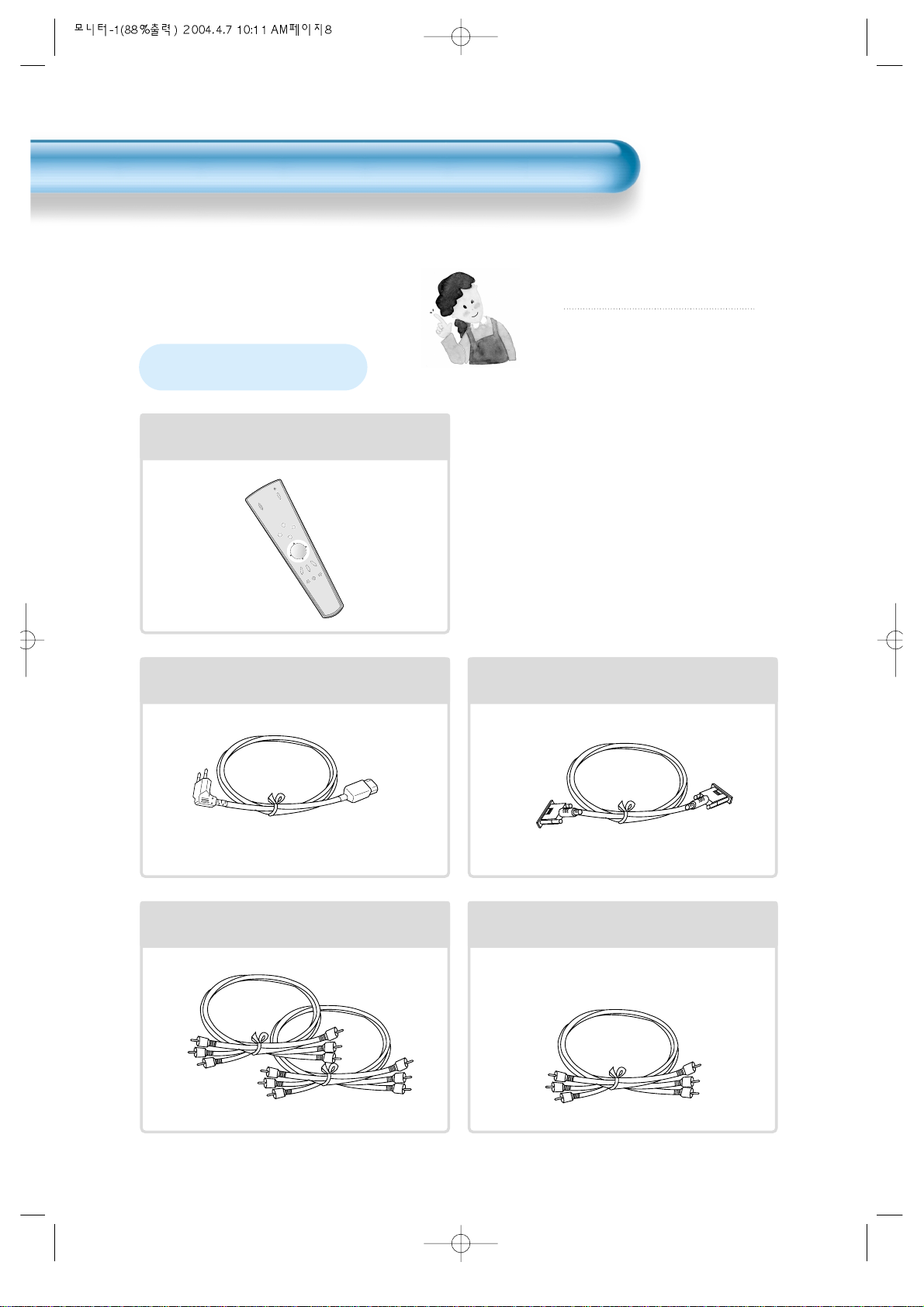
Remote Control
1 UNIT
AC Cable
1 UNIT
PC(15pin) Cable
1 UNIT
A/V Cable
2 UNITS
Audio Cable
1UNIT
Note
Check to be sure that the following items are
packed with your Monitor. Please contact
retailer if any are missing.
Checking Accessories
Supplied Accessories
Page 9
9
Note
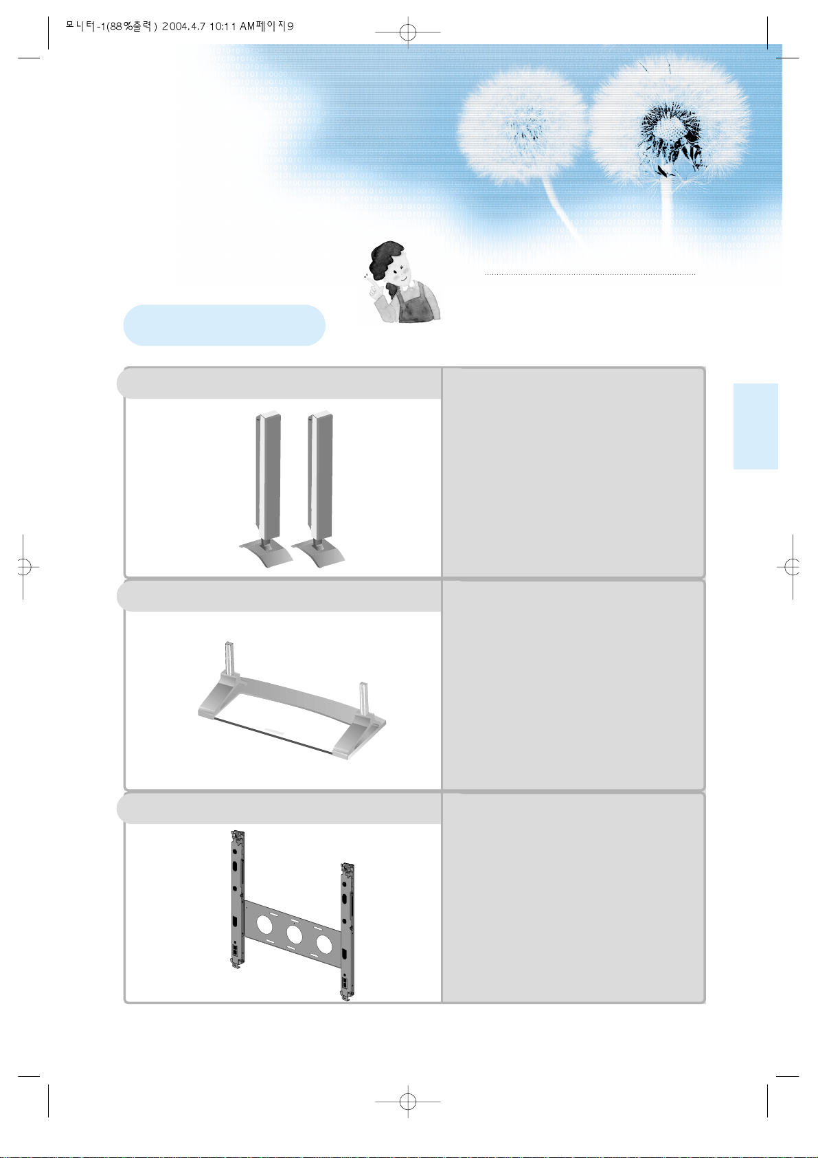
The following items are optional accessories.
Contact your local retailer for the purchase of
these optional accessories.
Optional Accessories
DSP/DP-SP20/SP21/SP22
-
Speaker Main Unit
Dimension : 100(W) x 628(H) 83(D)mm
-
Including Speaker Stand
Dimension : 170(W) x 729(H) x 194(D)mm
-
Audio Amplifier : 8W + 8W
-
Impedance : 8Ω
-
Weight : 7.5Kg
DSP/DP-ST20/ST21/ST22
-
Dimension : 667(W) x 238(H) x 320(D)mm
-
Weight : 7Kg
DSP/DP-HG22/HG20
•
Variable Angles : 0º, 10º, 15º, 20º
Speaker Main Unit
•
Dimension : 601(W) x 592(H) x 35(D)mm
Including Stand
•
Weight : 4.5Kg
Wall Mounting Unit
Table Top Stand
Speakers
Page 10
Page 11
11
4 • Safety Precautions
12 • Panel Controls
13 • Remote control
PREPARATION
BASICS
14 • Installation Instructions
15 • Connecting Speakers to PDP
CONNECTIONS
16 • Watching Digital Broadcasts
18 • Watching Cable Broadcasts
20 • Watching Satellite Broadcasts
22 • Watching a DVD Image
24 • Watching a VCR Image
26 • Watching a Camcorder/Game Console Image
28 • Connecting PC
APPLICATIONS
31 • Selecting Auto Picture Mode
34 •
Adjusting Screen Size
36 • Adjusting Screen Position and Size
38 • Enlarging Screen Size
40 • Watching a Still Image
41 • Adjusting Auto Sound Mode
42 • Customizing Sound Mode
44 • Selecting INPUT SIGNAL
46 • Checking the Current Input Signal
47 •
Selecting MENU Background Screen and Languages
49 • Setting Sleep Timer
MISC.
50 • Before Requesting Service
51 • SPECIFICATIONS
CONTENTS
Page 12
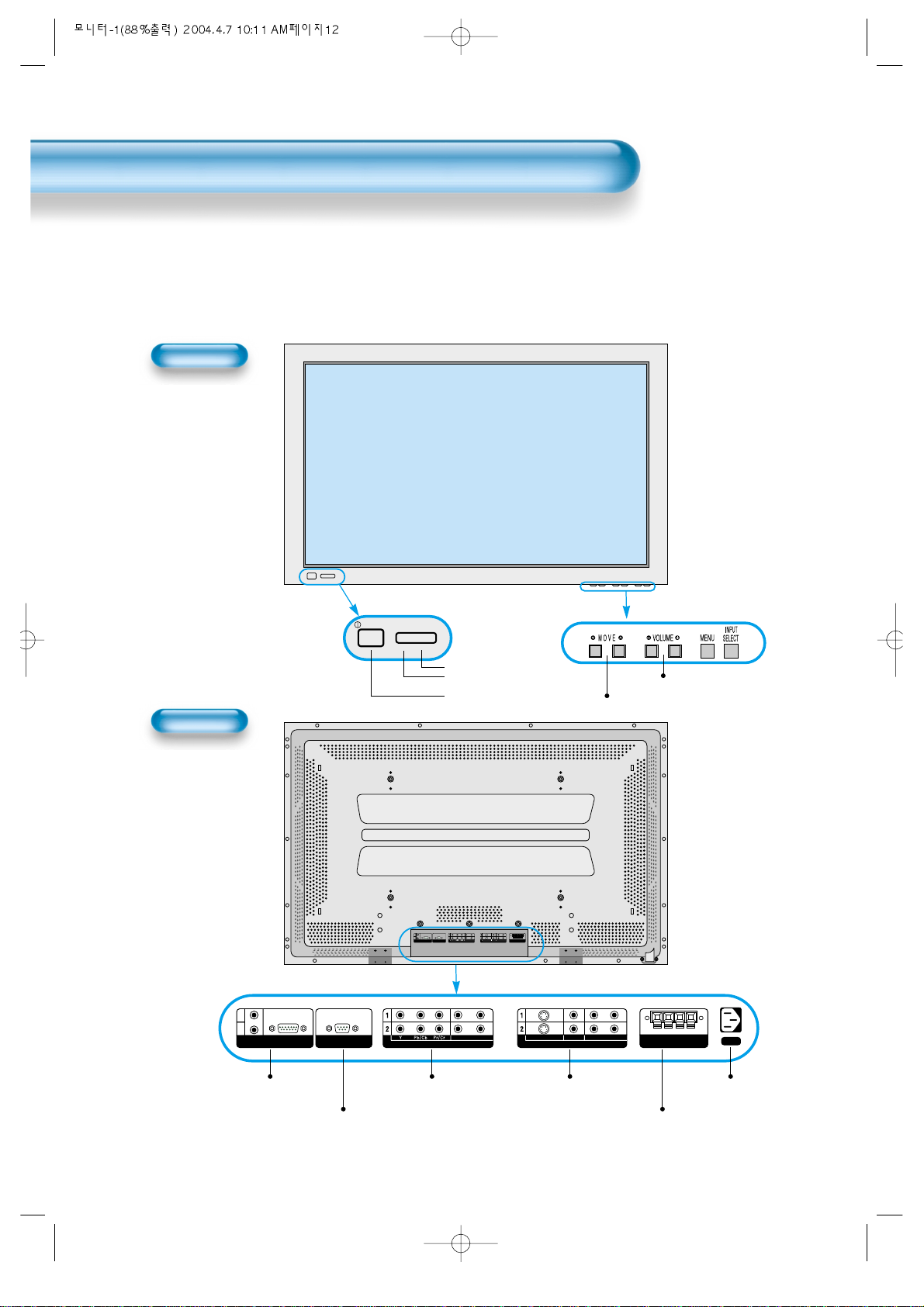
Panel Controls
12
Front Panel, Back Panel, Remote Control
*
Parts having same names in Plasma Display and Remote Control would function in exactly the
same way.
Front
Rear
PC INPUT RS-232C PORT
DTV/DVD INPUT VIDEO INPUT
SPEAKER(8 OHMS)
RL
L
R
AUDIO
L- AUDIO -R L- AUDIO -R
VIDEOS-VIDEO
PC INPUT RS-232C PORT
DTV/DVD INPUT VIDEO INPUT
SPEAKER(8 Ohms)
AC IN
RL
L
R
AUDIO
L- AUDIO -R L- AUDIO -R
VIDEOS-VIDEO
Power
•
Power control sensor
•
Power Standby: Red - Standby
Green - ON
Power button
Used when upgrading External Speaker
PC INPUT COMPONENT A/V jacks
(DTV/DVD INPUT jacks)
S-VIDEO, A/V INPUT,
Cable Receiver INPUT
jacks
Power
Select when adjusting volume or
select/adjust “MENU.”
Press when moving “MENU.”
STAND BY/OPERATE
Page 13
13
Remote Control
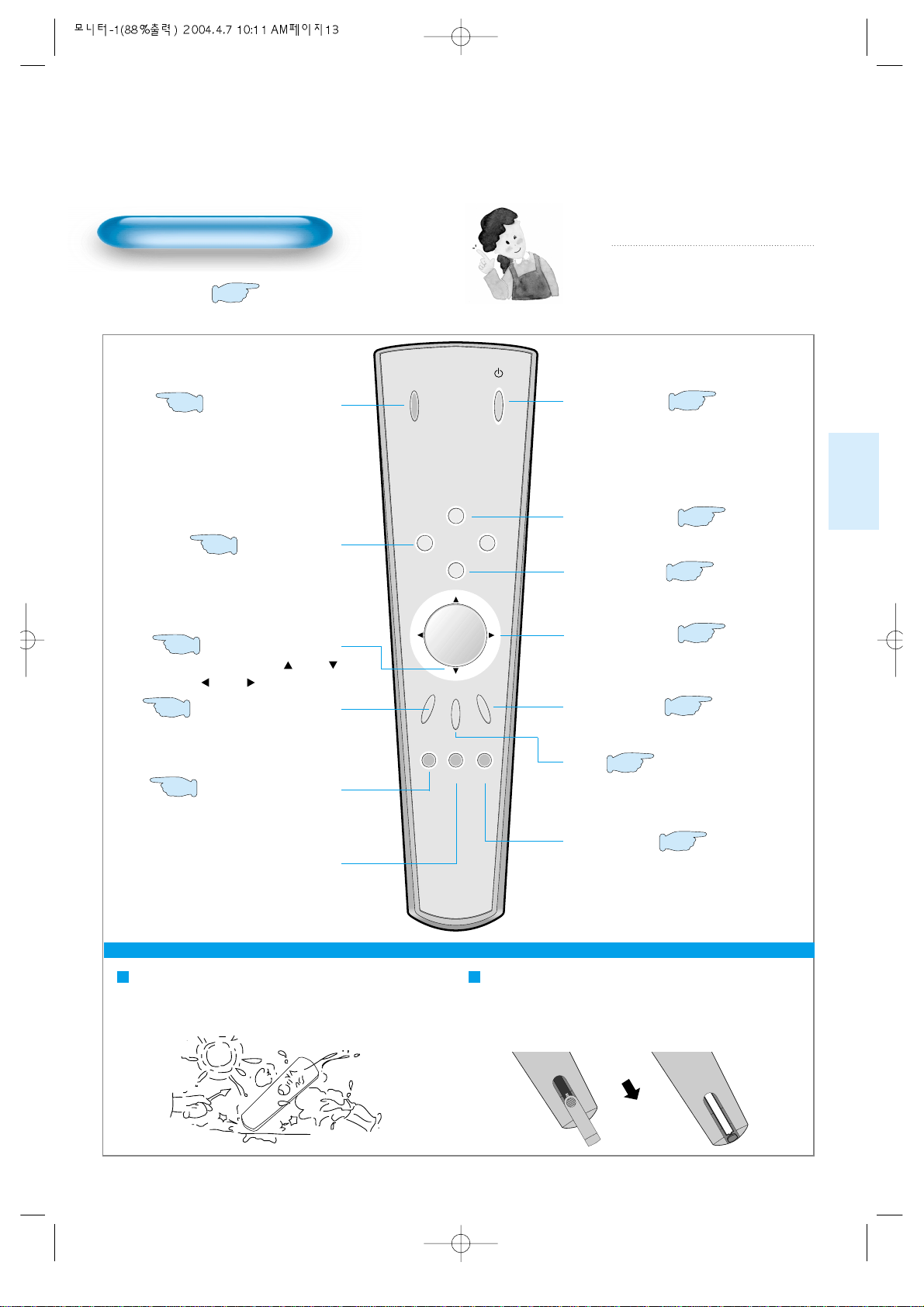
When Using Remote Control:
•
Be sure not to allow the Remote Control to be dropped or become wet.
•
Keep it away from hot or moist locations.
Installing the Batteries in your Remote Control:
•
To remove the cover, slide it outwards while pressing it down.
•
Place two batteries in the remote control by properly orienting
them, then close the cover.
INPUT
SELECT
POWER
DISPLAY
ZOOM
-
PICTURE
MODE
SCREEN
MODE
FREEZE
MUTESOUND
MODE
SLEEP
ZOOM+
MENU
VOL VOL
Input Select button
Used to select a desired input.
Every press of the button cycles
through the five different modes:
Video 1 --> Video 2 -->PC -->
Component 1 --> Component 2
Used to zoom the screen. To enlarge,
press the (+) button, and to return to
the previous condition, press the (-)
button. (ZOOM Mode: Zoom 0~20)
Select Menu by pressing (Up),
(Down), (Left), (Right) buttons.
Every press of the button cycles through
the four different modes: Normal -->
Dynamic --> Cinema --> User.
Every press of the button cycles through
the five different modes: Normal -->
Movie --> Music --> News --> User.
Mutes sound.
Pressing the Power button of the Monitor
allows the Display to be on standby. (Red
light is shown in the Remote Control
Sensor.) At this time, if you press the Power
button of the Remote Control, the Display is
turned ON (Green light in the Sensor).
Indicates the current state and resolution.
Used to display a desired menu.
Adjusts the volume.
Adjusts the size of the screen
(normal, 16:9, etc.)
Used to view a still picture during
the watching of moving images.
(Sound can be heard.)
Each time you press this button, a different
input mode appears.
The sequence is as follows:
15 Min. -->30 Min. -->60 Min. -->90 Min. -->120 Min. -->OFF
After the time is selected, it automatically
becomes a stand-by state.
44
32
Menu Select button
38
Screen Select button
31
Sound Mode button
41
Mute button
Aspect Ratio
34
Still
40
Sleep Timer
49
Power button
16
Display button
46
ZOOM button
Menu button
42
Volume button
32
Note
• Use two “AAA” batteries.
• Be sure to use replacement batteries of the
same type as the original ones.
• The life of a battery depends on how much
it has been used.
*
The number in
()
indicates the page in which
the function of each button is explained in detail.
Page 14
14
Installation Instructions
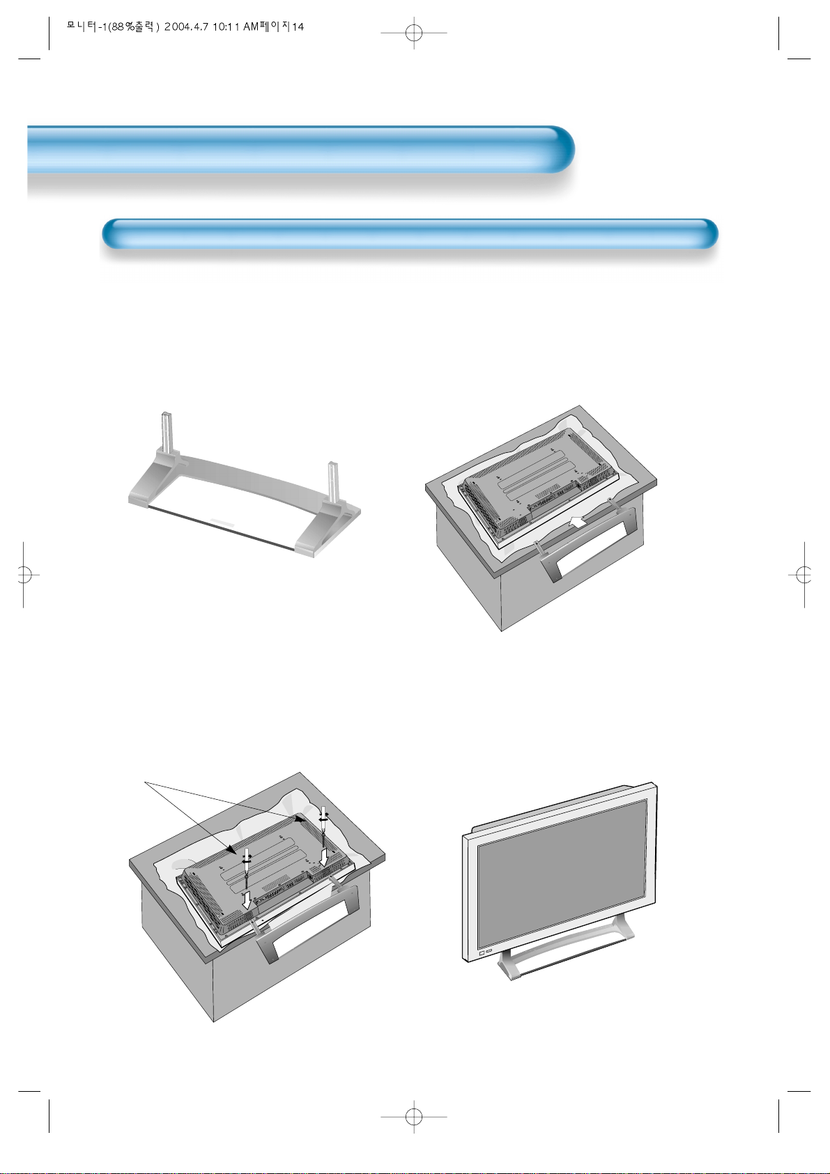
When Using the Stand
(Assembled Picture)
M5 SCREWS
Remove the STAND from the
package.
1
Engage the assembled stand
with 4 screws (M5) enclosed.
3
Smoothly fit the Stand to the
Plasma Display Panel
2
Erect the Display
4
*
When installing PDP Main Unit, be sure it is done by more than 2 professionals.
*
For detailed installation information, refer to the User’s Manual, “STAND”.
Page 15
15
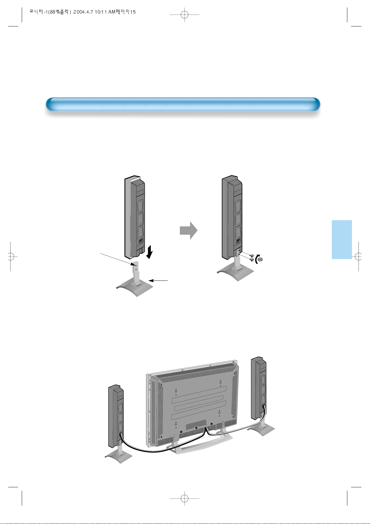
Connecting the Speaker to the Stand
1
Connecting the Speaker Cable
2
• By using a flat blade
screwdriver or coin,
fasten the special
screw securely.
Be sure to check if
there is a sponge
attached to the
surface on which the
speaker is contacted.
• Connect one set (two cables) of the cables to the terminals on the back of the
speaker in the way that red cable is for (+) terminal and black cable for (–)
terminal.
Stand
Connecting the Speaker to the PDP
Page 16
Watching Digital
Broadcasts
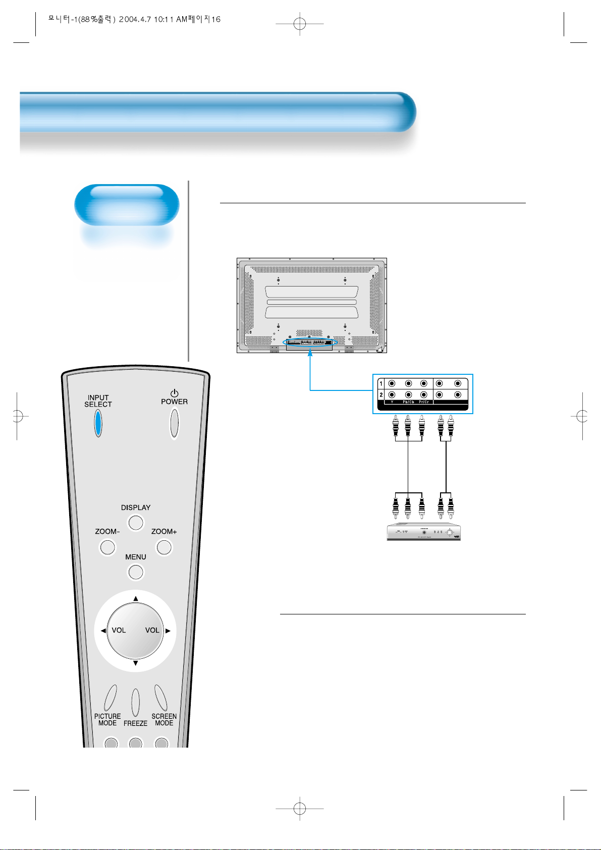
• To watch digital
broadcasts:
- Purchase a separate
digital Broadcasting
Receiver(SET-TOP
BOX)
- Connect the PDP to a
Cable Broadcasting
Receiver that is
provided by a
company which retransmits digital
broadcasts.
16
Watching Digital Broadcasts
Press the Power Buttons
• Press the Power buttons of the PDP and
the Receiver.
2
Connect a Digital Broadcasting Receiver to the
PDP
• Prepare A/V Cables supplied as shown on page 8.
• Connect the cables from the Digital TV Receiver output terminal to the
PDP(Component 1, 2) input terminal.
• When connecting the cables, be sure to match the cable colors correctly.
1
DTV/DVD INPUT
L- AUDIO -R
PC INPUT RS-232C PORT
DTV/DVD INPUT VIDEO INPUT
SPEAKER(8 OHMS)
RL
L
R
AUDIO
L- AUDIO -R L- AUDIO -R
VIDEOS-VIDEO
Video
Digital Broadcasting Receiver
(Set-T op Box)
Audio
Page 17
17
Input Select
INPUT
SELECT
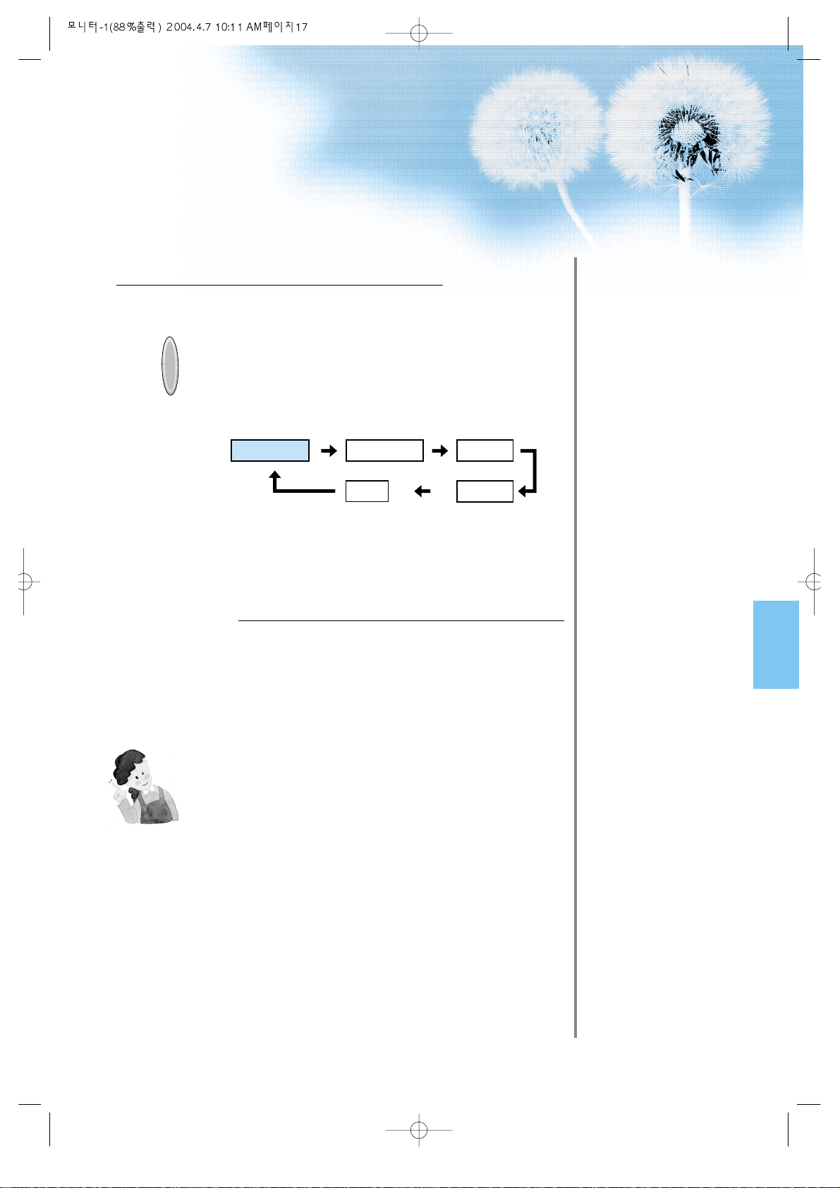
• Select [Component 1 or Component 2] by
pressing the INPUT SELECT button of the
Remote Control or the PDP unit.
• Each time you press the INPUT SELECT
button, different input modes appear. The
sequence is as follows: Component 1 -->
Component 2 --> Video 1 --> Video 2 -->
PC.
Select a Desired Channel and Function
• Select a desired channel and function by
using the Remote Control of the Digital
Broadcasting Receiver.
3
4
NOTES:
1) You can select INPUT SELECT while you are using OSD(Menu).
Sequence: [Menu] --> [Input] -->[Component 1 or 2 (DTV/DVD)]
2) Digital Broadcasting signals available: 1080i(60Hz), 720p(60Hz),
480p(60Hz)
3) Antenna Connection:
Apartment : Check if community antenna receives digital broadcasts.
Private Houses: Set the indoor/outdoor UHF antenna to the direction
of the digital broadcasting transmitting company.
4) For detailed connection method, refer to the Owner’s Manual of Digital
Broadcasting Receiver.
5) What is a component? : Signal with which brightness and colour
signals are separated, producing a sharp screen.
6) If the Digital Broadcasting Receiver has PC Output terminal
(D-sub15pin), connect to ‘PC INPUT’ at the back panel of the PDP.
When watching the PDP by PC Input, some undesired signals may be
seen at the top and bottom area of the screen. In this case, select
[Menu] --> [Screen] --> [Vertical Size] to adjust.
Component1
PC
Component2
Video1
Video2
Page 18
Watching Cable
Broadcasts
• To watch cable
broadcasts,
subscribe to your
local Cable TV
Broadcasting, and
then, connect the
digital set-top box for
cable TV to the PDP
as shown below.
Watching Cable Broadcasts
18
Press the Power Buttons
• T urn the PDP and the Receiver ON.
2
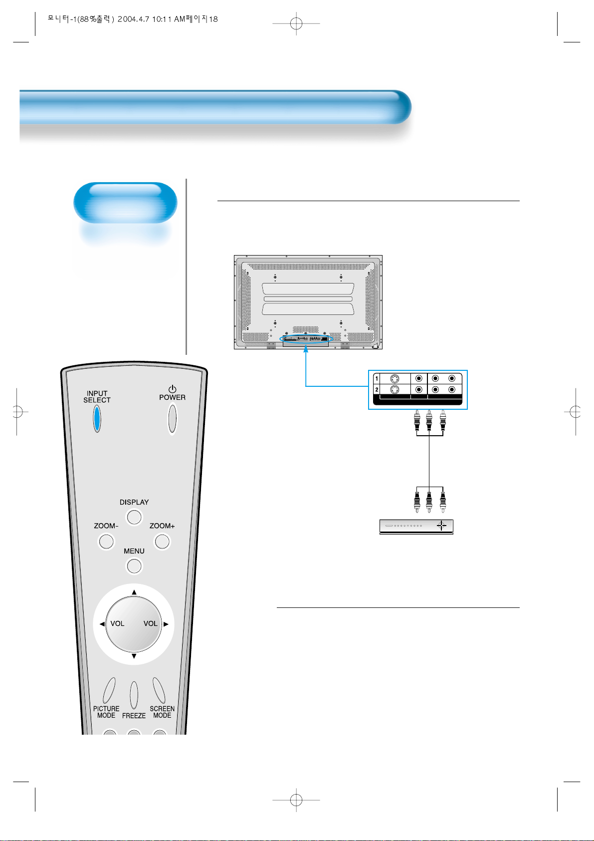
Connect a CABLE Broadcasting Receiver to the
PDP.
• Prepare the A/V connecting cable as shown on page 8.
• Connect the receiver(Output) to PDP(V ideo Input) as shown below .
• When connecting to an external AV source, be sure to match the colors.
1
VIDEO INPUT
L- AUDIO -R
VIDEOS-VIDEO
PC INPUT RS-232C PORT
DTV/DVD INPUT VIDEO INPUT
SPEAKER(8 OHMS)
RL
L
R
AUDIO
L- AUDIO -R L- AUDIO -R
VIDEOS-VIDEO
Video/Audio
Cable Broadcasting Receiver
Page 19
19
Input Select
INPUT
SELECT
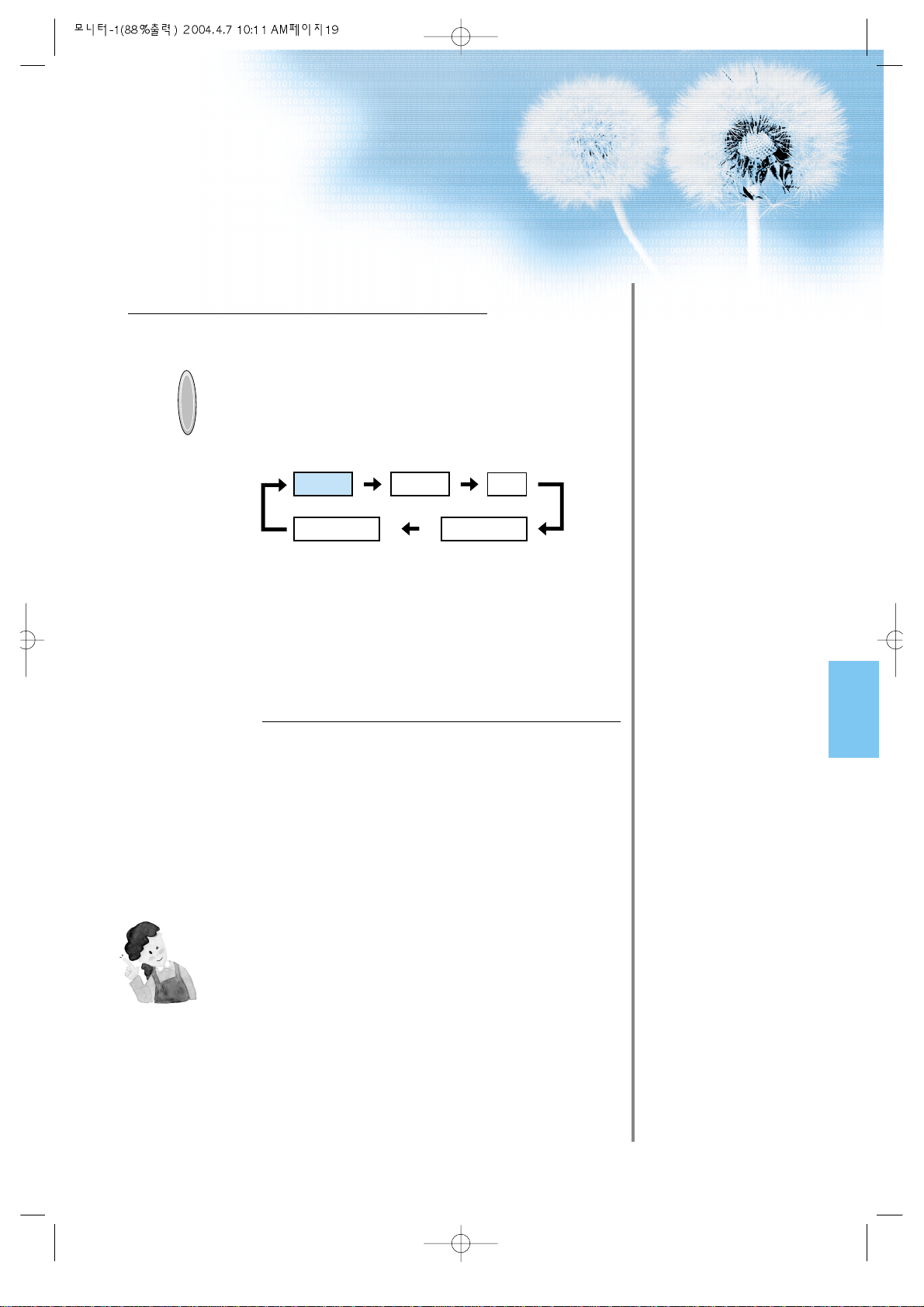
• Select [Video 1 or Video 2] by pressing
the INPUT SELECT button of the Remote
Control or the PDP unit.
• Each time you press the INPUT SELECT
button, different input modes appear. The
sequence is as follows: Video 1 --> Video
2 --> PC -->Component 1 -->Component 2.
Select a Desired Channel and Function
• Select a desired channel and function by
using the Remote Control of the Cable
Broadcasting Receiver.
3
4
NOTES:
*
If your local cable company re-transmits digital broadcasts, you
may watch normal broadcasts and digital broadcasts
simultaneously. For detailed information, refer to your local
satellite company.
Video1 Video2 PC
Component1Component2
Page 20
Watching Satellite
Broadcasts
• To watch satellite
broadcasting,
subscribe to a Digital
Satellite
Broadcasting, then
connect the digital
set-top box for
satellite
broadcasting to the
PDP as shown
below.
Watching Satellite Broadcasts
20
Press the Power Buttons
• T urn the PDP and the Receiver ON.
2
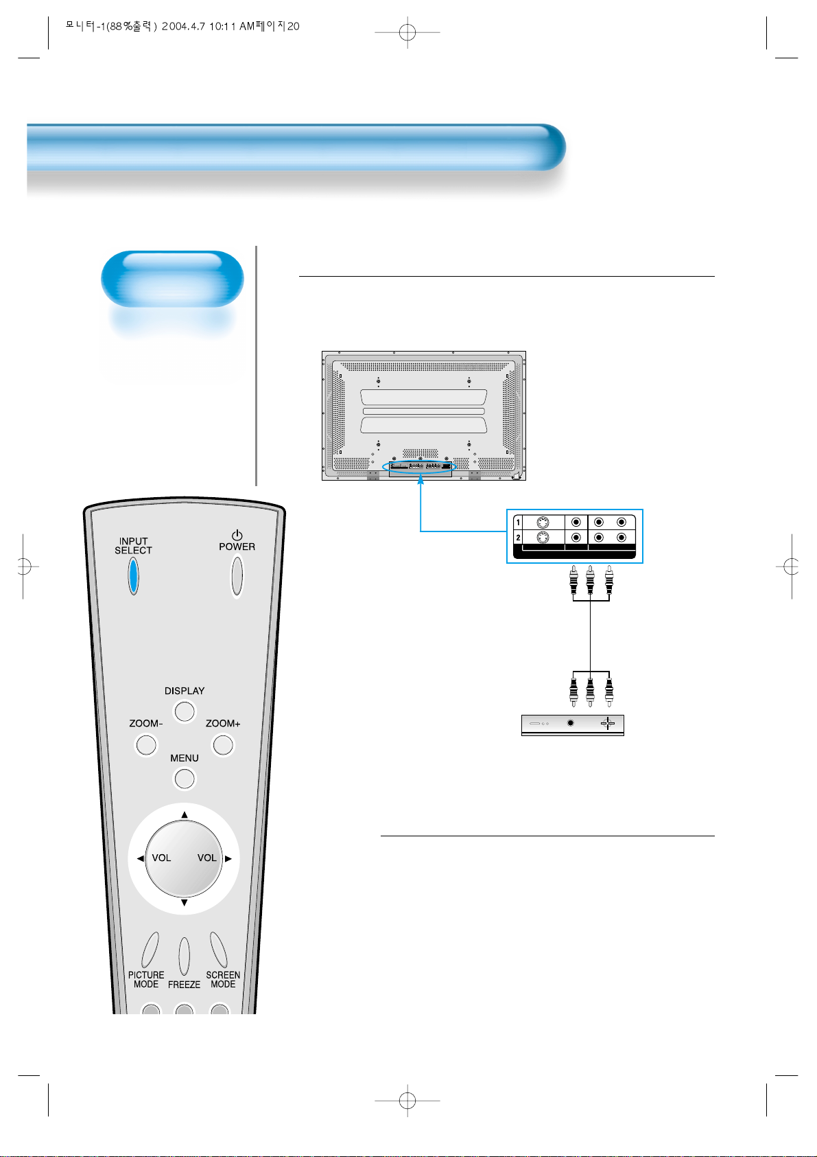
Connect a Satellite Broadcasting Receiver to
the PDP.
• Prepare the A/V connecting cable as shown on page 8.
• Connect the receiver(Output) to PDP(V ideo Input) as shown below .
• When connecting to an external AV source, be sure to match the colours.
1
VIDEO INPUT
L- AUDIO -R
VIDEOS-VIDEO
PC INPUT RS-232C PORT
DTV/DVD INPUT VIDEO INPUT
SPEAKER(8 OHMS)
RL
L
R
AUDIO
L- AUDIO -R L- AUDIO -R
VIDEOS-VIDEO
Video/Audio
Satellite Broadcasting Receiver
Page 21
21
Input Select
INPUT
SELECT
• Select [Video 1 or Video 2] by pressing
the INPUT SELECT button of the
Remote Control or PDP unit.
• Each time you press INPUT SELECT
button, a different input mode appears.
The sequence is as follows: Video 1 -->
Video 2 --> PC -->Component 1 -->
Component 2.
Select a Desired Channel and Function
• Select a desired channel and function by
using the Remote Control of the Satellite
Broadcasting Receiver.
3
4
NOTES:
*
Picture quality of the Digital Satellite broadcasts is SD grade,
and its aspect ratio is 16:9.
Video1 Video2 PC
Component1Component2
Page 22

Watching a DVD
Image
• Component Input is
set to 480i and 480p
mode.
• Connect the cable
from the DVD Video
Output (Y, Pb/Cb,
Pr/Cr) to the
Component Input at
the back of PDP, and
connect the cable
from DVD Audio
output (Left, Right)
to the Audio Input at
the back of PDP.
Watching a DVD Image
22
Press the Power Buttons
• T urn the PDP and the DVD ON.
2
Connect a DVD Player to the PDP.
• Prepare the AV cable as shown on page 8.
• Connect the DVD(Output) to the PDP(Component or V ideo Input) as shown below .
• When connecting to an external AV source, match the colors.
1
DTV/DVD INPUT VIDEO INPUT
L- AUDIO -R L- AUDIO -R
VIDEOS-VIDEO
PC INPUT RS-232C PORT
DTV/DVD INPUT VIDEO INPUT
SPEAKER(8 OHMS)
RL
L
R
AUDIO
L- AUDIO -R L- AUDIO -R
VIDEOS-VIDEO
Video
DVD DVD
Video/
Audio
S-
Video
Audio
Page 23
23
Input Select
INPUT
SELECT
• Select [Component 1 or Component 2,
Video1, Video2] by pressing the INPUT
SELECT button of the Remote Control or
the PDP unit.
• Each time you press the INPUT SELECT
button, a different input mode appears. The
sequence is as follows: Component 1 -->
Component 2 --> Video 1 --> Video 2 -->
PC.
Select a Desired Title and Function
• Select a desired title and function by
using the Remote Control of the DVD.
3
4
NOTES:
1) Y/Cb/Cr, which stands for DVD Player’s Output Terminal, can
also be written as Y/B-Y/R-Y, Y/Pb/Pr depending on the kinds
of DVD devices.
2) The way of connecting the DVD to the PDP is as follows:
Y <---> Y Cb <---> Pb, B-Y, Cr <--->Pr, R-Y
3)
The DVD output can be made by Video, S-Video and/or
Component Video depending on the DVD devices. There are
various output modes, so be sure to check when you purchase it.
4) When connecting S-Video and normal Video simultaneously,
only S-Video will be displayed on the screen.
Component1
PC
Component2
Video1
Video2
Page 24
Watching a
VCR Image
• Video can use either
the normal video
terminal or the
S-video terminal.
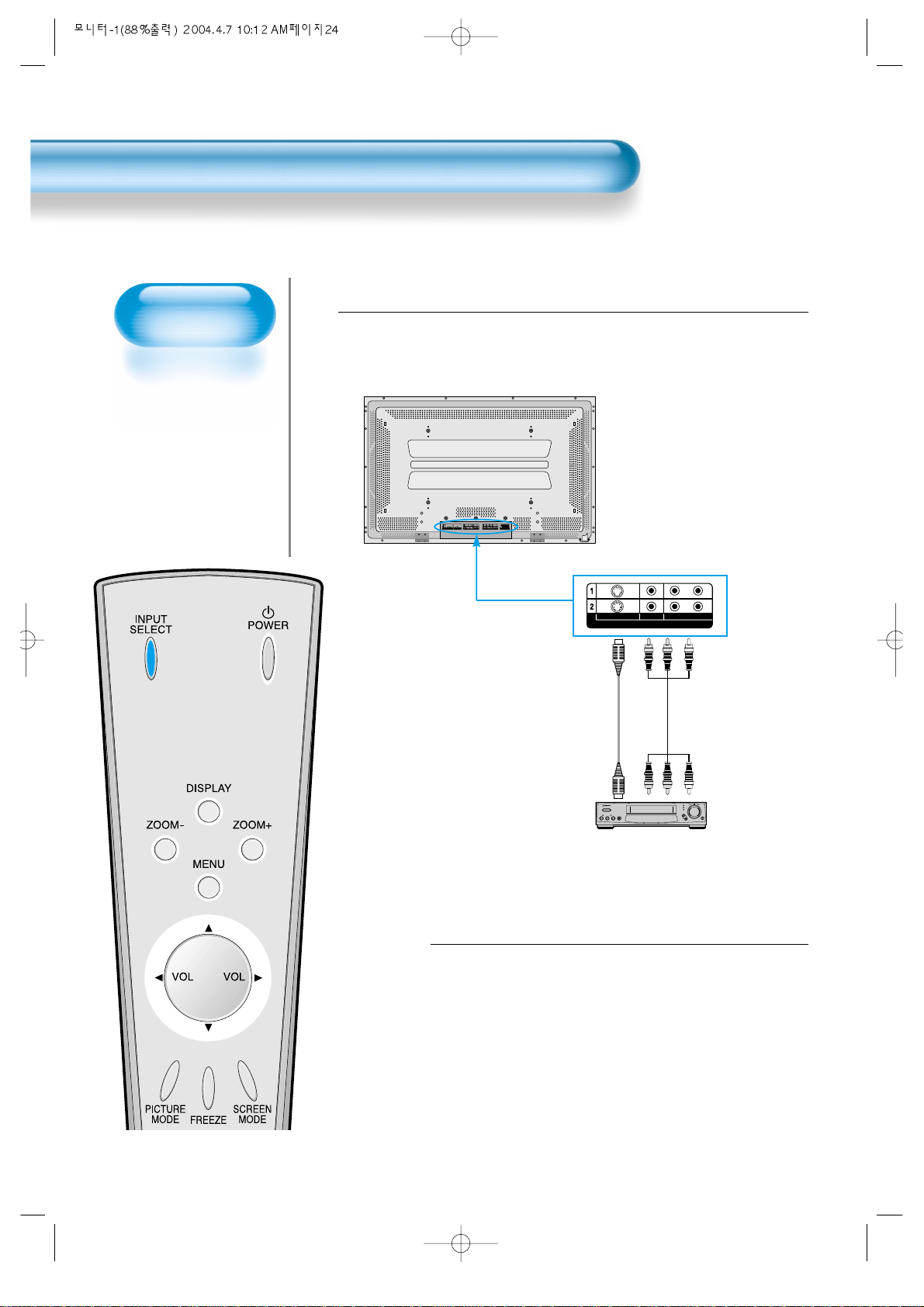
Watching a VCR Image
24
Press the Power Buttons
• T urn the PDP and the VCR ON.
2
Connect a VCR to the PDP.
• Prepare the AV cable as shown on page 8.
• Connect the Video(Output) to PDP(Video Input) as shown below.
• When connecting to an external AV source, match the colours.
1
VIDEO INPUT
L- AUDIO -R
VIDEOS-VIDEO
PC INPUT RS-232C PORT
DTV/DVD INPUT VIDEO INPUT
SPEAKER(8 OHMS)
RL
L
R
AUDIO
L- AUDIO -R L- AUDIO -R
VIDEOS-VIDEO
S-Video
VCR
Video/Audio
Page 25
25
Input Select
INPUT
SELECT
• Select [Video 1 or Video 2] by
pressing the INPUT SELECT button
of Remote Control or PDP unit.
• Each time you press the INPUT
SELECT button, a different input
mode appears. The sequence is as
follows: Video 1 -->Video 2 -->PC -->
Component 1 -->Component 2.
Select a Desired Title and Function
• Select a desired title and function by
using the Remote Control of the
VCR.
3
4
NOTES:
1) When connecting a Video, the S-Video terminal provides a
better image than the normal Video terminal.
2) When connecting to the normal video terminal, connect 3 color
AV cables (video, left audio, right audio) to the PDP; for the SVideo terminal, connect the Audio terminal (Left, Right) in the
same way, and connect the Video terminal by the S-Video
cable (sold separately).
3) When connecting the normal Video terminal and the S-Video
simultaneously, the S-Video terminal is selected. This can be
checked by the [Display] button of the Remote Control.
Video1 Video2 PC
Component1Component2
Page 26
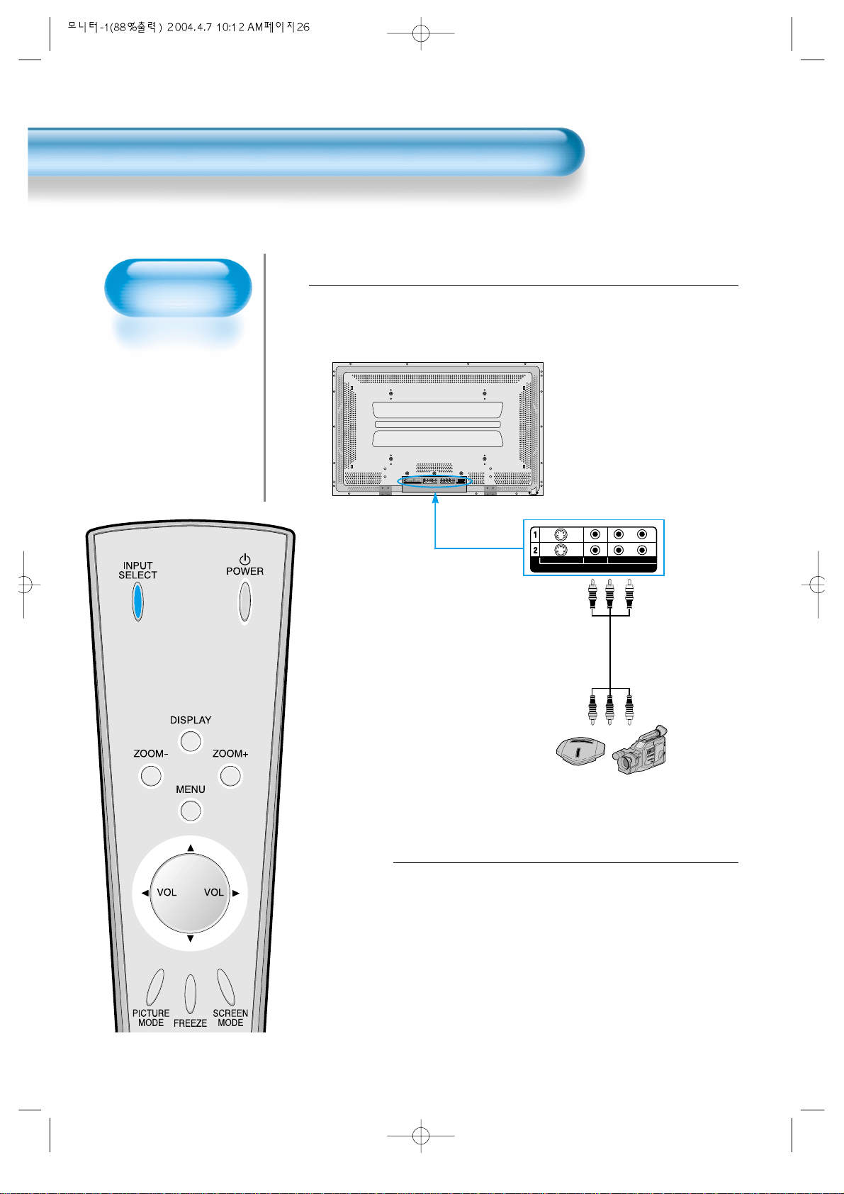
Watching a
Camcorder/Game
Console Image
• Enjoy images
recorded by
camcorder or the
game console after
connecting to the
PDP.
W atching a Camcorder/Game Console Image
26
Press the Power Buttons
• Turn the PDP and the
Camcorder/Game Console ON.
2
Connect a Camcorder/Game Console to the
PDP.
• Prepare the AV cable as shown on page 8.
• Connect the Video(Output) to the PDP(Video Input) as shown below.
• When connecting to an external AV source, match the colors.
1
VIDEO INPUT
L- AUDIO -R
VIDEOS-VIDEO
PC INPUT RS-232C PORT
DTV/DVD INPUT VIDEO INPUT
SPEAKER(8 OHMS)
RL
L
R
AUDIO
L- AUDIO -R L- AUDIO -R
VIDEOS-VIDEO
Video/Audio
Game Console/Camcorder
Page 27
27
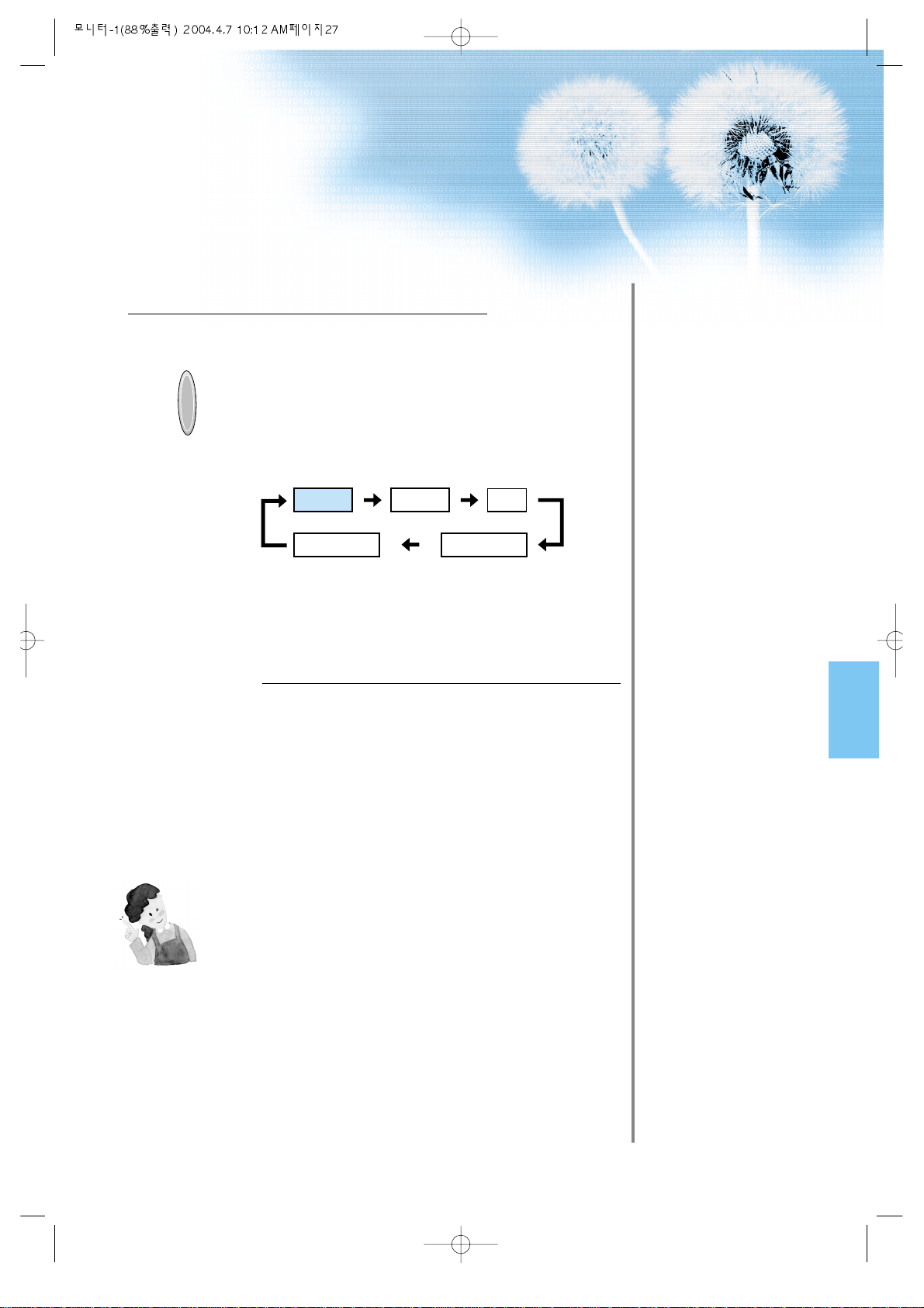
Input Select
INPUT
SELECT
• Select [Video 1 or Video 2] by
pressing the INPUT SELECT button
of the Remote Control or the PDP
unit.
• Each time you press the INPUT
SELECT button, a different input
mode appears. The sequence is as
follows: Video 1 -->Video 2 -->PC -->
Component 1 -->Component 2.
Select a Desired Title and Function
• Select a desired title and function by
using the Remote Control of the VCR.
3
4
NOTES:
1) When connecting a Video, the S-Video terminal provides a
better image than the normal Video terminal.
2) When connecting to the normal video terminal, connect 3 color
AV cables (video, left audio, right audio) to the PDP; for the SVideo terminal, connect the Audio terminal (Left, Right) in the
same way, and connect the Video terminal by S-Video
cable(sold separately).
Video1 Video2 PC
Component1Component2
Page 28
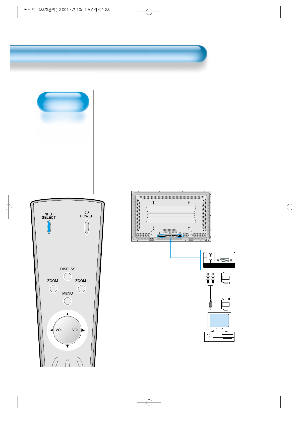
Connecting PC
• PLASMA supports
resolution of VGA,
SVGA, XGA, SXGA,
UXGA.
• Before connecting a
PC to the PDP, be
sure to adjust the
resolution of PC.
• This product is not
supported by Plug
and Play, so select
Standard Monitor
when setting PC
monitor.
Connecting PC
28
Connect the PC to the PDP.
• Prepare the PC cable (D-sub 15pin) and
the PC audio cable(Sold seperately).
• Connect the PC(Output) to the
PDP(Input) as shown below.
2
Before connecting to the PDP, set the
resolution of the PC.
• Go to SETUP-CONTROL PANEL-DISPLAY PROPERTIES in Window
Screen.
• Choose the SETTINGS tab in the DISPLAY Menu.
• In the SETTINGS Menu, select 640x480 or 800x600.
1
PC INPUT
L
R
AUDIO
PC INPUT RS-232C PORT
DTV/DVD INPUT VIDEO INPUT
SPEAKER(8 OHMS)
RL
L
R
AUDIO
L- AUDIO -R L- AUDIO -R
VIDEOS-VIDEO
15 PIN D-sub
PC
Audio
Page 29
29
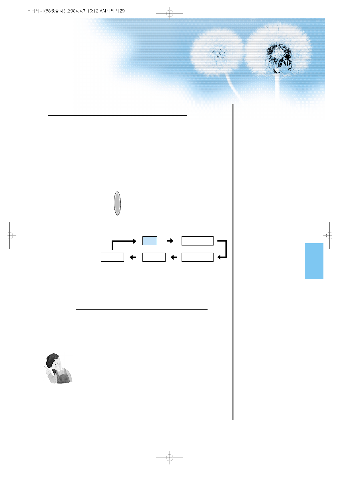
Input Select
INPUT
SELECT
• Select [PC] by pressing the INPUT
SELECT button of the Remote Control or
PDP unit.
• Each time you press the INPUT SELECT
button, a different input mode appears. The
sequence is as follows:
PC --> Component 1 --> Component 2 -->
Video 1 - - >Video 2.
Enjoy Dynamic Ultra Screen Monitor by
Using PC’s Keyboard or Mouse.
4
5
Press the Power button.
• Turn on the PDP and the PC.
3
NOTES:
1) The resolution of the PC monitor is best at 640 x 480 (VGA).
2) If there is a [Vertical Frequency]setting menu in the [Display]
Menu of the PC, adjust the frequency to 60Hz.
3) If the PC resolution is too high, it may be hard to read letters.
Select a suitable resolution.
PC
Component1
Component2Video1Video2
Page 30
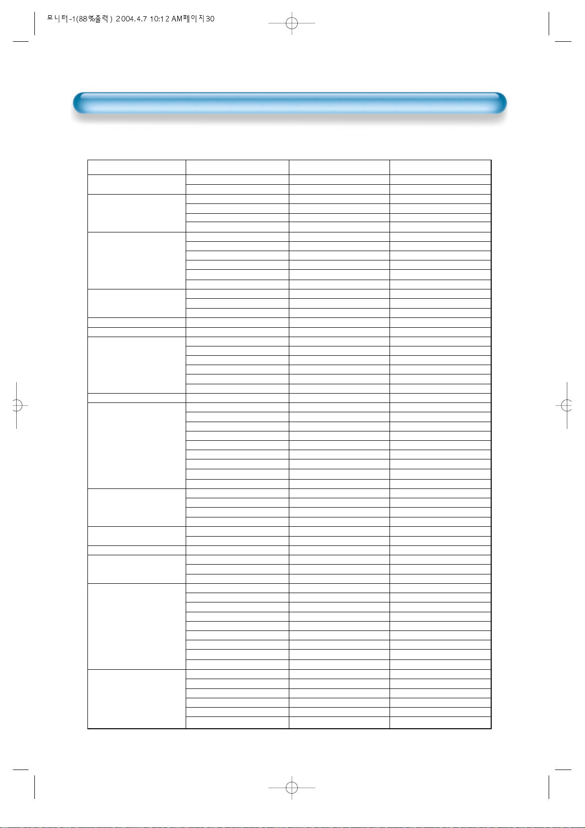
PC Input Resolution Available in PDP
Resolution
Horizontal Frequency(KHz) Vertical Frequency(Hz) Remark
30
31.469
37.861
24.823
30.48
31.469
37.861
31.469
35
37.861
37.5
39.375
43.269
31.47
31.469
37.927
31.54
15.63
35.156
35.16
37.879
48.077
46.875
53.674
49.726
48.193(48.077)
48.363
53.95
56.476
60.241
60.023
68.677
80.66
70.84
54
63.851
67.5
77.094
61.796
71.713
45
60
75
85.938
46.433
63.981
70.66
74.88
78.125
78.855
79.976
81.13
91.416
62.5
75
81.25
87.5
93.75
100
640x350
640x400
640x480
720x400
720x480
720x576
800x600
832x624
1024x768
1152x864
1152x900
1280x720
1280x960
1280x1024
1600x1200
70.1
85.1
56.4
60.0
70.1
85.1
59.9
66.7
72.8
75.0
75.0
85.0
60.1
70.1
85.1
60.0
25.0
56.3
57.2
60.3
72.2
75.0
85.1
74.0
59.3(59.8)
60.0
66.1
70.1
74.9(74.6)
75.0
85.0
100.0
84.0
60.0
70.0
75.0
85.0
66.0
76.0
60.0
60.0
75.0
85.0
43.4
60.0
66.5
70.0
72.0
74.0
75.0
76.1
85.0
48.0
60.0
65.0
70.0
75.0
80.0
IBM
VESA
NEC
PGA
IBM (DOS)
VESA
DOS
Macintosh
VESA
VESA
IBM
VESA
VGA
IBM
VESA
480P
PAL
VES
VESA
VESA
VESA
VESA
VESA
Macintosh
Macintosh (OAK)
VESA
XGA
HP & VESA
Macintosh
VESA
VESA
Fujitsu
SUN
VAX
VESA
VESA
VESA
SUN
SUN
720P
VESA
VESA
VESA
VESA
VESA
VAX
NEC
HP & HITA
Sony & NEC
VESA
SUN
VESA
VESA
VESA
VESA
VESA
VESA
VESA
• According to the kind of graphic card, if there is no picture from pc input you may encounter problems
like line noises in the picture. If these problems occur, consult a graphic card company.
Page 31
Selecting Auto
Picture Mode
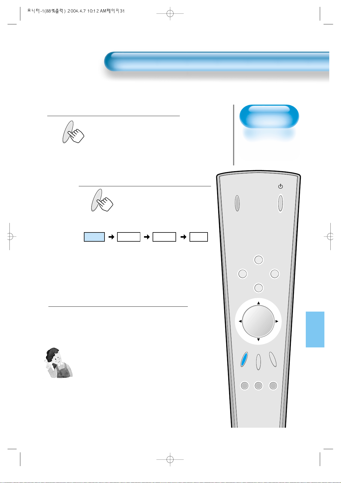
• Select the Picture modes
that are automatically set
depending on the kinds
of pictures, and enjoy
them.
Selecting Picture Mode
PICTURE
MODE
• Press the [PICTURE MODE] on the
Remote Control.
• Pressing the [PICTURE MODE] first time
will display the current PICTURE MODE.
Each Press of the Button Will Select
One of Four Picture Modes.
• Each time you press the button, a
different Picture mode appears. The
sequence used is as follows:
* Normal : For a highly defined image in a normally bright
room
* Dynamic: For a clear-cut image emphasizing high contrast
for sports viewing
* Cinema: For a movie
* User: Allows the user to customize settings as desired.
Menu on the Screen Will Disappear .
• After selecting a desired Picture mode, the
menu on the screen will disappear.
• Normal, Dynamic, and Cinema Modes are
factory preset values.
If you want to customize the Picture modes,
refer to the following page.
3
1
2
Selecting Auto Picture Mode
31
NOTES:
* Normal, Dynamic, and Cinema Modes are factory preset values.
* When adjusting sub-menus while you are in Normal, Dynamic,
and Cinema Modes, the Picture Mode will be automatically
converted to User Mode, and the adjustments will be made.
* Pressing of the [INITIALIZATION] button in the [Utility] Menu will
allow for the Brightness, Contrast, etc. to return to the factory
preset values.
* The SHARP Menu adjusts the picture sharpness.
* Adjusting the Colour Temperature makes the mood warm or cold.
PICTURE
MODE
INPUT
SELECT
POWER
DISPLAY
ZOOM
-
PICTURE
MODE
SCREEN
MODE
FREEZE
MUTESOUND
MODE
SLEEP
ZOOM+
MENU
VOL VOL
Normal Dynamic
Cinema User
Page 32
Customizing
Picture
• You can adjust the
color tone and
brightness to your
preference.
Customizing Picture
32
INPUT
SELECT
POWER
DISPLAY
ZOOM
-
PICTURE
MODE
SCREEN
MODE
FREEZE
MUTESOUND
MODE
SLEEP
ZOOM+
MENU
VOL VOL
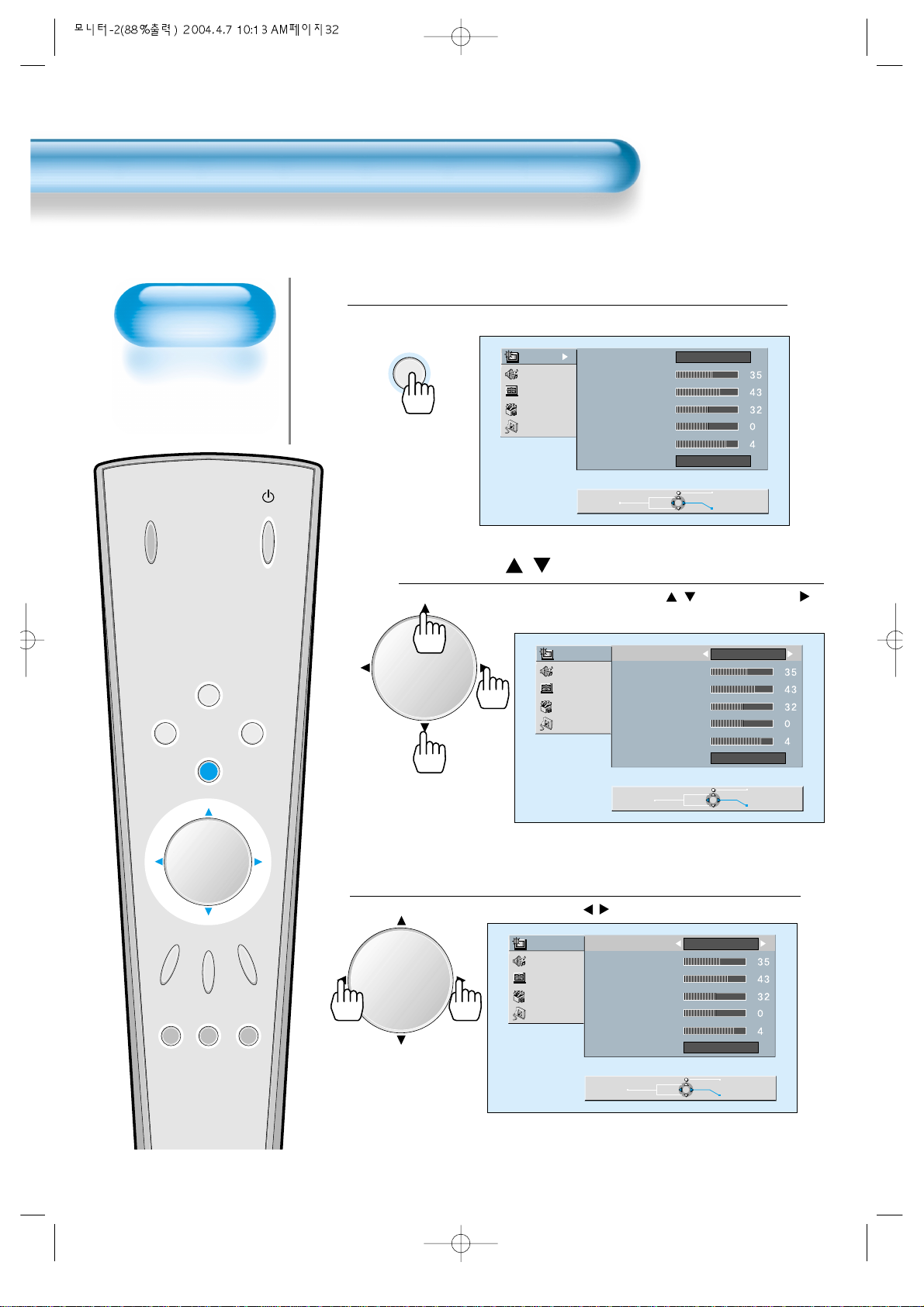
Press the / Button.
• After selecting [Picture] by the / buttons, press the
button that will display the following.
Select the Custom Mode.
• Select [User] by the / buttons.
3
Press the MENU Button.
• The MENU shown below will display on the screen.
1
2
MENU
VOLVOL
Picture
Sound
Screen
Utility
Input
Picture
Sound
Screen
Utility
Input
Mode
Brightness
Contrast
Color
Tint
Sharpness
Color T emp.
Move
Mode
Brightness
Contrast
Color
Tint
Sharpness
Color T emp.
Normal
Normal
Previous
Select
Normal
Normal
VOLVOL
Picture
Sound
Screen
Utility
Input
Move
Mode
Brightness
Contrast
Color
Tint
Sharpness
Color T emp.
Move
User
Normal
Previous
Adjust
Previous
Adjust
Page 33
Select User Mode Adjustments
Picture Condition Adjustments
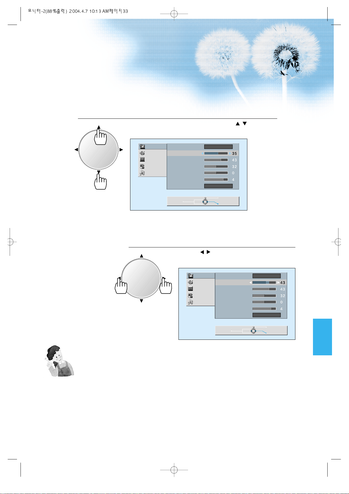
• Press the / buttons to adjust the picture to your
preference.
4
5
33
• While you are in [Picture Mode – User], press the / buttons to
select a specific item for adjustment.
NOTES:
* While you are in the PC INPUT mode, you can only adjust
brightness, contrast, sharpness and colour temperature.
* When you adjust Brightness, Contrast, Colour, Tilt in the DTV or
the PC mode, the picture is adjusted finely.
* The adjusted Values are memoried in each mode seperately.
VOLVOL
VOLVOL
Picture
Sound
Screen
Utility
Input
Mode
Brightness
Contrast
Color
Tint
Sharpness
Color T emp.
Move
User
Normal
Previous
Adjust
Picture
Sound
Screen
Utility
Input
Mode
Brightness
Contrast
Color
Tint
Sharpness
Color T emp.
User
Normal
Move
Previous
Adjust
Page 34
Adjusting
Screen Size
• You can adjust
screen size or
aspect ratio as
desired.
Adjusting Screen Size
34
INPUT
SELECT
POWER
DISPLAY
ZOOM
-
PICTURE
MODE
SCREEN
MODE
FREEZE
MUTESOUND
MODE
SLEEP
ZOOM+
MENU
VOL VOL
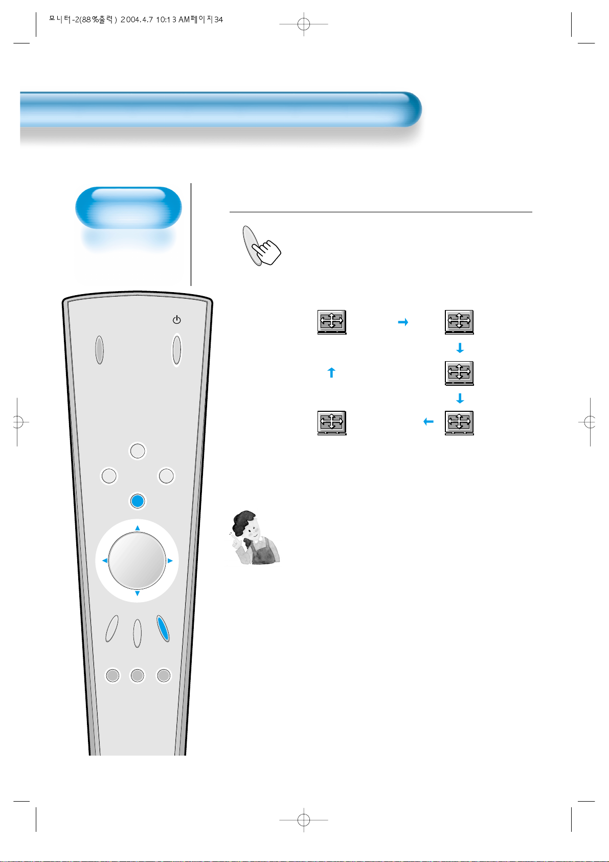
Press the SCREEN MODE Button.
• Each time you press the SCREEN MODE button on the
Remote Control, a different SCREEN MODE appears. The
sequence used is as follows:
• The MENU shown below will display on the screen.
1
SCREEN
MODE
Enlarge LBS
Normal
16:9
Panorama
Enlarge LB
NOTES:
1) When the INPUT SIGNAL is DTV [in COMPONENT 1 or
COMPONENT 2], only the aspect ratios of 16:9 and
4:3(Normal) will be applied by Input signal.
If input signal is 16:9, PDP displays in 16:9 mode.
2) The digital broadcasting (720p, 1080i) is fixed at the aspect
ratio of 16:9.
3) Displaying a picture in a normal mode (4:3) for a long time
may cause phosphor of the PDP to be burned. So avoid
displaying a picture in a normal mode for a long time.
4) 16:9 : Theater-like 16:9 picture formats
Panorama : 16:9 picture formats with panorama effect
Normal : Displays pictures of normal size (i.e., a 4:3
aspect ratio)
Enlarge LB : Enlarges the picture so as to fill the entire
screen area.
Enlarge LBS: Enlarges the screen, and shifts up so as to see
the subtitles in case you are watching a picture
with subtitles.
Page 35
35
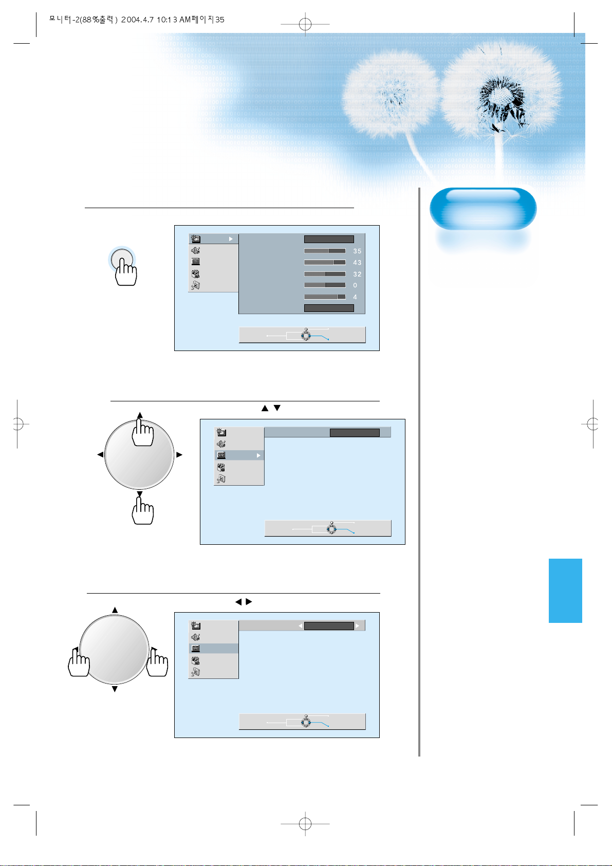
Press the MENU Button.
• Press the [MENU] button on the Remote Control.
Select “Screen”.
• Press the Channel / buttons to select “Screen.”
Select the Screen Size.
• Press the V olume / buttons to select “Screen Size”.
3
1
2
Adjusting from
MENU Screen
MENU
Picture
Sound
Screen
Utility
Input
Mode
Brightness
Contrast
Color
Tint
Sharpness
Color T emp.
Normal
Normal
VOLVOL
VOLVOL
Move
Picture
Sound
Screen
Utility
Input
Picture
Sound
Screen
Utility
Input
Mode Normal
Move
Mode Enlarge LB
Previous
Select
Previous
Select
Move
Previous
Adjust
Page 36
Adjusting Screen
Position and Size
• You can adjust the
screen position and
size as desired.
• This function is only
used when adjusting
the screen position
and size on the PDP
monitor by using the
PC input signal.
INPUT
SELECT
POWER
DISPLAY
ZOOM
-
PICTURE
MODE
SCREEN
MODE
FREEZE
ZOOM+
MENU
VOL VOL
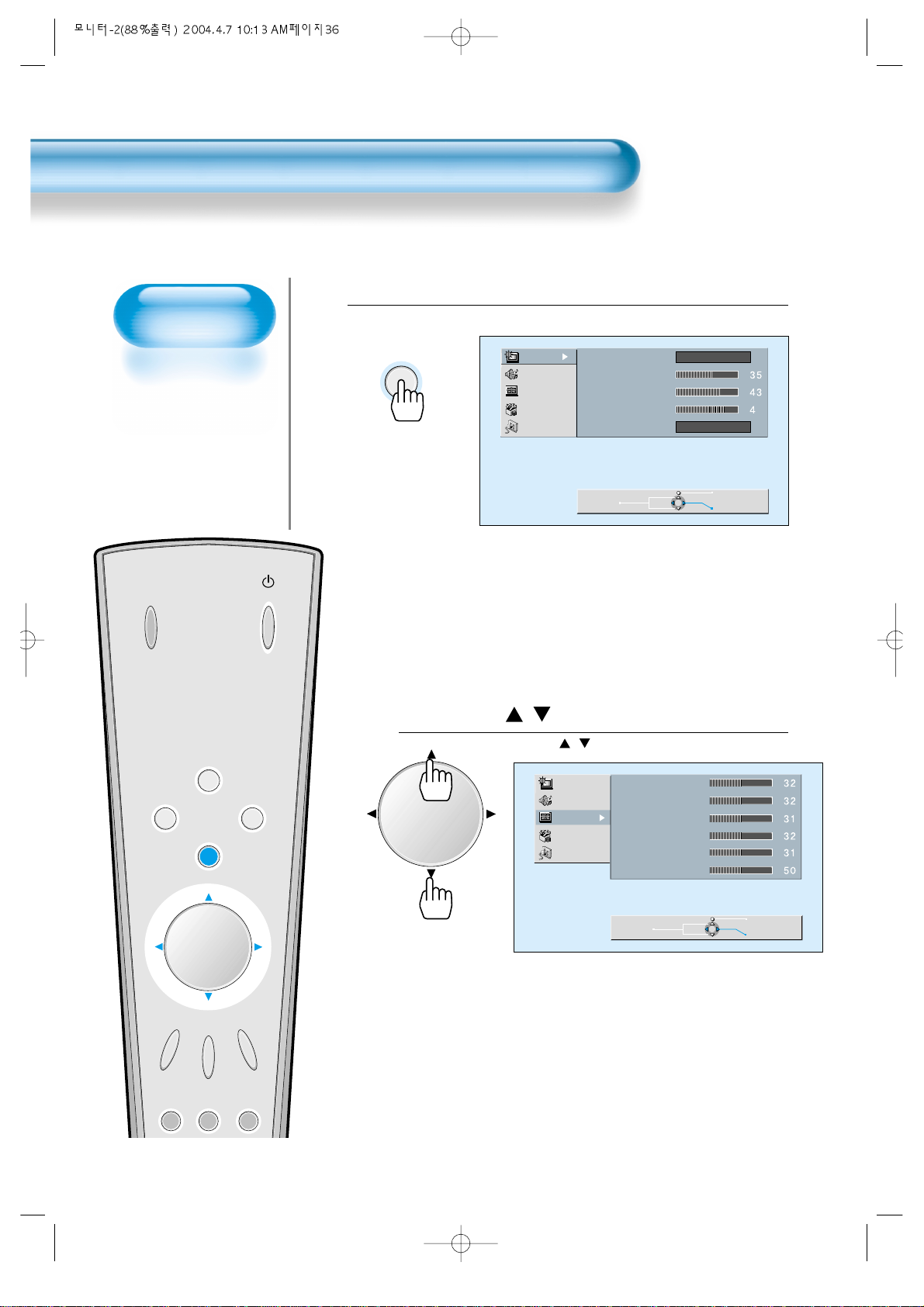
Press the MENU Button.
• The MENU screen as shown below will appear.
Press the / Button.
• Press the / buttons to select ‘Screen’.
1
2
36
Adjusting Screen Position and Size
MENU
VOLVOL
Picture
Sound
Screen
Utility
Input
Picture
Sound
Screen
Utility
Input
Mode
Brightness
Contrast
Sharpness
Color T emp.
Move
H. Size
V. Size
H. Position
V. Position
Phase
Frequency
Normal
Normal
Previous
Select
Move
Previous
Select
Page 37
37
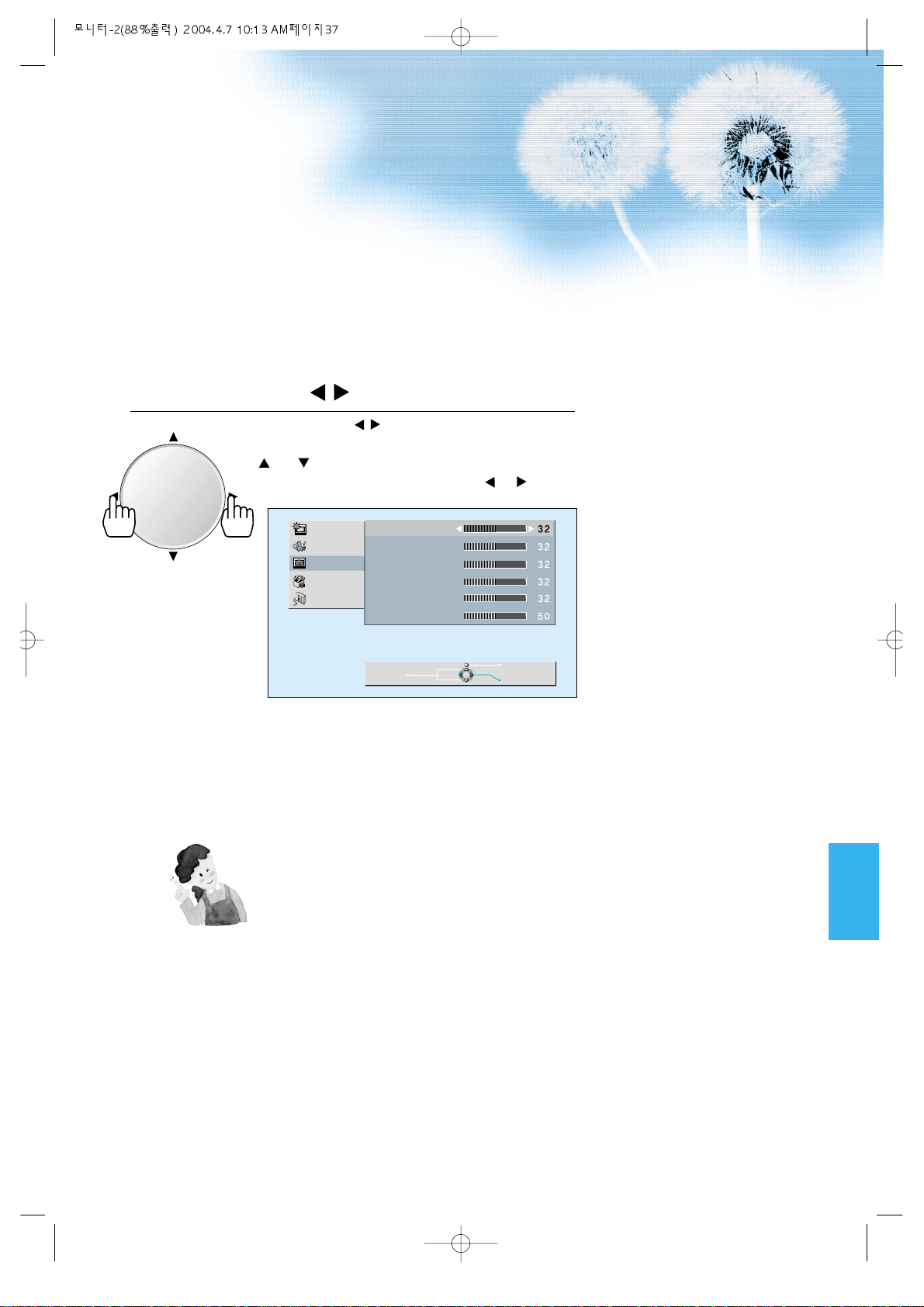
Press the V olume / Buttons.
• Press the V olume / buttons to select “Screen”.
• While you are in ‘Screen’ mode, press the
or button to select a desired item, and
then, adjust the value by pressing the or .
3
NOTES:
1) Horizontal/Vertical size and position values can be adjusted only in
the [PC] input mode.
2) H. Size: As the value increases, the screen width increases
3) V. Size: As the value increases, the screen height increases.
4) H. Position: Increasing value moves screen to the right.
As the value increases, the screen moves to the right.
5) V. Position: Increasing value moves screen up.
As the value increases, the screen moves up.
6) Phase: When there is zitter or blurring in image, adjust this value.
7) Frequency: When there is zitter or blurring in image, adjust this
value.
VOLVOL
Picture
Sound
Screen
Utility
Input
H. Size
V. Size
H. Position
V. Position
Phase
Frequency
Move
Previous
Adjust
Page 38
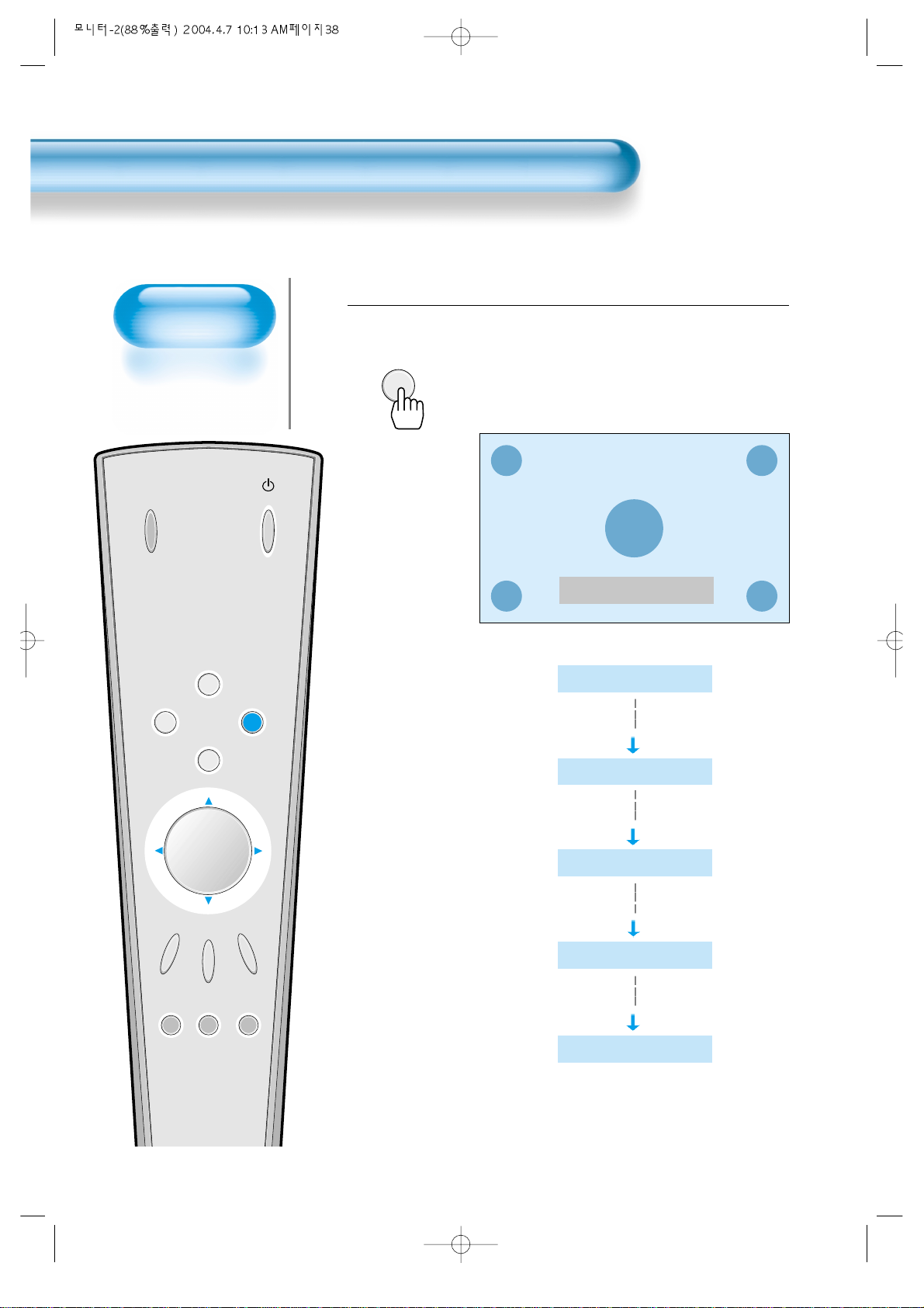
INPUT
SELECT
POWER
DISPLAY
ZOOM
-
PICTURE
MODE
SCREEN
MODE
FREEZE
MUTESOUND
MODE
SLEEP
ZOOM+
MENU
VOL VOL
Press the ‘ZOOM+’ Button.
• Press the ‘ZOOM+’ button to show currently selected
screen size.
• Each time you press the ‘ZOOM+’ button, the screen size
will increase stepwise in 0 ~ 20 scale.
• To reduce the screen size, press the [ZOOM-] button.
1
38
Enlarging
Screen Size
• You can view
enlarged size of the
screen with this
function
Enlarging Screen Size
Zoom Level 0
ZOOM+
Zoom Level 0
Zoom Level 5
Zoom Level 10
Zoom Level 15
Zoom Level 20
Page 39
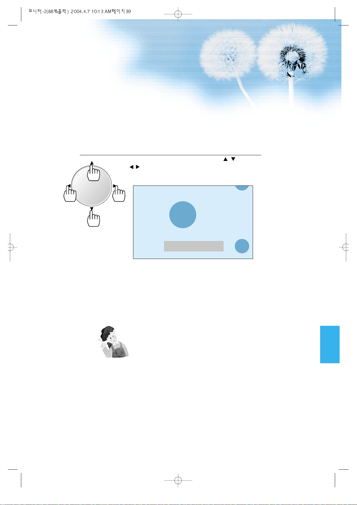
Move the Screen Position.
• While you are in the ‘Zoom’ mode, press the / ,
/ buttons to move screen stepwise up/down or
left/right, respectively .
2
39
NOTES:
* When the screen is enlarged, the pixel of the screen can
become thick and dim.
* When only the subtitle of zoom level remains, you can scroll
the image.
If subtitle or the zoom level disappears, press zoom key, and
scroll the image.
Zoom Level 6
VOLVOL
Page 40
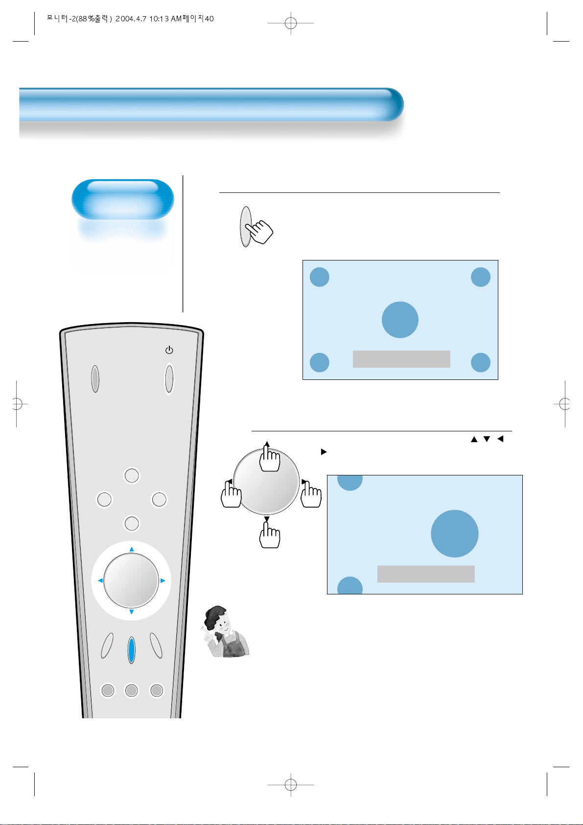
INPUT
SELECT
POWER
DISPLAY
ZOOM
-
PICTURE
MODE
SCREEN
MODE
FREEZE
MUTESOUND
MODE
SLEEP
ZOOM+
MENU
VOL VOL
Press the ‘FREEZE’ Button.
• If you wish to freeze a picture, press the ‘FREEZE’ button.
Y ou can still hear the sound.
• Press FREEZE button again to cancel the ‘FREEZE’
function.
• To view the enlarged images, press the [ZOOM+] button.
1
FREEZE
40
Watching a
Still Image
• You can view still
images temporarily
with this function.
However, displaying
the same images
such as still images
for a long time may
cause after-image
lagging.
Watching a Still Image
NOTES:
• Displaying the same images such as still images for a long
time may cause after-image lagging.
• In this case, such “after-image” may become less noticeable if
moving images are later displayed for a long time.
• However, an after-image may become a permanent one,
damaging the Plasma Display; therefore, avoid displaying the
same images for a long time.
Freeze
Zoom Level 7
Move the Screen Position.
• While you are in ‘FREEZE’ mode, press the / ,
/ buttons to move screen stepwise up/down and
left/right.
2
VOLVOL
Page 41
Adjusting Auto
Sound Mode
• Enjoy various sound
modes by selecting
your favorite Sound
Mode depending on
the kinds of moving
pictures.
Adjusting Auto Sound Mode
41
INPUT
SELECT
POWER
DISPLAY
ZOOM
-
PICTURE
MODE
SCREEN
MODE
FREEZE
MUTESOUND
MODE
SLEEP
ZOOM+
MENU
VOL VOL
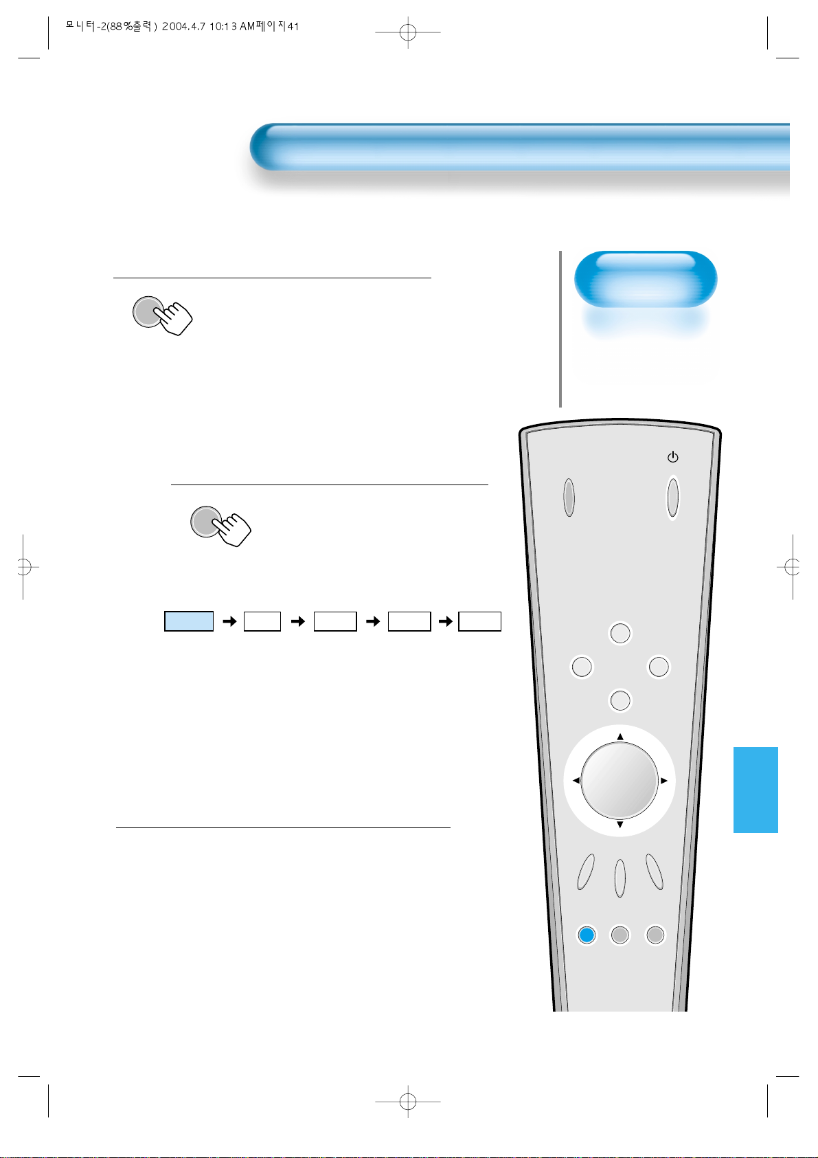
Select SOUND Mode.
SOUND
MODE
• Press the [SOUND MODE] on the
Remote Control.
• Press of the [SOUND MODE] for the
first time will display the current
SOUND MODE.
Every Press of the Button Changes Modes.
SOUND
MODE
• Each time you press the button, a
different sound mode appears.
The sequence used is as follows:
* Normal : Suitable for watching any motion picture
* Movie : Select this mode to simulate being at a movie theater
* Music : Ideal for listening to music
* News : Allows human voice to be heard more clearly
* User : Allows the user to adjust as desired.
MENU will Disappear .
• After selecting a desired SOUND Mode,
the on-screen menu will disappear in
about 2~3 seconds.
• Normal, Movie, Music, and News Modes
are factory preset values.
If you want to customize the sound modes
to your preference, refer to the following
page.
3
1
2
Normal Movie
Music UserNews
Page 42
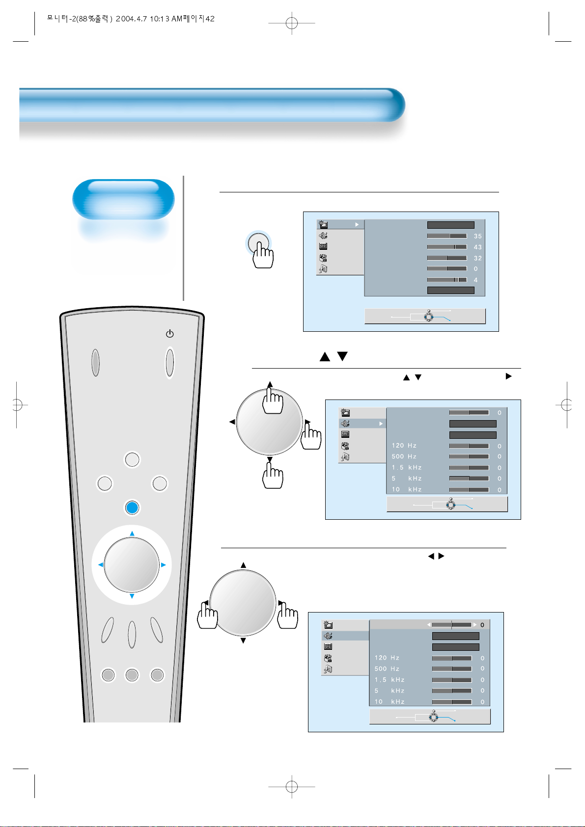
Customizing
Sound Mode
• This feature allows
the user to adjust to
his preference.
Customizing Sound Mode
42
Press the / Button.
• Select [SOUND] by the / buttons, then press the
button to display the following.
Select SOUND BALANCE.
• Select [SOUND BALANCE] by the / buttons, then
adjust it to required level.
• Sound balance is best at ‘0’.
• Sound Balance: Adjusts sound balance of left and right
speakers.
3
Press the MENU Button.
• The MENU Screen as below will be displayed.
1
2
MENU
Picture
Sound
Screen
Utility
Input
Mode
Brightness
Contrast
Color
Tint
Sharpness
Color T emp.
Normal
Normal
INPUT
SELECT
ZOOM
PICTURE
MODE
DISPLAY
-
VOL VOL
MENU
FREEZE
ZOOM+
SCREEN
POWER
MODE
VOLVOL
VOLVOL
Picture
Sound
Screen
Utility
Input
Picture
Sound
Screen
Utility
Input
Move
Balance
Spatial Effect
Sound Mode
Move
Balance
Spatial Effect
Sound Mode
Off
Normal
Previous
Select
Off
Normal
Previous
Select
MODE
MUTESOUND
SLEEP
Move
Previous
Adjust
Page 43
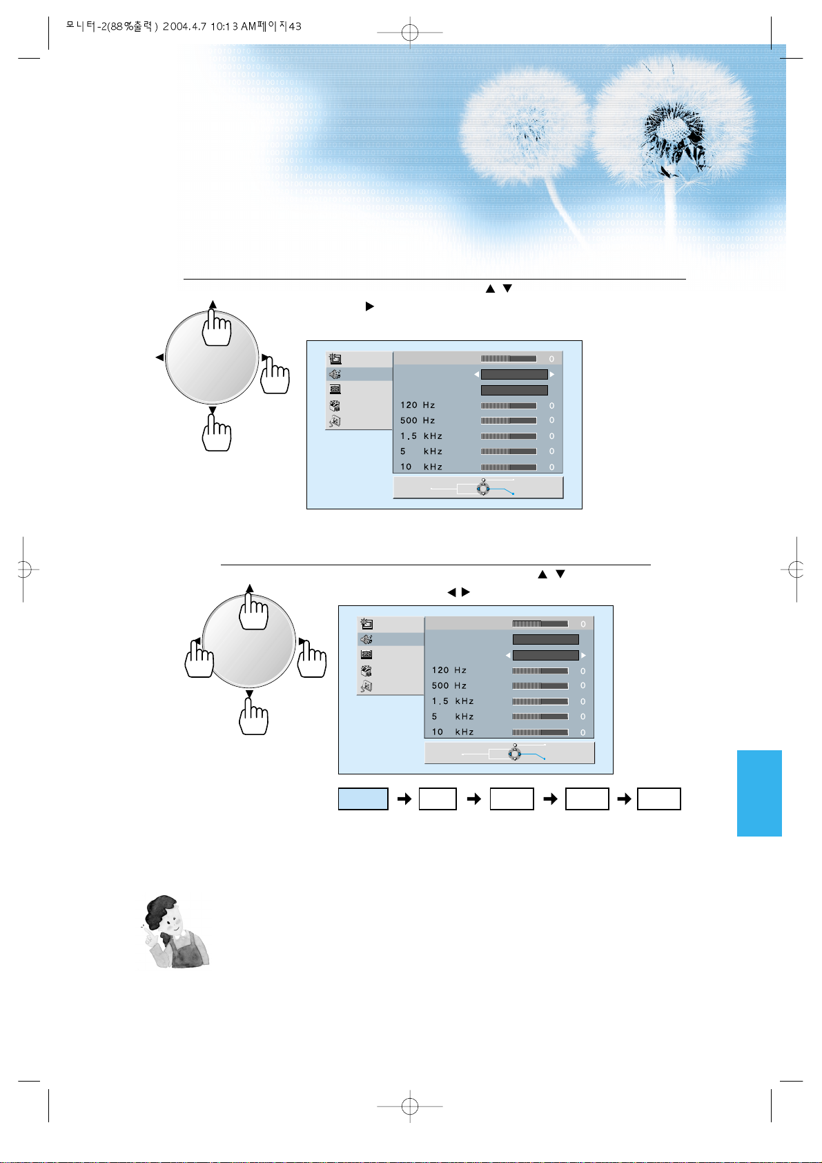
Select the Spatial Effect Mode.
• Select Spatial Effect by pressing the / buttons, then select ON/OFF by
pressing the button.
• Spatial Effect: Used to feel grotesque by emphasizing stereo ef fect.
Select the SOUND Mode.
4
5
43
• Select the Sound Mode by pressing the / buttons, then
adjust it by pressing the / buttons.
* Normal : Suitable for watching any motion picture
* Movie : Select this mode to simulate being at a movie
theater
* Music : Suitable for listening to music
* News : Allows human voice to be heard more clearly
* User : Allows the user to adjust as desired.
NOTES:
1) Custom Mode : Used as an Equalizer with which the user can adjust the sound frequency as desired.
2) If you modify the sound frequency in auto Sound Mode (News, Movie, Music, etc.), it is automatically
switched to the User Mode.
3) Low sound is emphasized as the frequency is lowered to 120 Hz, and high sound as raised to 10 KHz.
4) When the INPUT is MONO and if you make a connection to the Left Audio Input, you can hear from both
speakers in mono.
VOLVOL
VOLVOL
Normal Movie
Music UserNews
Picture
Sound
Screen
Utility
Input
Balance
Spatial Effect
Sound Mode
On
Normal
Picture
Sound
Screen
Utility
Input
Move
Balance
Spatial Effect
Sound Mode
Move
Previous
Adjust
Off
Normal
Previous
Adjust
Page 44

INPUT SIGNAL
• Used to select
INPUT signal of
external device
connected to the
PDP.
Selecting INPUT SIGNAL
44
Press the INPUT SELECT Button.
INPUT
SELECT
• Press the [INPUT SELECT] button on the Remote
Control or the PDP Display to select [COMPONENT 1]
or [COMPONENT 2].
• Each time you press the [input select] button, a different
screen mode appears. The sequence used is as
follows: COMPONENT 1 --> COMPONENT 2 -->
VIDEO 1 --> VIDEO 2 --> PC
1
NOTES:
* If an external device is not connected or INPUT signal is not
applied, Warning Message (“No Signal”) would be displayed.
* In this case, check if external device is connected and/or
terminal connection is properly done.
INPUT
SELECT
POWER
DISPLAY
ZOOM
-
PICTURE
MODE
SCREEN
MODE
FREEZE
MUTESOUND
MODE
SLEEP
ZOOM+
MENU
VOL VOL
PC
Component1
PC
Component2
Video1
Video2
Page 45
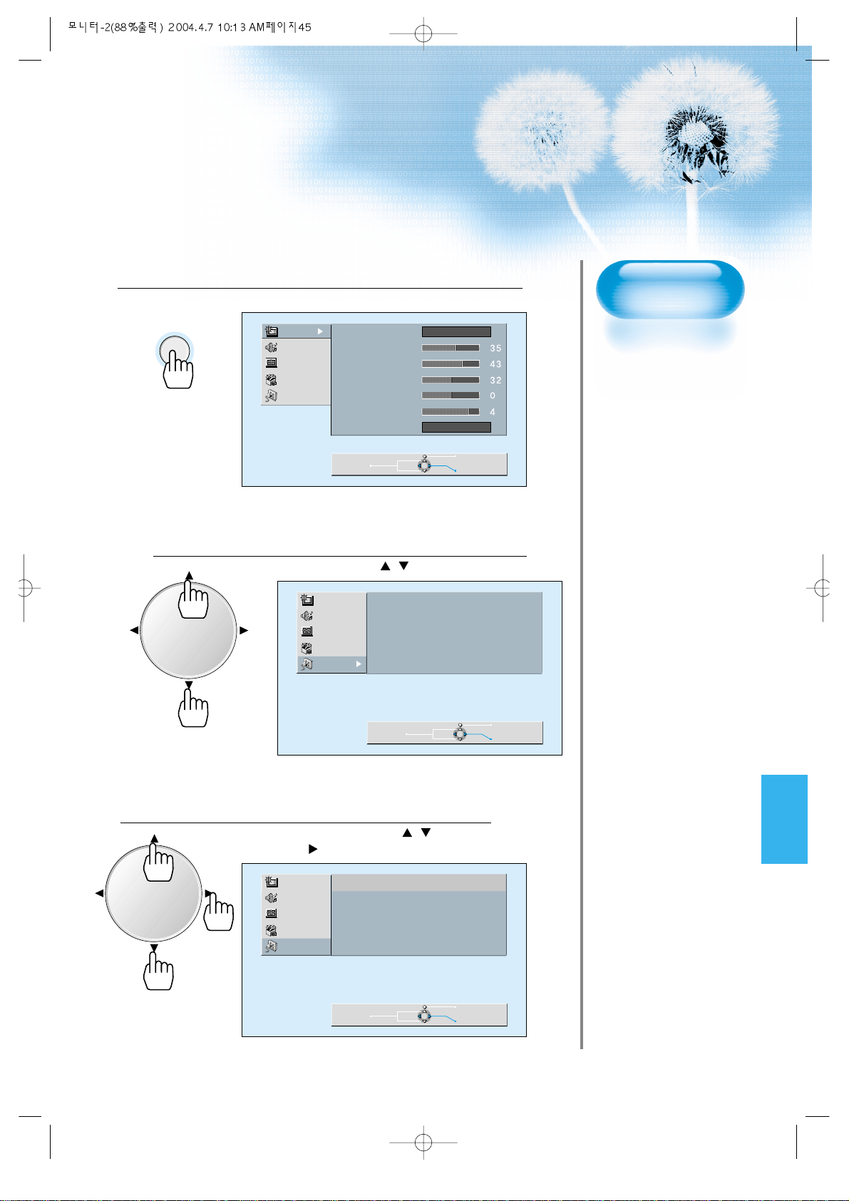
45
Press the MENU Button.
MENU
• Press the [MENU] button on the Remote Control.
1
Adjusting from the
MENU Screen
Select INPUT.
• Select [INPUT] by the / button.
Select INPUT SIGNAL.
• Select [INPUT SIGNAL] by the / buttons,
then press the button.
3
2
Picture
Sound
Screen
Utility
Input
Mode
Brightness
Contrast
Color
Tint
Sharpness
Color T emp.
Normal
Normal
VOLVOL
VOLVOL
Move
Picture
Sound
Screen
Utility
Input
Picture
Sound
Screen
Utility
Input
Component 1 (DTV/DVD)
Component 2 (DTV/DVD)
Move
PC
Component 1 (DTV/DVD)
Component 2 (DTV/DVD)
Video 1
Video 2
PC
Video 1
Video 2
Previous
Select
Previous
Select
Move
Previous
Select
Page 46
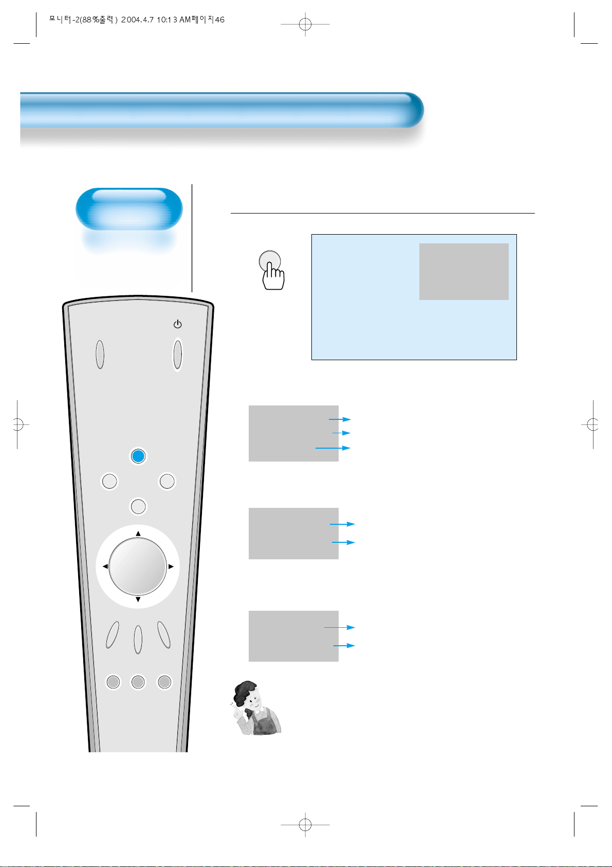
Checking the
Current Input Signal
• Used to check the
INPUT signal mode,
resolution,
frequency, etc. of the
current screen.
Checking the Current Input Signal
46
Press the DISPLAY Button.
DISPLAY
• Press the [DISPLAY] button on the Remote Control.
1
1. If you watch Digital Broadcasts:
Displays which input terminal is used, and indicates the input signal mode.
Indicates the horizontal and vertical resolution of the current INPUT signal.
Indicates the frequency of the current INPUT signal.
INPUT
SELECT
POWER
DISPLAY
ZOOM
-
PICTURE
MODE
SCREEN
MODE
FREEZE
MUTESOUND
MODE
SLEEP
ZOOM+
MENU
VOL VOL
Component 1
1920 x 1080
60 Hz
Component 1
1920 x 1080
60 Hz
2. If you watch DVD image:
Displays which input terminal is used, and indicates the signal mode.
Indicates the mode and frequency of the current INPUT signal.
Component 2
YUV 60 Hz
3. If you watch VCR image:
Displays which input terminal is used, and indicates the signal mode.
Indicates the mode and frequency of the current INPUT signal.
Video 1
NTSC 60 Hz
NOTES:
1) PLASMA can receive NTSC, PAL, SECAM, etc.
2) “1920 x 1080” displayed in the INPUT signal does not indicate
the resolution of the monitor, but the signal that is sent by
Digital Broadcasting Receiver.
Page 47
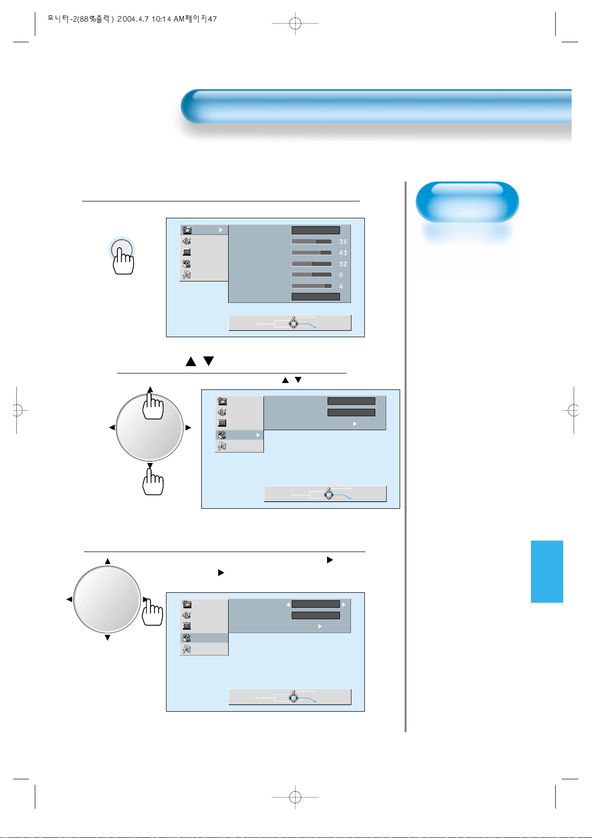
Selecting
Languages
• Used to select
transparency of the
background screen
and language used
in MENU.
Press the MENU Button.
MENU
• The MENU screen will be displayed as below .
Press the / Button.
• Select [Utility] by the / button.
Select the MENU BACKGROUND SCREEN.
• Select the MENU [Background Screen] by pressing the button.
• Every press of the button while you are in the[MENU Background
Screen] would switch between Transparent/Opaque.
3
1
2
Selecting MENU Background Screen and Language
4747
VOLVOL
Picture
Sound
Screen
Utility
Input
Mode
Brightness
Contrast
Color
Tint
Sharpness
Color T emp.
Move
Normal
Normal
Picture
Sound
Screen
Utility
Input
Background
Language
Initialize
Move
Previous
Select
Opaque
English
Press key
Previous
Select
VOLVOL
Picture
Sound
Screen
Utility
Input
Background
Language
Initialize
Move
Press key
Opaque
English
Previous
Adjust
Page 48
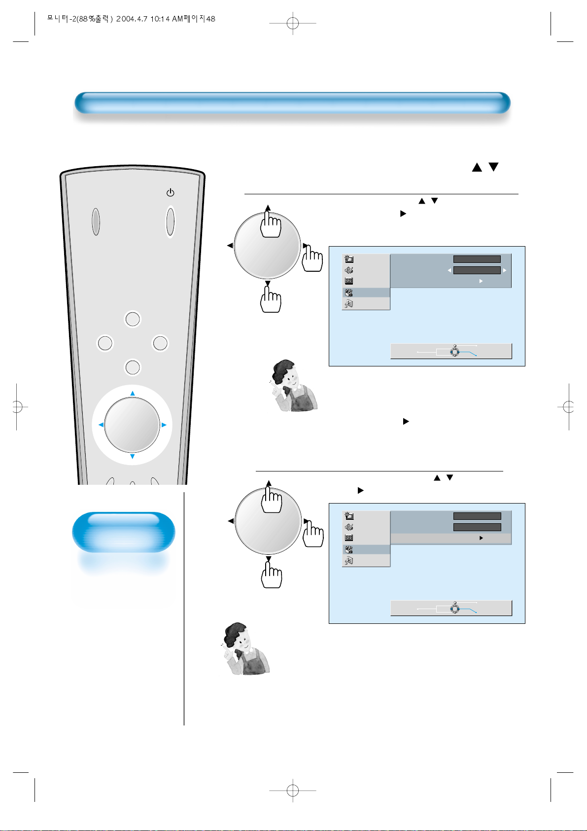
INPUT
SELECT
POWER
DISPLAY
ZOOM
-
ZOOM+
MENU
VOL VOL
Back to
Initialization
• You can restore the
values of the
adjustment/setting
made in the MENU
to factory settings.
Selecting MENU Background Screen and Languages
Select MENU LANGUAGE SELECT by the /
Button.
• Select LANGUAGE by the / button.
• Every press of the button while you are in the
[LANGUAGE] mode would cycle through the different
languages.
INITIALIZA TION will Start.
• Select [INITIALIZATION] by the / buttons, then
press the button to start initialization.
4
5
48
When [INITIALIZA TION] is completed:
* When [INITIALIZATION] is completed, those values that have been set
in the User Mode of [SCREEN MODE] and [SOUND MODE] will be
returned to the factory preset values.
* When you try to initialize, be advised that you should think it over.
* The items in the [SCREEN] Menu in PC INPUT are also initialized (i.e.,
H. Size, V. Size, H. Position, V. Position, Phase, Frequency, etc.)
* Language, volume, OSD background and input mode are not initialized.
VOLVOL
VOLVOL
NOTES:
*
When Power is turned ON first time, ‘SELECT
LANGUAGE’ Mode will be displayed, then, select a
desired language by button. (Displayed only once)
Picture
Sound
Screen
Utility
Input
Background
Language
Initialize
Opaque
English
Press key
Picture
Sound
Screen
Utility
Input
Move
Background
Language
Initialize
Move
Previous
Opaque
English
Press key
Previous
Adjust
Adjust
Page 49
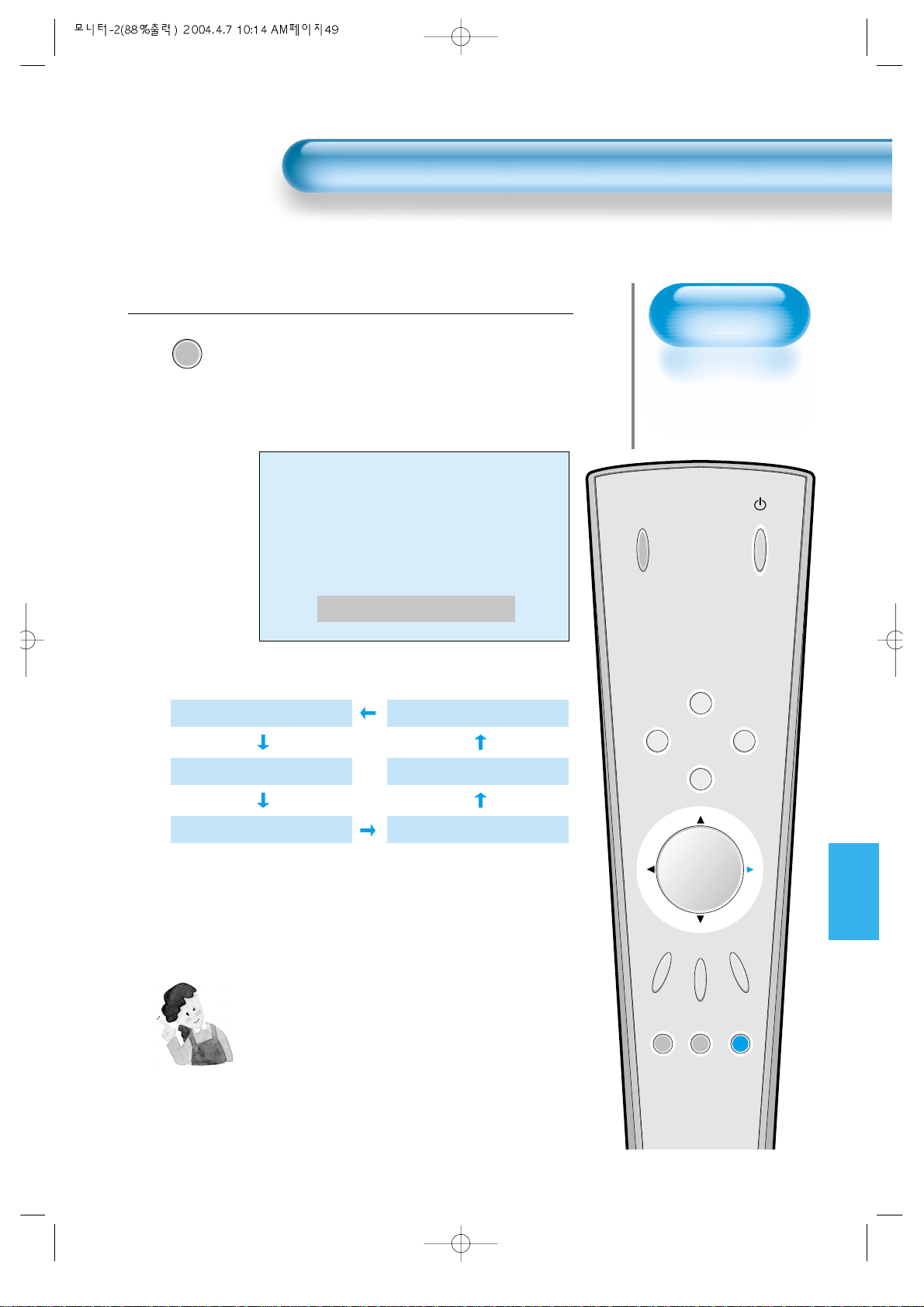
Setting
Sleep Timer
• SLEEP TIMER turns
the Monitor off after
a preset time.
Press the SLEEP Button.
SLEEP
• Press the [SLEEP] button on the Remote Control.
• Pressing the [SLEEP] button first time will display the
current setting for SLEEP TIMER.
• To cancel the SLEEP TIMER, press the [SLEEP] button to
select ‘OFF’.
1
Setting Sleep Timer
49
INPUT
SELECT
POWER
DISPLAY
ZOOM
-
PICTURE
MODE
SCREEN
MODE
FREEZE
MUTESOUND
MODE
SLEEP
ZOOM+
MENU
VOL VOL
NOTES:
1) On-screen information disappears if you do not
take any action for about two seconds after
pressing the SLEEP button.
2) If you turn the Monitor off after setting SLEEP, the
setting is erased.
Sleep Timer off
Sleep Timer off
Sleep Timer 15 Minutes
Sleep Timer 30 Minutes
Sleep Timer 120 Minutes
Sleep Timer 90 Minutes
Sleep Timer 60 Minutes
Page 50
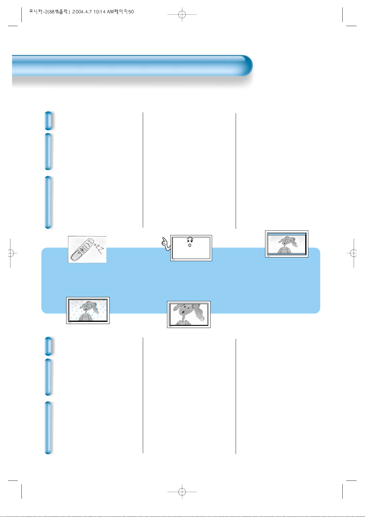
Before Requesting Service
50
Before Requesting Service
St
yo
mm
ps
C
h
e
c
k
s
A
c
t
i
o
n
• There are empty spots at the top
and the bottom area of the screen.
• Check if the screen size of an image
is wider than 16:9 aspect ratio
(theater screen size).
• When video screen is wider than
16:9 aspect ratio, you may see dark
areas at the top and the bottom of
the screen.
• The Display makes a snapping
sound.
• Check if the pictures and sound are
normal.
• This sound is produced due to
variations in room temperature.
• This sound does not indicate that the
Display has a problem if the pictures
and sound can be viewed and heard
properly.
• Remote control does not
function properly.
• Check for any obstacle between the
Remote Control and the Display.
• Check for dead batteries and
incorrect battery orientation.
• Check if the Remote Control is the
right one.
• Remove any obstacle between the
Remote Control and the Display.
• Replace batteries and use the correct
polarity (+) or (-) of the batteries.
• Use the pertinent Remote Control
proper to the model.
St
yo
mm
ps
C
h
e
c
k
s
A
c
t
i
o
n
• Screen size is suddenly
changed.
• The screen size of a video image
may not be matched to the size of
the dark initial screen.
• Check by using other video tape.
• There are spots on the screen
or screen rolls.
• Check if your product is affected by
any interference from automobiles,
high-voltage transmission lines, neon
signs or other potential sources.
Before requesting service, check the following points once again.
Page 51
51
SPECIFICA TIONS
In the event that the product has been affected by rain water:
TURN OFF IMMEDIATELY AND REMOVE POWER CORD.
Immediately wash it with clean water, and dry it away from
sunlight, then call for service from the nearest Service Centre.
Do not plug the Power Cord back in since there is risk of electric
shock and damage to the product.
*
Appearance and specifications of this product are subject to change for improving the product without prior notice.
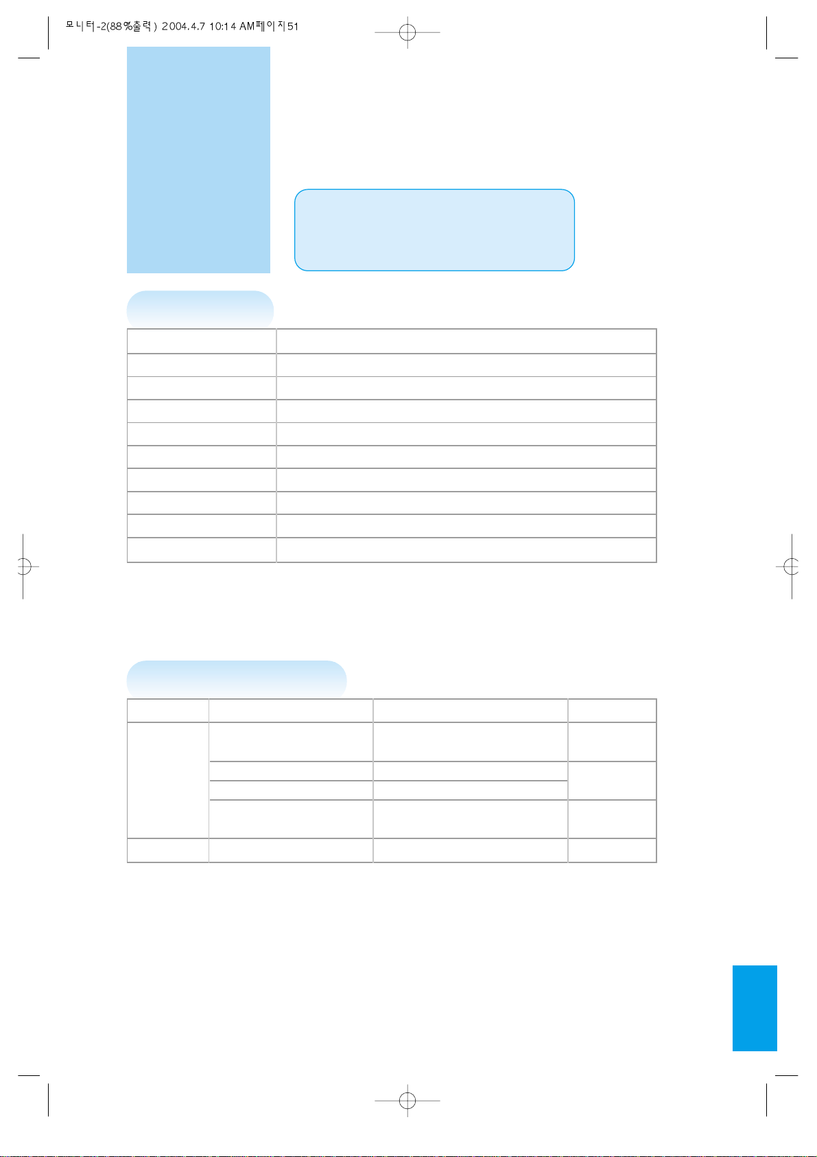
DISPLAY UNIT
Model KPP-4200D
Diagonal Size 106cm (42”)
Screen Aspect Ratio 16 : 9
Display Resolution 853(H) X 480(V) dots
Pixel Pitch 1.08(H) X 1.08(V) mm
Output Color 16,770,000 Colors
Video Signal NTSC, P AL, SECAM, P AL-M/N, NTSC4.43
Dimension 1039(W) X 628(H) X 80(D) mm.
Weight 30Kg
Power Requirement AC 100-240V, 50/60Hz
INPUT/OUTPUT TERMINAL
INPUT/OUTPUT ITEMS VIDEO AUDIO
COMPONENT INPUT
DTV/DVD ONLY (LEFT/RIGHT)
(Y, Pb/Cb, Pr/Cr), 2 sets 2 sets
EXTERNAL VIDEO INPUT two RCA jacks (LEFT/RIGHT)
INPUT S-VIDEO INPUT two 4 pin Mini DIN jack 2 sets
Computer(PC)
one 15 pin D-sub jack (LEFT/RIGHT)
(R, G, B, H, V) 1 set
AUDIO OUTPUT SPEAKER OUTPUT(sold separately) 16W (two 8W)
 Loading...