

DAEWOO KOR-161H2A Service Manual

S/M No. : R161G2A001
Service Manual
Microwave Oven
Model: KOR-161G2A
KOR-161H2A
DAEWOO ELECTRONICS CO., LTD.
PRECAUTIONS TO BE OBSERVED BEFORE ANDI
DURING SERVICING TO AVOID POSSIBLE
EXPOSURE TO EXCES SIVE MICR OWAVE ENERGY
(a) Do not operate or allow the oven to be operated with the door open.
(b) Make the following safety checks on all ovens to be serviced before activating the magnetron or other microwave
source, and make repairs as necessary: (1) Interlock operation, (2) Proper door closing, (3) Seal and sealing
surfaces (arcing, wear, and other damage), (4) Damage to or loosening of hinges and latches, (5) Evidence of
dropping or abuse.
(c) Before turning on power to the microwave oven for any service test or inspection within the microwave
generating compartments, check the magnetron, wave guide or transmission line, and cavity for proper
alignment, integrity, and connections.
(d) Any defective or misadjusted components in the interlock, monitor, door seal, and microwave generation and
transmission systems shall be repaired, replaced, or adjusted by procedures described in this manual before the
oven is released to the owner.
(e) A microwave leakage check to verify compliance w ith the Federal performance standard should be performed on
each oven prior to release to the owner.
SAFETY AND PRECAUTIONS........................................................................................................... 2
1. FOR SAFE OPERATION .............................................................................................................. 2
2. FOR SAFE SERVICE PROCEDURES ......................................................................................... 2
SPECIFICATIONS............................................................................................................................... 3
EXTERNAL VIEW................................................................................................................................ 4
1. OUTER DIMENSION..................................................................................................................... 4
2. FEATURE DIAGRAM.................................................................................................................... 5
3. CONTROL PANEL........................................................................................................................ 6
INSTALLATION................................................................................................................................... 8
OPERATIONS AND FUNCTIONS....................................................................................................... 9
DISASSEMBLY AND ASSEMBLY...................................................................................................... 10
INTERLOCK MECHANISM AND ADJUSTMENT............................................................................... 17
TROUBLE SHOOTING GUIDE .......... ... ......... ... .................. ... ......... ... ........ ... ... ......... ... ......... ... ........... 18
MEASUREMENT AND TEST...................................................... ......... ................. ......... ......... ........... . 22
1. MEASUREMENT OF THE MICROWAVE POWER OUTPUT ...................................................... 22
2. MICROWAVE RADIATION TEST................................................................................................. 23
3. COMPONENT TEST PROCEDURE............................................................................................. 24
WIRING DIAGRAM.............................................................................................................................. 25
PRINTED CIRCUIT BOARD................................................................................................................ 26
1. CIRCUIT CHECK PROCEDURE .................................................................................................. 26
2. PCB CIRCUIT DIAGRAM.............................................................................................................. 29
3. P.C.B. LOCATION NO. ................................................................................................................. 30
EXPLODED VIEW AND PARTS LIST................................................................................................. 31
1. DOOR ASSEMBLY....................................................................................................................... 31
2. CONTROL PANEL ASSEMBLY.................................................................................................... 31
3. TOTAL ASSEMBLY....................................................................................................................... 31

SAFETY AND PRECAUT IONS
CAUTION
This Device is to be Serviced Only by Properly Qualified Service Personnel. Consult the Service M anual for
Proper Service Procedures to Assure Continued Safety Operation and for Precautions to be Taken to Avoid Possible
Exposure to E xcessive Microw ave Energy.
1. FOR SAFE OPERATION
Damage that allows the microwave energy ((that cooks or heats the food) to escape will result in poor cooking and may
cause serious bodily injury to the operator.
IF ANY OF THE FOLLOWING CONDITIONS EXIST, O PERATOR MUST NOT USE THE APPLIANCE.
(Only a trained service personnel should make repairs.)
1) A broken door hinge.
2) A broken door viewing screen.
3) A broken front panel, oven cavity.
4) A loosened door lock.
5) A broken door lock.
The door gasket plate and oven cavity surface should be kept clean.
No grease, soil or spatter should be allowed to build up on these surfaces or inside the oven.
DO NOT ATTEMPT TO OPERATE THIS APPLIANCE W ITH THE DOOR OPEN . The microwave oven has concealed
switches to make sure the power is turned off when the door is opened. Do not attempt to defeat them.
DO NOT ATTEMPT TO SERVICE THIS APPLIANCE UNTIL YOU HAVE READ THIS SERVICE M ANUAL.
2. FOR SAFE SERVICE PROCEDURES
1) If the oven is operative prior to servicing, a microwave emission check should be performed prior to servicing the oven.
2) If any certified oven unit is found to servicing, a m icrowave emission check should be performed prior to servicing
the oven.
(a) inform the m anufacturer, importer or assembler,
(b) repair the unit at no cost to the owner,
(c) attempt to ascertain the cause of the excessive leakage,
(d) tell the owner of the unit not to use the unit until the oven has been brought into compliance.
3) If the oven operates with the door open, the service person should tell the user not to operate the oven and contact
the manufacturer and CDRH immediately.
CAUTION
MICROWAVE RADIATION
PERSONNEL SHOULD NOT BE EXPOSED TO THE M ICROWAVE ENERGY W H ICH MAY R ADIATE FROM THE
MAGNETRON OR OTHER MICROWAVE GENERATING DEVICE IF IT IS IMPROPERLY USED OR CONNECTED.
ALL INPUT AN D OU TPUT MICROWAVE CONNECTIO NS. WAVEGUIDE FLANGES AND GASKETS MUST BE
SECURE. NEVER OPERATE THE DEVICE WITHOUT A MICROWAVE ENERGY ABSORBING LOAD ATTACHED.
NEVER LOOK INTO AN OPEN WAVEGUIDE OR ANTENNA WHILE THE DEVICE IS ENERGIZED.
SPECIFICATIONS
MOD EL KOR-161G/161H
POWER SUPPLY 120V~60Hz, SINGLE PHASE WITH GROUNDING
POWER
CONSUMPTION
MICROWAVE ENERGY OUTPUT 1100W
MICROWAVE FREQUENCY 2450MHz
OUTS IDE DIMENSIONS (W X H X D) 589 x 339 x 464 m m (23.2 x 13.3 x 18.3 in.)
CAVITY DIMEN SIONS (W X H X D) 399 x 263 x 426 m m (15.7 x 10.4 x 16.8 in.)
NET W E IGHT APPRO X. 18.9 Kg ( 41.6 lbs.)
TIME R 99 m in. 99 s ec .
FUNCTION SELECTIONS MICROWAVE
POWER SELECTIONS 10 LEVELS
CAVITY VOLU M E 1.6 C u.Ft.
SPECIFICATIONS ARE SUBJECT TO CHANG E WITHOUT NOTICE.
MICRO WAVE 1500W
GRILL
COMBINATION
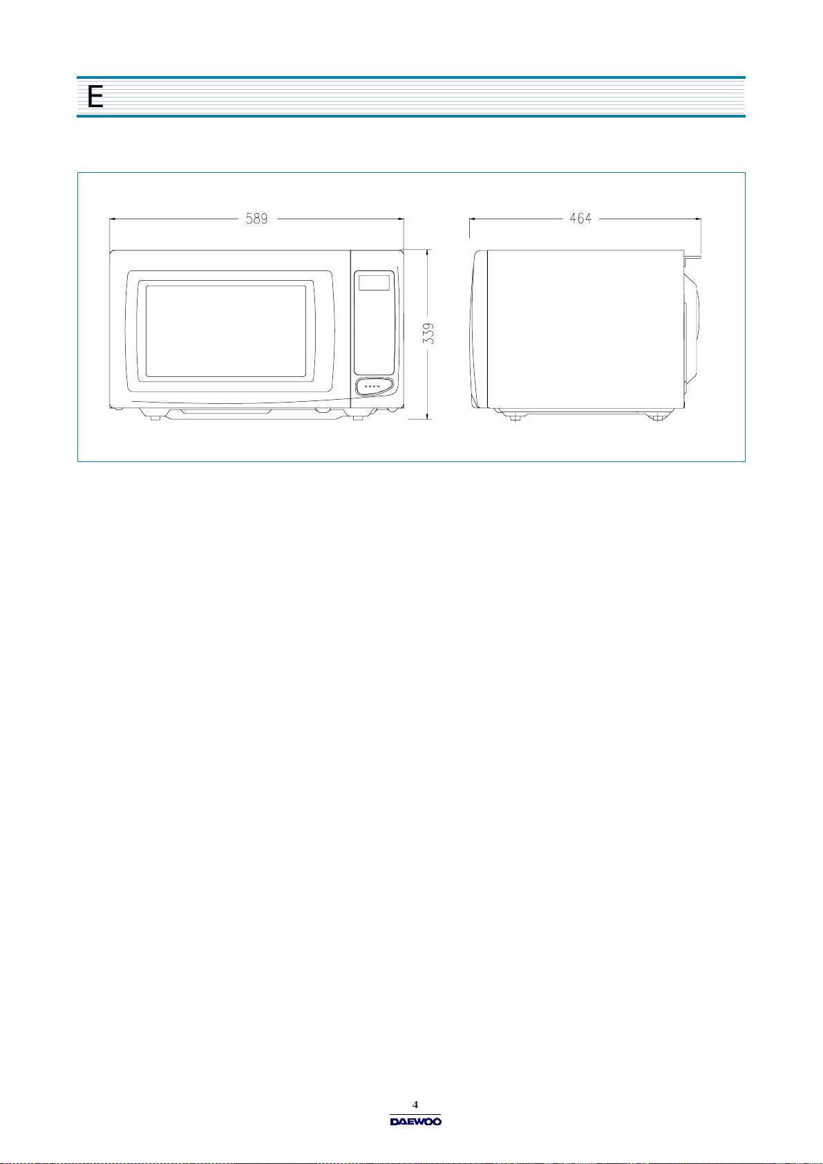
EXTERNAL VIEW
1. OUTER DIMENSION
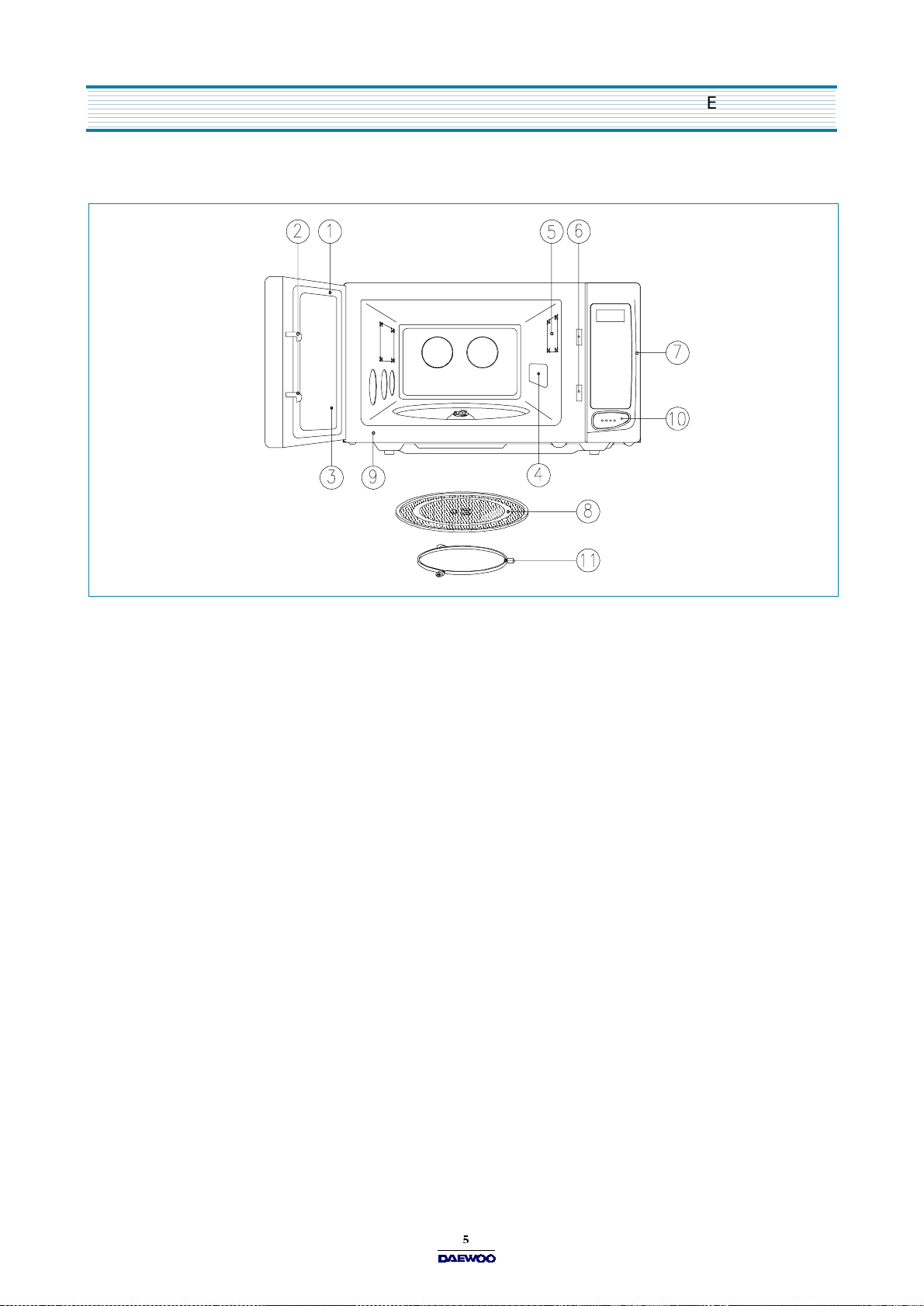
2. FEATURE DIAGRAM
EXTERNAL VIEW
1. DOOR SEAL
Door seal m aintains the microwave within the oven cavity and prevents microwave leakage.
2. DOOR HOOK
When door is closed, it will automatically lock shut. If door is opened while oven is operating, magnetron tube will immediately stop operating.
3. DOOR SCREEN
Allows viewing of food. M icrowave cannot pass through perforations in screen.
4. SPATTER SHIELD
Protects the microwave outlet from splashes of cooking foods.
5. OVEN LAMP
Automatically turns on during oven operating.
6. SAFETY INTERLOCK SYSTEM
7. CONTROL PANEL
8. GLASS COOKING TRAY
Made of special heat resistant glass. The tray must always be in proper position before operating. Do not cook food directly
on the tray..
9. OVEN FRONT PLATE
10. DOOR OPENING BUTTON
To open the door, push the door opening button. When door is closed, it will automatically lock shut. If door is opened while
oven is operating, magnetron tube will imm ediately stop operating.
11. ROLLER GUIDE
Supports the glass cooking tray.
EXTERNAL VIEW
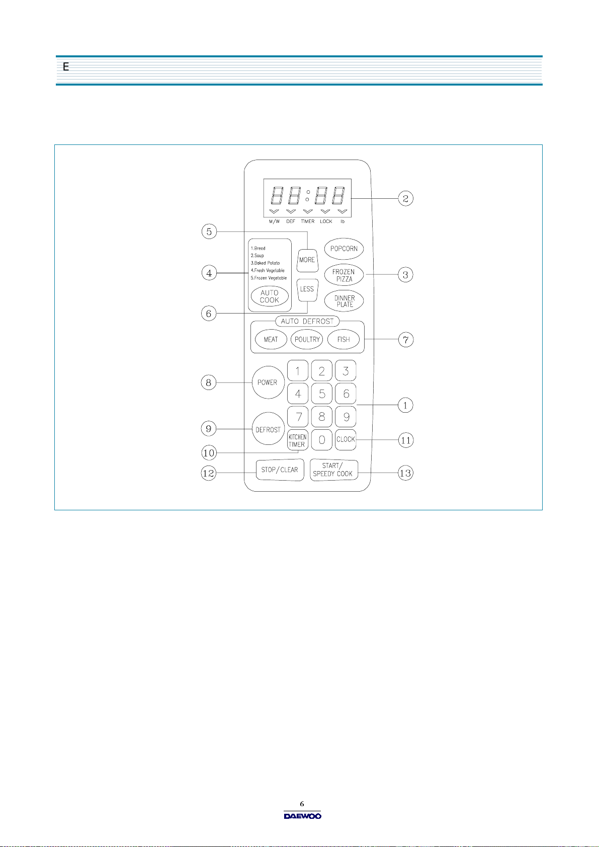
3. CONTROL PANEL
- KOR-161G2A
1. Tim e set pad -
2. Display
3. One touch
4. Auto cook
5. More
6. Less
7. Auto Defrost
8. Power
9. Defrost
10. Kitchen Timer
11. Clock
12. Stop/Clear
13. Start/Speedy cook
- Cooking time, power level, indicators and present time are displayed.
- Used to add time to cooking.
- Us ed to remove ti me from coo k i n g.
- Us ed to se t powe r l e ve l.
- Us ed to d efrost foo d s.(for time)
- Used to set clock .
Used to set the cooking time and the present time.
- Used to cook or reheat specific quantities of food.
- Used to cook or reheat.
- Used to defrost foods.(for weight)
- Used as a minute timer, delay cooking, hold setting after cooking.
- Used to stop the oven operation or to delete the cooking data.
- Used to start the oven and also used to set a reheat time.
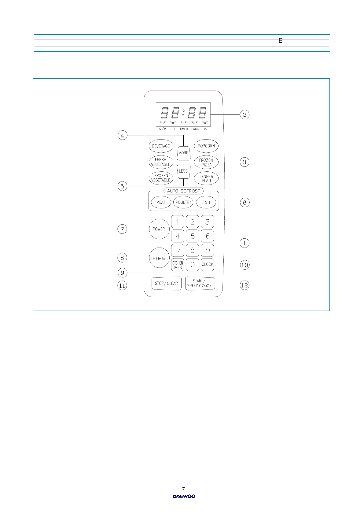
- KOR-161H2A
EXTERNAL VIEW
1. Tim e set pad
2. Display
3. One touch
4. More
5. Less
- Used to add time to cooking.
- Us ed to remove ti me from coo k i n g.
6. Auto Defrost
7. Power
8. Defrost
9. Kitchen Timer
10. Clock
11. Stop/Clear
- Used to set the cooking time and the present time.
- Cooking time, power level, indicators and present time are displayed.
- Used to cook or reheat specific quantities of food.
- Used to defrost foods.(for weight)
- Us ed to se t powe r l e ve l.
- Us ed to d efrost foo d s.(for time)
- Used as a minute timer, delay cooking, hold setting after cooking.
- Used to set clock.
- Used to stop the oven operation or to delete the cooking data.
12. Start/Speedy cook
- Used to start the oven and also used to set a reheat time.
INSTALLATION
1. Steady, flat location
This m icrow ave oven should be set on a steady, flat surface.
2. Leave space behind and side
All air vents should be kept a clearance. If all vents are covered during operation, the oven may overheat and, eventually,
cause oven failure.
3. Away from radio and TV sets
Poor television reception and radio interference m ay result if the oven is located close to a TV, radio, antenna or feeder
and so on.
4. Away from heating appliances and water taps
Keep the oven aw ay from hot air, steam or splash when choosing a place to position it, or the insulation might be adversely
affected and breakdown s occur.
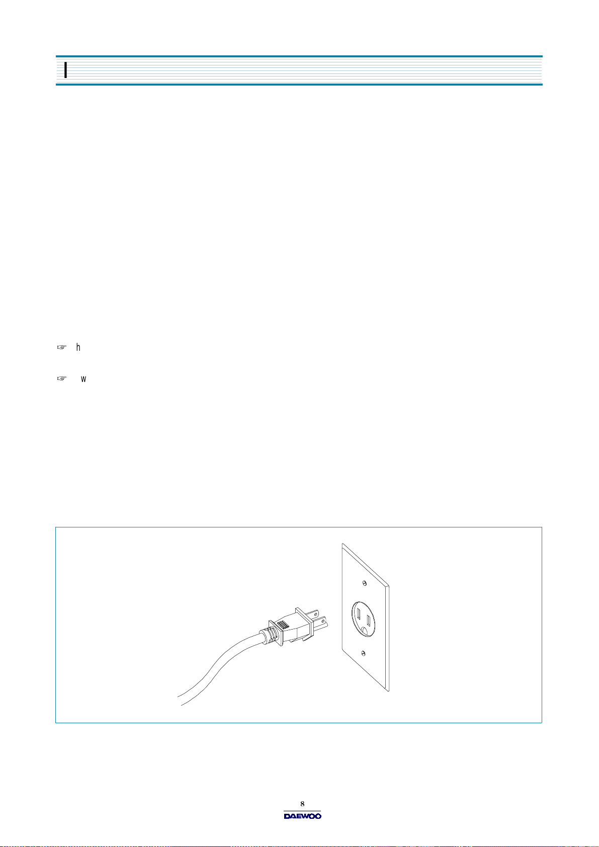
5. Power supply
Check your local power source.
This microwave oven requires a current of approxim ately 12 am peres, 120 Volts, 60 Hz grounded outlet.
Power supply cord is about 0.8 meters long.
1. A short power-supply cord is provided to reduce the risks resulting from becoming entangled in or tripping over a
longer cord.
2. Longer cord sets or extension cords are available and may be used if care is exercised in their use.
3. If a long cord or extension cord is used:
1) The marked electrical rating of the cord set or extension cord should be at least as great as the electrical rating of
the appliance.
2) T he extension cord must be a grounding type 3-wire cord.
3) The longer cord should be arranged so that it will not drape over the counter top or tabletop w here it can be pulled
on by children or tripped over unintentionally.
6. Examine the oven after unpacking for any damage such as:
A misaligned door, broken door or a dent in cavity.
If any of the above are visible, D O NO T INSTALL, and notify dealer immediately.
OPERATIONS AND F U NCTIONS
1. Connect the main lead to an electrical outlet.
2. After placing the food in a suitable container, open the oven door and put it on the glass tray. The glass tray must always
be in place during cooking.
3. Close the door securely.
4. The oven door can be opened at any tim e during operation by touching the door release button on the control panel.
The oven will automatically shut off. To restart the oven, close the door and then touch START.
5. Each time a pad is touched, a BEEP will sound to acknowledge the touch.
6. The oven automatically cook on full power unless set to a lower power level.
7. The display will show :0 w hen the oven is plugged in.
8. Time clock returns to the present tim e w hen the cooking time ends.
9. When the STOP/CLEAR pad is touched during the oven operation, the oven stops cooking and all inform ation retained.
To erase all information (except the present time), touch the STO P/CLEAR pad once more. If the oven door is opened
during the oven operation, all information is retained.
10. If the START pad is touched and the oven does not operate, check the area betw een the door and door is closed
securely. The oven will not start cooking under the door is completely closed or the program has been reset.
Make sure the oven is properly installed and plugged into the electrical outlet.
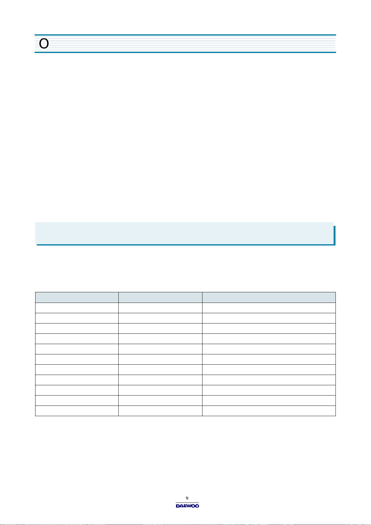
Wattage output chart
The power level is set by pressing the POWER pad. The chart shows the display, the power level and the percentage of
power.
Touch POWE R pad. Power level (D isplay) Approximate Percentage of Power
Once P-HI 100 %
Tw ice P-9 0 9 0 %
3 times P-80 80 %
4 times P-70 70 %
5 times P-60 60 %
6 times P-50 50 %
7 times P-40 40 %
8 times P-30 30 %
9 times P-20 20 %
10 times P-10 10 %
11 times P -00 0 %
ISASSEMBLY AND ASSEMBLY
- Cautions to be observed when trouble shooting.
Unlike many other appliances, the m icrow ave oven is high-voltage, high-current
equipm ent. It is completely safety during normal operation. H owever, carelessness in servicing the oven can result in an
electric shock or possible danger from a short
circuit. You are asked to observe the following precautions carefully.
1. Alw ays remove the power plug from the outlet before servicing.
2. Use an insulated screw driver and ware rubber gloves when servicing the high voltage side.
3. D ischarge the high voltage capacitor before touching any oven components or wiring.
1) Check the grounding.
Do not operate on a two-w ire extension cord.
The microwave oven is designed to be used
with grounded. It is im perative, therefore, to makes
sure it is grounded properly before beginning repair work.
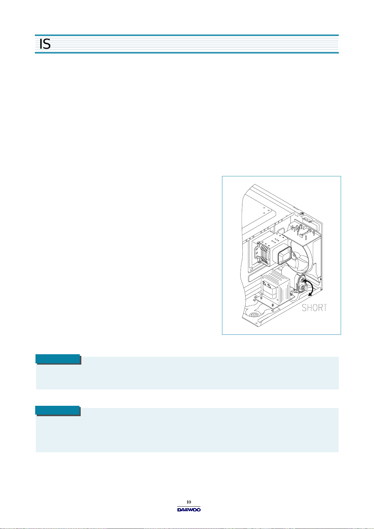
2) Warning about the electric charge in the high voltage capacitor.
For about 30 seconds after the operation stopped and
electric charge remains in the high voltage capacitor.
When replacing or checking parts, short between oven chassis
and the negative high terminal of the high voltage capacitor, by
using a properly insulated screwdriver to discharge.
4. When the 15A fuse is blown out due to the operation of the m onitor
switch; replace prim ary interlock switch, secondary interlock switch
and interlock monitor switch.
5. After repair or replacement of parts, make sure that the screws are
properly tightened, and all electrical connections are tightened.
6. Do not operate w ithout cabinet.
CAUTION
Service personnel should rem ove their watches whenever working close to or replacing the magnetron.
CAUTION
When servicing the appliance, need a care of touching or replacing high potential parts because of electrical
shock or exposing microvave. These parts are as follows - HV Transformer, Magnetron, HV Capacitor, HV Diode.
 Loading...