

Page 1

SAFETY AND PRECAUTIONS
1. FOR SAFE OPERATION
Dam age that allow s the microwave energy (that cooks or heats the food) to escape will resu lt in poor cooking and m ay cause
serious bodily injury to the operator.
IF ANY OF THE FOLLOWING CONDITIONS EXIST, OPERATOR MUST NOT USE THE APPLIANCE.
(Only a trained service personnel should m ake repairs.)
1) A broken door hinge.
2) A broken door view ing screen.
3) A broken front panel, oven cavity.
4) A loosened door lock.
5) A broken door lock.
The door gasket plate and oven cavity surface should be kept clean.
No grease, soil or spatter should be allowed to build up on these surfaces or inside the oven.
DO NOT ATTEM PT TO OPERATE THIS APPLIANCE WITH THE DOOR OPEN. The microwave oven has concealed switches
to make sure the power is turned off when the door is opened. Do not attempt to defeat them.
DO NOT ATTEM PT TO SERVICE THIS APPLIANCE UNTIL YOU HAVE READ THIS SERVIC E MANUAL.
2. FOR SAFE SERVICE PROCEDURES
1) If the oven is operative prior to servicing, a microwave em ission check should be performed prior to servicing the oven.
2) If any certified oven unit is found to servicing, a microwave emission check should be performed prior to servicing the oven.
(a) inform the manufacturer, importer or assem bler,
(b) repair the unit at no cost to the owner,
(c) attem pt to ascertain the cause of the excessive leakage,
(d) tell the owner of the unit not to use the unit until the oven has been brought into compliance.
3) If the oven operates with the door open, the service person should tell the user not to operate the oven and contact the
manufacturer imm ediately.
IMPOR TANT
The wire in this mains lead coloured in accordance with the following code.
Green-and-yellow : Earth
Blue : Neutral
Brown : Live
As the colours of the wires in the m anins lead of this appliance may not correspond w ith the coloured markings
identifying the terminals in your plug, proceed as follows.
The wire which is coloured green-and-yellow m ust be connected to the termianl in the plug which is marked w ith the
letter ‘E’, earth sym bol or coloured green-and-yellow.
The wire which is coloured blue must be connected to the terminal which is marked with the letter ‘N’ or
coloured black.
The wire which is coloured brown m ust be connected to the terminal which is marked with the letter ‘L’ or
coloured red.
NOTE
This oven is designed for counter-top use only.
Page 2
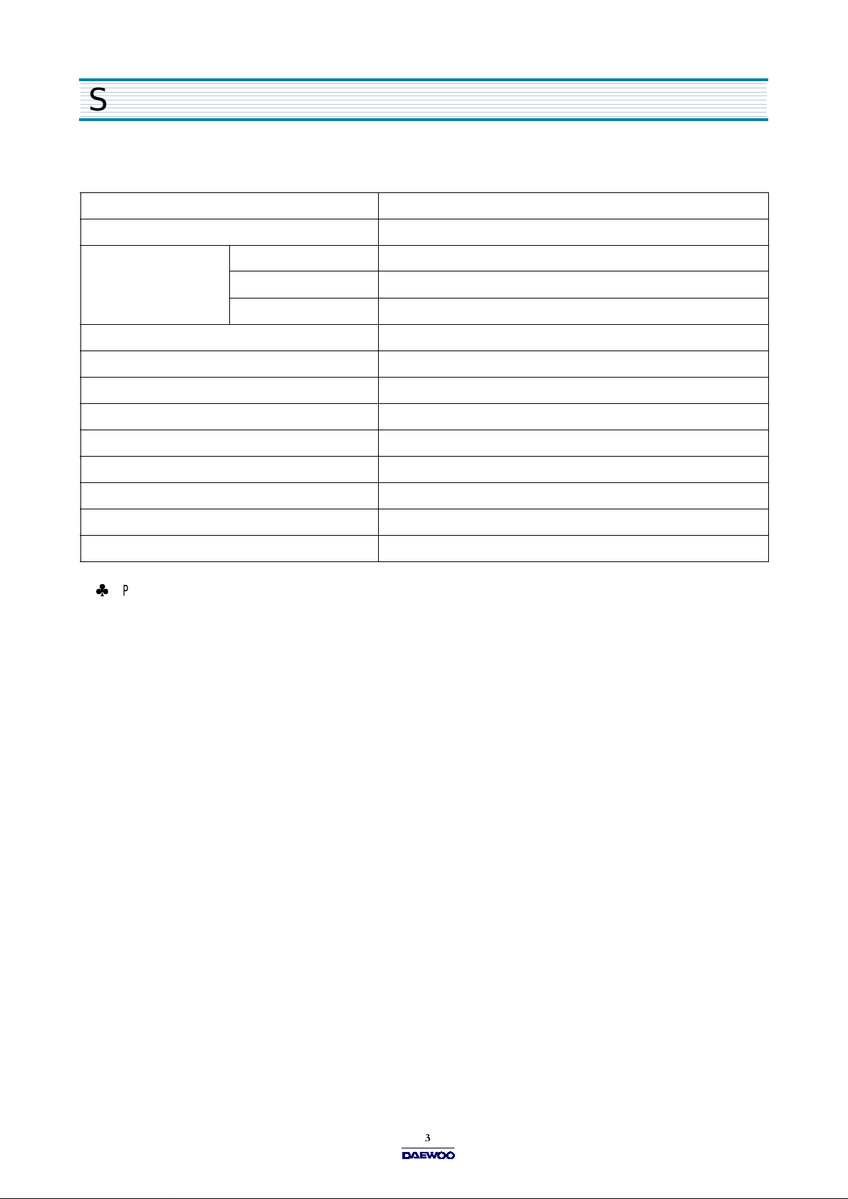
SPECIFICATIONS
MOD EL KOR-161G/161H
POWER SUPPLY 230V~50Hz, SINGLE PHASE WITH EARTH ING
POWER
CONSUMPTION
MICROWAVE ENERGY OUTPUT 1000W
MICROWAVE FREQUENCY 2450MHz
OUTS IDE DIMENSIONS (W X H X D) 589 x 339 x 464 m m (23.2 x 13.3 x 18.3 in.)
CAVITY DIMEN SIONS (W X H X D ) 399 x 274 x 426 m m (15.7 x 10.8 x 16.8 in.)
NET W E IGHT APPRO X. 19.5 Kg ( 43.0 lbs.)
TIME R 99 m in. 99 s ec .
FUNCTION SELECTIONS MICROWAVE
POWER SELECTIONS 10 LEVELS
CAVITY VOLU M E 1.6 C u.Ft.
SPECIFICATIONS ARE SUBJECT TO CHANGE WITHOUT NOTICE.
MICRO WAVE 1400W
GRILL
COMBINATION
Page 3
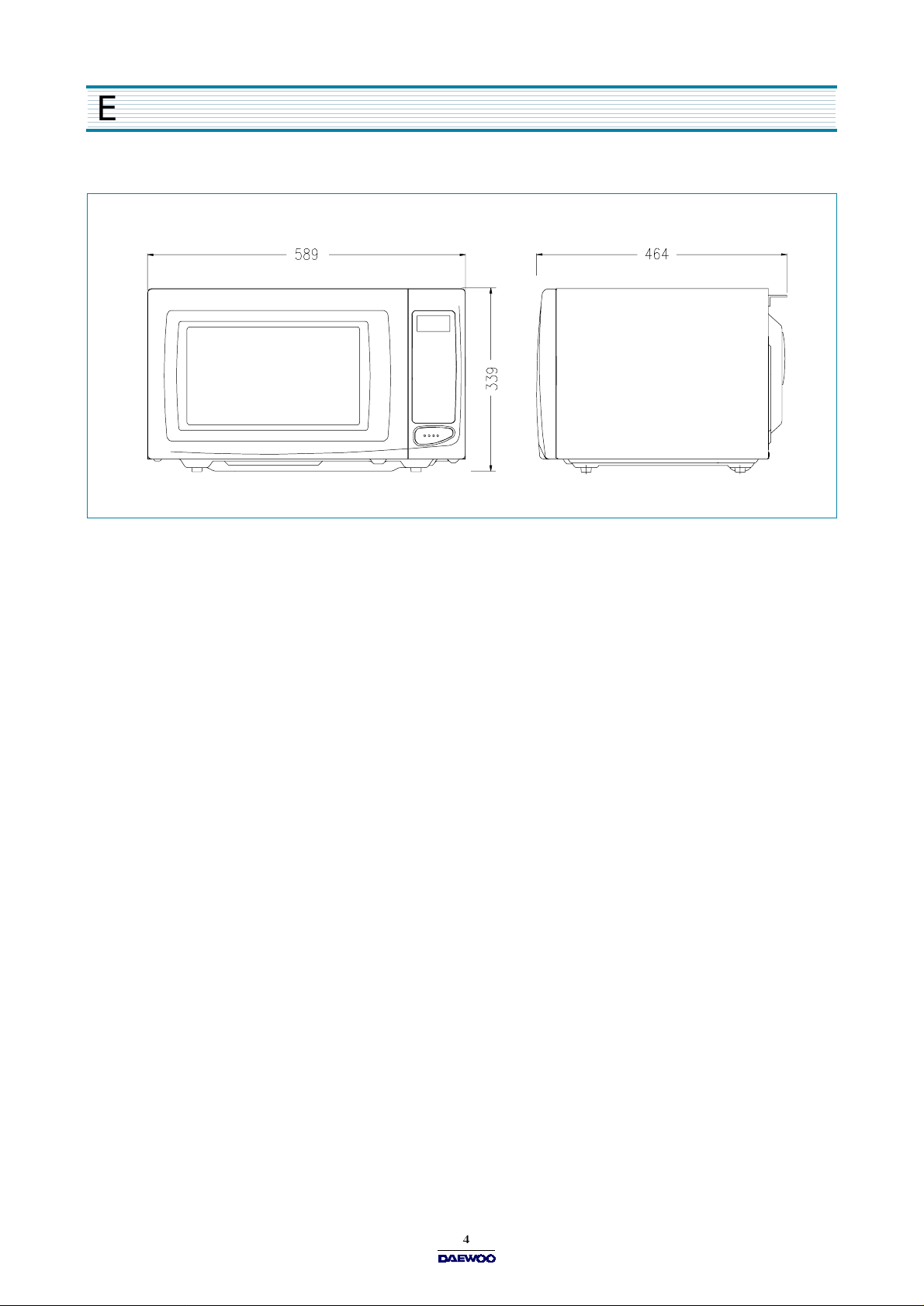
EXTERNAL VIEW
1. OUTER DIMENSION
Page 4
2. FEATURE DIAGRAM
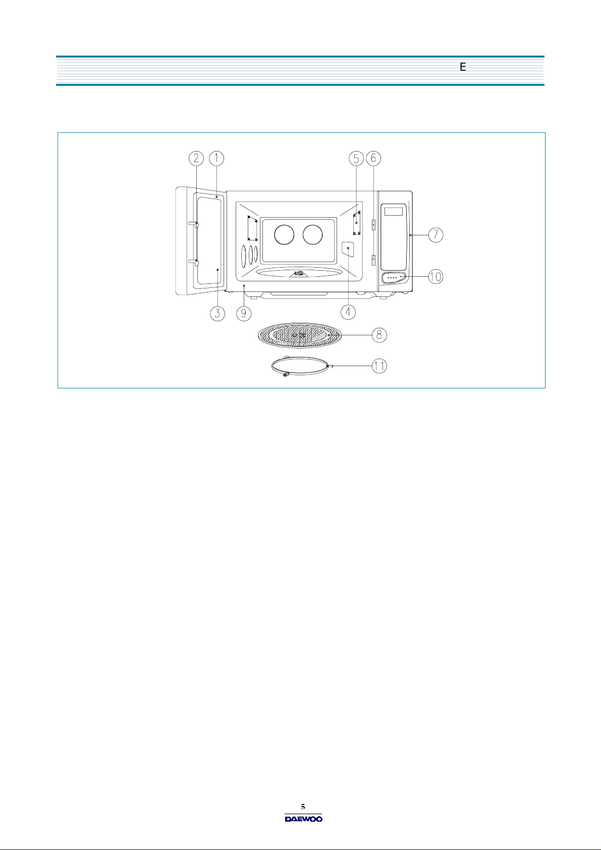
EXTERNAL VIEW
1. DOOR SEAL
Door seal m aintains the microwave within the oven cavity and prevents m icrowave leakage.
2. DOOR HOOK
When door is closed, it will autom atically lock shut. If door is opened while oven is operating, magnetron tube will imm e d iately stop operating.
3. DO OR SCREEN
Allows viewing of food. Microwave cannot pass through perforations in screen.
4. SPATTER SHIELD
Protects the microwave outlet from splashes of cooking foods.
5. O VEN LAMP
Automatically turns on during oven operating.
6. SAFETY INTERLOCK SYSTEM
7. CONTROL PANEL
8. GLASS COOKING TRAY
Made of special heat resistant glass. The tray must always be in proper position before operating. Do not cook food directly
on the tray..
9. O VEN FRON T PLATE
10. DOOR OPENING BUTTON
To open the door, push the door opening button. When door is closed, it will automatically lock shut. If door is opened while
oven is operating, magnetron tube will im m ediately stop operating.
11. ROLLER GUIDE
Supports the glass cooking tray.
Page 5
EXTERNAL VIEW
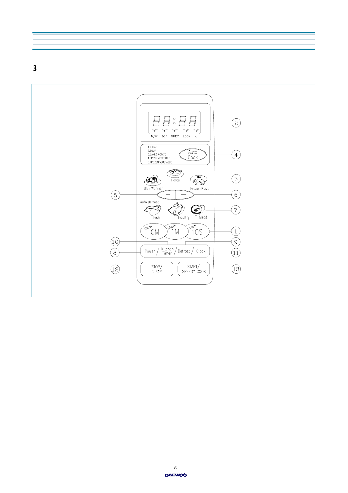
3. CONTROL PANEL
- KOR-161G0S
1. Tim e set pad -
2. Display
3. One touch
4. Auto cook
5. More
6. Less
7. Auto Defrost
8. Power
9. Defrost
10. Kitchen Timer
11. Clock
12. Stop/Clear
13. Start/Speedy cook
- Cooking time, pow er level, indicators and present time are displayed.
- Used to add time to cooking.
- Us ed to remo v e time fr o m c oo k i n g.
- Us ed to s et p ower le v el.
- Us ed to d efrost foo d s.(for time)
- Used to set clock .
Used to set the cooking tim e and the present tim e.
- Used to cook or reheat specific quantities of food.
- Used to cook or reheat.
- Used to defrost foods.(for w eight)
- Used as a minute timer, delay cooking, hold setting after cooking.
- Used to stop the oven operation or to delete the cooking data.
- Used to start the oven and also used to set a reheat tim e.
Page 6

- KOR-161H0S
EXTERNAL VIEW
1. Tim e set pad
2. Display
3. One touch
4. More
5. Less
- Used to add time to cooking.
- Us ed to remo v e time fr o m c oo k i n g.
6. Auto Defrost
7. Power
8. Defrost
9. Kitchen Timer
10. Clock
11. Stop/Clear
- Used to set the cooking tim e and the present time.
- Cooking time, pow er level, indicators and present time are displayed.
- Used to cook or reheat specific quantities of food.
- Used to defrost foods.(for weight)
- Us ed to s et p ower le v el.
- Us ed to d efrost foo d s.(for time)
- Used as a minute tim er, delay cooking, hold setting after cooking.
- Used to set clock.
- Used to stop the oven operation or to delete the cooking data.
12. Start/Speedy cook
- Used to start the oven and also used to set a reheat tim e.
Page 7

INSTALLATI ON
1. Steady, flat location
This microwave oven should be set on a steady, flat surface.
This microwave oven is designed for counter top use only.
2. Leave space behind and side
All air vents should be kept a clearance. If all vents are covered during operation, the oven may overheat and, eventually,
cause failure.
3. Away from radio and TV sets
Poor television reception an d radio interfere nce may result if the o ven is located close to a TV, radio, an tenna or feeder and so on .
Position the oven as far from them as possible.
4. Away from heating appliances and water taps
Keep the oven aw ay from hot air, steam or splash w hen choosing a place to position it, or the insulation might be adversely
affected and breakdowns occur.
5. Power supply
Check your local pow er source.
This m icrowave oven requires a current of approximately 6 amperes, 230 Volts, 50 Hz.
Power supply cord is about 0.8 m eters long.
The voltage used must be the sam e as specified on this oven. U sing a higher voltage may result in a fire or other accident
causing oven damage. Using low voltage will c a u s e s lo w c o ok in g . We a r e n o t re s ponsible for dam age resulting from use
of this oven w ith a voltage of ampere fuse other than those specified.
This appliance is supplied with cable of special type, which, if dam aged, must be repaired w ith cable of sam e type.
Such a cable can be purchased from DAE W O O and must be installed by a Qualified Person.
6. Exam ine the oven after unpacking for any dam age such as:
A m isaligned door, broken door or a dent in cavity.
If any of the above are visible, DO N OT INSTALL, and notify dealer immediately.
7. Do not o p e r a te th e o v e n if it is c old e r than r o o m temp e ra t u re
(This m ay occur during delivery in cold weather.) Allow the oven to become room temperature before operating.
EARTHING INSTRUCTIONS
This appliance m ust be earthed. In the event of an electrical short circuit, earthing reduces the risk of the electric shock by
providing an escape wire for the electric current. This appliance is equipped with a cord having a earthing wire with a earthing
plug. The plug must be plugged into an outlet that is properly installed and earthed.
WARNING
Improper use of the earthing plug can result in a risk of electric shock. Consult a qualified electrician or servicem an if
the earthing instructions are not completely understood, or if doubt exists as to w hether the appliance is properly
earthed, and either : If it is necessary to use an extension cord, use only a 3-wire extension cord that has a 3-blade
earthing plug, and a 3-slot receptacle that w ill accept the plug on the appliance. The m arked rating of the extension
cord should be equal to or greater than the electrical rating of the appliance, or D o not use an extension cord.
Page 8
OPERATIONS AND FUNCTIONS
1. Connect the main lead to an electrical outlet.
2. After placing the food in a suitable container, open the oven door and put it on the glass tray. The glass tray must always
be in place during cooking.
3. Close the door securely.
4. The oven door can be opened at any time during operation by touching the door release button on the control panel.
The oven will automatically shut off. To restart the oven, close the door and then touch START.
5. Each time a pad is touched, a BEEP will sound to acknowledge the touch.
6. The oven automatically cook on full power unless set to a lower power level.
7. The display will show :0 when the oven is plugged in.
8. Time clock returns to the present tim e when the cooking time ends.
9. When the STO P /CLEAR pad is touched during the oven operation, the oven stops cooking and all information retained.
To erase all information (except the present time), touch the STOP/CLEAR pad once more. If the oven door is opened
during the oven operation, all information is retained.
10. If the START pad is touched and the oven does not operate, check the area between the door and door is closed
securely. The oven will not start cooking under the door is com pletely closed or the program has been reset.
Make sure the oven is properly installed and plugged into the electrical outlet.
Wattage output chart
The power level is set by pressing the POW E R pad. The chart shows the display, the power level and the percentage of
power.
Touch POWE R pad. Power level (D isplay) Approximate Percentage of Power
Once P-HI 100 %
Tw ice P-9 0 9 0 %
3 times P-80 80 %
4 times P-70 70 %
5 times P-60 60 %
6 times P-50 50 %
7 times P-40 40 %
8 times P-30 30 %
9 times P-20 20 %
10 times P-10 10 %
11 times P -00 0 %
Page 9
DISASSEMBLY AND ASSEMBLY
- Cautions to be observed when trouble shooting.
Unlike many other appliances, the microwave oven is high-voltage, high-current
equipm ent. It is completely safety during normal operation. H owever, carelessness in servicing the oven can result in an
electric shock or possible danger from a short
circuit. You are asked to observe the following precautions carefully.
1. Alw ays remove the power plug from the outlet before servicing.
2. Use an insulated screwdriver and ware rubber gloves when servicing the high voltage side.
3. D ischarge the high voltage capacitor before touching any oven components or wiring.
1) Check the earthed.
Do not operate on a two-wire extension cord.
The microwave oven is designed to be used
with earthed. It is impera tive, therefore, to makes
sure it is grounded properly before beginning repair work.
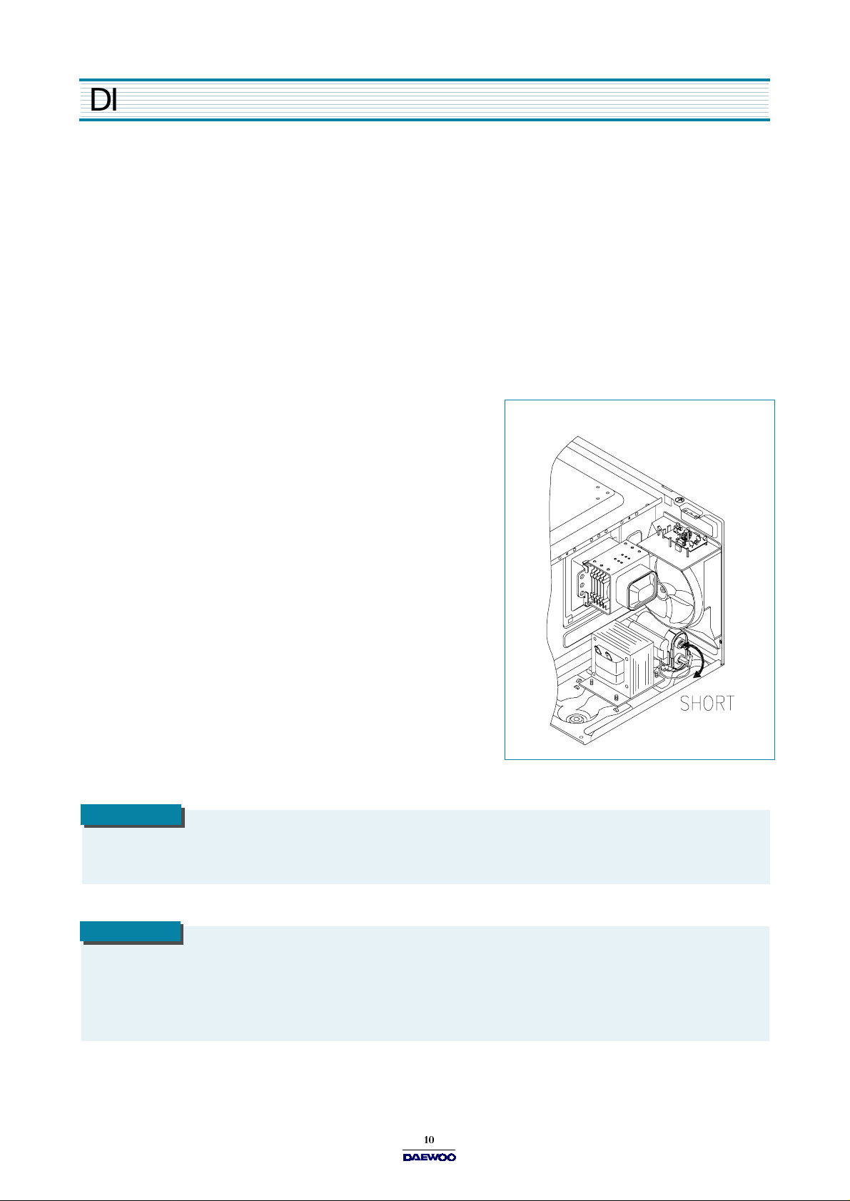
2) Warning about the electric charge in the high voltage capacitor.
For about 30 seconds after the operation stopped and
electric charge remains in the high voltage capacitor.
When replacing or checking parts, short between oven chassis
and the negative high terminal of the high voltage capacitor, by
using a properly insulated screwdriver to discharge.
4. When the 12A fuse is blown out due to the operation of the monitor
switch; replace prim ary interlock switch, secondary interlock switch
and interlock m onitor switch.
5. After repair or replacem ent of parts, make sure that the screws are
properly tightened, and all electrical connections are tightened.
6. Do not operate w ithout cabinet.
CAUTION
Service personnel should rem ove their watches w henever working close to or replacing the magnetron.
CAUTION
When servicing the appliance, need a care of touching or replacing high potential parts because of electrical
shock or ex po sing microvave . Th es e parts are as follows - H V Tran sform er, Ma gn etron, H V C a pa c itor, H V Diode ,
HV Fuse.
Page 10

1. To rem ove cabinet
1) Remove three screws on cabinet back.
2) Push the cabinet backward.
2. To rem ove door assembly
1) Remove two screws wh ich secure the stopper hinge top.
2) Remove the door assembly from top plate of cavity.
3) Reverse the above for reassem bly.
D ISASSEMBLY AND ASSEMBLY
NOTE
After replacing the door assembly, perform a check of correct alignment with the hinge and cavity front plate.
Page 11

D ISASSE MBLY AND ASSE MBLY
3. To rem ove door parts.
REF. NO PART CODE PART NAME DESCRIPTION QTY REMARK
A01 3517005300 BARR IER-SCREEN *O PM M A 1
A02 3512203900 FRAM E DO O R ABS 1
A03 3515202900 STOPPER HINGE *T AS KOR-121M0A 1
A04 3511710500 DOO R PAINTIN G A S KOR-161H0A 1
A05 3517005200 BARR IER-SCREEN *I POLYESTER T0.1 1
A06 3512301800 GASKET DOOR PP 1
A07 3513100900 HOO K POM 1
A08 3515101300 SPRING HO O K PW1 1
1) Remove the gasket door from door plate.
2) Remove the barrier screen inner from door plate.
3) Remove the door fram e from door plate.
4) Remove the stopper hinge top from door plate.
5) Remove the spring and the hook.
6) Remove the barrier screen outer from door frame.
7) Reverse the above steps for reassembly.
Page 12

4. Method to reduce the gap between the door seal and the oven front surface.
1) To reduce gap located on part ‘A’.
Loosen tw o screws on stopper hinge top, and then
push the door to contact the door seal to oven front surface.
Tighten two screw s.
2) To reduce gap located on part ‘B’.
Loosen two screws on stopper hinge under, and then
push the door to contact the door seal to oven front surface.
Tighten two screw s.
3) To reduce gap located on part ‘C’.
Loosen a screw on interlock switch assembly located top of oven body.
Draw the inte rlock switch assembly inward as possible to engage with hook on the door bottom.
Tighten a screw.
D ISASSEMBLY AND ASSEMBLY
4) To reduce gap located on part ‘D’.
Loosen a screw on interlock switch assembly located bottom of oven body.
and (4) are same as step (3).
NOTE
A small gap m ay be acceptable if the microw ave leakage does not exceed 4mW/cm2.
Page 13

D ISASSE MBLY AND ASSE MBLY
5. To rem ove control panel parts.
REF.NO PART CODE PART NAME DESCRIPTION QTY REMARK
B01 3518521800 SW ITCH M EM BR AN E KOR -161G0S 1
3518521810 SW ITCH ME M BR ANE KO R-161H0S 1
B02 3516719100 CONTROL-PANEL ABS 1
B03 3514317610 PC B MAIN AS KOR-161H0S 1
B04 7122401211 SC REW TAPPING T2S TRS 4x12 MFZN 4
B05 3513702800 LEVER DO OR O PEN ABS XR -401 H-2938 1
B06 441G430171 S PR ING BUTTO N SW P D IA 0.7 1
B07 3516907100 BU TTON DO OR O PEN ABS 1
1) Remove the screw which secure the control panel, push up two snap fits and draw forward the control panel assembly.
2) Remove the door open lever from the control panel.
3) Remove four screw s which secure the PCB assembly to control panel.
4) Disconnect membrane tail from the connector of the P CB assembly.
5) Detach membrane from the control panel.
6) Remove door open button and button spring from the control panel.
7) Reverse the above steps for reassembly.
Page 14

6. To rem ove high voltage capacitor.
1) Remove a screw which secure the grounding ring term inal
of the H.V.diode and the capacitor holder.
2) Remove the H.V. diode from the capacitor holder.
3) Reverse the above steps for reassembly.
High voltage circuit wiring
D ISASSEMBLY AND ASSEMBLY
7. To rem ove magnetron.
1) Remove a screw which secure the magnetron.
2) Remove the magnetron.
3) Reverse the above steps for reassembly.
NOTE
Never install the magnetron without the m etallic gasket plate which is packed with each magnetron to prevent
microw ave leakage. W henever repair work is carried out on magnetron, check the microwave leakage. It shall
not exceed 4m W /cm
2
for a fully assembled oven with door normally closed.
Page 15

D ISASSE MBLY AND ASSE MBLY
8. To remove wind guide assembly.
1) Remove a screw for earthing.
2) Remove the noise filter from the wind guide.
3) Remove a screw which secure the wind guide assembly.
4) Draw forward the wind guide assembly.
5) Pull the fan from the m otor shaft.
6) Remove two screws which secure the motor shaded pole.
7) Remove the motor shaded pole.
8) Reverse the above steps for reassembly.
9. To rem ove H.V.transformer.
1) Remove four screws holding the H .V.transform er.
2) Remove the H.V.transformer.
3) Reverse the above steps for reassembly.
Page 16

INTER L OC K MECHANISM AND ADJUSTMENT
The door lock mechanism is a device which has been specially designed to completely eliminate microwave radiation when
the door is opened during operation, and thus to perfectly prevent the danger resulting from the leakage of microw ave.
(1) P rima r y interlock switch
Wh e n th e d o or is c l o sed, the h oo k loc ks th e oven door. If the door is n ot c los e d p rop erly, th e o v en will n ot o pe r ate .
When the door is closed, the hook pushes the button of the microswitch. Then the button of the prim ary in terlock switch
bring it un der O N condition.
(2) Secondary interlock switch and interlock monitor switch
When the door is closed, the hook pushes the lock lever downward. The lock lever presses the button of the interlock
monitor switch to bring it under NO condition and presses the button of the secondary interlock switch to bring it under
O N co n dit ion.
ADJUSTME NT
Interlock monitor switch
W hen the door is closed, the interlock m onitor switch should be changed(NO condition) before other switches are closed.
W hen the door is opened, the interlock monitor switch should be changed(NC condition) after other switches are opened.
(3) Ad jus tme n t ste p s
a) Loosen the two mounting screws.
b) Adjust interlock switch assembly position.
c) Make sure that lock lever m oves smoothly after adjustment is completed.
d) Tighten completely tw o m ounting screws.
NOTE
Microwave em ission test should be performed after adjusting interlock mechanism . If the microwave em ission exceed
4mW/cm
2
, readjust interlock m echanism.
Page 17

TROUBLE SHOOTING GUIDE
Following the procedure below to check if the oven is defective or not.
1) C heck earthing before trouble checking.
2) Be careful of the high voltage circuit.
3) Discharge the high voltage capacitor.
4) When checking the continuity of the switches, fuse or high voltage transformer, disconnect one lead wire from these parts
and ch ec k co ntinuity with the AC plug rem o ve d. To do otherwise may resu lt in a false reading or damag e to you r m e ter.
NOTE
W hen electric parts are checked, be sure the pow er cord is not inserted the wall outlet.
Check wire harness, wiring and connected of the terminals and power cord before check the parts listed below.
(TR OUBLE 1 )
CONDITION
Fuse blow s.
Ove n do es no t ope rate at all : any inpu ts can no t be ac cepted .
CHECK RESULT CAUSE REMEDY
Check continuity of
inte rlock mon itor switch
with door closed
(COM NC)
Check continuity of both
prim ary and secondary
interlock switch with door
colosed
Check continuity of primary
inte rlock switch contact
with door partially open
until interlock m onitor switch
contact close
(COM<->NO )
Continuity
No C ontinuity
No C ontinuity
No C ontinuity
Continuity
Continuity
Malfunction
of interlock
monitor
switch
Malfunction of
inte rlo ck switch
Shorted contacts
of primary
inte rlo ck switch.
Replace
NOTE 1
Replace
NOTE 1
Replace
NOTE 1
Check continuity of
prim ary winding of low
voltage transformer
Disconnect high voltage
fuse and operate the unit
0 infinite
or
Ω
Approx.
150~310
(norm al)
Fuse again
blows
Defective low
voltage
transformer
Defective high
voltage transformer
Replace
Replace
Page 18

TROUBLE SHOOTING GUIDE
CONDITION
Outlet has
proper voltage
Fuse does not
blow.
CHECK RESULT CAUSE REMEDY
Check continuity of
magn etron
Check continuity of
noise filter board
Check continuity of
power supply cord
No
Continuity
No
Continuity
No
Continuity
Normal
Defective
magn etron
Defective line
filter board
Open pow er
supply cord
Defective touch
control circuit
NOTE
All these switches must be replaced at the sam e time, please refer to “Interlock M echanism And Adjustm ent”.
( TRO UB LE 2 )
Display shows all figures selected, but oven does not start cooking, even though desired program and tim e
are set and start pad is tapped.
Replace
Replace
Replace
Adjust
CONDITION
Turn table
m oto r, and
oven lamp do
not turn on
CHECK RESULT CAUSE REMEDY
Check continuity of
primary interlock sw itch
Check continuity of
secondary interlock switch
Che ck D .C. voltage
being supplied to
RELAY (RY2) coil
No
Continuity
No
Continuity
0 V
Approx
15 VDC
Malfunction
of primary
inte rlo ck switch
Malfunction
of secondary
inte rlo ck switch
Defective
touch control
circu it
Faulty
contacts of
RELAY
(RY2) or open
relay coil
Adjust or
Replace
Adjust or
Replace
Replace
Replace
Page 19

TROUBLE SHOOTING GUIDE
(
TROUBLE 3 )
C O ND IT ION
No microwave
oscillation
N o mic r owa ve o sc illation e ve n tho u gh fa n moto r r ota t e s.
CHECK RESULT
Che ck contin uity of high
voltage fuse
Rep la ce high volta ge fuse
Che ck contin uity of high
voltage cap acitor
terminals with wires
removed
Che ck contin uity of high
vo lt age re c tif ie r in
forward and ba ckward
direction with D C
megger
Con nec t m egger leads to
mag netro n te rminal and
mag netro n body
No Continuity
Continuity
Continuity in
backward
direction
Continuity
CAUSE
Defective
high voltage
tran sform er
Defective
high voltage
rectifier
Defective
magn etron
REMEDY
Replace
Replace
Replace
Ch eck resistance o f
primary and secondary
coil of high voltage
transformer
Ch e ck co ntinuity of
magnetron with wires
removed
Ch e ck co ntinuity of
filament terminal of high
voltage transfo rmer
Check D.C. voltage
being supplie d to
RELAY (RY1) coil
or
0 Ω
No
Continuity
No
Continuity
0 V
Approx
15 VDC
Defective
high voltage
tran sform er
Defective
magn etron
Defective
high voltage
tran sform er
Defective
touch control
circuit
Faulty
contacts or
RELAY
(RY1) or o pen
re la y c o il
Replace
Replace
Replace
Replace
Replace
Page 20

TROUBLE SHOOTING GUIDE
CONDITION
Replace
control box
sub-assembly
Replace the
Malfunction
( TROUBLE 4 )
The following visual conditions indicate a probable defective touch control circuit or membrane switch
assembly
1. Incomplete segments,
1) Segments missing.
2) Partical segments missing.
3) Digit flickering other than norma l display slight
flickering.
4) “ : 0 ” does not display when power is on.
2. A distinct change in the diplay are not on when they
numbers is the display.
3. One or m ore digits in the diplay are not on when they should be.
4. Display indicates a number different from one touched.
5. Specific num bers (for example 2 or 3) will not display when the panel is touched.
6. Display does not count down or up w ith time cooking or clock operation.
7. Oven is programmable and cooks normally but no display shows.
8. Display obviously jumps in time w hile counting dow n.
9. Display counts down noticeably too fast while cooking.
10. Display does not show the time of day when clear pad is touched.
11. Oven lamp and turntable m otor do not stop although cooking is finished. Check if the RE LAY 2 contacts close if they are
close, replace touch control circuit.
CHECK RESULT CAUSE REMEDY
Display does
not show
program ming
at all, even if
keyboard is
touched.
Check each pad for
continuity of the
mem brane keyboard
for the following
keyboard check
procedure
Normal
Abnormal
of touch
control circuit
of control box
sub-assembly
Malfunction of
the mem brane
keyboard
membrane
keyborad
NOTE
Before following the particular steps listed above in the trouble shooting guide for the membrane keyborad’s, failure,
please check for the continuity of each wire-harness between the m embrane keyboard and P.C.B. assembly.
Page 21

ME ASUREME NT AND TEST
1. MEASUREMENT OF THE MICROWAVE POWER OUTPUT
Microwave output power can be checked by indirectly m easuring the temperature rise of a certain amount of water exposed
to the microwave as directed below.
PROCEDURE
1. Microwave power output measurement is made wit the m icrow ave oven supplied at rated voltage and operated at its
maximum m icrowave pow er setting with a load of 1000 ± 5cc of potable water.
2. T h e w a te r is co nta in e d in a cy lin d ric a l b o ro s ilic a te g la s s v e s se l h a v in g a ma x imu m ma te r ia l th ic kn e s s of 3 mm and an
outside diameter of approximately 190 m m .
3. The oven and the empty vessel are at ambient tem perature prior to the start of the test. The initial temperature of the
water is 10 ± 2 °C (50 ± 3.6 °F). It is measured imm ediately before the water is added to the vessel. After addition of
the
water to the vessel, the load is immediately placed on the center of the shelf, w hich is in the lowest normal position.
4. Microwave power is sw itched on.
5. Heating time should be exactly A seconds.
(Refer to table as following)
Heating time is m easured while the
microw ave generator is operating at
full power. The filament heat-up time
for magnetron is not included.
6. The initial and final temperature of water is selected
so that the maximum difference between the ambient
and final w ater temperature is 5K.
7. The microwave power output P in watts is calculated
from the following formula:
P = 4187 X T
T is difference between initial and ending temperature.
t is the heating tim e.
The power measured should be B (Refer to SPECIFICATIONS ) W ± 10.0 %.
CAUTION
1. W ater load should be m easured exactly to 1 liters.
2. Input power voltage should be exactly specified voltage (Refer to SPECIFICAT IONS).
3. A m bient temperature should be 20
Heating time for power output:
A (second) 70 64 60 56 52 49 47 44 42 40 38
B (W) 600 650 700 750 800 850 900 950 1000 1050 1100
± 2°C (68 ± 3.6 °F)
Page 22

MEASUR E MENT AND TEST
2. MICROWAVE RADIATION TEST
CAUTION
1. Make sure to check the microwave leakage before and after repair of adjustment.
2. Always start m easuring of an unknown field to assure safety for operating personnel from microw ave energy.
3. Do not place your hands into any suspected m icrowave radiation field unless the safe density level is known.
4. Care should be taken not to place the eyes in direct line with the source of microw ave energy.
5. Slowly approach the unit under test until the radiometer reads an appreciable m icrow ave leakage from the unit
under the test.
PROCEDURE
1. Prepare Microwave Energy Survey Meter,
600cc glass beaker, and glass thermometer
100°C (212°F ).
2. Pour 275cc ±15cc of tap water initially at 20 ± 5 ° C
(68 ± 9°F) in the 600 cc glass beaker with an inside
diameter of approx. 95 m m(3.5 in.).
3. Place it at the center of the tray and set it in a cavity.
4. Close the door and operate the oven.
5. Measure the leakage by using Microwave Energy
Survey M eter with dual ranges, set to 2450M H z.
1) Measured radiation leakage must not exceed the
value prescribed below. Leakage for a fully assem bled
oven with door normally closed must be less than 4mW /cm2.
2) When measuring the leakage, always use the 5 cm (2 in.) space cone with probe. Hold the probe perpendicular to the
cabinet and door. Place the space cone of the probe on the door, cabinet, doo r seem, door viewing screen, the exhau st
air vents and the suction air vents.
3) Measuring should be in a counter-clockwise direction at a rate of 1 in./sec. If the leakage of the cabinet door seem is
unknown, m ove the probe m ore slowly.
4) When measuring near a corner of the door, keep the probe perpendicular to the areas making sure the probe end at
the base of the cone does not get closer than 2 in. from any m etal. If it does not, erroneous reading m ay result.
Page 23

MEASUR E MENT AND TEST
3. COMPONENT TEST PROCEDURE
High voltage is present at the high voltage terminal of the high voltage transform er during any cooking cycle.
It is neither necessary nor advisable to attempt m easurement of the high voltage.
Before touching any oven components or wiring, always unplug the oven from its power source and discharge the capacitor.
1. H igh voltage transformer
1) Remove connections from the transformer terminals and check continuity.
2) Normal readings should be as follows :
Secondary w inding ... Approx. 110 ±10%
once the capacitor charged.
Filament winding ... Approx. 0
Prim ary winding ... Approx. 1
2. H igh voltage capacitor
1) Check continuity of capacitor with meter on the highest OHM scale.
2) A normal capa cito r will s how cont inui ty fo r a s h or t t ime, and then indicate 10M
3) A shorted capacitor will show continuous continuity.
4) An open capacitor will show constant 10M.
5) Resistance betw een each term inal and chassis should be infinite.
3. H igh voltage diode
1) Isolate the diode from the circuit by disconnecting the leads.
2) With the ohm meter set on the highest resistance scale measure the resistance across the diode term inals. Reverse
the m eter leads and again observe the resistance reading. Meter with 6V, 9V or higher voltage batteries should be
used to check the front-back resistance of the diode, otherwise an infinite resistance may be read in both directions. A
normal diode's resistance will be infinite in one direction and several hundred k
in the other direction.
4. Magnetron
For complete magnetron diagnosis, refer to “Measurement of the Microwave Power Output " Continuity checks can only
indicate and open filament or a shorted magnetron. To diagnose for an open filament or a shorted magnetron,
1) Isolate m agnetron from the circuit by disconnecting the leads.
2) A continuity check across m agnetron filament terminals should indicate 0.1
or less.
3) A continuity check between each filament terminal and magnetron case should read open.
5. Fuse
If the fuse in the primary and monitor switch circuit is blown when the door is opened, check the primary and monitor
switch before replacing the blown fuse. In case the fuse is blown by an improper switch operation, replace the defective
switch and fuse at the same tim e. Replace just the fuse if the switches operate normally.
Page 24

WIRING DIAGR AM
Page 25

PRINTED CIRCUIT BOARD
1. CIRCUIT CHECK PROCEDURE
1. Low voltage transformer check
The low voltage transform er is located on the P.C.B.
Measuring condition: Input voltage: 230 V / Frequency: 50Hz
Terminal Voltage LOAD NO LO AD
4 - 7 AC 12.6 V AC 14.7 V
NOTE
1. R efer to C ircuit Diagram (point 4).
2. Secondary side voltage of the low voltage transformer changes in proportion to fluctuation of pow er source voltage.
3. The allow able tolerance of the secondary voltage is within 5% of nominal voltage.
2. Voltage Check
- Key check point
NO CHECK POINT REMARK
1 IC1 PIN 2,21,30,34 -5VDC
2IC1 PIN 35
T : 20 ms( 50Hz)
3 IC1 PIN 31 OR 32
T : 250 ns(4MHz )
- Check method
NO MEASURE POINT WAVE FORM REMEDY REMARK
1 MP1 DC -5V± 0.25V Replace VL1, EC1 NO LOAD
2 MP2 DC -12V± 2.0V Replace EC 2, D12,13,14 NO LOAD
NOTE
Each measure point must be measured with GND points.
Page 26

PRINTED CIRCUIT BOARD
MP1
MP2
Measure Point
Page 27

PRINTED CIRCUIT BOARD
3. When there is no microwave oscillation
1) When touching
START
pad, oven lamp does not turn on.
Fan motor do not rotate, but cook indicator in display com es on.
Cause :
RELAY 2
does not operate. ref e r to Cir cui t Dia gr a m ( Poin t 3)
- Check method
PO INT
STATE
RELAY 2
RELAY 2
2) When touching
ON - 5VDC GND
OFF GND - 12VDC
START
pad, oven lamp turns on.
A B
Fan motor and turntable rotate and cook indicator in display comes on.
Cause :
RELAY 1
does not operate. ref e r to Cir cui t Dia gr a m ( Poin t 2 )
- Check method
P OINT
STATE
RELAY 1
RELAY 1
O N -5V DC GN D
OFF GND -12VDC
A B
4. When the door is opened during operation, the count down timer does not stop.
refer to Circuit Diagram ( Point 1 )
- Check method
POINT
STATE
1) DOOR OPEN OPEN -5VDC
2) DOOR CLOSED CLOSE GND
CHECK NO METHOD REM EDY
1
Ch eck the stage (ON,OFF ) of the se condary interlock switch by resistanc e
me asurement.
A B
Replace secondary interlock switch.
5. When the digital clock does not operate properly.
refer to Circuit Dia gram ( Point 5 )
POINT WAVE FORM
A T: 20 ms(5 0 Hz )
If clock does not keep exact time, you must check resistor R15,16, zener diodeZD1.
Page 28

2. PCB CIRCUIT DIAGRAM
PRINTED CIRCUIT BOARD
Page 29

PRINTED CIRCUIT BOARD
3. P.C.B. LOCATION NO.
NO NAME SYMBOL SPEC IFICAT ION PART CODE Q'TY
1 B UZZER BZ1 B M-20K 3515600100 1
2 C ARR AY CA1 7P(6) 102 M 50V CN6X B-102M 1
3 C APACITOR ELEC EC1 16V RSS 100uF CEXF1C101V 1
4 C APACITOR ELEC EC2 25V RSS 1000uF CEXF1E102V 1
5 C ON NE CTOR WAF ER CN1 YW396-02AV 3519150520 1
6 C ON NE CTOR WAF ER CN2 YW396-05AV 3519150510 1
7 C ON NE CTOR WAF ER CN3 FCZ254-11 441M367160 1
8 D IODE R ECTIFY D1~6,9~12 1N4148 DZN4148--- 10
9 D IODE R ECTIFY D13,14 1N4002A DZN4002A-- 2
10 DIODE ZENER ZD1 MTZ 5.1VB 1/2W DZTZ5R1B-- 1
11 DIODE ZENER ZD2 MTZ 3.9VB 1/2W DZTZ3R9B-- 1
12 LE D DISPLAY DP1 DDG -631H DDDG631H-- 1
13 P CB M A IN M158 81.5X139.9 3514315410 1
14 R ARR AY RA1 7P(6) 1/8 100K J R A-87X104J 1
15 R ESISTOR R1~R7 1/6W 330 5% RD -AZ331J- 7
16 R ESISTOR R8,10,12,14,22 1/6W 1K 5% RD-AZ102J- 5
17 R ESISTOR R11,20,21 1/6W 100K 5% RD-AZ104J- 3
18 R ESISTOR R13 1/6W 100 5% RD-AZ101J- 1
19 R ESISTOR R15~17 1/6W 10K 5% RD-AZ103J- 3
20 R ESISTOR R18 1/6W 1M 5% R D-AZ105J- 1
21 R ESISTOR R19 1/4W 51 5% RD-4Z510J- 1
22 R EG ULATOR VL1 MC7905C 1MC 7905C-- 1
23 T RANS ISTOR Q1~5,9~11 KRA-102M T ZRA 102M-- 8
24 T RAN SISTOR Q6 KTA-1270Y TZTA1270Y- 1
25 TRANS POWER LVT1 DMR-631FS 5EPV035303 1
26 W IRE COPPER J1-J21 1/0.52 TIN COATING 85801052GY 21
27 W IRE COPPER SJ2,3,5 1/0.52 TIN COATING 85801052GY 3
28 IC MICO M IC1 TMP47C 440BN 13G S631GH 0 1
29 RESONATO R CERA CR1 KBR-4.0MSTF 5PKBR40MKS 1
30 S W RE LAY RY1 G5G -1A DC12V 5SC 0101121 1
31 S W RE LAY RY2 G5B-1 DC12V 5S C0101110 1
32 C APACITOR CERA C6 102 50V Z AXIAL CCZB1H102K 1
33 C APACITOR CERA C1~5,C7 104 50V Z AXIAL CCZ F1H104Z 6
Page 30

EXPLODED VIEW AND PARTS LIST
1. DOOR ASSEMBLY
Refer to Disassem bly and assembly.
2. CONTROL PANEL ASSEMBLY
Refer to Disassem bly and assembly.
3. TOTAL ASSEMBLY
 Loading...