

Page 1

Service Manual
Side By Side Refrigerator
Model: FRS-2021
DAEWOO ELECTRONICS CORP.
S/M No. : FRS2021100
✔
Caution
: In this Manual, some parts can be changed for improving, their
performance without notice in the parts list. So, if you need the
latest parts information,please refer to PPL(Parts Price List) in
Service Information Center (http://svc.dwe.co.kr).
FRS-2041
FRS-2421
FRS-2441
http://svc.dwe.co.kr Nov. 2003
There was an engineering change in Side By Side Refrigerators.
The function that controls Top Hinge's left and right side was removed.
As a result, "Installation Guide" was modified and "Screw Machine" was deleted in service manual.
This change took effect on
Nov. 11th, 2003.
So please refer to the revision service manual for the SBS models produced after
Nov. 11th, 2003
.
! Notice !
Page 2

TABLE OF CONTENTS
1. EXTERNAL VIEWS
----------------------------------------
3
1-1. EXTERNAL SIZE
----------------------------------------
3
1-2. NAME OF PARTS
----------------------------------------
7
2. SPECIFICATIONS
----------------------------------------
9
2-1. OUTLINE
----------------------------------------
9
2-2. ELECTRIC PARTS
----------------------------------------
10
2-3. POWER CORD
----------------------------------------
13
2-4. DOOR COLOR
----------------------------------------
14
3. OPERATIONS AND FUNCTIONS
----------------------------------------
15
4. DIAGRAM
4-1. WIRING DIRGRAM
----------------------------------------
41
4-2. CIRCUIT DIAGRAM
----------------------------------------
42
4-3. AIR FIOW DIAGRAM
----------------------------------------
44
4-4. REFRIGERANT CYCLE DIAGRAM
----------------------------------------
45
5. DISASSEMBLY AND ASSEMBLY
----------------------------------------
46
7. EXPLODED VIEW AND PART LIST
----------------------------------------
60
7-1. TOTAL EXPLODED VIEW
----------------------------------------
60
7-2. TOTAL PART LIST
----------------------------------------
68
SAFETY AND PRECAUTIONS
1) For starters, be sure to check any chances of the leakage of electricity
2) You could handle a part in the vicinity of electricity after unplugging
3) You should put on rubber glovers to prevent an electric shock on operation test
4) Make sure the rated current, voltage, capacity before using an instrument
5) Keep your wet hands away from the metal goods in the freezer compartment not to be frostbitten
6) Be careful not to let water to permeate the electric part in the machine room
7) with the door open during your working, you might be damaged by that door
8) You should give a tilt to the refrigerator for your safe after removing the breakable
goods inside the refrigerator
9) You'd better use cotton gloves if you fix it up around the evaporator
6. INSTALLATION GUIDE
----------------------------------------
54
----------------------------------------
41
Page 3
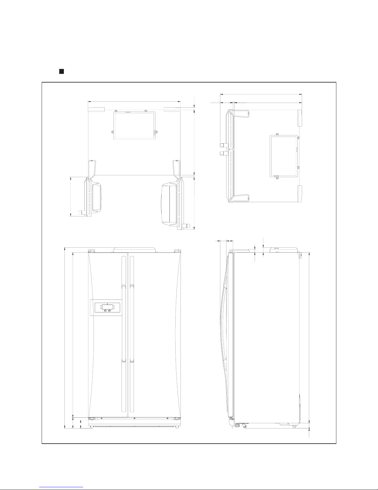
1. EXTERNAL VIEWS
1-1. EXTERNAL SIZE
FRS-2021
-
- 3
-
816
676.5
12.5
127
25.5
651
20
925
524
391
1808
1650
108
82.5
3.5
47.5
1707
50
61
66
30
Page 4
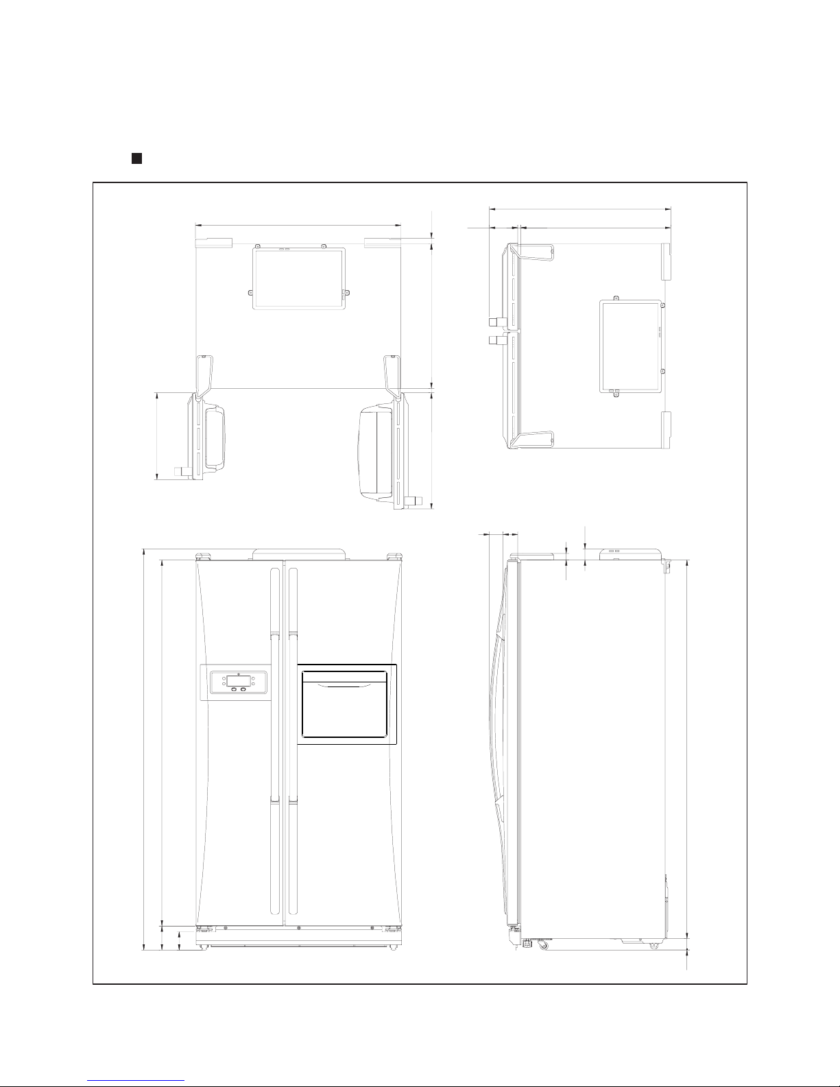
FRS-2041
-
- 4
-
816
676.5
12.5
127
25.5
651
20
925
524
391
1808
1650
108
82.5
3.5
47.5
1707
50
61
66
30
Page 5
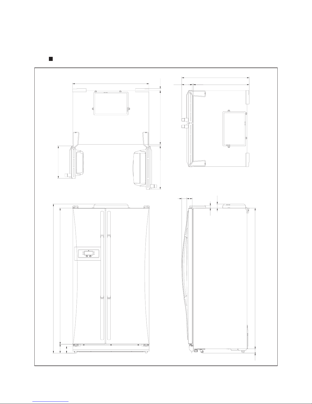
FRS-2421
-
- 5
-
896
756.5
12.5
127
25.5
731
20
925
524
391
1808
1650
108
82.5
3.5
47.5
1707
50
61
66
30
Page 6
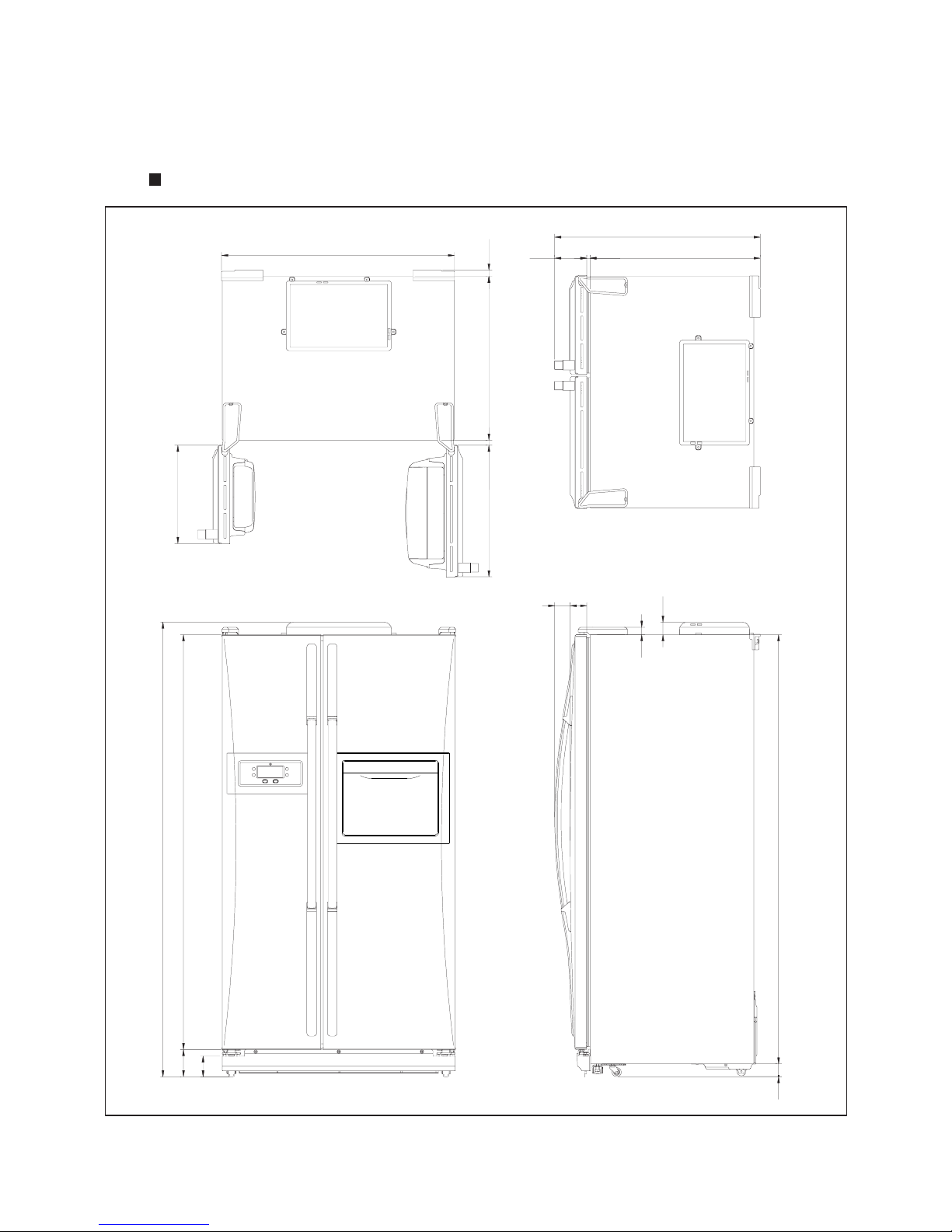
FRS-2441
-
- 6
-
896
756.5
12.5
127
25.5
731
20
925
524
391
1808
1650
108
82.5
3.5
47.5
1707
50
61
66
30
Page 7
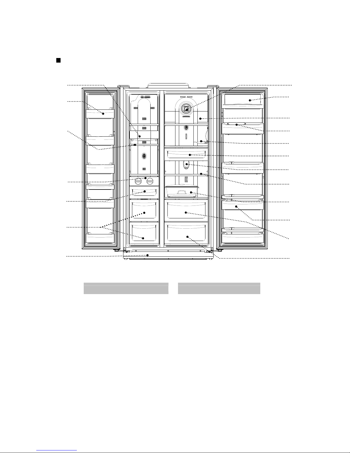
Freezer Compartment Refrigerator Compartment
1. Freezer Light 9. Deodorizer
2. Freezer Pockets 10. Dairy Pocket
3. Freezer Shelves 11. Refrigerator Top Light
5. Ice Cubes Maker 12. Refrigerator Small Pocket
6. Ice Cubes Case 13. Foldaway Wine Support
7. Freezer Case 14. Chilled Case
8. Front Cover 15. Refrigerator Bottom Light
16. Refrigerator Shelves
17. Egg Case
18. Refrigerator Pockets
19. Vegetables Case
20. Fruits Case
1
2 3 5 6 7 8 9
11
12
13
14
15
16
17
18
19
20
10
1-2. NAME OF PARTS
FRS-2021 / FRS-2421
- 7 -
Page 8
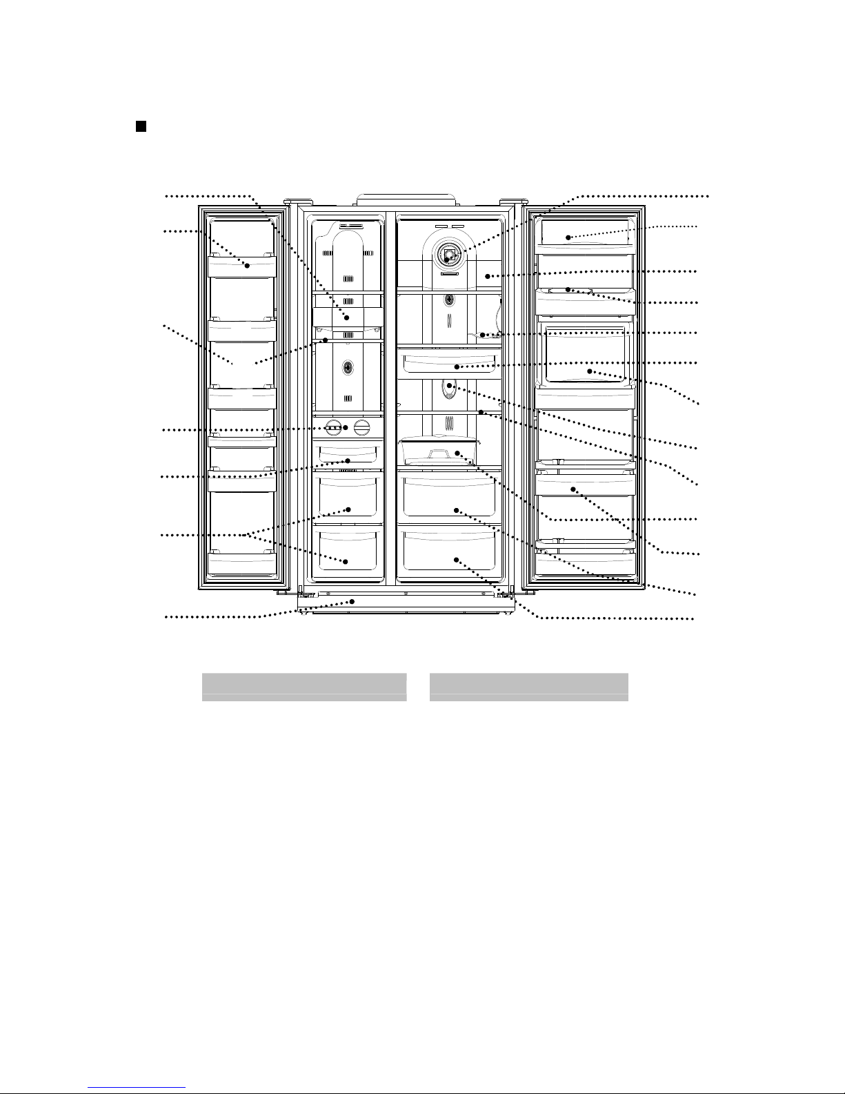
Freezer Compartment Refrigerator Compartment
1. Freezer Light 9. Deodorizer
2. Freezer Pockets 10. Diary Pocket
3. Freezer Shelves 11. Refrigerator Top Light
5. Ice Cubes Maker 12. Refrigerator Small Pocket
6. Ice Cubes Case 13. Foldaway Wine Support
7. Freezer Cases 14. Chilled Case
8. Front Cover 15. Refreshment (Home-Bar) Pocket
16. Refrigerator Bottom Light
17. Refrigerator Shelves
18. Egg Case
19. Refrigerator Pockets
20. Vegetables Case
21. Fruits Case
1
2 3 5 6 7 8 9
11
12
13
14
16
17
18
19
20
21
15
10
FRS-2041 / FRS-2441
- 8 -
Page 9
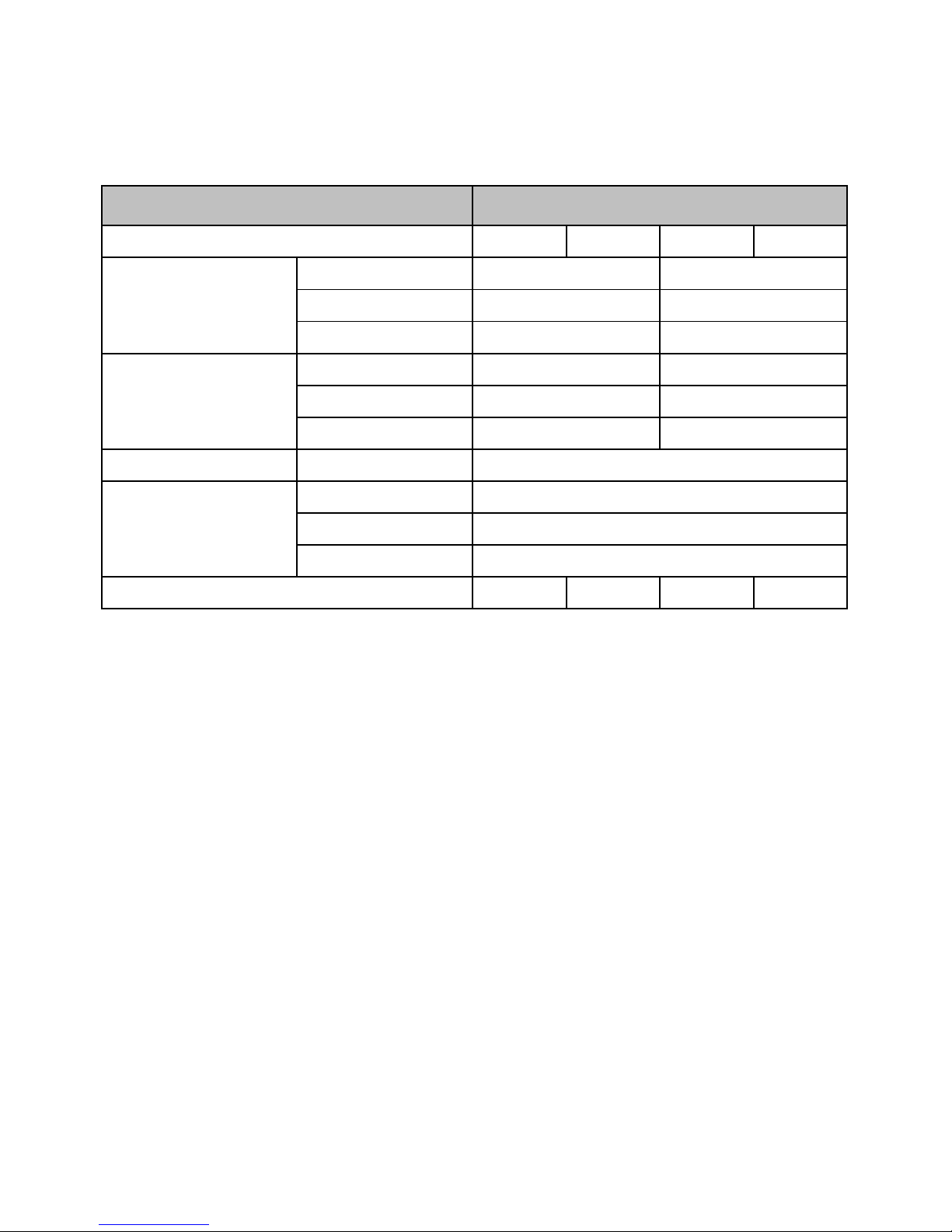
2. SPECIFICATIONS
2-1. OUTLINE
FRS-2021 FRS-2041 FRS-2421 FRS-2441
FREEZER
REFRIGERATOR
TOTAL
WIDTH
DEPTH
HEIGHT
REFRIGENT R134a
COOLING SYSTEM
DEFROST SYSTEM
DEFORST CONTROL
112 114 120 122
EXTERNAL
DIMENSION (mm)
COOLING & CONTROL
SYSTEM
NET WEIGHT (kg)
925
896
1808
256
430
686
USABLE CAPACITY (L)
Fan Cooling System
Fin Evaporator Forced
Automatic Start & Stop
150/190
215
370
CONTENTS
MODEL NAME
DIVISION
585
925
816
1808
- 9 -
Page 10
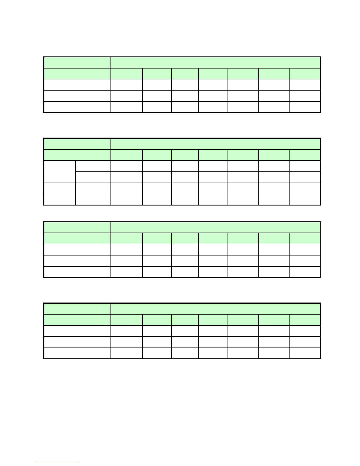
2-2 ELECTRIC PARTS
1) COMPRESSOR
REFRIGERANT R134a
VOLTAGE ( V/HZ) 100 /50,60 110 / 60 115,120/60 127/60 220 / 60 220 ~240/50
230 /50
(
EUROP
)
COMP MODEL
X HBL27YG-3 X HCL27YG-2 HPL27YG-4A HPL30YG-5 DK190Q-L2U
X 3952127R30 X 3957127R20 3956127R40 395S130R50 3956190D50
STARTING TYPE
X CSR X CSIR RSCR RSCR RSCR
2) RELAY
REFRIGERANT R134a
VOLTAGE ( V/HZ) 100 /50,60 110 / 60 115,120/60 127/60 220 / 60 220~240 / 50 230 / 50
TYPE NAME
X 783SHB X 801SFB 419RHB 308NHB 265RHB
PART CODE
X 3018119370 X 3018118180 3018118131 3018119980 3018125210
PTC RESISTANCE
X
6.8Ω
X
6.8Ω 33Ω 33Ω 33Ω
OVER LOAD
PART CODE
X 783SHB X 801SFB 419RHB 308NHB 265RHB
3) STARTING CAPACITOR
REFRIGERANT R134a
VOLTAGE ( V/HZ) 100 /50,60 110 / 60 115,120/60 127/60 220 / 60 220~240 / 50 230 / 50
X 3016400100 X 3016400100 X X X
RATED VOLTAGE
X 200V X 200V X X X
RATED CAPACITANCE
X
100㎌
X
100㎌
XXX
4) RUNNING CAPACITOR
REFRIGERANT R134a
VOLTAGE ( V/HZ) 100 /50,60 110 / 60 115,120/60 127/60 220 / 60 220~240 / 50 230 / 50
X 400EL15130 X X 3016401170 3016401920 3016401170
RATED VOLTAGE
X 230V X X 350V 400V 350V
RATED CAPACITANCE
X
10㎌
XX
5㎌ 5㎌
5㎌
ASSY
PART CODE
PART CODE
PART CODE
- 10 -
Page 11
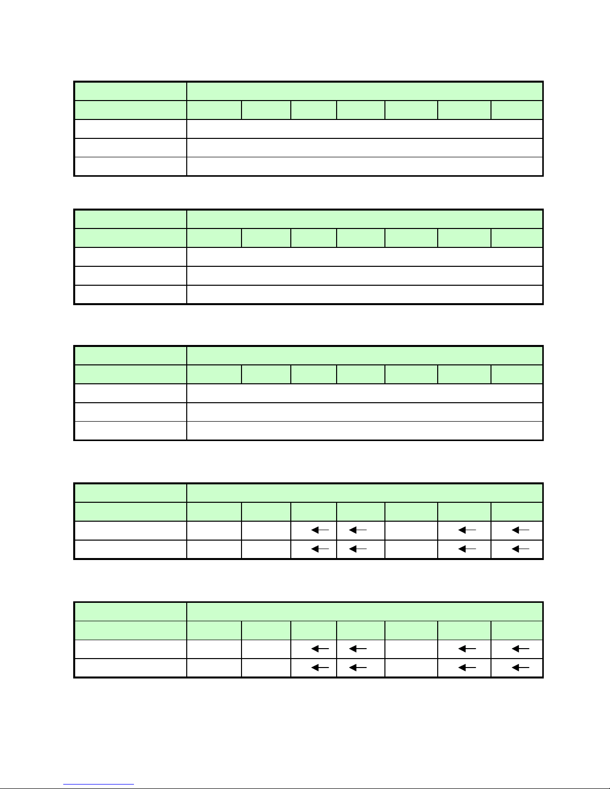
5) F-FAN MOTOR
REFRIGERANT R134a
VOLTAGE ( V/HZ) 100 /50,60 110 / 60 115,120/60 127/60 220/60 220~240 / 50 230 / 50
BL-2213DWFA-1
3015911300
REVOLUTION
DC 12V 2200RPM
6) R-FAN MOTOR
REFRIGERANT R134a
VOLTAGE ( V/HZ) 100 /50,60 110 / 60 115,120/60 127/60 220/60 220~240 / 50 230 / 50
BL-2213DWRA-1
3015911400
REVOLUTION
DC 12V 2200RPM
7) C- FAN MOTOR
REFRIGERANT R134a
VOLTAGE ( V/HZ) 100 /50,60 110 / 60 115,120/60 127/60 220/60 220~240 / 50 230 / 50
BL-2213DWCA-2
3015911500
REVOLUTION
DC 12V 2200RPM
8) DEFROST HEATER
REFRIGERANT R134a
VOLTAGE ( V/HZ) 100 /50,60 110 / 60 115,120/60 127/60 220/60 220~240 / 50 230 / 50
X 110V 140W 220V 140W
X 3012811210 3012811200
9) DRAIN HEATER
REFRIGERANT R134a
VOLTAGE ( V/HZ) 100 /50,60 110 / 60 115,120/60 127/60 220/60 220~240 / 50 230 / 50
X 110V 10W 220V 10W
X 3012811110 3012811100
PART CODE
TYPE NAME
PART CODE
SPEC (W)
SPEC (W)
PART CODE
TYPE NAME
TYPE NAME
PART CODE
PART CODE
- 11 -
Page 12
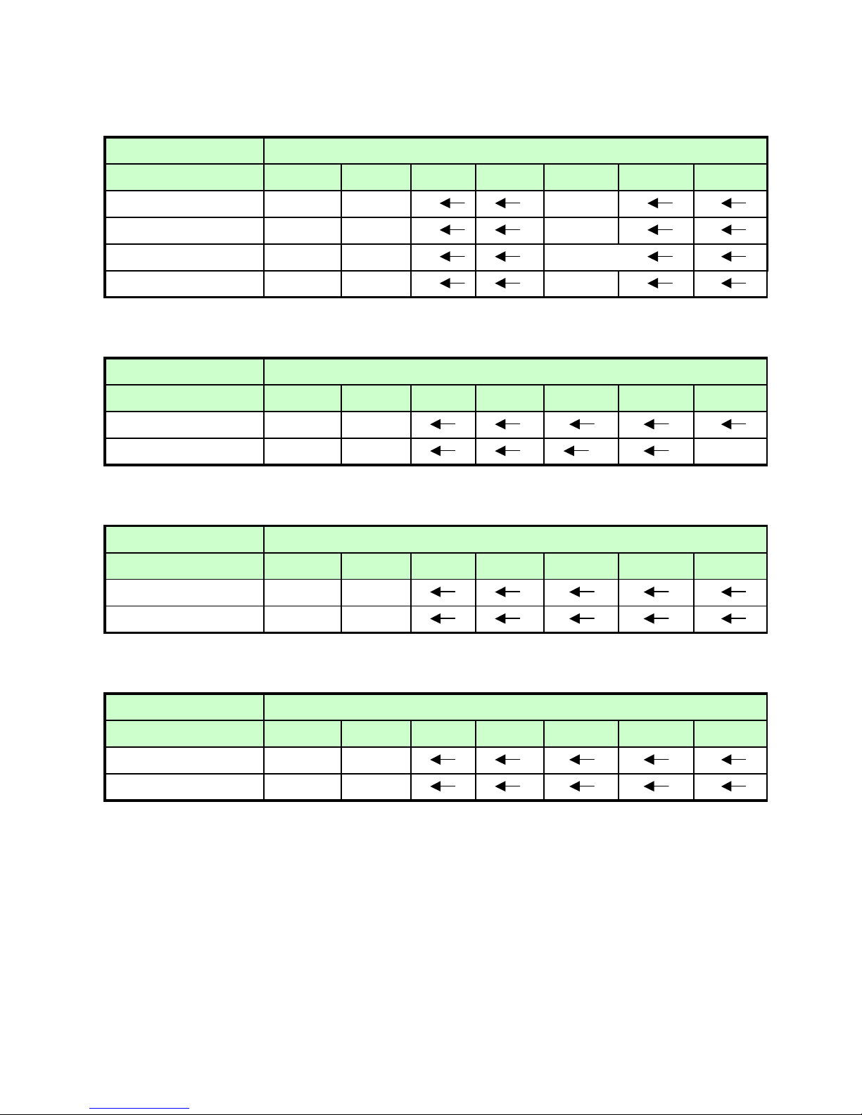
10) LAMP ASSEMBLY
REFRIGERANT R134a
VOLTAGE ( V/HZ) 100 /50,60 110 / 60 115,120/60 127/60 220/60 220~240 / 50 230 / 50
X 120V 15W 240V 15W
X 3013600070 3013600060
X 120V 25W 230~240V 25W
X 3013602020 3013602010
11) MAIN PCB ASSEMBLY
REFRIGERANT R134a
VOLTAGE ( V/HZ) 100 /50,60 110 / 60 115,120/60 127/60 220/60 220~240 / 50 230 / 50
X Y202-SBS
X 30143B4011 30143B4021
12) FUSE (PCB)
REFRIGERANT R134a
VOLTAGE ( V/HZ) 100 /50,60 110 / 60 115,120/60 127/60 220/60 220~240 / 50 230 / 50
RATED CURRENT
X 250V/3.15A
X 5F3GB3282R
13) THERMOSTAT FUSE
REFRIGERANT R134a
VOLTAGE ( V/HZ) 100 /50,60 110 / 60 115,120/60 127/60 220/60 220~240 / 50 230 / 50
x
77℃
x 30127201400
PART CODE
TYPE NAME
PART CODE
SPEC (W)
PART CODE
PART CODE
OPERATING TEMPERATURE
SPEC (W)
PART CODE
- 12 -
Page 13
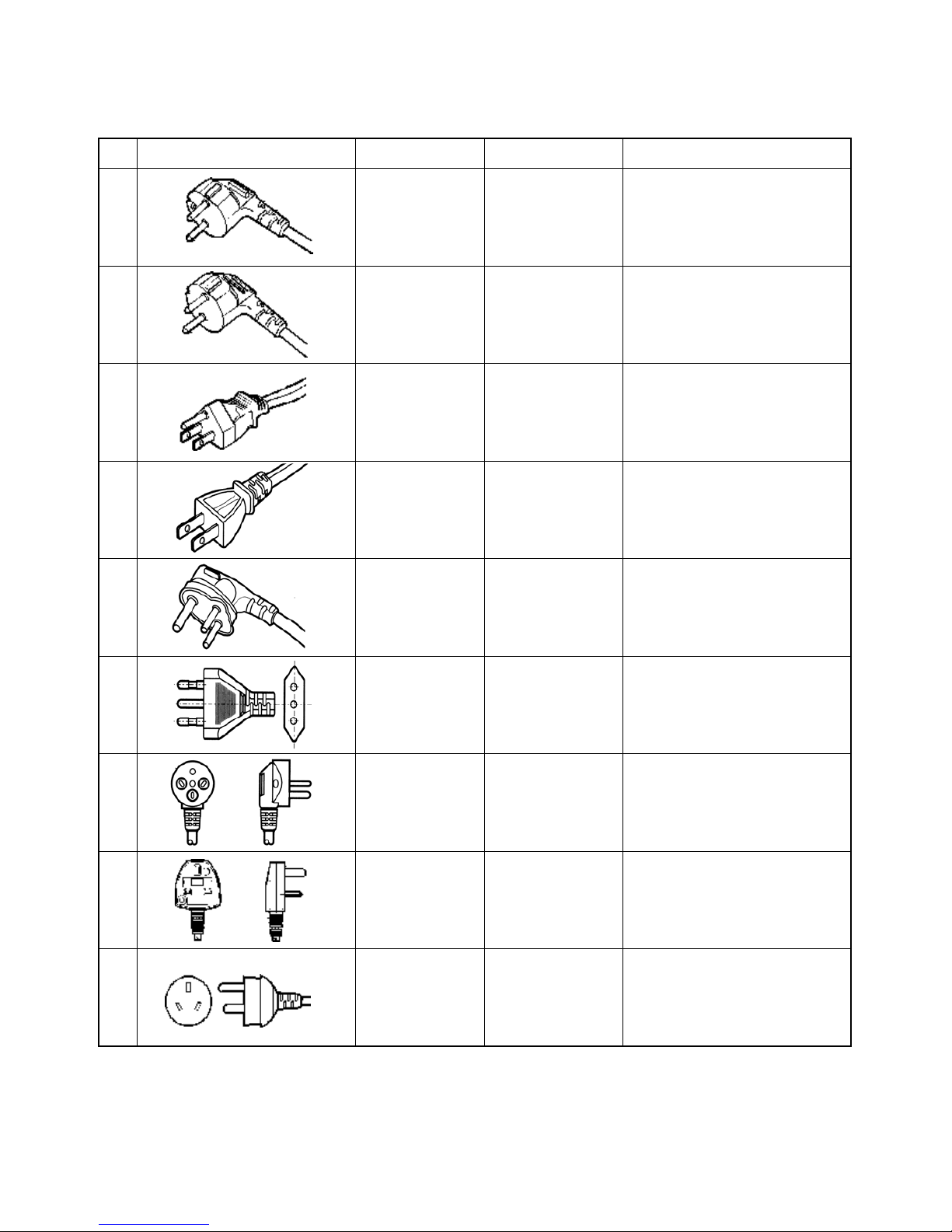
2-3. POWER CORD
NO SHAPE OF POWER CORD PART CODE DESCRIPTION REMARK
1 3011315000 CP-2PIN For european country
2 401RA17200 CP-2PIN For other country
3 4006D17101 KP-30 For America & El Salvador
4 401PD17101 KP-211 For Japan & Taiwan
5 3011300801 BP-3PIN
6 3011303010 # 267 For Chile
7 3011315310 For Israel
8 3011303050 BS-1363A
For U.K, Middle Asia
Singapore & Malaysia
9 3011301200 KP-551/550 For China & Australia
※ Upper power cord's part code is only lead wire, without any kinds of terminal or houisng
- 13 -
Page 14
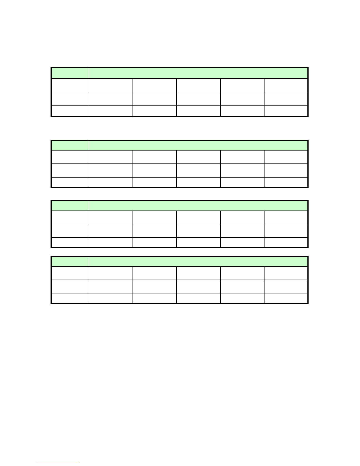
2-4. DOOR COLOR
1) ASSEMBLY URETHAN FREEZER DOOR
FRS-2021 / FRS-2401 / FRS-2421 / FRS-2441
Refrigerant Cyclo Pentane
COLORTYPE
Bright White PCM White Emboss Beige Emboss
Inox Looking Ellio1Inox Looking Ellio
2
COLOR COD
E
RWB3C GWG1B FBG3B DSG1E ISG3E
PARTCODE
3000018730 3000018720 3000018710 3000018740 3000018700
2) ASSEMBLY URETHAN REFRIGERATOR DOOR
a. FRS-2021 / FRS-2421
Refrigerant Cyclo Pentane
COLORTYPE
Bright White PCM White Emboss Beige Emboss
Inox Looking Ellio1Inox Looking Ellio
2
COLOR COD
E
RWB3C GWG1B FBG3B DSG1E ISG3E
PARTCODE
3000018830 3000018820 3000018810 3000018840 3000018800
b. FRS-2041 / FRS-2441 (220V ~ 240V)
Refrigerant Cyclo Pentane
COLORTYPE
Bright White PCM White Emboss Beige Emboss
Inox Looking Ellio1Inox Looking Ellio
2
COLOR COD
E
RWB3C GWG1B FBG3B DSG1E ISG3E
PARTCODE
3000025330 3000025320 3000025310 3000025340 3000025300
c. FRS-2041 / FRS-2441 (100V ~ 127V)
Refrigerant Cyclo Pentane
COLORTYPE
Bright White PCM White Emboss Beige Emboss
Inox Looking Ellio1Inox Looking Ellio
2
COLOR COD
E
RWB3C GWG1B FBG3B DSG1E ISG3E
PARTCODE
3000025380 3000025370 3000025360 3000025390 3000025350
- 14 -
Page 15
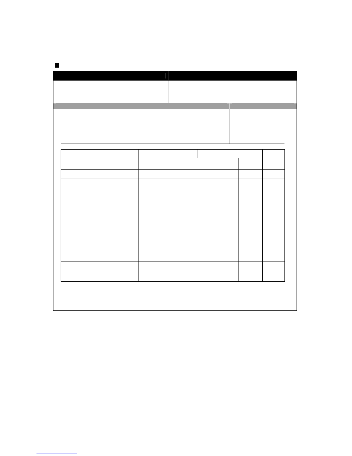
Display
INPUT Control Object
Front PCB buttons
FRZ SET. button / REF SET. button
SUPER FRZ. button / SUPER REF. button
LOCK button / SLEEP button
LCD
CONTENTS REMARKS
1. Normal Operation
1) Temperature control of Freezer / Refrigerator
( Initial mode : Freezer & Refrigerator -> Middle )
2) Lock mode : unlock(OFF) / Sleep mode : OFF
3) SPEED icon : inactive
4) FUZZY & DEODORIZER letters and icons : always ON
5) Other display modes
Normal Operation Silent Mode
CUSTOM LCD
Normal
Mode
Load Mode
Silence
Mode
Sleep
Mode
Freezer / Refrigerator BAR DIAL DIAL DIAL DIAL DIAL
Temp. SEG. DIAL DIAL DIAL DIAL DIAL
1) Letters of [FRZ., REF., LOW,
HIGH, SET TEMP, C, FUZZY,
DEODO., SILENT, SLEEP]
2) Icons of
[FUZZY, DEODO., SLEEP]
3) Temp. bars and lines
ON ON ON ON ON
SILENT icon OFF OFF ON ON OFF
SPEED letters OFF ON ON OFF OFF
SPEED bars OFF
ON
(progressive)
ON
(progressive)
OFF OFF
LOCK ON/OFF, SLEEP ON/OFF
DIAL DIAL DIAL DIAL DIAL
3. OPERATION AND FUCTIONS
- 15 -
Page 16

CONTENTS REMARK
2. "FRZ SET." button
1) Temperature control of Freezer compartment
2) 5 steps of sequential temperature mode
Initial mode by power input : “MID” (Temperature and bars are shown.)
* Letters are not indicated at Soft-Mid and Mid-Strong modes.
(Just temperatures and bars are shown.)
Temperature progress : Low -> (Low-Mid) -> Mid -> (Mid-High) -> HIgh
Temp. indication : -15C -17C -19C -21C -25C
Number of bars : 5EA 3EA 5EA 3EA 5EA
3. "SUPER FRZ." button
When this mode is chosen, “QUICK” icon and letters of freezer flicker 3 times and
ON. (The set temperature and bars are still the previous value.)
4. "REF SET.” button
1) Temperature control of Refrigerator compartment
2) 5 steps of sequential temperature mode
Initial mode by power input : “MID” (Temperature and bars are shown.)
* Letters are not indicated at Soft-Mid and Mid-Strong modes.
(Just temperatures and bars are shown.)
Temperature progress : Low -> (Low-Mid) -> Mid -> (Mid-High) -> HIgh
Temp. indication : 4C 3C 2C 1C 0C
Number of bars : 5EA 3EA 5EA 3EA 5EA
5. "SUPER REF." button
When this mode is chosen, “QUICK” icon and letters of refrigerator flicker 3 times
and ON. (The set temperature and bars are still the previous value.)
6. "SLEEP" button
1) Start by pushing the button ("ON" lights.)
2) Stop by pushing button again ("OFF" lights.)
3) Automaticcally terminated after maximum 12 hours ("OFF" lights.)
7. "LOCK" button
1) Start by pushing the button ("LOCK" letters and icon light.)
* No other buttons and modes, buzzer sound are controllable.
2) Stop by pushing button again for a second ("OFF” and icon light.)
- 16 -
Page 17
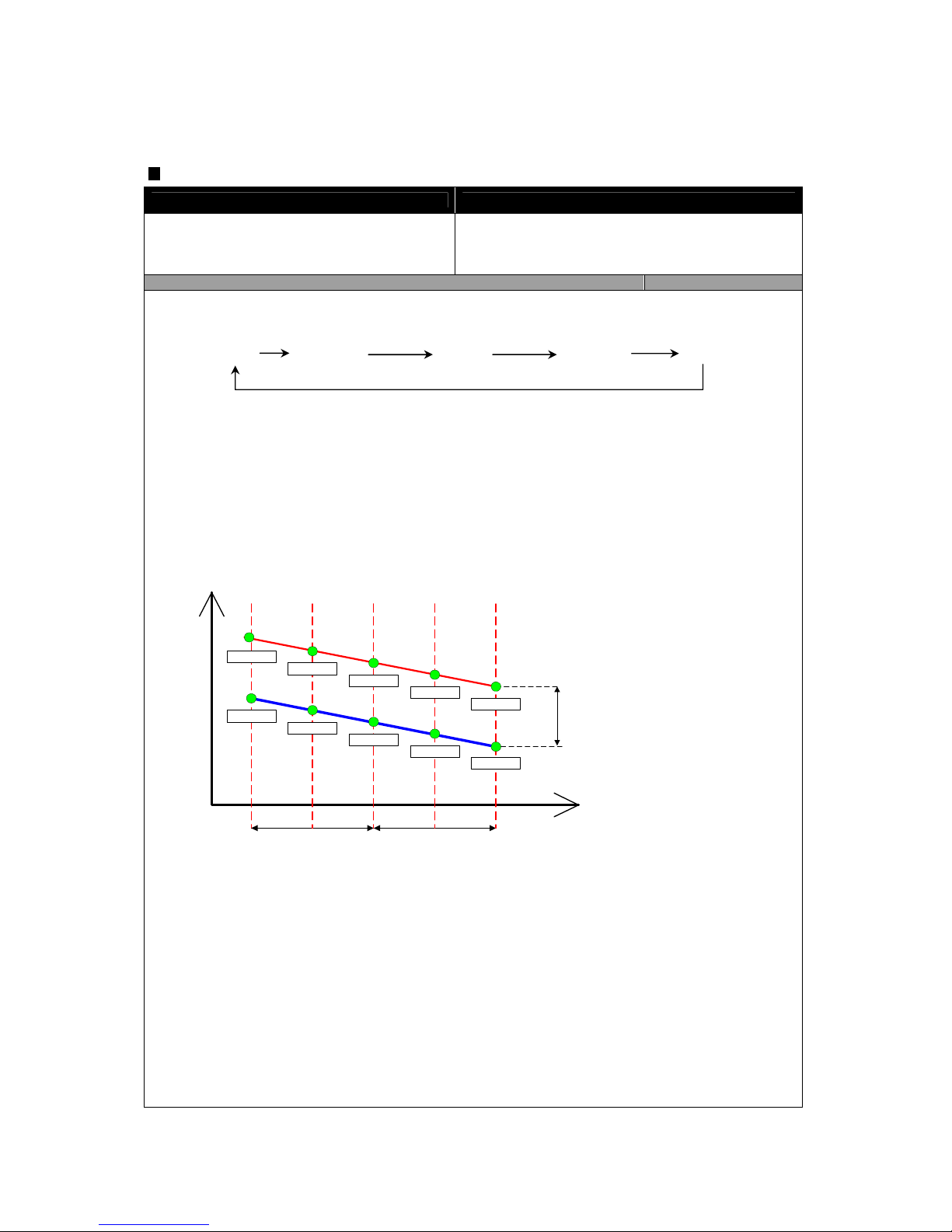
Temperature Control of Freezer Compartment (FC)
INPUT Control Object
1. FRZ SET. button / SUPER FRZ. button
2. F-sensor
1. COMP
2. F-FAN
CONTENTS REMARKS
1. Temperature modes change by pushing the button.
2. Comp. and F-fan are controlled by ON / OFF point of each mode.
3. FC [ON / OFF] DIFF : 5
C
( Freezer middle OFFpoint : -20.0 C
4. FC [Low -> (Low-Mid) -> Mid -> (Mid-High)] DIFF : 2 degrees respectively
( * [(Mid-HIgh) -> High] DIFF : 4 degrees )
5. Control point of each mode
Temp.
MODE
ON point
OFF point
Low
Mid
High
STEP DIFFSTEP DIFF
ON/OFF DIFF
-15.0C
-20.0C
-21.0C
-26.0C
-11.0C
-16.0C
-22.0C
-18.0C
-13.0C
-20.0C
(Low-Mid) (Mid-High)
Low Low-Mid
Mid
Mid-High High
- 17 -
Page 18
CONTENTS REMARKS
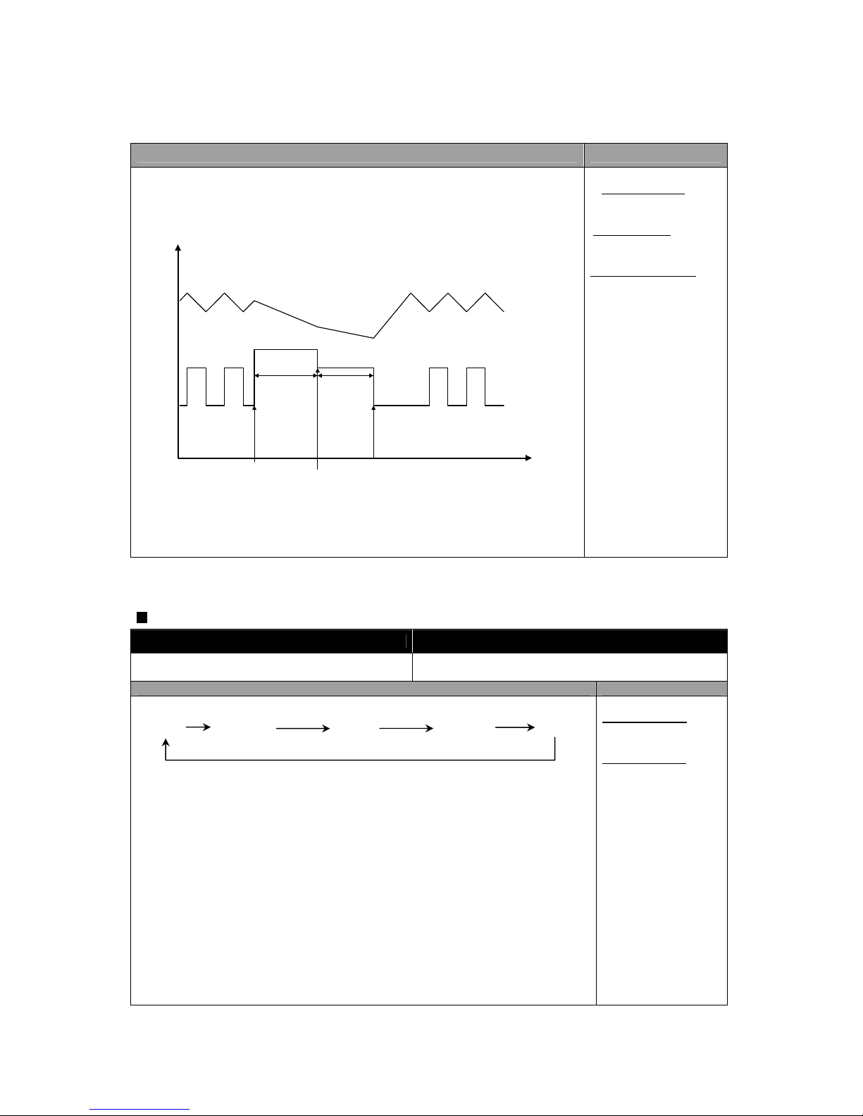
6. SUPER FRZ. (Quick Freezing)
1) Comp. and F-fan are ON (about 150 minutes) regardless of F-sensor.
2) F-fan runs at 14V for the first 90 min., then at 12V for the rest time.
F/S
F Fan
SUPER FRZ. start
F-fan RPM
change point
Normal operation
90min.
14V
12V
60min.
* ON/OFF DIFF. :
fixed by MICOM
* STEP DIFF. :
fixed by MICOM
* Comp. and C-fan :
linked
Temperature Control of Refrigerator Compartment (RC)
INPUT Control Object
1. REF SET. button
2. R-sensor
1. COMP
2. R-FAN
CONTENTS REMARKS
1. Temperature modes change by pushing the button.
2. R-fan are controlled by ON / OFF point of each mode.
3. RC [ON / OFF] DIFF : 0.35C
( RC middle OFF point : 0.3C)
4. RC [Low -> (Low-Mid) -> Mid -> (Mid-High)] DIFF : 1 degree respectively
5. Prevention of weak/poor-refrigeration
1) When weak refrigeration is sensed, comp. is ON regardless of F-sensor.
2) When R-sensor reaches R-fan OFF point, comp. is controlled by F-sensor and
R-fan turns OFF.
3) Sensing point of weak refrigeration : R
-sensor OFF point of each mode + 7C
4) Termination point : Same as R-sensor OFF point of each mode
* ON/OFF Diff. :
fixed by MICOM
* STEP DIFF. :
fixed by MICOM
Low Low-Mid
Mid
Mid-High High
- 18 -
Page 19
CONTENTS REMARKS
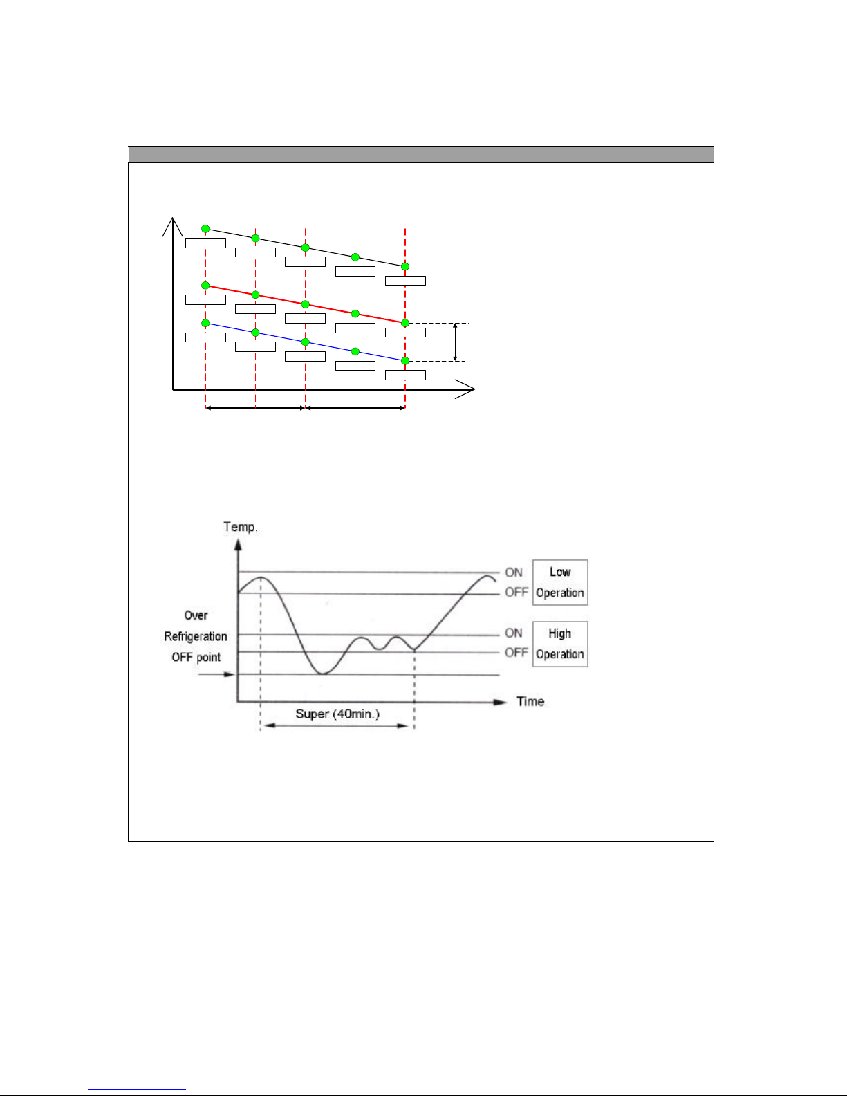
6. Control point of each mode
Temp
MODE
ON point
OFF point
Low
Mid
High
STEP DIFFSTEP DIFF
ON/OFF
DIFF
(0.35 deg)
0.65
2.65
2.3
-1.35
-1.7
Weak refrigeration point
(Off point+7C)
7.3
1.65
-0.35
-0.7
1.3
(Low-Mid) (Mid-High)
0.3
6.3
5.3
8.3
9.3
C
7. Super refrigeration proceeds for 40 minutes.
* Example of temperature change
(Refrigerator ; Low (normal) -> Super refrigeration )
1) R-fan and comp. are ON until R-sensor reaches to over-refrigeration OFF
point (-7C).
2) After reaching to the point, it goes on with “HIGH” mode until the end of
Super refrigeration.
It returns to normal after Quick refrigeration of 40 minutes.
- 19 -
C
C
C
C
C
C
C
C
C
C
C
C
C
C
Page 20

SLEEP Mode
INPUT Control Object
1. SLEEP button
1. COMP
2. R-FAN
3. F-FAN
4. CUSTOM-LCD
CONTENTS REMARKS
1. This mode starts with a push of “SLEEP” button.
2. Conditions to start Sleep mode
1) F-sensor < -13C
2) Unless it is a restart within 40 minutes after the end of previous Sleep mode
3) F-sensor error
4) Door switch error
5) Defrosting (Heater defrosting, pause, Fan delay)
6) If the above conditions of 1) ~ 5) are all satisfied, the sleep mode starts.
3. Control of electrical parts
1) Mode 1
Once Sleep mode starts, all the electrical parts (COMP, F-FAN, R-FAN) turn OFF.
(“ON” letters of SLEEP on LCD is display.)
2) Mode 2
It operates with Silent mode and “ON” letters of SLEEP on LCD is displayed on.)
4. Termination of Sleep mode
1) MODE 1
a. F-sensor > -9C
b. In case of F-sensor error
c. When other button is pushed during this mode
d. Total F/R door open time exceeds 30 seconds during the mode
e. If Sleep mode is terminated by a, b and f, F/R-fan delay for 5 minutes and
restart of this mode is prevented for 40minutes.
f. It it exceeds time limit of 130 minute, Mode1 is terminated and Mode2 starts.
2) MODE 2
Sleep mode is terminated 12 hours after the first start.
( Speed mode and defrosting operate in normal way.)
5. After Sleep mode stops all the electrical parts return to normal operation and Sleep
icon changes from “ON” to “OFF”.
6. If Sleep mode starts during PRECOOL, it goes on again after the Sleep mode is
terminated.
7. If Sleep mode starts during Super FRZ., Super REF., it returns to previous set
modeafter the Sleep mode is terminated.
- 20 -
=
=
Page 21
SILENT (Silence Mode)
INPUT Control Object
1. CDS SENSOR
5. COMP
6. R-FAN
7. F-FAN
8. CUSTOM-LCD
CONTENTS REMARKS
1. Purpose of Silence mode
To reduce refrigerator noise at night by decresing fan RPM to a minimum degree
2. Condition to start
1) The optical or light sensor in top middle of control panel senses surround light and
Silence mode starts if the amount of light sensed is below the standard value for
more than 1 minute.
(The mode does not start for initial 240 minutes to prevent down of cooling
performance.)
a. Standard value to decide ‘night’ : below 5~7 Lux (optical sensor surface)
b. Standard value to decide ‘daytime’ : above 4~16 Lux
(optical sensor surface)
3. Control Method
Control Mode F-FAN R-FAN C-FAN
Normal
10V 10V 10V
Silence
Load
Control
12V 12V 10V
4. Termination Condition
The mode stops if lux value is above the standard for more than 1 minute.
Control of Each Mode
INPUT Control Object
1. CDS SENSOR
2. R SENSOR
3. F SENSOR
1. F-FAN (14V, 12V, 10V)
CONTENTS REMARKS
* Control of Silence mode : operation mode when the optical sensor feels that it is
night
* Normal control : daytime operation mode
(Refrigerator noise is relatively low at daytime.)
* Load control : operation mode when inside temperature goes up due to an
increase of load (foods) or frequent door openings
- 21 -
Page 22
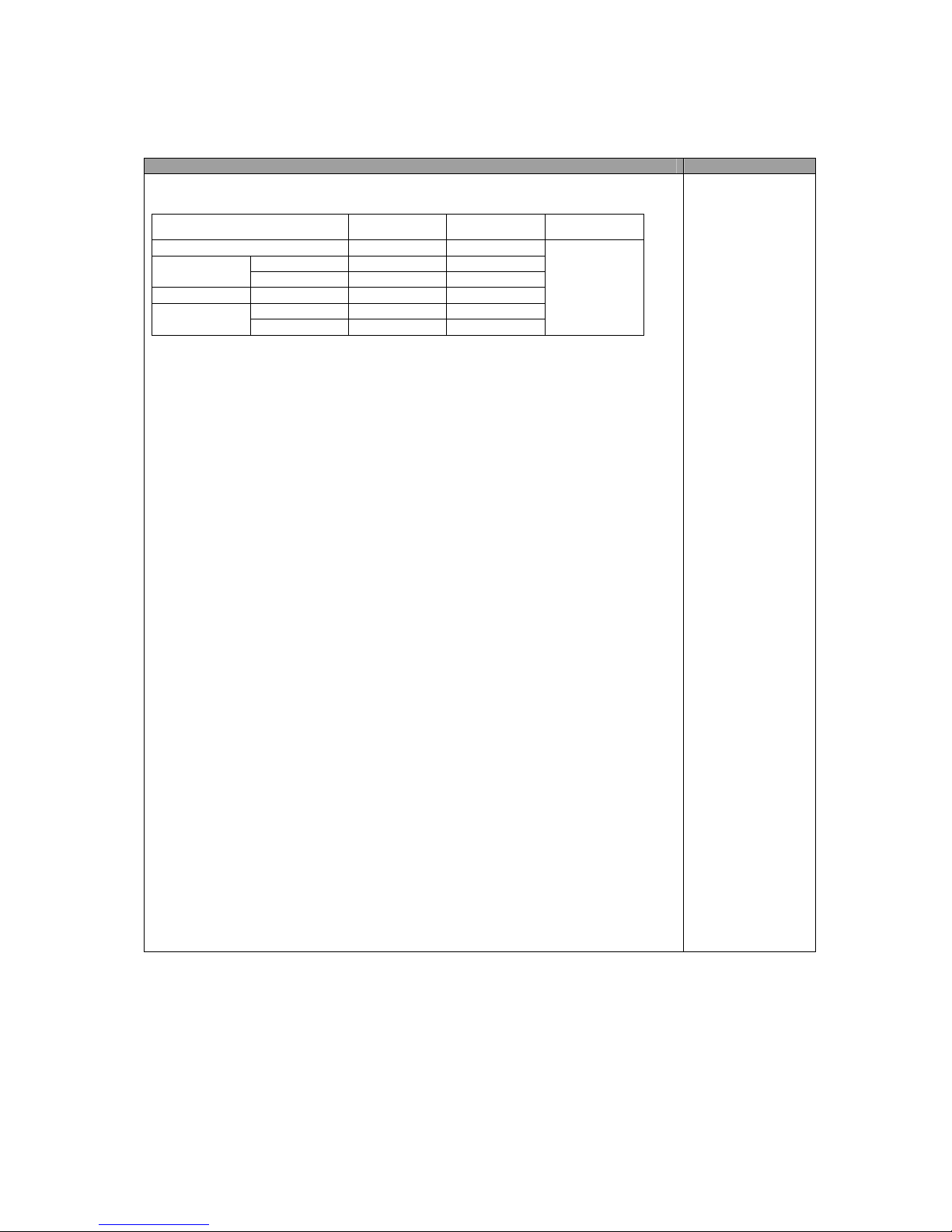
CONTENTS REMARKS
1. Fan voltage of each control mode
2. Control against (under) load (Load Control)
1) Purpose : To restore F/R-temperature which has risen by load (much foods in or
frequent door openings) as soon as possible
2) Display : "SPEED" lights until the mode and speed icons flicker.
3) Conditions to start (from both Normal and Silence)
a. F or R door open time exceeds 30 seconds at a time -> Freezer and Refregerator
load control starts respectively.
Over [F-sensor On Point + 5b. degree] -> F
load control
c. Over [R-sensor On Point + 5 degree] -> R load control
4) Conditions to avoid load control
a. Initial operation (rught after power input) of refrigerator
b. Just after Pre-cool, Heater defrosting, Pause, Defrosting cycle
5) Control Method
5-1) Control mode by F/R-door open time (over 30 seconds)
-> F/R-fan works by 14V respectively.
5-2) Control mode by [F-sensor On Point + 5 degree]
-> F-fan works by 14V.
5-3) Control mode by [R-sensor On Point + 5 degree]
-> R-fan works by 14V.
* C-fan works by 10V as normal.
6) Conditions to stop
a. The mode works for 20 minutes.
(If another condition happens at the end of the mode, it starts again.)
b. When it reaches to [F-sensor Off point], F-fan load control mode stops.
c. When it reaches to [R-sensor Off point], R-fan load control mode stops.
Control Mode F-FAN R-FAN C-FAN
Normal 12V 12V
Normal 14V 14V
Load Control
Silence 12V 12V
Silence Normal 10V 10V
Normal 10V 10V
Sleep Mode2
Load control
12V 12V
10V
- 22 -
Page 23
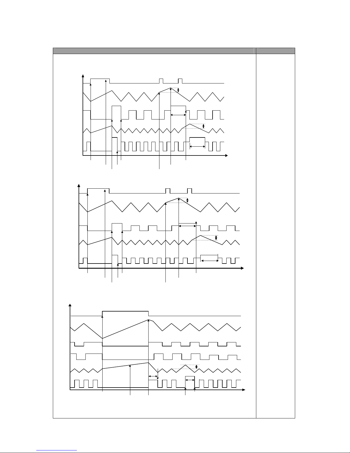
CONTENTS REMARKS
3. Control Time Chart of Each Mode
1) Start & stop of load control mode (Normal Control)
Door
F/S
F Fan
R/S
R Fan
Door Open
30 sec. after Open
Load Mode Start
Frz. Load Stop
Rez. Load Stop
On + 5deg
On + 5deg
Frz. Overload Input
Frz. Start Condition
Frz. Stop ; after 20min.
20min.
20min.
Ref. Load
14V
14V
12V
12V
2) Start & stop of load control mode (Silence Control)
Door
F/S
F Fan
R/S
R Fan
Door Open
30sec. after open
Load Mode Start
Ref. Load Stop
Frz. Load Stop
On + 5deg
On + 5deg
Frz. Overload Input
Frz. Load Start
Frz. Stop Condition ;
after 20min.
20min.
20min.
Ref. Load
12V
12V
10V
8V
3) Start & stop of load control mode (Normal defrosting control)
F/S
F Fan
R/S
R Fan
Defrosting Start
Condition to start Load
Mode, but avoided
buring defrosting mode
Ref. Load Stop
On + 5deg
Normal Operation
20min.
Ref. Load Mode
14V
12V
8V
HTR
Comp
- 23 -
Page 24
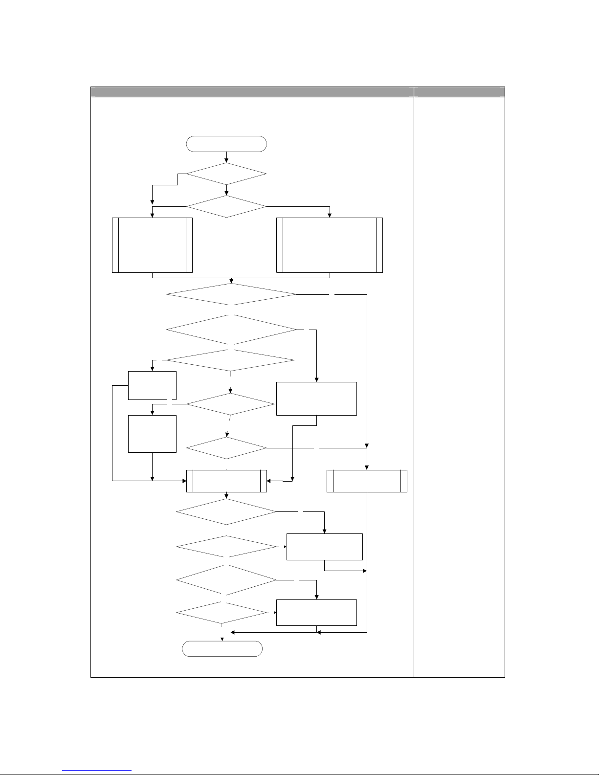
CONTENTS REMARKS
4. Flow Chart of Load Control Mode
Sart
F/R door open time is over 30 sec. ?
F/S ON + 5deg?
R-sensor ON + 5deg?
Fan RPM
F Fan : 12V
R Fan : 12V
C Fan : 10V
Fan RPM
Normal Overload
F Fan : 10V 12V
R Fan : 10V 12V
C Fan : 10V 12V
Overload of both
compartments
Y
N
Freezer
Compartment
Overload
Refrigerator
Compartment
Overload
Y
N
Y
N
F load control ;
over 20 min. ?
F-sensor OFF point ?
Overload mode control
Overload mode ?
Normal mode
control
N
F load control mode stop
R-sensor OFF point ?
R load control mode
stop
End
Load control is avoided ?
N
Y
R load control ;
over 20 min. ?
Y
Y
Y
N
Y
N
N
Y
N
Control Mode
Normal
240 minutes ?N
Silence
- 24 -
Page 25
Defrosting Cycle
INPUT Control Object
1. Total comp. work time
2. Comp. work rate
3. RT temperature
4. Total door open time
1. Defrosting Mode
CONTENTS
REMARKS
1. Conditions to start defrosting cycle
1) Total comp. work time : 6, 8, 10 hours
2) Comp. work rate (by the 2 hours) : over 65%
3) Total door open time : 3 minutes
(Any door - F or R – open time is over 3 minutes.)
4) Total time of [comp. ON + comp. OFF] : 60 hours
5) Ambient temperature : over 35C
6) Any error mode : R1, F1, D1, F3, RT/S, Door-switch
2. Conditions to start defrosting mode
1) The mode starts in the following conditions ;
a. Any error happens when total comp. work time is 6 or 8 or 10 hours.
b. Comp. work rate by the 2 hours is over 65%.
c. Total door open time is over 3 minutes.
(Any door - F or R – open time is over 3 minutes.)
d. Ambient temperature is over 35C
2) Defrosting mode starts unconditionally as long as total comp. work time is 10 hours,
even if the above conditions (a~d ) are not satisfied.
3) Defrosting mode starts immediately as long as total time of [comp. ON + comp. OFF] is
over 60 hours, even if the above 1) and 2) conditions are not satisfied.
- 25 -
Page 26
CONTENTS REMARKS
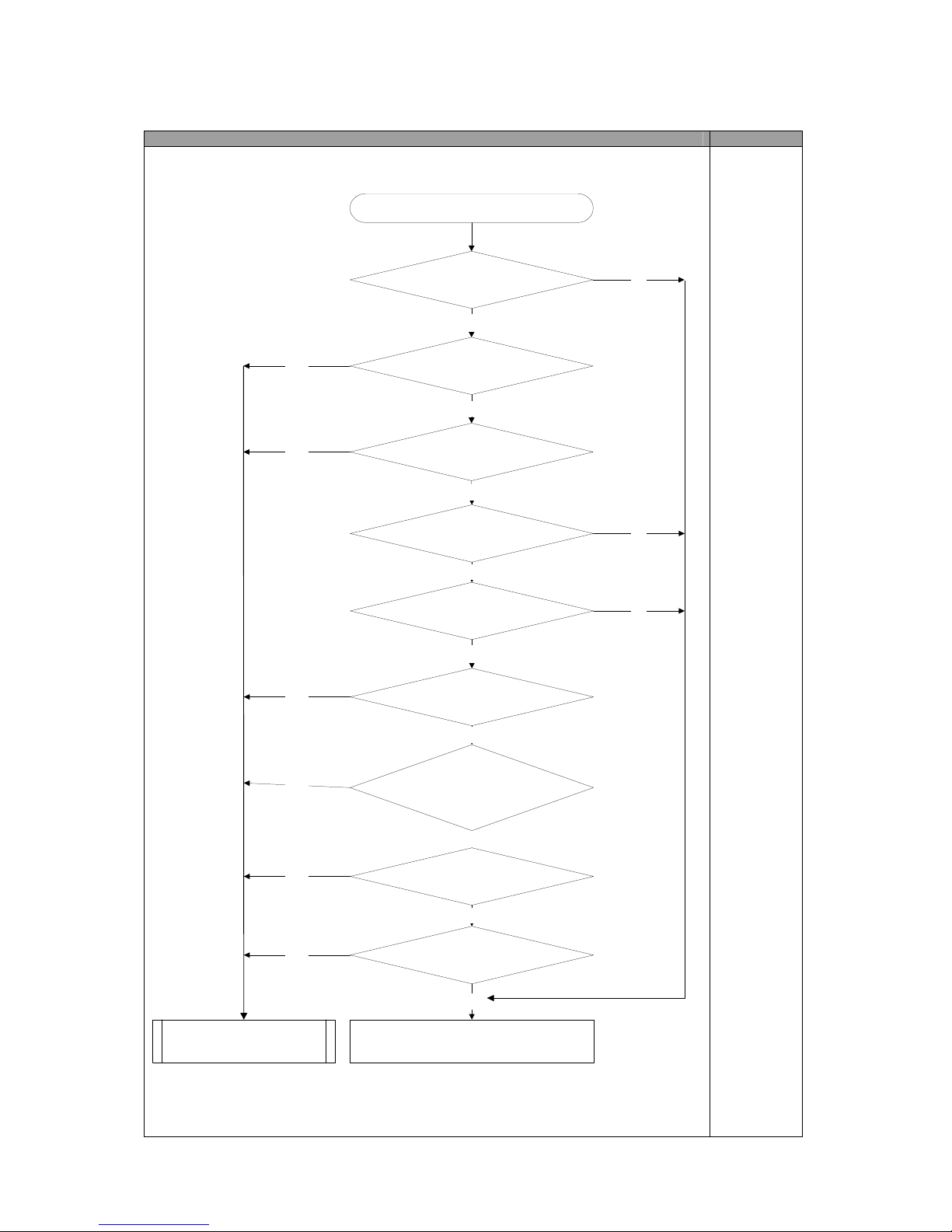
3. Flow Chart of Defrosting Start
Start
Ambient temp. is over 35C ?
Comp. work time is over 10 hours ?
Total time is over 60 hours ?
Comp. work time is over 6 hours ?
Any error ?
Comp. work rate is over 65 % ?
EndDefrosting mode starts.
Yes
Yes
Yes
Yes
Yes
Yes
No
No
No
No
No
No
Comp. work time is over 2 hours ?
Total door open time is over 3
minutes ?
Yes
Yes
No
No
Comp. work time is over 8 hours ?
No
No
- 26 -
Page 27
Defrosting Mode
INPUT Control Object
1. Defrosting Cycle
1. COMP
2. F-FAN
3. R-FAN
4. HEATER
CONTENTS REMARKS
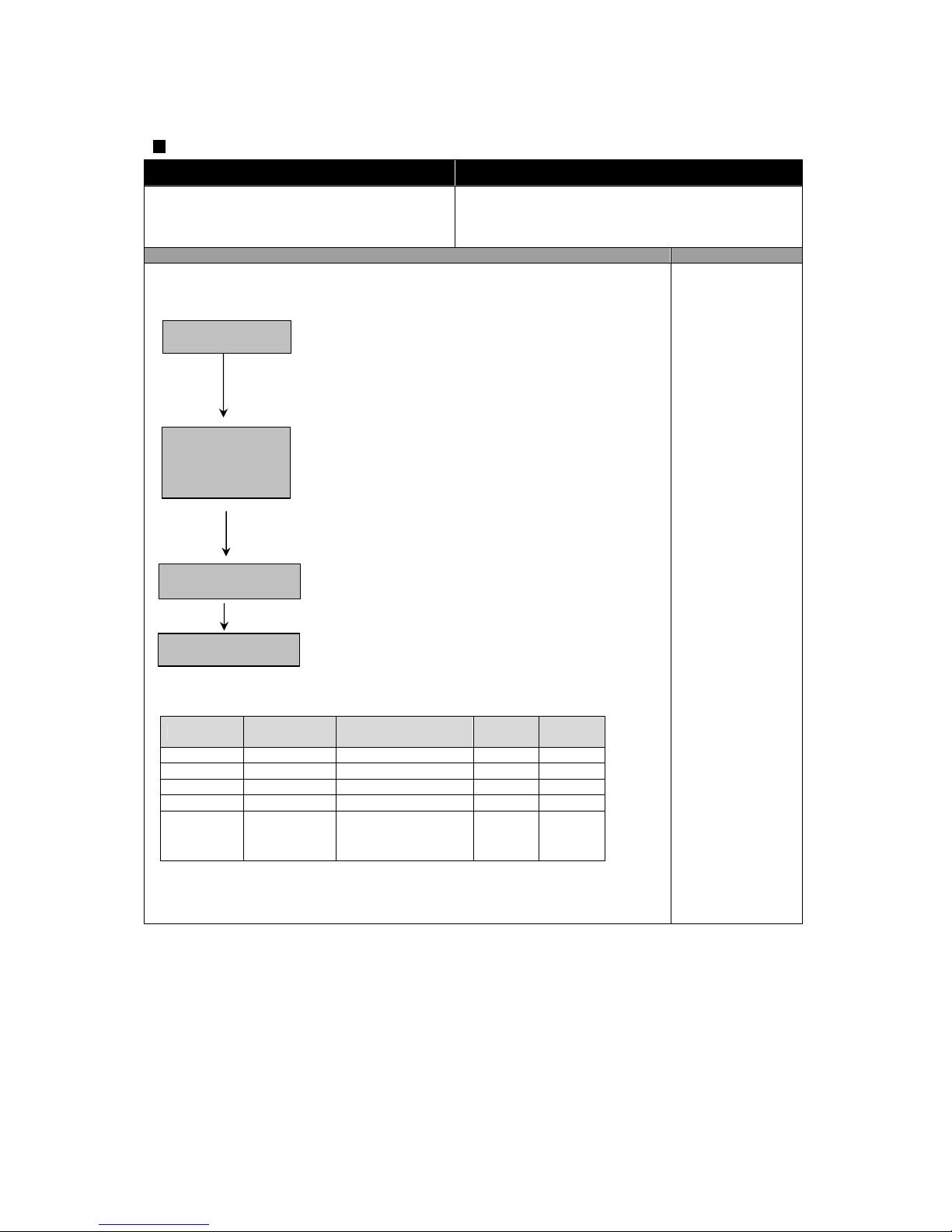
1. Defrosting Mode
1) Time ; 50 minutes
2) Comp. / F-fan : ON
R-fan : Control
Heater : OFF
3) If F-sensor < - 27C, PRE-COOL becomes OFF.
1) If D-sensor > 10C, Heater becomes OFF.
2) In case of Heater return by time limit of 40 or 80 min
(F3-Error)
3) Heater is ON for 30 minutes (time limit) in case of Dsensor error.
4) Time limit
a. 30 seconds : Heater is ON regardless of D-sensor
temperature right after defrosting start.
b. 30 minutes : in case of D1-Error
c. 80 minutes : in normal control state
1) Time : 7 minutes
Comp., F-fan, R-fan, Heater : OFF
1) Time : 5 minutes
Comp. : ON
F/R-fan, Heater : OFF
* Output control and time limit of each defrosting mode
PRE-COOL Heater Defrosting Pause
Fan
Delay
COMP ON OFF OFF ON
F-FAN ON OFF OFF OFF
R-FAN Control OFF OFF OFF
HEATER OFF ON OFF OFF
Time Limit
50 min.
a. 80 min.
b. 30 min.
(in case of D1-Error)
7 min. 5 min.
C-fan and comp.
are linked.
2. Initial Defrosting
If D-sensor < 3.5C, defrosting mode starts from Pre-Cool at initial power input or
first plugin.
Pre-Cool
Heater
Defrosting
Pause
Fan Delay
- 27 -
=
=
=
Page 28
Error Display (LCD Display of F-PCB)
INPUT Control Object
1. Temperature Control Buttons CUSTOM LCD
CONTENTS REMARKS
1. How to start
1) Set “LOCK ON” first.
2) Push “LOCK” button 3 times while pushing “REF SET.” button at the same time .
2. Display
Error code is displayed on Freezer temperature display part.
3. How to stop
1) Push “LOCK” button 3 times while pushing “REF SET.” button.
2) It stops automatically 4 minutes after the start.
4. All the error Ccdes are reset if they turn to be normal.
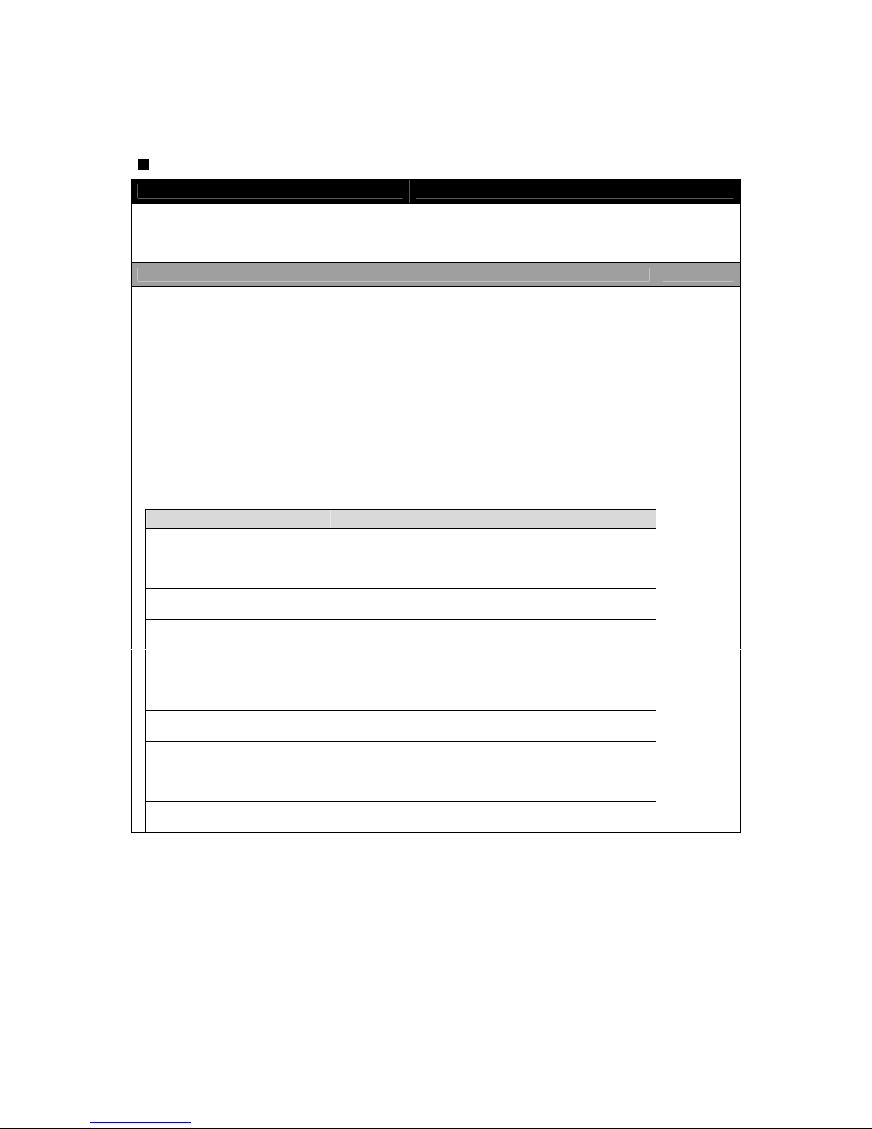
5. Error Code
ERROR CODE CONTENTS
F1 F-sensor ; disconnection, short(pull-down)
r1 R-sensor ; disconnection, short(pull-down)
rt RT-sensor ; disconnection, short(pull-down)
d1 D-sensor ; disconnection, short(pull-down)
dr R-Door Switch ; defective
dF F-Door Switch ; defective
dH Homebar (Refreshment Center) Door Switch ; defective
C1 Cycle ; abnormal or defective.
F3 Return after defrosting ; abnormal or defective
d2 Forced defrosting mode for A/S
- 28 -
Page 29
CONTENTS REMARKS
6. Control Way of Errors (if any)
1) "F1" ERROR
a. Cause : F-sensor disconnection / short (pull-down)
b. Control : Comp. / F-fan -> ON for 25min., OFF for 25min.
c. if F-sensor is normal, the error is terminated automatically.
2) "r1" ERROR
a. Cause : R-sensor disconnection / short (pull-down)
b. Control : Condition of ambient temperature
RT/S In ERROR
Work rate
ON/OFF
8 / 12 7 / 13 8 / 12 8 / 12 9 / 11
c. If R-sensor is normal, the error is terminated automatically.
3) "rt" ERROR
a. Cause : RT-sensor disconnection / short (pull-down)
b. Control : Normal operation, deletion of control condition by RT-sensor
c. If RT-sensor is normal, the error is terminated automatically.
4) "d1" ERROR
a. Cause : D-sensor disconnection / short (pull-down)
b. Control : Time limit (30min.) of defrosting-return
c. If D-sensor is normal, the error is terminated automatically.
5) Door ERROR("dF","dR","dH" on display)
a. Cause : in case it senses that door is open for more than 1
b. Control : Deletion of function related door switch sensing
c. If door switch (open & close) is sensed, the error is terminated automatically.
d. After displaying on LCD the mode is terminated.
6) "C1" ERROR
a. Cause : in case comp. works for over 3 hours when D-sensor temp. is over -5C
b. Control : Normal operation
c. When D-sensor temp. is below -5C in comp. OFF, it is terminated.
7) "F3" ERROR
a. Cause : in case defrosting-return is done by time limit of 80min.
b. Control : Deletion of Pre-cool mode in defrosting mode
c. If defrosting-return is done by D-sensor, it is terminated.
8) "d2" MODE (A/S forced defrosting mode)
a. Set “LOCK ON” first, then push “REF SET.” button 5 times while pushing “FRZ SET.”
button simultaneously.
b. Control : A/S forced defrosting control (Pre-cool is deleted.)
c. If D-sensor temp. is over 10C, the mode is terminated automatically.
- 29 -
~ 13C
14 ~ 19C
20 ~ 29C
29C ~
Page 30
Forced Defrosting
INPUT Control Object
1. “FRZ SET.” button
2. “REF SET.” button
3. “LOCK” button
Defrosting Mode
CONTENTS REMARKS
1. How to start
-> Set “LOCK ON” first, then push “REF SET.” button 5 times while
pushing “FRZ SET.” button simultaneously.
2. How to proceed
1) Delete Pre-cool mode. (Others are same as normal defrosting.)
2) Heater is ON regardless of D-sensor temp. at first 30 seconds.
( Check of defrosting current)
6-11. Initial Defrosting
INPUT Control Object
D-sensor
Initial or first power input (power plugin)
Defrosting Mode
CONTENTS REMARKS
If D-sensor temp. < 3.5C, defrosting mode starts from Pre-cool at first
power input.
Comp. is delayed for 6 min.
at the initial defrosting.
6-12. Buzzer or Alarm
INPUT Control Object
F-PCB buttons
Door Switch
Initial Power Input
BUZZER
CONTENTS REMARKS
1. Buzzer sounds if any button of F-PCB is pushed.
2. Buzzer sounds 3 times 3 minutes after initial power input.
3. Buzzer sounds for 1 second in case of A/S forced defrosting, short (pulldown) operation, explanation mode.
4. If door is open, buzzer sounds continually 3 times for 5 seconds.
(Door open alarm)
LCD Background Light
INPUT Control Object
F-PCB buttons
Door Switch
Initial Power Input
LCD BACK LIGHT
- 30 -
=
Page 31
CONTENTS REMARKS
1. Conditions to turn on LCD Light
1) Power input (plugin)
2) When any button on the panel is pushed, first the back light turns on, then
button control is done.
3) When F/R door is open, the light turns on.
2. Conditions to turn off the light
1) The back light turns off 10 seconds after F/R door is closed
2) 1 minute after button control
Explanation After Delivery
INPUT Control Object
“FRZ SET.” button
“REF SET.” button
Power Cord
Electrical components and LCD
CONTENTS REMARKS
1. Start
Push “REF SET.” button for 3 seconds within 10 seconds just after power
input.
2. Control
1) Electrical components are OFF for 3 hours.
2) Display operates in normal way.
Prevention of Compressor Restart
INPUT Control Object
None Comp.
CONTENTS REMARKS
Comp. does not start again for 6 minutes though F-sensor is ON. 6min. delay
- 31 -
Page 32
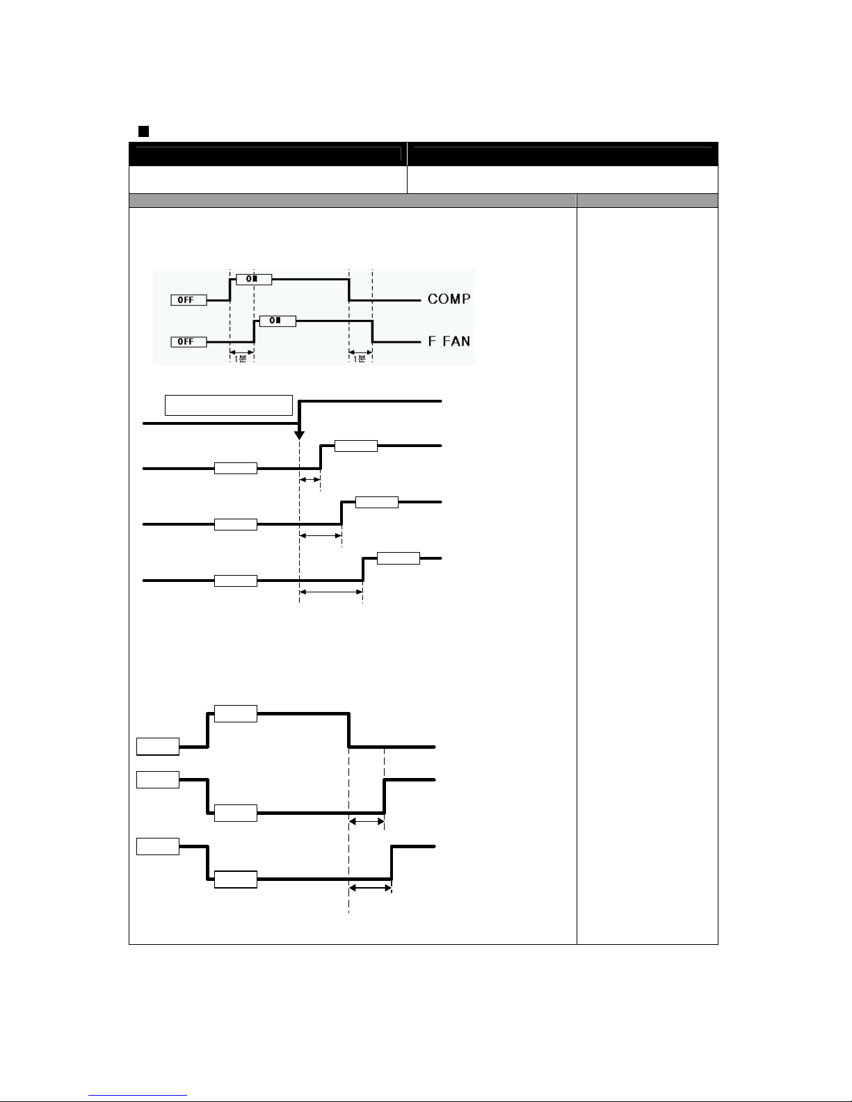
Delay Function of Electric Components
INPUT Control Object
COMP ON/OFF
COMP
F-FAN
CONTENTS REMARKS
1) F-fan delay by comp. ON/OFF
-> F-fan is ON/OFF 1 minute after comp. is ON/OFF.
2) Fan Delay and Priority
R FAN
ON condition
0.5sec.
ON
ON
ON
1.0sec.
1.5sec.
F FAN
C FAN
OFF
OFF
OFF
3) F/R-fan delay by door open/close for easy door
-> Inspection : checkup door opening 2 hours after initial start
-> First R is ON, 1 second later F is ON to protect DC fan against over current at
initial start.
DOOR
R FAN
OPEN
CLOSE
20.5 sec. (0.5sec.
for first 2 hrs.)
21sec. (1sec. for first 2 hrs.)
ON
OFF
ON
OFF
F FAN
- 32 -
1Min
1Min
Page 33
Home Bar (Refreshment Center) Heater (FR-S580CR MODEL)
INPUT Control Object
None COMP
CONTENTS REMARKS
It is linked with comp.
Control of Interior Lights
INPUT Control Object
Refrigerator Door
Freezer Door
Home-Bar Door
(Refreshment Center ; FR-S580CR)
COMP
CONTENTS REMARKS
1) Control of Refrigerator Compartment Lights
R lights turn ON/OFF by R-door switch (ON/OFF).
* 10 minutes after sensing door open, the lights turn off automatically though
door close is not sensed.
2) Control of Freezer Compartment Lights
F lights turn ON/OFF by F-door switch (ON/OFF).
* 10 minutes after sensing door open, the lights turn off automatically though
door close is not sensed.
3) R-lights ON/OFF by Home-Bar door opening
R-lights turn ON for 1 minute after sensing HOME-BAR switch open.
(If the switch is pushed again within 1 minute, the light turns on another 1
minute.)
Demonstration Function
INPUT Control Object
“LOCK” button
“REF SET.” button
“SLEEP” button
COMP
F-FAN
R-FAN
CONTENTS REMARKS
1. Start
1) Set “LOCK ON” first.
2) Push “SLEEP” button 5 times while pushing “REF SET.” button simultaneously.
2. Control
1) All other electrical components are OFF except for F-fan / R-fan.
2) Fan Control
DOOR OPEN -> FAN ON / DOOR CLOSE -> FAN OFF
3) Display : Normal mode (3.8sec.) -> SPEED(3sec.) -> Silent mode(3sec.) ->
Sleep mode (3sec.)
3. Stop or Termination
1) During Demo mode push “SLEEP” button 5 times while pushing “REF SET.”
button simultaneously.
2) Power in again.
- 33 -
Page 34
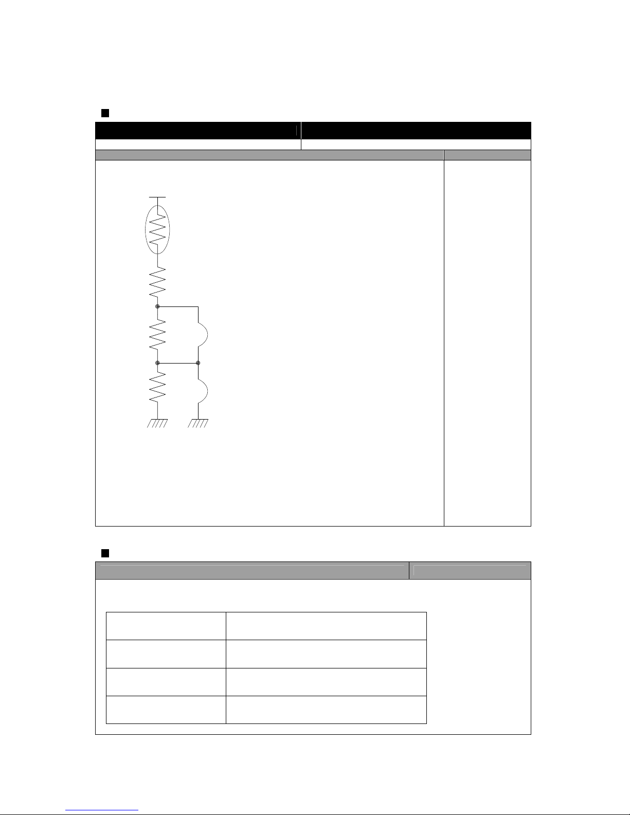
Regulation of R-sensor OFF Point
INPUT Control Object
J18, 22 on Main PCB Resistance of R-sensor Mid OFF Point
CONTENTS REMARKS
a. Regulation of R-sensor OFF point (1.5degree DOWN)
b. In case refrigeration of refrigerator is weak or insufficient, take the following action.
R-SENSOR
OP1-2
R26
R70
R71
OP1-1
a. R26 : R-SENSOR standard resistance in normal mode (31.4K )
b. R70 : In case of weak ref., cut J18 to down the standard resistance by 1.5deg(2K)
c. R71 : In case of weak ref., cut J22 to down the standard resistance by 1.5deg(2K)
R26 = Mid OFF point
R26 + R70 = Mid OFF point - 1.5 deg
R26 + R70 + R71 = Mid OFF point - 3.0 deg
Summary of Function
CONTENTS REMARKS
* How to start function modes
* All the modes are started with “LOCK ON” except for “explanation after delivery & installation”.
A/S forced defrosting “FRZ SET.” + “REF SET.” 5 times
Demonstration “REF SET.” + “SLEEP” 5 times
Explanation after delivery &
installation
“REF SET.” for 3 sec. Right after first power in
ERROR display “REF SET.” + “LOCK” 3 times
- 34 -
Page 35
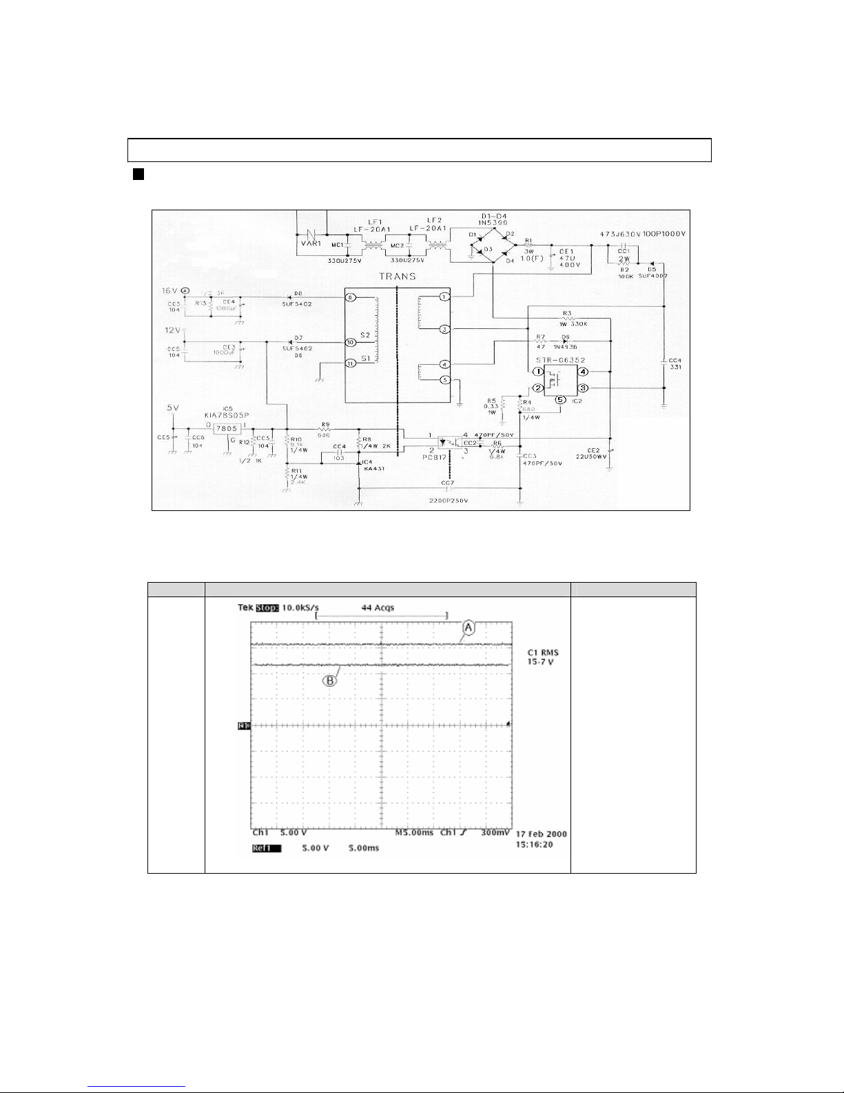
MICOM Circuit
Power
Circuit
DC Output Power (Voltage)
Point Oscilloscope Measurement Remarks
* DC output
15.7V
11.96V
- 35 -
Page 36
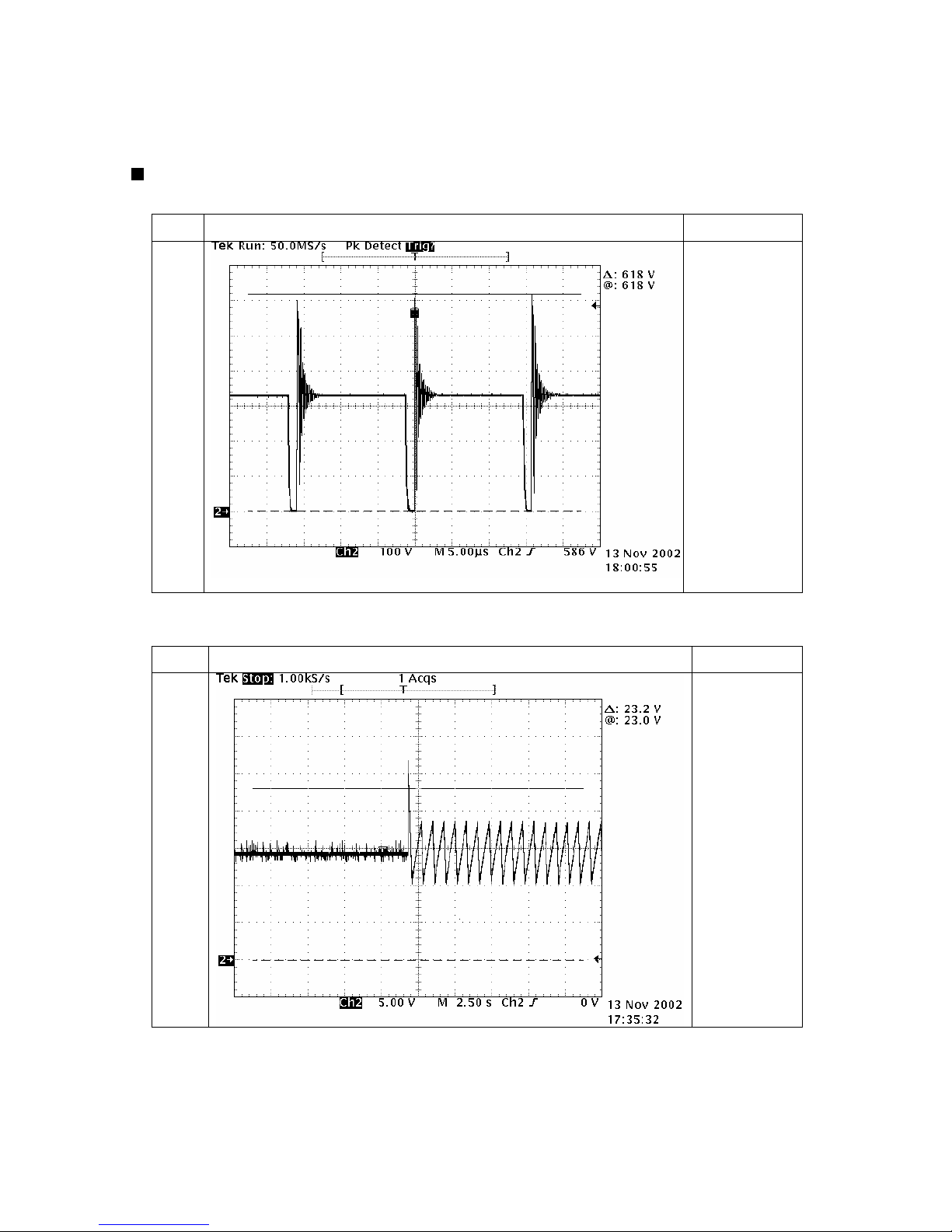
SMPS Movement Wave
Drain to Source Break Voltage
Point Oscilloscope Measurement Remarks
SMP
SIC
PIN
1,2
*Voltage between
DRAIN and
SOURCE :
below 650V
OVP(Overvoltage Protection) Wave at power input
Point
Oscilloscope Measurement
Remark
SMPS
IC PIN
3,4
*Minimum
standard
voltage at OVP
start :
23.2V
- 36 -
Page 37
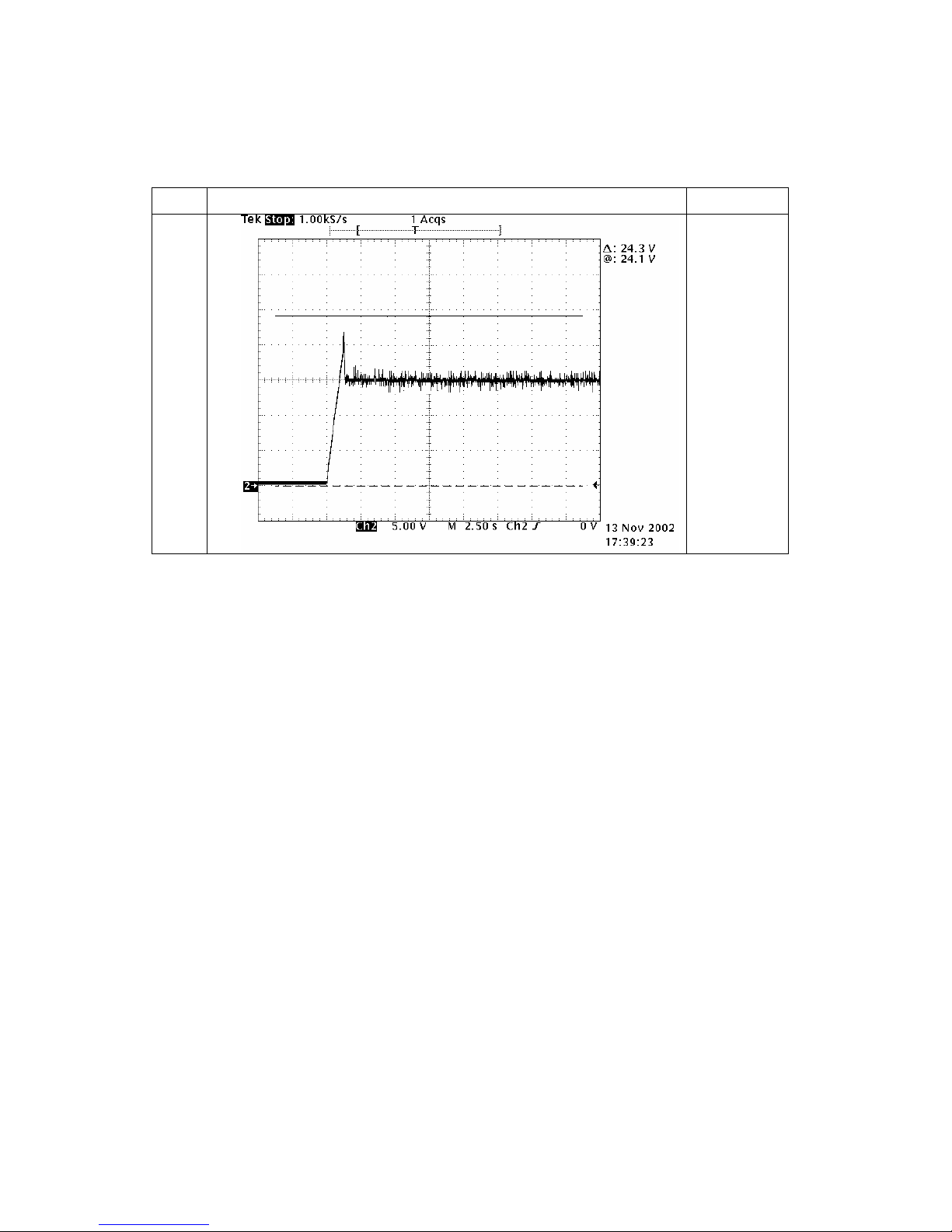
Initial Power Wave of Switching Power IC
Point
Oscilloscope Measurement
Remark
SMPS
IC PIN
3,4
- 37 -
Page 38
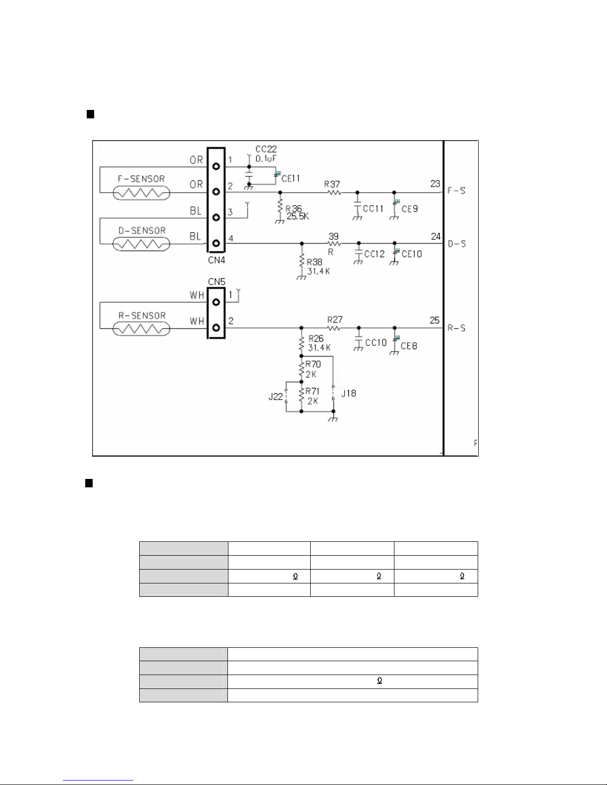
Sensors
Circuit Diagram
Function of Each Sensor
[ F-sensor ]
1) It senses the temperature of freezer compartment and controls Comp., F-fan ON / OFF.
2) How it works ;
Working Point Low ON Mid OFF High OFF
Working Temp.
-11.0 C -20.0 C - 26.0 C
Resistance
14.74 k 22.33 k 30.92 k
Sensing Voltage
3.50 V 3.00 V 2.14 V
[ D-sensor ]
-> It senses return point of defrosting heater.
Working Point Return point of defrosting heater
Working Temp.
10 C
Resistance
19.53 k
Sensing Voltage
3.1 V
- 38 -
=
.
.
=
.
.
=
.
.
=
.
.
Page 39
[ R-sensor ]
1) It senses the temperature of refrigerator compartment and controls R-fan ON / OFF.
2) How it works ;
Working Point Low ON Mid OFF High OFF
Working Temp. 2.65 C 0.3 C -1.7 C
Resistance
26.88 29.34 32.00
Sensing Voltage 2.90V 2.81V 2.74V
* In case refrigeration of refrigerator compartment is poor or insufficient though comp. and R-fan operate in
normal way ;
1) Cut J18 on M-PCB, then temp. is lowered -2 C than [Mid OFF point].
2) In addition to 1) action, cut J22 on M-PCB, then the temp. is lowered –1 C more.
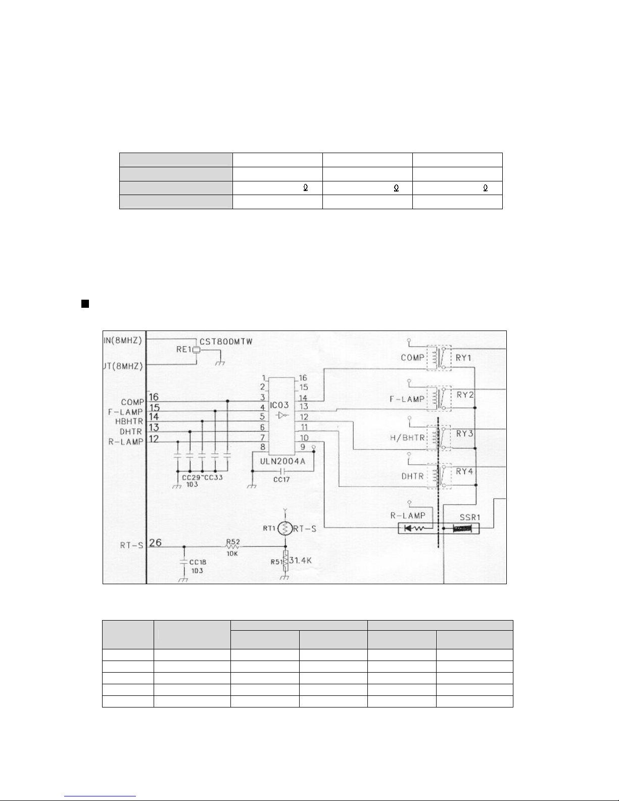
Relay Function
Circuit Diagram
How it works ;
ON Condition OFF Condition
Control Control Method
MICOM Port IC3 Output Pin MICOM Port IC03 Output Pin
COMP RELAY
# 16 3.7V # 14 0.7V # 16 0V # 14 12V
F-LAMP RELAY
# 15 3.7V # 13 0.7V # 15 0V # 13 12V
HB-HTR RELAY
# 14 3.7V # 12 0.7V # 14 0V # 12 12V
HTR RELAY
# 13 3.7V # 11 0.7V # 13 0V # 11 12V
R-LAMP RELAY or SSR
# 12 3.7V # 10 0.7V # 12 0V # 10 12V
- 39 -
k
k
k
=
.
.
=
.
.
=
.
.
=
.
.
=
.
.
=
.
.
=
.
.
=
.
.
=
.
.
=
.
.
=
.
.
=
.
.
=
.
.
=
.
.
=
.
.
=
.
.
=
.
.
=
.
.
=
.
.
=
.
.
=
.
.
=
.
.
=
.
.
=
.
.
=
.
.
=
.
.
Page 40
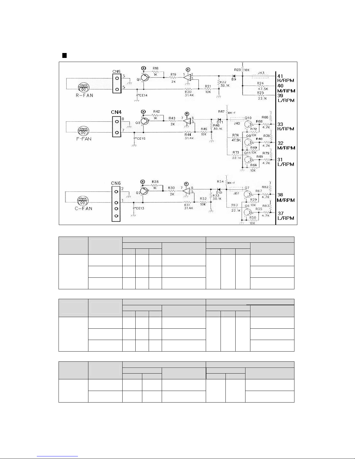
Fan Function
How It Works ;
ON Condition OFF Condition
MICOM Port MICOM Port
Control
Object
Control
Method
31 32 33
IC Collector
31 32 33
IC Collector
Low (10V)
operation
5V 0V 0V
10.35V 0V
Mid (12V)
operation
0V 5V 0V
12.19V 0V
F-FAN
High (14V)
operation
0V 0V 0V
14.38V
5V 5V 5V
0V
ON Condition OFF Condition
MICOM PORT
MICOM Port
Control
Object
Control
Method
39 40 41
IC Collector
39 40 41
IC Collector
Low (10V)
operation
0V 5V 5V
10.38V 0V
Mid (12V)
operation
5V 0V 5V
12.24V 0V
R-FAN
High (14V)
operation
5V 5V 5V
14.42V
0V 0V 0V
0V
ON Condition OFF Condition
MICOM Port MICOM Port
Control
Object
Control
Method
37 38
IC Collector
37 38
IC Collector
High (14V)
operation
0V 0V 14.54V 0V
C-FAN
Low (10V)
operation
5V 0V 10.45V
5V 5V
0V
- 40 -
Page 41
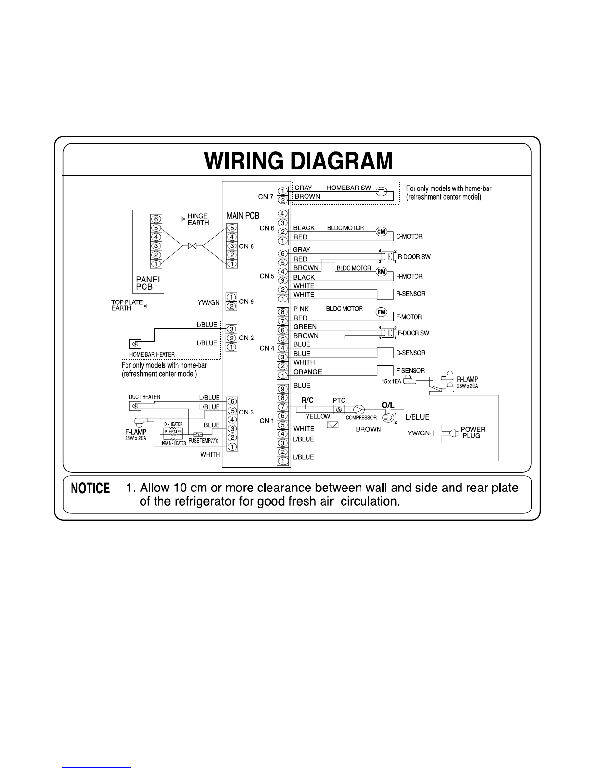
CODE:WSBS1-3
4. DIAGRAM
4-1. WIRING DIAGRAM
- 41 -
Page 42
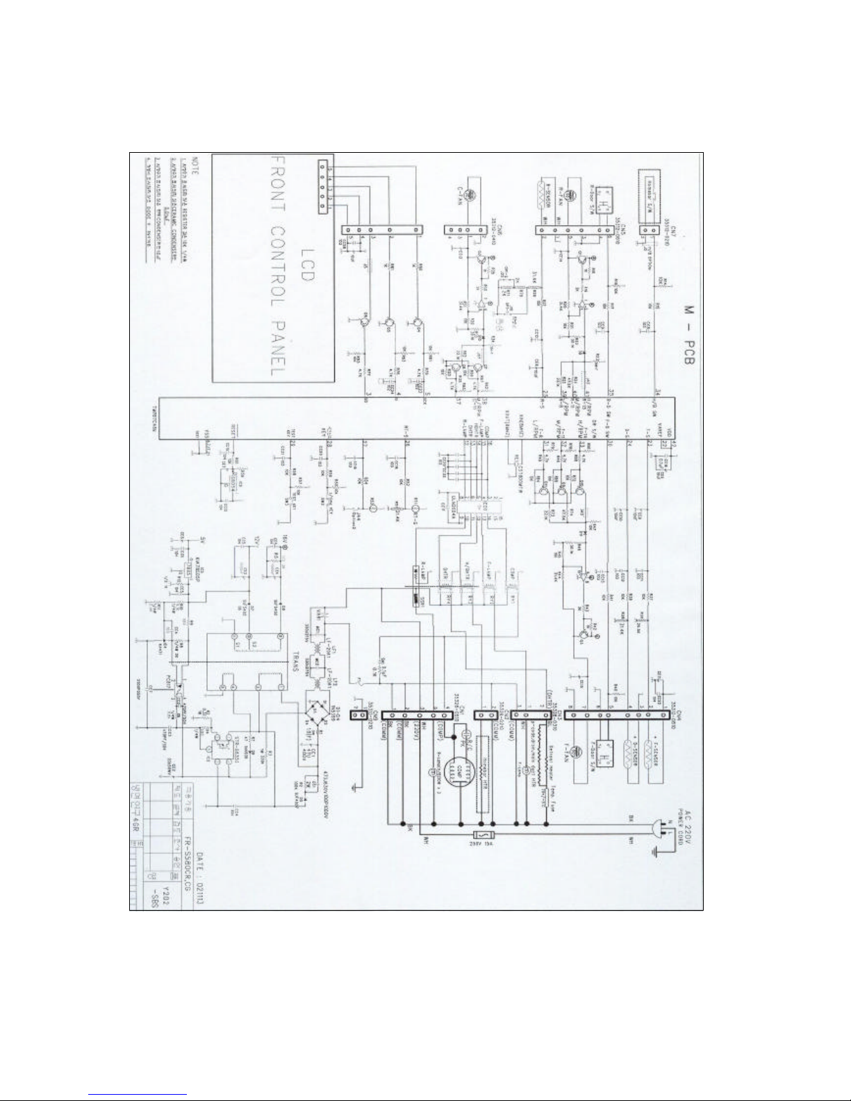
4-2. CIRCUIT WIRING DIAGRAM
Main PCB
- 42 -
Page 43
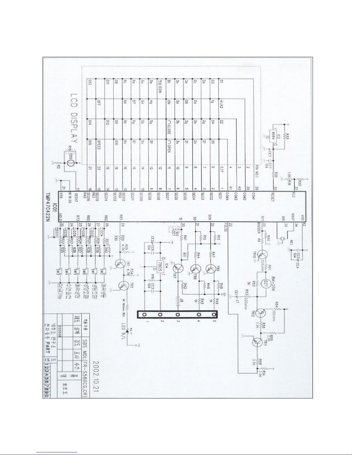
Front PCB
- 43 -
Page 44
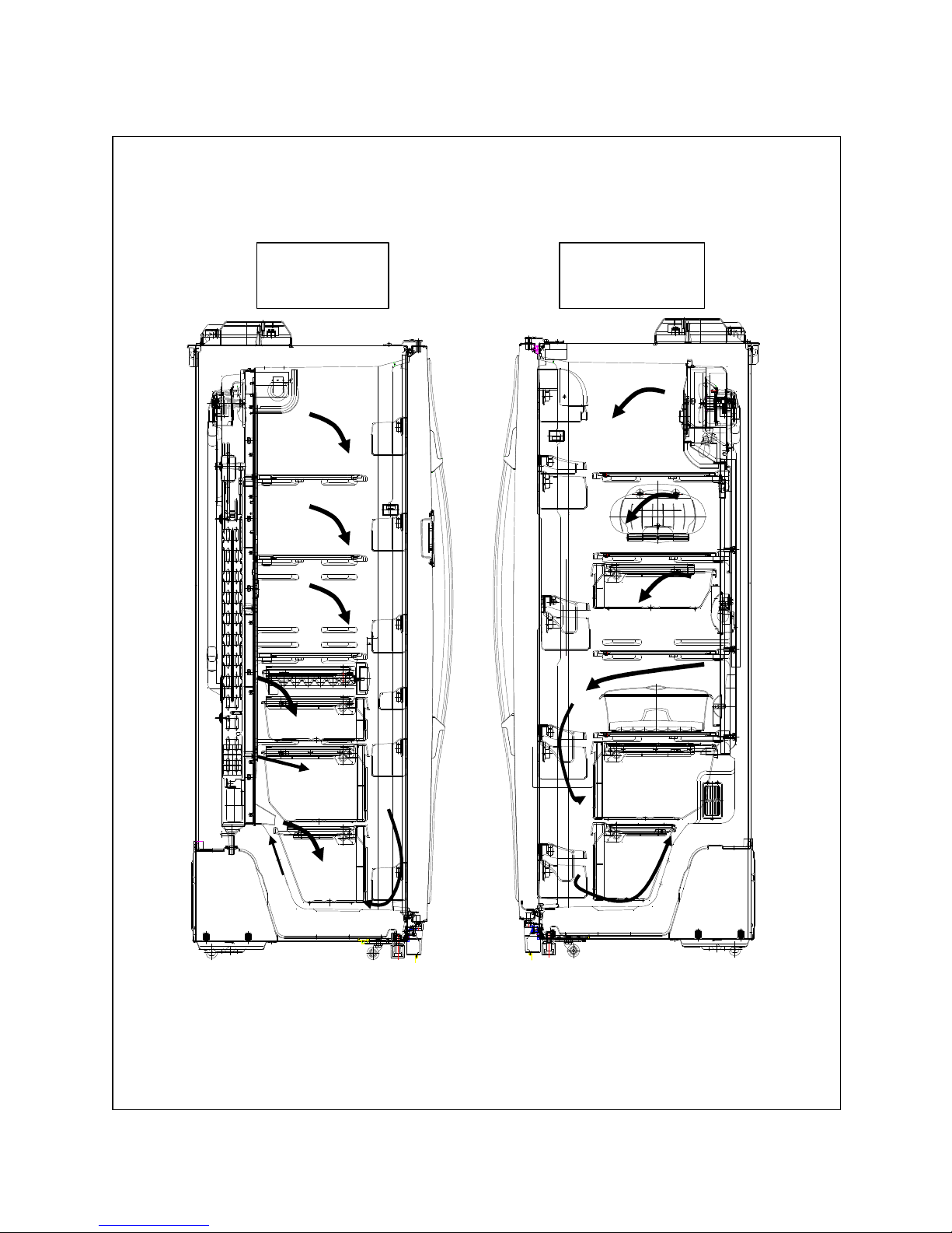
4-3. AIR FLOW DIAGRAM
- 44 -
Freezer
Compartment
Refrigerator
Compartment
Page 45
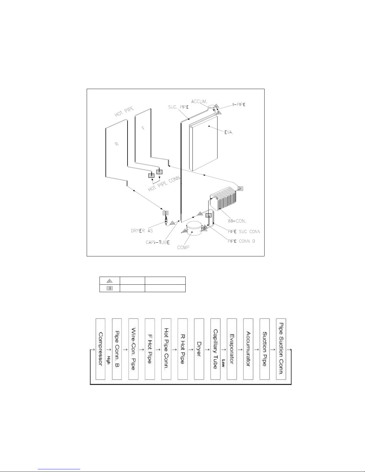
4-4. REFRIGRANT CYCLE DIAGRAM
- 45 -
Welding Points
5 % 7 points
35 % 5 points
Flow of Refrigeration Cycle
Page 46
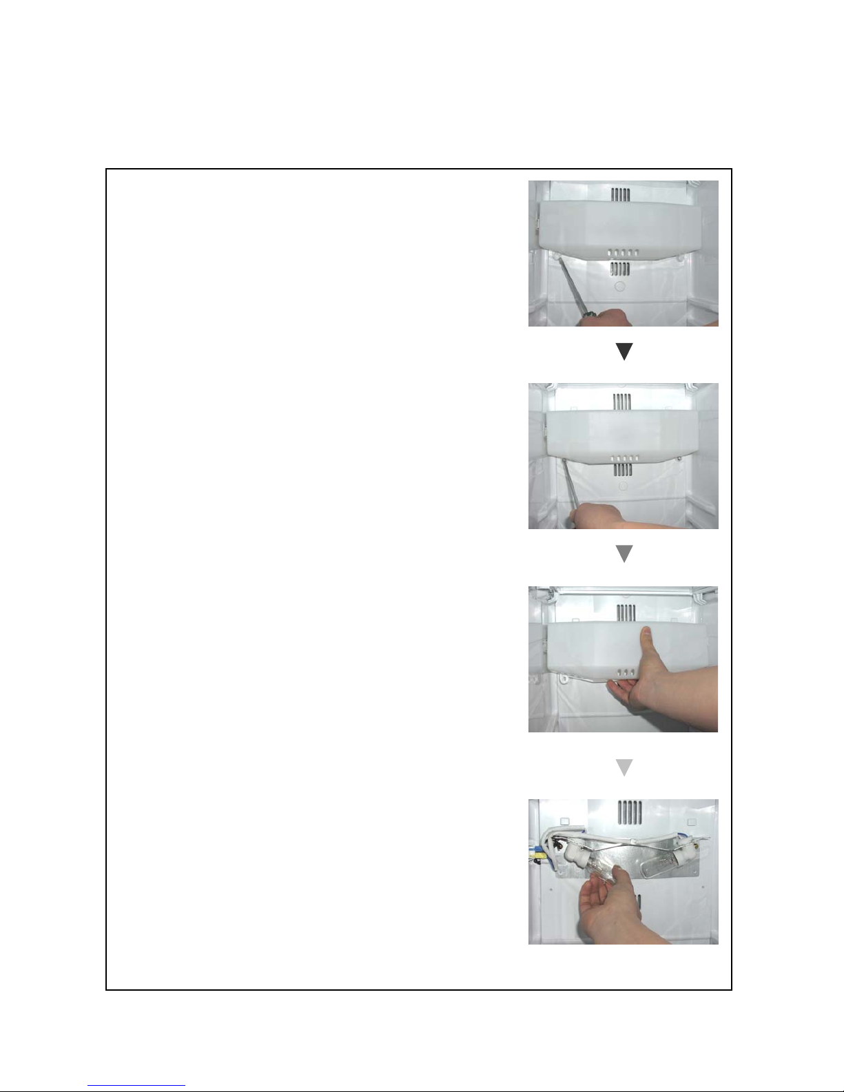
5. DISASSSEMBLY AND ASSEMBLY
5-1. Replacing Freezer Parts
1) Exchanging F-lights
* Remove screw cap with a small tip (-) driver on the
bottom of light cover
* Pull down the light cover smoothly to remove.
* Replacing F-lights.
- Assembling order is the reverse of disassembling.
- 46 -
Page 47
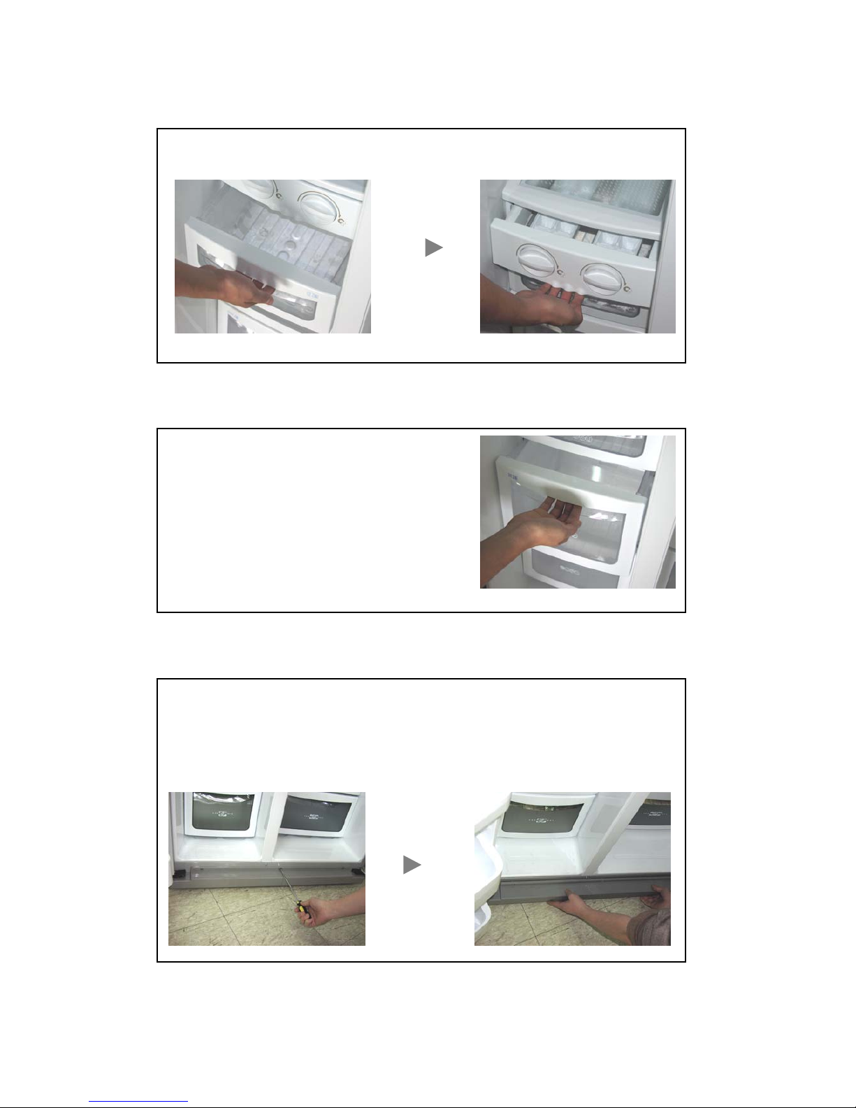
2) Ice Cubes Maker & Ice Cubes Case
3) Drying Case & Meat Case
4) Front Cover
* Pull forward Ice case and lift up a little to remove then pull Ice cubes maker.
* Pull forward and lift up a little like Ice case.
- Fruit case, vegetable case and chilled case
in Refrigerator are the same way.
* At first remove the screw caps with a (-) driver.
* Unscrew three screws with a (+) dirver.
* Assembling order is the reverse of disassembling. In order to assemble,
match front cover to the cabinet groove before screwing.
- 47 -
Page 48
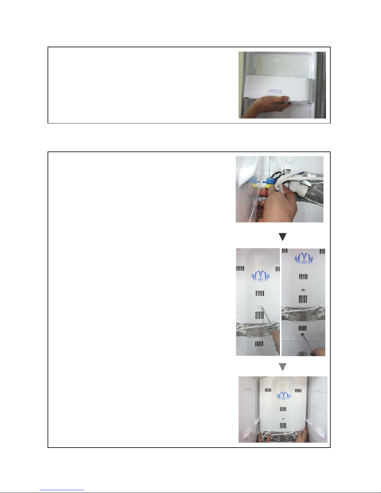
5) Freezer (Refrigerator) Pockets
6) F-Louver Parts Disassembling.
* Hold the middle and pull up slightly.
(Assembling order is the reverse of disassembling.)
- Ref Pockets are the same way.
* Open the door fully and remove the shelves.
* Remove screw cap on the bottom of light cover and
unscrew two screws with a (+) driver to separate
the light cover. [Refer to 1) Exchanging F-lights]
* Seperate F-lights housing & Heater housing
(Eva front cover) from the interior side terminals.
* Remove screw caps on F-louver A/B with a (-) driver
and then unscrew three screws with a (+) driver.
* Hold both end and pull forward smoothly.
- 48 -
Page 49
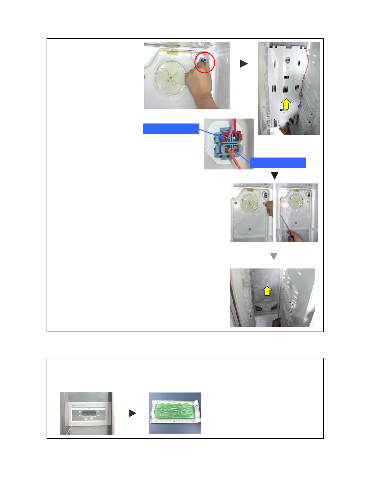
7) Front Control Pannel
냉동실 MOTER HOUSING
SENSOR HOUSING
* Separate sensor housing
on the top of F-louber C.
* Hold the bottom nose of cover and pull
forward out smoothly.
* Insert a flat tip driver into the left down groove of panel frame and snap it out smoothly.
* Remove housing from F-PCB and screws on the board to change for a new one.
* Assembling is the reverse order of disassembling.
* Separate Moter Housing and remove three screws.
* In order to disassemble F-louver C, separate hook
with a (-) driver and pull out smoothly.
* Like F-louver C, remove F-louver D.
(Assembling order is the reverse of disassembling.)
- 49 -
Page 50
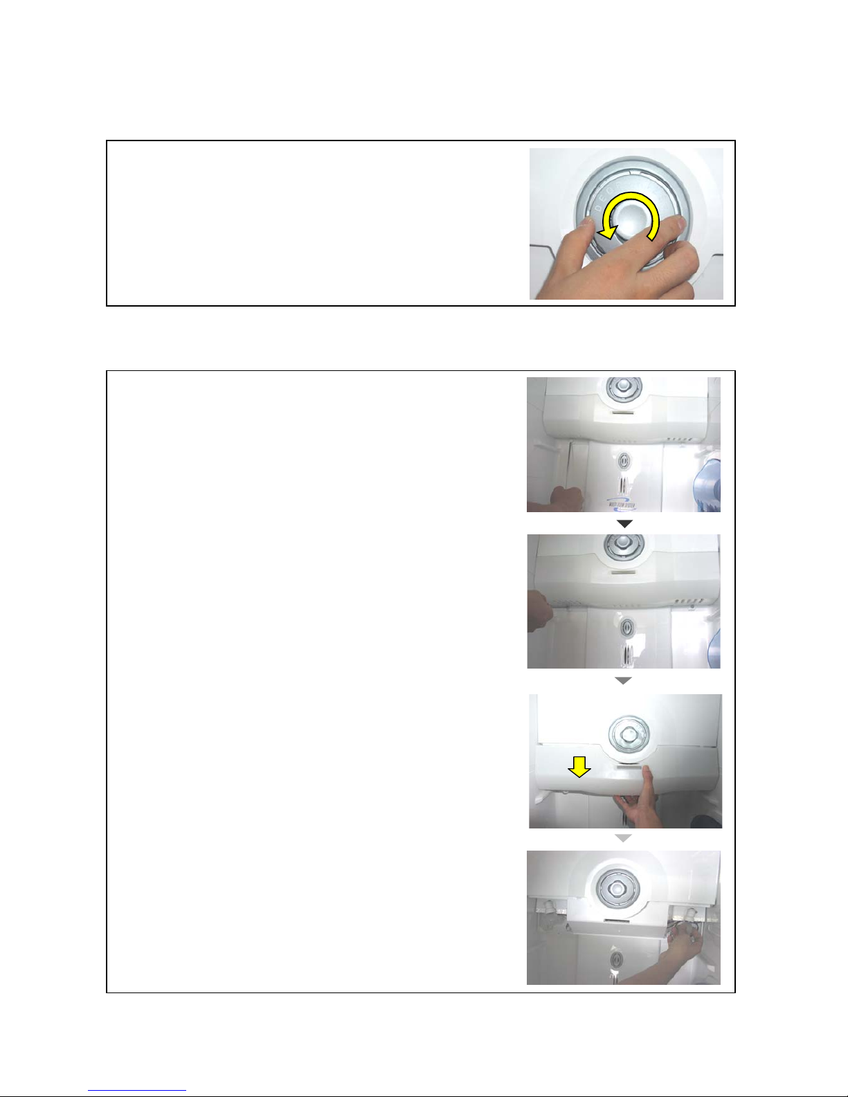
5-2. Replacing Refrigerator Parts
1) Deodorizer
2) Top R-Light
* Turn deodorizer counterclockwise.
(Assembling is the reverse order of disassembling.)
* Like F-lights, remove two screw caps at the bottom
of light cover with a (-) driver.
* Unscrew two screws with a (+) driver.
* Pull down R-light cover a little to separate the hook
and pull out forward smoothly.
* Replacing the bulb.
(Assembling is the reverse order of disassembling.)
- 50 -
Page 51
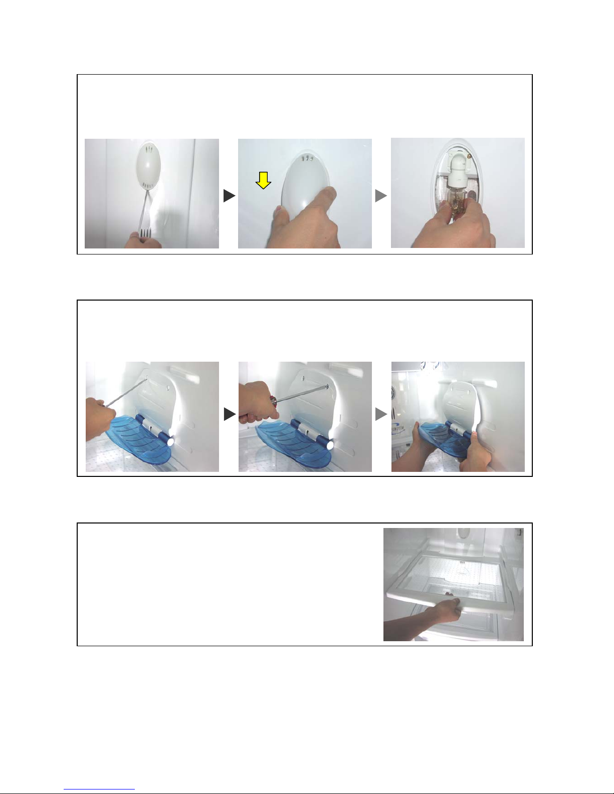
3) Refrigerator Bottom Light
4) Wine Holder
5) Shelves
* Snap out the bottom hook of light cover with a flat tip screw driver.
* Hold down the light cover to pull out.
* Change the light bulb.
(Assembling is the reverse order of disassembling.)
* Remove two screw caps on the top of Wine holder with a (-) driver.
* Unscrew 2 screws with a (+) dirver.
* Hold end of wineholder and pull up smoothly after seperating completely fixed hook.
(Assembling is the reverse order of disassembling.)
* Pull forward shelves and lift up a little to remove.
(Freezer shelves are the same way.)
- 51 -
Page 52
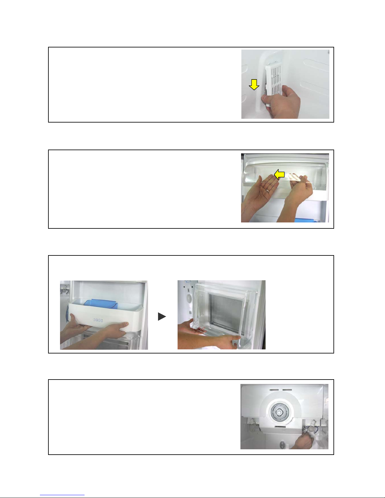
6) Return Duct Cover
7) Dairy Pocket
8) Refreshment Pocket (Only for FRS-2041)
9) Refrigerator interior parts
* Pull out the cover to arrow direction.
* Pull forward and lift up a little.
* Hold both end and pull up to remove the pocket.
* Lift up a little and then pull forward out.
* Remove foods and shelves of R-compartment.
* Remove screws caps with a tiny tip screw driver and
remove light cover screws with a (+) screw driver
(Refer to 2) Top R-Light)
* Disassemble RAMP R A HOUSING, SENSOR HOUSING
and RAMP R B HOUSING.
- 52 -
Page 53
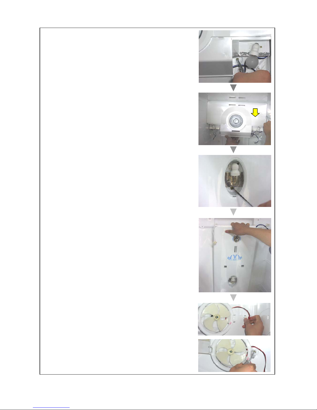
* Unscrew two screws on the left and right side of
DAMP COVER.
* Hold the bottom and right of damper to pull down
to remove.
* After removing bottom R-light cover, unscrew with a (+)
driver. (Refer to 3) Refrigerator Bottom Light)
* Hold top of the MULT DUCT COVER AS and pull forward
to remove.
* Remove FAN HOUSING on the right side.
(Unscrew two screws on the FIXTURE MOTOR B.)
* Assembling is the reverse order of disassembling.
When assembling, be careful not to disturb Fan.
- 53 -
Page 54
6-1. Installation Preparation
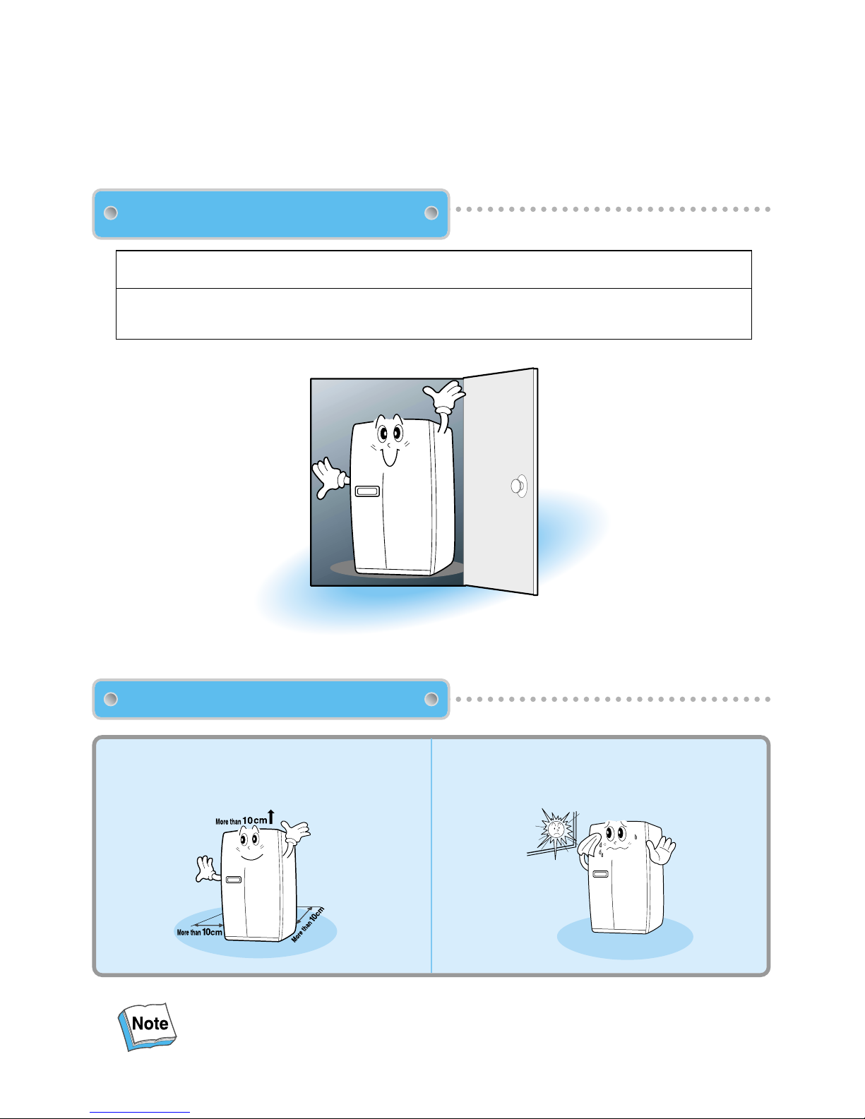
Dimensions (Including Door Handles)
Sufficient space from refrigerator back to the
wall for free air ventilation
Avoid direct sunlight.
Once the installation place is ready follow the installation instructions.
If surround temperature of refrigerator is low (below 5C), foods can be frozen or the refrigerator can work
in an abnormal way.
Check if the refrigerator can pass
a doorway or enter a door first.
Find a suitable place to install.
6. INSTALLATION GUIDE
- 54 -
(Width X Depth X Height)
928mm X 816mm X 1808mm [FRS-2021 / FRS-2041]
928mm X 896mm X 1808mm [FRS-2421 / FRS-2441]
Page 55
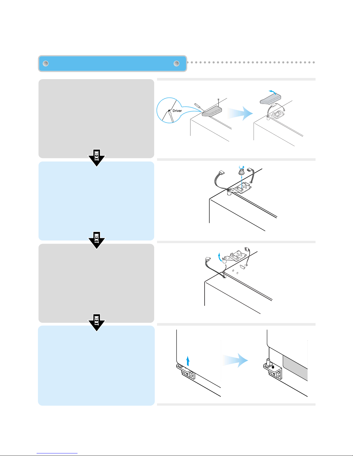
Remove front bottom cover first, if it is attached.
!
!
@
!
@
1
Unscrew top hinge cover with a screw driver.
Insert a thin screw driver into the side
groove of the cover to remove.
2
Turn top hinge fastener counterclockwise
3~4 times.
Disconnect the harness wires.
3
Lift up the front of hinge to remove. (After
the hinge is removed the door can fall
4
Lift the door straight up to remove.
Removing Freezer Door
6-2. If the refrigerator can not enter the door, follow these steps.
- 55 -
!
down forward. Be careful!)
Page 56
!
@
!
@
1
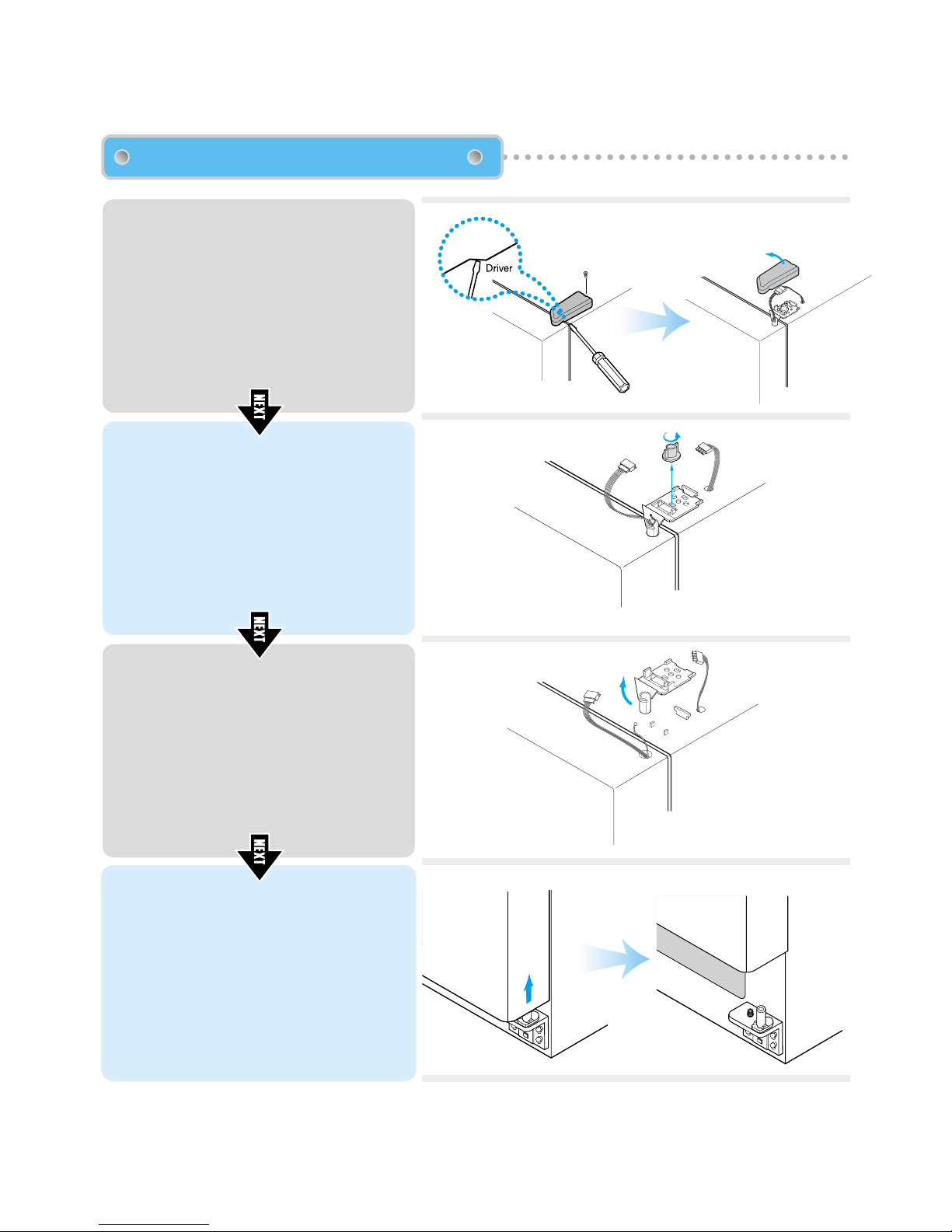
Unscrew top hinge cover with a screw
driver.
Insert a thin screw driver into the side
groove of the cover to remove.
2
Turn top hinge fastener counterclockwise
3~4 times.
Disconnect harness wires.
3
Lift up the front of hinge to remove. (After
the hinge is removed the door can fall
down forward. Be careful !)
4
Lift the door straight up to remove.
Removing Refrigerator Door
- 56 -
!
Page 57
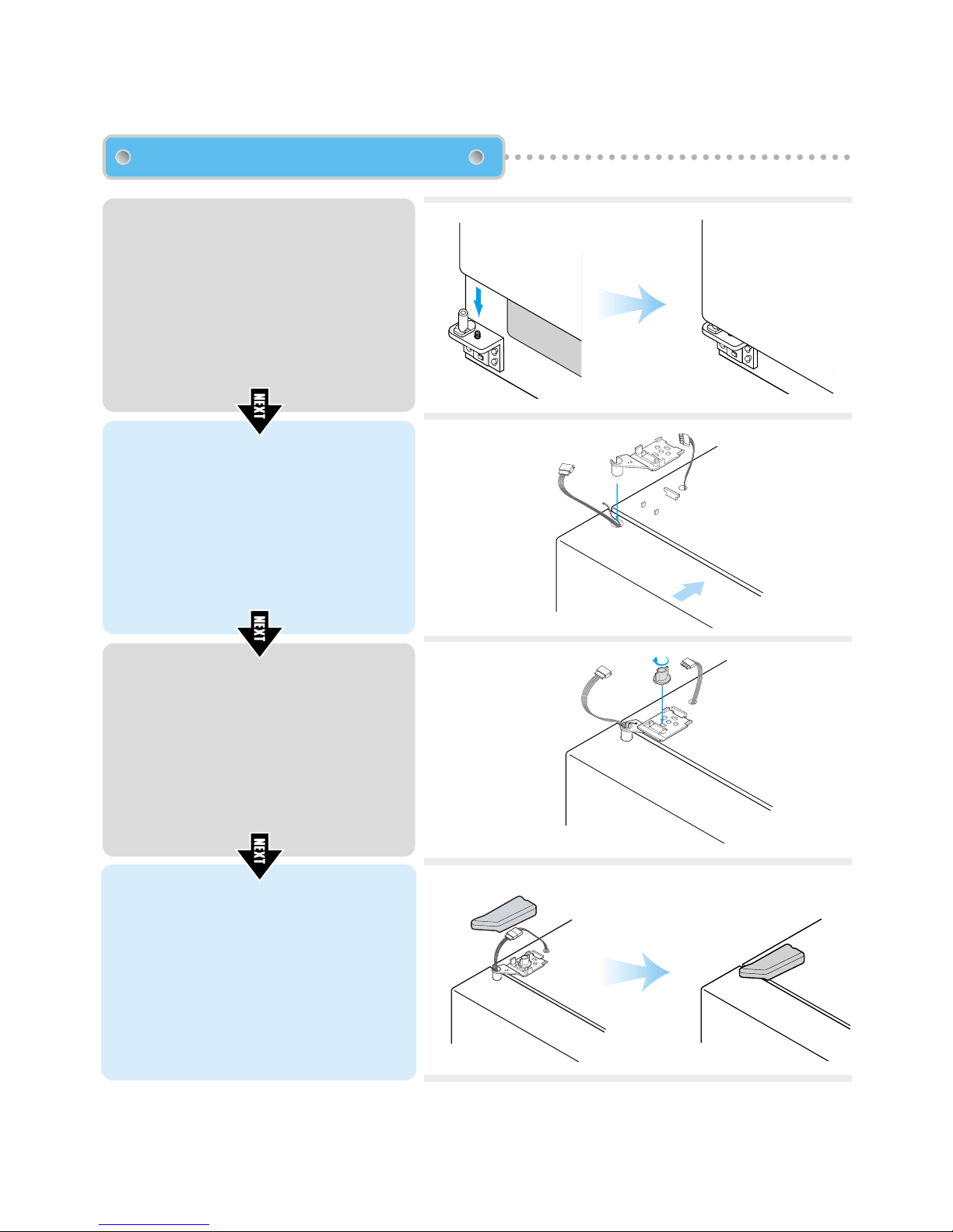
!
@
!
@
!
@
Replacing Freezer Door
- 57 -
!
1
Insert the bottom hole of freezer door
straight to the bottom hinge pin.
2
Let the top of door close to the cabinet and
insert the top hinge pin to the top hole of
freezer door.
( Insert the back of hinge to the groove of
protrusion first, then front to the top hole of
door.)
3
Turn the hinge fastener tightly to the end.
Connect harness wirings and screw ground
wire.
4
Click and screw the top hinge cover.
Page 58
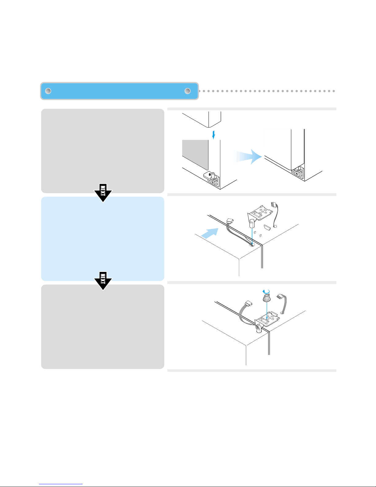
Replacing Refrigerator Door
- 58 -
!
@
!
@
!
@
!
1
Insert the bottom hole of refrigerator door
straight to the bottom hinge pin.
2
Let the top of door close to the cabinet and
insert the top hinge pin to the top hole of
freezer door.
( Insert the back of hinge to the groove of
protrusion first, then front to the top hole of
door.)
3
Turn the hinge fastener tightly to the end.
Connect harness wirings and screw ground
wire.
Click and screw the top hinge cover.
Page 59
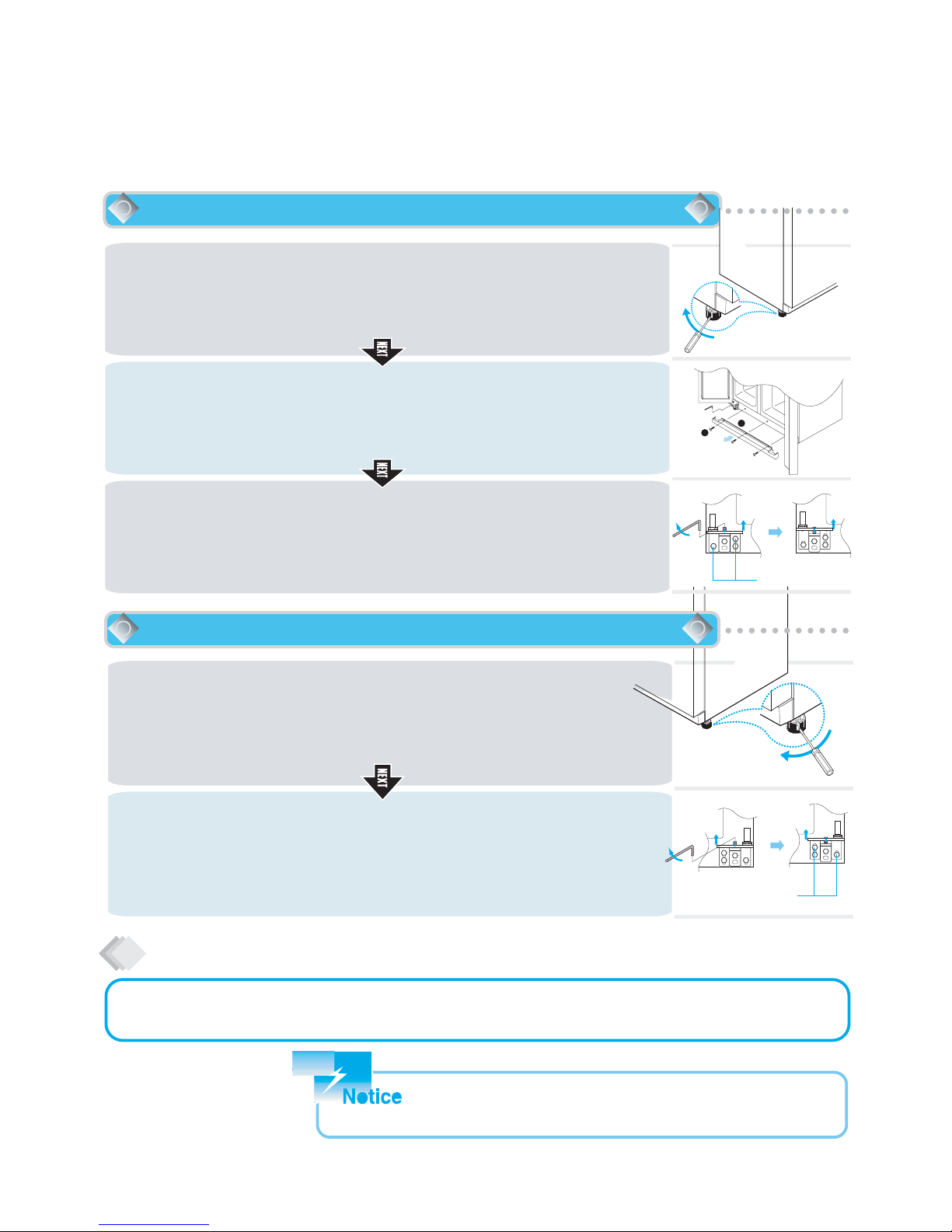
1
Insert a screw driver (flat tip) into a groove of the right wheel (bottom of refrigerator) and
turn it clockwise until the door is balanced. (clockwise to raise refrigerator door ;
counterclockwise to lower)
Unless the refrigerator door is balanced by step 1, then follow the next steps.
2
Loosen 3 hinge bolts(2 on the left + 1 on the right) a little. (Do not unfasten them completely)
Insert a hexagonal wrench into the groove of adjusting nut and turn clockwise until the
door is level.
3
Once the door is balanced, fasten the hinge bolts tightly.
In case refrigerator door is lower than freezer door...
In case refrigerator door is lower than freezer door...
Hinge Bolt
After installation and/or door leveling, fasten front cover with screws.(Remove the screws on the front bottom panel first.
Click and screw the cover)
Front Cover
Refrigerator must be level in order to maintain optimal performance and desirable front appearance.
(If the floor beneath the refrigerator is uneven, freezer and refrigerator doors look unbalanced.)
1
Insert a screw driver (flat tip) into a groove of the left wheel (bottom of freezer) and turn it
clockwise until the door is balanced. (clockwise to raise freezer door ; counterclockwise
to lower)
Unless the freezer door is balanced by step 1, then follow the next steps.
2
Open the doors, unscrew the front cover and remove, if it is attached.
3
Loosen 3 hinge bolts(1 on the left + 2 on the right) a little. (Do not unfasten them
completely) Insert a hexagonal wrench into the groove of adjusting nut and turn
clockwise until the door is level.
4
Once the door is balanced, fasten the hinge bolts tightly and screw the front cover.
In case freezer door is lower than refrigerator door...
The front of refrigerator needs to be higher just a little than the back for easy door
closing, but if the wheel is raised too much for door balance, i.e. front of refrigerator
is too higher than the back, it can be difficult to open the door.
Hinge Bolt
6-3. Refrigerator Leveling & Door Adjustment (If needed.)
- 59 -
-
Page 60
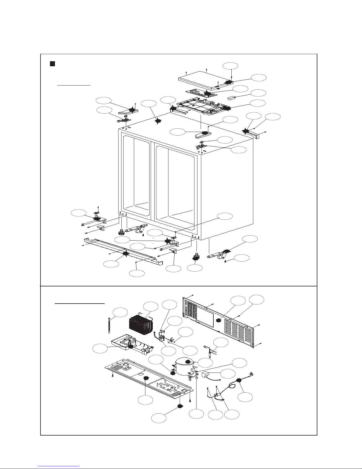
15
16
13
14
10
9
12
11
27
22
24
21
25
23
26
18
17
20
19
4
3
2
6
8
7
1
7. EXPLODED VIEW AND PARTS LIST
7-1. Total Exploded View
FRS-2021 / FRS-2421
- 60 -
CABINET
30
36
32
31
47
34
35
38
37
39
33
29
46
45
40
44
42
41
49
43
48
MECH ROOM
Page 61
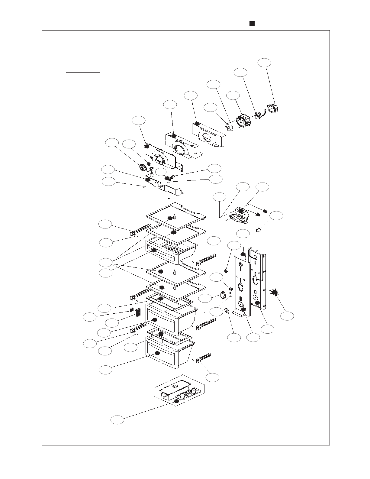
FRS-2021 / FRS-2421
- 61 -
R ROOM
70
66
72
87
73
76
71
86
77
78
93
79
74
75
90
88
91
84
85
89
64
63
69
67
62
60
82
83
68
92
80
81
51
50
53
52
59
57
56
58
54
55
61
Page 62
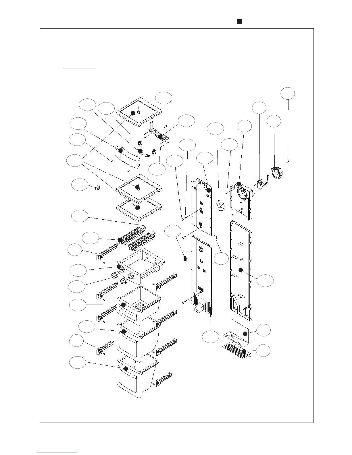
FRS-2021 / FRS-2421
- 62 -
F ROOM
120
113
117
121
122
124
104
119
103
102
125
114
115
111
108
110
123
118
112
109
105
107
100
101
106
94
67
75
95
96
97
98
99
Page 63
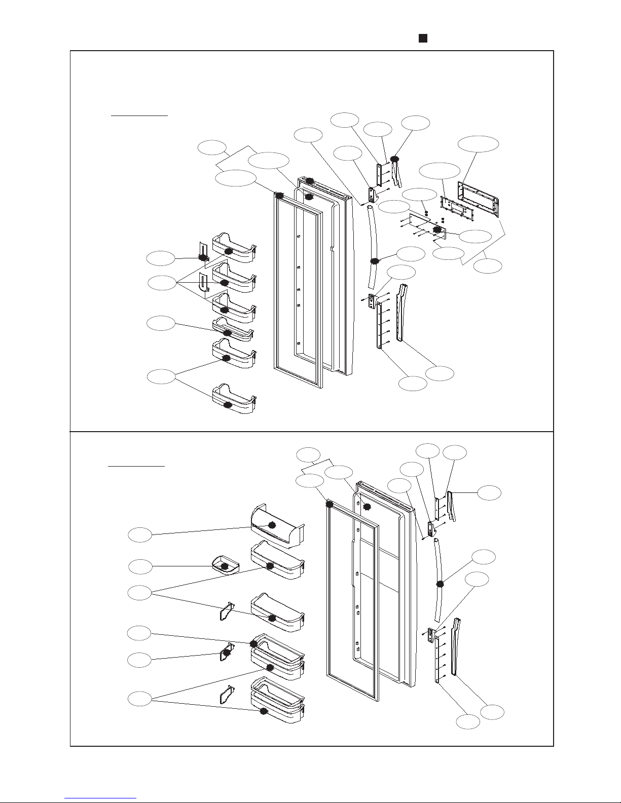
FRS-2021 / FRS-2421
- 63 -
F DOOR
129
129-1
135
129-2
132
141-3
136
141-4
138
141-1
139
141-2
141
141-5
133
141-6
126
153-1
127
128
127
153-2
134
137
140
147
137
133
136
148
140
135
132
149
134
153
138
150
151
152
139
R DOOR
Page 64
15
16
13
14
10
9
12
11
27
22
24
21
25
23
26
18
17
20
19
4
3
2
6
8
7
1
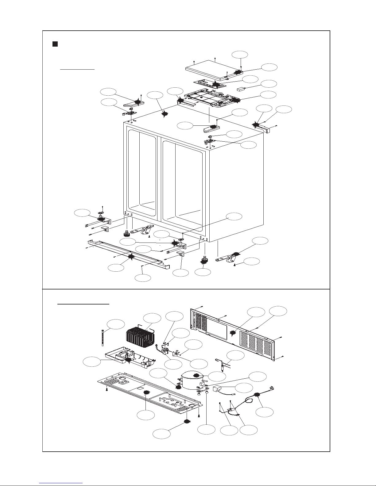
FRS-2041 / FRS-2441
- 64 -
CABINET
30
36
32
31
47
34
35
38
37
39
33
29
46
45
40
44
42
41
49
43
48
MECH ROOM
Page 65
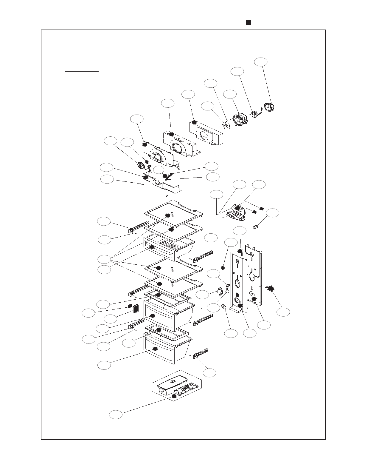
FRS-2041 / FRS-2441
- 65 -
R ROOM
70
66
72
87
73
76
71
86
77
78
93
79
74
75
90
88
91
84
85
89
64
63
69
67
62
60
82
83
68
92
80
81
51
50
53
52
59
57
56
58
54
55
61
Page 66
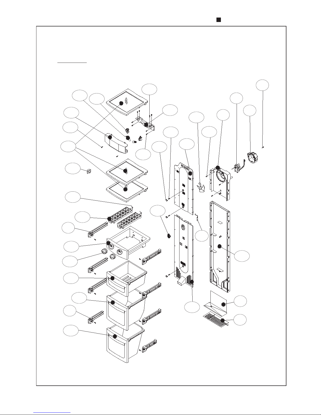
FRS-2041 / FRS-2441
- 66 -
F ROOM
120
113
117
121
122
124
104
119
103
102
125
114
115
111
108
110
123
118
112
109
105
107
100
101
106
94
67
75
95
96
97
98
99
Page 67
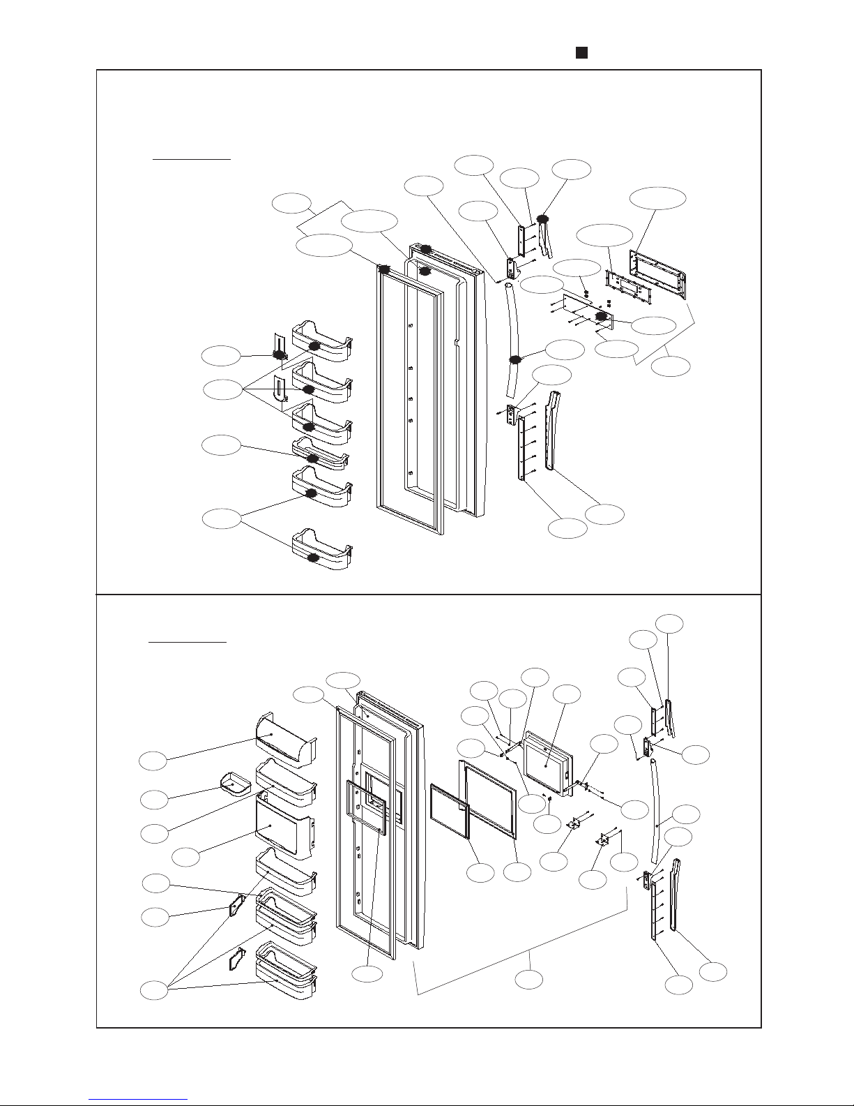
FRS-2041 / FRS-2441
- 67 -
F DOOR
129
129-1
135
129-2
132
141-3
136
141-4
138
141-1
139
141-2
141
141-5
133
141-6
126
127
128
127
134
137
140
R DOOR
155-1
155-3
155-2
148
149
150
151
152
153
154
163
141
138
135
162
155
172
161
134
159
160
169
164
173
133
171
166
136
140
139
137
170
168
167
165
Page 68
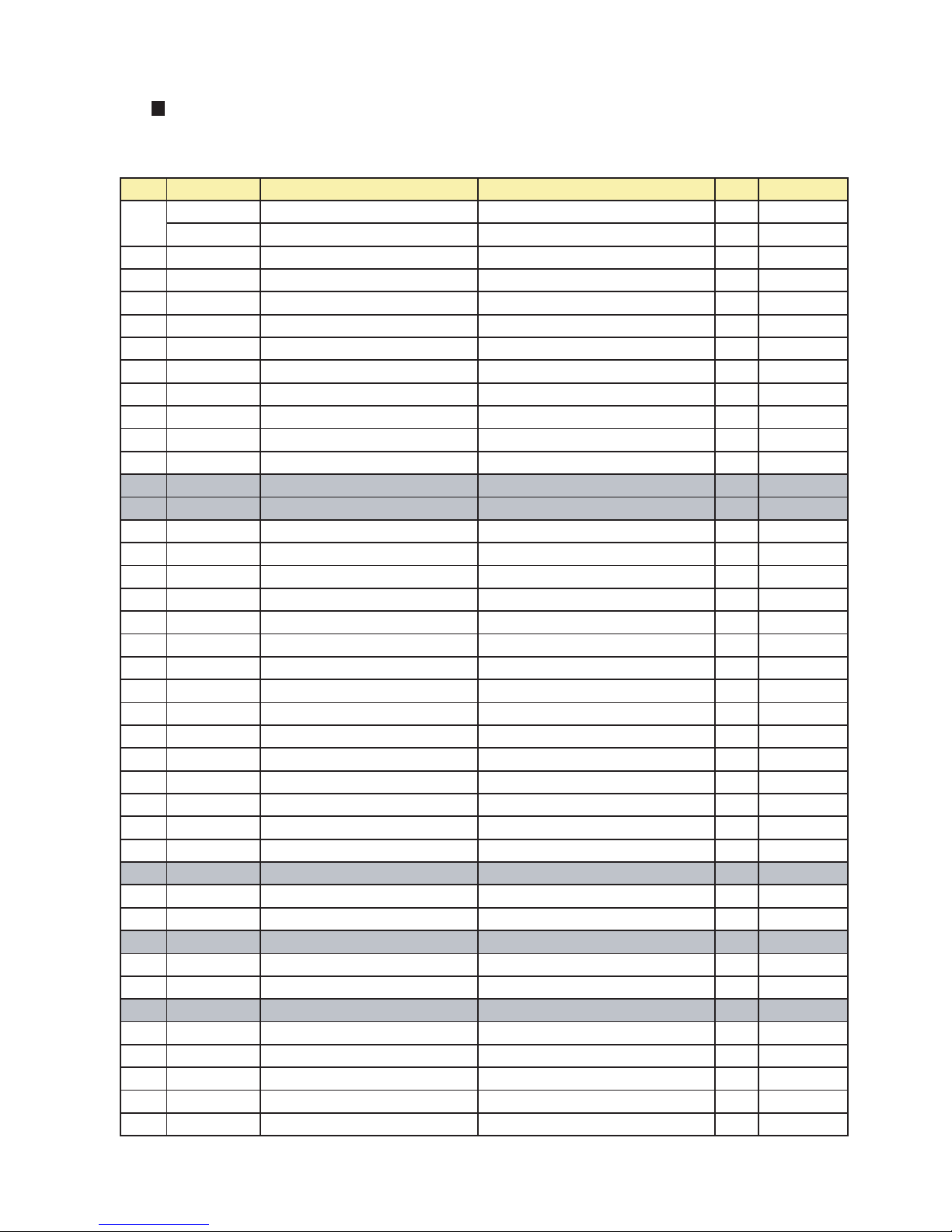
NO PART CODE PART NAME PART DESCRIPTION Q'TY REMARK
3000003600 ASSY CAB URT 1 FRS-2021
3000025700 ASSY CAB URT FR-S690CG/CR FRS-2421
2 3012917600 HINGE *T *R AS PO T3.0 1
3 3012918500 HINGE *T *L AS PO T3.0 1
4 3012013000 FIXTURE *T HI PP 2
6 3011472400 COVER HI *T *R PP 1
7 3011472300 COVER HI *T *L PP 1
8 7112401211 SCREW TAPPING T1 TRS 4 x 12 MFZN 2
9 3012601301 HANDLE CAB COVR *R PP 1
10 3012601201 HANDLE CAB COVR *L PP 1
11 7112401211 SCREW TAPPING T1 TRS 4 x 12 MFZN 1
12 3010533400 BOX MAIN PCB PP 1
13 CAPACITOR RUN 1
14 PCB MAIN AS 1
15 3011472610 COVER MAIN PCB BOX PP 1
16 7112401211 SCREW TAPPING T1 TRS 4 x 12 MFZN 1
17 3012917810 HINGE *U *R AS PO T5.0+PAINTING 1
18 3012917710 HINGE *U *L AS PO T5.0+PAINTING 1
19 3012513300 GUIDE *U HINGE *U POM 2
20 7002501611 SCREW MACHINE TRS M5 x 16 MFZN 2
21 3016001240 SPECIAL BOLT *T 6 x 22 SWCH22A(YL) 8
22 3015306700 SUPPORTER *U HI AS PO T5.0 2
23 3012104400 FOOT ADJUST AS 2
24 3016501200 CASTER TURN AS TURN CASTER 2
25 3016001240 SPECIAL BOLT *T 6 x 22 SWCH22A(YL) 2
26 3011471010 COVER CAB BRKT PP 1
27 7142401611 SCREW TAPPING T2 TRS 4 x 16 MFZN 3
29 3010326700 BASE COMP AS SBHG T1.2 1
30 3016003300 SPECIAL BOLT T2 M6.5 x 20 4EA 4
31 CORD POWER AS 1
32 7112401211 SCREW TAPPING T1 TRS 4 x 12 MFZN 1
33 7051401065 SCREW MACHINE PAN 4 x 10 SW BSNI 1
34 COMP 1
35 3016002500 SPECIAL WASHER SK-5 T0.8 4
36 3010101440 ABSORBER COMP AS 4
38 RELAY STARTING 1
39 3011113500 CASE VAPORI PP + CTALC 1
40 3013201700 HOSE DRAIN PEHD 1
41 3014413730 PIPE WICON AS 1
42 3010102100 ABSORBER C MOTR NR FRB-5350NT 1
43 3012004400 FIXTURE C MOTR SUS 1
1
- 68 -
7-2. Total Parts List
FRS-2021 / FRS-2421
✔ Caution:
In this Service Manual, some parts can be changed for improving, their performance without notice in the parts list. So, if you need the
latest parts information, please refer to PPL(Parts Price List) in Service information Center(http://svc.dwe.co.kr)
Page 69
NO PART CODE PART NAME PART DESCRIPTION Q'TY REMARK
44 3015911500 MOTOR C FAN AS DC12V 2.5W 1
45 3011802200 FAN ABS (O.D.)3.17 x D110 1
46 3011200500 CLAMP FAN SUS 304 1
47 3016806900 DRYER AS XH-9 15g 1
48 3011474710 COVER MACH ROOM AS SBHG T0.4 1
49 7112401211 SCREW TAPPING T1 TRS 4 x 12 MFZN 6
50 3012007800 FIXTURE MOTOR A PP 1
51 3015911400 MOTER R FAN AS 1
52 3012007900 FIXTURE MOTOR B HIPS 1
53 7122401211 SCREW TAPPING T2S TRS 4 x 12 MFZN 2
54 3011802200 FAN ABS (O.D.)3.17 x D110 1
55 3013344200 INSU DAMP B F-PS 1
56 3013344100 INSU DAMP A F-PS 1
57 3011471200 COVER DAMP HIPS 1
58 3018701800 DEO ANTI AS 1
59 3011471310 COVER DEO ABS 1
60 3017905300 SOCKET R LAMP AS 2
61 7121300811 SCREW TAPPING T2S PAN 3 x 8 1
62 LAMP R A 2
63 3015507900 WINDOW R LAMP A MIPS 1
64 3016002710 SPECIAL SCREW 4 x 12 2
3017827300 SHELF R A AS GLASS + HIPS 4 FRS-2021
3017831900 SHELF R A AS FRAME + SHELF + FIXTURE 4 FRS-2421
67 3012514500 GUIDE CASE A *L AS ABS 2
68 3012514600 GUIDE CASE A *R AS ABS 2
69 7142401611 SCREW TAPPING T2 TRS 4 x 16 MFZN 4
3011171200 CASE CHILD AS GPPS + HIPS 1 FRS-2021
3011177700 CASE CHILD AS CASE + FRAME STAMPING 1 FRS-2421
3011473100 COVER VEGETB CASE A GPPS 1 FRS-2021
3011485300 COVER VEGETB CASE A GPPS 1 FRS-2421
72 3018701800 DEO ANTI AS 1
73 3011472900 COVER RETURN DUCT HIPS 1
3011172000 CASE VEGETB A AS GPPS + HIPS 1 FRS-2021
3011178200 CASE VEGETB A AS CASE + FRAME STAMPING 1 FRS-2421
75 3012514700 GUIDE CASE B *L AS ABS 1
76 3012514800 GUIDE CASE B *R AS ABS 1
77 7142401611 SCREW TAPPING T2 TRS 4 x 16 MFZN 2
3011473200 COVER VEGETB CASE B GPPS 1 FRS-2021
3011485400 COVER VEGETB CASE B GPPS 1 FRS-2421
3011172100 CASE VEGETABLE B AS GPPS + HIPS 1 FRS-2021
3011178300 CASE VEGETABLE B AS CASE + FRAME STAMPING 1 FRS-2421
80 3017827500 SHELF WINE AS ABS 1
81 3016002710 SPECIAL SCREW 4 x 12 2
82 3010903200 CAP SCREW PE 2
83 3018124000 SWITCH LAMP SP201R-7DR 1
74
78
79
66
70
71
- 69 -
Page 70
NO PART CODE PART NAME PART DESCRIPTION Q'TY REMARK
84 3017100500 FLAP MULT DUCT PP 1
85 3013345000 INSU MULT DUCT AS F-PS 1
86 3011472700 COVER MULT DUCT HIPS 1
87 3013408100 KNOB MULT DUCT ABS 1
88 3017905310 SOCKET R LAMP AS 250V 1A 1
89 LAMP R B 1
90 3015508000 WINDOW R LAMP B MIPS 1
91 3011473000 COVER SENS ABS 1
92 3014805400 SENSOR R AS PBN-438 1
93 3011171300 CASE EGG AS GPPS 1
94 3012514200 GUIDE DRN GA 1
95 HEATER DRN GUIDE AS 1
96 7112401211 SCREW TAPPING T1 TRS 4 x 12 MFZN 1
97 3012007800 FIXTURE MOTOR A PP 1
98 3015911300 MOTOR F FAN AS DC12V 2.5W 1
99 3018914400 LOUVER F C PP 1
100 7142401611 SCREW TAPPING T2 TRS 4 x 16 MFZN 3
101 3011802200 FAN ABS (O.D.)3.17 x D110 1
102 3018914900 LOUVER F D AS PP 1
103 3014805300 SENSOR F AS PT-38 1
104 3018914700 LOUVER F B AS HIPS 1
105 3018914610 LOUVER F A AS HIPS 1
106 7142401611 SCREW TAPPING T2 TRS 4 x 16 MFZN 3
107 3010924600 CAP F LUVR HIPS 3
108 3011473000 COVER SENS ABS 1
109 3014559510 PLATE LAMP F SBHG T0.8 1
110 3017905200 SOCKET F LAMP AS 2
111 3013602000 LAMP F/R 240V 25W 2
112 7121300811 SCREW TAPPING T2S PAN 3X8 MFZN 4
113 7112401211 SCREW TAPPING T1 TRS 4 x 12 MFZN 4
114 3015507710 WINDOW F LAMP MIPS 1
115 3016002710 SPECIAL SCREW 4 x 12 2
117 3017827100 SHELF F A AS GLASS + HIPS 3
118 3018124000 SWITCH LAMP SP201R-7DR 1
119 3015101300 SPRING ICING CASE STS304WPB 2
3011170600 CASE ICING PP 2 FRS-2021
3011177300 CASE ICING PP 2 FRS-2421
3012203800 FRAME ICE MAKER ABS 1 FRS-2021
3012205300 FRAME ICE MAKER ABS 1 FRS-2421
3013408000 KNOB ICEING CASE HIPS 2 FRS-2021
3013409300 KNOB ICEING CASE HIPS 2 FRS-2421
3011171800 CASE ICE AS GPPS + HIPS 1 FRS-2021
3011178000 CASE ICE AS GPPS + HIPS 1 FRS-2421
3011171400 CASE F A AS GPPS + HIPS 1 FRS-2021
3011177800 CASE F A AS GPPS + HIPS 1 FRS-2421
121
122
123
124
120
- 70 -
Page 71
NO PART CODE PART NAME PART DESCRIPTION Q'TY REMARK
3011171500 CASE F B AS GPPS + HIPS 1 FRS-2021
3011177900 CASE F B AS GPPS + HIPS 1 FRS-2421
126 3012516000 GUIDE F POCKET PP 2
127 3019019100 POCKET F *U HIPS 5
128 3019019000 POCKET F *T HIPS 1
129 3000018700 ASSY F DR FRS-2021 1
129-1 3012314200 GASKET F DR AS PVC 1
129-2 3000003700 ASSY F DR URT 1
132 3011623800 DECO HNDL *T ABS + PLATING 1
133 3012628500 HANDLE AL 1
134 3011613900 DECO HNDL *U ABS + PLATING 1
135 3016031700 SPECIAL SCREW 2
136 3010326100 BASE DECO COVER *T HIPS 1
137 3010326200 BASE DECO COVER *U HIPS 1
138 7112401211 SCREW TAPPING T1 TRS 4 x 12 MFZN 8
139 3011472100 COVER HNDL DECO *T ABS 1
140 3011472200 COVER HNDL DECO *U ABS 1
141 3011747510 COVER F PCB AS FRS-2021 1
141-1 7111300811 SCREW TAPPING T1 PAN 3 x 8 MFZN 7
141-2 30143B4110 PCB F AS 1
141-3 3016302600 BUTTON CONTL B ABS 2
141-4 3016303100 BUTTON CONTL A ABS + 4
141-5 3015507800 WINDOW F PCB ABS 1
141-6 3011471600 COVER F PCB ABS + COATING 1
147 3019019400 POCKET DAIRY AS GPPS + HIPS 1
148 3019019300 POCKET R *S GPPS 1
149 3019019800 POCKET R *M HIPS 2
150 3012514100 GUIDE R POKT HIPS 2
151 3012513400 GUIDE BOTL PP 2
152 3019019200 POCKET R HIPS 2
153 3000018800 ASSY R DR FRS-2021 1
153-1 3012314500 GASKET R DR AS PVC 1
153-2 3000003800 ASSY R DR URT 1
125
- 71 -
means that you're recommended to refer to the
No. 2-2 "Eletric Parts".
Page 72
NO PART CODE PART NAME PART DESCRIPTION Q'TY REMARK
3000003600 ASSY CAB URT 1 FRS-2041
3000025700 ASSY CAB URT FR-S690CG/CR FRS-2441
2 3012917600 HINGE *T *R AS PO T3.0 1
3 3012918500 HINGE *T *L AS PO T3.0 1
4 3012013000 FIXTURE *T HI PP 2
6 3011472400 COVER HI *T *R PP 1
7 3011472300 COVER HI *T *L PP 1
8 7112401211 SCREW TAPPING T1 TRS 4 x 12 MFZN 2
9 3012601301 HANDLE CAB COVR *R PP 1
10 3012601201 HANDLE CAB COVR *L PP 1
11 7112401211 SCREW TAPPING T1 TRS 4 x 12 MFZN 1
12 3010533400 BOX MAIN PCB PP 1
13 CAPACITOR RUN 1
14 PCB MAIN AS 1
15 3011472610 COVER MAIN PCB BOX PP 1
16 7112401211 SCREW TAPPING T1 TRS 4 x 12 MFZN 1
17 3012917810 HINGE *U *R AS PO T5.0+PAINTING 1
18 3012917710 HINGE *U *L AS PO T5.0+PAINTING 1
19 3012513300 GUIDE *U HINGE *U POM 2
20 7002501611 SCREW MACHINE TRS M5 x 16 MFZN 2
21 3016001240 SPECIAL BOLT *T 6 x 22 SWCH22A(YL) 8
22 3015306700 SUPPORTER *U HI AS PO T5.0 2
23 3012104400 FOOT ADJUST AS 2
24 3016501200 CASTER TURN AS TURN CASTER 2
25 3016001240 SPECIAL BOLT *T 6 x 22 SWCH22A(YL) 2
26 3011471010 COVER CAB BRKT PP 1
27 7142401611 SCREW TAPPING T2 TRS 4 x 16 MFZN 3
29 3010326700 BASE COMP AS SBHG T1.2 1
30 3016003300 SPECIAL BOLT T2 M6.5 x 20 4EA 4
31 CORD POWER AS 1
32 7112401211 SCREW TAPPING T1 TRS 4 x 12 MFZN 1
33 7051401065 SCREW MACHINE PAN 4 x 10 SW BSNI 1
34 COMP 1
35 3016002500 SPECIAL WASHER SK-5 T0.8 4
36 3010101440 ABSORBER COMP AS 4
38 RELAY STARTING 1
39 3011113500 CASE VAPORI PP + CTALC 1
40 3013201700 HOSE DRAIN PEHD 1
41 3014413730 PIPE WICON AS 1
42 3010102100 ABSORBER C MOTR NR FRB-5350NT 1
43 3012004400 FIXTURE C MOTR SUS 1
44 3015911500 MOTOR C FAN AS DC12V 2.5W 1
45 3011802200 FAN ABS (O.D.)3.17 x D110 1
1
- 72 -
✔ Caution:
In this Service Manual, some parts can be changed for improving, their performance without notice in the parts list. So, if you need the
latest parts information, please refer to PPL(Parts Price List) in Service information Center(http://svc.dwe.co.kr)
FRS-2041 / FRS-2441
Page 73
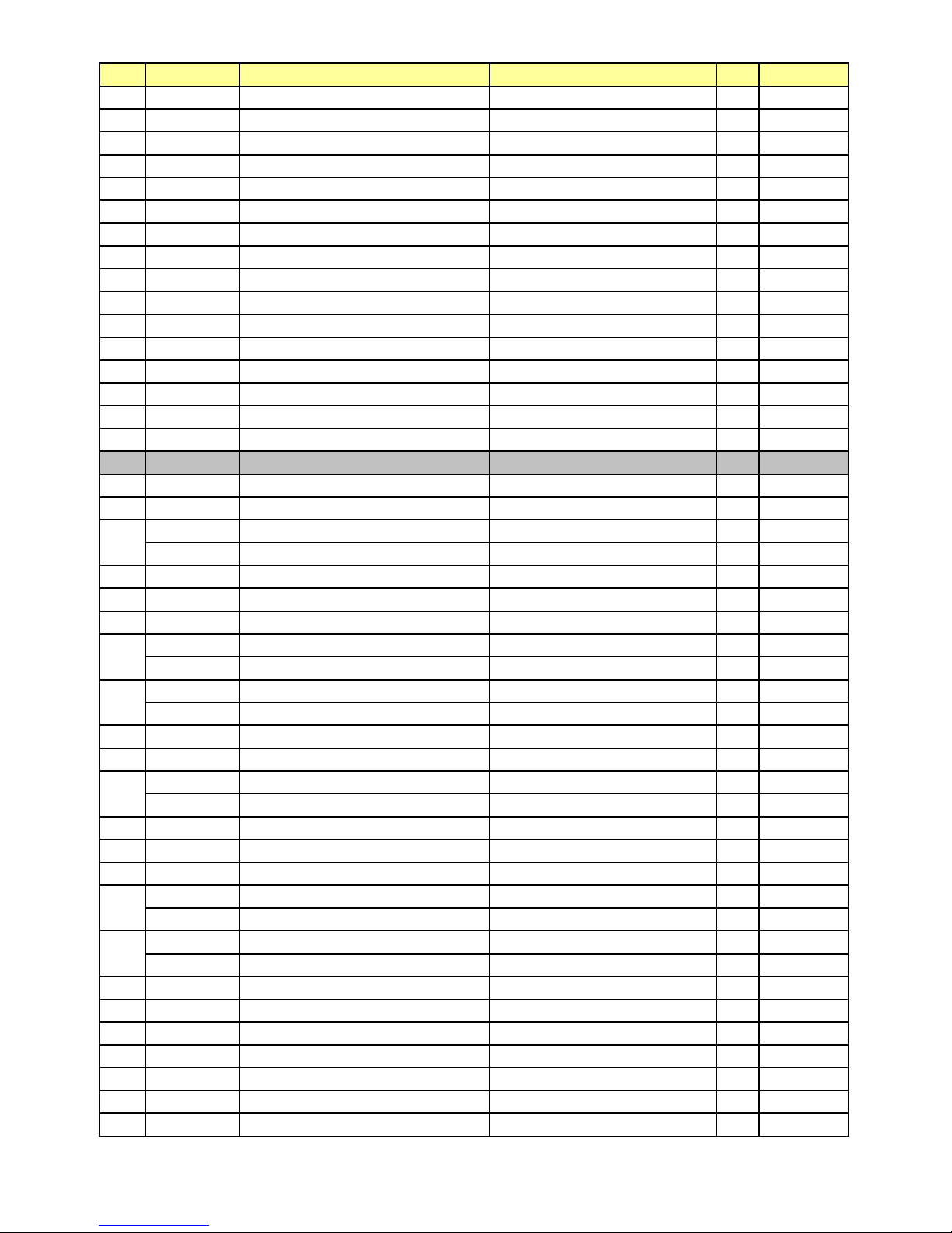
NO PART CODE PART NAME PART DESCRIPTION Q'TY REMARK
46 3011200500 CLAMP FAN SUS 304 1
47 3016806900 DRYER AS XH-9 15g 1
48 3011474710 COVER MACH ROOM AS SBHG T0.4 1
49 7112401211 SCREW TAPPING T1 TRS 4 x 12 MFZN 6
50 3012007800 FIXTURE MOTOR A PP 1
51 3015911400 MOTER R FAN AS 1
52 3012007900 FIXTURE MOTOR B HIPS 1
53 7122401211 SCREW TAPPING T2S TRS 4 x 12 MFZN 2
54 3011802200 FAN ABS (O.D.)3.17 x D110 1
55 3013344200 INSU DAMP B F-PS 1
56 3013344100 INSU DAMP A F-PS 1
57 3011471200 COVER DAMP HIPS 1
58 3018701800 DEO ANTI AS 1
59 3011471310 COVER DEO ABS 1
60 3017905300 SOCKET R LAMP AS 2
61 7121300811 SCREW TAPPING T2S PAN 3 x 8 1
62 LAMP R A 2
63 3015507900 WINDOW R LAMP A MIPS 1
64 3016002710 SPECIAL SCREW 4 x 12 2
3017827300 SHELF R A AS GLASS + HIPS 4 FRS-2041
3017831900 SHELF R A AS FRAME + SHELF + FIXTURE 4 FRS-2441
67 3012514500 GUIDE CASE A *L AS ABS 2
68 3012514600 GUIDE CASE A *R AS ABS 2
69 7142401611 SCREW TAPPING T2 TRS 4 x 16 MFZN 4
3011171200 CASE CHILD AS GPPS + HIPS 1 FRS-2041
3011177700 CASE CHILD AS CASE + FRAME STAMPING 1 FRS-2441
3011473100 COVER VEGETB CASE A GPPS 1 FRS-2041
3011485300 COVER VEGETB CASE A GPPS 1 FRS-2441
72 3018701800 DEO ANTI AS 1
73 3011472900 COVER RETURN DUCT HIPS 1
3011172000 CASE VEGETB A AS GPPS + HIPS 1 FRS-2041
3011178200 CASE VEGETB A AS CASE + FRAME STAMPING 1 FRS-2441
75 3012514700 GUIDE CASE B *L AS ABS 1
76 3012514800 GUIDE CASE B *R AS ABS 1
77 7142401611 SCREW TAPPING T2 TRS 4 x 16 MFZN 2
3011473200 COVER VEGETB CASE B GPPS 1 FRS-2041
3011485400 COVER VEGETB CASE B GPPS 1 FRS-2441
3011172100 CASE VEGETABLE B AS GPPS + HIPS 1 FRS-2041
3011178300 CASE VEGETABLE B AS CASE + FRAME STAMPING 1 FRS-2441
80 3017827500 SHELF WINE AS ABS 1
81 3016002710 SPECIAL SCREW 4 x 12 2
82 3010903200 CAP SCREW PE 2
83 3018124000 SWITCH LAMP SP201R-7DR 1
84 3017100500 FLAP MULT DUCT PP 1
85 3013345000 INSU MULT DUCT AS F-PS 1
86 3011472700 COVER MULT DUCT HIPS 1
74
78
79
66
70
71
- 73 -
Page 74
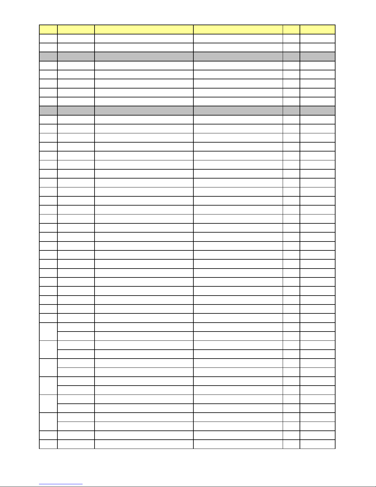
NO PART CODE PART NAME PART DESCRIPTION Q'TY REMARK
87 3013408100 KNOB MULT DUCT ABS 1
88 3017905310 SOCKET R LAMP AS 250V 1A 1
89 LAMP R B 1
90 3015508000 WINDOW R LAMP B MIPS 1
91 3011473000 COVER SENS ABS 1
92 3014805400 SENSOR R AS PBN-438 1
93 3011171300 CASE EGG AS GPPS 1
94 3012514200 GUIDE DRN GA 1
95 HEATER DRN GUIDE AS 1
96 7112401211 SCREW TAPPING T1 TRS 4 x 12 MFZN 1
97 3012007800 FIXTURE MOTOR A PP 1
98 3015911300 MOTOR F FAN AS DC12V 2.5W 1
99 3018914400 LOUVER F C PP 1
100 7142401611 SCREW TAPPING T2 TRS 4 x 16 MFZN 3
101 3011802200 FAN ABS (O.D.)3.17 x D110 1
102 3018914900 LOUVER F D AS PP 1
103 3014805300 SENSOR F AS PT-38 1
104 3018914700 LOUVER F B AS HIPS 1
105 3018914610 LOUVER F A AS HIPS 1
106 7142401611 SCREW TAPPING T2 TRS 4 x 16 MFZN 3
107 3010924600 CAP F LUVR HIPS 3
108 3011473000 COVER SENS ABS 1
109 3014559510 PLATE LAMP F SBHG T0.8 1
110 3017905200 SOCKET F LAMP AS 2
111 3013602000 LAMP F/R 240V 25W 2
112 7121300811 SCREW TAPPING T2S PAN 3X8 MFZN 4
113 7112401211 SCREW TAPPING T1 TRS 4 x 12 MFZN 4
114 3015507710 WINDOW F LAMP MIPS 1
115 3016002710 SPECIAL SCREW 4 x 12 2
117 3017827100 SHELF F A AS GLASS + HIPS 3
118 3018124000 SWITCH LAMP SP201R-7DR 1
119 3015101300 SPRING ICING CASE STS304WPB 2
3011170600 CASE ICING PP 2 FRS-2041
3011177300 CASE ICING PP 2 FRS-2441
3012203800 FRAME ICE MAKER ABS 1 FRS-2041
3012205300 FRAME ICE MAKER ABS 1 FRS-2441
3013408000 KNOB ICEING CASE HIPS 2 FRS-2041
3013409300 KNOB ICEING CASE HIPS 2 FRS-2441
3011171800 CASE ICE AS GPPS + HIPS 1 FRS-2041
3011178000 CASE ICE AS GPPS + HIPS 1 FRS-2441
3011171400 CASE F A AS GPPS + HIPS 1 FRS-2041
3011177800 CASE F A AS GPPS + HIPS 1 FRS-2441
3011171500 CASE F B AS GPPS + HIPS 1 FRS-2041
3011177900 CASE F B AS GPPS + HIPS 1 FRS-2441
126 3012516000 GUIDE F POCKET PP 2
127 3019019100 POCKET F *U HIPS 5
125
121
122
123
124
120
- 74 -
Page 75
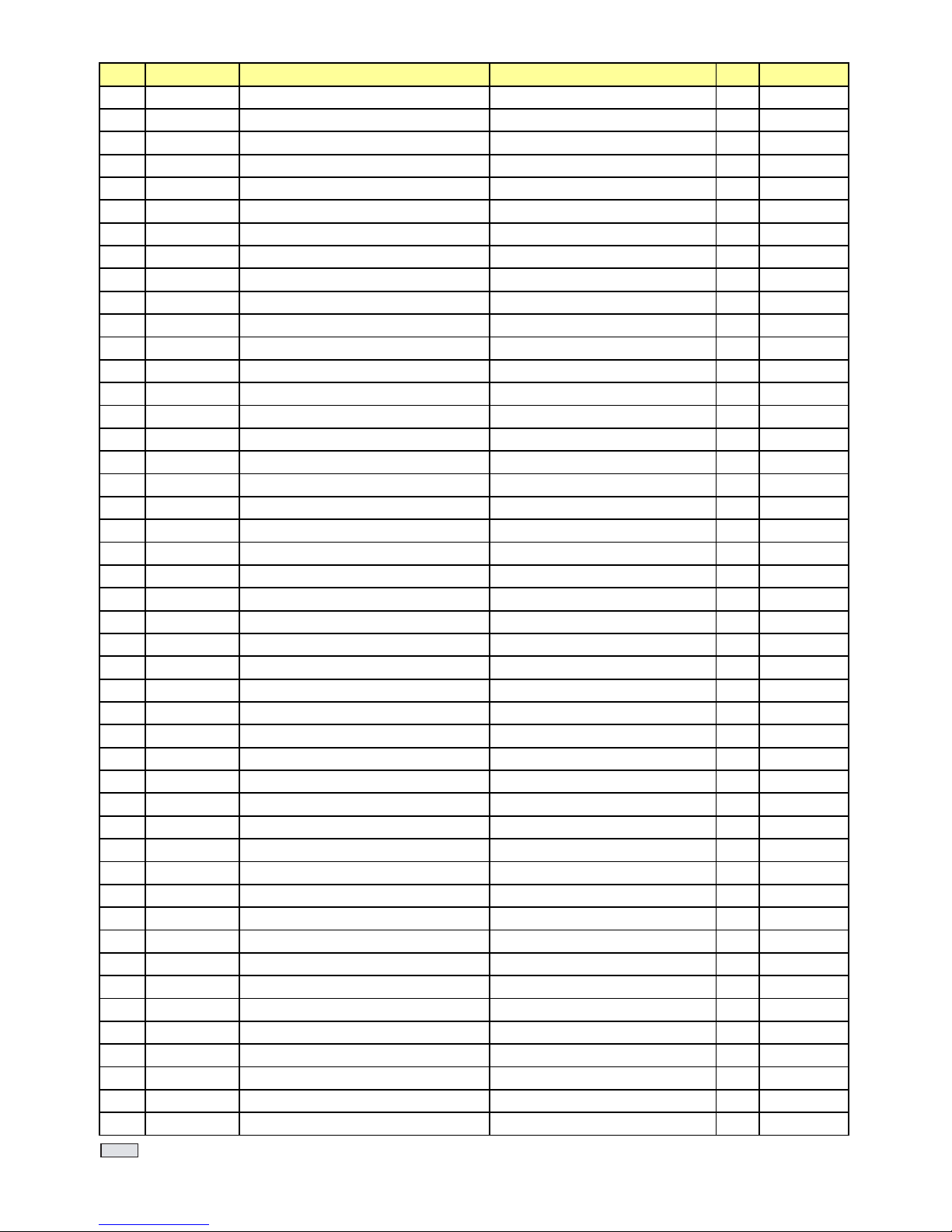
NO PART CODE PART NAME PART DESCRIPTION Q'TY REMARK
128 3019019000 POCKET F *T HIPS 1
129 3000018700 ASSY F DR FRS-2021 1
129-1 3012314200 GASKET F DR AS PVC 1
129-2 3000003700 ASSY F DR URT 1
132 3011623800 DECO HNDL *T ABS 1
133 3012628500 HANDLE AL 1
134 3011613900 DECO HNDL *U ABS 1
135 3016031700 SPECIAL SCREW 2
136 3010326100 BASE DECO COVER *T HIPS 1
137 3010326200 BASE DECO COVER *U HIPS 1
138 7112401211 SCREW TAPPING T1 TRS 4 x 12 MFZN 8
139 3011472100 COVER HNDL DECO *T ABS 1
140 3011472200 COVER HNDL DECO *U ABS 1
141 3011747510 COVER F PCB AS FRS-2021 1
141-1 7111300811 SCREW TAPPING T1 PAN 3 x 8 MFZN 7
141-2 30143B4110 PCB F AS 1
141-3 3016302600 BUTTON CONTL B ABS 2
141-4 3016303100 BUTTON CONTL A ABS 4
141-5 3015507800 WINDOW F PCB ABS 1
141-6 3011471600 COVER F PCB ABS 1
148 3019019400 POCKET DAIRY AS GPPS + HIPS 1
149 3019019300 POCKET R *S GPPS 1
150 3019019800 POCKET R *M HIPS 2
151 3011474600 COVER HOMEBAR AS GPPS 1
152 3012514100 GUIDE R POKT HIPS 2
153 3012513400 GUIDE BOTL PP 2
154 3019019200 POCKET R HIPS 2
155 3000025300 ASSY R DR FRS-2041 1
155-1 3012314500 GASKET R DR AS PVC 1
155-2 3012314400 GASKET HOMEBAR B AS PVC 1
155-3 3000003810 ASSY R DR URT 1
159 3012314300 GASKET HOMEBAR A AS PVC 1
160 3011471700 COVER FRAME HOMEBAR ABS 1
161 3012918300 HINGE HOMEBAR *R AS STS304 1
162 3012918200 HINGE HOMEBAR *L AS STS304 1
163 3016030600 SPECIAL SCREW C SUS M5 8
164 3010951600 CAP HOMEBAR ARM PLT *R ABS 1
165 3012514000 GUIDE HOMEBAR ARM RING A POM 1
166 3016030800 SPECIAL SCREW A SUS M5 2
167 3016030600 SPECIAL SCREW C SUS M5 2
168 3015202100 STOPPER HOMEBAR DR PP 2
169 3016030900 SPECIAL SCREW B SUS M5 2
170 3014560300 PLATE HOMEBAR ARM *R AS STS 304 1
171 3011791900 DOOR HOMEBAR URT AS 1
172 3010951500 CAP HOMEBAR ARM PLT *L ABS 1
173 3014560200 PLATE HOMEBAR ARM *L AS STS 304 1
- 75 -
means that you're recommended to refer to the
No. 2-2 "Eletric Parts".
 Loading...