

Daewoo FM-MECHA, FM-M Service Manual

Technical Service Guide
VCR MECHANISM UNIT
(FM-MECHA)

CONTENTS
1. DESCRIPTION OF THE MECHANISM
1. CHARACTERSTIC OF THE FM-DECK MECHANISM........................................................................................................2
2. DESCRIPTION OF THE MODE............................................................................................................................................3
3. FM DECK TIMING CHART.................................................................................................................................................12
4. WIRING DIAGRAM .............................................................................................................................................................13
2. ARRANGEMENT AND CHECK FOR THE MAJOR P AR TS
1. PARTS LOCATION............................................................................................................................................................. 15
2. PERIODIC MAINTENANCE AND SERVICE SCHEDULE .................................................................................................18
3. JIGS AND TOOLS...............................................................................................................................................................20
3. DISASSEMBLY AND EXCHANGE
1. MECHANICAL CHECKS.................................................................................................................................................... 22
2. REPLACEMENT OF THE DRUM TOTAL ASS'Y...............................................................................................................23
3. REPLACEMENT OF THE S, T SLANT POLE ASS'Y.........................................................................................................24
4. REPLACEMENT OF THE PINCH LEVER TOTAL ASS'Y..................................................................................................25
5. REPLACEMENT OF THE A/C HEAD TOTAL ASS'Y.........................................................................................................25
6. REPLACEMENT OF THE L/C BRKT ASS'Y......................................................................................................................26
7. REPLACEMENT OF THE MAIN PLATE.............................................................................................................................27
8. REPLACEMENT OF THE CAM GEAR, RELAY PLATE, F/L RACK..................................................................................28
9. REPLACEMENT OF THE TENSION LEVER ASS'Y..........................................................................................................29
10. REPLACEMENT OF THE CAPSTAN MOTOR................................................................................................................30
4. MECHANICAL ADJUSTMENT
1. CHECK FOR THE MECHANICAL POSITION....................................................................................................................31
2. HOW TO SET MECHANICAL MODE.................................................................................................................................34
3. MEASUREMENT OF PRESSING FORCE FOR PINCH ROLLER....................................................................................34
4. ADJUSTMENT OF TENSION POLE POSITION................................................................................................................35
5. MEASUREMENT OF THE BACK TENTION......................................................................................................................35
5. THE ADJUSTMENT OF THE T APE TRANSPOR TING SYSTEM
1. THE SCHEMATIC DIAGRAM OF TAPE TRANSPORTING SYSTEM ..............................................................................36
2. ADJUSTMENT FLOW.........................................................................................................................................................37
3. ADJUSTMENT PROCEDURES..........................................................................................................................................38
6. EXPLODED VIEW & P AR TS LIST
1. EXPLODED VIEW OF DECK ASS'Y ..................................................................................................................................45
2. PARTS LIST OF DECK ASS'Y ...........................................................................................................................................46
3. EXPLODED VIEW OF F/L ASS'Y.................................................................................................. .....................................48
4. PARTS LIST OF F/L ASS'Y................................................................................................................................................ 49
5. MAIN SPARE PARTS LIST OF DECK ASS'Y......................................................................................... ...........................50
SERVICE NOTICE...................................................................................................................................................................52
1

1. DESCRIPTION OF THE MECHANISM
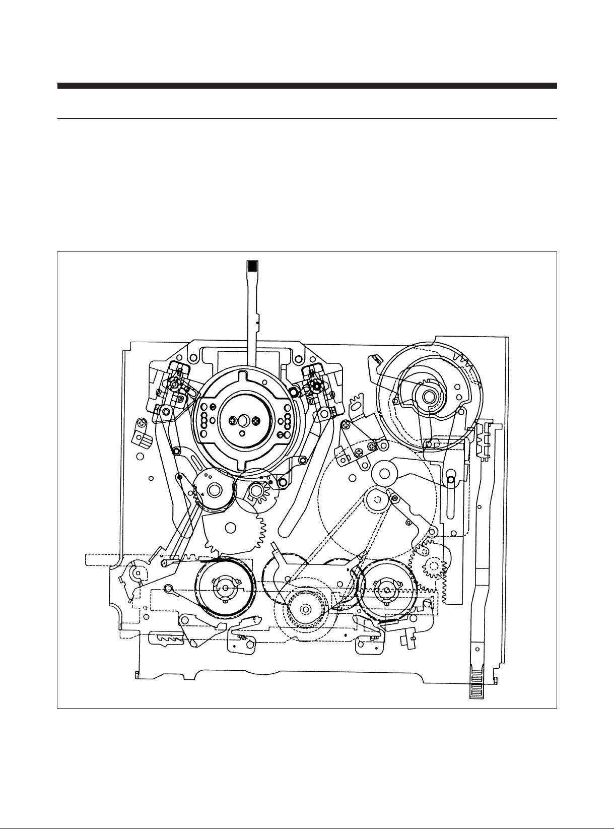
1. CHARACTERISTIC OF THE FM-DECK MECHANISM
1) FM-MECHA DECK follows the VHS standard and PAL standard.
2) FM-MECHA DECK has 3 motors (DRUM MOTOR, CAPSTAN MOTOR and L/C MOTOR).
3) FM-MECHA DECK uses L/C MOTOR to drive FRONT LOADING.
4) FM-MECHA DECK has 7 MODES (EJECT/INITIAL/IDLE/REV/SLOW/PLAY/FF & REW) and each mode is composed of
4 bit mode Signals and realized by the mode switch which is driven by the L/C MOTOR.
5) FM-MECHA uses the FULL LOADING system in which mode shifting time (especially, picture appearing time) is short.
6) FM-MECHA DECK is removed the DECK PCB and connected to MAIN PCB by using the B to B TYPE CONNECTOR.
2
2. DESCRIPTION OF THE MODE
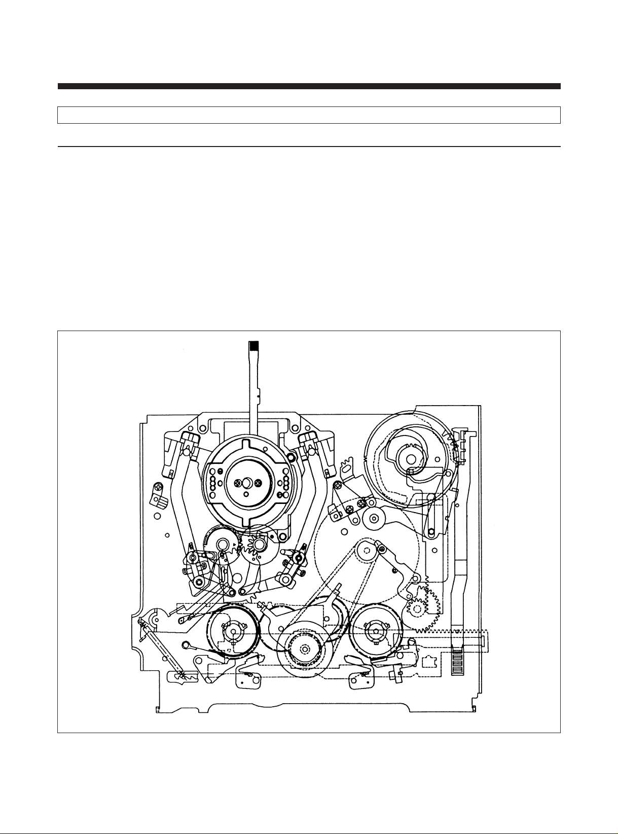
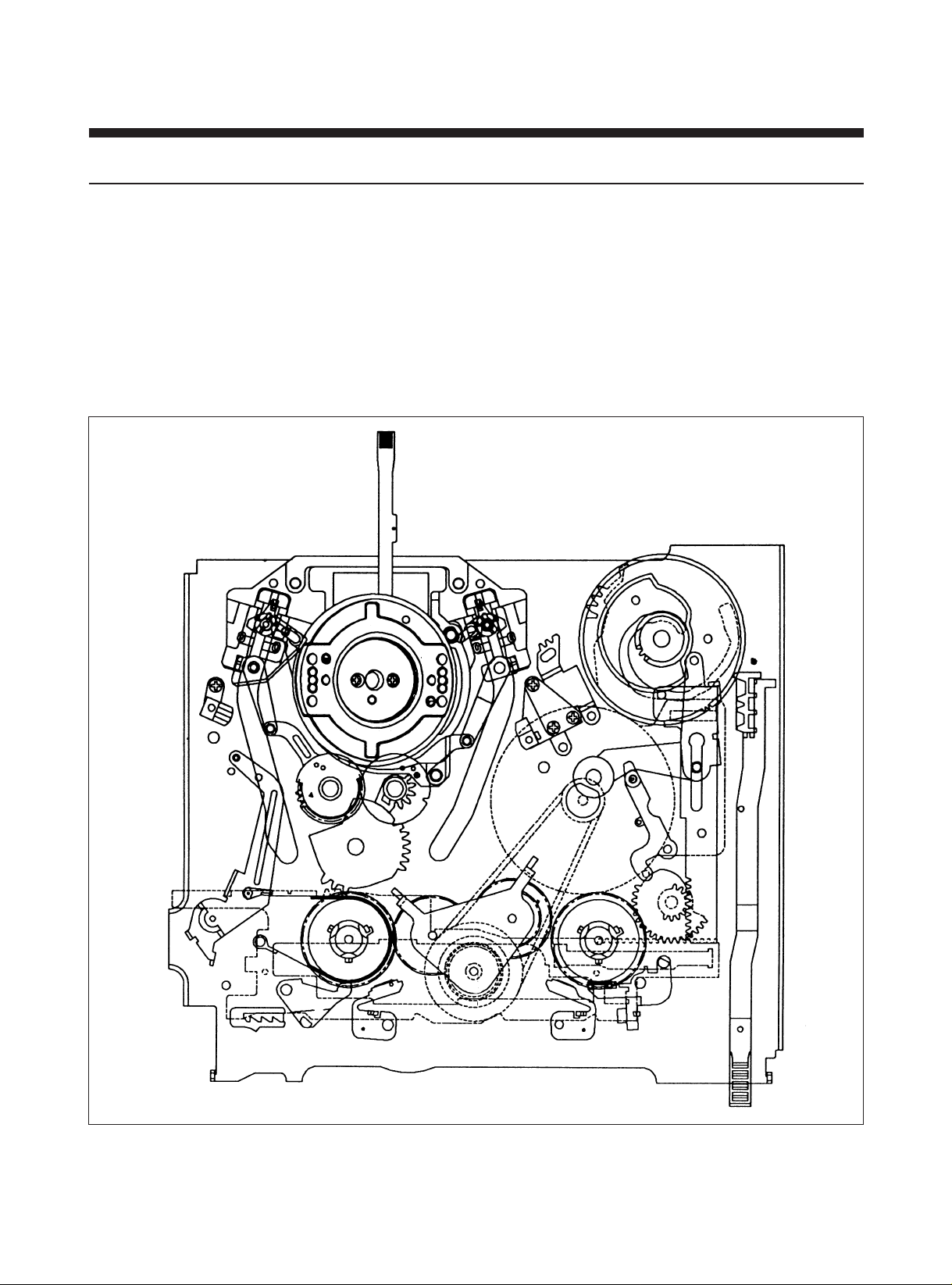
1) EJECT MODE
A. In this mode, the cassette In/Out operation is performed by the CW/CCW rotation of the L/C motor to which the Front
Loading driving parts are directly related.
• CASSETTE IN : If the cassette is inserted into the entrance with proper insertion force, Mode Switch is rotated by
insertion force and break from Eject mode.
At the same time the Cassette In is detected. And instantely the cassette loading is performed and
the L/C motor proceeds to the PLAY/STOP mode.
• CASSETTE OUT: In this state the Cassette Holder is located at the enterance of the front panel, and only the Cassette
In operation can be excuted.
B. Mechanical Arrangement
a. The BAND BRAKE is released from the S REEL TABLE.
b. The S & T MAIN BRAKE is released from the S & T REEL TABLE.
c. The S & T SUB BRAKE is released from the S & T REEL TABLE.
d. The IDLER GEAR is separated from the S & T REEL TABLE.
EJECT MODE
3
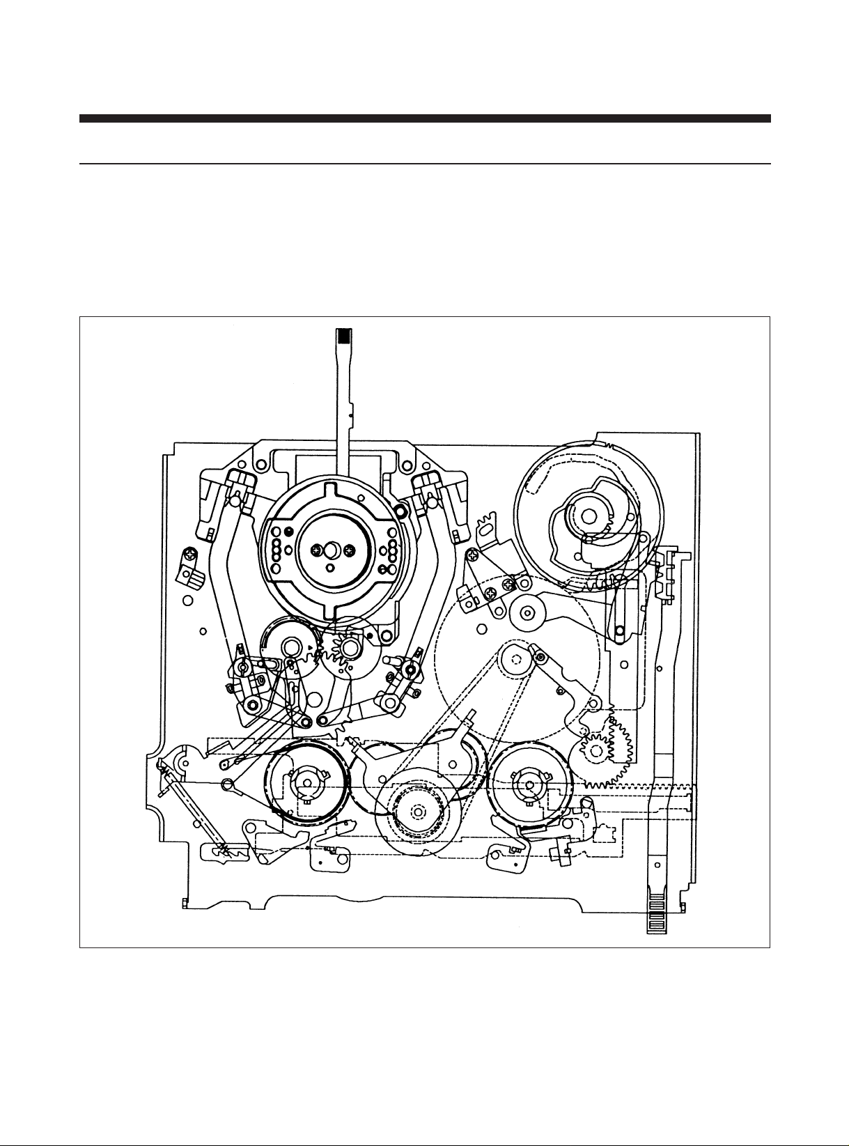
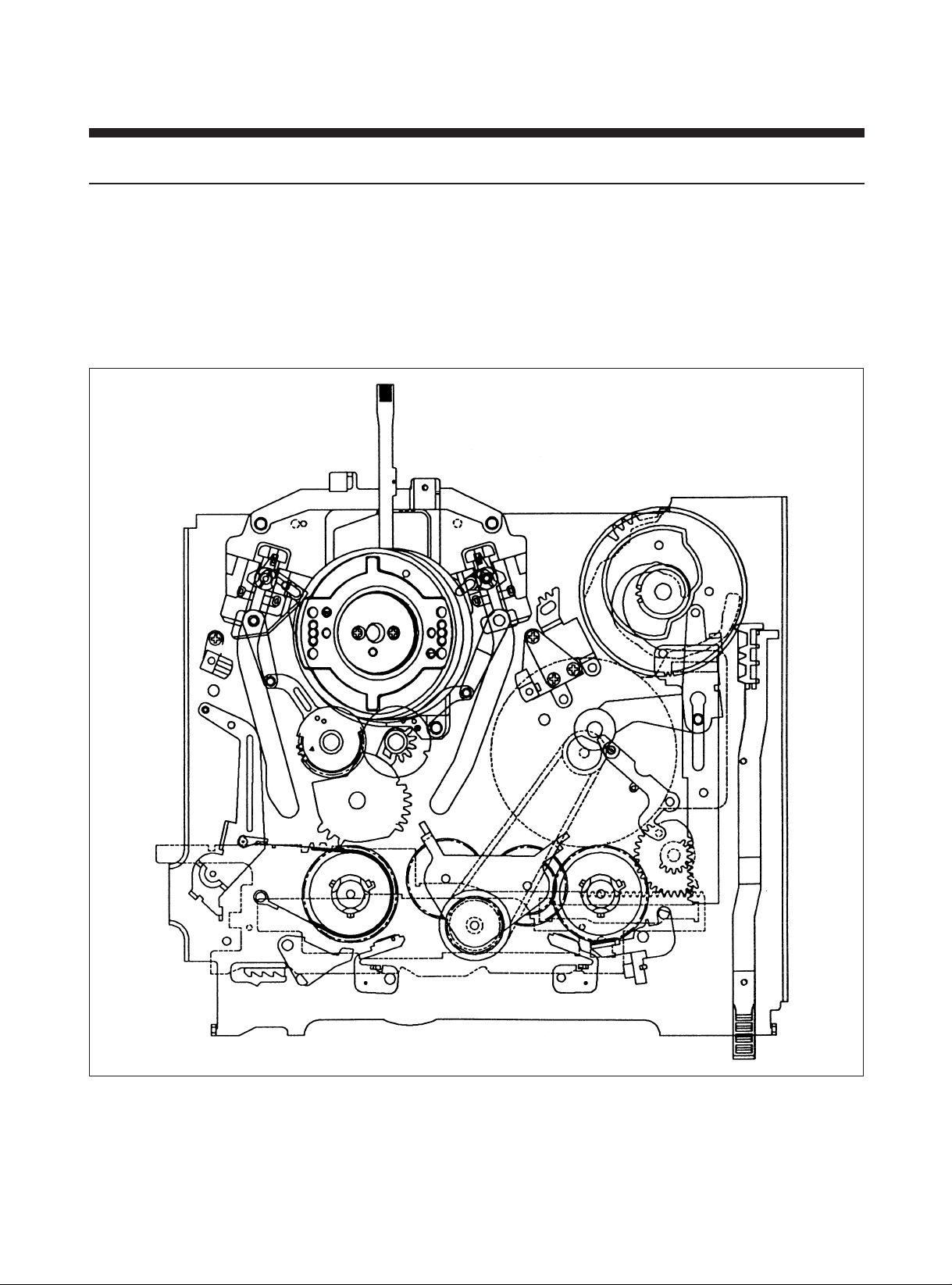
2) INITIAL MODE
A. This mode is used as a reference mode for unloading location when power is off.
B. Mechanical Arrangement
a. The BAND BRAKE is released from the S REEL TABLE.
b. The S MAIN BRAKE is released from the S REEL TABLE.
c. The T MAIN BRAKE is applied to the T REEL TABLE.
d. The S & T BRAKE is released from the S & T REEL TABLE.
INITIAL MODE
4
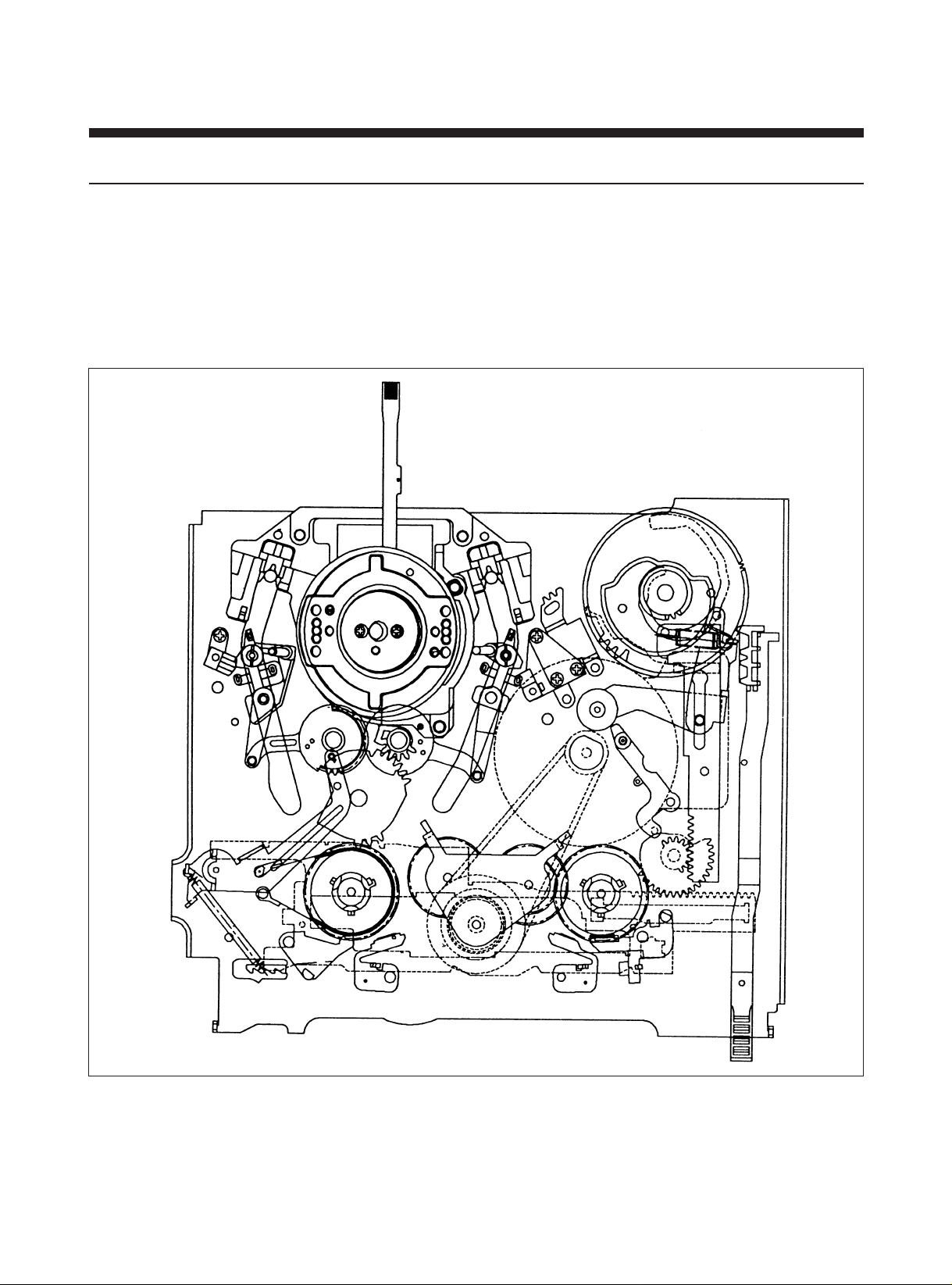
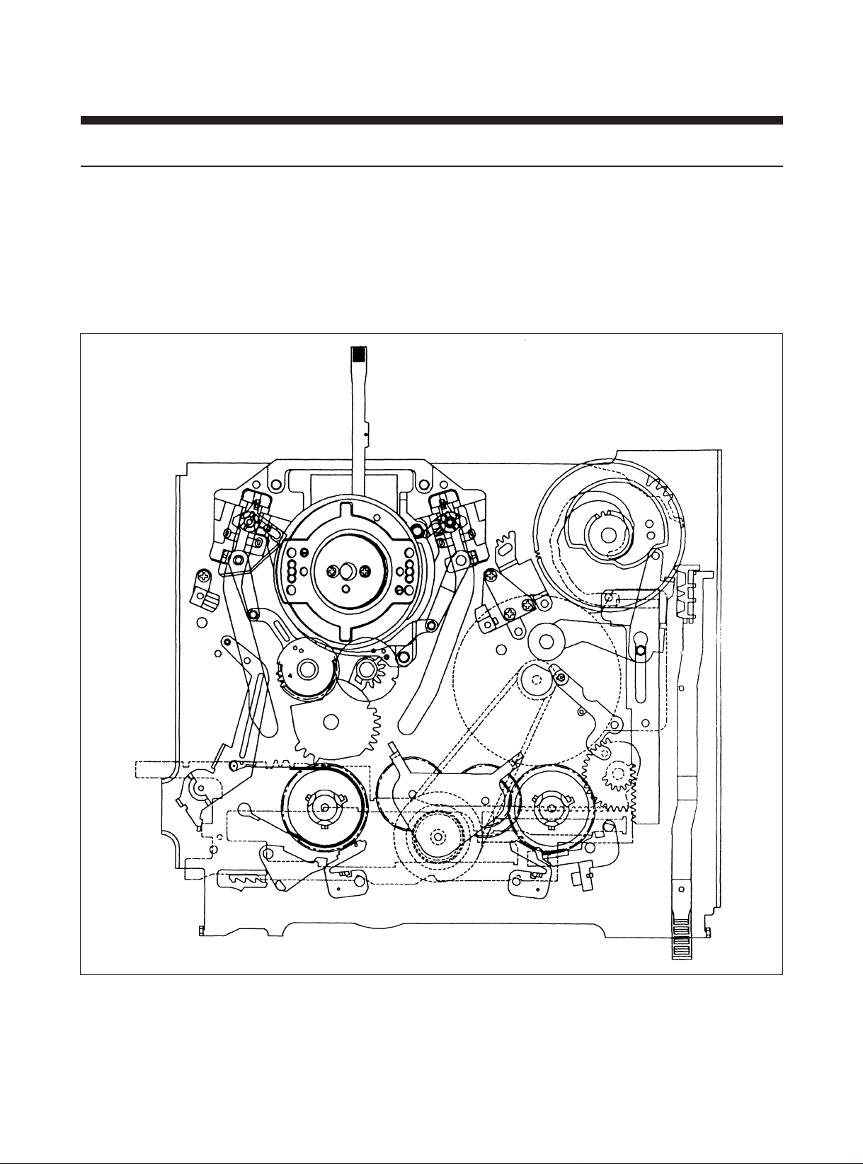
3) LOADING SECTION
A. LOADING SECTION is used to lead a tape to either transporting situation or initial situation by forwarding and
backwarding of POLE BASE AS.
B. Mechanical Arrangement
a. The BAND BRAKE is released from the S REEL TABLE.
b. The S & T MAIN BRAKE is released from the S & T REEL TABLE.
c. The S & T SUB BRAKE is applied to the S & T REEL TABLE.
d. The IDLE GEAR is separated from the S & T REEL TABLE.
LOADING MODE
5
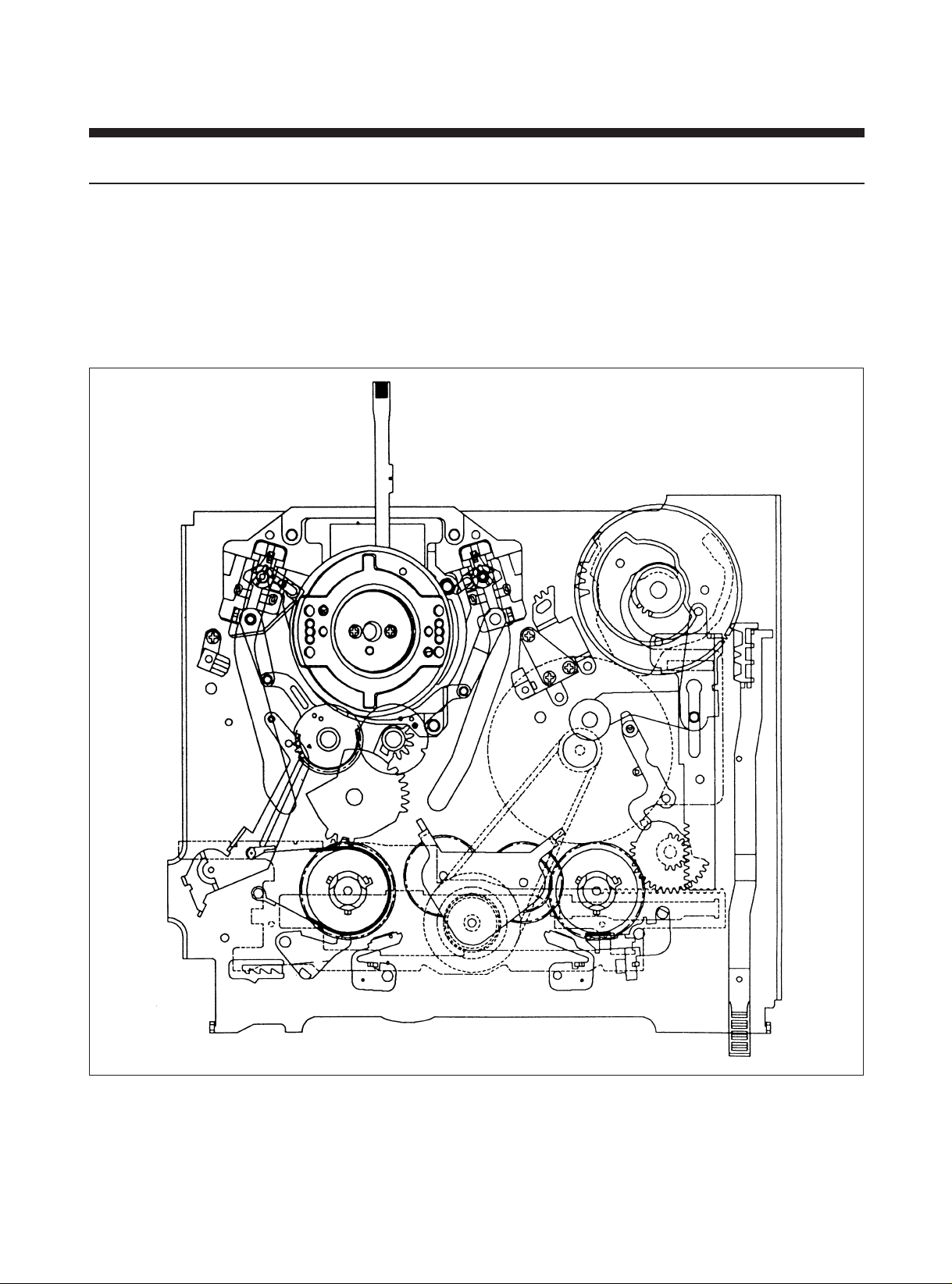
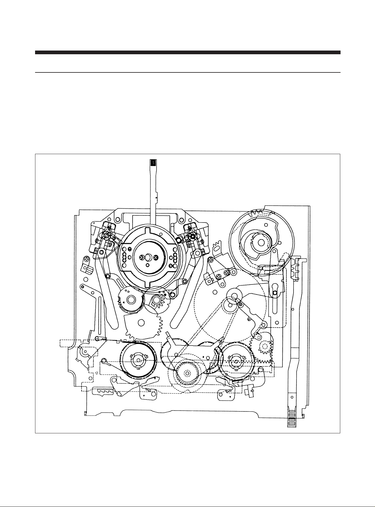
4) IDLE MODE
A. Idle mode is used to reduce the tape tension and load in drum and posts which are used for tape transportation by
seperating PINCH ROLLER from CAPSTAN SHAFT when DECK is performed from forward tape running to backward
tape running or from backward tape running to forward tape running.
B. Mechanical Arrangement
a. The S & T MAIN BRAKE is released from the S & T REEL TABLE.
b. The S & T SUB BRAKE is applied to the S & T REEL TABLE.
C. The PINCH ROLLER is separated from the CAPSTAN SHAFT.
IDLE MODE
6
5) REVIEW MODE
A. The Review Search operation is performed in this mode. This mode is obtained by pressing the REW button in the state
of playing. The L/C motor rotated until the Cam switch detects the REVIEW mode. When the Cam switch detects the
REVIEW mode, the L/C motor is stopped and at the nearly time the Capstan starts to rotate CCW to transport the tape
reversely.
B. Mechanical Arrangement
a. The BAND BRAKE is released from the S REEL TABLE.
b. The S & T MAIN BRAKE are released from the S & T REEL TABLE.
c. The S SUB BRAKE is applied to the S REEL TABLE.
d. The PINCH ROLLER is applied to the CAPSTAN SHAFT to transport the tape reversely.
e. The REVIEW ARM is moved forward to perform the role of the tape transporting POST.
REVIEW MODE
7
6) SLOW MODE
A. This mode is performed the forward and backward slow searching.
B. Mechanical Arrangement
a. The BAND BRAKE is applied to the S REEL TABLE.
b. The S & T MAIN BRAKE is released from the S & T REEL BRAKE.
c. The S & T SUB BRAKE is released from the S & T REEL TABLE.
d. The REVIEW ARM is located at the initial position.
e. The CAPSTAN BRAKE is applied to the CAPSTAN MOTOR.
F/R SLOW MODE
8
7) PLAY/RECORD/STOP MODE
A. The PLAY/RECORD/STOP mode transport the tape from the S REEL TABLE to the T REEL TABLE in the regular speed
to perform the recording and playback. Also this mode is to STAND-BY the next operation of key-in.
B. Mechanical Arrangement
a. The TENTION POLE is located at the appointed position.
b. The BAND BRAKE is applied to the S REEL TABLE for excute the tape tension servo.
c. The S & T MAIN BRAKE ans S & T SUB BRAKE is released from the S & T REEL TABLE.
d. The PINCH ROLLER is applied to the CAPSTAN MOTOR.
PLAY MODE
9
8) BRAKE MODE
A. This mode is a mechanical mode which lies in between PLAY mode and FF/REW mode.
If EJECT, STOP or PLAY button is pressed in the FF/REW mode, S & T MAIN BRAKES are applied to the S & T REEL
TABLE quickly. So, It can be prevented to loosen of the tape.
B. Mechanical Arrangement
a. The BAND BRAKE is released from the S REEL TABLE.
b. The S & T MAIN BRAKE are applied to the S & T REEL TABLE.
c. The S & T SUB BRAKE are released from the S & T REEL TABLE.
d. The PINCH ROLLER is released from the CAPSTAN SHAFT.
BRAKE MODE
10
9) FF/REW MODE
A. In this mode, the cassette tape is rewound to the S & T REEL Table at the high speed by the CW/CCW rotation of the
Capstan Motor which is directly releated to the S & T REEL Table.
If the START/END SENSOR is on during this operation, it returns to the STOP MODE and excutes CUE/REV.
During the FF/REW operation, the Drum continues to rotate with the tape wrapped around it and the tape is contacted
to the CONTROL HEAD that reads the VISS signal.
B. Mechanical Arrangement
a. The BAND BRAKE and the S & T MAIN BRAKE are released from the S & T REEL TABLE.
b. The PINCH ROLLER is separated from the CAPSTAN SHAFT.
FF/REW MODE
11
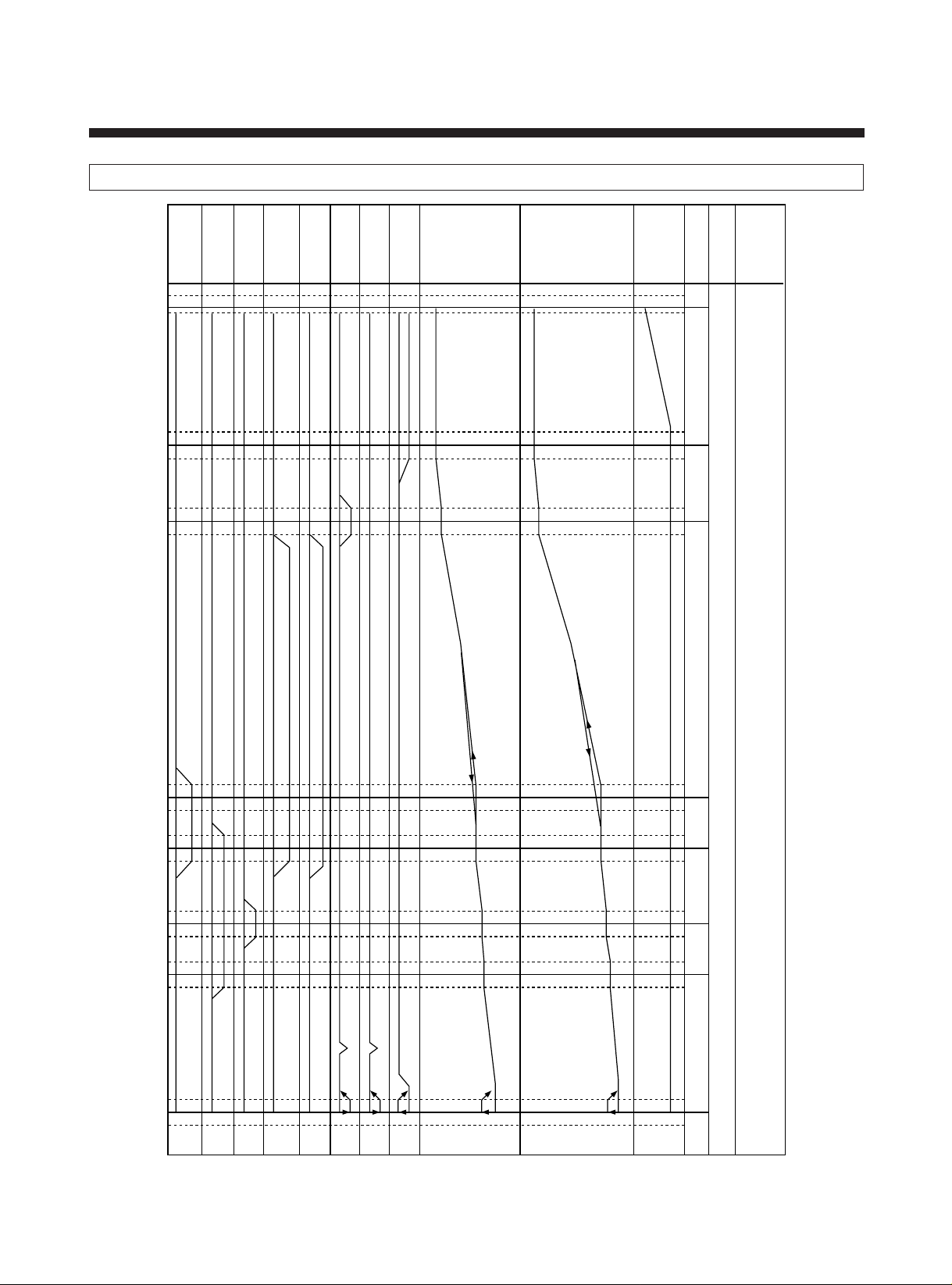
3. FM DECK TIMING CHART
. . . . . . . . . . . . . . . . . . . . . . .
. . . . . . . . . . . . . . . . . . . . . . . .
. . . . .
. . . . . .
. . . . . . . . . . . . . . . . . . . . . . . . . . . . . . . . . . . . . . . . . . . . . . . .
. . . . . . . . . . . . . . . . . . . . . . . . . . . . . . . . . . . . . . . . . . . . . . . . .
. . . . . . . . . . . . . . . . . . . . . . . . . . . . . . . . . . . . . . . . . . . . . . . . . .
. . . . . . . . . . . . . . . . . . . . . . . . . . . . . . . . . . . . . . . . . . . . . . . .
. . . . . . . . . . . . . . . . . . . . . . . . . . . . . . . . . . . . . . . . . . . . . . . . .
. . . . . . . . . . . . . . . . . . . . . . . . . . . . . . . . . . . . . . . . . . . . . . . . . .
. . . . .
. . . . . .
. . . . . . . . . . . . . . . . . . . . . . .
. . . . . . . . . . . . . . . . . . . . . . . .
. . . . . . . . . . . . . . . . . . . . . . . . .
. . . . . . . . . . . .
. . . . . . . . . . . . .
. . . . . . . . . . . . . .
MODE
MODE
CAM ANGLE
F/L RACK
RELAY CAM
MAIN PLATE
REEL
DRIVE
S MAIN
BRAKE
T MAIN
BRAKE
S SUB
BRAKE
T SUB
BRAKE
CAP. BRAKE
PINCH
REV ARM
L
L
L
L
L
L
L
0
DIRECT
8
34.1
9.7
3.97
SLIP
5.6
13.3
10.4
13.7
18.25
19.9
22.5
23.6
23.92
27.77
33.83
36.4
26.6
25.3
43.4
40.37
–5
2
70
80
100
110
210
220
230
240
260
270
280
290
335
345
340
285
265
235
215
105
75
0
EJECT
INITIAL
(LOADING)
IDLE
REV
SLOW
PLAY
/STOP
FF/REW
(BRAKE)
12
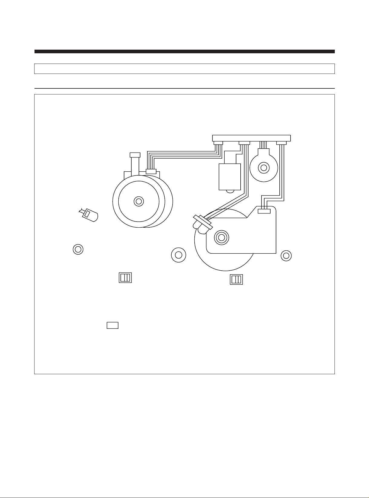
DRUM MOTOR
CN-A
CN-C1 CN-C2
CAM SW
L/C MOTOR
ACE HEAD
CAPSTAN MOTOR
START SENSOR
(MAIN PCB)
REEL SENSOR
(MAIN PCB)
LED (MAIN PCB)
REEL SENSOR
(MAIN PCB)
SWITCH DETECTOR
(MAIN PCB)
END SENSOR
(MAIN PCB)
FE HEAD
CN-B
4. WIRING DIAGRAM
1) WIRE DIAGRAM
13

2) CONNECTOR PIN ARRANGEMENT
CN-A (2 HEAD MONO: ELCO) CN-C1 (TAICO) CN-2 (TAICO)
1 VR 1
2 COMMON
3 VL 1
4 GND
CN B (JAE)
1 FE HEAD
2 GND
1 DRUM FG
2 DRUM M/T GND
3 DRUM PG
4 DRUM SPP CTL
5 DRUM M/T 12V
6 CAM A
7 CAM B
8 CAM C
9 CAM D
10 LM (+)
11 LM (—)
12 A/E HEAD
13 AUDIO GND
14 AUDIO HEAD
15 AUDIO HEAD
16 CTL HEAD (—)
17 CTL HEAD (+)
18 CAP CTL REF
1 CAPSTAN I LM.
2 CONTROL
3 CAP IC GND
4 CAP M/T GND
5 CAPSTAN F/R
6 CAPSTAN FG
7 EVER 5V
8 CAP M/T 12V
14
2. ARRANGEMENT AND CHECK FOR
THE MAJOR PAR TS
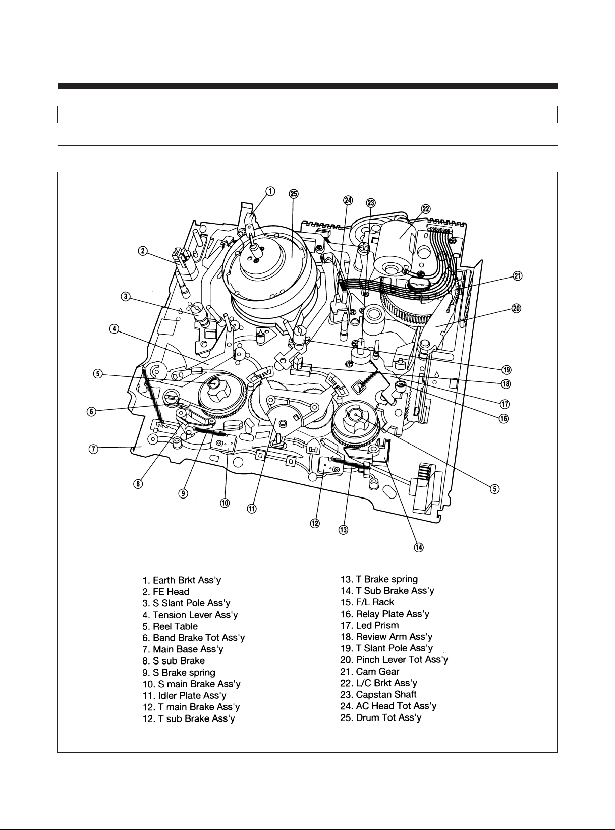
1. P AR TS LOCATION
1) PARTS LOCATION OF DECK ASS?Y
A. TOP VIEW
15
 Loading...