

Page 1

S/M NO. :
Service Manual
LED TV
CHASSIS :
SE-V26XB
Model : EX236E2BCFA
Caution : In this Manual, some parts can be changed for improving. their
performance without notice in the parts list. So, if you need the latest parts
information, please refer to PPL(Parts Price List)in Service Information Center.
Page 2

Contents
Safety Precaution ................... 3
Preliminary Troubleshooting .............................................................................................................................. 4
LT908D(South America) Specification ....................................... 5
LT716B-1 (South America) Specification ...................................................................................................... 12
Product Specification ...................... 19
Service Remote Controller ............................ 21
Block Diagram ................ 22
LT908X Trouble shooting ................................................................................................................................ 23
LT716X Trouble shooting ................................................................................................................................ 31
Schematic ............. 40
Software Upgrade Method .......................................................................................................................... 57
Service part list .................. 63
Mechanical Exploded View .............................. 65
Page 3

1. Safety Precaution
When moving or laying down a LCD Set, at least two people must work together. Avoid any impact
towards the LCD Set.
Do not leave a broken LCD Set on for a long time. To prevent any further damages, after checking the
condition of the broken Set, make sure to turn the power (AC) off.
When opening the BACK COVER, you must turn off power (AC) to prevent any electric shock.
When loosening screws, check the position and type of the screw. Sort out the screws and store them
separately for reassembling. Because screws holding PCBs are working as electric circuit grounding, make
sure to check if any screw is missing when assembling / reassembling. Do not leave any screws inside
the set.
A LCD Set contains different kinds of connector cables. When connecting or disconnecting cables, check
the direction and position of the cable beforehand.
Connect/disconnect the connectors slowly with care especially FFC (film) cables and FPC cables. Do not
connect or disconnect connectors instantaneously with force, and handle them carefully for reassembling.
Connectors are designed so that if the number of pins or the direction does not match, connectors will
not fit. When having problem in plugging the connectors, check their kind, position, and direction.
Page 4

2. Preliminary Troubleshooting
LCD TV does not response or remote controller does not work.
Check the power cord to be plugged.
Check the battery of the remote controller.
Sound is discontinuous or broken sometimes.
Check if [SOUND] -> [Bass] is Min or Max.
Set the [SOUND] -> [Treble] is Min or Max.
Picture of analog program is noisy.
Check the RF cable connection.
Check if [Picture] -> [N.R] is ON.
Change the [Channel] -> [Fine Tune] value.
Sound is not generated in HDMI mode.
Reconnect HDMI jack.
DVI signal has no sound. Check the output signal of device to be connected to LCD TV.
If you want to use DVI-HDMI cable, you should also connect audio cable into the LCD TV.
In spite of 'Auto Setup', picture size is not completely adapted to the screen in PC mode.
Check if the input signal is available.
Ensure that the desktop has no black area.
Some errors (picture position problem) will be occurred according to certain video card. In this case,
you should adjust 'Phase', 'Clock', 'H.Position', 'V.Position' control.
In spite of 'Auto Setup', picture is not clear in the PC mode.
Adjust 'Phase' control.
Page 5
3. SPECIFICATION
1) GENERAL DESCRIPTION
The board is a multi-purpose LCD/LED TV control board which can support LCD/LED panel
with dual/single LVDS interface. It supports resolution up to 1920x1080.
The board supports CC, Vchip, MTS, Component, HDMI, PC-RGB, CVBS, S-Video and analog
TV. It includes an audio power amplifier which can support 2X3W (4Ohm) output.
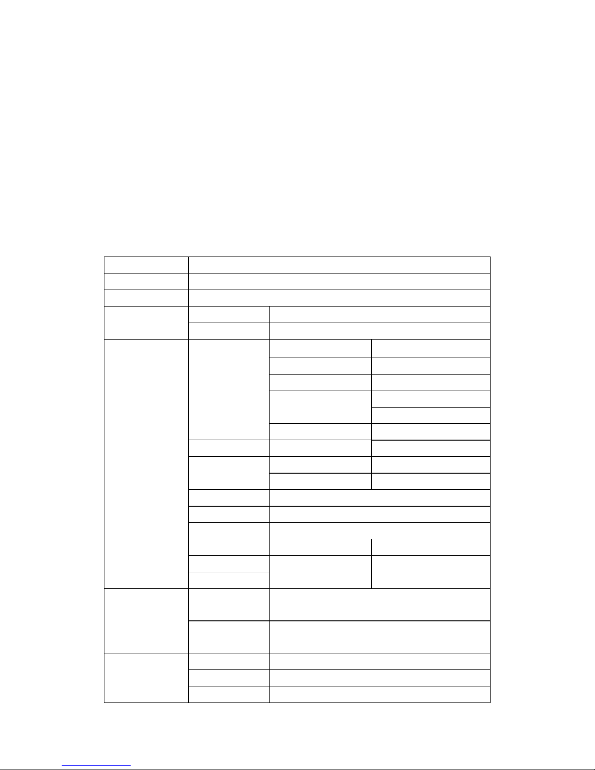
2) FEATUERS
Chipset
TSUMV26KE-LF
Market Area
South America
OSD Language
English, French, Spanish, Portuguese
Panel
Interface dual/single LVDS
Resolution Up To 1920x1080
Video Input
TV Tuner Receiving Range 55.25MHz-801.25MHz
Input Impedance 75fi
Video System PAL/NTSC
Sound System M/N
MTS
Max. storage Channels 181CH
PC-RGB Format Up to 1920x1080@60Hz
CVBS Video System PAL/NTSC
Video Level 1.0 Vp-p ±5%
S-Video S-Y:0.714Vp-p±5% S-C:0.286Vp-p±5%
HDMI 480i, 480p, 576i, 576p, 720p, 1080i, 1080p
Component 480i, 480p, 576i, 576p, 720p, 1080i, 1080p
Audio Input
PC-RGB Earphone Input 0.2 - 2.0 Vrms
CVBS L/R RCA Input 0.2 - 2.0 Vrms
Component
Audio Output
Frequency
Response
120Hz - 14000Hz @±3dB (1KHz 0dB reference
signal)
Max Output
Power
2x2.5W(4Ohm) THD+N<10%@1KHz
Power
Requirement DC +12V Power Supply
To Panel 3.3V(Max 700mA), 5V, 12V
Management Low power consumption mode,
Page 6

standby < 0.6W
ome Filter
2D
einterlace
2D
Weak signal
enhancement
YES
Noise reduction
YES
Page 7
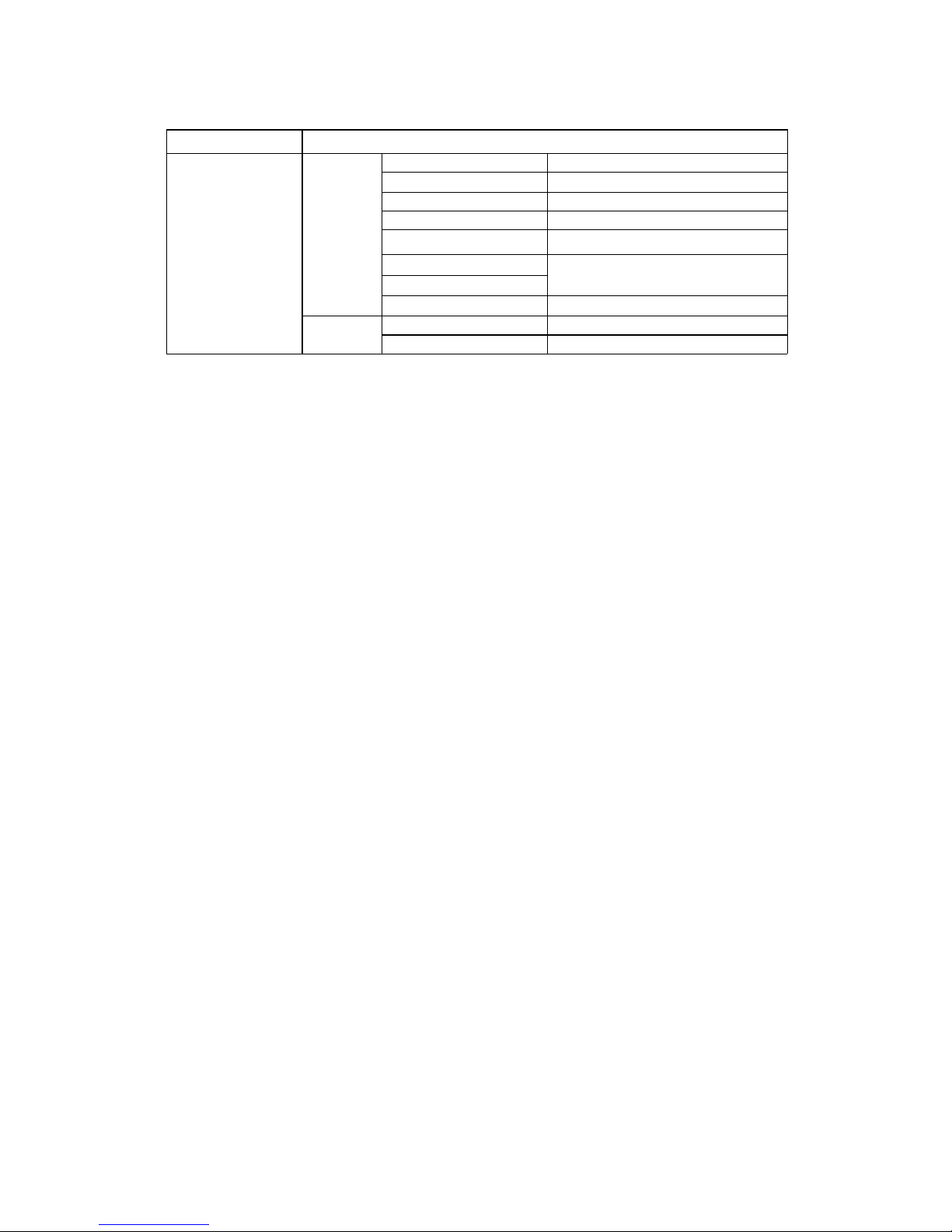
Key Function
MENU, CH+, CH-, VOL+, VOL-, INPUT, POWER
Terminlas Input
TV 1 F-Connector 75ft
HDMI 1 HDMI terminal
PC-RGB 1 D-SUB 15Pin terminal
CVBS 1 RCA terminal
Component 3 RCA terminals
CVBS Audio
2 RCA terminals
Component Audio
PC-RGB Audio 1 Earphone terminal
Output
Earphone 1 Earphone terminal
CVBS & Audio Out 3 RCA terminals(CVBS, R,L)
Page 8
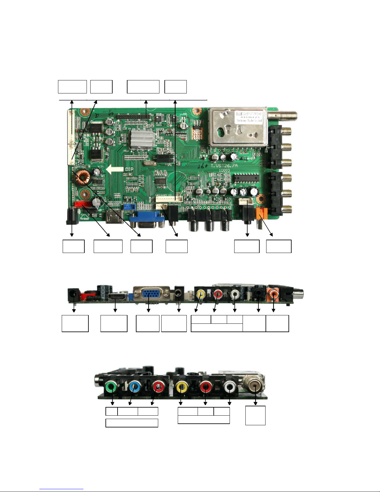
4) FUNCTION LAYOUT
TOP VIEW
FRONT VIEW
SIDE VIEW OF T.VST26.7X
CN19 :
Key
CN14 :
NC
CN17 : LVDS
Interface
CN15 :
NC
CN24 :
NC
CN3 :
Inverter
CN2 :
NC
CN26 :
NC
CN20 :
Speake
r
Coaxial :
NC
DC Power HDMI In
PC-RGB
In
PC Audio
In
CVBS
Monitor Output
R
L
Ear-
phone
Coaxial
NC
Y
Component
In
Pb/Cb CVBS
AV In
R L Pr
/Cr
RF
In
Page 9
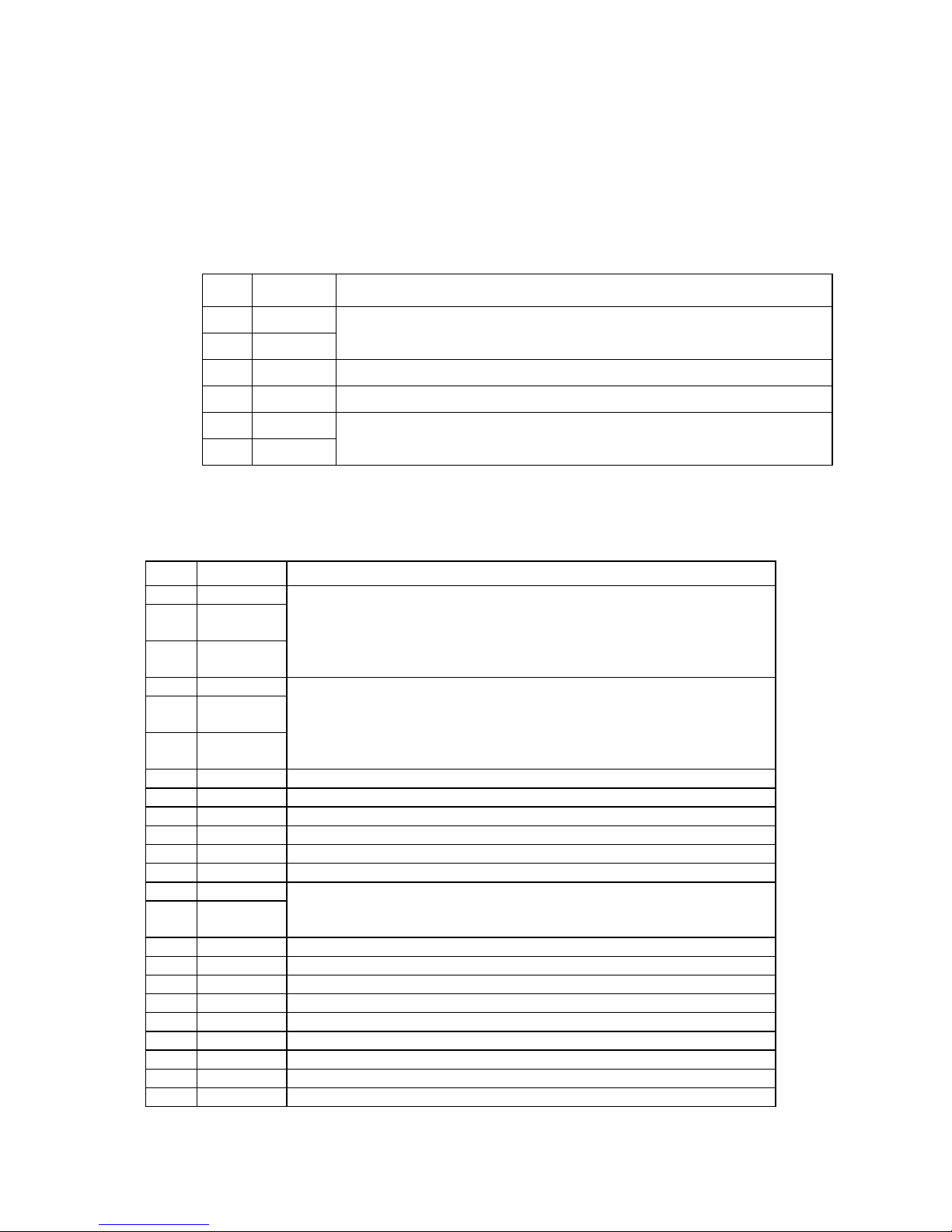
5) Connector Specification
♦ CN3(6PIN/2.0): INVERTER CONNECTOR
NO. SYMBOL DESCRIPTION
1 12V + 12V DC Power Supply
2 12V
3 BLO Back-Light ON/OFF Control for Panel
4 ADJ Brightness Adjustment for Panel
5 GND Ground
6 GND
♦ CN17(2x15PIN/2.0): LVDS INTERFACE
NO. SYMBOL DESCRIPTION
1 VSEL Power Supply for Panel
2 VSEL
3 VSEL
4 GND Ground
5 GND
6 GND
7 RXO0- LVDS ODD 0- Signal
8 RXO0+ LVDS ODD 0+ Signal
9 RXO1- LVDS ODD 1- Signal
10 RXO1 + LVDS ODD 1+ Signal
11 RXO2- LVDS ODD 2- Signal
12 RXO2+ LVDS ODD 2+ Signal
13 GND Ground
14 GND
15 RXOC- LVDS ODD Clock- Signal
16 RXOC+ LVDS ODD Clock+ Signal
17 RXO3- LVDS ODD 3- Signal
18 RXO3+ LVDS ODD 3+ Signal
19 RXE0- LVDS EVEN 0- Signal
20 RXE0+ LVDS EVEN 0+ Signal
21 RXE1- LVDS EVEN 1- Signal
22 RXE1 + LVDS EVEN 1+ Signal
23 RXE2- LVDS EVEN 2- Signal
Page 10
24 RXE2+ LVDS EVEN 2+ Signal
25/26 GND Ground
27 RXEC- LVDS EVEN Clock- Signal
28 RXEC+ LVDS EVEN Clock+ Signal
29 RXE3- LVDS EVEN 3- Signal
30 RXE3+ LVDS EVEN 3+ Signal
♦ CN19(14PIN/2.0): KEY & IR BOARD CONNECTOR
NO. SYMBOL DESCRIPTION
1 5V + 5V DC Power Supply
2 RED Red Indicator
3 GRN Green Indicator
4 IR IR Receiver
5 GND Ground
6 K0 K0
7 K1 K1
8 K2 K2
9 K3 K3
10 K4 K4
11 K5 K5
12 K6 Power (Only for power function.)
13 K7 K7
14 GND Ground
♦ CN20(4PIN/2.54): SPEAKER CONNECTOR
NO.
B
OL DESCRIPTION
1 LO Audio Left Channel Output
2 GND Ground
3 GND
4 RO Audio Right Channel Output
Page 11

4. Product Specification
Available Input Signal
i) TV Mode
Color Standard : NTCS, PAL-M/N
Reception Channel : Ch 2-13 (VHF), Ch 14-69 (UHF), Ch 1, 14~125(Cable)
Sound Transmission System : FM Mono, 2 Carrier
IF & Subcarrier:
Page 12

PIF : 45.75MHz
SIF : 41.25MHz
Sound Subcarrier: 4.5MHz, 4.72 MHz
Color Subcarrier: 3.58MHz
ii) Multimedia Mode
Resolution V-freq HDMI PC(D-Sub) Component Standard
640 X 480 60Hz O O X Industry Standard
800 X 600 60Hz O O X VESA Guidelines
1024 X 768 60Hz O O X VESA Guidelines
1280 X 1024 60Hz O O X VESA Standard
1360 X 768 60Hz O O X
1440 X 900 60Hz O O X
1680X1050 60Hz O O X
720 X 480i 60Hz O X O
720 X 576i 50Hz O X O
720 X 480p 60Hz O X O
750 X 576p 50Hz O X O
1280 X 720p 50Hz O X O
60Hz O X O
1920 X 1080i 50Hz O X O
60Hz O X O
1920 X 1080p 50Hz
O
X
O
60Hz
O
X
O
Note :
When you connect with component, PC (D-Sub), and HDMI, you must check
the input resolution of external devices.
So if this mode is used at PC mode, the screen can be enlarged.
5. Trouble shooting
Page 13

一一一一、、、、
一一一一、、、、
Power supply Trouble
Power supply Trouble
Whether CN2 or CN12 is +5V?
Make sure the power board
input voltage is 5V
power on and check the 2th of U4
is 3.3v?
whether R26 is
welded ?
Check L4、L11、
FB3、FB4, whether
they damage?
Make sure whether next
class circuit of L4,L11 is
not ground short-circuit
Change the 5V,12V
power boards
U4 Dry joint or
damage
Find the ground
short-circuit
point or change
main chip U14
Change
damaged
circuit
component
Y
N
Y
N
Y
YN
Y
N
Y
N
Whether power board
input 5v voltage ,or
make sure main board
not ground short-circuit
Whether power
board input 5v
voltage ,or make
sure main board
not ground
short-circuit
N
whether U6 work
normally or change
main chip
Page 14

Flower screen
Whether the driver-lcd wire contact ok?
Is LCD OK?
Change the driever-lcd wire
Y N
Change LCD
N Y
Check output network (eg. U14 driver-lcd)
Y
N
Check the circuit of U14 Repair this circuit
二二二二、、、、
Display Trouble
Display Trouble (
((
(flower screen
flower screenflower screen
flower screen))))
Page 15

White screen
Is driver-lcd voltage normal?
(decided by using screen)
N Y
Q8/AO3401’s G-pole voltage
(3.3V~0Vor5V~0)
Whether U14 has signal output?
CN17 contact badly
Or Q8 damage
Check circuit of U14 pins
Or U14 I/O damage
NY
LCD damage
or driever-lcd wire damage
Change U14
三三三三、、、、
Display Trouble
Display Trouble ((((white screen)
))
)
Y
N
Page 16

Black screen
Whether the BLON of CN3 has 5V?
Is inverter power is normal?
Check the circuit from BLON pin to U14
or U14 I/O damage (pin 67)
N
N Y
Y
Check and repair power supply Inverter power damage
四四四四、、、、
Display Trouble
Display Trouble ((((black screen)
))
)
Page 17

No Sound
Whether the audio signal input
Check external
Audio equipment
check the 7th pin of U21/TDA1517P,
Whether there is more than 11V power supply
N
Y
Y
N
check the 8th pin of U21,
Whether there is more than 11V power supply
Repair the U21 power supply
Whether Volume, MUTE setting is normal
Reset the
setting
U1's 11th and 6th pin Whether there is signal output
Y
N
Check external
speaker
N
Y
Repair D47 or R257,
And whether Q28 damage
Check the 50th, 51th pin of U14,wheath have signal output
YN
YN
Whether U14 haw signal input
Check the circuit from U14 to U21
五五五五、、、、Audio Trouble
Audio TroubleAudio Trouble
Audio Trouble((((no sound
no soundno sound
no sound))))
Page 18

TV NO scan or no picture
六六六六、、、、Function Trouble
Function TroubleFunction Trouble
Function Trouble((((TV video
TV videoTV video
TV video))))
whether the external input signal is normal?
N
repair external RF equipment
Y
check the 7thpin of t1,whether it is 5V
Repair this
pin power
net
Y
N
whether the 4th,5thpin of T1 has data of I2C
N
Y
whether the 8thpin of T1 has signal?
N
check the network
between U14 and TSUMV26KE
or network between U14
And TV pins or 33v Boost Circuit
Y
whether the 2th pin of T1
has the voltage(1.8V~4.3V)
Repair this circuit
NY
T1 damage
Check I2C net
(pin68,pin69)
Page 19

TV no sound but has pictures
whether it has sound ? when using PC
N
Y
Look the “NO audio” repair Process
Whether the 1th, 2th pins of SAW1 have signal?
1. SAW1 damage
2. The circuit from SAW1 to U14 is not normal
3. U14 damage
Check the network
between the 2th pin of
SAW1 and tuner
Y N
七七七七、、、、Function Trouble
Function TroubleFunction Trouble
Function Trouble((((TV audio
TV audioTV audio
TV audio))))
Page 20

Under PC channel
Picture is not center
Low color,
color cast
Image Stabilization
No signal
execute auto
adjust commands
whether R.G.B input signal
of U14 is normal?
Reset
the DDC settings
Y N
Check
R.G.B circuit
Whether VS,HS signal are
Ruled and stable?
Check the circuit of VS, HS
OSD settings do
not match,
Reset the OSD or
input mode
not supply
Check the circuit
Of VS, HS
Y N
八八八八、、、、Function Trouble
Function TroubleFunction Trouble
Function Trouble((((PC
PCPC
PC))))
Page 21

VGA RGB .YPbPr. HDMI,S-VIDEO,CVBS
Low color,
color cast
HDMI,S-VIDEO
Have no signal
CVBS has no signal
System settings is wrong
and reset it
1.Check the R.G.B circuit
2.Check U14 circuit
1. HDMI terminal pad
contact is badly
2 .System DDC settings
is wrong and reset it
3.U14 damage
check the circuit
between
U14,AV1
and AV2
whether R.G.B input signal
of U14 is normal?
Y N
九九九九、、、、Function Trouble
Function TroubleFunction Trouble
Function Trouble((((YPbPr
YPbPrYPbPr
YPbPr、、、、HDMI
HDMIHDMI
HDMI))))
whether AV1 or AV2
has signal input?
Check the wire from CVBS
terminal to signal source
whether the 18thpin
of U14 has input?
YN
the soft of U14 is
not normal
Or U14damage
Y N
Page 22

6. Schematics
Page 23

1
1
2
2
3
3
4
4
5
5
6
6
7
7
8
8
D D
C C
B B
A A
GND
GND
PVCC
VCC-Panel
C72
0.1uF-0402-Y5V-+80%-20%-25V
+
E7
NC/100uF-25V-±20%-6*7.0-105
℃
Q9
PMBT3904
R28
4K7ohm-0402-±5%-1/16W
C71
0.1uF-0402-Y5V-+80%-20%-25V
R29
100Kohm-0402-±5%-1/16W
Panel_ON
R31
10Kohm-0402-±5%-1/16W
Q8
AO3401A
+
E2
470uF-25V-±20%-10*13
-
105
℃
C15
0.1uF-0402-Y5V-+80%-20%-25V
1
2
3
+
_
CN1
DC-001-
内径为
2.0mm-G
12V
C14
0.1uF-0402-Y5V-+80%-20%-25V
GND
GND
+5V
+5V
+5V_STB
1
2
3
4
5
6
CN2
NC/6PIN-2.0-D-H-G
C13
0.1uF-0402-Y5V-+80%-20%-25V
F1
3F.3150212021ZLQGMV
+5V
PVCC
1
2
3
CN5
3PIN-2.54-D-H-M
+12V
PVCC
1
2
CN4
NC/2PIN-2.54-D-H-M
Q1
AO3407
R8
100Kohm-0402-±5%-1/16W
+12VOFF
C19
0.1uF-0402-Y5V-+80%-20%-25V
+12V
Q2
PMBT3904
R7
4K7ohm-0402-±5%-1/16W
R10
10Kohm-0402-±5%-1/16W
STB_ON
详见功能增加删出修改项列表
R347
NC/510ohm-0402-±5%-1/16W
Q24
NC/D-MMBT3904-7-F
R350
NC/47Kohm-0402-±5%-1/1 6W
R348
NC/4K7ohm-0402-±5%-1/16W
Q23
NC/PMBT3906
R349
NC/10Kohm-0402-±5%-1/1 6W
C299
NC/0.1uF-0402-Y5V-+80%-2 0%-25V
+5V_STB
PWON
STB_ON
PWON
M1 M2
GND
12V
12V
12V
12V
ADJ
BL ON
GND
GND
GND
GND
1
2
3
4
5
6
7
8
9
10
CN24
NC/10PIN-2.0-D-H-G
H1
Location holeH2Location holeH3Location holeH4Location hole
R20
NC/0ohm-1206-±5%-1/4W
根据客户不同的内置电源输出的电压,增加删除修改项非常复杂
M3
散热片(主芯片
)
12
E15
100uF-16V-±20%-6*5.4-105
℃
C52
0.1uF-0402-Y5V-+80%-20%-25V
L11
MGGB1005M301HT-LF
C53
0.1uF-0402-Y5V-+80%-20%-25V
C32
0.1uF-0402-Y5V-+80%-20%-25V
VDDP_PM
1mA
7mA
1mA
AVDD_MPLL
C36
0.1uF-0402-Y5V-+80%-20%-25V
I = 14mA
[STB]
+3.3V_STB
L4
MGGB1005M301HT-LF
C44
0.1uF-0402-Y5V-+80%-20%-25V
C45
0.1uF-0402-Y5V-+80%-20%-25V
VDDC_1.26V+3.3V_SW
C88
0.1uF-0402-Y5V-+80%-20%-25V
12
E10
100uF-16V-±20%-6*5.4-105
℃
R33 NC/1Kohm-0402-±5%-1/16W
R34
0ohm-0402-±5%-1/16W
C97
NC/0.1uF-0402-Y5V-+80%-20%-25V
12
E9
100uF-16V-±20%-6*5.4-105
℃
C89
0.1uF-0402-Y5V-+80%-20%-25V
380mA
Vref=1.25V
C41
0.1uF-0402-Y5V-+80%-20%-25V
C43
0.1uF-0402-Y5V-+80%-20%-25V
C64
0.1uF-0402-Y5V-+80%-20%-25V
C65
0.1uF-0402-Y5V-+80%-20%-25V
C66
0.1uF-0402-Y5V-+80%-20%-25V
1 2
FB2 NC/GZ32 16D121T(F)
C74
0.1uF-0402-Y5V-+80%-20%-25V
C75
0.1uF-0402-Y5V-+80%-20%-25V
C76
0.1uF-0402-Y5V-+80%-20%-25V
C77
0.1uF-0402-Y5V-+80%-20%-25V
C78
0.1uF-0402-Y5V-+80%-20%-25V
AVDDA+VDDP=310mA[YPbPr1080P]
AVDDA+VDDP=310mA[VGA1280*1024]
C90
10uF-0805-X5R-±10%-6.3V
加大散热焊盘
AVDD_AU
145mA
AVDD_VIF
15mA
C56
0.1uF-0402-Y5V-+80%-20%-25V
C59
0.1uF-0402-Y5V-+80%-20%-25V
C37
0.1uF-0402-Y5V-+80%-20%-25V
L5
MGGB1005M301HT-LF
}310mA
VI3VO
2
ADJ
1
VO
4
U5
AZ1117H-ADJ(TR)E1
AVDDA
VDDP
1
1
2
2
C34
0.1uF-0402-Y5V-+80%-20%-25V
C46
0.1uF-0402-Y5V-+80%-20%-25V
C300
0.1uF-0402-Y5V-+80%-20%-25V
FB1
GZ1608D121T(F)
255mA
56mA
C63
0.1uF-0402-Y5V-+80%-20%-25V
VI3VO
2
ADJ
1
VO
4
U6
AZ1084S2-3.3(TR)E1
650mA
Q27
AO3401A
R125
100Kohm-0402-±5%-1/16W
C4
0.1uF-0402-Y5V-+80%-20%-25V
Q29
PMBT3904
R19
4K7ohm-0402-±5%-1/16W
R127
10Kohm-0402-±5%-1/16W
STB_ON
C40
10uF-0805-X5R-±10%-6.3V
12
E6
100uF-16V-±20%-6*5.4-105
℃
VI3VO
2
ADJ
1
VO
4
U4
AZ1084S2-3.3(TR)E1
加大散热焊盘
+5V
+
E3
470uF-16V-±20%-8*12
-
105
℃
L2
TC5026U-470K-BK/NA
C27
NC/100pF-0402-NPO-±5%-50V
C26
0.01uF-0402-X7R-±10%-50V
R12
2K2ohm-0402-±5%-1/16W
C12
0.01uF-0402-X7R-±10%-50V
R9
31K6ohm-0402-±1%-1/16W NC/// 27Kohm-0402-±1%-1/16W
R11
10Kohm-0402-±1%-1/16W NC/// 6K04ohm-0402-±1%-1/16W
C21
0.1uF-0402-Y5V-+80%-20%-25V
C11 0.1uF-0402-Y5V-+80%-20%-25V
R6
10Kohm-0402-±5%-1/16W
C22
0.1uF-0402-Y5V-+80%-20%-25V
C23
0.1uF-0402-Y5V-+80%-20%-25V
C17
0.1uF-0402-Y5V-+80%-20%-25V
+12V
Vref=1.22V
BS
1
IN2SW
3
GND
4
FB
5
COMP
6
EN
7
NC
8
U2
MP1423DN-LF-Z /// NC/MP1482DN
D2
SK34A-SMA
Vref=0.923V
1 2
FB4
0ohm-0603-±5%-1/10W
R13
NC/0ohm-1206-±5%-1/4W
1 2
FB3
0ohm-1206-±5%-1/4W
R26
0ohm-1206-±5%-1/4W
+5V_SW
+5V_STB
+3.3V_STB
R384
0ohm-0402-±5%-1/16W
R383
NC/0ohm-0402-±5%-1/16W
V26
V36
ADJ
BL ON
Q5
PMBT3904
+5V_SW
R16
33ohm-0402-±5%-1/16W
R24
1Kohm-0402-±5%-1/16W
R27
10Kohm-0402-±5%-1/16W
Q7
PMBT3904
R25
10Kohm-0402-±5%-1/16W
C62
1uF-0603-Y5V-+80%-20%-10V
R22
NC/2K2ohm-0402-±5%-1/16W
C47
0.1uF-0402-Y5V-+80%-20%-25V
12V
BL_ADJ
1
2
3
4
5
6
CN3
6PIN-2.0-D-H-
红色
-G
C60
0.1uF-0402-Y5V-+80%-20%-25V
L7
MGGB1005M301HT-LF
L10
MGGB1005M301HT-LF
BL_ON
R21
470ohm-0402-±5%-1/16W
R72
1Kohm-0402-±5%-1/16W
+5V_SW
CVT Confidential
Page 24

1
1
2
2
3
3
4
4
5
5
6
6
7
7
8
8
D D
C C
B B
A A
R112 33ohm-0402-±5%-1/16W
R117
33ohm-0402-±5%-1/16W
R106
33ohm-0402-±5%-1/16W
VGA_Bin
VGA_Rin
VGA_Gin
R64
10Kohm-0402-±5%-1/16W
C118
33pF-0402-NPO-±5%-50V
R53
100ohm-0402-±5%-1/16W
R71
0ohm-0402-±5%-1/16W
1
6
2
7
3
8
4
9
5
11
12
13
14
15
10
1716
CN6
D351-015F-001-
短体
-G
R62
0ohm-0402-±5%-1/16W
R74
10Kohm-0402-±5%-1/16W
R45
10Kohm-0402-±5%-1/16W
R46
10Kohm-0402-±5%-1/16W
R47
100ohm-0402-±5%-1/16W
C124
33pF-0402-NPO-±5%-50V
GND
VGA_SDA
VGA_SCL
VS_VGA
HS_VGA
C113
22pF-0402-NPO-±5%-50V
C112
22pF-0402-NPO-±5%-50V
R39
75ohm-0402-±5%-1/16W
R52
75ohm-0402-±5%-1/16W
R57
75ohm-0402-±5%-1/16W
PC_VSIN
PC_HSIN
C99
10pF-0402-NPO-±5%-50V
C111
10pF-0402-NPO-±5%-50V
C115
10pF-0402-NPO-±5%-50V
NC/ICVL0518030FR
D10
NC/ICVL0518030FR
D5
NC/ICVL0518030FR
D7
NC/ICVL0518030FR
D9
NC/ICVL0518030FR
VGA_SDA'
VGA_SCL'
C162
0.047uF-0402-X7R-±10%-16V
C159
0.047uF-0402-X7R-±10%-16V
C170 0.047uF-0402-X7R-±10%-16V
L14
GZ1005D600T(F)
L15
GZ1005D600T(F)
L17
GZ1005D600T(F)
R61
100ohm-0402-±5%-1/16W
R70
100ohm-0402-±5%-1/16W
GND
GND
D12
NC/ICVL0518030FR
D14
NC/ICVL0518030FR
R68
12Kohm-0402-±5%-1/16W
R75
12Kohm-0402-±5%-1/16W
PC_ALI
PC_ARI
R73
8K2ohm-0402-±5%-1/16W
R69
8K2ohm-0402-±5%-1/16W
PC_ALIN
PC_ARIN
GND
C
R
R1
L
L1
CN8
CKX3-3.5-11-G
C123
1uF-0603-Y5V-+80%-20%-10V
C120
1uF-0603-Y5V-+80%-20%-10V
R108
0ohm-0402-±5%-1/16W
C161
1000pF-0402-X7R-±10%-50V
VGA_RX
VGA_TX
R43
NC/33ohm-0402-±5%-1/16W
R54
NC/33ohm-0402-±5%-1/16W
AOR
1
AIR
2
AOL
3
AGND
4
BGND
5
AIL
6
B
7
SWTCH
8
GGND
9
CLKOUT
10
G
11
DATA
12
RGND
13
DATAGND
14
R
15
BLNK
16
VGND
17
BLNKGND
18
VOUT
19
VIN
20
SHIELD
21
CN13
RC-2101(CS-104)-
弯式
SCART_L_IN
GND
GND
GND
GND
SCART_ FB
GND
SCART_VIN
GND
GND
SC_SW
SCART_Bin
SCART_Gin
SCART_Rin
SCART-VOUT
SCART-AROUT
SCART-ALOUT
SCART_R_IN
SCART_BinSCART_Gin
R136 75o hm-0402-±5%-1/16W
SCART_VIN
GND
D28
NC/ICVL0518030FR
D29
NC/ICVL0518030FR
D30
NC/ICVL0518030FR
D31
NC/ICVL0518030FR
D32
NC/ICVL0518030FR
R133
75ohm-0402-±5%-1/16W
C179 330pF-0402-X7R-±10%-50V
R135
75ohm-0402-±5%-1/16W
R137
75ohm-0402-±5%-1/16W
D26
NC/ICVL0518030FR
D27
NC/ICVL0518030FR
DL_TXD
DL_RXD
SCART_ FB
R144
75ohm-0402-±5%-1/16W
R140
10Kohm-0402-±5%-1/16W
R146
3Kohm-0402-±5%-1/16W
SCART_FS
FB
R139
100ohm-0402-±5%-1/16W
C182
100pF-0402-NPO-±5%-50V
R156
8K2ohm-0402-±5%-1/16W /// NC/12Kohm-0402-±5%-1/16W
R157
8K2ohm-0402-±5%-1/16W /// NC/12Kohm-0402-±5%-1/16W
R4
5K1ohm-0402-±5%-1/16W /// NC/8K2ohm-0402-±5%-1/16W
R5
5K1ohm-0402-±5%-1/16W /// NC/ 8K2ohm-0402-±5%-1/16W
SCART_RI SCART_LI
R92
33Kohm-0402-±5%-1/16W
R86
100Kohm-0402-±5%-1/16W
R103
33Kohm-0402-±5%-1/16W
R97
100Kohm-0402-±5%-1/16W
R119
33Kohm-0402-±5%-1/16W
R110
100Kohm-0402-±5%-1/16W
C156
1uF-0603-Y5V-+80%-20%-10V
C167
1uF-0603-Y5V-+80%-20%-10V
C134
10uF-0805-Y5V-+80%-20%-10V
+5V_RGB
R91
33Kohm-0402-±5%-1/16W
R85
100Kohm-0402-±5%-1/16W
R102
33Kohm-0402-±5%-1/16W
R96
100Kohm-0402-±5%-1/16W
R118
33Kohm-0402-±5%-1/16W
R109
100Kohm-0402-±5%-1/16W
C155
1uF-0603-Y5V-+80%-20%-10V
C166
1uF-0603-Y5V-+80%-20%-10V
C133
10uF-0805-Y5V-+80%-20%-10V
YPbPr_YI
YPbPr_PbI
YPbPr_PrI
YIN
BIN
RIN
YC
9
I1C
10
I0D
14
I1D
13
YD
12
I0C
11
S
1
I0A
2
I1A
3
YA
4
I1B
6
I0B
5
YB
7
GND
8
VCC
16
E
15
U9
CBT3257AD
R105
33ohm-0402-±5%-1/16W
C158
0.047uF-0402-X7R-±10%-16V
R107
0ohm-0402-±5%-1/16W
C160
1000pF-0402-X7R-±10%-50V
R113 33ohm-0402-±5%-1/16WC165
0.047uF-0402-X7R-±10%-16V
R116
33ohm-0402-±5%-1/16W
C169 0.047uF-0402-X7R-±10%-16V
Y_SOG
Y_IN
B_IN
R_IN
R81
100ohm-0402-±5%-1/16W
C129
0.1uF-0402-Y5V-+80%-20%-25V
YPbPr_SW
YPbPr_YI N
YPbPr_Pb IN
YPbPr_Pr IN
SCART_Rin
SCART_Bin
SCART_Gin
SCART_Rin
SCART_Bi
SCART_Gi
SCART-RI
SCART_Bi
SCART_Gi
SCART-RI
DVD_L_IN
DVD_R_IN
DVD_LI
DVD_RIDVD_R_IN
DVD_+5V
DVD_+12V
GND
GND
C183
0.1uF-0402-Y5V-+80%-20%-25V
DVD_L_IN
GND
GND
GND
DVD_Y
DVD_Pb
DVD_Pr
R164
75ohm-0402-±5%-1/16W
R160
75ohm-0402-±5%-1/16W
R167
75ohm-0402-±5%-1/16W
C209
100pF-0402-NPO-±5%-50V
STB/TX
DAT/RX
DVD_IR/
DVD/DAT
R147
100ohm-0402-±5%-1/16W
R148
100ohm-0402-±5%-1/16W
R149
100ohm-0402-±5%-1/16W
1
2
3
4
5
6
7
8
CN14
8PIN-2.0-D-H-G
DVD_+5V
1
2
3
4
5
6
7
8
9
10
11
CN15
11PIN-2.0-D-H-G
GND
GND
+5V_VID
YPbPr_Y
YPbPr_Pb
YPbPr_Pr
YC
9
I1C
10
I0D
14
I1D
13
YD
12
I0C
11
S
1
I0A
2
I1A
3
YA
4
I1B
6
I0B
5
YB
7
GND
8
VCC
16
E
15
U10
CBT3257AD
R154
8K2ohm-0402-±5%-1/16W /// NC/12Kohm-0402-±5%-1/16W
R153
5K1ohm-0402-±5%-1/16W /// NC/ 8K2ohm-0402-±5%-1/16W
R171
8K2ohm-0402-±5%-1/16W /// NC/12Kohm-0402-±5%-1/16W
R163
5K1ohm-0402-±5%-1/16W /// NC/ 8K2ohm-0402-±5%-1/16W
YPbPr_SW
R49
100Kohm-0402-±5%-1/16W
R41
100Kohm-0402-±5%-1/16W
R50
100Kohm-0402-±5%-1/16W
R42
100Kohm-0402-±5%-1/16W
0Y
1
2Y
2
Y
3
3Y
4
1Y
5
SW
6
VEE7A
10
3X
11
0X
12
X
13
1X
14
2X
15
VDD
16
VSS8B
9
U8
74HC4052D
C105
1uF-0603-Y5V-+80%-20%-10V
C106
1uF-0603-Y5V-+80%-20%-10V
R76
100Kohm-0402-±5%-1/16W
R65
100Kohm-0402-±5%-1/16W
R77
100Kohm-0402-±5%-1/16W
R66
100Kohm-0402-±5%-1/16W
C121
1uF-0603-Y5V-+80%-20%-10V
C122
1uF-0603-Y5V-+80%-20%-10V
+5V_SW
R38
100ohm-0402-±5%-1/16W
C100
0.1uF-0402-Y5V-+80%-20%-25V
+5V_AUD
+5V_AUD
AU_SW1
C107
1uF-0603-Y5V-+80%-20%-10V
MUX_LI
MUX_RMUX_RI
MUX_LC109
1uF-0603-Y5V-+80%-20%-10V
MUX_LI
SCART_RI SCART_LISCART_R SC ART_L
DVD_LIDVD_RI DVD_LDVD_R
SCART_R
SCART_L
DVD_L
DVD_R
MUX_RI
R123
33ohm-0402-±5%-1/16W
C173
0.047uF-0402-X7R-±10%-16V
R93
33Kohm-0402-±5%-1/16W
R87
100Kohm-0402-±5%-1/16W
R104
33Kohm-0402-±5%-1/16W
R98
100Kohm-0402-±5%-1/16W
R120
33Kohm-0402-±5%-1/16W
R111
100Kohm-0402-±5%-1/16W
C157
1uF-0603-Y5V-+80%-20%-10V
C168
1uF-0603-Y5V-+80%-20%-10V
C135
10uF-0805-Y5V-+80%-20%-10V
PC_RIN
PC_GIN
PC_BIN
PC_RIN
PC_GIN
PC_BIN
PC_RI
PC_GI
PC_BI
PC_VSIN
FB
PC_RI
PC_GI
PC_BI
GND
YIN
BIN
RIN
YPbPr_SOG
YPbPr_Y_IN
YPbPr_Pb_IN
YPbPr_Pr_IN
YPbPr_Y
YPbPr_Pb
YPbPr_Pr
PC_VSIN/FB
YPbPr_YI
YPbPr_PbI
YPbPr_PrI
R168
47Kohm-0402-±5%-1/16W
C194
1000pF-0402-X7R-±10%-50V
+5V_VID+5V_SW
L20
MGGB1005M301HT-LF
L24
MGGB1005M301HT-LF
SCART-AROUT
SC_SW
SCART_L_INSCART_R_IN
COAXA
R337
0ohm-0402-±5%-1/16W
RXD/
TXD/
R338
0ohm-0402-±5%-1/16W
RXD/
C178
10uF-0805-Y5V-+80%-20%-10V
+3.3V_SW
DVD_IR/SPI R143
4K7ohm-0402-±5%-1/16W
R126
4K7ohm-0402-±5%-1/16W
SCART_ROUT
R169
47Kohm-0402-±5%-1/16W
C205
1000pF-0402-X7R-±10%-50V
R138
330ohm-0402-±5%-1/16W
Q11
PMBT3904
R141
0ohm-0402-±5%-1/16W
CVBS_OUT
R134
SDFL1005Q2R2KT(F)
+5V_SW
R359
75ohm-0402-±5%-1/16W
R145
75ohm-0402-±5%-1/16W
5V_AVOUT
SCART-VOUT
3
1
2
D42
NC/BAT54C-215
VGA_5V
+5V_SW
R366
0ohm-0402-±5%-1/16W
VGA_5V
C80
1000pF-0402-X7R-±10%-50V
+12VOFF
C16
0.1uF-0402-Y5V-+80%-20%-25V
R250
270Kohm-0402-±5%-1/16W
R150
0ohm-0402-±5%-1/16W
R368
1Kohm-0402-±5%-1/16W
Q15
PMBT3904
R312
10Kohm-0402-±5%-1/16W
R247
470ohm-0402-±5%-1/16W
C70
1000pF-0402-X7R-±10%-50V
R220
270Kohm-0402-±5%-1/16W
R367
1Kohm-0402-±5%-1/16W
Q25
PMBT3904
R309
10Kohm-0402-±5%-1/16W
R158
470ohm-0402-±5%-1/16W
12V_SCOUT 12V_SCOUT
SCART-ALOUT
SCART_LOUT
C55
1uF-0603-Y5V-+80%-20%-10V
C38
1uF-0603-Y5V-+80%-20%-10V
+5V_AUD
DVD
部分
DVD_Y
DVD_Pb
DVD_Pr
Q4
AO3401A
R2
100Kohm-0402-±5%-1/16W
C25
0.1uF-0402-Y5V-+80%-20%-25V
R1
4K7ohm-0402-±5%-1/16W
R121 10Kohm-0402-±5%-1/16WQ10
PMBT3904
DVD_+5V
+5V
DVD_ON
R30
NC/0ohm-0402-±5%-1/16W
R36
NC/0ohm-0402-±5%-1/16W
SCART_RI
SCART_LI MUX_LI
MUX_RI
R155
NC/0ohm-0402-±5%-1/16W
DVD_ON
R44
0ohm-0402-±5%-1/16W
R37
0ohm-0402-±5%-1/16W
SCART_VI
R3
100ohm-0402-±5%-1/16W
C3
0.1uF-0402-Y5V-+80%-20%-25V
+5V_SW
C2
10uF-0805-Y5V-+80%-20%-10V
+5V_RGB
YPbPr_SW
0
1
视频输出
PC_RGB/VS & YPbPr
SC_RGB/FB & DVD
R59
NC/0ohm-0402-±5%-1/16W
R60
NC/0ohm-0402-±5%-1/16W
R58
NC/0ohm-0402-±5%-1/16W
YPbPr_YI N
YPbPr_Pb IN
YPbPr_Pr IN
STB/RST
C180
0.1uF-0402-Y5V-+80%-20%-25V
COAXA
2
1
AV1
AV-8.4-5(
橙
)
C6
10pF-0402-NPO-±5%-50V
C29
330pF-0402-X7R-±10%-50V
L13
SDFL1005Q2R2KT(F)
R82
4K7ohm-0402-±5%-1/16W
R80
NC/4K7ohm-0402-±5%-1/16W
R83
NC/4K7ohm-0402-±5%-1/16W
R376 NC/0ohm-1206-±5%-1/4W
12
E12
100uF-16V-±20%-6*5.4-105
℃
C1850.1uF-0402-Y5V-+80%-20%-25V
R129
NC/0ohm-0402-±5%-1/16W
R130
NC/0ohm-0402-±5%-1/16W
R128
NC/0ohm-0402-±5%-1/16W
PC_RIN
PC_GIN
PC_BIN
R132
NC/0ohm-0402-±5%-1/16W
R151
NC/0ohm-0402-±5%-1/16W
MUX_LI
MUX_RI
DVD_LI
DVD_RI
R152
NC/0ohm-0402-±5%-1/16W
PC_VSIN PC_VSIN/FB
AV1_LIN
AV1_RIN
AV1_IN
R88
75ohm-0402-±5%-1/16W
D17
NC/ICVL0518030FR
C131
330pF-0402-X7R-±10%-50V
CVBS
R84
33ohm-0402-±5%-1/16W
C128
0.047uF-0402-X7R-±10%-16V
1 2
D19
NC/ICVL0518030FR
R95
12Kohm-0402-±5%-1/16W
R90
8K2ohm-0402-±5%-1/16W
C150
NC/100pF-0402-NPO-±5%-50V
1 2
D22
NC/ICVL0518030FR
R101
12Kohm-0402-±5%-1/16W
R99
8K2ohm-0402-±5%-1/16W
C153
NC/100pF-0402-NPO-±5%-50V
AV_RI
AV_LI
D16
NC/ICVL0518030FR
D18
NC/ICVL0518030FR
D20
NC/ICVL0518030FR
R89
75ohm-0402-±5%-1/16W
C132
100pF-0402-NPO-±5%-50V
R94
75ohm-0402-±5%-1/16W
R100
75ohm-0402-±5%-1/16W
C152
1uF-0603-Y5V-+80%-20%-10V
C139
1uF-0603-Y5V-+80%-20%-10V
2
1
6
5
4
3
CN9
AV3-8.4-06(
黄、红、白
)-U
YPbPr_YI N
YPbPr_Pb IN
YPbPr_Pr IN
C68
330pF-0402-X7R-±10%-50V
L25
SDFL1005Q2R2KT(F)
R51
75ohm-0402-±5%-1/16W
D6
NC/ICVL0518030FR
C110
100pF-0402-NPO-±5%-50V
SC
R48
33ohm-0402-±5%-1/16W
R40
75ohm-0402-±5%-1/16W
D4
NC/ICVL0518030FR
C102
330pF-0402-X7R-±10%-50V
SY
R35
33ohm-0402-±5%-1/16W
C108
0.047uF-0402-X7R-±10%-16V
C98
0.047uF-0402-X7R-±10%-16V
C81
330pF-0402-X7R-±10%-50V
L26
SDFL1005Q2R2KT(F)
C82
330pF-0402-X7R-±10%-50V
L34
SDFL1005Q2R2KT(F)
1
2
3
4
CN26
4PIN-2.0-D-H-G
GND
SC_IN
SY_IN
GND
2
1
4
3
6
5
CN10
AV3-8.4-06(
绿、蓝、红
)-U
2
1
6
5
4
3
AV2
NC/AV3-8.4-06(
黄、红、白
)-U
+12VOFFL3
GZ3216D121T(F)
SCART-VOUT
SCART-AROUT
SCART-ALOUT
C18
0.1uF-0402-Y5V-+80%-20%-25V
GND
CVT Confidential
Page 25

1
1
2
2
3
3
4
4
D D
C C
B B
A A
R173
1Kohm-0402-±5%-1/16W
HDMI_5V
GND
GND
GND
GND
GND
RX2-
RXC+
RX1+
RX1-
RX2+
RXC-
RX0RX0+
RX_HOTPLUG
HDMI_SCL
HDMI_SDA
HDMI_5V
Q16
PMBT3904
R175
10Kohm-0402-±5%-1/16W
R174
10Kohm-0402-±5%-1/16W
HPD_CON
RXC-
RXC+
RX0-
RX0+
RX1-
RX1+
RX2-
RX2+
D34
NC/ULCE0505A015FR
D35
NC/ULCE0505A015FR
D36
NC/ULCE0505A015FR
D37
NC/ULCE0505A015FR
D38
NC/ULCE0505A015FR
D39
NC/ULCE0505A015FR
D40
NC/ULCE0505A015FR
D41
NC/ULCE0505A015FR
R178
33ohm-0402-±5%-1/16W
R179
33ohm-0402-±5%-1/16W
HDMI_SCL
HDMI_SDA SDA_HDMI
SCL_HDMI
HDMI+5V
1
2
3
4
5
6
7
8
9
10
11
12
13
14
15
16
17
18
19
20
21
22
23
CN16
471511051
GND
R292
10ohm-0402-±5%-1/16W
R293
10ohm-0402-±5%-1/16W
R294
10ohm-0402-±5%-1/16W
R340
10ohm-0402-±5%-1/16W
R351
10ohm-0402-±5%-1/16W
R352
10ohm-0402-±5%-1/16W
R353
10ohm-0402-±5%-1/16W
R354
10ohm-0402-±5%-1/16W
RX2-
RXC+
RX1+
RX1-
RX2+
RXC-
RX0+
RX0-
RX2-'
RXC+'
RX1+'
RX1-'
RX2+'
RXC-'
RX0+'
RX0-'
D1
NC/ULCE0505A015FR
D25
NC/ULCE0505A015FR
HDMI_SCL
HDMI_SDA
CVT Confidential
Page 26

1
1
2
2
3
3
4
4
5
5
6
6
7
7
8
8
D D
C C
B B
A A
SPI_DI
SPI_CZ
SPI_DO1
SPI_CK
HWRESET
AUVRADP
AUOutR_Amp
AUOutL_Amp
AUVREF
RXACKP
120
RXACKN
119
TAGC
37
RXA0N
121
RXA0P
122
RXA1N
124
RXA1P
125
HPLUGA
126
DDCDB_DA
112
DDCDB_CK
111
GIN1M
5
BIN1
2
SOGIN1
3
GIN1
4
RIN1
6
BIN0
9
GIN0M
10
HSYNC0
8
VSYNC0
14
CVBS2P
17
CVBS1P
18
CVBS0P
19
VR27
35
GND1GND22GND
29
VDDP_2
110
SCK
75
ALE
65
SDI
73
SCZ
74
SDO
72
SAR1
108
PWM0
62
PWM1
61
AD[0]
71
DDCA_DA
104
VDDP
90
VDDC
78
VDDP
64
LVA3P
92
LVA3M
91
LVACKP
94
LVACKM
93
LVA2P
96
LVA2M
95
LVA1P
98
LVA1M
97
LVA0P
100
LVA0M
99
INT
105
LVB3P
81
LVB3M
80
LVBCKP
83
LVBCKM
82
LVB2P
85
LVB2M
84
LVB1P
87
LVB1M
86
LVB0P
89
LVB0M
88
VDDP
57
RDZ
66
HWRESET
113
XOUT
24
XIN
25
AVDD_MPLL
23
VIFP
30
RXA2P
128
RXA2N
127
PWM2
60
GIN0
11
SOGIN0
12
CVBSOUT
21
AVDD_AU
38
VIFM
31
AUVRM
46
AUVRP
47
AUVREF
48
LINE_IN_2L
39
LINE_IN_2R
40
LINE_IN_3L
41
LINE_IN_3R
42
LINE_OUT_0L
52
LINE_OUT_0R
53
DAC_OUT_0L
50
DAC_OUT_0R
51
DDCA_CK
103
SAR0
109
IRIN
106
WRZ
67
AD[3]
68
GPIOD[1]
76
GPIOD[0]
77
AVDD_VIF27AVDD_VIF
36
GND
55
AD[1]
70
AD[2]
69
CEC
114
WAKEUP
115
RIN0
13
GND
34
AVDD_ADC
7
LINE_IN_4R
44
LINE_IN_4L
43
VDDP
102
VDDP
56
GND
49
VCOM0
20
AVDD_VIF
28
SIFM
32
SIFP
33
AUCOM
45
GND63GND
79
VDDP
116
GND
117
VDDC
118
PWM3
59
SAR2
107
CVBS3P
16
AVDD_ADC
15
GND
26
VDDC
54
GND58GND
101
AVDD_DVI
123
U14
TSUMV26KE-LF
AVDDA VDDPVDDC_1.26V
AVDD_AU
AVDD_VIF
AVDD_MPLL
1 2
3 4
5 6
7 8
9 10
11 12
13 14
15 16
17 18
19 20
21 22
23 24
25 26
27 28
29 30
CN17
2*15PIN-2.0-D-H-M
1
3
5
78
6
4
2
RP1
4*22ohm-0603-±5%-1/16W
1
3
5
78
6
4
2
RP2
4*22ohm-0603-±5%-1/16W
1
3
5
78
6
4
2
RP3
4*22ohm-0603-±5%-1/16W
1
3
5
78
6
4
2
RP4
4*22ohm-0603-±5%-1/16W
TXODD0N
TXODD0P
TXODD1N
TXODD1P
TXODD2N
TXODDCLKN
TXODDCLKP
TXODD3N
TXODD3P
TXEVEN0N
TXEVEN0P
TXEVEN1N
TXEVEN1P
TXODD2P
TXO2-
TXO3+
TXO3-
TXO2+
TXO0-
TXO1+
TXO1-
TXO0+
TXOC+
TXOC-
TXE1+
TXE1-
TXE0TXE0+
GND
VCC-Panel
GND GND
VCC-Panel
VCC-Panel
GND
GND
GND
GND
TXODD0N TXODD0P
TXODD1N TXODD1P
TXODD2N TXODD2P
TXODDCLKN TXODDCLKP
TXODD3N TXODD3P
TXEVEN0N TXEVEN0P
TXEVEN1N TXEVEN1P
TXEVEN2N TXEVEN2P
TXEVENCLKN TXEV ENCLKP
TXEVEN3N TXEVEN3P
1
3
5
78
6
4
2
RP5
4*22ohm-0603-±5%-1/16W
TXEVEN2N
TXEVEN2P
TXEVENCLKN
TXEVENCLKP
TXE2TXE2+
TXECTXEC+
TXEVEN3N
TXEVEN3P
TXE3+
TXE3-
Y1
14.318MHz-±30PPM-20PF-HC-49S
R182
1Mohm-0402-±5%-1/16W
C231
27pF-0402-NPO-±5%-50V
C230
27pF-0402-NPO-±5%-50V
R180
470ohm-0402-±5%-1/16W
R181100Kohm-0402-±5%-1/16W
Q17
SGM810-SXN3L /// NC/STL8110GCH300
+3.3V_STB
C229
0.1uF-0402-Y5V-+80%-20%-25V
HPD_CON
SDA_HDMI
SCL_HDMI
C247
0.1uF-0402-Y5V-+80%-20%-25 V
R198
0ohm-0402-±5%-1/16W
C249
10uF-0805-X5R-±10%-6.3V
C250
0.1uF-0402-Y5V-+80%-20%-25V
C253
1uF-0603-Y5V-+80%-20%-10V
C252
4.7uF-0603-X5R-±10%-10V
PC_ALI
PC_ARI
R184
68ohm-0402-±5%-1/16W
C237
0.047uF-0402-X7R-±10%-1 6V
R183
68ohm-0402-±5%-1/16W
C236
0.047uF-0402-X7R-±10%-1 6V
R189
68ohm-0402-±5%-1/16W
C238
0.047uF-0402-X7R-±10%-1 6V
C246
0.1uF-0402-Y5V-+80%-20%-25V
AGC
SIF2
SIF1
VIF1
VIF2
YPbPr_SOG
YPbPr_Y_IN
YPbPr_Pb_IN
YPbPr_Pr_IN
SC
SY
Front Panel
REMOTE
GND
+5V_STB
IR R203 100ohm-0402-±5%-1/16W
R202
510ohm-0402-±5%-1/16W
LED_G'
L29
MGGB1005M301HT-LF
R204 4K7ohm-0402-±5%-1/16W
+3.3V_STB
L27
MGGB1005M301HT-LF
KP_KEYA
R205
75ohm-0402-±5%-1/16W
R212
3K3ohm-0402-±5%-1/16W
R216
5K6ohm-0402-±5%-1/16W
R219
3K3ohm-0402-±5%-1/16W
R221
75ohm-0402-±5%-1/16W
R210
1K5ohm-0402-±5%-1/16W
K0
K1
K2
K3
K4
K5
K6
K7
R217
1K5ohm-0402-±5%-1/16W
R222
5K6ohm-0402-±5%-1/16W
KP_KEYB
14
13
12
11
10
9
8
7
6
5
4
3
2
1
CN19
14PIN-2.0-D-H-G
C257
NC/22pF-0402-NPO-±5%-50V
IR
R211 10Kohm-0402-±1% - 1/16W
R209 10Kohm-0402-±1% - 1/16W
C259
0.01uF-0402-X7R-±10%-50V
D44
NC/ICVL0518030FR
L30
MGGB1005M301 HT-LF
C258
0.01uF-0402-X7R-±10%-50V
D45
NC/ICVL0518030FR
L32
MGGB1005M301 HT-LF
C256
0.1uF-0402-Y5V-+80%-20%-25V
LED_GREEN
KP_KEYA
KP_KEYB
REMOTE
R188
100ohm-0402-±5%-1/16W
R187
100ohm-0402-±5%-1/16W
1
2
3
4
CN18
4PIN-2.0-D-H-
蓝色
-G
GND
+5V_SW
R185
4K7ohm-0402-±5%-1/16W
R186
4K7ohm-0402-±5%-1/16W
RXD
TXD
RXD
TXD
LED_R
LED_GREEN
+3.3V_SW
CE#
1
SO
2
WP#
3
VSS4SI
5
SCK
6
HOLD#
7
VDD
8
U17
W25X80AVSSIG
GND
SCK'
SI
SO
CE
GND
GND
L33
GZ1608D121T(F)
C261
22pF-0402-NPO-±5%-50V
C260
0.1uF-0402-Y5V-+80%-20%-25V
R230 4K7o hm-0402-±5%-1/16W
R231
33ohm-0402-±5%-1/16W
A0
1
A1
2
A2
3
GND4SDA
5
SCL
6
PAGE
7
VCC
8
U20
IS24C32A-2GLI
C263
22pF-0402-NPO-±5%-50V
C262
22pF-0402-NPO-±5%-50V
GND
GND
+5V_SW
R228
4K7ohm-0402-±5%-1/16W
R229
4K7ohm-0402-±5%-1/16W
OP2
BL_ON
Panel_ON
BL_ADJ
STB_ON
L31
MGGB1005M301HT-LF
SI
SO
CE
SPI_CK
CVBS
RXD/
TXD/
R124
1Kohm-0402-±5%-1/16W
Q30
PMBT3904
R193
10Kohm-0402-±5%-1/16W
LED_GREEN
DVD/DAT
VDDP_PM
+5V_STB
MUX_R
MUX_L
AMP_MUTE
1
3
5
7 8
6
4
2
RP22
4*33ohm-0402-±5%-1/16W
R131
4K7ohm-0402-±5%-1/16W
+3.3V_STB
R339
NC/4K7ohm-0402-±5%-1/16W
+3.3V_SW
M_SCL
M_SDA
M_SCL
M_SDA
RX2-'
RXC+'
RX1+'
RX1-'
RX2+'
RXC-'
RX0+'
RX0-'
C33
1uF-0603-Y5V-+80%-20%-10V
1
2
CN25
NC/2PIN-2.0-D-H-M
M_SCL
M_SDA
个别
Panel需要I2C
时:
焊接
CN25
145mA
255mA 56mA
15mA
380mA
7mA
1mA
兼容
4M FLASH
R56
100ohm-0402-±5%-1/16W
R55
100ohm-0402-±5%-1/16W
AU_SW1
DVD_ON
CE#
1
SO
2
WP#
3
VSS4SI
5
SCK
6
HOLD#
7
VDD
8
U3
NC/W25X40AVSNIG
Y_SOG
Y_IN
B_IN
R_IN
PC_VSIN/FB
PC_HSIN
SCART_ROUT
SCART_LOUT
CVBS_OUT
AV_RI
AV_LI
YPbPr_SW
SCART_FS
GND
DVD_IR/SPI
SCART_VI
R63
4K7ohm-0402-±5%-1/16W
+3.3V_SW
YPbPr_SW
R201
0ohm-0402-±5%-1/16W
LED_R'
PWM
R172
4K7ohm-0402-±5%-1/16W
PWM
LED_R
C51
1000pF-0402-X7R-±10%-50V
C50
1000pF-0402-X7R-±10%-50V
C35
1000pF-0402-X7R-±10%-50V
C54
1000pF-0402-X7R-±10%-50V
YPbPr_SW
C7
0.1uF-0402-Y5V-+80%-20%-25V
0.025V
0.430V
0.819V
1.185V
0.430V
0.819V
0.025V
1.185V
CVT Confidential
Page 27

1
1
2
2
3
3
4
4
D D
C C
B B
A A
IN
1
IN
2
GND
3
OUT
4
OUT
5
SAW1
HDAF389A7Dc
5VTV
R218
SDFL1005Q2R2KT(F)
SIF
SIF1
SIF2
C42
10uF-0805-Y5V-+80%-20%-10V
R240
56ohm-0402-±5%-1/16W
R122
NC/100ohm-0402-±5%-1/16W
C264
0.01uF-0402-X7R-±10%-50V
C265
0.01uF-0402-X7R-±10%-50V
SIF
VIF
5VTV
ATV_IF
TUNER_SCL
TUNER_SDA
IF_AGC
C137
0.1uF-0402-Y5V-+80%-20%-25V
E1
470uF-16V-±20%-8*12
-
105
℃
200mA
5VTV
C138
0.1uF-0402-Y5V-+80%-20%-25V
AGC
1
TU
2
AS/CE
3
SCL
4
SDA
5
NC
6
VCC
7
ADC
8
+33V
9
GND
10
IF
11
GND12GND13GND14GND
15
T1
TDQ-ATFB27WT-E /// NC /T D Q-6F6-T126CW(
生产批号后加
H)
+33V
R268
4K7ohm-0402-±5%-1/16W
C24
0.1uF-0402-Y5V-+80%-20%-25V
C10
0.1uF-0402-Y5V-+80%-20%-25V
C9
NC/10uF-0805-Y5V-+80%-20%-10V
R166
NC/100Kohm-0402-±5%-1/16W
5V_IFR165
12Kohm-0402-±5%-1/16W
AGC
M_SCL
M_SDA
Q19
2SC3779D
L28
SDFL1608LR82KT(F)
R239
NC/0ohm-0402-±5%-1/16W
R236
NC/100ohm-0402-±5%-1/16W
C266
0.01uF-0402-X7R-±10%-50V
C288
0.1uF-0402-Y5V-+80%-20%-25V
R241
1Kohm-0402-±5%-1/16W
R237
6K8ohm-0402-±5%-1/16W
R311
680ohm-0402-±5%-1/16W
R245
22ohm-0402-±5%-1/16W
R280
33ohm-0402-±5%-1/16W
R281
33ohm-0402-±5%-1/16W
D11
NC/PMLL4148L
R115
150ohm-0402-±5%-1/16W
+12VOFF
L9
EC0410-101K-R-L-F
+5V_SW
IN
1
IN
2
GND
3
OUT
4
OUT
5
SAW2
VF389A1DC-
视频
VIF
VIF1
VIF2
12
E22
100uF-16V-±20%-6*5.4-105
℃
Q35
NC/PMBT3904
5V_IF
CVT Confidential
Page 28

1
1
2
2
3
3
4
4
D D
C C
B B
A A
Amp_Rin
Amp_Lin
+
E21
470uF-16V-±20%-8*12
-
105
℃
+
E14
100uF-16V-±20%-6*5.4-105
℃
+
E20
470uF-16V-±20%-8*12
-
105
℃
C267
0.1uF-0402-Y5V-+80%-20%-25V
ROUT
LOUT
+12VOFF
R254
1Kohm-0402-±5%-1/16W
R256
1Kohm-0402-±5%-1/16W
C272
100pF-0402-NPO-±5%-50V
C273
100pF-0402-NPO-±5%-50V
C268
1uF-0603-Y5V-+80%-20%-10V
C269
1uF-0603-Y5V-+80%-20%-10V
IC MUTE
LSPK
RSPK
1
2
3
4
CN20
4PIN-2.54-D-H-G
GND
GND
1
3
7
2
4
6
5
CN21
CKS3.5-KJ25
C276
1000pF-0402-X7R-±10%-50V
C277
1000pF-0402-X7R-±10%-50V
R261
1K2ohm-0402-±5%-1/16W
R260
1K2ohm-0402-±5%-1/16W
R2631Kohm-0402-±5%-1/16W R265
1Kohm-0402-±5%-1/16W
C270
NC/100pF-0402-NPO-±5%-50V
C271
NC/100pF-0402-NPO-±5%-50V
C286
1000pF-0402-X7R-±10%-50V
R318
270Kohm-0402-±5%-1/16W
-INV11SGND2SVRR3OUT14PGND5OUT26VP7M/SS8-INV2
9
10 11
12131415161718
U21 YD1517P
R307
10Kohm-0402-±5%-1/16W
C279
1000pF-0402-X7R-±10%-50V
R313
270Kohm-0402-±5%-1/16W
R266
10Kohm-0402-±5%-1/16W
Amp_Rin
Amp_Lin
AUOutR_Amp
AUOutL_Amp
R23
0ohm-0402-±5%-1/16W
R159
0ohm-0402-±5%-1/16W
R_OUT
L_OUT
+
E13
470uF-25V-±20%-10*13
-
105
℃
IC MUTE
R257
4K7ohm-0402-±5%-1/16W
R258
10Kohm-0402-±5%-1/16W
Q28
PMBT3904
R18
10Kohm-0402-±5%-1/16W
AMP_MUTE
+12VOFF
+
E16
Comment: 22uF-16V-±20%-4*5.4-105
℃
CVT Confidential
Page 29

7. Software upgrade
SW Upgrade Manual
1. Hardware connected:
1.1 Connect the USB ISP tool to USB port of PC, then install driver.
1.2 For board upgrade, Connect the USB ISP tool and blue CN18 of main
board with 4pin cable as below picture.
1.3 For CBU upgrade, Connect the USB ISP tool to VGA board with 4pin
cable, then plug the VGA board to main board.
Page 30

Note: Please use the VGA upgrade method generally.
Please check carefully the connection of TXD and RXD between upgrade
board and VGA board.
2. Upgrade step:
1. Run the ISP_Tool.exe on your computer as below picture.
2.1 Check the Config parameter as below.
Page 31

2.2 Press “Read” to choose burning file as below picture.
2.3 Open the burning file(*.bin).
Page 32

2.4 Power on, press “Connect” to connect the main board.
2.4.1 If connect success, picture will be as below. Press “OK” continue.
2.4.2 If connect fail, picture will be as below. Press “OK” check.
2.4.2.1 Check tool connect and driver install of USB ISP tool first.
2.4.2.2 Check the power connect and power on.
2.4.2.3 Repress “Connect” retry
2.4.3 Press “Auto”, choose parameter as below picture.
Page 33

2.4.3.1 Burning, Please wait
2.4.3.2 Burn finished. Pease power off, then power on.
2. If burn fail, please retry again from 2.4 step.
Page 34

8. Service Part List
LOC Part Code PART NAME DESCRIPTION
ZZ100 40SA240001 REMOTE CONTROL SE-V26XB KA45
ZZ110 PTACPWG716 ACCESSORY AS EX236E2BCFA
M861 40SA240008 MANUAL INSTRUCTION SE-V26XB MANUAL
INSTRUCTI
PWC1 40SA240006 CORD POWER SE-V26XB 1 METER 2 PIN
ZZ120 PTBCSHG716 COVER BACK AS EX236E2BCFA
M001 40SA240011 SCREW SELF TAPPING SE-V26XB ST3X8
M002 40SA240013 SCREW SUNK SE-V26XB M3X6
M003 40SA240011 SCREW SELF TAPPING SE-V26XB ST3X8
M004 40SA240017 LED-REAR CABINET SE-V26XB 23.6 LED-REAR
M005 40SA240009 LABEL PVC SE-V26XB LABEL PVC
ZZ130 PTPKCPG716 PACKING AS EX236E2BCFA
M001 40SA240033 PACKING BOX SE-V26XB PACKING BOX
M002 40SA240034 BOX FOR ACCESSORY SE-V26XB BOX FOR
ACCESSOR
M003 40SA240035 POLYBAG FOR TV UNIT SE-V26XB POLYBAG FOR TV
U
M004 40SA240036 FOAM-1 SE-V26XB FOAM-1
M005 40SA240037 FOAM-2 SE-V26XB FOAM-2
M006 40SA240038 FOAM-3 SE-V26XB FOAM-3
ZZ140 PTCACAG716 CABINET AS EX236E2BCFA
ADT1 40SA240007 ADAPTER AC SE-V26XB 2PIN 12V 3.3A
M001 40SA240014 SCREW SE-V26XB M4X10
M002 40SA240015 SCREW SELF TAPPING SE-V26XB ST3X10
M003 40SA240020 SCREEN TABLET SE-V26XB SCREEN TABLET
M004 40SA240021 STAND COVER SE-V26XB STAND COVER
M005 40SA240022 STAND SUPPORT SE-V26XB STAND SUPPORT
M006 40SA240030 RUBBER SE-V26XB RUBBER
M007 40SA240031 SHAFT SE-V26XB SHAFT
M008 40SA240032 FRONT CABINET
CUSHION
SE-V26XB FRONT CABINET
CU
P001 40SA240002 CABLE FFC SE-V26XB A-0.5-12X400MM
P002 40SA240003 CABLE LVDS SE-V26XB 22-3
P003 40SA240004 CABLES SE-V26XB CABLES
V901 485EDDA240 LED PANEL CMO V236H1-LE2
V902 4850M019NV MODULE INVERTER SE-V26XB SQD 605
ZZ200 PTFMSJG716 MASK FRONT AS EX236E2BCFA
M001 40SA240010 SCREW SELF TAPPING SE-V26XB ST3X6F
M002 40SA240011 SCREW SELF TAPPING SE-V26XB ST3X8
Page 35

M003 40SA240016 LED-FRONT CABINET SE-V26XB 23.6 LED-FRONT
C
M004 40SA240019 CONNECTING PLATE SE-V26XB CONNECTING
PLATE
ZZ210 PTSPPWG716 SPEAKER AS EX236E2BCFA
SP01 40SA240005 SPEAKER SE-V26XB 3073 5W 4 OHM
SP01A 40SA240012 SCREW SELF TAPPING SE-V26XB ST2.5X8
SP01B 40SA240023 SPEAKER BRACKET SE-V26XB SPEAKER
BRACKET
SP01C 40SA240024 SPEAKER PAD SE-V26XB SPEAKER PAD
SP02 40SA240005 SPEAKER SE-V26XB 3073 5W 4 OHM
SP02A 40SA240012 SCREW SELF TAPPING SE-V26XB ST2.5X8
SP02B 40SA240023 SPEAKER BRACKET SE-V26XB SPEAKER
BRACKET
SP02C 40SA240024 SPEAKER PAD SE-V26XB SPEAKER PAD
ZZ290 PTMPMSG716 PCB MAIN MANUAL AS EX236E2BCFA
M001 40SA240011 SCREW SELF TAPPING SE-V26XB ST3X8
M002 40SA240010 SCREW SELF TAPPING SE-V26XB ST3X6F
M003 40SA240010 SCREW SELF TAPPING SE-V26XB ST3X6F
M004 40SA240012 SCREW SELF TAPPING SE-V26XB ST2.5X8
M005 40SA240010 SCREW SELF TAPPING SE-V26XB ST3X6F
M006 40SA240010 SCREW SELF TAPPING SE-V26XB ST3X6F
M007 40SA240010 SCREW SELF TAPPING SE-V26XB ST3X6F
M008 40SA240018 LED MAINBOARD
BRACKET
SE-V26XB 23.6 LED-
MAINBOA
M009 40SA240025 LED-DVD PLASTIC
SEALED PLATE
SE-V26XB LED-DVD PLASTIC
M010 40SA240026 LED-PLASTIC SEALED
PLATE
SE-V26XB LED-PLASTIC SEAL
M011 40SA240027 TERMINAL BLOCK SIDE SE-V26XB TERMINAL BLOCK
S
M012 40SA240028 TERMINAL BLOCK
DOWN
SE-V26XB TERMINAL BLOCK
D
M013 40SA240029 SEALED PVC SE-V26XB SEALED PVC
PM001 4850M051PC MODULE PCB SE-V26XB EX236E2BCFA
MAIN
ZZ310 PTSBSWG716 PCB SUB AS EX236E2BCFA
PM001 4850M052PC MODULE PCB SE-V26XB EX236E2BCFA IR
ZZ320 PTAKSWG716 PCB A/V KEY AS EX236E2BCFA
PM001 4850M053PC MODULE PCB SE-V26XB EX236E2BCFA KEY
 Loading...