

Page 1

C O N T E N T S
1. Model specifications . . . . . . . . . . . . . . . . . . . . . . . . . . . . . . . . . . . . . . . . 3
1.2 Types of the approved safety standards . . . . . . . . . . . . . . . . . . . . . . . . . 3
2. External drawings . . . . . . . . . . . . . . . . . . . . . . . . . . . . . . . . . . . . . . . . . . 4
3. Wiring diagrams . . . . . . . . . . . . . . . . . . . . . . . . . . . . . . . . . . . . . . . . . . . 5
4. Name of parts . . . . . . . . . . . . . . . . . . . . . . . . . . . . . . . . . . . . . . . . . . . . . 6
5. Air flow diagram . . . . . . . . . . . . . . . . . . . . . . . . . . . . . . . . . . . . . . . . . . . 7
6. Refrigerant cycle diagram . . . . . . . . . . . . . . . . . . . . . . . . . . . . . . . . . . . . . 8
7. Machine room view and part list . . . . . . . . . . . . . . . . . . . . . . . . . . . . . . . 9
8. Component dissassembly pictures . . . . . . . . . . . . . . . . . . . . . . . . . . . . . .10
9. Component specifications . . . . . . . . . . . . . . . . . . . . . . . . . . . . . . . . . . . 33
10. Explode drawings . . . . . . . . . . . . . . . . . . . . . . . . . . . . . . . . . . . . . . . . . 36
11. Part lists . . . . . . . . . . . . . . . . . . . . . . . . . . . . . . . . . . . . . . . . . . . . . . . . 40
12. PCB control functions . . . . . . . . . . . . . . . . . . . . . . . . . . . . . . . . . . . . . . . 44
13. Main PCB diagram . . . . . . . . . . . . . . . . . . . . . . . . . . . . . . . . . . . . . . . . . 48
1
Page 2

Page 3

1. SPECIFICAT I O N S
1. Specifications
Model Name ERF-310 ERF-340 ERF-370
Division M A M A M A
Refrigerant(R134a) 150g <– <– <– 160g <–
Cooling system Fan cooling convection
Refrigration system Air forced convection
Defrost system Fin evaporator forced
Defrost operation Automatic start and stop
Cold control Dialing Button Dialing Button Dialing Button
Gross Freezer 93 <– 93 <– 112 <–
Capacity Refrigerator 218 <– 248 <– 251 <–
(l.) Total 311 <– 341 <– 363 <–
External Height 1780 <– 1911 <– 2000 <–
Dimension Width 600 <– <– <– <– <–
(mm) Depth 618 <– <– <– <– <–
Net weight (Kg) 69 <– 75 <– 79 <–
Energy class C grade
Power consumption (kWh/24h) 1 . 4 5 1 . 4 8 1 . 5 1 . 5 4 1 . 5 8 1 . 6 2
Freezing capacity (kg/24h) 5 6 . 5 5 6 . 5 6 7 . 5
Autonomy (F room) 12 h
Rated input 120 125 120 125 130 135
Lamp rated input (W) 15
Rated voltage AC 230/50 Hz
Note) A: Electronic control type
M: Manual control type
2. Types of the approved safety standards
3
Page 4

2. EXTERNAL D R AW I N G S
1. ERF-310M, 340M, 370M
2. ERF-310A, 340A, 370A
4
Page 5

3. WIRING DIAGRAMS
1. ERF-310M, 340M, 370M
2. ERF-310A, 340A, 370A
5
Page 6

4. NAME OF
1. ERF-310M, 340M, 370M
1. Removable shelf (ERF-310 series: 2 shelves and
ERF-340,370 series: 3 shelves), glass or crystal
clear plastic depending on model.
2. Light.
3. Multi air-flow duct.
4. Refrigerator and freezer temperature control
knob.
5. Low temperature compartments.
6. Vegetable bin. Two bins or one bin; in case of
one bin item (15) won´t be applied depending
on model.
7. Rating plate. It is attached in the refrigerator
compartment on the left-hand side next to the
vegetable bins.
8. Ice cube tray.
9. Compartment for storing and freezing.
10. Butter pocket.
11. Removable pocket (for egg tray)
12. Egg tray.
13. Removable pocket (not in ERF-310M)
14. Bottle pocket.
Pocket assembled with plastic bottle fixture
(“A” type) or with metal bar (“B” type) depending on model.
15. R door pocket (depending on model).
16. Adjustable feet.
2. ERF-310A, 340A, 370A
1. Removable shelf (ERF-310 series: 2 shelves and
ERF-340,370 series: 3 shelves), glass or crystal
clear plastic (depending on model).
2. Light.
3. Multi air-flow duct.
4. Refrigerator temperature control.
5. Low temperature compartments.
6. Vegetable bin.
Two bins or one bin; with one bin, item (16)
will not be applied (depending on model).
7. Rating plate. Positioned in the refrigerator compartment on the left-hand side next to the
vegetable bins.
8. Ice cube tray.
9. Compartment for storing and freezing.
10. Freezer temperature control.
11. Butter pocket.
12. Removable pocket (for egg tray)
13. Egg tray.
14. Removable pocket (not in ERF-310A).
15. Bottle pocket.
Pocket assembled with plastic bottle fixture
(“A” type) or with metal bar (“B” type) depending on model.
16. R door pocket (depending on model).
17. Adjustable feet.
6
Page 7

5. AIR FLOW DIA -
Refrigerator room
Do not place frozen
food near the duct
If may freezze due to
low temperature
Fresh food preserving
case (Chilled case)
Used for storing fish or
meat
Air circulation in the
freezer compartment
Cold air flow comes
out from the front
hole and comes into
the lower hole in
louver
Case vegetable
Suitable in storing
fruits or vegetable
Wrapping can prevent
from dryness
Freezer room
Do not put it any
bottle such as beer or
beverage because it
can be frozen or
broken
7
Page 8

6. REFRIGERANT CYCLE DIA -
8
Page 9

7. MACHINE ROOM VIEW A N D
NO PART NAME NO PART NAME NO PART NAME
1 ASS´Y BOX POWER 9 CASE VAPORI 17 ABSORBER VAPORI CASE
2 BASE COMP. AS 10 HARNESS EARTH 18 COMPRESSOR
3 ASS´Y WI-CON 11 PIPE CHARGE 19 SCREW MACHINE
4 SUCTION PIPE AS 12 HOT PIPE 20 SPECIAL SCREW C.
5 DRYER AS 13 PIPE SUCTION CONN 21 SPECIAL WASHER
6 BASE CAB. 14 CONN. B 22 ABSORBER PIPE B
7 COVER RELAY BOX 15 ABSORBER COMP. 23 ABSORBER PIPE C
8 BAND RELAY 16 FIXTURE COMP.
9
Page 10

8. COMPONENTS DISASSEMBLY P I C -
1. Control Box
1. ERF-310A, 340A, 370A
1) Remove 2 fixing screws
2) Pull forward and down Control Box
3) Detach Hall Pcb harness
2. Hall Pcb
1. ERF-310A, 340A, 370A
1) Remove knob control fixing screw
Take out knob control
1 0
Page 11

2) Remove flap link fixing screw
Take out flap link
3) Remove Hall Pcb As by pressing the fixture
ribs with the fingers
Components disassembly pictures
3. LOUVER F-A
1. ERF-310A, 340A, 370A, 310M,
340M, 370M
1) Remove 2 fixing screws
2) Remove Louver F A with hand
1 1
Page 12

Components disassembly pictures
4. Louver F-B
1. ERF-310A, 340A, 370A, 310M,
340M, 370M
1) Detach the harness by pressing the housing
with the fingers
2) Remove 2 fixing screws
3) Take out Louver F B by hand
5. Fan Motor
1. ERF-310A, 340A, 370A, 310M,
340M, 370M
1) Remove a fixing screw
1 2
Page 13

2) Take out Fan Motor by pressing the housing
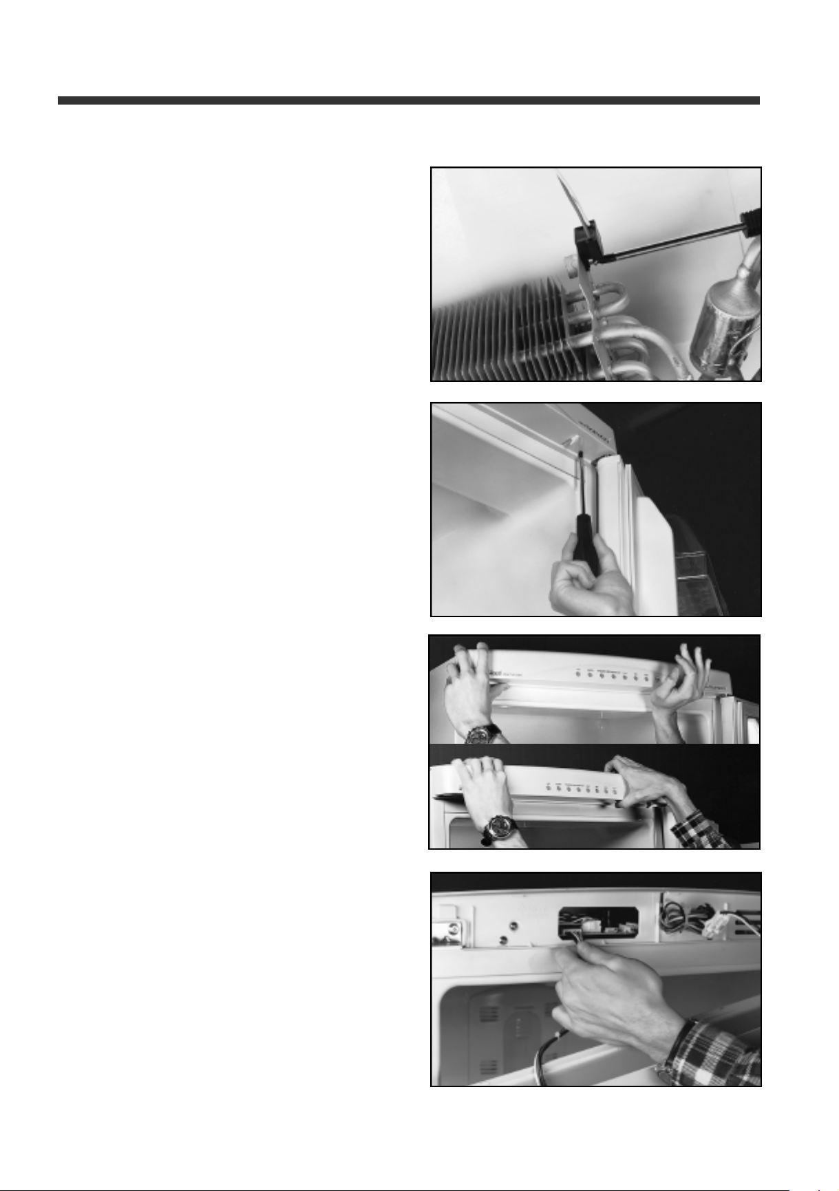
6. Evaporator
1. ERF-310A, 340A, 370A, 310M,
340M, 370M
Components disassembly pictures
1) Detach Fuse Temp and Defrost Heater harness
using a flat screwdriver.
2) Detach Swich Bi-Metal (M-type) or D-sensor
(A-type) harness by pressing the housing
with the fingers
3) Remove 2 welded points
1 3
Page 14

Components disassembly pictures
4) Remove 2 evaporator fixing screws
5) Extract evaporator forward with minimising the
pipe deformation after grasping the both sides of
evaporator and pulling accumulator slighty forward
7. Defrost Heater
1. ERF-310A, 340A, 370A, 310M,
340M, 370M
1) Remove the cable tie
2) Bend 2 small aluminium fixture ribs with
a screwdriver
1 4
Page 15

3) Bend the big aluminium fixture rib by hand
4) Take out Defrost Heater
Components disassembly pictures
8. Fuse Temp
1. ERF-310A, 340A, 370A, 310M,
340M, 370M
1) Open the rib with a screwdriver and
take out Fuse Temp
9. D-Sensor
1. ERF-310A, 340A, 370A
1) Open the rib with the hand and take out D-Sensor
1 5
Page 16
Components disassembly pictures
10. Switch Bi-Metal
1. ERF-310M, 340M, 370M
1) Remove fixing screw with a screwdriver
11. Control Panel
1. ERF-310A, 340A, 370A
1) Remove 2 fixing screws
2) Take out panel Control by pulling it up and forward
3) Detach F Pcb Harness by pulling it forward
1 6
Page 17
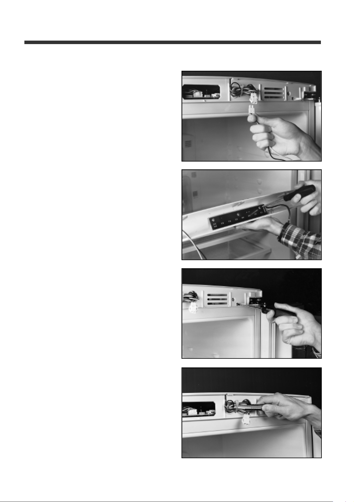
4) Detach Switch Lamp Harness by pressing the
housing with the fingers
5) Remove 3 fixing screws to take out F Pcb
Components disassembly pictures
6) Remove 3 front and 2 upper screws to take out
Base Control Panel
7) Cut cable tie
1 7
Page 18
Components disassembly pictures
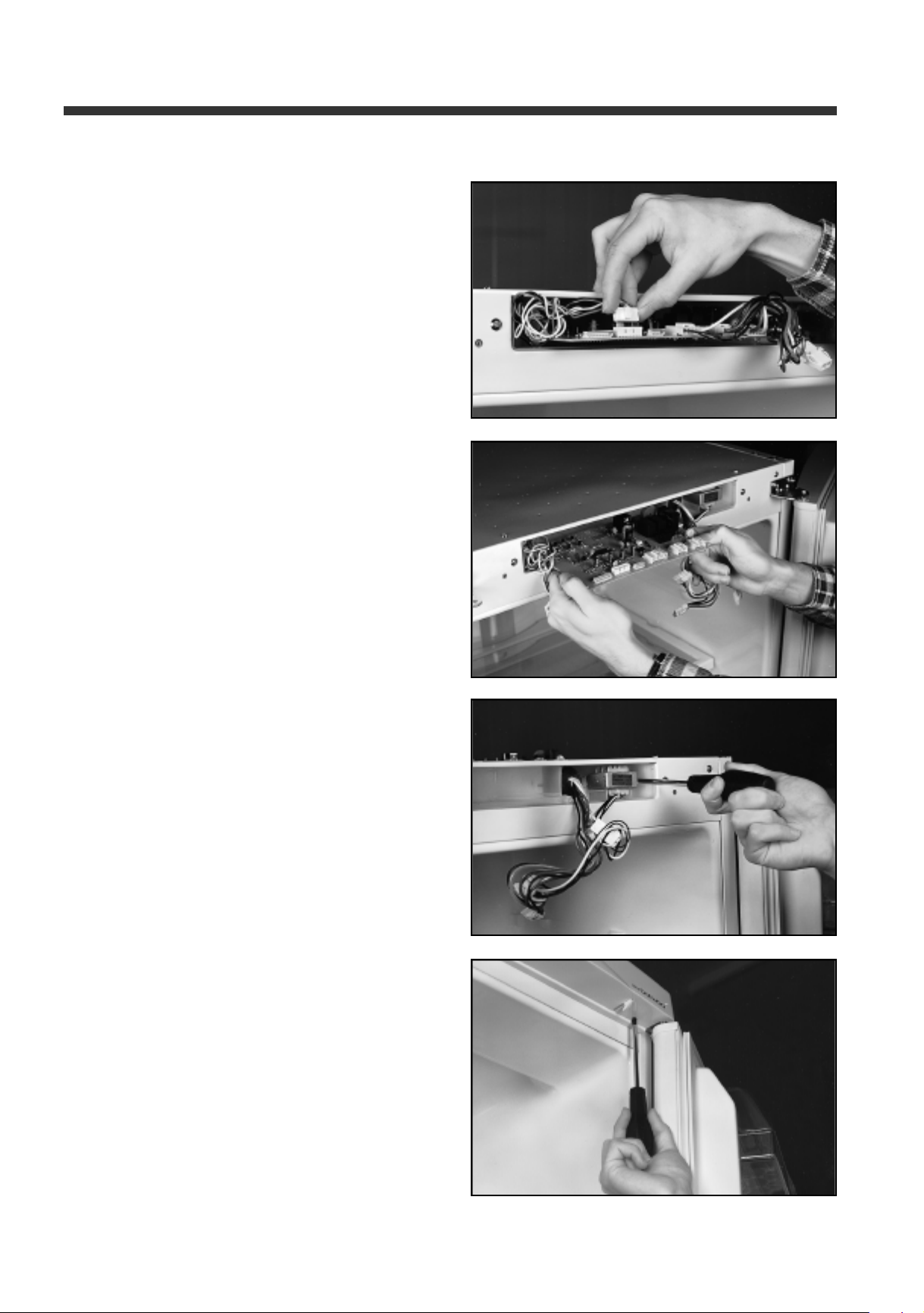
8) Detach Main Pcb Harness by pulling forward
all the housings
9) Take out Main Pcb
10) Remove 2 screws to take Down Trans out
2. ERF-310M, 340M, 370M
1) Remove 2 fixing screws
1 8
Page 19
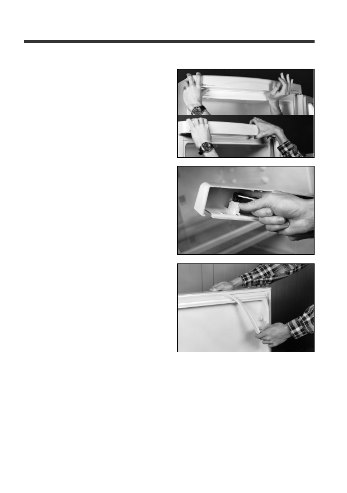
2) Take out Panel Control by pulling it up and forward
and detach Switch Lamp harness by pressing
the housing with fingers
12. Door Switch
1. ERF-310A, 340A, 370A, 310M,
340M, 370M
Components disassembly pictures
1) Remove the door switch sliding by its guide
13. Gasket
1. ERF-310A, 340A, 370A, 310M,
340M, 370M
1) Take off the gasket as shown
2) Fix the new one
1 9
Page 20
Components disassembly pictures
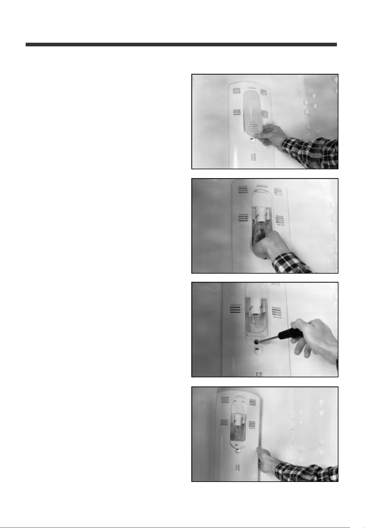
14. Cover Multi Duct
1. ERF-310A, 340A, 370A, 310M,
340M, 370M
1) Remove the Window by pushing lower part upward
and pulling forward
2) To replace the lamp unscrew it, if it is out of order
3) Remove 3 fixing screws
4) Pull forward with instant force
2 0
Page 21
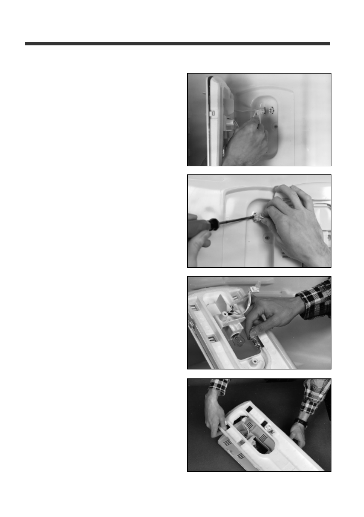
5) Remove the Socket Lamp harness by pressing the
housing with fingers
6) Remove Thermostat (M-type) or R-Sensor (A-type)
harness by pressing the rib with a screwdriver
Components disassembly pictures
7) Remove the aluminium tape
8) Remove Insulator Multi Duct
2 1
Page 22
Components disassembly pictures
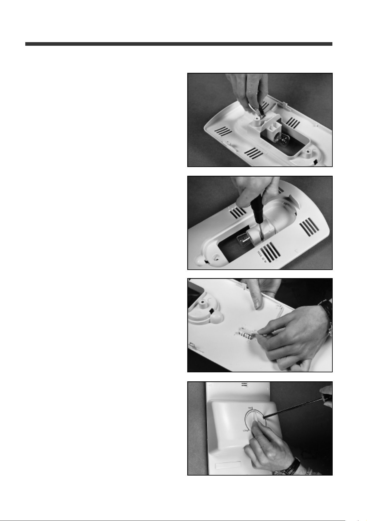
15. Socket Lamp
1. ERF-310A, 340A, 370A, 310M,
340M, 370M
1) Remove harness housing by pulling back
2) Remove 2 fixing screws with a screwdriver
16. R-Sensor
1. ERF-310A, 340A, 370A
1) Take out R-sensor
17. Thermostat
1. ERF-310M, 340M, 370M
1) Take out temperature Knob Control Switch by a flat
screwdriver
2 2
Page 23
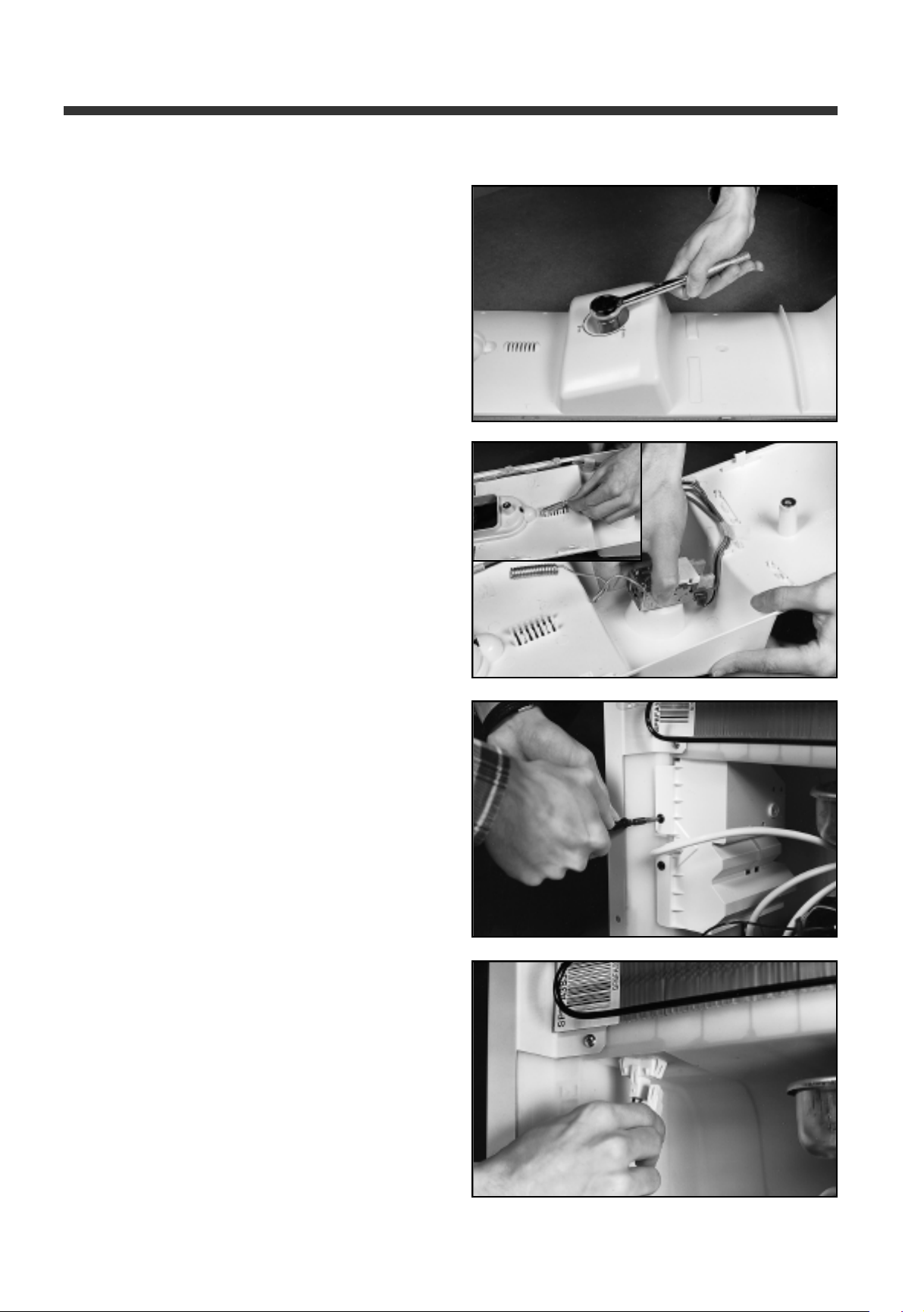
2) Remove special nut by unscrewing it
3) Take out thermostat
Components disassembly pictures
18. Box Power
1. ERF-310A, 340A, 370A
1) Unscrew Box Power with special tool. To take it
pull down and then forward.
* It must be handled by authorized technicians
2) Take out harness with a screwdriver
2 3
Page 24
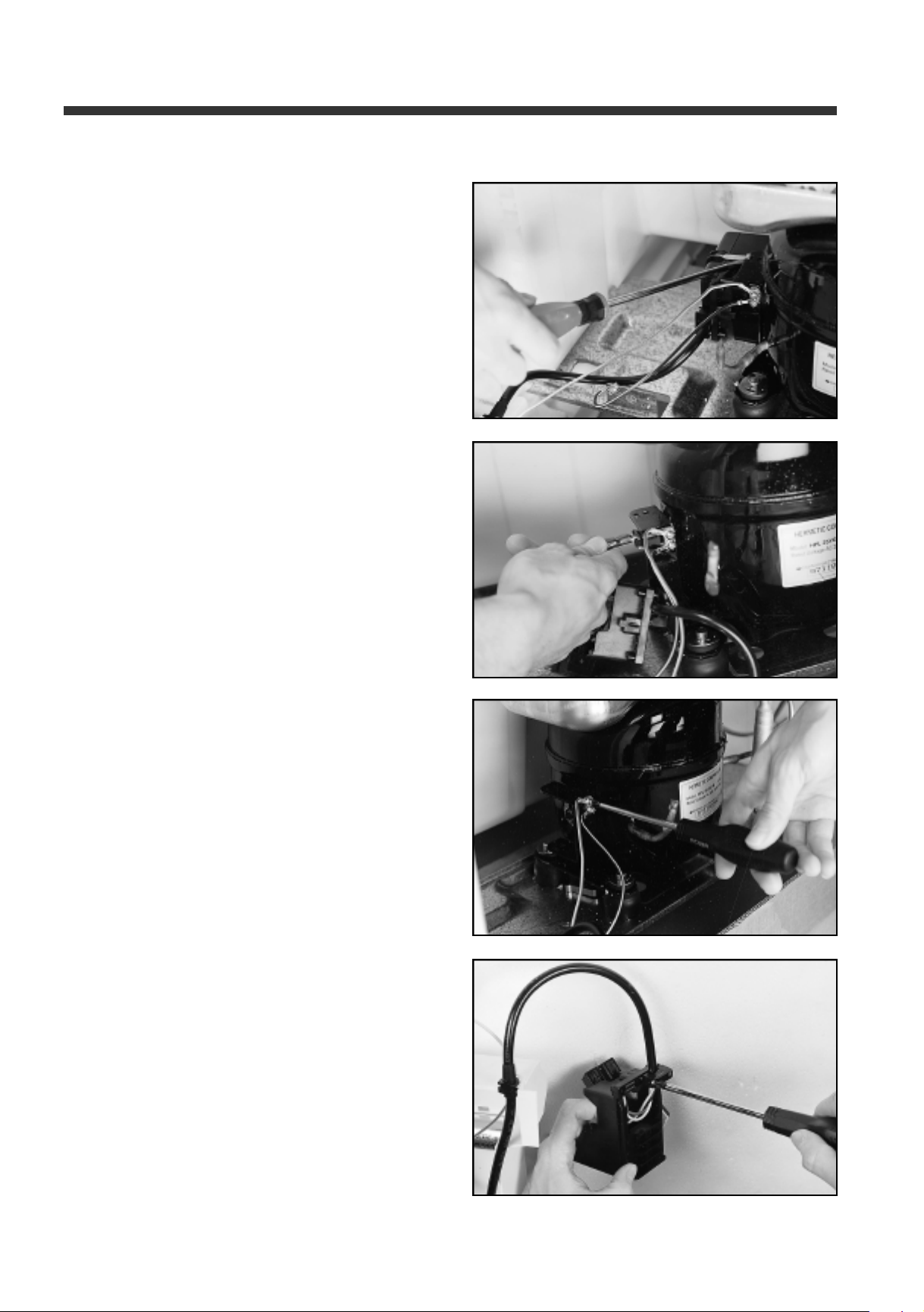
Components disassembly pictures
3) Take out Relay band to remove relay cover
4) Detach PTC and OLP housings with fingers
5) Remove earth harness fixing screws with
a screwdriver
6) Unscrew Relay Harness from Relay Box
2 4
Page 25
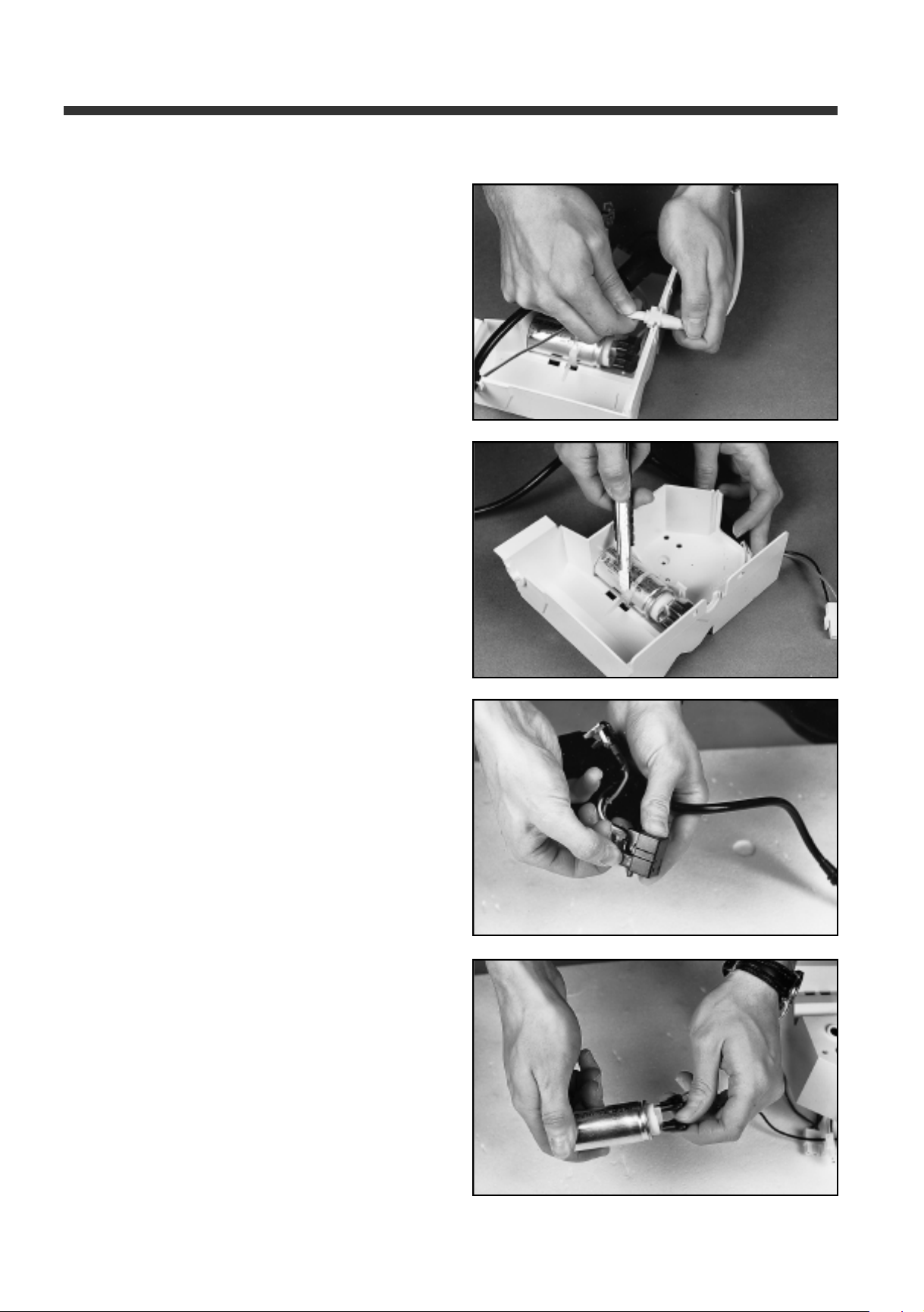
7) Take out Relay Harness and earth harness
from their housings
8) Cut Condenser fixing cable tie and take
out condenser
Components disassembly pictures
9) Detach OLP and PTC housings from Relay harness
10) Detach Relay harness from Condenser
2 5
Page 26
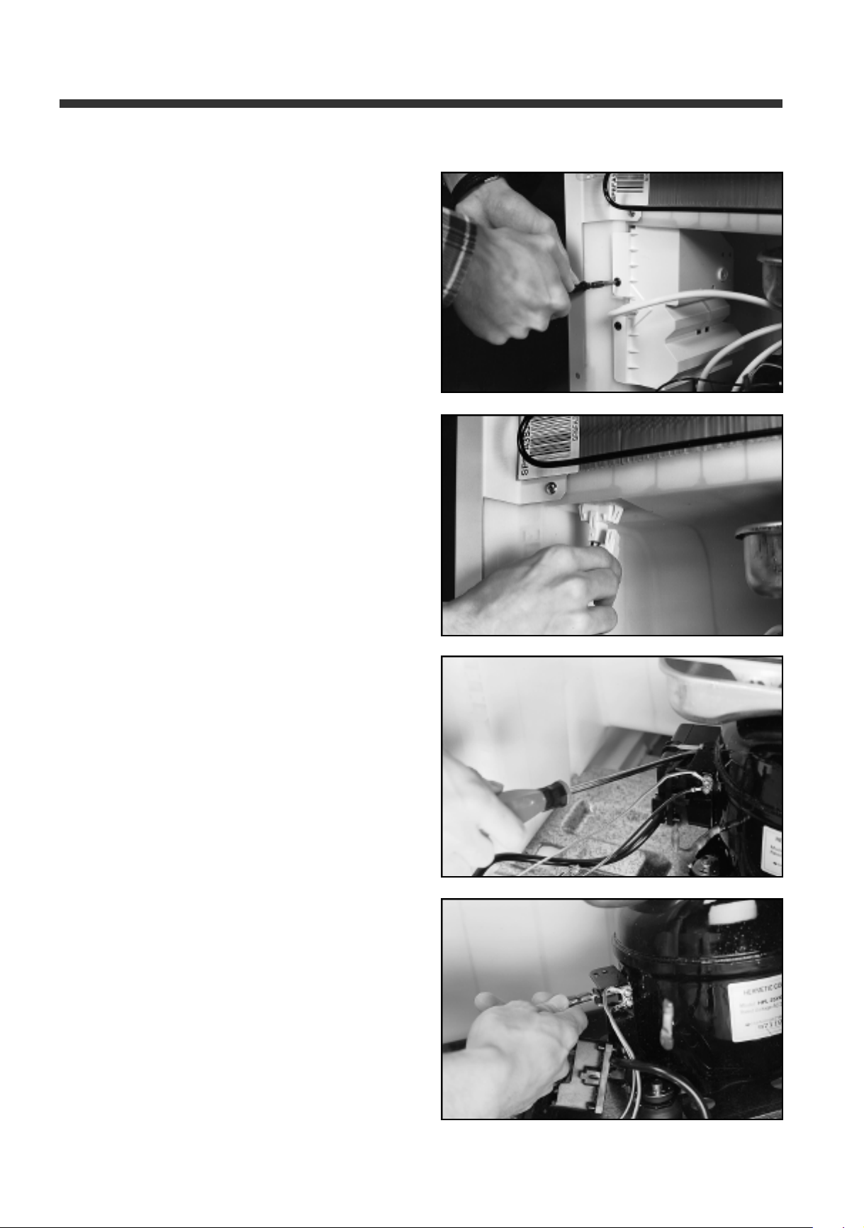
Components disassembly pictures
2. ERF-310M, 340M, 370M
1) Unscrew Box Power. To take it out pull down
and then forward
* It must be handled by authorized technicians
2) Take out harness with a screwdriver
3) Take aut Relay Band to remove Relay cover
4) Detach PTC and OLP housings with fingers
2 6
Page 27
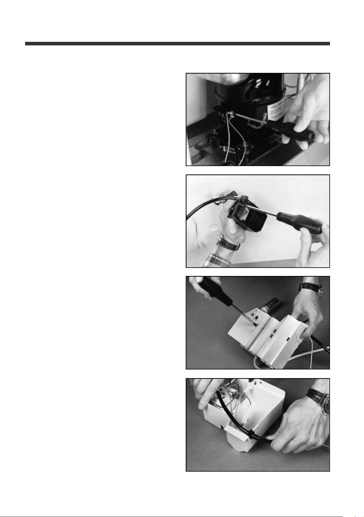
5) Remove earth harness fixing screws
with a screwdriver
6) Unscrew Relay Harness from Relay Box
Components disassembly pictures
7) Take out D-Timer fixing screw
8) Take out Relay Harness and earth harness from
their housings
2 7
Page 28
Components disassembly pictures
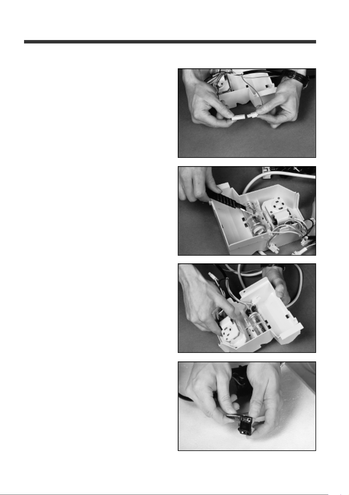
9) Detach power Cord harness by pressing fixture
housing with the fingers
10) Cut Condenser fixing cable tie
11) Take out D-Timer and Condenser
12) Detach OLP and PTC housings from Relay harness
2 8
Page 29
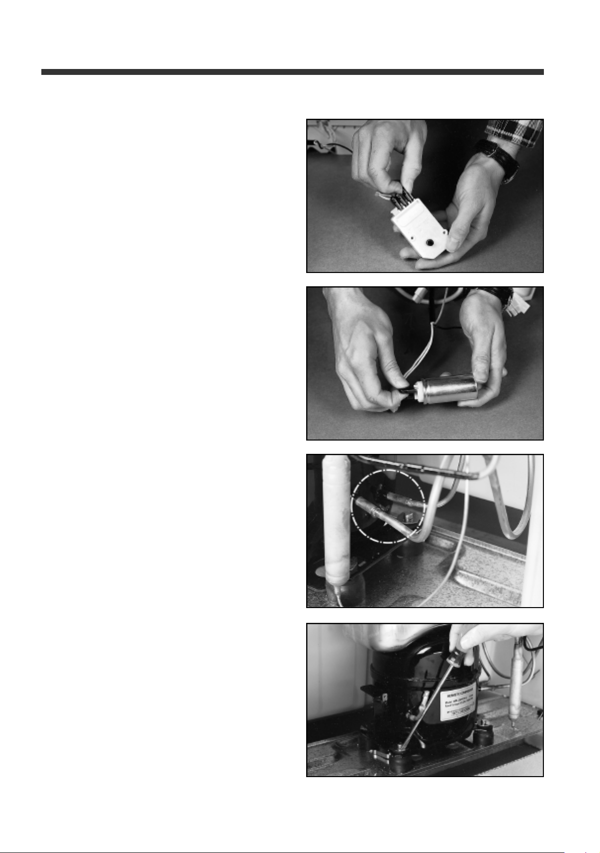
13) Detach D-Timer housings from Relay harness
14) Detach Relay harness from Condenser
Components disassembly pictures
19. Compressor
1. ERF-310A, 340A, 370A, 310M,
340M, 370M
1) Remove 2 welded points
2) Take out the four compressor fixture with a
flat screwdriver
2 9
Page 30
Components disassembly pictures
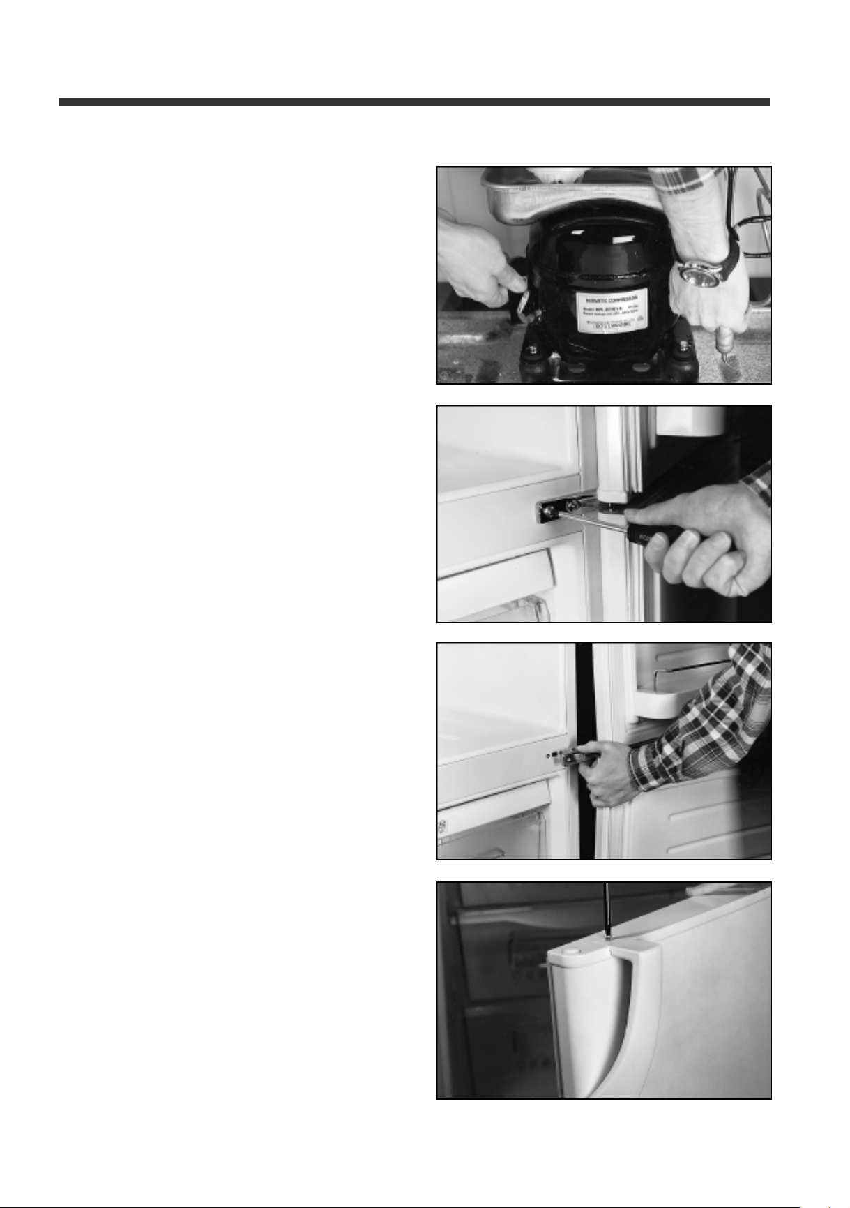
3) Take out compressor
20. Reverse doors
1. ERF-310A, 340A, 370A, 310M,
340M, 370M
1) Remove 2 screws to take out Medium Hinge
2) Take out freezer and refrigerator doors
at the same time
3) Remove Handle fixing screws and change them
from one door to the other
3 0
Page 31
4) Take out Cap door bushings and change them
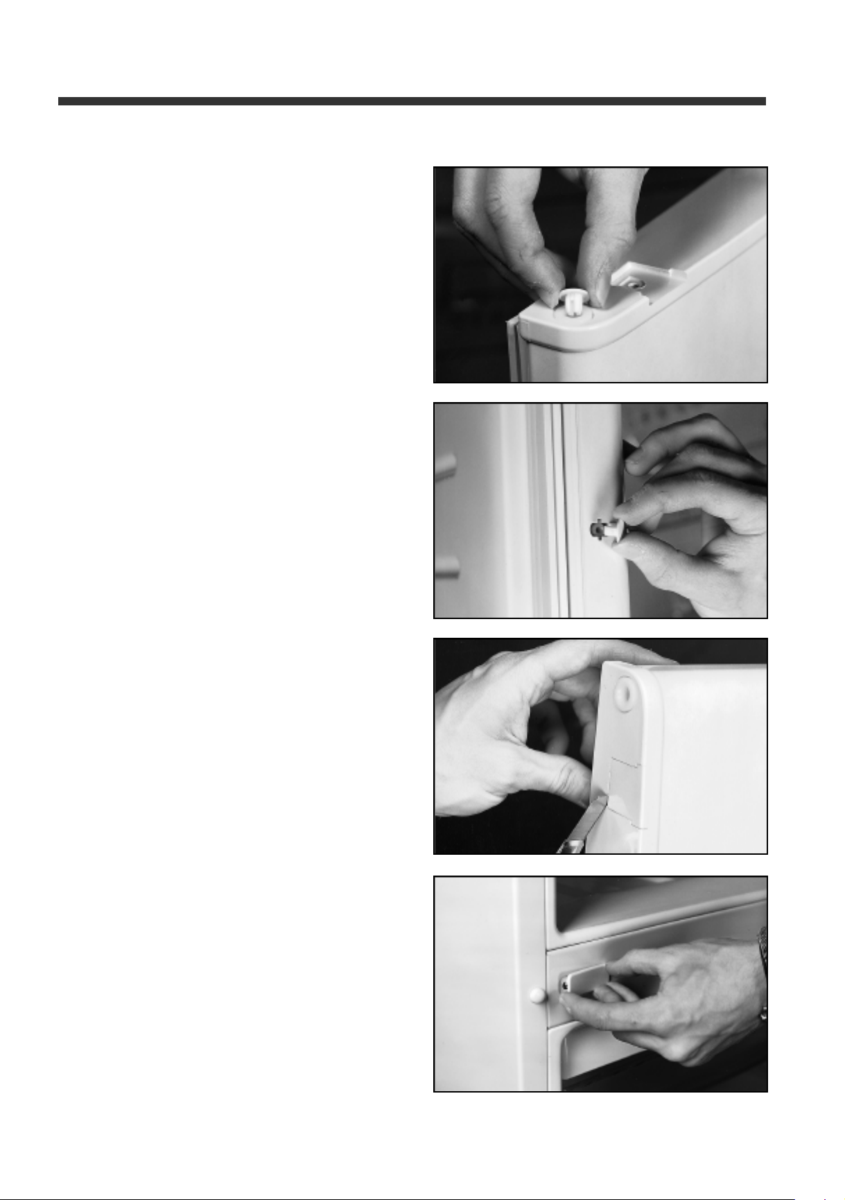
to the other side of the door
5) Take out Cap handles and changes to the other
side of the door
Components disassembly pictures
6) Take out Cover door caps and move them from
one door to the other
7) Take out cap screw hole and move to the
other side
3 1
Page 32
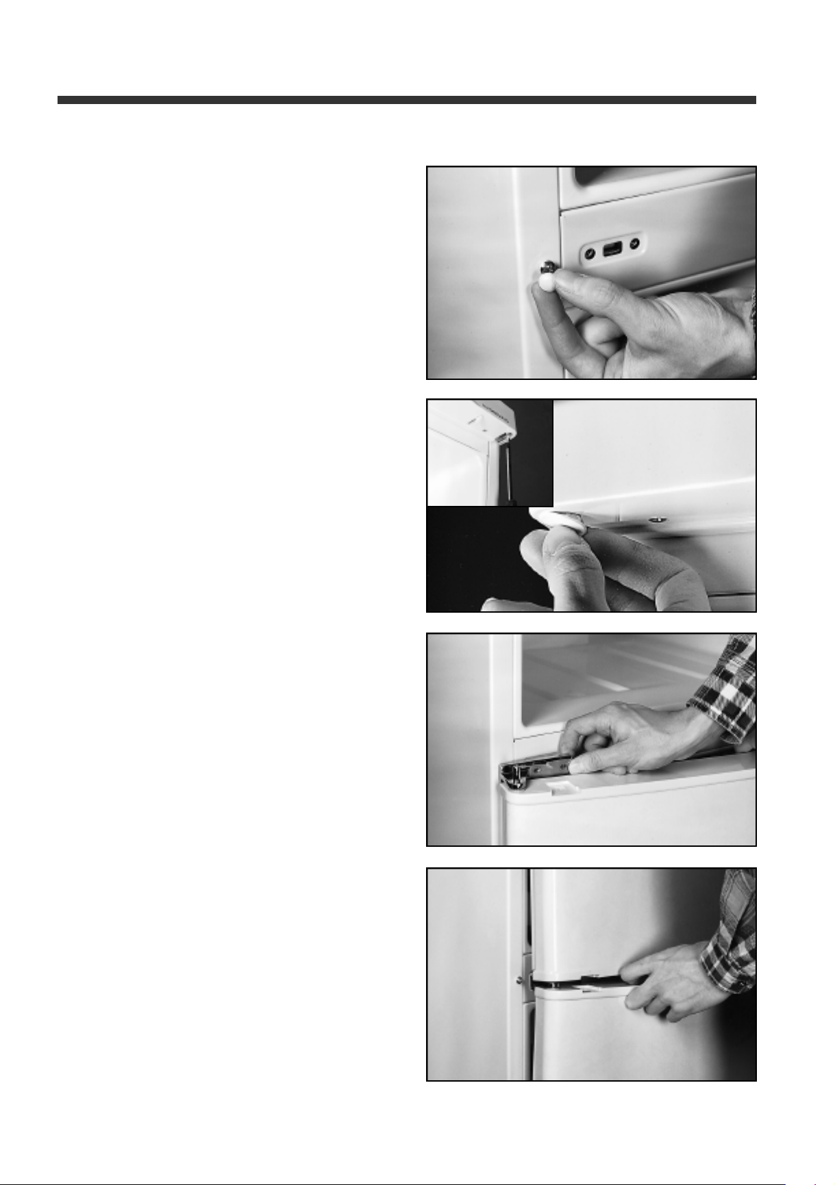
Components disassembly pictures
8) Take out Cap screw and move to the other side
9) Take out Top and Under Hinges with a screwdriver
and change them to the other side. Take out Cap
Control Panel and move to the other side
10) Assembly Freezer door in the Under hinge and put
the Medium hinge without screwing it
11) Assembly Refrigerator door; First the Top hinge and
then the Medium hinge. After this screw the
Medium hinge
3 2
Page 33
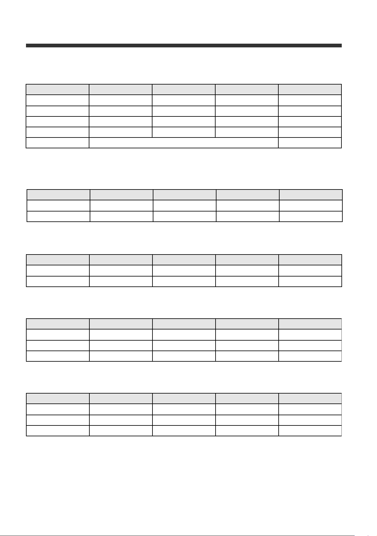
9. COMPONENTS SPECIFICA -
1. COMPRESSOR
ERF-310A/M ERF-340A/M ERF-370A/M Remarks
Part name HPL25YG1-5 <– HPL27YG1-5
Part code 39561125R51 <– 39561127R51
Rated voltage 220-240V 50Hz <– <–
Starting type RSIR <– <–
Refrigerant R134 a
2. RELAY ASSEMBL Y
2.1 PTC
ERF-310A/M ERF-340A/M ERF-370A/M Remarks
Part name PTH490D-AS330 <– <–
Part code 3817907000 <– <–
2.2 OLP
ERF-310A/M ERF-340A/M ERF-370A/M Remarks
Part name 4TM213NHBYY <– 4TM265NHBYY
Part code 3817911200 <– 3817911300
3. RUNNING CAPACITOR
ERF-310A/M ERF-340A/M ERF-370A/M Remarks
Part name MA80040040 <– MA80050040
Specifications 4uF 400VAC <– 5uF 400VAC
Part code 3016400800 <– 3016400810
4. AS MOTOR FAN
ERF-310A/M ERF-340A/M ERF-370A/M Remarks
Part name IS-23211DWBFH <– <–
Specifications 2400RPM <– <–
Part code 3015903700 <– <–
3 3
Page 34
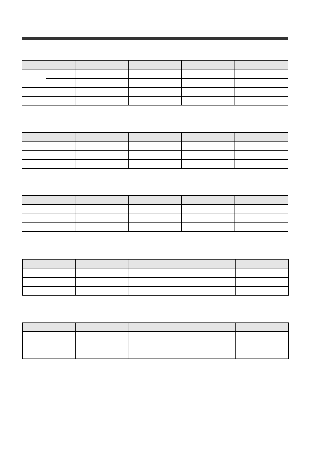
Component specifi -
5. HEATER D AS
ERF-310A/M ERF-340A/M ERF-370A/M Remarks
Part RICA RS6 <– <–
Name CONSONI 16 <– <–
Specifications 230V 230W <– <–
Part code 3012803600 <– <–
6. LAMP
ERF-310A/M ERF-340A/M ERF-370A/M Remarks
Type Pygmy <– <–
Specifications 230V 15W <– <–
Part code 3013600700 <– <–
7. SWITCH LAMP
ERF-310A/M ERF-340A/M ERF-370A/M Remarks
Part name 1051 <– <–
Specifications 250V 0.25A <– <–
Part code 3018111500 <– <–
8. SOCKET LAMP AS
ERF-310A/M ERF-340A/M ERF-370A/M Remarks
Part name 1058 <– <–
Specifications 250V 2A <– <–
Part code 3017903100 <– <–
9. FUSE TEMPERATURE
ERF-310A/M ERF-340A/M ERF-370A/M Remarks
Part name SF76E <– <–
Specifications 250V 15(10)A <– <– 77ºC
Part code 3017200700 <– <–
3 4
Page 35
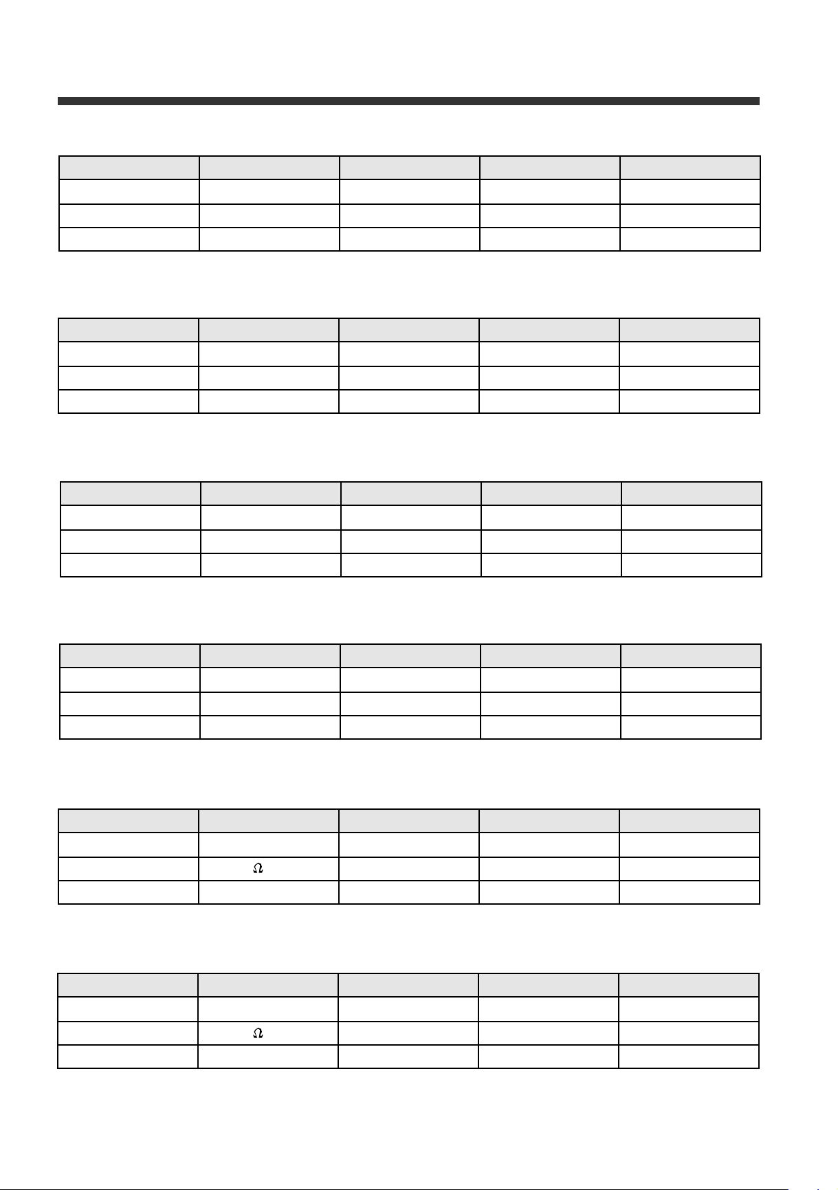
10. SWITCH BI-METAL
ERF-310M ERF-340M ERF-370M Remarks
Part name 261N <– <–
Specifications 250V 10(3)A <– <–
Part code 3018115600 <– <–
11. SWITCH D TIMER
ERF-310M ERF-340M ERF-370M Remarks
Part name TMDE807UC1 <– <–
Specifications 9h 37 min <– <–
Part code 3018115700 <– <–
12. THERMOST AT
Component specifi -
ERF-310M ERF-340M ERF-370M Remarks
Part name K50-P1530 <– <–
Specifications 250V 6A <– <–
Part code 3018300300 <– <–
13. DOWN TRANS AS
ERF-310A ERF-340A ERF-370A Remarks
Part name ERF-310 <– <–
Specifications 230V / 50Hz <– <–
Part code 5EPK041009 <– <–
14. SENSOR R AS
ERF-310A ERF-340A ERF-370A Remarks
Part name TH310G34GBNR <– <–
Specifications 30 K (AT 0ºC) <– <–
Part code 3014801800 <– <–
15. SENSOR D AS
ERF-310A ERF-340A ERF-370A Remarks
Part name TH310G34GBNR <– <–
Specifications 30 K (AT 0ºC) <– <–
Part code 3014801700 <– <–
3 5
Page 36
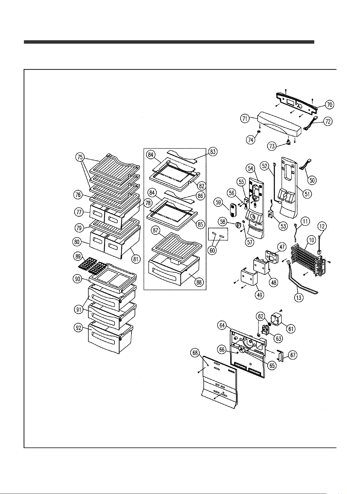
10. EXPLODE DRA -
1. ERF-310M, ERF-340M, ERF-370M
3 6
Page 37
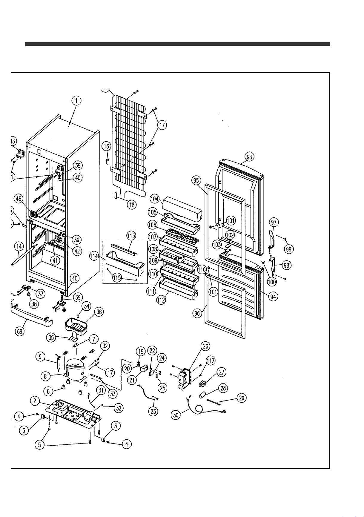
Explode drawings
3 7
Page 38
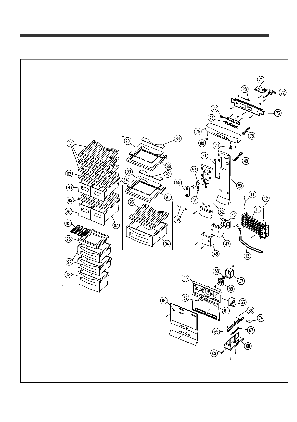
Explode drawings
2. ERF-310A, ERF-340A, ERF-370A
3 8
Page 39
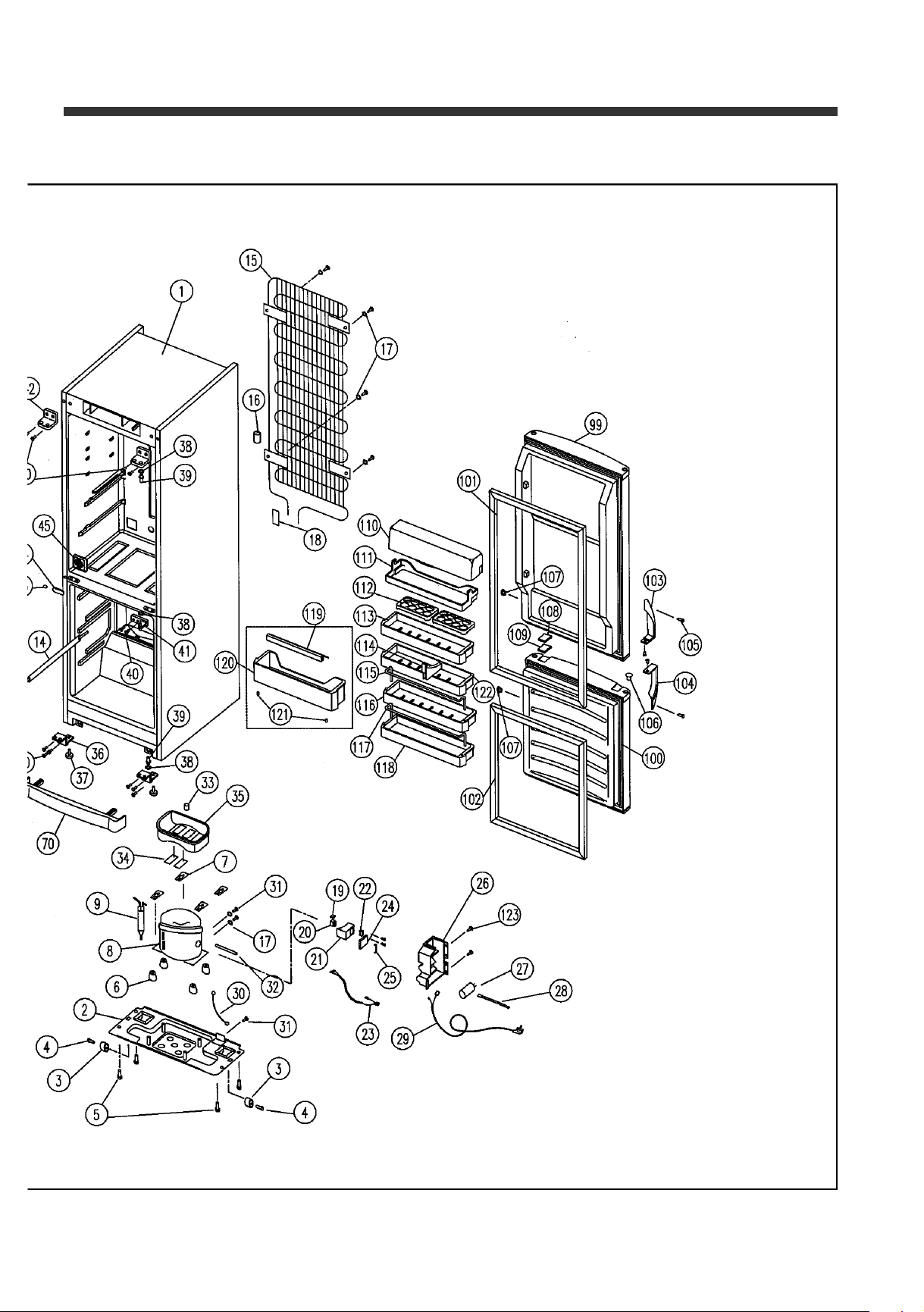
Explode drawings
3 9
Page 40
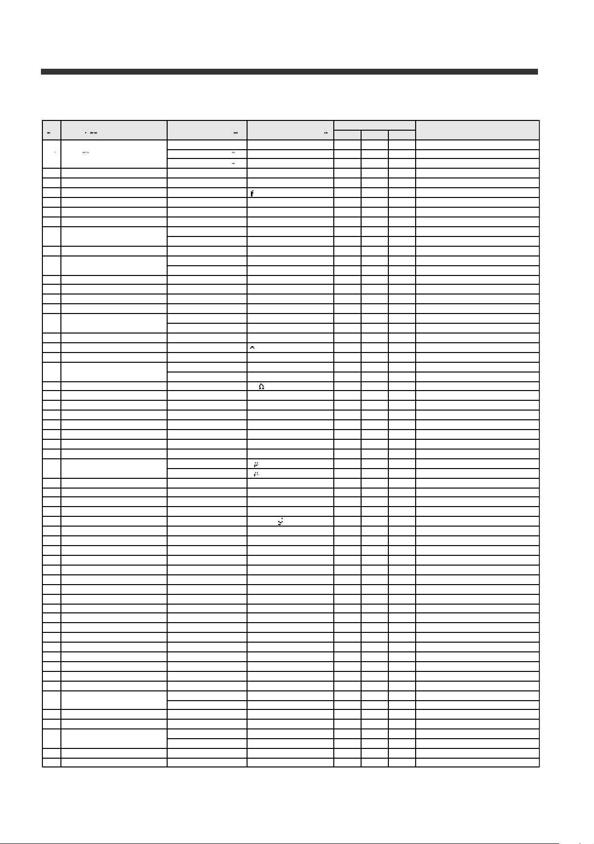
11. PA RT LIST
1. Parts list (M TYPE)
4 0
Page 41
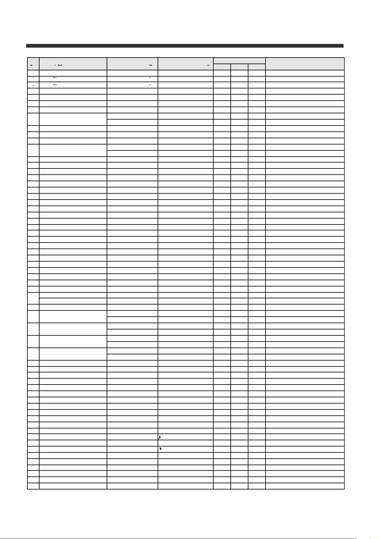
Part List
4 1
Page 42
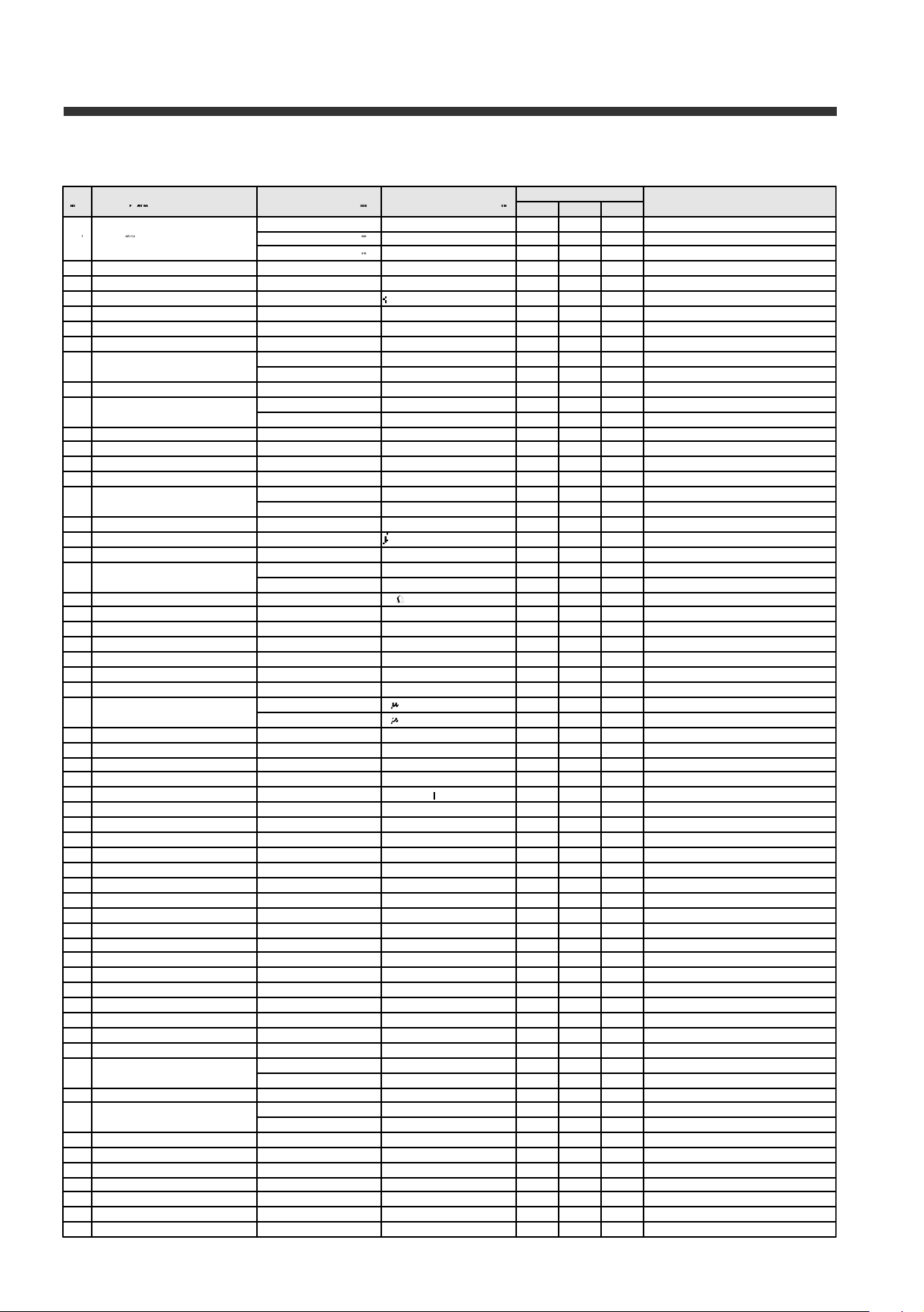
Part List
2. Parts list (A TYPE)
4 2
Page 43
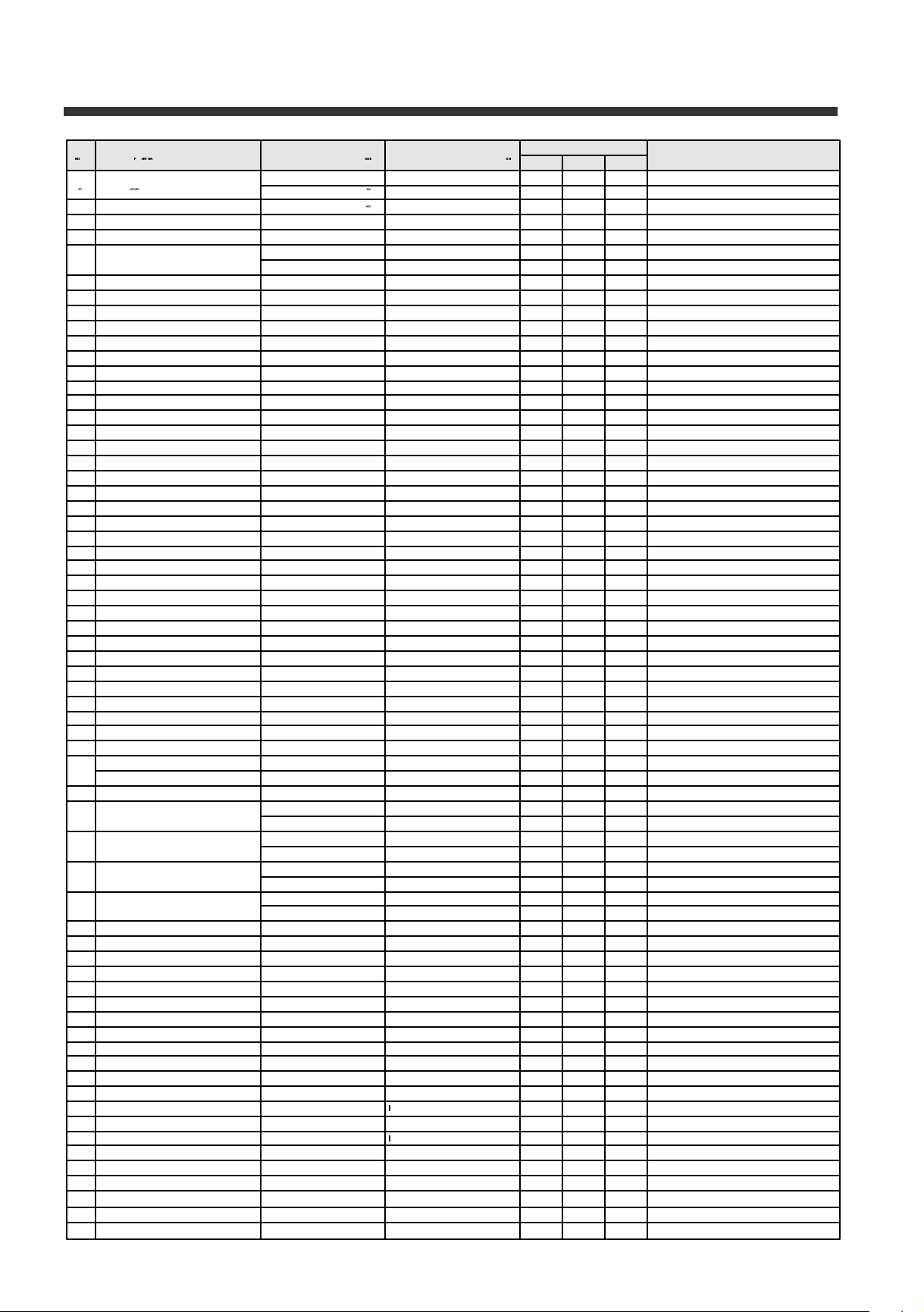
Part List
4 3
Page 44
12. PCB CONTROL F U N C -
PCB SERVICE MANUAL OF ELECTRONIC CONTROL TYPE
Model: ERF-310A/340A/370A
1. How to use the panel
NO CONTROL FUNCTION CONTENTS
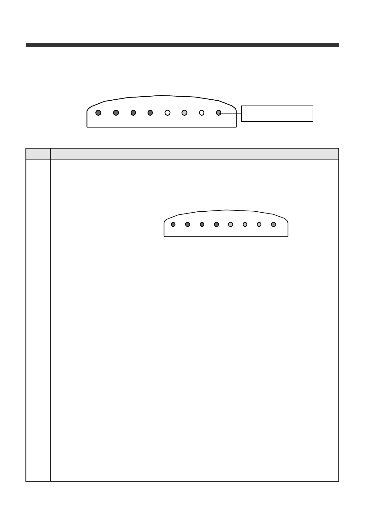
1. Initial Operation 1) In the Initial Operation, the Temperature of Refrigerator set MID
Position.
2) Freezer and Refrigerator LED is ON with Red color.
3) Vacation or Super Freezing LED depends on Position of Freezer
Control knob.
2. Panel Display 1) VAC ON: When the Control Knob in the freezer is locationed
Vacation position.
2) SUPER ON: When the Control knob in the freezer is locationed
Freezing position.
3) FREEZER LED
GREEN ON: When the freezer temp. is OK (less than -5 deg
at D sensor)
RED ON: When the freezer temp. is not good.
NG condition (1 OR 2)
1- More than -5 deg at D-sensor when comp. off
2- More than -5 deg when comp is running for 120 min.
cf. ERROR DISPLAY
RED LED ON/OFF one times: D1 ERROR
It is D sensor error for open or short
RED LED ON/OFF two times: D2 ERROR
Defrost Error is ocurred that heater off by timer for 80 min.
4) REFRIGERATOR LED
GREEN ON: When the refrigerator temp. is OK, (-7˜10 deg)
RED ON : When the refrigerator temp. is not good.
NG condition (1 and 2)
1- More than 10 deg OR Less than -7 deg at R-sensor
2- More than 120 min.
cf. ERROR DISPLAY
RED LED ON/OFF one times: R1 ERROR
It is R sensor error for open or short
5) LOW ON: When the comp is controled by Low on/off condition
6) MID ON: When the comp is controled by Mid on/off condition
4 4
Page 45
Pcb Control Functions
NO CONTROL FUNCTION CONTENTS
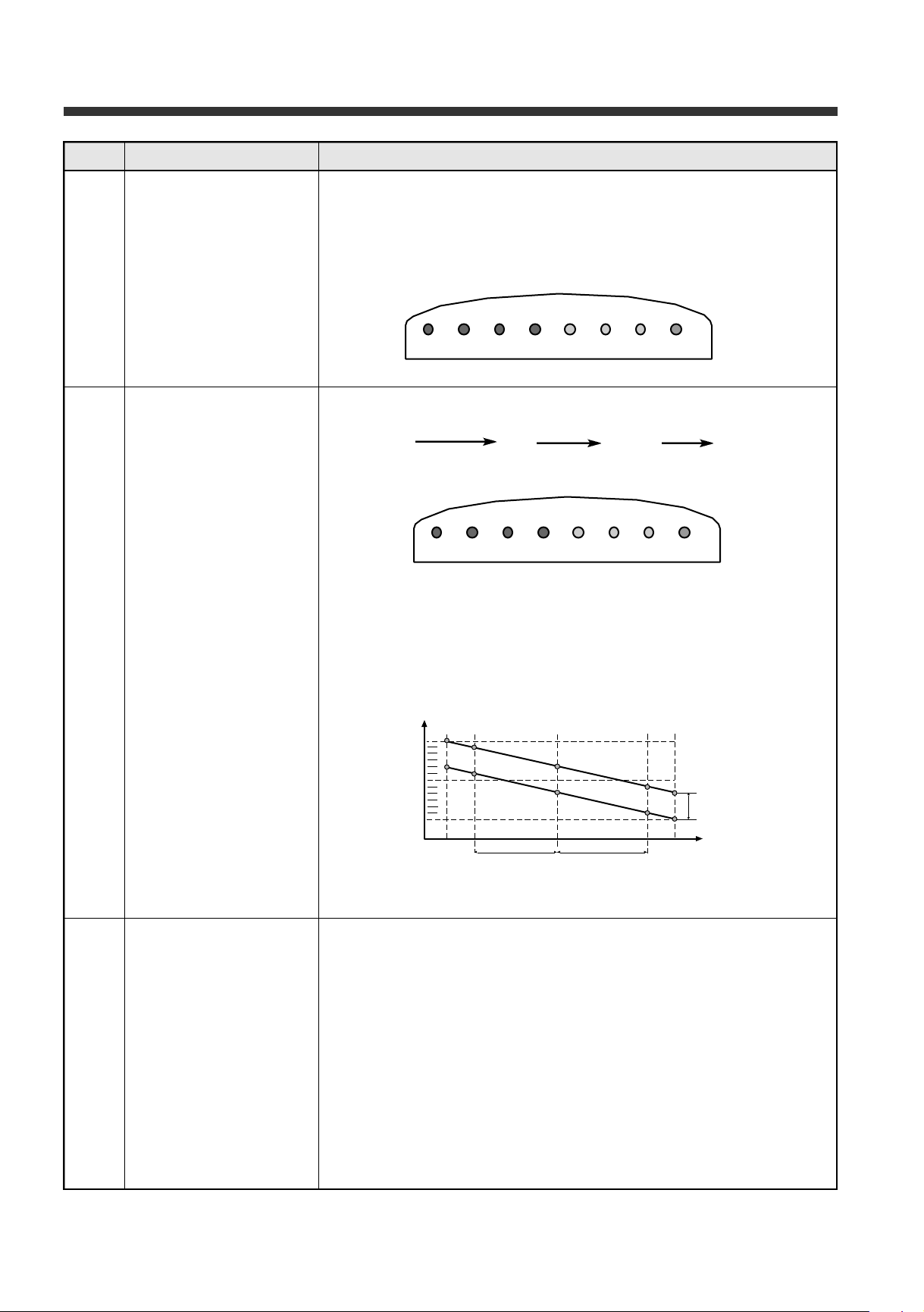
2. Panel Display 7) HIGH ON: When the comp is controled by High on/off condition.
cf. LOW / MID / HIGH LED ALL ON: This is Continuty MODE that
Comp/ Fan is ON without Sensor temp.
3. Refrigerator Temperature 1) Temperature can be controled by 3 steps with the Refrigerator
Control temperature button.
LOW MID HIGH LOW
2) Refrigerator Control ON/OFF temperature
1- MID OFF point: -2 deg
2- ON/ OFF DIFF: 4 deg
3- STEP DIFF: 3 deg
3) Delay time of Fan is 1 MIN after compressor on/off
4. Determination of Defrost 1) Detemination of Defrost mode
1- Accumulated running time of compressor
2- Accumulated Open Times of R-door
3- Total time (On time of compressor + Off time of compressor)
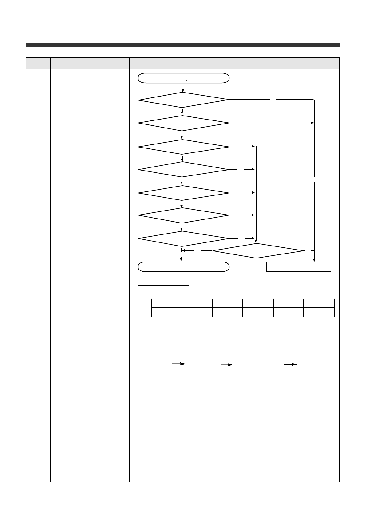
2) Starting condition of Defrost mode
I. When Accumulated Running Time of compressor (1) is 10 hours
II. When Accumulated Open Times of R-door (2) is more than 3 times
III. Check After (I) condition, if the (II) condition is more than 3 times
then Star Defrost mode.
I V. When Accumulated Running Time of compressor (1) is 15 hours,
Star Defrost mode.
V. Finally, when Total time (3) is more than 60 hours, Star
Defrost mode.
4 5
Page 46
Pcb Control Functions
NO CONTROL FUNCTION CONTENTS
5. Flow chart for
Determination of Defrost
6. Defrost Mode • General Defrost
1) START: By determination defrost condition
start 10 11 12 13 14 15
2) FLOW
H E AT E R PA U S E ( 4 m i n . ) FAN DELAY(4 min.) CONTROL
1- HEATER
*On - When defrost condition mode is started.
*Off - When D-sensor is more than 10 deg.
If D1 ERROR is existance, Heater off by Time
* LIMIT TIME -80min (D2 ERROR) Case of Heater/Temp Fuse Open
If D1 ERROR is existance, Heater off by 30 min.
* HTR 30 SEC ON: To check DEFROST CURRENT (HEATER) in the
mass production line
2- PAUSE
* Time - 4 min.
* All devices are off
3- FAN DELAY
* Time - 4 min.
* Only compressor is on in the R-sensor on condition
Accumulated running time of compressor
4 6
Page 47
Pcb Control Functions
Display contents LED on/off Output
D1 ERROR
D2 ERROR
R1 ERROR
NO CONTROL FUNCTION CONTENTS
6. Defrost Mode • Forced Defrost
1) START: Temp Control SW is pushed for 5 sec continuosly
2) FLOW
1- Buzzer for 1 sec.
2. Same of the general Defrost Flow
7. Initial Defrost 1) When Power is on, Check the D-SENSOR Temp.
2) Start Condition: Less than 3.5 deg for D-SENSOR
8. COMP Restart prevent 1) The COMP. cannot be on within 6min. after COMP off.
2) During Pre-cool step in defrost mode. 6 min. dellay is unavailable
9. Alarm function 1) DOOR OPEN: 3 sec. in times every minute
2) TEMP SW: When it is clicked
3) POWER ON
4) FORCED DEFROST
5) FAST TIME SW
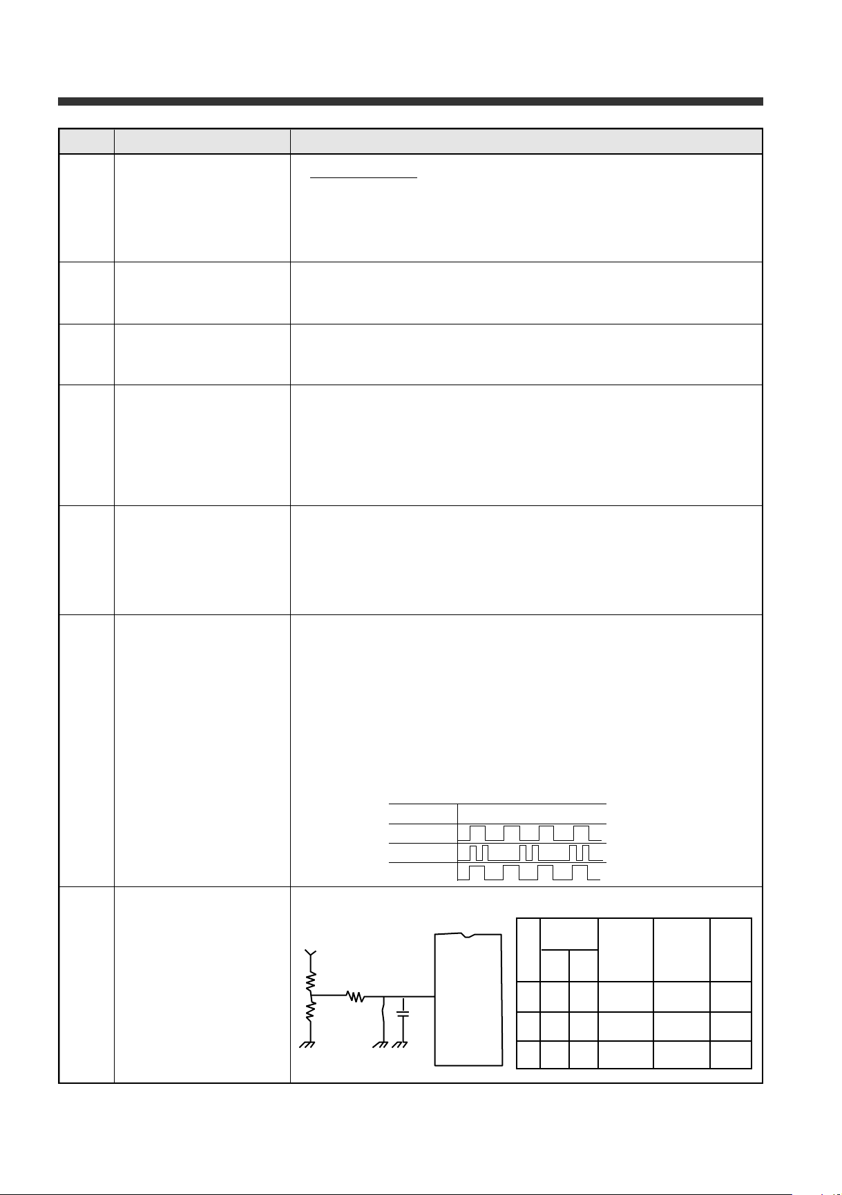
10. Control in R1 Error * In R SENSOR Open/Short error, Compress/Fan are controled by time as
following
Comp/Fan ON TIME: 20 min.
Comp/Fan OFF TIME: 30 min.
11. Error Code 1) D1 Error
* Display: FREEZER RED LED on/off one times.
* Condition: It is occured when D sensor is open or short.
2) D2 Error
* Display: FREEZER RED LED on/off two times.
* Condition: D2 Error is occured that heater off by timer for 80 min.
3) R1 Error
* Display: REFRIGERATOR RED LED on/off one times.
* Condition: It is occured when R sensor is open or short
12. OPTION Protection of OVER-COOL in CRISP
4 7
Page 48
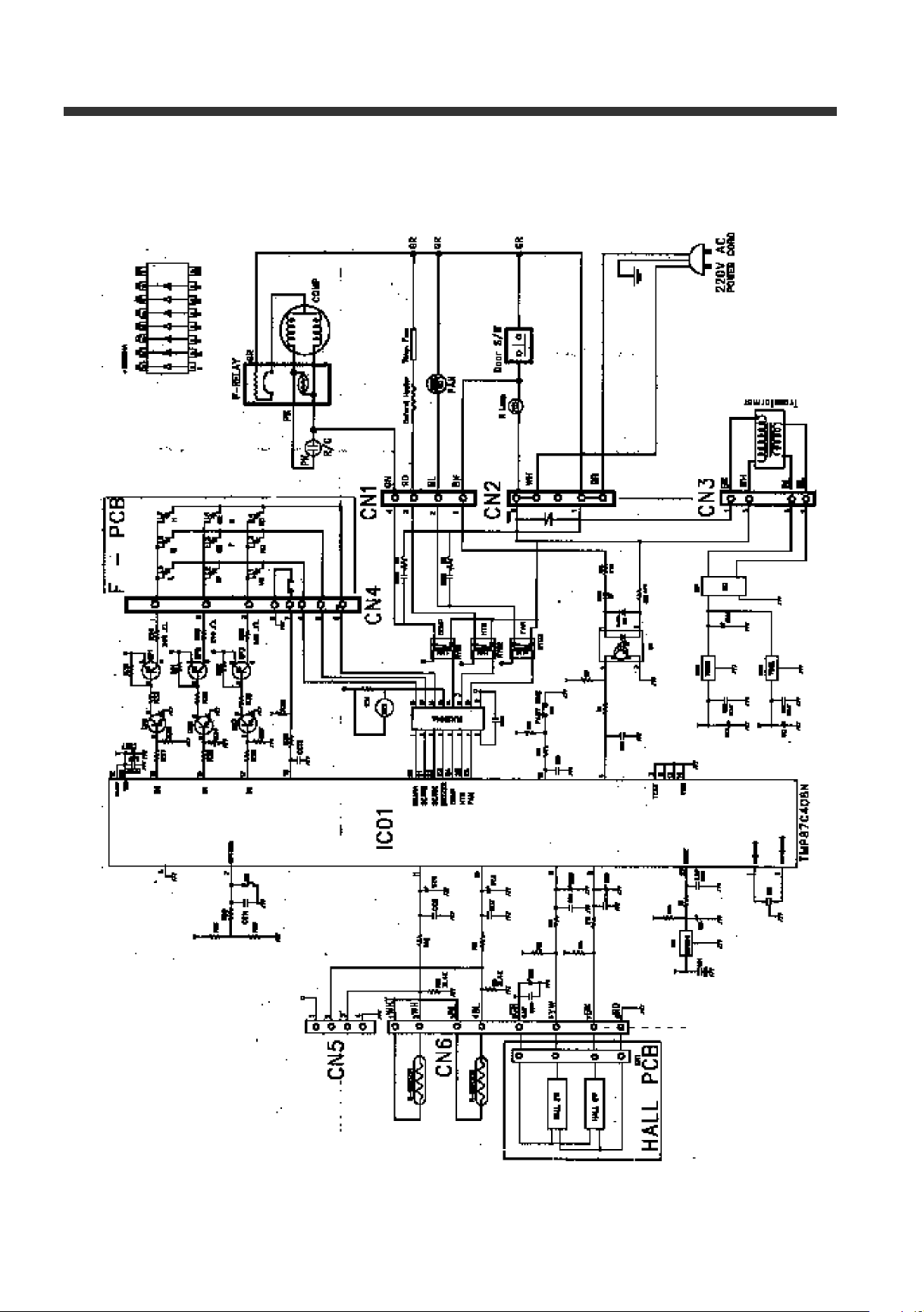
13. MAIN PCB DIA -
4 8
 Loading...