


1. SPECIFICA TIONS . . . . . . . . . . . . . . . . . . . . . . . . . . . . . . . . . . . . . . . . . . . . . . . . . . . . . . . . . . . . . . . . . 2
2. FEA TURE AND TECHNICAL EXPLANATION . . . . . . . . . . . . . . . . . . . . . . . . . . . . . . . . . . . . . . . . . . . 3
THE FEA TURE OF THE WASHING MACHINE . . . . . . . . . . . . . . . . . . . . . . . . . . . . . . . . . . . . . . . 3
WATER CUURENTS TO ADJUST THE UNBALANCED LOAD . . . . . . . . . . . . . . . . . . . . . . . . . . 3
FUNCTION FOR SOAK WASH . . . . . . . . . . . . . . . . . . . . . . . . . . . . . . . . . . . . . . . . . . . . . . . . . . . 3
AUTIMA TIC WATER SUPPLY SYSTEM FOR BLANKET WASH . . . . . . . . . . . . . . . . . . . . . . . . . 3
PULSA TOR SYSTEM . . . . . . . . . . . . . . . . . . . . . . . . . . . . . . . . . . . . . . . . . . . . . . . . . . . . . . . . . . . 4
AUTOMATIC DRAINING TIME ADJUSTMENT . . . . . . . . . . . . . . . . . . . . . . . . . . . . . . . . . . . . . . . 4
SOFTENER DISPENSER . . . . . . . . . . . . . . . . . . . . . . . . . . . . . . . . . . . . . . . . . . . . . . . . . . . . . . . . 5
AUTOMATIC UNBALANCE ADJUSTMENT . . . . . . . . . . . . . . . . . . . . . . . . . . . . . . . . . . . . . . . . . 6
CIRCULA TING-WATER COURCE AND LINT FILTER . . . . . . . . . . . . . . . . . . . . . . . . . . . . . . . . . 6
RESIDUAL TIME DISPLA Y . . . . . . . . . . . . . . . . . . . . . . . . . . . . . . . . . . . . . . . . . . . . . . . . . . . . . .7
DRAIN MOTOR . . . . . . . . . . . . . . . . . . . . . . . . . . . . . . . . . . . . . . . . . . . . . . . . . . . . . . . . . . . . . . . . 7
GEAR MECHANISM ASS’Y . . . . . . . . . . . . . . . . . . . . . . . . . . . . . . . . . . . . . . . . . . . . . . . . . . . . . .8
PRINCIPLE OF BUBBLE GENERA T OR . . . . . . . . . . . . . . . . . . . . . . . . . . . . . . . . . . . . . . . . . . . . 8
FUNCTIONAL PRINCIPLE OF BUBBLE WASHING MACHINE . . . . . . . . . . . . . . . . . . . . . . . . . 9
. STRUCTURE OF THE WASHING MACHINE . . . . . . . . . . . . . . . . . . . . . . . . . . . . . . . . . . . . . . . . . . . 10
4. FUNCTIONS OF THE CONTROL P ANEL . . . . . . . . . . . . . . . . . . . . . . . . . . . . . . . . . . . . . . . . . . . . . 11
5. DIRECTIONS FOR INST ALLATION AND USE . . . . . . . . . . . . . . . . . . . . . . . . . . . . . . . . . . . . . . . . . 13
HOW TO INSTALL THE WASHING MACHINE . . . . . . . . . . . . . . . . . . . . . . . . . . . . . . . . . . . . . . 13
HOW TO CONNECT THE INLET HOSE . . . . . . . . . . . . . . . . . . . . . . . . . . . . . . . . . . . . . . . . . . . 14
PREP ARATION FOR WASHING . . . . . . . . . . . . . . . . . . . . . . . . . . . . . . . . . . . . . . . . . . . . . . . . . 15
HOW TO INSTALL THE DRAIN HOSE (ONLY PUMP MODEL) . . . . . . . . . . . . . . . . . . . . . . . . . 16
HOW TO CLEAN DRAIN FILTER (ONLY PUMP MODEL) . . . . . . . . . . . . . . . . . . . . . . . . . . . . . 17
6. PROCEDURE OF FULL-AUTOMATIC WASHING . . . . . . . . . . . . . . . . . . . . . . . . . . . . . . . . . . . . . . . 18
7. DIRECTIONS FOR DISASSEMBLY AND ADJUSTMENT . . . . . . . . . . . . . . . . . . . . . . . . . . . . . . . . 20
GEAR MECHANISM ASS’Y REPLACEMENT . . . . . . . . . . . . . . . . . . . . . . . . . . . . . . . . . . . . . . . 20
DRAIN MOTOR AND VALVE . . . . . . . . . . . . . . . . . . . . . . . . . . . . . . . . . . . . . . . . . . . . . . . . . . . . 21
BRAKE ADJUSTMENT . . . . . . . . . . . . . . . . . . . . . . . . . . . . . . . . . . . . . . . . . . . . . . . . . . . . . . . . . 21
8. TROUBLE SHOOTING GUIDE . . . . . . . . . . . . . . . . . . . . . . . . . . . . . . . . . . . . . . . . . . . . . . . . . . . . . . 22
CONCERNING WATER SUPPLY . . . . . . . . . . . . . . . . . . . . . . . . . . . . . . . . . . . . . . . . . . . . . . . . 22
CONCERNING WASHING . . . . . . . . . . . . . . . . . . . . . . . . . . . . . . . . . . . . . . . . . . . . . . . . . . . . . . 23
CONCERNING DRAINING . . . . . . . . . . . . . . . . . . . . . . . . . . . . . . . . . . . . . . . . . . . . . . . . . . . . . . 24
CONCERNING SPINING . . . . . . . . . . . . . . . . . . . . . . . . . . . . . . . . . . . . . . . . . . . . . . . . . . . . . . .25
CONCERNING OPERA TION . . . . . . . . . . . . . . . . . . . . . . . . . . . . . . . . . . . . . . . . . . . . . . . . . . . . 26
9. PRESENT ATION OF THE P.C.B. ASS’Y . . . . . . . . . . . . . . . . . . . . . . . . . . . . . . . . . . . . . . . . . . . . . . 27
CONCERNING ERROR MESSAGE . . . . . . . . . . . . . . . . . . . . . . . . . . . . . . . . . . . . . . . . . . . . . . 27
CONFIGURA TION OF FULL CIRCUITS . . . . . . . . . . . . . . . . . . . . . . . . . . . . . . . . . . . . . . . . . . . .28
MINUTE EXPLANA TION DIAGRAM FOR EACH PARTS . . . . . . . . . . . . . . . . . . . . . . . . . . . . . . 29
APPENDIX . . . . . . . . . . . . . . . . . . . . . . . . . . . . . . . . . . . . . . . . . . . . . . . . . . . . . . . . . . . . . . . . . . . . . . . . 43
WIRING DIAGRAM . . . . . . . . . . . . . . . . . . . . . . . . . . . . . . . . . . . . . . . . . . . . . . . . . . . . . . . . . . . . 43
P ARTS LIST . . . . . . . . . . . . . . . . . . . . . . . . . . . . . . . . . . . . . . . . . . . . . . . . . . . . . . . . . . . . . . . . . .44
P ARTS DIAGRAM . . . . . . . . . . . . . . . . . . . . . . . . . . . . . . . . . . . . . . . . . . . . . . . . . . . . . . . . . . . . .49
P.C.B. P ARTS LIST . . . . . . . . . . . . . . . . . . . . . . . . . . . . . . . . . . . . . . . . . . . . . . . . . . . . . . . . . . . .52
CIRCUIT DAIGRAM . . . . . . . . . . . . . . . . . . . . . . . . . . . . . . . . . . . . . . . . . . . . . . . . . . . . . . . . . . . 57
BARE PCB (TOP) . . . . . . . . . . . . . . . . . . . . . . . . . . . . . . . . . . . . . . . . . . . . . . . . . . . . . . . . . . . . .58
BARE PCB (BOTTOM) . . . . . . . . . . . . . . . . . . . . . . . . . . . . . . . . . . . . . . . . . . . . . . . . . . . . . . . . .59
1. SPECIFICATIONS
2
2.FEATURE AND TECHNICAL EXPLANATION
NO. ITEM SPECIFICA TIONS
1 POWER SOURCE A VAILABLE IN ALL LOCAL AC VOLTAGE AND CYCLE
2 POWER CONSUMPTION INPUT : 400W, OUTPUT : 210W
3 MACHINE WEIGHT 50 kg. (GROSS WEIGHT : 53kg.)
4 DIMENSION (WXHXD) 612 X 945 X 622 mm
5 WASHING COURSE FULL AUTOMATIC 8 OF COURSES (SOAK, SPEED, BLANKET,
FUZZY, DRY, SILK, STRONG, NIGHT)
6 WATER CONSUMPTION NORMAL 207L
7 WATER LEVEL SELECTOR HIGH (80L), MID (68L), LOW (55L), E.LOW (42L)
8 OPERA TING WATER PRESSURE 0.3kg/cm
2
~ 8kg/cm2(2.94 N/cm2~78.4N/cm2)
9 REVOLUTION PER MINUTE SPIN : 680 R.P.M., WASH : 130 R.P.M.
10 PULSA T OR 6 WINGS (Ø 376 mm)
1 1 WATER LEVEL CONTROL ELECTRONICAL SENSOR
12 OUTER CABINET PCM (Pre-Coated Metal) SHEET
13 ANTI-NOISE PLATE O
14 GEAR MECHANISM ASS’Y HELICAL GEAR FOR LOW NOISE
15 LINT FIL TER O
16 SOFTENER INLET O
17 FUNCTION FOR SOAK WASH O
18 ALARM SIGNAL O
19 RESIDUAL TIME DISPLAY O
20 AUTO WATER SUPPL Y O
21 NEW WATER FLOW WATER FLOW FOR ADJUST THE UNBALANCED LOAD
22 TRANSP ARENT WINDOW O
23 FUNCTION FOR BUBBLE O
FEATURE OF THE WASHING MACHINE
1) The first air bubble washing system in the world.
2) Quiet washing through the innovational low-noise design.
3) The wash effectiveness is much more enhanced because of the air bubble washing system.
4) The laundry detergent dissolves well in water because of the air bubble washing system.
5) The adoption of the water surrents to adjust the unbalanced load.
6) One-touch operation system.
W ATER CURRENT TO ADJUST THE UNBALANCED LOAD
It is a function to preventy eccentricity of the clothes after wash by rotating pulsator C.W and C.C.W for 20
seconds.(But, the DRY & SILK course have no operation of the water currents to adjust the unbalnced
load.)
EFFECT
It reduces vibration and noise effectively while spinning.
WATER FLOW
FUNCTION FOR SOAK WASH
DISPLAY THE RESIDUAL TIME
When the SOAK WASH is selected, the total wash time increases because 60 minutes for soak process
are added to the time of main process.
PROGRESS
AUTOMATIC WATER SUPPLY SYSTEM FOR BLANKET WASH
The water level would be lowered because the blanket absorbs water at the beginning of washing.
Therefore, after 30 seconds, the operation is interrupted to check the water level, and then the water is
supplied again until the selected water level is reached.
WASH DRAIN SPIN FILL RINSE 1 DRAIN SPIN FILL RINSE 2 DRAIN •••
MOTOR C.W
TOTAL
SINGAL C.C.W
ETC. COURSE(SEC.) 0.3 0.5 0.3 0.5 0.3 0.5 20 SEC.
FUZZY H. 0.6 0.4 0.6 0.4 0.6 0.4 30 SEC.
COURSE M. 0.6 0.4 0.6 0.4 0.6 0.4 30 SEC.
L. 0.5 0.4 0.5 0.4 0.5 0.4 25 SEC.
S 0.3 0.5 0.3 0.5 0.3 0.5 20 SEC.
FILL WASH STOP WASH STOP WASH STOP
• 1’ 19’ 1’ 19’ 1’ 19’
SOAK PROCESS MAIN PROCESS
60 Minutes
4 5
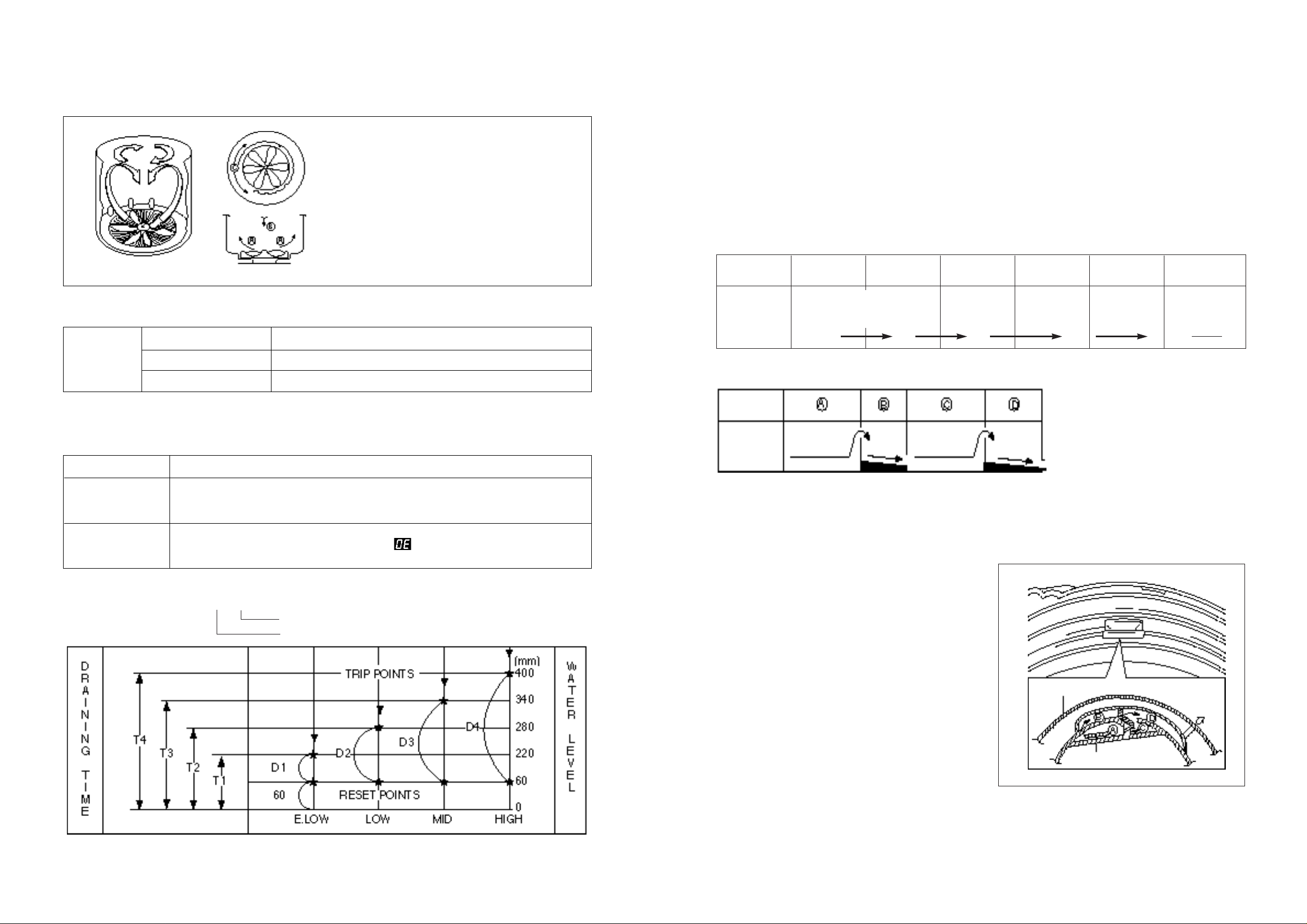
SOFTENER DISPENSER
This is the device to dispense the softener automatically by centrifugal force.
This is installed inside the auto-balancer.
FUNCTIONAL PRINCIPLE
1) Softener stays in room (A) when poured into softener inlet.
2) Softener moves from (A) to (B) by centrifugal force during intermittent spin process.
3) Softener flows from (B) to (C) during rinse process next to intermittent spin.
4) Softener moves from (C) to (D) by centrigfugal force during second intermittent spin.
After spin process is finished, the softener is added into the tub through softener outlet.
FLOW OF THE SOFTENER
FLOW OF THE SOFTENER INSIDE OF THE BALANCER
NOTE : Softener moves into the next room when r.p.m of the tub is more than 100 r.p.m.
HOW TO CHECK MOVEMENT
Pour a reasonable amount of “MILK” into softener
dispenser and operate the washer with no load. In
final rinse cycle, make sure that the milk is added into
the tub through softener outler.
PULSATOR SYSTEM
When the new shaped pulsator is retated C.W or C.C.W at a high speed, it makes the ‘heart-shaped’
waater currents as shown below.
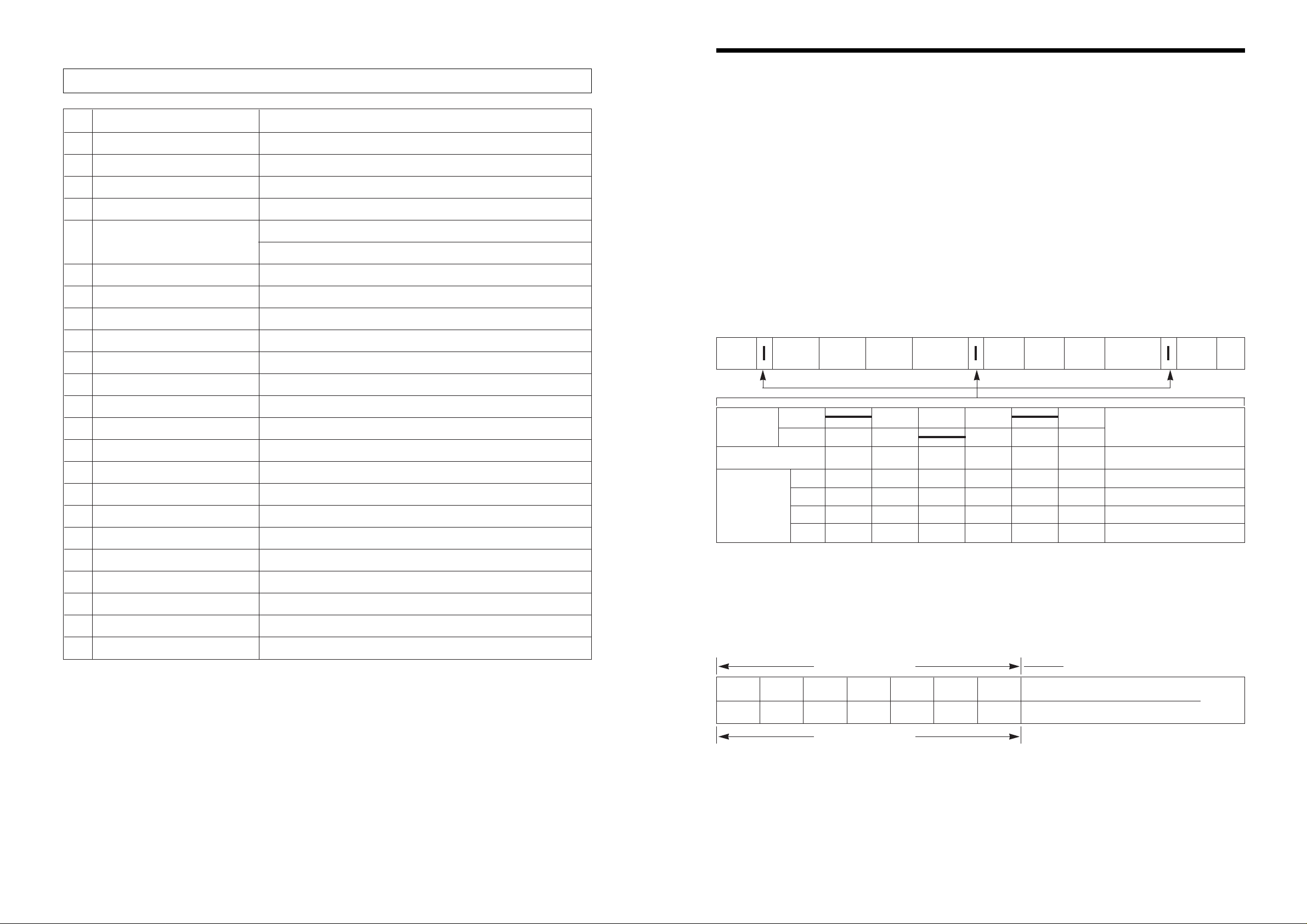
AUTOMATIC DRAINING TIME ADJUSTMENT
This system adjusts the draining time automatically according to the draining condition.
FUNCTIONAL PRINCIPLE
1) The micom can remember the time from the begining of drain to reset point when the pressure switch
reaches to “OFF” point
2) In case of continuous draining, residual drain time is determined by micom.
Draining time as a whole = D + 60
Residual drain time.
The time remembered by micom.
T1=D1+60 (Sec.) T2=D2+60(Sec.) T=D3+60(Sec.) T4=D4+60(Sec.)
W ATER CURRENTS
A Water is pushed up near the tub
wall by rotation of the pulsator.
B Water is pulled down in the
middle of the tub by rotation of
the pulsator.
C Water currents is generated by
rotation of the pulsator.
Draining
Good draining The washer begins spin process after drainage.
condition
Bad draining Draininig time is prolonged.
No draining Program is stopped and gives the alarm.
Drain Time Movement of the Program
Less than
Continue draining
4 minutes
More than
Program stops and gives the alarm with blinked on display lamp.
4 minutes
Wash Intermittent Hold Intermittent Rinse Spin
Spin Spin
Normal Centrifugal Flow in Centrifugal Flow in
force force force
Course (A) (B) (C) (D)
Room inside
the balancer
Centrifugal
force Flowing
by weight
Balancer
Softener
outlet
Softener inlet
6 7
AUTOMATIC UNBALANCE ADJUSTMENT
This system is to prevent abnormal vibration during intermittent spin and spin process.
FUNCTIONAL PRINCIPLE
1) Always the safety switch contact is “ON”
position.
2) In case that wash loads get uneven
during spin, the outer tub hits the safety
switch due to the serious vibration, and
the spin process is interrupted.
3) In case that P.C.B. ASS’Y gets “OFF”
signal from the safety switch, spin
process are stopped and rinse process
is started automatically by P.C.B.
ASS’Y.
4) If the safety switch is operated due to
the unbalance of the tub, the program is
stopped and the alarm is given.
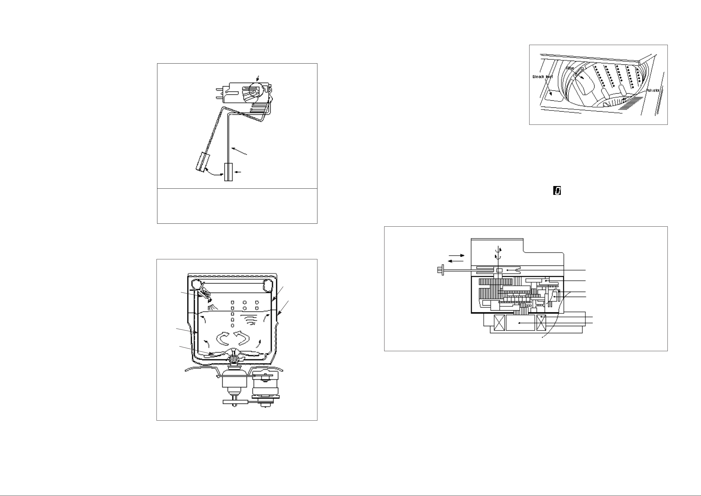
CIRCULATING-WATER COURSE AND LINT FIL TER
CIRCULA TING-WATER
The washing and rinsing effects have
been improved by adopting the water
system in which water in the tub is
circulated in a designed pattern.
When the pulsator rotates during the
washing or rinsing process, the water
below the pulsator vanes creates a water
currents as shown in figure.
The water is then discharged from the
upper part of the tub through the water
channel. About 40 L/min. water is
circulated at the ‘high’ water level,
standard wash load and standard water
currents.
LINT FILTER
Much lint may be obtained according to the kind of
clothes to be washed and some of the lint may also
sticks to the clothes.
To minimize this possibility a lint filter is provided on
the upper part of the tub to filter the wash water as it
is discharged from the water channel. It is good to
use the lint filter during washing.
HOW TO REPLACE LINT FILTER
1) Pull the filter frame upward.
2) Turn the lint filter inside out, and wash the lint off with water.
3) Return the filter as it was, and fix the filter frame to the slot.
RESIDUAL TIME DISPLAY
When the START/HOLD button is pressed, the residual time (min.) is displayed on the time indicator, and
it will be counted down according to process.
When operation is finished, the TIME INDICATOR will light up .
DRAIN MOTOR
STRUCTURE
FUNCTIONAL PRINCIPLE
1) When the DRAIN MOTOR connected to the power source(A.C 220V), the DRAIN MOTOR ratates with
900 r.p.m and revolves the pully by gear assembly for reducing.
2) When the pully is rotated, the pully winds the wire to open the drain valve.
3) Therefore, rotation of pulley changed to the linear moving of wire.
4) The wire pulls the brake lever of Gear Mechanism Ass’y within 5 seconds.
5) After the wire pulled, gear assembly is separated from motor and condition of pulling is held operation
of the lever.
6) When the power is turned off, the drain valve is closed because the wire returns to original position.
NOTE:
The alarm finished when you close the lid after opening
it. Check the unbalance of the wash load and the
installation condition.
Contact of safety switch
Contact lever A
Normal (ON)
Position of
unbalanced load
(OFF)
Pull
Loosen
Pully
Lever
Inductive ring
Magnet
Coil of motor
Magnet of motor
Tub
Filter
Water
channel
Pulsator
Outer tub
9
GEAR EMCHANISM ASS’Y
The proper water currents is made by the rotation of pulsator at a low speed (about 145 r.p.m) to prevent
the damage to the small sized clothes.
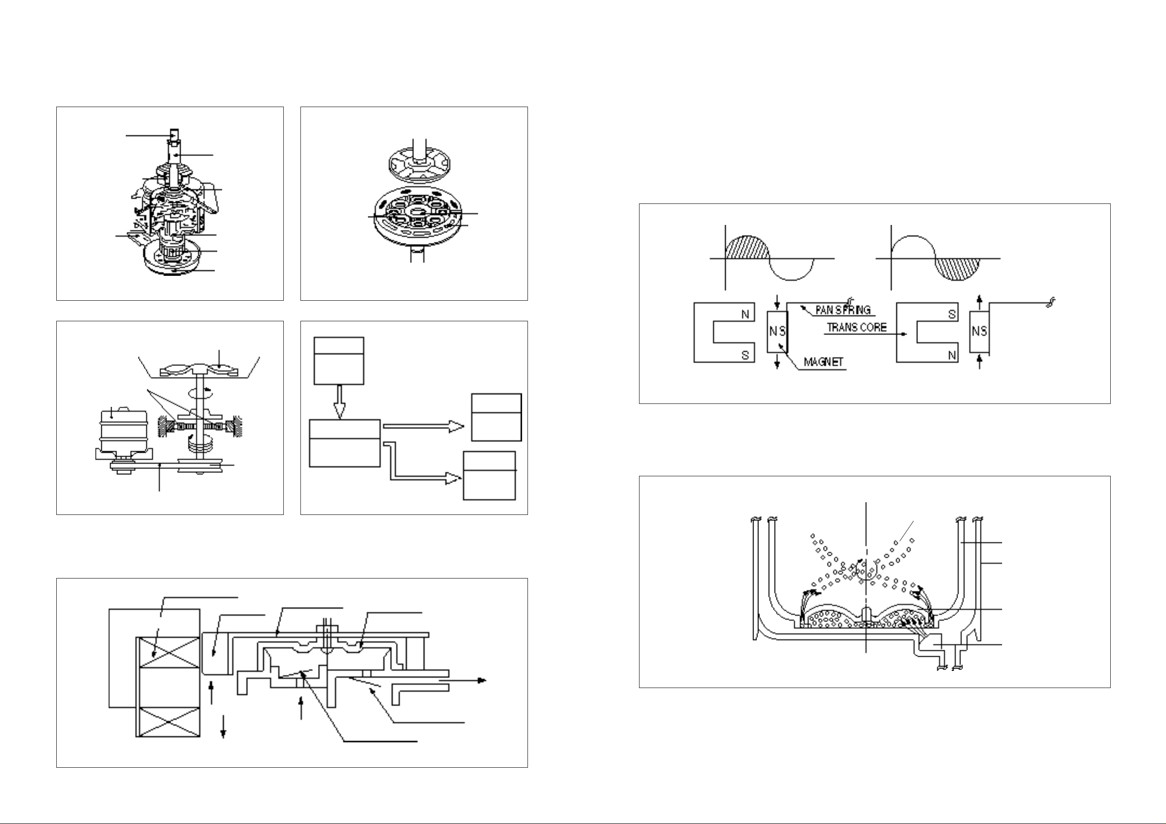
PRINCIPLE OF BUBBLE GENERA T OR
STRUCTURE
PRINCIPLE OF INTAKE & OUTLET OF THE AIR
INT AKE : ARMATURE moves up, and BELLOWS inhales the air. At the same time, protectro B is open
and A is close.
OUTLET : ARMATURE moves down, and BELLOWS exhausts the air. At the same time, protector B is
close and A is opend.
FUNCTIONS PRINCIPLE OF TRANS & MAGNET
• The phase of A.C electric power changes to 60 cycle/second.
• The magnetic pole of trans core is changed by the change of the phase of A.C electric power.
• The core repeats push and pull (3600 times/min.) of the at mature magnet.
FUNCTIONAL PRINCIPLE OF BUBBLE WASHING MACHINE
ACROSS SECTION
FUNCTIONAL PRINCIPLE
Bubble generator supplies the air from the bottom of outer tub to the inner space of pulsator, the air is
dispersed by the rotation of pulsator. Air-bubble is created by the centrifugal force, and rises up.
Pulsator shaft
Inner clutch spring
Brake lever
Spinner shaft
Planetary gear
Clutch spring
Clutch boss
Spinner pulley
Planetary gear
Sun gear
Internal gear
Pulsator
1 revolution
5.2 revolution
Spinner
pulley
V-belt
Planetary gear
Motor
Motor
1490 r.p.m
(50Hz)
Planetary Gear
1/5.2
Directly
Tub
750 r.p.m
Pulsator
130 r.p.m
Spinner Pulley
750 r.p.m
Bobbin & coil
Magnet
Armature
Bellows
Air out hole
Protector A
Protector B
Air in hole
Air
Air
Trans core
A.C A.C
Air bubble
Tub
Outer tub
Pulsator
Nozzle
10 11
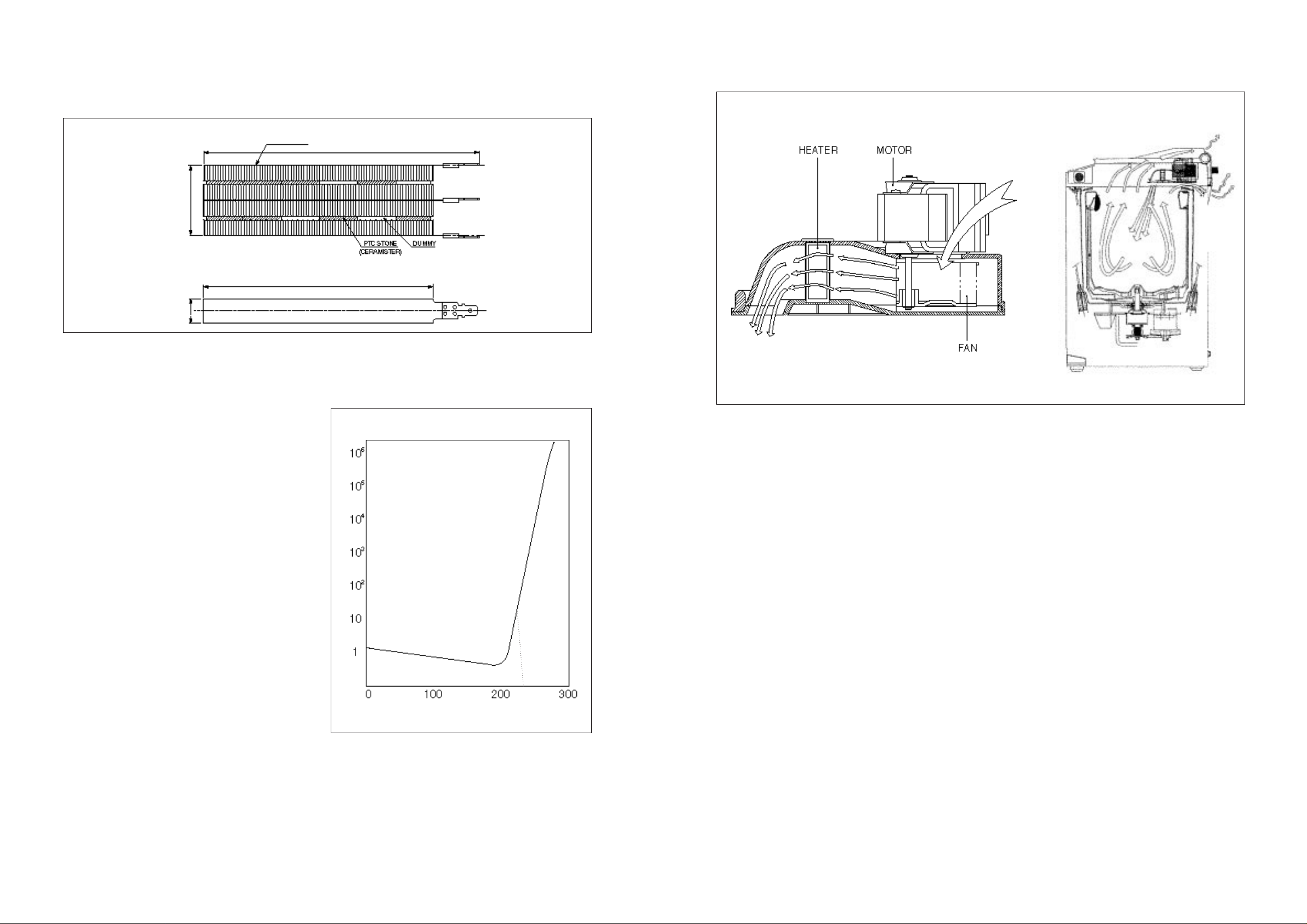
HEATER ASS’Y
HEA TER
FUNCTIONAL PRINCIPLE
• The heater is named the PTC (Positive Temperature coefficient) heater, it is automaticaly controlled
the heating value by changing of the air flow
and temperature through the element.
• If the surface temperature of the PTC heater
exceed to Tc point, the resistance of the heater
increases rapidly, so it stops a rise in
temperature.
• The heating value increase in proportion to the
volume of the air flow through the heater, so it
is kept the certain temperature.
• At state of the certain volume of air flow, through
the heater, the same heating value will
generate even if the ambient temperature is
changed.
STRUCTURE
PLA TE : t=0.5
FIN : t=0.22~0.3
171
±2.0
146
±1.0
44
±1.0
15
±0.5
- 0
ambient temperature
Resistance
Tc
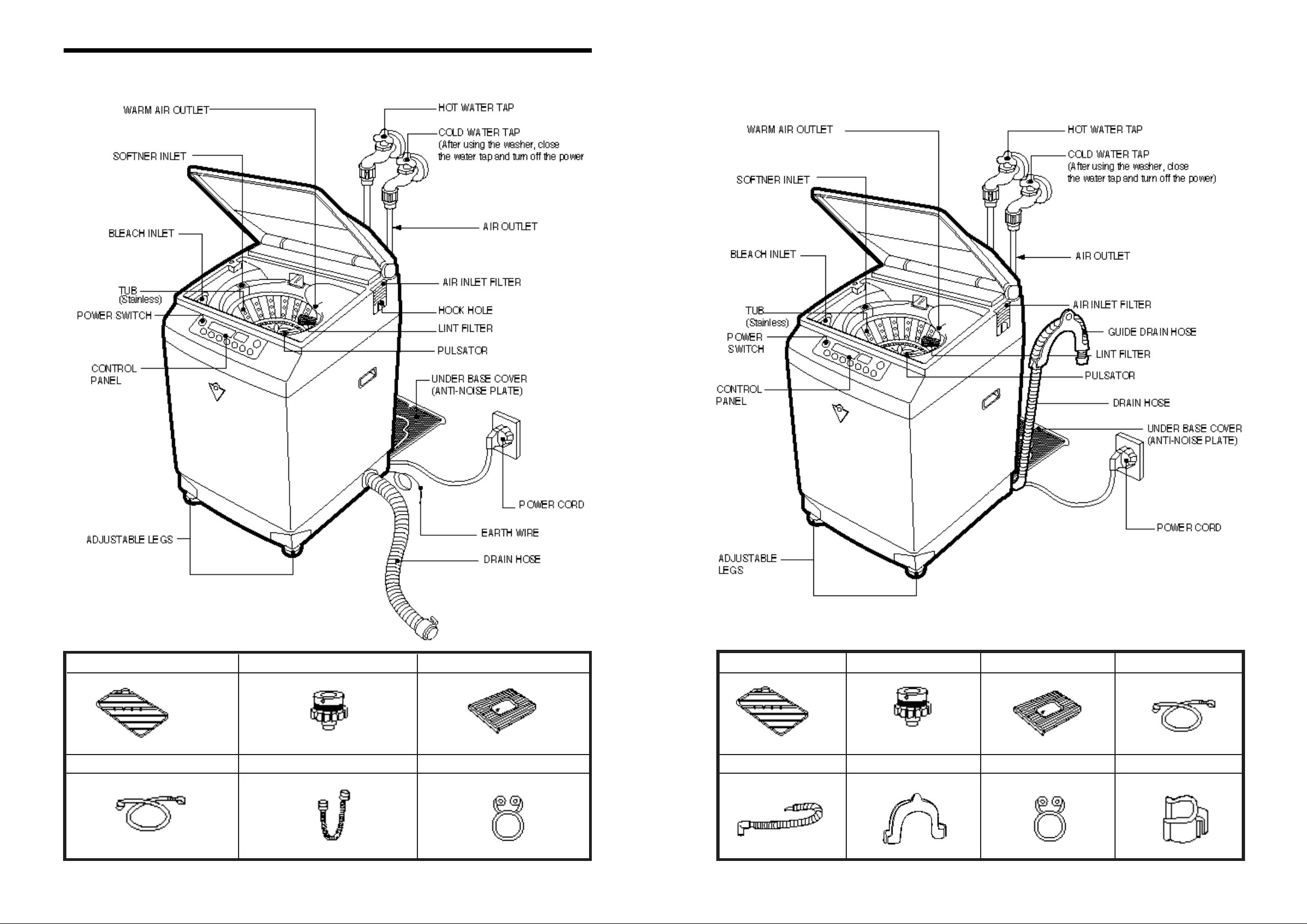
3. STRUCTURE OF THE W ASHING MACHINE
WATER TAP ADAPTER(2PCS)
UNDER BASE COVER
BASKET
INLET HOSE(2 PCS)
HOSE DRAIN
HOSE DRAIN CLAMP
ACCESSORIES
Drying Rack
Drain Hose
Water Tap Adapter(2Pcs)
In case of screw-shaped inlet hose,
water tap adapters will not be provided
Guide Drain Hose
Under Base Cover
Hose Clamp
Inlet Hose (2 Pcs)
Hose Fixture
ACCESSORIES
DWF-1095xE Model DWF-1095Px Model
14
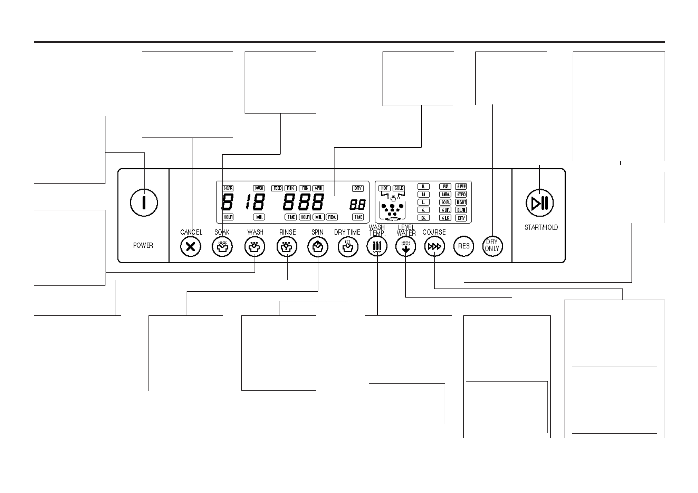
Button for Program Cancel
• It can be used to cancel the
full-automatic course.
• When the button is pressed
the display will be light down.
If you want to wash, rinse or
spin, you can press one of
the button.
• It can be used to adjust the
pulsator rotate in dry course.
Soak Time Selector
• It can be used to
adjust soak time.
• As the button is
pressed, you’ll see
repeated.
1
➜2➜3➜4 signs
How to Use Switch
Press this switch to
turn the power ON or
OFF.
After turning OFF the
power, wait for more
than 3 seconds and
then turn it ON again.
Washing TIme Selector
• It can be used to
adjust washing time
• As the button is
pressed, you’ll see
the repeated
2➜4➜6➜8➜10➜12
➜14➜16➜18 signs
Rinse Time Selector
• This button selects the
number of times you want
to rinse.
• As the button is pressed, it
will be repeated 1 time
rinse➜1 time feed➜2 times
rinse➜2 times feed➜3
times rinse➜3 times
feed➜4 times rinse➜4
times feed ➜5 times rinse
➜5 times feed
RINS : Normal Rinse
FEED : Feed Rinse
Spin Time Selector
• It can be used to
change spin time.
• As the button is
pressed, it will be
repeated
1➜2➜3➜4➜5➜6➜7
➜8➜9 signs.
Dry Time Selector
• It can be used to
adjust dry time.
• As the button is
pressed, it will be
repeated
0.5➜1➜1.5➜2➜2.5➜
3 signs.
4. FUNCTION OF THE CONTROL PANEL
Time Display
• The lamps easily
indicate the option
selection of washing
program and process
by letters.
Exclusive Dry Button
• It can be used to dry
exclusively.
Start/Hold Button
• Operation and temporary
stop are repeated as it is
pressed it will be repeated
‘Operation’, ‘Temporary stop’
according to the one time
pressing or two times
pressing.
When you want to change
course in operating ;
- Press the S/H button.
- Select the course that you
want to change.
- Press the S/H button again!
Wash Time
• It can be used to
pre-engage time for
wash.
Water Temperature Selector
• It can be used to choose
water temperature to be
supplied.
• As the button is pressed, it
will be repeated following
signs ;
COLD➜HOT+COLD➜HOT
TEMP. : TEMPERA TURE
HOT : HOT W ATER
HOT+COLD
: WARM W ATER
COLD : COLD WATER
Water Level Selector
• It can be used to adjust
amount of water according
to the size of the load to be
washed.
• As the button is pressed.
Water level is selected by
H➜M➜L➜S➜E.S
LEVEL. : WATER LEVEL
H. : HIGH LEVEL
M. : MIDDLE LEVEL
L. : LOW LEVEL
S. : SMALL LOW LEVEL
E.S. : EXTRA SMALL LEVEL
Course Selector
• It can be used to select the fullautomatic course.
• As the button is pressed, it will
be selected following order:
MEM.➜SOAK➜ SUIT➜SILK➜ SPEE➜
STRO➜NIGHT➜ BLAN➜DRY➜ FUZ.
MEM : MEMORY
SOAK : SOAK
SUIT : SUIT
SILK : SILK
SPEE : SPEEDY
STRO : STRONG
NIGHT : NIGHT
BLAN : BLANKET
DRY : DRY
FUZ. : FUZZY
15 16
5. DIRECTIONS FOR INSTALLA TION AND USE
HOW TO INSTALL THE WASHING MACHINE
SELECTION OF THE INSTALLING PLACE
Install the washing machine on a horizontal solid floor.
If the washing machine is installed on an unsuitable
floor, it could make considerable noise and vibration.
•
The proper installation of the washing machine
can increase the wash effectiveness and the
life of it.
INST ALLATION OF THE UNDER BASE COVER
HOW TO INSTALL ON A INCLINED PLACE
Avoild installing it in these places.
•
A place where it would be exposed to direct
sunlight.
•
A place where there is a heater or heat
appliances.
•
A place where it would be supposed to be
frozen in winter.
•
A place with cola gas and a damp place like a
1 Separate under base
cover from the unit.
2 There is a inserting
place under of the
back side on the
washer.
3 Let the base cover
that can be shown the
“UP” sign.
4 Insert the base cover
into the slot of under
base until come to the
end of the slot.
11
Height Setting
•
After controlling the height by
turning the adjustable legs with the
washing machine inclined a little,
tighten the outer cap to be locked
with the washer put down to the
ground.
22
Check the Horizontal
Status
•
Check the position of tub above the
center of the washer.
After installing the washing machine, close the under-base
cover.
If the washing machine is installed on an unsuitable floor, it could make
consider-able noise and vibration, and could cause a malfunction. Use
the height rebber to adjust the washing machine so that is sits properly.
NOTES :
The openings must not be
obstructed carpeting when the
washing machine is installed on
a carpeted floor.
Lock
Loose
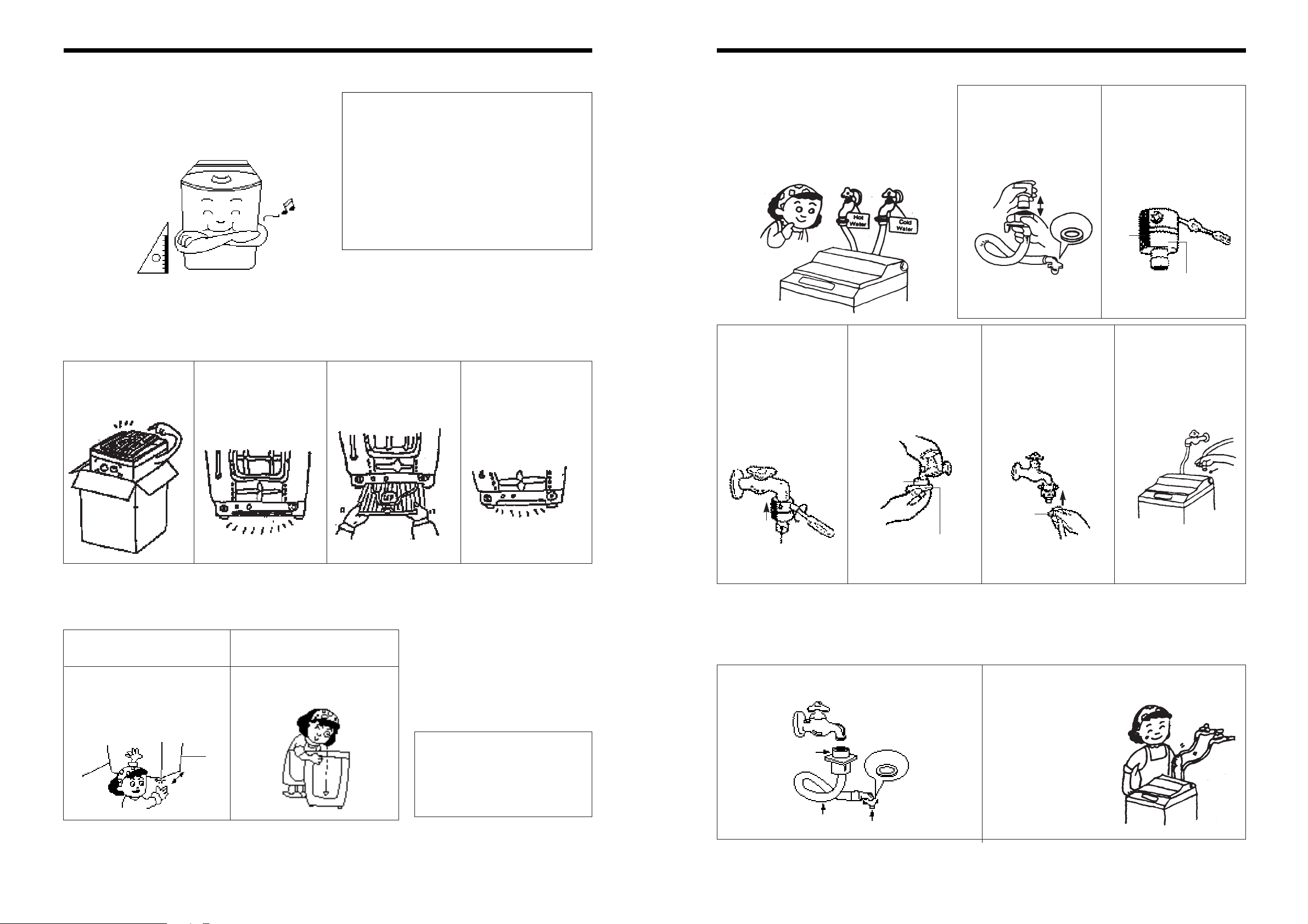
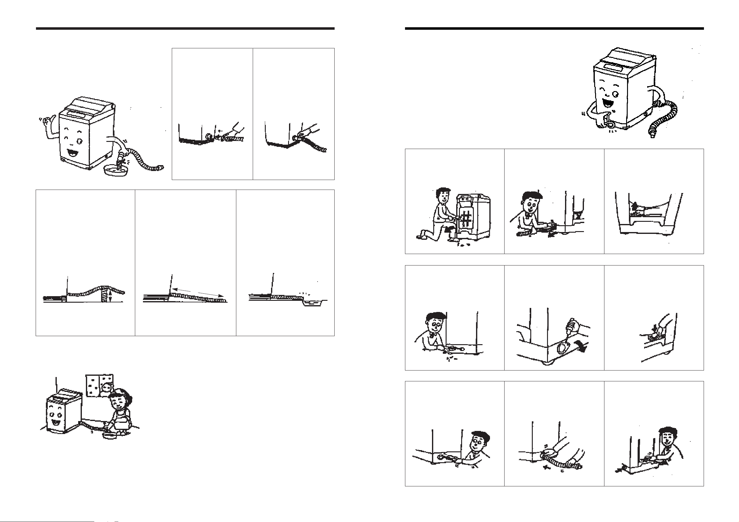
HOW TO CONNECT THE INLET HOSE
IN INST ALLING THE INLET HOSE
Be careful not to mistake in supplying
between the hot (maximum : 50˚C) and
cold water.
In using only one water tap, connect the
inlet hose tot the cold water inlet.
• FOR SCREW-SHAPED TAP
1
Pull down the collar of
the inlet hose to
separate it from the
water tap adapter.
2
Loosen the four screws
at the water tap
adapter, but don’t
loosen the screw until
they are separated
from the water tap
adapter.
1
Connect the inlet hose to the water tap by
screwing the connector D tightly.
2
Connect the connector C of the inlet hose to the
water inlet of the washing machine by turning it
clockwise to fix it tightly.
• Please check the rubber
packing inside
the connector C
of the inlet hose.
3
Connect the water
tap adapter to the
water tap, and
tighten the four
screws evenly while
pushing up the
adapter so that the
rubber packing can
stick to the water
tap tightly.
4
Remove the tape,
and screw
connector B into
connector A tightly.
5
Connect the inlet
hose to the water
tap adapter by
pulling down the
collar of the hose
end.
6
Connect the inlet
hose adapter C of
the inlet hose to the
water inlet of the
washer by turning it
clockwise to be
fixed tightly.
•
Please check the
rubber packing inside
the inlet hose adapter
of the hose.
Water Tap
Adapter
Collar
➜
➜
Connector C
Rubber
packing
Connector D
Connector C
Inlet Hose
Rubber
Packing
Tape
Water Tap Adapter
Water Tap Adapter
Connector B
Collar
Connector A
1
2
17 18
HOW TO REROUTE THE DRAIN HOSE (ONLY xE MODEL)
1
Loosen the back cover
screws on the rear side of
the washer, and detach the
back cover.
2
Detach the outside drain
hose with widening hose
clamp.
3
Detach the fixing band by
hand.
4
Detach the inside drain
hose fixing screw with
O
±
driver.
5
Detach the drain hole
cover of the hoping
direction.
6
Move the drain hose to the
direction to be changed,
and attach the fixing band.
7
Insert the inside drain
hose, and the fasten the
fixing screw tightly.
8
Insert the outside drain
hose together with the
hose-fixing clamp.
9
Attach the detached back
cover again, and insert the
detached drain-hole-cover
instead of the original one.
HOW TO USE THE DRAIN HOSE(ONLY xE MODEL)
INST ALLING DRAIN HOSE
Widen the drain clip and insert the drain
hose into the drain tap together with drain
hose. Dipping the end of the drain hose in
warm water makes easy to insert the drain
hose.
HOW TO USE IN WINTER
1
Insert the drain hose
into the drain tap.
2
Secure the hose clip
around the end of the
drain hose.
• In case that it goes over a doorsil
water flow will be restricted if any
portion of the drain hose is
raised more than 20 cm from the
ground.
• In case that it is connected when
the drain hose is extended, it
may not exceed 3 meters.
• Take care the end of the drain
hose. Do not sink the end of the
drain hose.
•
To avoid the washing machine’s being frozen.
- Remove the inside water of the washing machine completely.
- Remove the inside water of the inlet-hose and drain hose completely.
•
In case of being frozen.
- Dip the detached inlet-hose in the hot water (about 50°C) (* Don’t use
above 50°C surely)
- Leave the tub alone for 10 minutes with poruing the hot water. (about
50 °C)
- Check the drain and inlet’s operation after attaching the inlet-hose.
20cm
3m
19 20
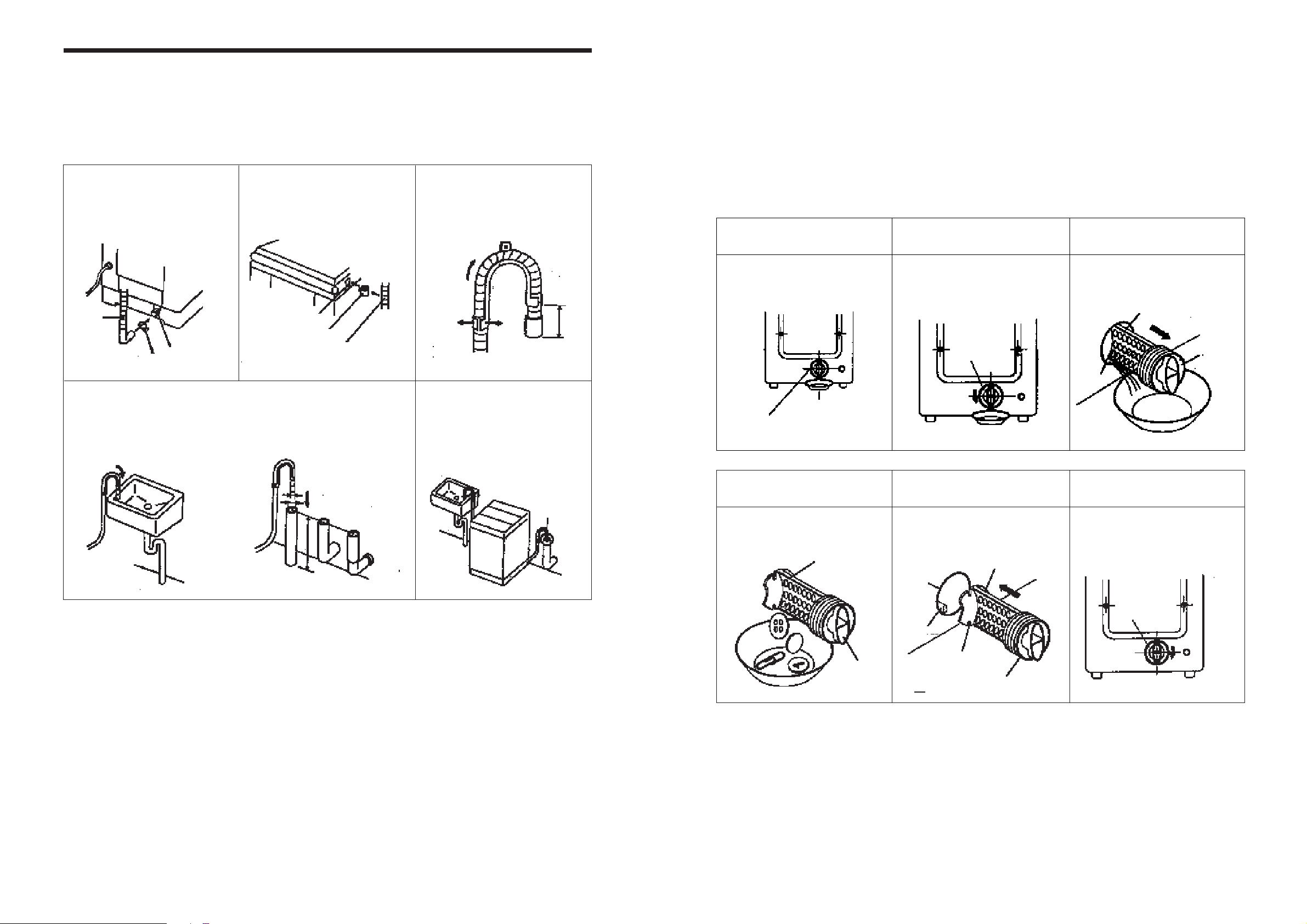
HOW TO CLEAN DRAIN FILTER (ONLY Px MODEL)
In this washer, the drain filter is equipped at the back side of it.
This drain filter is to screen the foreign stuffs such as threads, coins, pins, buttons etc...
And this should be cleaned frequently(every 5 times of use) for its smooth operation.
Drain problem could be caused if the drain filter is not cleaned at proper time.
Please Keep it clean.
Incase you clean the drain filter, please follow the instructions as below.
NOTES
During the operation, the “OE” signal means drain error can displayed on the control panel.
In this case, the main cause of that problem is the blocking of the drain filter.
If you clean the drain filter following above instructions, you could continue the normal operation of this
washing machine to rest the program please turn the power off and on again.
11
Remove the remained
water
• Put down the remained water in the
hose. And put a container under the
filter to collect water.
22
Unscrew the cap.
• Turn the cap counter clockwise.
33
Release the filter
assembly.
• Pull out the filter assembly off the case
of the main body.
44
Remove the foreign
stuffs.
•
Clean the drain filter removing the
foreign stuffs.
55
Put the filter assembly
back.
• Put the filter along the guiding
prominence of the case. Please note
the left position of the filter adjusting
the groove to the guide rib.
66
Lock the cap.
• Turn the cap clockwise tightly.
CONTAINER
FITER
CAP
FILTER
CAP
CASE
CAP
CAP
SLIT
GUIDE RIB
CASE
FILTER
CAP
FILTER
HOW TO INSTALL THE DRAIN HOSE (ONLY Px MODEL)
INST ALLATION OF THE DRAIN HOSE
Never forget to install drain hose before operating this washing machine.
There are a drain hose, a hose clamp, a hose fixture and a hose guide in the washing machine.
NOTES
1. Keep the drain hose fixed tightly in the hose fixture, or let the highst point of the drain hose be more
than 1m above the floor.
If not so, the water in the washing machine could be drained during operation.
2. Be sure that the height of the drain hose must be less than 1.5m above the floor.
If not so, the water in the washing machine could not drain.
3. The hose guide MUST be fitted to the drain hose. The drain hose sould not extend more than 55mm
from the end of the hose guide. This is to prevent ‘SYPHONING’.
If necessary the drain hose can be trimmed to length.
1
Connect the drain hose to
the drain outlet at the back
side of the washing
machine, and fasten it
tightly with the clamp
supplied.
4
Hook the drain hose to the
edge of the tub, paying
attention that there are no
bends or constractions
along the drain hose.
2
Insert the hose fixture into
hook hole at the side of the
body , and fix the drain
hose by inserting it into the
hose fixture.
Or, connect the drain hose to a
standpipe of a diameter greater
than that of the drain hose and at a
height of min. 70cm.
3
Attach the hose guide,
included in the accwssory
kit, to guide the drain hose
over the tub or standpipe.
5
Position the washing
machine next to the wall.
Drain
hose
Drain outlet
Hook Hole
Hose Fixture
Drain Hose
Pull Hose
through
Flex Hose
Guide
apart
MUST be
ventilated
55 max.
70cm min
Hose Clamp
21 22
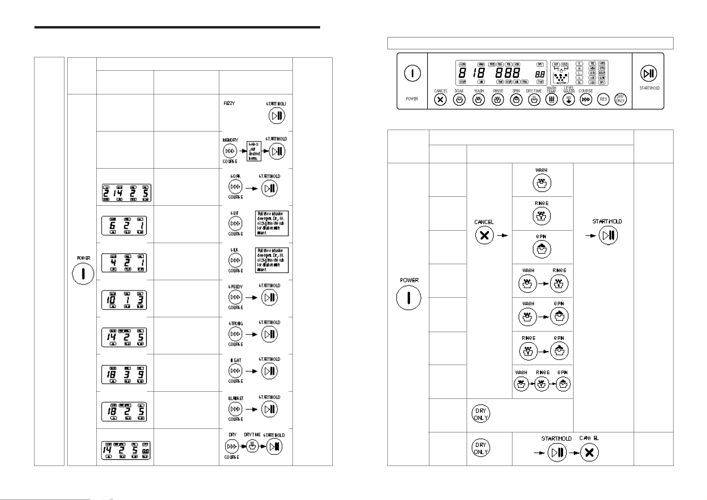
33
Procedure of Washing (Washing machine does it automatically).
PARTIAL SELECTIONS AMONG WASH, RINSE, SPIN AND DRY
Only Wash
Only Rinse
Only Spin
Wash & Rinse
Wash & Spin
Rinse & Spin
Wash➜Rinse
➜Spin
Only Dry
Only Dry
(by the drying
rack)
Cancel the set
program with
pressing the
button.
• In case of canceling
the program while
the washer
operates.
Press the
“Start/Hold” button
first and then
“Cancel”one
Set the dry
time by
pressing
“DRY
ONL Y”
Press the “S/H”
button
If once more pressed the
washer will be stopped.
For keeping operation
continuously to the set
program, press another time.
Set the dry time by pressing
“DRY ONLY” button.
Dry time is changed from 30 min. to 3 hr
by pressing the “DRY ONLY” button one
step in 30 min.
End of
washing
informed by
buzzer.
After 10 minutes
later from the end
of the washing the
power switch will
be turned off
automatically
Press the
“CANCEL” button
to stop pulsator
rotate while using
the drying rack
22
Selecting Course
11
Pressing
the Power
Switch
Washing
Procedure
Procedure to Press the Button
6. PROCEDURE OF FULL-AUTOMATIC W ASHING
22
Selecting Course
Selecting Course Kinds of the Laundry
Prepare
for
washing.
Pressing
the power
switch
Put the
clothes
wash in.
Select
the
washing
course.
This selection is for general
washing.
This selection is washing course
by your desire. (The memory
items are washing time, rinsing
times, spin time, water level,
water temperature)
This course is used to increase
the wash effect by keeping the
clothes soaked suffciently in the
wash water.
This selection is effective for
delicate clothes
• Just follow the washing procedure.
• 1.5 kg limitation for one-time-wash.
This selection is effective for
some clothes made of silk.
• Do not put in the wash marked with
dry-cleaning.
• 1 kg’s limitation for one-time-wash.
This selection effective for
washing light or less dirty wash.
The selection is effective for
blue-jean, climbing clothes,
ruck-sack, sports wear, etc...
This selection is for a nightwashing housewife who has no
opportunity at day time.
This selection is effective for
blanket, curtain, carpet, etc...
•4 kg’s limitation for one-time-wash.
This selection is effective for
subsequent drying to washing.
• 3 kg’s limitation for one-time-wash.
Procedure to
press the Button
FUZZY
(SENSOR)
MEMORY
(USE ONLY FUZZY
COURSE)
SOAK
SUIT
SILK
SPEEDY
STRONG
NIGHT
BLANKET
WASHING & DRYING
11
Pressing
the
Power
Switch
The washing
program is
processed by
your desired
items.
➜
➜ ➜
 Loading...