

Page 1

WASHING MACHINE
CCoonntteennttss
1. SPECIFICA TIONS................................................................................................................... 2
2. STRUCTURE OF THE WASHING MACHINE....................................................................... 3
3. DIRECTIONS FOR INST ALLATION AND USE
INSTALLATION OF THE UNDER BASE COVER.......................................................................... 4
HOW TO INSTALL ON AN INCLINED PLACE .............................................................................. 4
HOW TO CONNECT THE INLET HOSE........................................................................................ 5
HOW TO CLEAN THE FILTER....................................................................................................... 6
4. FEA TURE AND TECHNICAL EXPLANATION
FEATURE OF THE WASHING MACHINE ..................................................................................... 7
WATER CURRENT TO ADJUST THE UNBALANCED LOAD...................................................... 7
FUNCTION FOR SOAK WASH...................................................................................................... 7
AUTOMATIC WATER SUPPLY SYSTEM FOR BLANKET WASH................................................ 7
PULSATOR SYSTEM ..................................................................................................................... 8
AUTOMATIC DRAINING TIME ADJUSTMENT ............................................................................. 8
AUTOMATIC UNBALANCE ADJUSTMENT .................................................................................. 9
CIRCULA TING-WATER COURSE AND LINT FILTER .................................................................. 9
LINT FILTER.................................................................................................................................. 10
RESIDUAL TIME DISPLAY.......................................................................................................... ..10
DRAIN MOTOR............................................................................................................................. 10
GEAR MECHANISM ASS’Y...........................................................................................................11
5. DIRECTIONS FOR DISASSEMBLY AND ADJUSTMENT
GEAR MECHANISM ASS’Y REPLACEMENT..............................................................................12
MOTOR SYNCRONOUS AND VALVE REPLACEMENT.............................................................14
6. THE REP AIR METHOD OF GEAR MECHANISM FOR CLUTCH SPRING PROBLEM
THE STRUCTURE OF GEAR MECHANISM................................................................................15
HOW TO CHECK THE CLUTCH SPRING PROBLEM.................................................................16
THE PROCESS OF DISASSEMBLE.............................................................................................17
THE PROCESS OF ASSEMBLE...................................................................................................19
REPLACE THE CASE FIL TER ASS’Y..........................................................................................21
7. TECHNICAL POINT
VALVE DRAIN ASS’Y AND GEAR MECHANISM........................................................................ 22
REPLACING PROCESS OF SYNCHRONOUS MOTOR WIRE................................................. 22
PULLEY MOTOR ASS’Y............................................................................................................... 23
SWITCH SAFETY ASS’Y...............................................................................................................24
SENSOR PRESSURE ASS’Y........................................................................................................24
8. TROUBLE SHOOTING GUIDE
CONCERNING WATER SUPPLY..................................................................................................25
CONCERNING WASHING........................................................................................................... 26
CONCERNING DRAINING........................................................................................................... 27
CONCERNING SPINNING........................................................................................................... 28
CONCERNING OPERA TION....................................................................................................... 29
9. PRESENT ATION OF THE P.C.B ASS’Y.............................................................................. 30
APPENDIX
WIRING DIAGRAM....................................................................................................................... 31
PARTS DIAGRAM......................................................................................................................... 37
PARTS LIST ..................................................................................................................................41
CIRCUIT DIAGRAM...................................................................................................................... 48
Page 2
1. SPECIFICATIONS
2
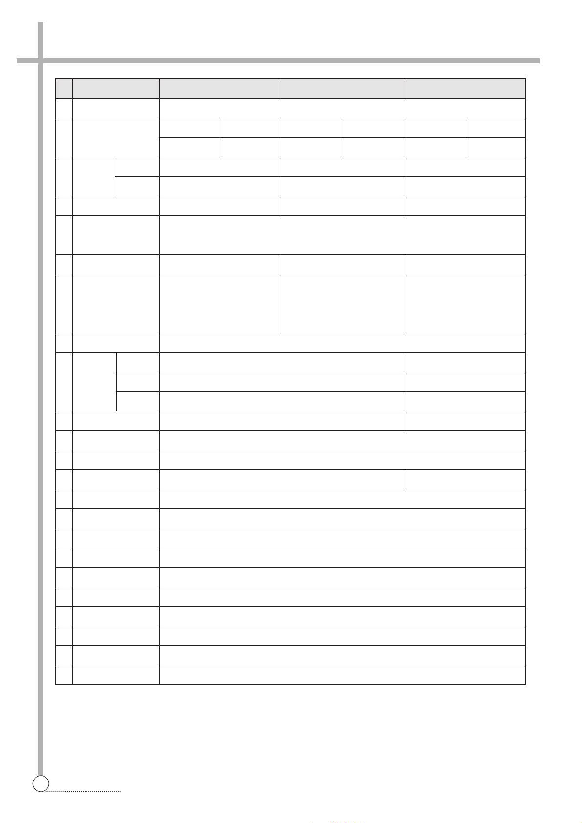
SPECIFICATIONS
NO. ITEM DWF-7094 DWF-8094 DWF-1094
1 POWER SOURCE AVAILABLE IN ALL LOCAL AC VOL TAGE AND CYCLE
2
POWER CONSUMPTION
3
MACHINE NON-PUMP
WEIGHT PUMP
4 DIMENSION (WXHXD)
5 WASHING COURSE
FULL AUTOMA TIC 6 COURSE
(FUZZY, MEMORY, BLANKET, SUIT, HEAVY, ECONOMY)
6
WATER CONSUMPTION
7
WATER LEVEL SELECTOR
8
OPERATING W ATER PRESSURE
0.3kgf/cm2~8kgf/cm
2
(2.94 N/cm2~78.4N/cm2)
60Hz
9 50Hz
SUIT COURSE
10 PULSAT OR 6 WINGS (Ø406mm)
11
WATER LEVEL CONTROL
ELECTRONICAL SENSOR
12 ANTI NOISE PLATE O
13
GEAR MECHANISM ASS’Y
HELICAL GEAR
14 LINT FILTER O
15 SOFTENER INLET O
16
FUNCTION FOR SOAK WASH
O
17 ALARM SIGNAL O
18
RESIDUAL TIME DISPLAY
O
19
AUTO. WATER SUPPLY
O
20 NEW WATER FLOW WATER FLOW FOR ADJUST THE UNBALANCED LOAD
21
FUNCTION FOR BUBBLE
O
22
AUTO RE-FEED WATER
O
23 AUTO POWER OFF O
50Hz
400W
60Hz
430W
50Hz
400W
60Hz
430W
50Hz
480W
60Hz
550W
42.5Kg (GROSS : 48Kg)
43.5Kg (GROSS : 49Kg)
610mm X 965mm X 655mm
44.5Kg (GROSS : 50Kg)
45.5Kg (GROSS : 51Kg)
610mm X 980mm X 655mm
49Kg (GROSS : 56Kg)
50Kg (GROSS : 57Kg)
630mm X 980mm X 670mm
NORMAL 190L
HIGH(68L), MEDIUM(57L)
LOW(46L), SMALL(35L)
E.SMALL(28L)
NORMAL 215L
HIGH(79L), MEDIUM(64L)
LOW(51L), SMALL(40L)
E.SMALL(31L)
NORMAL 250L
HIGH(93L),
¢‚(85L)
MEDIUM(77L), ¢‚(70L)
LOW(63L), ¢‚(50L)
E.SMALL(40L)
WASH : 1 15~125, SPIN : 740~760
WASH : 1 10~115, SPIN : 660~670
WASH : 60 (60Hz), 50 (50Hz)
6 WINGS (Ø376mm)
SPUR GEAR
WASH : 125~140, SPIN : 675~695
WASH : 120~130, SPIN : 630~640
WASH : 65 (60Hz), 55 (50Hz)
REVOLUTION
PER MINUTE
Page 3
2. STRUCTURE OF THE WASHING MACHINE
3
STRUCTURE
„‡
¿ł
¿„
ˆº …
…… ¯„
˙ –
¯» …
˜ ‰”
„¿´
¿ /
ˇ‰ˆ`⁄`
„
‡
`
œ
–
…
……`ƒ•fi „
¿´
DAEWOO AUTOMATIC WASHER
¿´ …
„
¿´…
‡ˆ …
……¯„ ¯»…
˙
–
¿„
‡†
”‰ˆ
£
‰ˆ
£
»
¿
¿
”—
– ·ª¿ ”„ ´ …
”‚†
18
14
10
7
9
5
3
61234»¿1
˘`
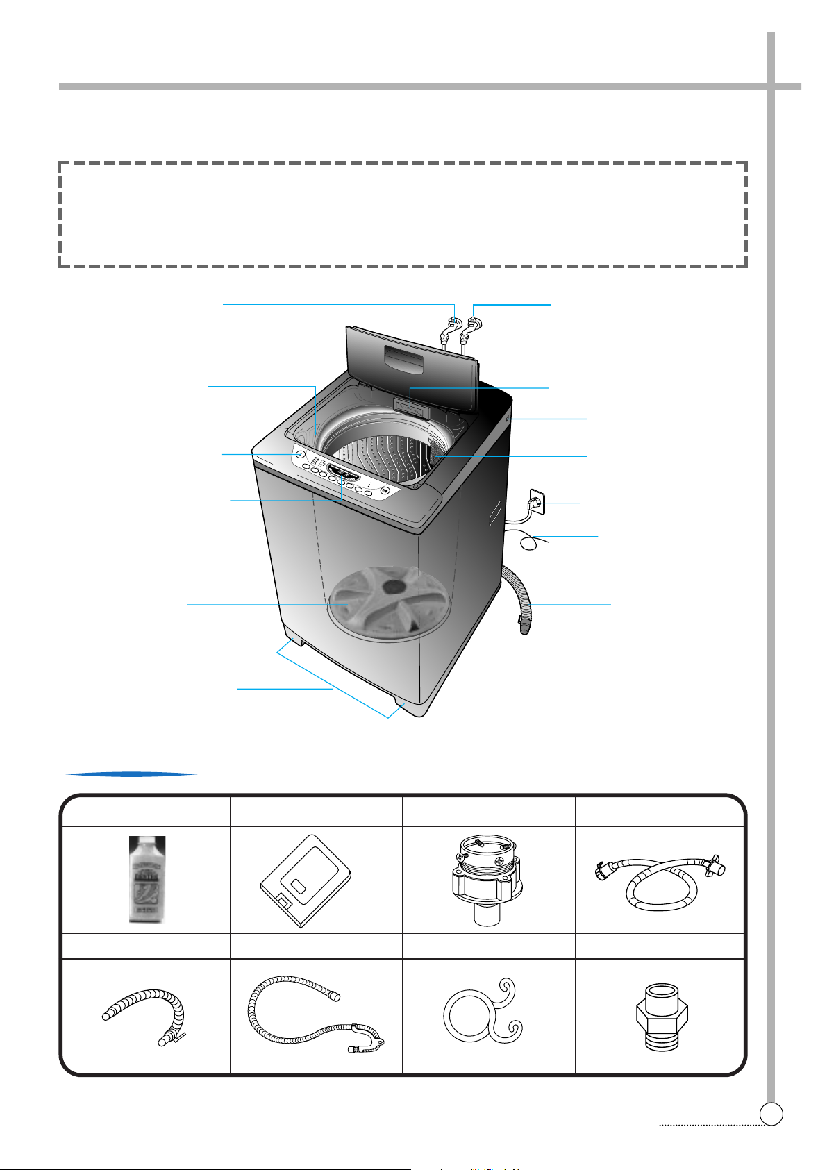
• BLEACH INLET
• HOT WATER TAP
• POWER SWITCH
• CONTROL PANEL
• PULSATOR
• ADJUSTABLE LEGS
• GROUND WIRE
In case of 3-wire power cord
ground wire will not be provided.
• COLD WATER TAP
After using the washer,
close the water tap
and turn off the power.
• POWER CORD
• DETERGENT CASE
• HOOK HOLE
• LINT FILTER
• HOSE DRAIN
After using the washer, close the water
tap and turn off the power. In case of
the single valve model, There is no
hot water valve.
DRYTEN
HOSE DRAIN O AS [NON-PUMP]
COVER UNDER [OPTION]
HOSE DRAIN O AS [PUMP]
WA TER TAP ADAPTER
HOSE DRAIN CLAMP
INLET HOSE
CONNECTOR INLET [OPTION]
Accessories
UP
The parts and features of your washer are illustrated on this page.
Be come familiar with all parts and features before using your washer.
NOTE
• The drawing in this book may vary from, your washer model. They are designed to show the different features of all models covered by this book, Your model may not include all features.
• Page references are included next to same features.
Refer to those pages for more information about the features.
Page 4
3. DIRECTIONS FOR INSTALLATION AND USE
4
DIRECTIONS
The openings must not
be obstructed by carpeting when the washing
machine is installed on a
carpeted floor.
§§
è
Installation Of The Under Base Cover [Option]
§§
è
How To Install On An Inclined Place
¡ The place where it would be exposed to
direct sunlight.
¡ The place nearby a heater or heat appli-
ance.
¡ The place where it would be supposed
to be frozen in winter.
¡ The kitchen with coal gas and a damp
place like a bathroom.
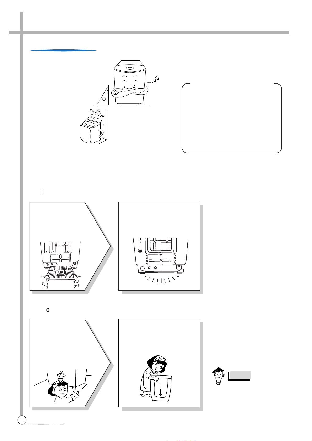
NOTES
Install the washer on a horizontal
solid floor. If the washer is installed
on an unsuitable floor, it could make
considerable noise and vibration.
Installing Place
NNeevveerr iinnssttaallll iinn tthheessee ppllaacceess
2
Push the noise insulation plate
into the end, which decrease
the noise made by this washer.
1
The packing box
opened, there is a
noise insulation plate
at the bottom of the back
(DWF-7094, 8094) or front
(DWF-1094).
2
Check the Horizon
Status
Check the position of tub above
the center of the washer.
1
Horizon
Setting
After controlling the height
by turning the adjustable
leg, let the washer put
down to the ground.
Keep the machine body
more than 25cm apart from
the wall surface. It will
make easy cleaning the
drain filter which is equipped
at the back side of it. And if
it comes into contract vibration may occur.
10Cm
Page 5
5
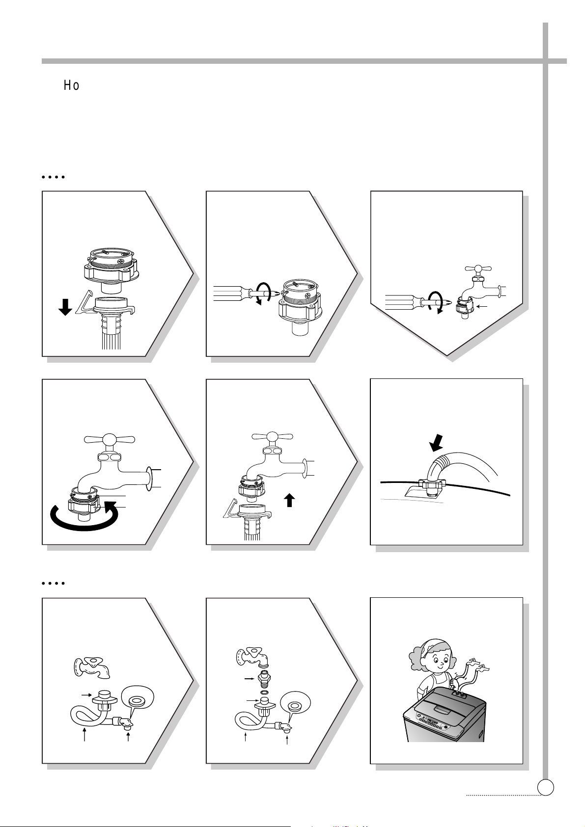
CONNECTION
FOR ORDINARY TAP
6
Connect the inlet hose adapter
of the hose to the water inlet of
the washer by turning it clockwise to be fixed tightly.
• Please check the rubber packing
inside the inlet hose adapter of
the hose.
1
Pull down the collar
of the inlet hose to
separate it from the
water tap adapter.
2
Loosen the four
screws at the water
tap adapter, but don’t
loosen the screws until
they are separated from
the water tap adapter.
4
Remove the tape,
and screw connector
B into connect A tightly.
5
Connect the inlet
hose to the water tap
adapter by puling down
the collar of the hose end.
3
Connect the water tap
adapter to the water tap tighten the four screws evenly
while pushing up the adapter
so that the rubber packing
can stick to the water tap
tightly.
§§
è
How to Connect the Inlet Hose
Be careful not to mistake in supplying between the hot(maximum : 50˚C) and cold water.
In using only one water tap or in case of attached one water inlet valve, connect the inlet hose to the cold water inlet
valve.
Do not over tighten : this could cause damage to couplings.
FOR SCREW-SHAPED T AP
3
Insert the inlet hose adapter
into the water inlet of a washer
and turn it to be fixed.
• Assert the packing in the inlet
1
Connect the inlet
hose to the water tap
by screwing the connector D tightly.
2
Connect the connector-inlet supplied if
necessary.
Inlet Hose
Connector D
Rubber
Packing
Connector C
Connector
Inlet
Rubber
Packing
Connector D
Connector C
Hose
„‡
¿ł
¿„
ˆº …
…… ¯„
˙ –
¯» …
˜ ‰”
„¿´
¿
/
ˇ‰ˆ`⁄`
„
‡
`
œ
–
…
…
…
`
ƒ
•
fi
„
¿
´
D
A
EW
O
O
A
U
T
O
M
A
T
I
C
W
A
S
HE
R
¿´ …
„
¿´…
‡ˆ …
…
…
¯
„
¯
»
…
˙
–
¿
„
‡
†
”
‰
ˆ
£
‰
ˆ
£
»
¿
¿
”
—
– ·
ª
¿ ”
„
´
…
”‚†
18
14
10
7
9
5
3
6 12 34 »¿ 1
˘
`
TAPE
Connector B
Connector A
§§
è
How to Connect the Inlet Hose
Be careful not to mistake in supplying between the hot(maximum : 50˚C) and cold water.
In using only one water tap or in case of attached one water inlet valve, connect the inlet hose to the cold water inlet
valve.
Do not over tighten : this could cause damage to couplings.
Page 6
6
CONVENIENCE
§§
è
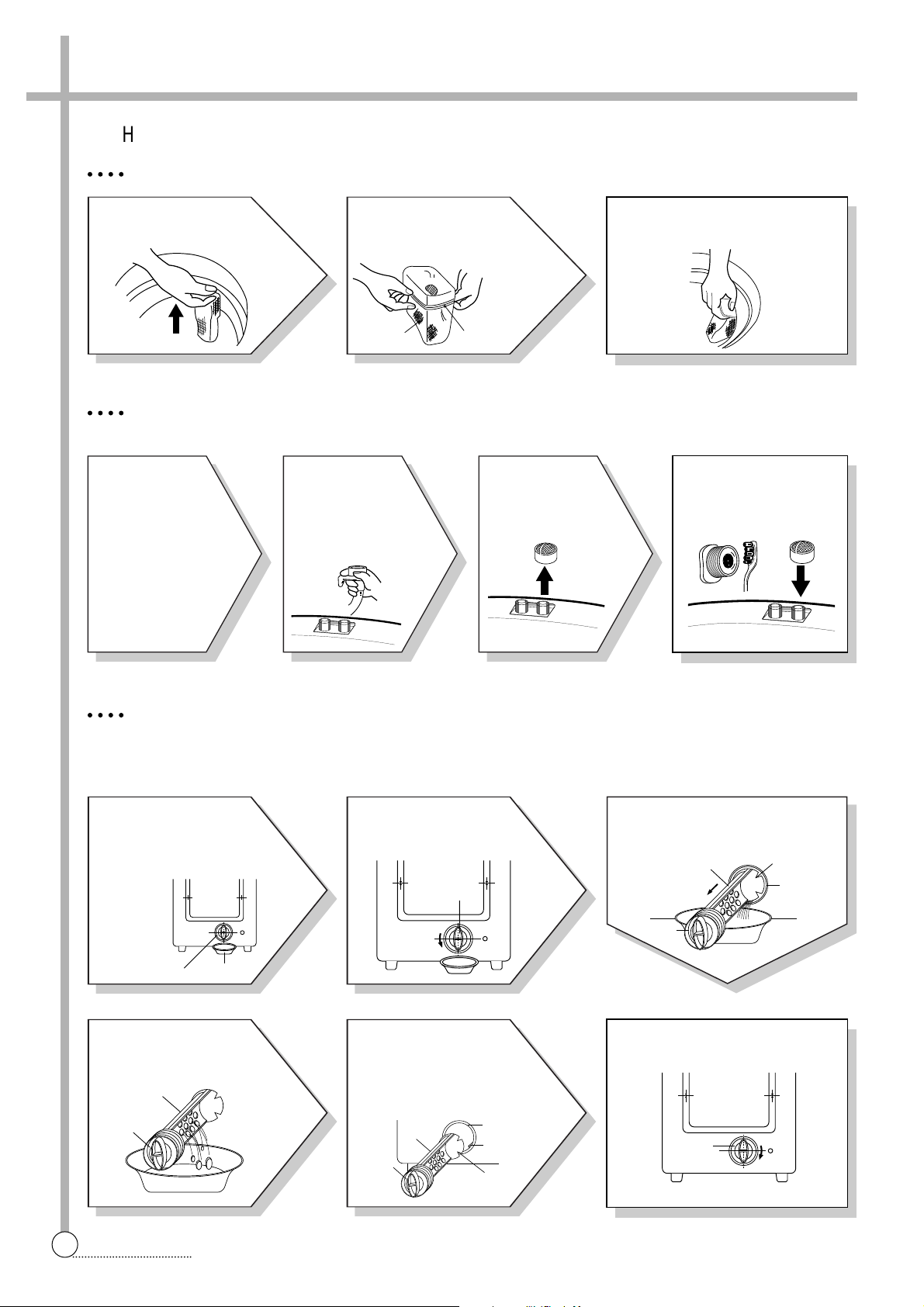
How To Clean The Filter
4
Remove the dirt
from the inlet filter
with a brush.
1
Pull the
power plug
out before
cleaning it.
2
Turn of f the
water supply
to the washer
and sperate the
3
Pull the
inlet filter out.
CLEANING THE LINT FILTER
CLEANING THE WATER INLET FILTER
• Clean the filter when water leaks from, the water inlet.
CLEANING THE DRAIN FILTER
• In case “U” shape drain hose, this filter’s equipped at the cack side of washer.
• This drain filter is to screen the foreign stuffs such as threads, coins, pins, buttons etc ...
• If the drain filter is not cleaned at proper time (every 10 times of use), Drain problem could be caused.
3
Return the filter as it was, and
insert the filter frame into the
slot.
1
Pull the Filter frame
upward.
2
Turn the lint filter
inside out, wash to
the lint off with water.
1
Put down the
remained water in the
hose. And put a container
under the filter to collect
water.
2
Turn the cap counter
clockwise.
3
Pull out the filter assembly off
the case of the main body.
6
Turn the cap clockwise tightly.
4
Clean the drain filter
removing the foreign
stuffs.
5
Put in the filter along the
guiding prominence of the
case. Please note the left
position of the filter adjusting
the groove to the guide rib.
FILTER
CONTAINER
CAP
SLIT
CASE
FILTER
CAP
CAP
FILTER
CAP
FILTER
CASE
GUIDE
RIB
SLIT
CAP
Filter Frame
Lint Filter
Page 7
4. FEATURE AND TECHNICAL EXPLANATION
7
EXPLANATION
WASH DRAIN SPIN FILL RINSE 1 DRAIN SPIN FILL RINSE 2 DRAIN •••
MOTOR C.W
SINGAL C.C.W
TIME(SEC.) 0.3 0.3 0.3 0.3 0.3 0.3 •••••••
35 SEC. (About 29 Times)
FILL WASH STOP WASH STOP
• 2’ 28’ 2’ 28’
SOAK PROCESS MAIN PROCESS
60 Minute
Feature of the Washing Machine
1 The first air bubble washing system in the world.
2 Quiet washing through the innovational low-noise design.
3 The wash effectiveness is much more enhanced because of the air bubble washing system.
4 The laundry detergent dissolves well in water because of the air bubble washing system.
5 The adoption of the water currents to adjust the unbalanced load.
6 One-touch operation system.
Water Current to Adjust the Unbalanced Load
It is a function to prevent eccentricity of the clothes after wash by rotating pulsator C.W and C.C.W for 35
seconds.(But, the SUIT course have no operation of the water currents to adjust the unbalnced load.)
EFFECT
It reduces vibration and noise effectively while spinning.
WATER FLOW
Function for Soak Wash
DISPLAY THE RESIDUAL TIME
When the SOAK WASH is selected, the total wash time increases because 60 minutes for soak process are added
to the time of main process.
PROGRESS
Automatic Water Supply System For Blanket Wash
The water level would be lowered because the blanket absorbs water at the beginning of washing. Therefore, after
30 seconds, the operation is interrupted to check the water level, and then the water is supplied again until the selected water level is reached.
‘ ’ mark indicates the operation of the water currents to adjust the unbalanced load.
NOTES
Page 8
8
EXPLANATION
FUNCTIONAL PRINCIPLE
1 The micom can remember the time from the begining of drain to reset point when the pressure switch reaches to
“OFF” point
2 In case of continuous draining, residual drain time is determined by micom.
Draining time as a whole = D + 90
Residual drain time.
The time remembered by micom.
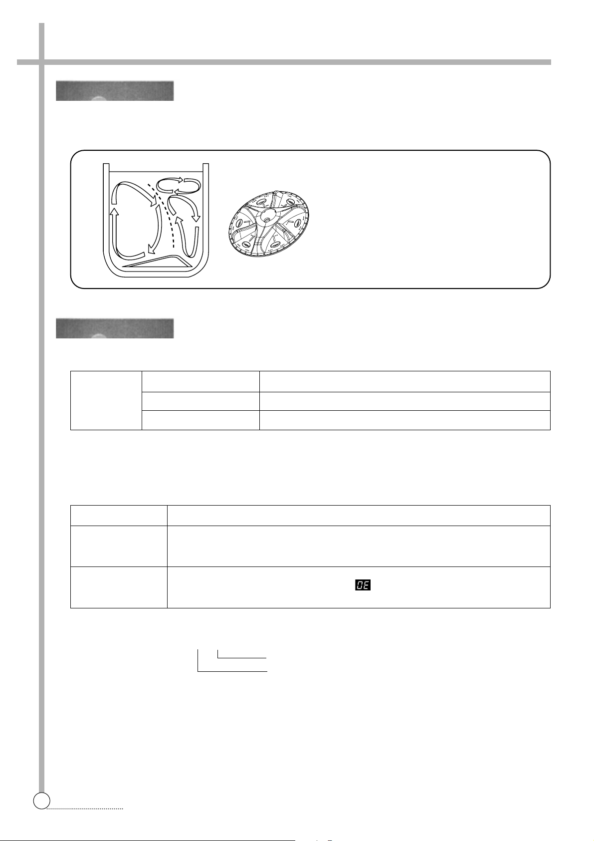
Asymmetrically designed pulsator
makes the cyclone water fow, which get
rid of the washing dead zone to
increase the washing effect and reduce
the entanglement of laundry.
Draining
Good draining The washer begins spin process after drainage.
condition
Bad draining Draininig time is prolonged.
No draining Program is stopped and gives the alarm.
Drain Time Movement of the Program
Less than
Continue draining
15 minutes
More than
Program stops and gives the alarm with blinked on display lamp.
15 minutes
Pulsator System
When the pulsator is rotated C.W or C.C.W at a high speed, it makes the cyclone water flow from the asymmetrically
designed pulsator as shown below.
Automatic Drainning time Adjustment
This system adjusts the draining time automatically according to the draining condition.
Page 9
9
EXPLANATION
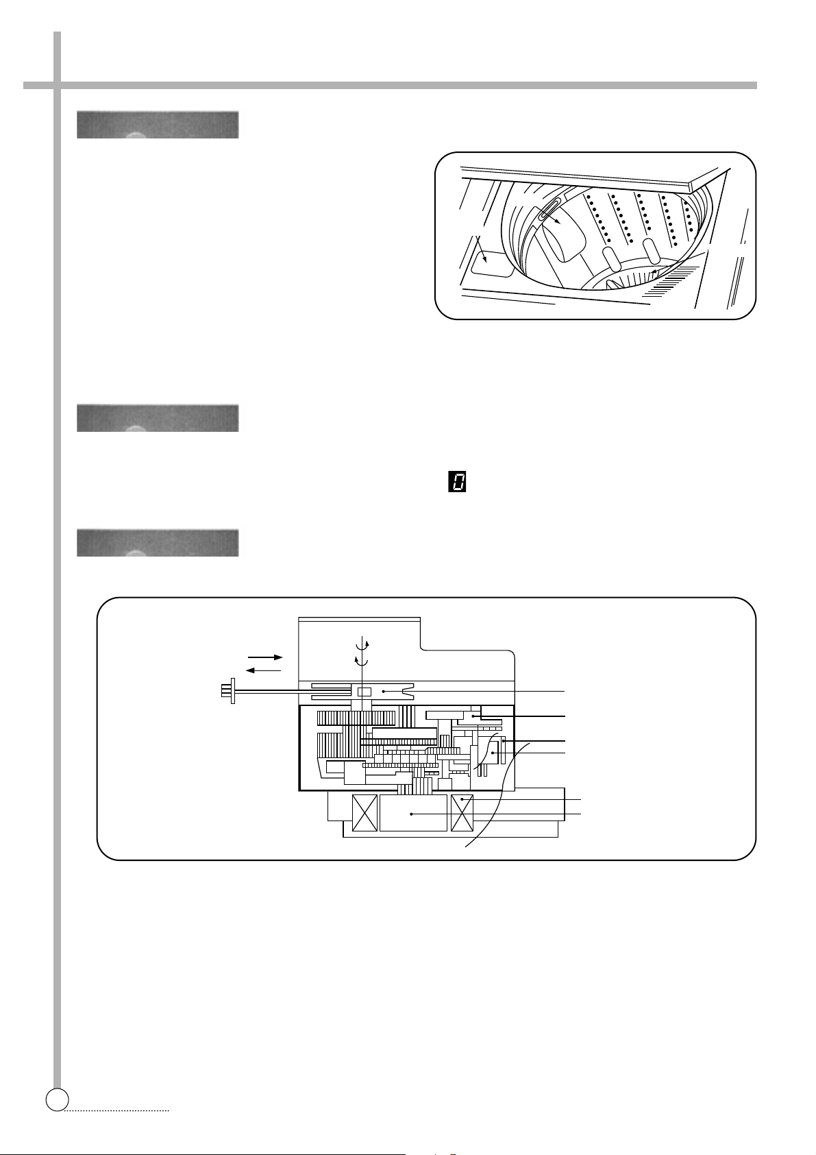
Automatic Unbalance Adjustment
Circulating-Water Course and Lint Filter
The alarm finished when you close the lid after opening
it. Check the unbalance of the wash load and the installation condition.
NOTES
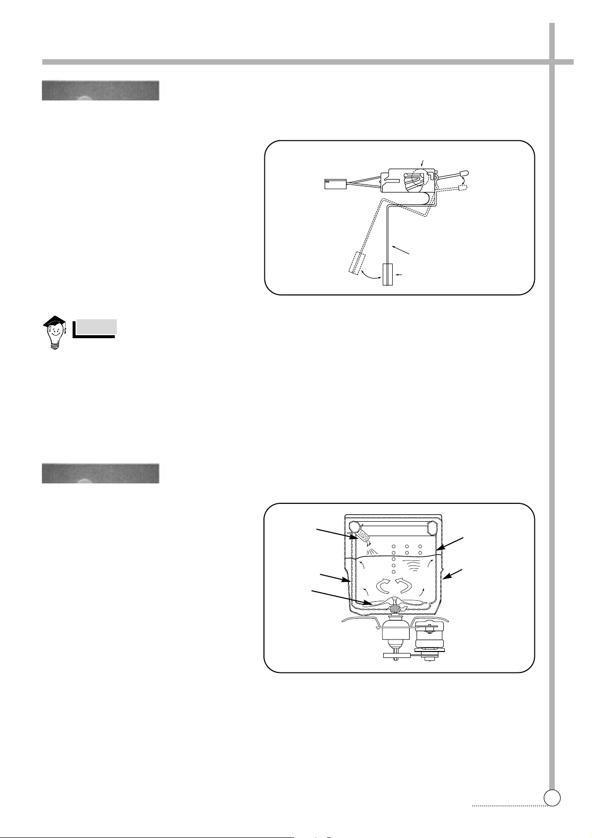
Filter
Tub
Outer tub
Water
channel
Pulsator
This system is to prevent abnormal vibration during intermittent spin and spin process.
FUNCTIONAL PRINCIPLE
1 When the lid is closed, the safety switch
contact is “ON” position.
2 In case that wash loads get uneven during
spin, the outer tub hits the safety switch
due to the serious vibration, and the spin
process is interrupted.
3 In case that P.C.B. ASS’Y gets “OFF” signal
from the safety switch, spin process are
stopped and rinse process is started automatically by P.C.B. ASS’Y.
4 If the safety switch is operated due to the
unbalance of the tub, the program is
stopped and the alarm is given.
CIRCULATING-WATER
The washing and rinsing effects have been
improved by adopting the water system in
which water in the tub is circulated in a
designed pattern.
When the pulsator rotates during the washing
or rinsing process, the water below the pulsator vanes creates a water currents as shown
in figure.
The water is then discharged from the upper
part of the tub through the water channel.
About 40 L/min. water is circulated at the ‘high’
water level, standard wash load and standard
water currents.
Position of
unbalanced load (OFF)
Contact of safety switch Lid closing
Lid opening
Contact lever A
Normal (ON)
Page 10
10
EXPLANATION
Much lint may be obtained according to the kind of
clothes to be washed and some of the lint may also
sticks to the clothes.
To minimize this possibility a lint filter is provided on
the upper part of the tub to filter the wash water as it
is discharged from the water channel. It is good to
use the lint filter during washing.
HOW TO REPLACE LINT FILTER
1 Pull the filter frame upward.
2 Turn the lint filter inside out, and wash the lint off with water.
3 Return the filter as it was, and fix the filter frame to the slot.
When the START/HOLD button is pressed, the residual time (min.) is displayed on the time indicator, and it will be
counted down according to process.
When operation is finished, the TIME INDICATOR will light up .
STRUCTURE
FUNCTIONAL PRINCIPLE
1 When the DRAIN MOTOR connected to the power source, the DRAIN MOTOR rotates with 900 r.p.m and
revolves the pulley by gear assembly for reducing.
2 When the pulley is rotated, the pulley winds the wire to open the drain valve.
3 Therefore, rotation of pulley changed to the linear moving of wire.
4 The wire pulls the brake lever of Gear Mechanism Ass’y within 5 seconds.
5 After the wire pulled, gear assembly is separated from motor and condition of pulling is held by operation of the
lever.
6 When the power is turned off, the drain valve is closed because the wire returns to original position.
Bleach Inlet
Filter
Pulsator
Pull
Loosen
Pulley
Lever
Inductive ring
Magnet
Coil of motor
Magnet of motor
Lint Filter
Residual Time Display
Drain Motor
Bleach
Inlet
Filter
Pulsator
Page 11
11
EXPLANATION
The proper water currents is made by the rotation of pulsator at a low speed to prevent the damage to the small
sized clothes.
Planetary gear
Sun gear
Internal gear
Pulsator
1 revolution
5 revolutions
Gear pulley
V-belt
Gear unit as
Motor
Motor
1490 r.p.m
(50Hz)
Gear Unit as
Directly
1/5
Tub
640 r.p.m
Pulsator
128 r.p.m
Gear Pulley
640 r.p.m
Gear Mechanism Ass’y
Page 12
5. DIRECTIONS FOR DISASSEMBLY AND ADJUSTMENT
12
DIRECTIONS
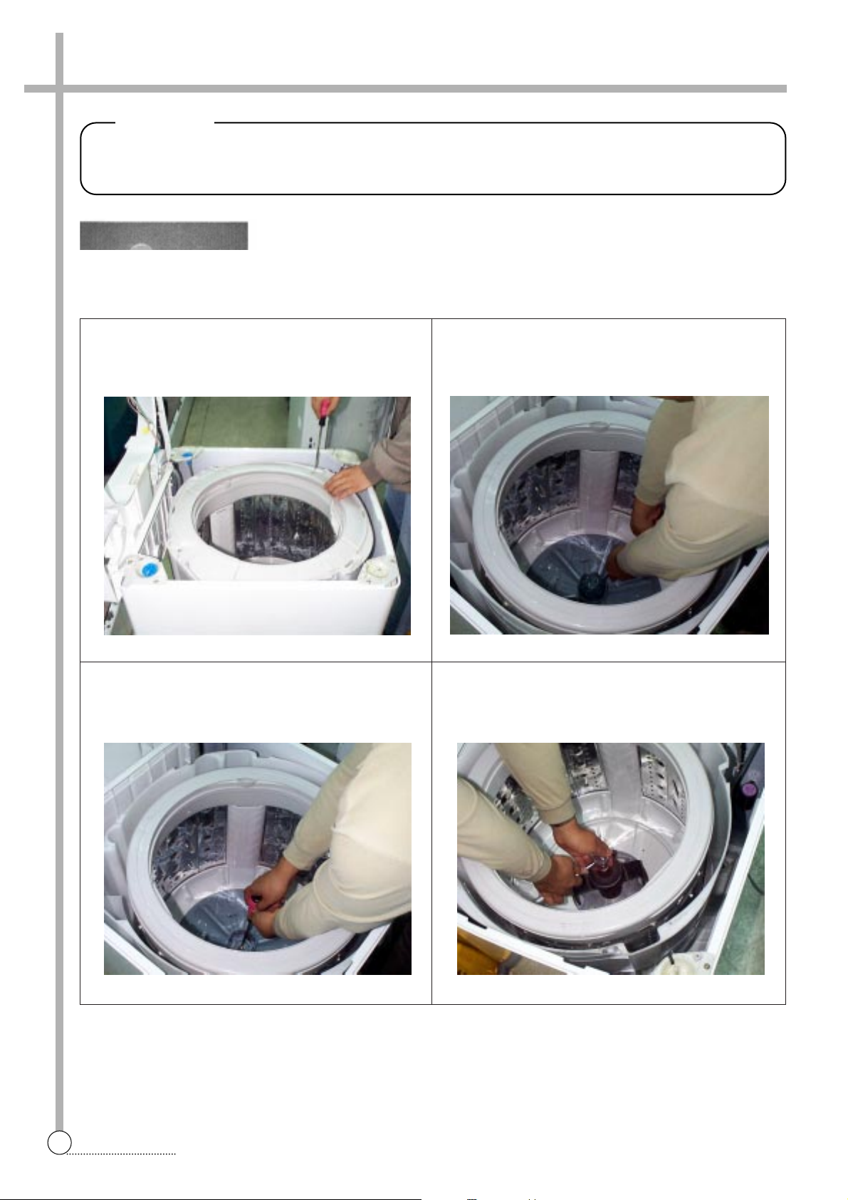
Gear Mechanism Ass’y Replacement
BEFORE ATTEMPTING TO SERVICE OR ADJUST ANY PART OF THE WASHING MACHINE, DISCONNECT
THE POWER CORD FROM THE ELECTRIC OUTLET .
WWaarrnniinngg
1 Raise the top plate on the outer cabinet.
2 Loosen four screws mounting outer tub cover and
remove outer tub cover from the tub ass’y.
4 Loosen the pulsator mounting screw and remove the
pulsator.
3 Remove the cap pulsator from the pulsator assy by
using screw driver
5 Remove the special nut by using “T” type box wrentch.
6 Remove the special washer.
GEAR MECHANISM ASSY REPLACEMENT
Page 13
1313
DIRECTIONS
To assemble the gear mechanism ass’y, reverse the disassembly procedure.
NOTES
7 Remove the tub i assy.
q Remove four special bolt of gear mechanism assy by
using a box wrentch.
8 Lay the front of the washer on the floor.
9 Remove four special bolts of gear protect by using a box
wrentch and remove gear protect.
0 Remove the V-belt.
wPull out the gear mechanism assy.
Page 14
14
DIRECTIONS
1 Lay the front of the washer on the floor.
2 Loosen two special screw of motor synchronous.
5 Turn the valve by using screw driver as shown in picture.
3 Take out the wire of motor synchronous from the braket.
4 Separate the motor synchronous from the base.
6 Remove the valve lid from the valve drain assy.
MOTOR SYNCHRONOUS AND V ALVE REPLACEMENT (NON PUMP MODEL)
Page 15
15
THE REPAIR
6. THE REPAIR METHOD OF GEAR MECHANISM FOR CLUTCH SPRING PROBLEM
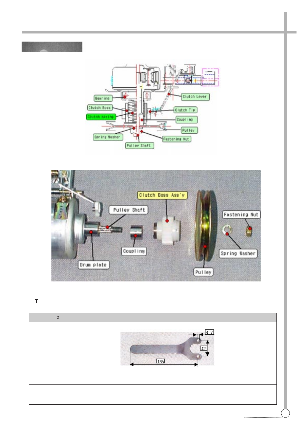
¡¡
‹
TOOL FOR REPLACING THE CLUTCH BOSS ASSEMBLE
¡¡
‹
Tool name Specification Q’ty
Fixing jig 1
Ratchet handle 1
Socket and extension bar socket : 10mm, 17mm per each
Some cotton yarn some
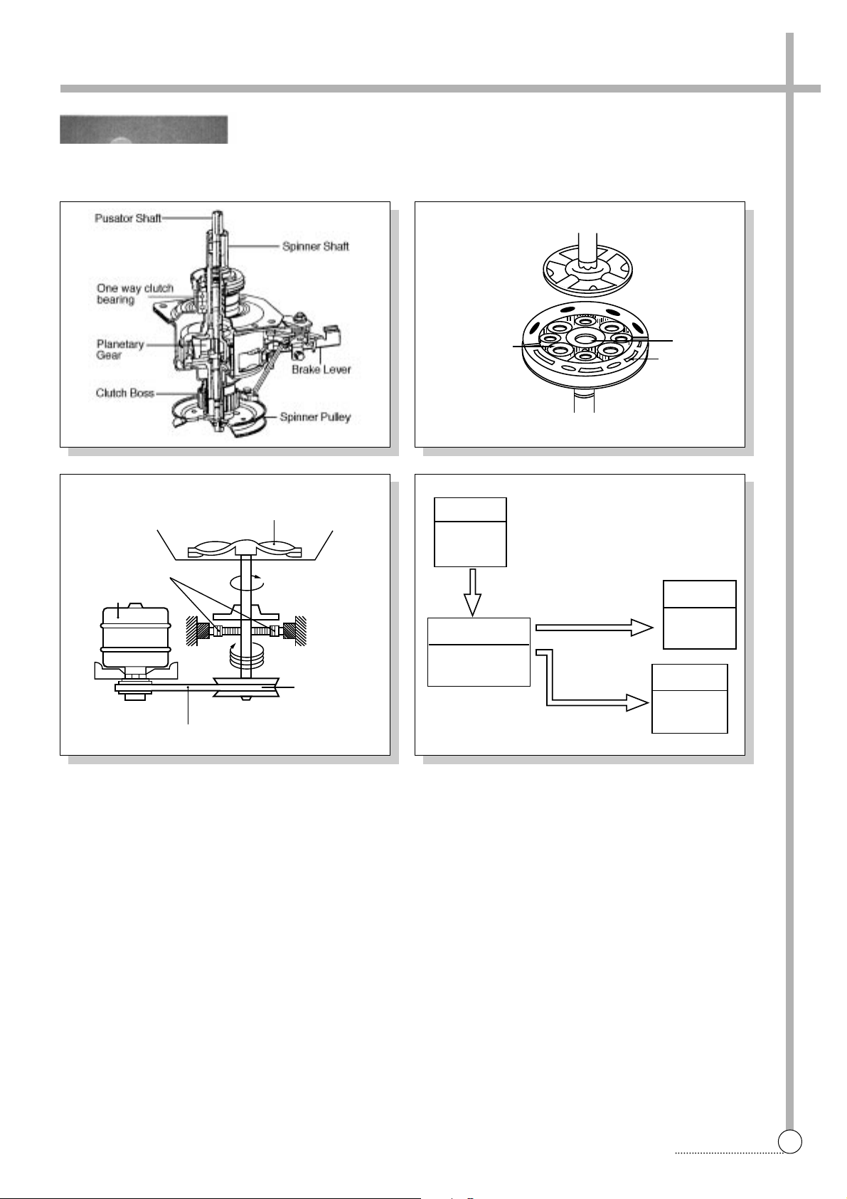
The Structure Of Gear Mechanism
Page 16
16
THE REPAIR
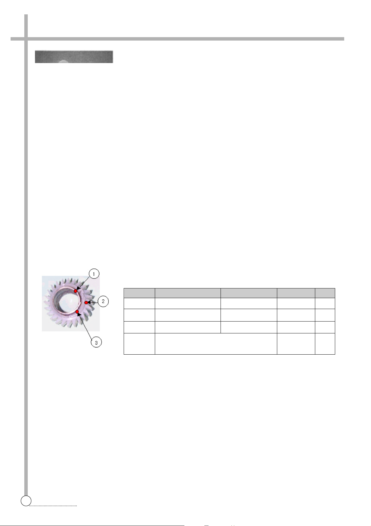
NO. P AR TS NAME SPECIFICATION CODE Q’TY
1 CLUTCH SPRING 1.5*1.5 36151 10000 1
2 CLUTCH BOSS PP 3619301300 1
3 GREASE beacon#325 3g
P ACKING P ACKING THE CLUTCH BOSS ASS’Y 1
METHOD BY USING VINYL PACK
1) THE LAUNDARY IS IN THE SPIN TUB UNEVENLY WHEN JUST STARTING SPIN PROCESS.
2) THEREFORE, IT CAUSE THE SERIOUS NOISE AND VIBRATION WHEN WASHING AND SPINNING
PROCESS OR SUPPLING WATER IRREGULARY WHEN SPINNING PROCESS
AND CAUSE SHORT OF SPIN PERFORMANCE.
IN THIS CASE, YOU MUST EMPTY THE SPIN TUB FIRST.
1) TO CHECK THE REVOLUTION OF SPIN TUB. IF THE SPIN TUB DOES NOT REVOLVE AND ONL Y
THE PULSAT OR IS TURNING, THAT IS CLUTCH SPRING DEFECT.
2) TO CHECK THE SPIN SPEED(RPM) BETWEEN SPIN TUB AND PULSATOR.
IF YOU FIND THE DIFFERENT SPIN SPEED BETWEEN SPIN TUB AND PUSATOR, THIS IS ALSO
CLUTCH SPRING DEFECT.
IN THIS CASE, WE ARE GOING TO SUPPLY THE CLUTCH BOSS ASSEMBLY INSTEAD OF GEAR
MECHANISM ASSEMBLEY. PLEASE REFER TO FOLLOWING FIG.
PROBLEM
CHECKING METHOD
THE CLUTCH BOSS ASSEMBLY
CLUTCH BOSS ASS’Y P AR T CORD : 3619301400
How To Check The Clutch Spring Problem
Page 17
17
THE REPAIR
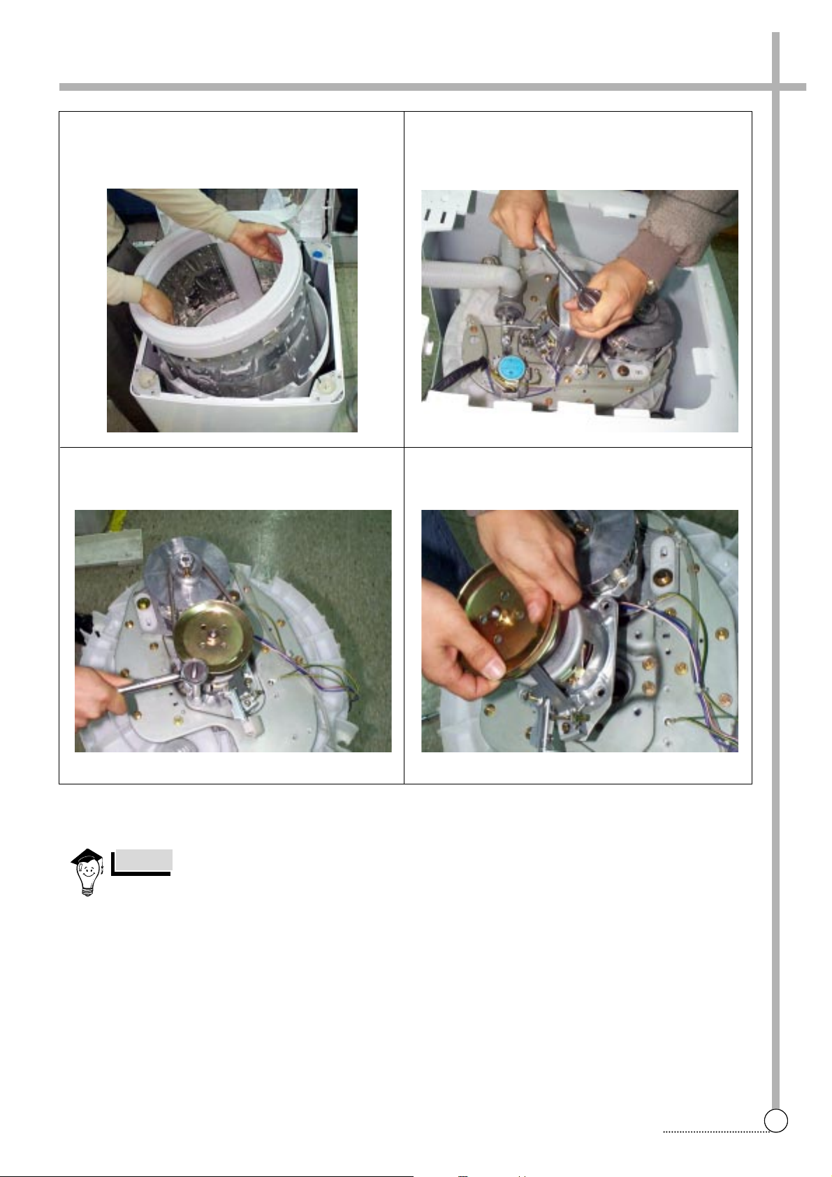
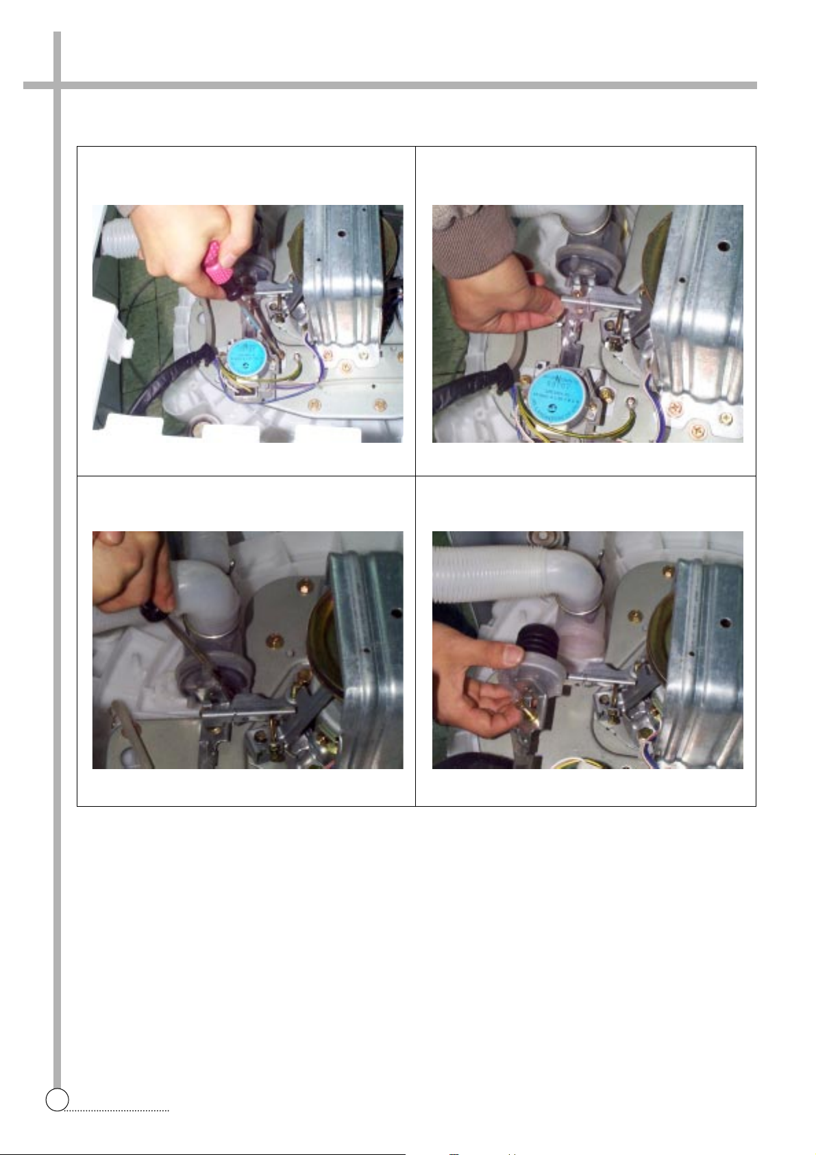
No. Process Notice
Disassemble 1
1
2
3
4
Release screws marked 4-point
Remove the protector
Remove the v-belt
Loosen the fastening nut
Disassemble the spring washer
Use wrench or driver
- ratchet handle
- extension bar
- socket : 10mm
Use fixing jig for pulley as to
see fig 1.
and 17mm-socket for nut
Take out plain washer if it has
The Process Of Disassemble
Page 18

18
THE REPAIR
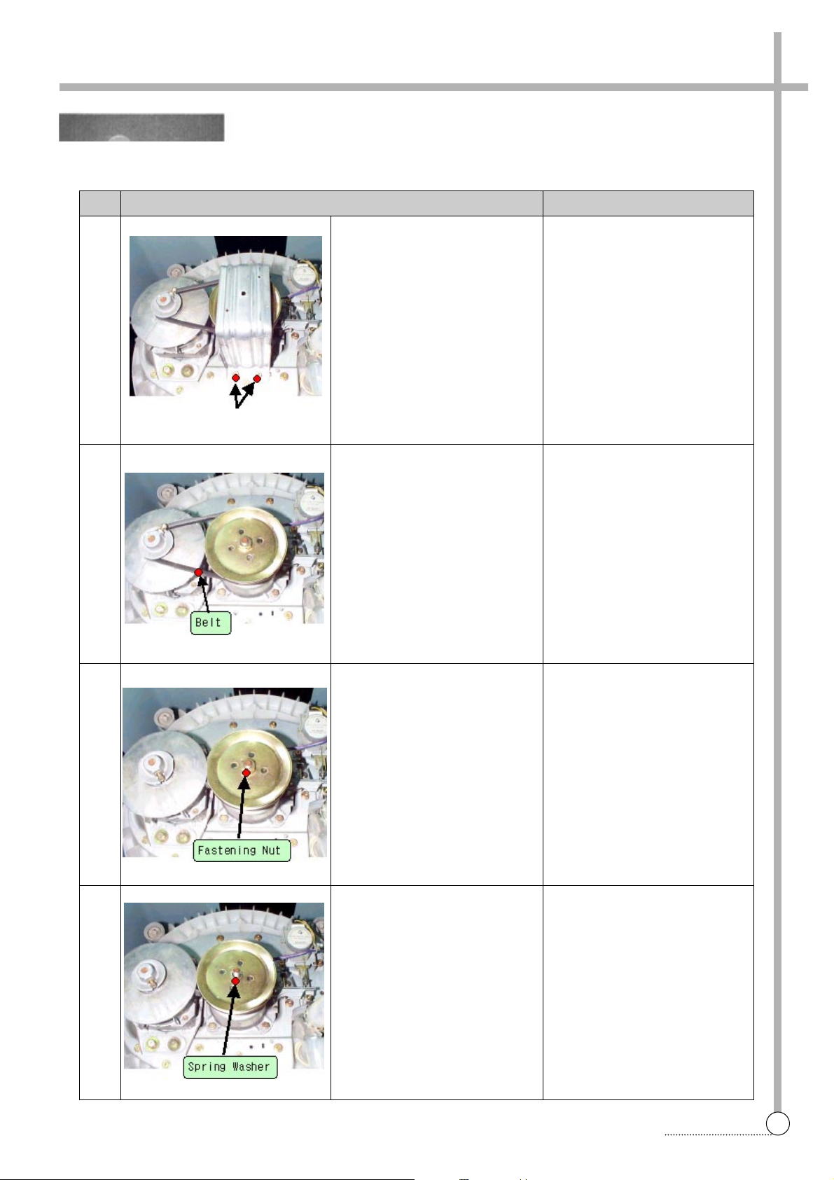
No. Process Notice
Disassemble 2
5
6
7
8
Disassemble the pulley
Disassemble the clutch boss
assembly
Separate coupling from clutch
boss ass’y
Cleaning
Catch the boss and pull
upward with spiral rotate in the
clockwise direction
Clean the drum plate, coupling
surface and contact face
between drum plate and coupling
It is necessary to keep cotton
piece goods being dry and
clean
Page 19

19
THE REPAIR
No. Process Notice
Assemble 1
1
2
3
4
Assemble the coupling
Assemble the new clutch boss
ass’y
Assemble the pulley
Assemble the spring washer
Check the uneven face of coupling is assembled upward
- Push in the clutch boss ass’y
with rotating on the clockwise
direction.
-
After assembling, rotate on the
clockwise more 2~3 teeth and
pull out the pulley shaft upward
If there was plain washer, you
have to assemble plain washer
the first and then assemble
spring washer
The Process Of Assemble
Page 20

20
THE REPAIR
No. Process Notice
Assemble 2
5
6
7
8
Assemble the fastening nut
Assemble the Belt
Assemble the protector
Final checking
- Use fixing jig and 17mm
socket wrench
as if disassembling,
as fastening torque about
100~200kgf-cm.
- Check the end-play, up and
downward and check the binding force, too much or not on
bi-direct of rotation.
Finally, check the distance
between brake lever and control bolt. (2~3mm)
Also, check the interferance
depth both clutch tip and clutch
boss(3.5~4.5mm)
Clutch Tip
Drain
V alve
Synchronous
Motor
3.5~4.5
keep distance 2~3mm
Page 21

21
THE REPAIR
1 separate the back cover from
washing machine
4 turn the case filter ass’y and sepa-
rate it from the drain motor
7 assemble the case filter ass’y that
purchased
0 assemble the hose drain I to the
case filter with bond & clamp
2 remove two screws
5 separate the drain hose i from the
case filter ass’y
8 tie up three screws
q assemble the cavitation hose to
the case filter with bond & clamp
3 remove three screws
6 separate the cavitation hose from
the case filter ass’y
9 tie up two screws
w assemble the back cover to the
washing machine
REPLACE THE CASE FILTER ASS’Y
Page 22

22
DIRECTIONS
7. TECHNICAL POINT
Replacing Process of Synchronous Motor Wire
– replace the New G/M
– replace the Link valve drain
from Plate valve connector
– insert the Link v/v drain into the G/M Lever with pulling the Lever toward
Syncronous Motor
– to assemble the wire of Syncronous Motor to the inside of Link valve
drain with pulling the Lever toward Syncronous Motor
Valve Drain Assy and Gear Mechanism
We changed the shape of the Lever because of preventing water leakage and noise of G/M.
Please refer to the changing date as following table
OLD type NEW type
V alve Drain Assy
G/M with Tub O
Part name Part Cord Specification Part Cord Specification
Plate valve conn’r 4509k78070 SECC –
Link valve drain – 3617801900 POM
Gear Mechanism
367305900 GM-8094-KS0X0
3617307610 GM-1300-KS6P0
367305800 GM-1094, KELV AR
Syncronous Motor
4505D45100 L=56.5/18mm(1 10-130V/60Hz) 4505E45120 L=64.5/23mm(110-130V/60Hz)
3966010200 L=56.5/18mm(220-240V/50Hz) 3966010220 L=64.5/23mm(220-240V/50Hz)
Page 23

OLD type NEW type
Appearance
Shaft design
Pulley design
Part name Part Cord Specification Part Cord Specification
3964220620 110V/60Hz 3966221 101 110-127V/60Hz W1D46CA012
39647201 10 127V/60Hz
3964320100 220V/60Hz 39643211 11 220V/60Hz W1D46UA012
3964010160 220-240V/50Hz 396431 1311
220-240V/50Hz W1D46V A012-S
Motor condenser 3964220420 110V/60Hz 396422121 1 110V/60Hz W1D50CA012-S
(DWF-1094) 3964820520 127V/60Hz 396482131 1 127V/60Hz W1D50JA012-S
3610019720 220V/60Hz 396432121 1 220V/60Hz W1D50UA012
3964310530 220V/50Hz 396451041 1 220V/50Hz W1D50VA012
3964610320 240V/50Hz 3964610321 240V/50Hz F33-2C-S
Pulley motor assy 3618401400
M-TYPE DS=10 DP=48.5 60Hz
3618432000
M-TYPE DS=10 DP=48.5 60Hz
3614801420
M-TYPE DS=10 DP=53.0 50Hz
3618431900
M-TYPE DS=10 DP=53.0 50Hz
Motor cushion down 3611502800 POM, H=18mm 3611502700 POM, H=8.0mm
OLD type NEW type
Appearance
Shaft design
Pulley design
Part name Part Cord Specification Part Cord Specification
Motor condenser 3964220620 110V/60Hz 3966221 101 110-127V/60Hz W1D46CA012
(DWF-8094, 7094) 3964720110 127V/60Hz
3964320160 220V/60Hz 39643211 11 220V/60Hz W1D46UA012
3964010160 220-240V/50Hz 396431 1311
220-240V/50Hz W1D46V A012-S
Motor condenser 3964220420 110V/60Hz 396422121 1 110V/60Hz W1D50CA012-S
(DWF-1094) 3964820520 127V/60Hz 396482131 1 127V/60Hz W1D50JA012-S
3610019720 220V/60Hz 396432121 1 220V/60Hz W1D50UA012
3964310530 220V/50Hz 396451041 1 220V/50Hz W1D50VA012
3964610320 240V/50Hz 3964610321 240V/50Hz F33-2C-S
Pulley motor assy 3618401400
M-TYPE DS=10 DP=48.5 60Hz
3618432000
M-TYPE DS=10 DP=48.5 60Hz
3614801420
M-TYPE DS=10 DP=53.0 50Hz
3618431900
M-TYPE DS=10 DP=53.0 50Hz
Motor cushion down 3611502800 POM, H=18mm 3611502700 POM, H=8.0mm
23
DIRECTIONS
– check the assemble condition by moving Lever 2~3 times
Pulley Motor Assy
In case of replacing the Motor from OLD type to NEW type, Daewoo will supply Motor condenser, Pulley motor assy,
Motor Cushion (down) together.
Al – diecasting, bolt and nut
D cut
M – 8 tapping
press type, washer and net
Page 24

24
Switch Safety Ass’y
Replacing method from OLD type to NEW type.
Please use the “Special connector’ which will be supplied by Daewoo.
Switch Safety Ass’y
OLD type NEW type
Appearance
Structure lead wire type terminal type
Part name Part Cord Specification Part Cord Specification
Sensor pressure assy 3614800960 CDN-D7N 3614801 110 D8T , TERMINAL
OLD type NEW type
Appearance
Structure lead wire type terminal type
Part name Part Cord Specification Part Cord Specification
Switch safety assy 3619003100 SF-040A 3619003101 SF-030A, CU/T=14mm
(DWF-8094, 7094) 3619003110 SF-040F 36190031 11 SF-030S, CU/T=9mm
3619003130 SF-041A(DWF-8094PM) 3619003131
SF-031A, CU/T=9mm Australia
3619003120 SF-040Z(DWF-7094PM) 3619003121
SF-030Z, CU/T=14mm Australia
Switch safety assy 3619008920 SF-040T 3619008921 SF-030T, CU/T=0.5mm
(DWF-1094) 3619003190 SF-040A5 3619003191
SF-030T, CU/T=0.5mm Australia
Connector
Page 25

8. TROUBLE SHOOTING GUIDE
25
PROBLEM
WATER IS
NOT SUPPLIED.
CHECK POINT
Do you open the water
tap?
Is the filter of the water
inlet valve clogged with
dirt?
Is the water pressure
sufficient?
(0.3~8 kgf/cm
2
)
Does the water inlet
valve make operating
sound?
Is the connector or the
terminal connected
properly?
Is the output voltage of
the P.C.B normal?
CAUSE
Water inlet valve
is defective.
Improper connection of
the connector or the terminal.
P.C.B AS is defective.
Lead wire is defective.
SOLUTION
Change water inlet valve.
Open the water tap.
Clean the filter.
Increase the water pressure.
Connect the connector or
the terminal properly.
Change the P.C.B AS.
Change the lead wires.
NO
YES
NO
YES
NO
YES
YES
YES
YES
NO
NO
NO
NOTE : Open the water tap fully and measure
the flow rate.
From the upper results, you know that the flow rate more than
11.5
l/min. is essential for water supply.
Flow
1 1.5 15.0 18.0 20.3 24.1 27.4
rate(l/min.)
Water pressure
0.3 0.4 0.5 0.6 0.8 1.0
(Kgf/cm
2
)
1. When replace the P.C.B. ASS’Y do not scratch the surface of the P .C.B. ASS’Y.
2. Disconnect the power cord from the electric outlet.
NOTES
Concerning Water Supply
Page 26

26
TROUBLE SHOOTING
PROBLEM
WATER SUPPL Y IS NOT
STOPPED.
CHECK POINT
Does the water supply
continue while the power
is turned off?
Does the water supply start
as soon as you press the
power switch?
Operate the washer after
setting the water level to
“HIGH”
Does the water supply
continue after the water
reaches to the “HIGH”
level?
Is the air tube of water
level switch kinked or
deformed?
CAUSE SOLUTION
Change the water inlet
valve.
The water inlet valve is
defective.
The triac of P.C.B is
defective.
Change the P.C.B ASS’Y.
Normal operation.
Change the air tube.Air tube is defective.
Change the pressure
switch.
Pressure switch is defective.
PROBLEM
THE PULSA T OR DOES
NOT ROTATE
EVEN IF THE
WATER IS
SUPPLED.
CHECK POINT
Does the motor operate after finishing water supply?
Does the motor make
operating sound?
Is the connection condition of capacitor terminal good?
Does pulsator rotate in
only one direction?
Is the motor coil disconnected?
Is the V-belt worn out?
The triac of P.C.B is
defective.
Motor is defective.
Improper connection
V-belt is defective.
Change the P.C.B
ASS’Y.
Normal
Change the motor.
Connect the terminal
properly.
Change the V-belt.
Change the motor.
CAUSE SOLUTION
YES
YES
YES
NO
NO
YES
YES
NO
YES
YES
YES
NO
NO
NO
NO
NO
NO
NO
YES
Concerning Washing
Page 27

27
TROUBLE SHOOTING
PROBLEM
THE WASHER
DOES NOT
DRAIN.
CHECK POINT
Do you install the
drain hose properly?
Is the foreign matter
accumulated inside
the pump housig?
Is the output voltage of
the drain pump normal?
CAUSE SOLUTION
Install the drain hose
properly.
Remove the foreign matter from the pump housing
Change the Drain pump
Change the P.C.B ASS’Y.
Improper installation
Malfunction of drainage
by the foreign matter
Drain pump is defective
P.C.B ASS’Y is defective.
YES
NO
NO
NO
YES
YES
Concerning Draining
Page 28

28
TROUBLE SHOOTING
PROBLEM
THE WASHER
DOES NOT
SPIN.
CHECK POINT
Is the lid open?
Does the door switch
operate normally?
Does the safety switch
operate normally?
Does the pulsator rotate
while the tub does not
rotate?
Is the connector of
P.C.B ASS‘Y connected
properly?
Is the input
voltage of the drain
motor normal?
Is the V-belt worn out?
Is the input voltage of
motor normal?
Is the connection condition of capacitor terminal good?
CAUSE SOLUTION
Close the lid.
Change the door switch.
Change the safety
switch.
Connect the connector
properly.
Change P.C.B ASS’Y.
Change the drain motor.
Change the P.C.B ASS’Y.
Change the V-belt.
Change the motor.
Connect the terminal correctly.
Change the P.C.B ASS’Y.
Door switch is defective.
Safety switch is defective.
Improper connection of
the connector.
P.C.B. ASS’Y is defective.
Drain motor is defective.
P.C.B ASS’Y is defective.
V-belt is defective.
Motor is defective.
Improper connection.
P.C.B ASS’Y is defective.
NO
YES
YES
NO
NO
YES
YES
YES
NO
NO
NO
NO
YES
YES
NO YES
Concerning Spinning
Page 29

29
TROUBLE SHOOTING
NO
NO
NO
PROBLEM
THE INDICATOR
LAMPS(L.E.D)
DO NOT LIGHT
UP WHEN THE
POWER BUTTON IS
PRESSED.
PROGRESS
LAMPS(LED)
DO NOT LIGHT
UP.
MOTOR
ROT ATES
WHEN
ST AR T/HOLD
BUTTON IS
NOT
PRESSED.
ABNORMAL
NOISE DURING WASH
PROCESS.
CHECK POINT
Is the plug connect-ed
to electric outlet?
Is the condition of
power button good?
Is the connector of the
P.C.B. ASS’Y connected properly?
Is input voltage of the
transformer normal?
Do you press
ST ART/HOLD button?
Does the pressure switch
operate normally?
Check the output voltage
of P.C.B ASS’Y
Is the strange noise generated when the pulsator
rotates in TEST MODE
of P.C.B ASS’Y?
Is the V-belt worn out?
CAUSE SOLUTION
Connect the plug.
Change P.C.B ASS’Y.
Change Fuse
Connect the connector
properly.
Change the transformer.
Change P.C.B ASS’Y.
Press START/HOLD button.
Replace P.C.B ASS’Y.
Change the pressure
switch.
Change P.C.B ASS’Y.
Remove the foreign matter.
Change the V-belt.
Power button is defective
Improper connection of
the connector.
Transformer is defective
P.C.B. ASS’Y is defective.
P.C.B ASS’Y is defective.
Pressure switch is defective.
P.C.B ASS’Y is defective
There is foreign matter
between pulsator and
tub.
V-belt is defective.
NO
YES
YES
YES
YES
NO
NO
YES
YES
Abnormal
YES
YES
NO
NO
Is Fuse opended?
Concerning Operation
Page 30

30
9. PRESENTATION OF THE P.C.B ASS’Y
MESSAGE CAUSE SOLUTION
Improper installation of drain hose.
The drain hose is blocked up by foreign
matter.
Drain motor is inferior.
The water tap is closed.
The water inlet filter clogged.
It passes over the 60 minutes, yet it doesn’t
come to assigned water level.
Wash loads get uneven during spin.
Poor installation of the unit.
The lid is opened.
The safety switch is inferior.
The load sensing is inferior. After the load
sensing operates about 15 seconds, the
message is displayed during 0.5 second
and water level is always fixed ‘high’.
The water level sensing is inferior.
Install drain hose properly.
Remove foreign matter from drain hose.
Change drain motor.
Open the water tap.
Clean the water inlet filter.
Check whether or not is comes to the
assigned water level.
Re-set wash loads evenly.
Proper installation.
Close the lid.
Change the safety switch.
Change the P.C.B. ASS’Y.
Check the water level sensor and the
contact part of the connector.
Concerning Error Message
Page 31

31
WIRING DIAGRAM
APPENDIX
§§
è
Wiring Diagram [Dwf-7094 non-pump]
Page 32

32
WIRING DIAGRAM
§§
è
[Dwf-7094 Non-Pump, Single Valve]
Page 33

33
WIRING DIAGRAM
§§
è
[Dwf-7094 Pump]
Page 34

34
WIRING DIAGRAM
§§
è
[Dwf-8094, 1094 non-pump]
Page 35

35
WIRING DIAGRAM
§§
è
[Dwf-8094, 1094 non-pump, single valve]
Page 36

36
WIRING DIAGRAM
§§
è
[Dwf-8094, 1094 pump]
Page 37

37
PARTS DIAGRAM
§§
è
Parts Diagram
Page 38

38
PARTS DIAGRAM
Page 39

39
PARTS DIAGRAM
Page 40

40
PARTS DIAGRAM
Page 41

NO PARTS NAME PARTS CODE EA DESCRIPTION REMARK
A01 GASKET VALVE 3612300110 2 PVC-S
1EA;SINGLE VALVE
A02 PANEL B 3614218500 1 ABS
3615405560
1
220V/60Hz
DWF-8094CLE
3615406660 DWF-7094CLE
VALVE INLET AS 3615405571
1 220-240V/50Hz
DWF-8094CNE
(ONLY COLD) 3615406671 DWF-7094CNE
3615405550
1 110-130V/60Hz
DWF-8094CTE
3615406650 DWF-7094CTE
A03
3615405500
1 220V/60Hz
DWF-8094PL
3615406600 DWF-7094PL
3615405531
1 220-240V/50Hz
DWF-8094PN
VALVE INLET AS
3615406631 DWF-7094PN
3615407500
1
220-240V/50Hz DWF-8094PM
3615407600 (AUSTRALIA) DWF-7094PM
3615405520
1 110-130V/60Hz
DWF-8094PT
3615406620 DWF-7094PT
A05 HINGE DOOR 3612902400 2 POLYACETAL
A06 BUBBLE PUMP AS
3618918800
1
AC 110-130V/50,60Hz HOSE=500mm
3618919400 AC 220-240V/50,60Hz HOSE=500mm
A07 SENSOR PRESSURE 3614801110 1 D8T, TERMINAL
5EP1048010 T5-V1
AC 110-130V
A08 TRANS POWER
5EP1048020
1
T5-V1F
5EP1048030 T5-V2
AC 220-240V
5EP1048040 T5-V2F
3619003101
SF-030A, CU/T=14, #187 7094, 8094
SWITCH SAFETY AS
3619003111
1
SF-030S, CU/T=9, #187
7094CLE, 8094CNE
A09
3619003131
SF-031A, CU/T=9, #187
8094(AUSTRALIA)
3619003121
SF-030Z, CU/T=14, #187
7094(AUSTRALIA)
A10 PLATE T 3614514800 1 ABS
A11 CAP SOFTENER 3610907800 1 PP
A12 NOZZLE DETERGENT 3618101700 1 PP
A13 CASE DETERGENT 3611114700 1 PP
A14 SPRING DOOR 3615107910 1 SUS304 D=1.8
A15 DOOR B 3611718200 1 ABS
A16 DOOR F 3611718100 1 ABS
A17 HANDLE DOOR 3612603500 1 ABS
A18 – – – –
A19 SPECIAL BOLT 3616001200 2 T1 TRS 5x73
41
PARTS DIAGRAM
§§
è
Parts List
1. DWF-8094, DWF-7094
Page 42

NO PARTS NAME PARTS CODE EA DESCRIPTION REMARK
A20 CAP 3610906710 2 PP
A21 PANEL F 3614218640 1 ABS
A22
UNIT FUSE FILTER
3618914811
1
AC 250V/5A, FERRITE 220-240V
3618918411 AC 250V/8A, FERRITE 110-130V
PRPSSWXZ00 DWF-8094G1/ME DUAL VALVE
PRPSSWX200 DWF-8094CNE/CLE
SINGLE VALVE
PRPSSWX201 DWF-8094CTE/CME
A23 PCB AS
PRPSSWX100
1
DWF-8094PT/PN/PM/PL PUMP
PRPSSWWX00 DWF-7094G3/M DUAL VALVE
PRPSSWWZ00 DWF-7094CNE/CME
SINGLE VALVE
PRPSSWWZ01 DWF-7094CTE
PRPSSWWY00 DWF-7094PT/PN/PM/PL PUMP
3612726911 250V/315mA
SINGLE VALVE
HARNESS AS
3612726931 250V/600mA
(DWF-8094)
3612726921 1 250V/315mA
PUMP
3612726941 250V/600mA
A24
3612727201
250V/315mA, DWF-8094ME
DUAL VALVE
3612727211 250V/315mA
SINGLE VALVE
HARNESS AS
3612727231 250V/600mA
(DWF-7094)
3612727221 1 250V/315mA
PUMP
3612727241 250V/600mA
3612727201
250V/315mA, DWF-7094ME
DUAL VALVE
3611302900 3x0.75, 300x2, L=1800 CP-2PIN
A25 CORD POWER AS
3611302800
1
A VCTFK 2x0.75 2.3M F-2PIN
3611302600 F H05W 3x0.75 2.3M ITALIAN 3PIN
3611303300 GTSA-3 3x0.75 GY ARGENTINE
A26 CLAMP 4500D08180 2 SWC BUBB ID=12.5 DWF-8094
A27 HOSE SHOWER AS 3613223200 1 HOSE+ABSORBER DWF-8094
B02
HOSE DRAIN O 3613213560 1 EVA, L=950mm NON-PUMP
HOSE DRAIN O AS 3613218800 1 PE-LD/EVA, L=1600 PUMP
B03 PLATE UPPER
3614501900 1 PP DWF-8094
3614506200 1 PP DWF-7094
B04 COVER B 3611414010 1 SGCC 372*508*0.4T
B05 – – – – DWF-1094
B06 – – – – DWF-1094
B07 – – – – DWF-1094
B08 – – – – DWF-1094
B09 – – – – DWF-1094
B10 ASSY CONDENSER
3618921500
1
54.0µF+60µH, L=470 110V/60Hz
3618921900 41.6µF+60µH, L=470 127V/60Hz
PARTS DIAGRAM
42
Page 43

43
PARTS DIAGRAM
NO PARTS NAME PARTS CODE EA DESCRIPTION REMARK
3618921000 13.5µF+60µH, L=470 220V/50,60Hz
3618920800 11.4µF+60µH, L=470 240V/50Hz
B11 CABINET AS
3610808310
1
PAINTING DWF-8094
3610808320 PAINTING DWF-7094
B12 HANDLE CABINET 3612603300 2 PP
B13 BASE U 3610303100 1 PP
B14 LEG FIX 3617703000 2 SBS
B15 LEG ADJUST AS 3617702100 2 DWF-1089W2
B16 COVER UNDER 3611402711 1 PP
B17 HARNESS OUTER 3610068700 1 50/0.18 GREEN
B20 COVER PUMP
3611405320
1
PP(B360F) PUMP MODEL
3611405301
UL/CSA(466FWU,HFH-400)
PUMP MODEL
B21 SCREW TAPPING 7122501611 2 T2 TRS 5x16 MFZN PUMP MODEL
3618957310 AC110-127V/60Hz DWF-**94PT/PS
B22
MOTOR SHADED POLE
3618957280
1
AC 220V/60Hz DWF-**94PL
3618957250 AC 220V/50Hz DWF-**94PN
3618957220 AC 240V/50Hz DWF-**94PM
B23 FILTER AS 3611901530 1 DWF-5590DPNF, E-TYPE PUMP MODEL
B24 FRAME TOP 3612200100 1 PP
C01 BALANCER AS
3616101600
1
DWF-8094
3616101700 DWF-7094
C02 FILTER 4505E82014 1 POLYESTER FILTER AS
C03 FRAME FILTER 4505E82021 1 PP :4505E82002
C04 – – – –
C05 SPECIAL SCREW 3616003700 24 SUS 5.5x16
C06 GUIDE FILTER AS
3612502200
1
DWF-8094
3612502400 DWF-7094
C07 TUB
3618816210
1
SUS430D DWF-8094
3618801800 SUS430D DWF-7094
C08 TUB U
3618802001
1
PP, -M/B DWF-8094
3618802101 PP, -M/B DWF-7094
C09 SPECIAL NUT 4507D83080 1 SUS 304
C11 FLANGE TUB
3617200600
1
ADC 12, VE1 DWF-8094
3617200610 ADC 10, 6.6-7.0kg DWF-7094
C12 SPECIAL SCREW 3616007000 3 SCM24H, 6.5x24
C13 CAP PULSATOR 3610908300 1 PP
C14 SPECIAL SCREW 3616003720 1 SUS 6x26.5
C15 PULSATOR AS 3619703700 1 PULSATOR+INSERT
D01
RING SHOWER AS 3611415200
1
RING T + RING U DWF-8094
COVER TUB O 3611408400 PP DWF-7094
Page 44

PARTS DIAGRAM
NO PARTS NAME PARTS CODE EA DESCRIPTION REMARK
D02 TUB O
3618802630
1
PP JI-370 DWF-8094
3618802510 PP JI-370 DWF-7094
D03
SUSPENSION AS(A)
3619802800
2
DWF-8094 WHITE
3619800410 DWF-7094 WHITE
D04
SUSPENSION AS(B)
3619802900
2
DWF-8094 YELLOW
3619800510 DWF-7094 YELLOW
D06 HOSE 4500D08210 1 ID=4.0, L=620mm
D07 HOSE DRAIN I AS
3613218500
1
PE-LD, EVA(L=219.5) NON-PUMP
3613212100 LDPE+EVA, L=184 PUMP MODEL
D08
HOSE OVERFLOW
3613208901 1 PE-LD L=280mm NON-PUMP
D09 VALVE DRAIN AS 3615408400 1 100M NON-PUMP
D10 BASE 3610387400 1 SECEN 2.0t
D11
HARNESS EARTH INNER
3612757010 1 L=560mm
D12
MOTOR SYNCHRONOUS
450ED45120
1
AC 110-130V/50,60Hz ST=23
3966010220 AC 220-240V/50,60Hz ST=23
D13 SPECIAL SCREW 3616007000 12 SCM24H, 6.5x24
D15 BELT V
3616590220
1
M20.5, AGING 60Hz
3616590230 M21, AGING 50Hz
D16
GEAR MECHANISM
3617307610 1 GM-1300-KS6P0
D17 BOLT HEX 7341801511 4 6B-1, 8*15, MFZN
D18
PROTECTOR GEAR
3618301300 1 SBHG1, 1.6T
D19 CUSHION DOWN 3611502700 2 P.O.M, H=8mm
3966221101 AC 110-127V/60Hz W1D46CA002-S
D20
MOTOR CONDENSER
3964321111 1 AC 220V/60Hz W1S46UA012
3964311311 AC 220-240V/50Hz W1D46VA012-S
D22
PULLEY MOTOR AS
3618432000
1
ADC-12, DS=10, DP=48.5
60Hz
3618431900
ADC-12, DS=10, DP=53.0
50Hz
D23 BOLT HEX 7650804211 2 6B-1 8x42 S.P/W MFZN
44
Page 45

45
PARTS DIAGRAM
NO PARTS NAME PARTS CODE EA DESCRIPTION REMARK
A01 GASKET VALVE 3612300110 2 PVC-S 1
EA;SINGLE VALVE
A02 PANEL B 3614217610 1 ABS
VALVE INLET AS
3615405560 220V/60Hz
(ONLY COLD)
3615405571 1 220-240V/50Hz
3615405550 110-130V/60Hz
A03 3615405500 220V/60Hz
VALVE INLET AS
3615405531
1
220-240V/50Hz
3615407500 220-240V/50Hz
3615405520 110-130V/60Hz
A05 HINGE DOOR 3612902400 2 POLYACETAL
A06 BUBBLE PUMP AS
3618918600
1
AC 110-130V/50,60Hz HOSE;830mm
3618919200 AC 220-240V/50,60Hz HOSE;830mm
A07 SENSOR PRESSURE 3614801110 1 D8T, TERMINAL
5EP1048010 T5-V1
AC 110-130V
A08 TRANS POWER
5EP1048020
1
T5-V1F
5EP1048030 T5-V2
AC 220-240V
5EP1048040 T5-V2F
A09 SWITCH SAFETY AS
3619008921
1
SF-030T, TUBE/T=0.5, #187
3619008931
SF-030T, TUBE/T=0.5, #187
AUSTRALIA
A10 PLATE T 3614514510 1 ABS
A11 CAP SOFTENER 3610907800 1 PP
A12 NOZZLE DETERGENT 3618101700 1 PP
A13 CASE DETERGENT 3611114700 1 PP
A14 SPRING DOOR 3615107410 1 SUS304 D=1.8
A15 DOOR B 3611717510 1 ABS
A16 DOOR F 3611717430 1 ABS
A17 HANDLE DOOR 3612603210 1 ABS
A18 CUSHION DOOR 3611504100 2 CR
A19 SCREW TAPPING 7112503011 2 T1 TRS 5x30 MFZN
A20 CAP 3610907900 2 NBR
A21 PANEL F 3614217510 1 ABS
3618914811 AC 250V/5A, FERRITE
A22 UNIT FUSE FILTER 3618918411
1
AC 250V/8A, FERRITE
3618952011 AC 250V/8A, T-TUBE TAIWAN
PRPSSWZE00 DWF-1098G1 DUAL VALVE
A23 PCB AS
PRPSSWZJ00
1
DWF-1094CNE/CME
SINGLE VALVE
PRPSSWZJ01 DWF-1094CTE
PRPSSWZU00 DWF-1094PT/PN/PM/PL PUMP
2. DWF-1094
Page 46

NO PARTS NAME PARTS CODE EA DESCRIPTION REMARK
3612726711 250V/315mA
SINGLE VALVE
A24 HARNESS AS
3612726731
1
250V/600mA
3612726721 250V/315mA
PUMP
3612726741 250V/600mA
3611302900 3x0.75, 300x2, L=1800 CP-2PIN
A25
CORD POWER AS
3611302800
1
A VCTFK 2x0.75 2.3M F-2PIN
3611302600 F H05W 3x0.75 2.3M ITALIAN 3PIN
3611303300 GTSA-3 3x0.75 GY ARGENTINE
A26 CLAMP 4500D08180 2 SWC BUBB ID=12.5
A27
HOSE SHOWER AS
3613223200 1 HOSE+ABSORBER
B02
HOSE DRAIN O 3613213560 1 EVA, L=950mm NON-PUMP
HOSE DRAIN O AS
3613218800 1 PE-LD/EVA, L=1600 PUMP
B03 PLATE UPPER 3614514600 1 PP
B04 COVER B 3611413600 1 SPG 0.5T
B05
SCREW TAPPING
7112501411 1 T1TRS 5x14 MFZN
B06
SUPPORT TUB BL
3615302210 1 SPG T1.4
B07
SUPPORT TUB BR
3615302310 1 SPG T1.4
B08
SUPPORT TUB FL
3615302410 1 SPG T1.4
B09 SUPPORT TUB FR 3615302510 1 SPG T1.4
3618921500 54.0µF+60µH, L=470 110V/60Hz
B10
ASSY CONDENSER
3618921900
1
41.6µF+60µH, L=470 127V/60Hz
3618921000 13.5µF+60µH, L=470 220V/50,60Hz
3618920800 11.4µF+60µH, L=470 240V/50Hz
B11 CABINET AS 3610808011 1 PAINTING
B12
HANDLE CABINET
3612603300 2 PP
B13 BASE U 3610310200 1 PP
B14 LEG FIX 3617702300 2
THEMAL PLASTIC ELASTOMER
B15 LEG ADJUST AS 3617702100 2 DWF-1089W2
B16 COVER UNDER 3611402711 1 PP
B17
HARNESS OUTER
3610068700 1 50/0.18 GREEN
B20 COVER PUMP
3611405320
1
PP(B360F)PUMP MODEL
3611405301
UL/CSA(466FWU,HFH-400)
PUMP MODEL
B21
SCREW TAPPING
7122501611 2 T2 TRS 5x16 MFZN PUMP MODEL
3618957310 AC110-127V/60Hz DWF-1094PT/PS
B22
MOTOR SHADED POLE
3618957280
1
AC 220V/60Hz DWF-1094PL
3618957250 AC 220V/50Hz DWF-1094PN
3618957220 AC 240V/50Hz DWF-1094PM
B23 FILTER AS 3611901530 1
DWF-5590DPNF, E-TYPE
PUMP MODEL
B24 – – – – DWF-8094
C01 BALANCER AS 3616104000 1 DWF-1094
46
PARTS DIAGRAM
Page 47

47
PARTS DIAGRAM
NO PARTS NAME PARTS CODE EA DESCRIPTION REMARK
C02 FILTER 3611903300 2 NYLON, 100x150
FILTER AS
C03 FRAME FILTER 3611903000 2 PP
;3611903100
C04 HOLDER 3613008900 2 PP
C05
SPECIAL SCREW
3616003700 24 SUS 5.5x16
C06
GUIDE FILTER AS
3612504100 2 DWF-1094
C07 TUB 3618806900 1 SUS430D
C08 TUB U 3618807001 1 PP, -M/B
C09 SPECIAL NUT 4507D83080 1 SUS 304
C11 FLANGE TUB 3617201200 1 10Kg, 3-FOOT
C12
SPECIAL SCREW
3616007000 3 SCM24H, 6.5x24
C13 CAP PULSATOR 3610908300 1 PP
C14
SPECIAL SCREW
3616003720 1 SUS 6x26.5
C15 PULSATOR AS 3619703500 1 PULSATOR+INSERT
D01
RING SHOWER AS
3614601700 1 RING T + RING U
D02 TUB O 3618807100 1 PP JI-370
D03
SUSPENSION AS(B)
3619802600 2 DWF-1094 WHITE
D04
SUSPENSION AS(F)
3619802500 2 DWF-1094 YELLOW
D06 HOSE 4500D08210 1 ID=4.0, L=360mm
D07
HOSE DRAIN I AS
3613218500
1
PE-LD, EVA(L=219.5) NON-PUMP
3613212100 LDPE+EVA, L=184 PUMP MODEL
D08
HOSE OVERFLOW
3613208901 1 PE-LD L=280mm NON-PUMP
D09
VALVE DRAIN AS
3615408400 1 100M NON-PUMP
D10 BASE 3610387400 1 SECEN 2.0t
D11
HARNESS EARTH INNER
3612757010 1 L=560mm
D12
MOTOR SYNCHRONOUS
450ED45120
1
AC 110-130V/50,60Hz ST=23
3966010220 AC 220-240V/50,60Hz ST=23
D13 S
PECIAL SCREW
3616007000 20 SCM24H, 6.5x24
D15 BELT V
3616590220
1
M20.5, AGING 60Hz
3616590230 M21, AGING 50Hz
D16
GEAR MECHANISM
3617307610 1 GM-1300-KS6P0
D17 BOLT HEX 7341801511 4 6B-1, 8*15, MFZN
D18
PROTECTOR GEAR
3618301300 1 SBHG1, 1.6T
D19 CUSHION DOWN 3611502700 2 P.O.M, H=8mm
3964221211 AC 110V/60Hz W1D50CA012-S
3964821311
1
AC 120-127V/60Hz W1D50JA012-S
D20
MOTOR CONDENSER
3964321211 AC 220V/60Hz W1S50UA012
3964510411 AC 220V/50Hz W1D50VA012
3964610321 AC 230-240V/50Hz F33-2C-S
D22
PULLEY MOTOR AS
3618432000
1
ADC-12, DS=10, DP=48.5
60Hz
3618431900
ADC-12, DS=10, DP=53.0
50Hz
D23 BOLT HEX 7650804211 2 6B-1 8x42 S.P/W MFZN
Page 48

48
CIRCUIT DIAGRAM
§§
è
DWF-7094 Circuit Diagram
Page 49

Page 50

§§
è
DWF-8094 Circuit Diagram
Page 51

49
CIRCUIT DIAGRAM
Page 52

50
CIRCUIT DIAGRAM
§§
è
DWF-1094 Circuit Diagram
Page 53

Page 54

S/M NO. : WF10940002
DAEWOO ELECTRONICS CO., L TD.
686, AHYEON-DONG MAPO-GU SEOUL, KOREA
C.P.O. BOX 8003 SEOUL, KOREA
TELEX: DWELEC K28177-8
CABLE: “DAEWOOELEC”
FAX: 02) 590-6291
TEL: 02) 360-7114/590-6151~5
http://www.dwe.co.kr
PRINTED DATE: NOV.2000
Page 55

Service Manual
Auto Washer
Model :DWF-7094/8094/1094
DAEWOO ELECTRONICS CO., LTD.
OVERSEAS SER VICE DEPT .
 Loading...