

Page 1

Service Manual
Washing Machine
Model: DWD-FD1411/1412/1413
DWD-FD1421/1422/1423
DWD-FD1431/1432/1433
DAEWOO ELECTRONICS CORP.
S/M No. :
http : //svc.dwe.co.kr Feb. 2007
✔ Caution
: In this Manual, some parts can be changed for improving,
their performance without notice in the parts list. So, if you
need the latest parts information, please refer to PPL(Parts
Price List) in Service Information Center (http://svc.dwe.co.kr).
Page 2

AUTO WASHER AUTO WASHER AUTO WASHER AUTO WASHER AUTO WASHER AUTO WASHER AUTO WASHER AUTO WASHER AUTO
WASHER AUTO WASHER AUTO WASHER AUTO WASHER AUTO WASHER AUTO WASHER AUTO WASHER AUTO WASHER AUTO WASHER
AUTO WASHER AUTO WASHER AUTO WASHER AUTO WASHER AUTO WASHER AUTO WASHER AUTO WASHER AUTO WASHER AUTO
WASHER AUTO WASHER AUTO WASHER AUTO WASHER AUTO WASHER AUTO WASHER AUTO WASHER AUTO WASHER AUTO WASHER
AUTO WASHER AUTO WASHER AUTO WASHER AUTO WASHER AUTO WASHER AUTO WASHER AUTO WASHER AUTO WASHER AUTO
WASHER AUTO WASHER AUTO WASHER AUTO WASHER AUTO WASHER AUTO WASHER AUTO WASHER AUTO WASHER AUTO WASHER
AUTO WASHER AUTO WASHER AUTO WASHER AUTO WASHER AUTO WASHER AUTO WASHER AUTO WASHER AUTO WASHER AUTO
WASHER AUTO WASHER AUTO WASHER AUTO WASHER AUTO WASHER AUTO WASHER AUTO WASHER AUTO WASHER AUTO WASHER
WASHING MACHINE
CCoonntteennttss
1. SPECIFICA TIONS....................................................................................................................2
2. INST ALLATION........................................................................................................................4
Removing transit bolts...................................................................................................4
Installation place requirement.......................................................................................5
BS Plug Safety Details (For U.K. User).........................................................................5
Connecting inlet hose....................................................................................................6
Installation of drain hose...............................................................................................7
Level adjustment.............................................................................................................8
3. MAINTENANCE.......................................................................................................................9
Cleaning your washer ....................................................................................................9
Cold condition.................................................................................................................9
Cleaning the water inlet filter ......................................................................................10
Cleaning the drain pump filter.....................................................................................10
Cleaning the detergent case........................................................................................11
Cleaning the washing drum.........................................................................................11
4. DIRECTION FOR DISASSEMBLY........................................................................................12
5. EXPLODE VIEW AND P ARTS LIST.....................................................................................15
6. FUNCTIONS OF THE CONTROL P ANEL............................................................................26
7. FUNCTIONS OF THE CONTROLLER..................................................................................32
8. FUNCTION OF THE CONVENIENT SERVICE.....................................................................34
9. TROUBLESHOOTING GUIDE..............................................................................................36
10. WIRING DIAGRAM..............................................................................................................40
Page 3
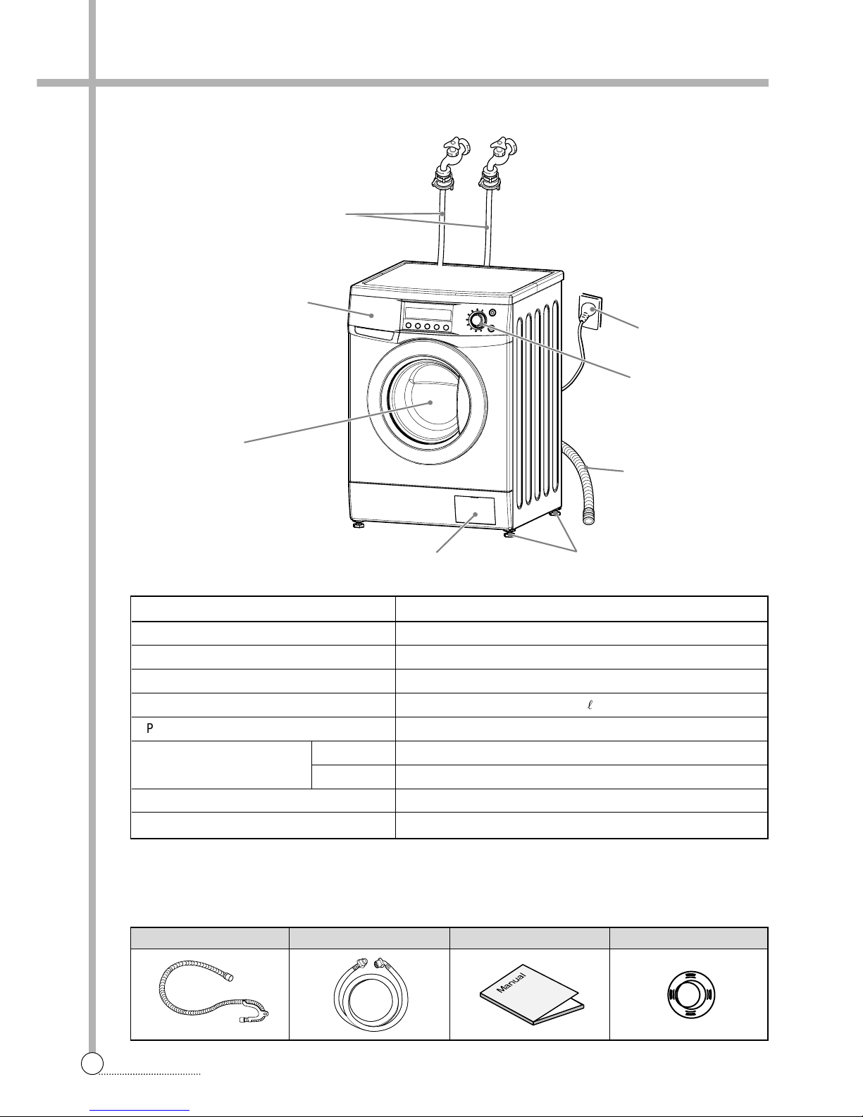
1. SPECIFICATIONS
2
SPECIFICATIONS
HOT
(OPTION)
COLD
■
Accessories
■
FD141X SERIES
Hose drain Inlet hose Manual Cap holder(3EA)
POWER SOURCE 220-240V, 50/60Hz
DiMENSION (WXDXH) 595mm x 540mm x 850mm
WEIGHT 58 kg
WATER CONSUMPTION 56.1
l
POWER CONSUMPTION 2200W
MAXIMUM MASS WASH 7 kg
OF TEXTILE SPIN 7 kg
WASHER TYPE DRUM TYPE (FRONT LOADING WASHING MACHINE)
OPERATING WATER PRESSURE 0.3 ~ 8kgf/cm2(29.4 ~ 784kPa)
DWD-FD1411 / 1412
MODEL
ADJUSTABLE LEG
CONTROL PANEL
DOOR
DETERGENT CASE
INLET HOSE
LOWER COVER
POWER CORD
HOSE DRAIN
Page 4

3
SPECIFICATIONS
HOT
(OPTION)
COLD
■
Accessories
■
FD143X SERIES
Hose drain Inlet hose Manual Cap holder(3EA)
POWER SOURCE 220-240V, 50/60Hz
DiMENSION (WXDXH) 595mm x 540mm x 850mm
WEIGHT 58 kg
WATER CONSUMPTION 56.1
l
POWER CONSUMPTION 2200W
MAXIMUM MASS WASH 7 kg
OF TEXTILE SPIN 7 kg
WASHER TYPE DRUM TYPE (FRONT LOADING WASHING MACHINE)
OPERATING WATER PRESSURE 0.3 ~ 8kgf/cm2(29.4 ~ 784kPa)
DWD-FD1411/1412/1413, DWD-FD1421/1422/1423, DWD-FD1431/1432/1433
MODEL
ADJUSTABLE LEG
CONTROL PANEL
DOOR
DETERGENT CASE
INLET HOSE
LOWER COVER
POWER CORD
HOSE DRAIN
Page 5
2. INSTALLATION
4
INSTALLATION
■ Transit bolts
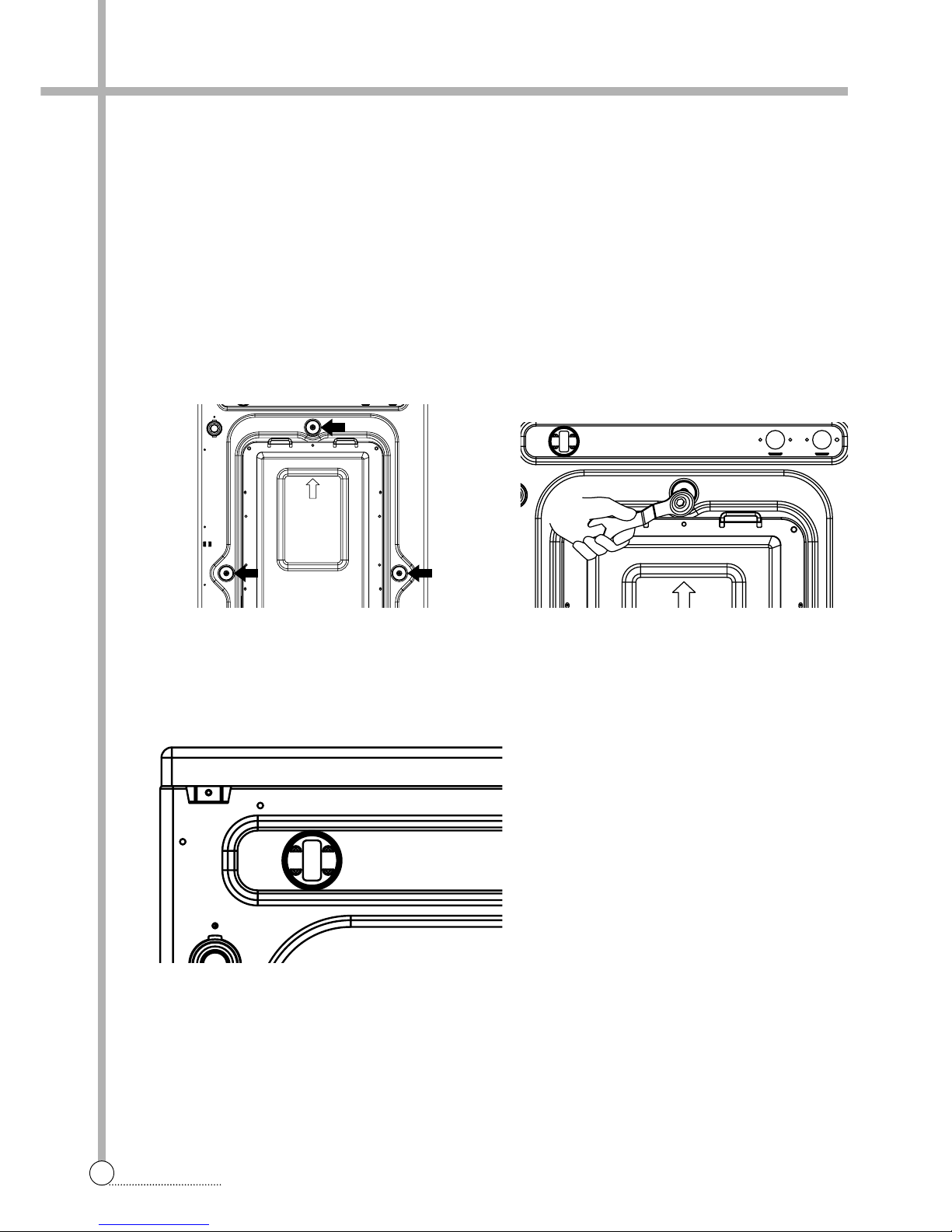
The appliance is fitted with transit bolts to prevent internal damage during transport.
■ Removing transit bolts
1. To prevent internal damage during trnasport, the
special 3 bolts are locked. Before operating the
washer, remove the bolts along with the rubber
bungs.
• If they are not removed, it may cause heavy
vibration, noise and malfunction.
2. Unscrew the 3 bolts with the 10mm hex wrench
or spanner or cross-tip screwdriver.
Keep the 3 bolts for a later time.
• When the appliznce is transported, transit bolts
will be re-used.
3. Close the holes with the caps supplied.
■ Transit bolts
The appliance is fitted with transit bolts to prevent internal damage during transport.
■ Removing transit bolts
Page 6
5
INSTALLATION
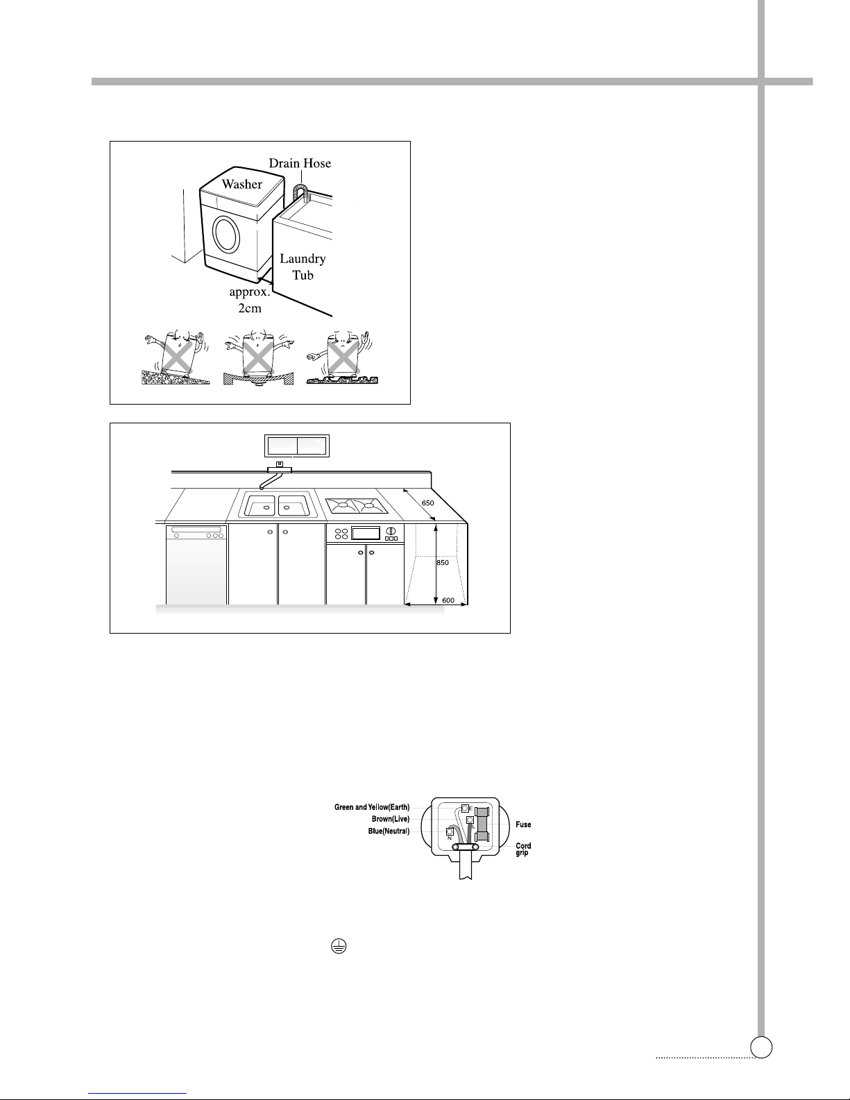
■ Installation place requirement
■ BS Plug Safety Details (For U.K. User)
Level floor :
Allowable slope under entire washer is 1°
Power outlet :
Must be with 1,5 meters of entire side of location of
washer. Do not overload the outlet with more than
one appliance.
Additional Clearance :
For wall, door and floor modeling is required.
(10cm : rear / 2cm : right & left side)
Do not place or store laundry products on top of
washer at any times.
They can damage the finish or controls.
As the colours of the wires in the mains lead of this apparatus may not correspond with the coloured markings
identifying the terminals in your plug, proceed as follows:
The wire which is coloured Green and Yellow must be connected to the terminal in the plug which is marked
with the letter E or by the earth symbol or coloured Green or Green and Yellow.
The wire which is coloured Blue must be connected to the terminal witch is marked with the letter N or coloured Black.
The wire which is coloured Brown must be connected to the terminal witch is marked with the letter N or
coloured Red.
If a 13 amp (BS 1363) plug is used, fit a 13amp BS 1362 fuse.
IMPORT ANT
THE WIRES IN THIS MAINS LEAD ARE COLOURED IN ACCORDANCE WITH THE FOLLOWING CODE:
GREEN AND YELLOW : EARTH
BLUE : NEUTRAL
BROWN : LIVE
This appliance must be earthed
Page 7
6
INSTALLATION
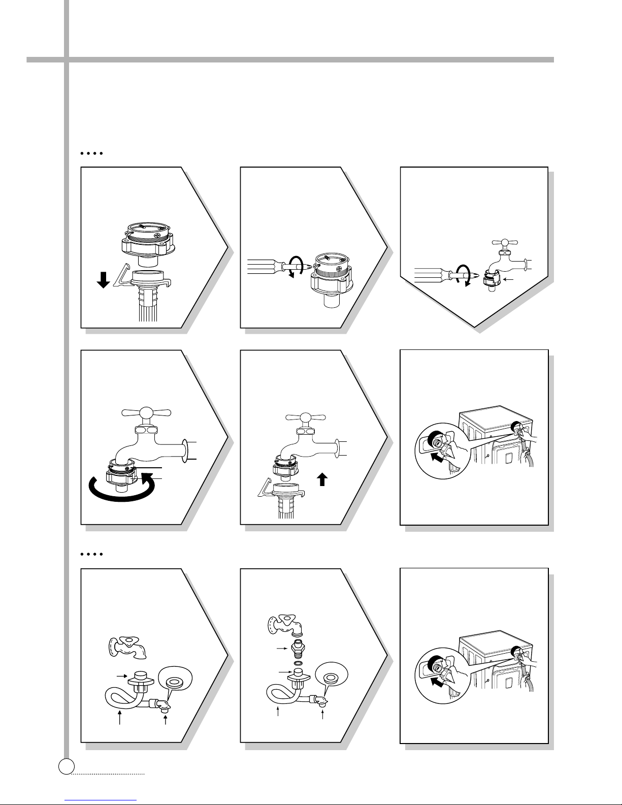
FOR ORDINARY TAP
6 Connect the inlet hose
adapter of the hose to the
water inlet of the washer by
turning it clockwise to be fixed
tightly.
• Please check the rubber packing present inside the inlet hose
adapter of the hose.
1 Pull down the collar
of the inlet hose to
separate it from the
water tap adapter.
2 Loosen the four
screws properly in
order to fit into
water tap.
4 Remove the tape,
and screw connector
B into connect A
tightly.
5 Conect the inlet hose
to the water tap
adapter by pulling
down the collar of the
hose end.
3 Fit the water tap adapter into
the water tap and tighten the
four screws evenly while push-
ing up the adapter so that the
rubber packing can stick to the
water tap tightly.
■ Connecting inlet hose
In using only one water tap or in case of only one water inlet valve, connect the inlet hose to the cold water inlet valve.
Option : Be careful not to confuse hot water inlet and cold water inlet.
FOR SCREW-SHAPED T A P
3
Connect the inlet hose adapter
to the water inlet of the washer
and turn it to be fixed.
• Check the packing in the inlet.
1 Conect the inlet hose
to the water tap
adapter by pulling
down the collar of the
hose end.
2
Conect the connectorinlet supplied if
necessary .
Inlet Hose
Connector D
Rubber
Packing
Connector C
Connector
Inlet
Rubber
Packing
Connector D
Connector C
Hose
TAPE
Connector B
Connector A
Page 8
7
INSTALLATION
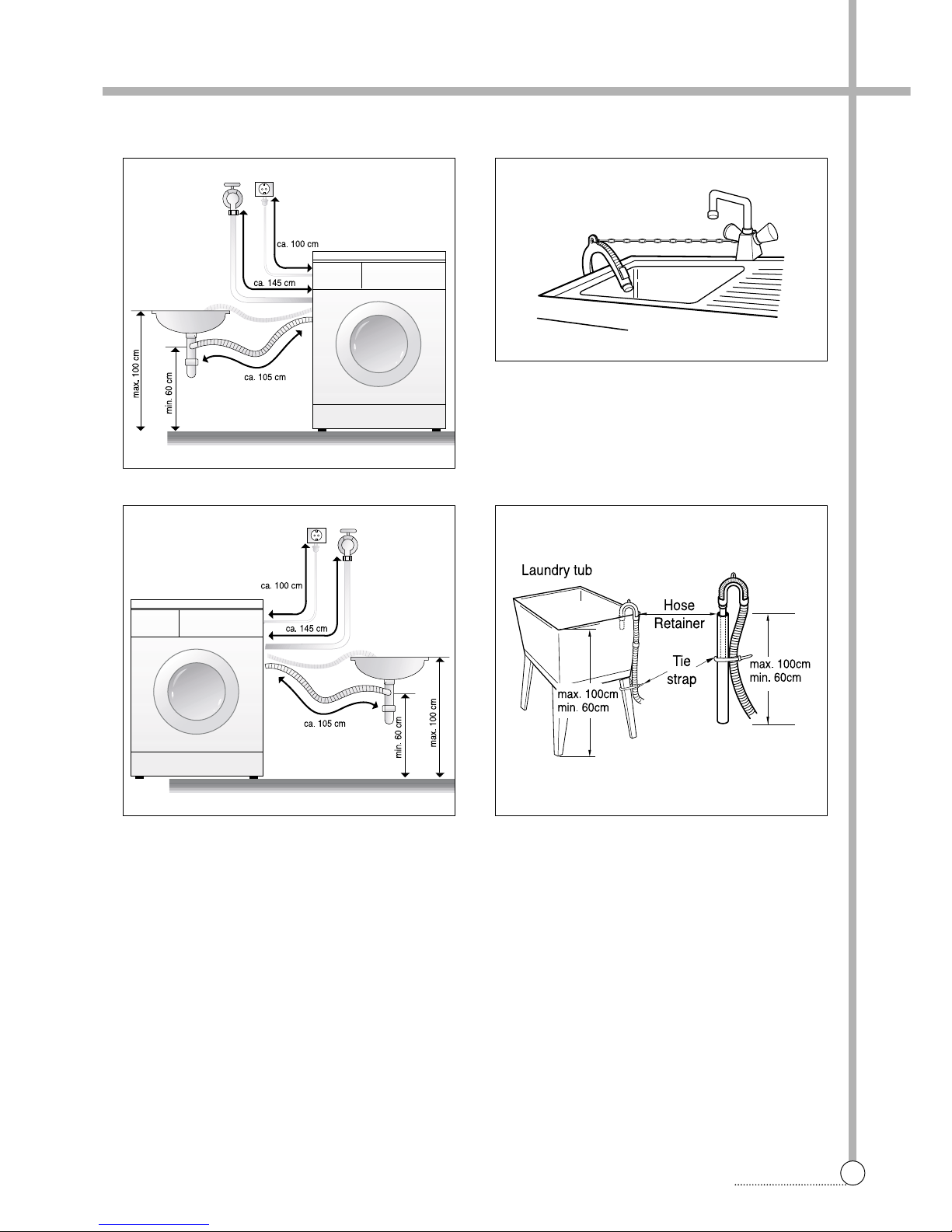
■ Installation of drain hose
• When installing the drain hose in sink, secure
it tightly with a string.
• Proper securing of the drain hose will protect the
floor from damage due to water leakage.
• The drain hose should not be placed higher than
100cm above the floor.
• Proper securing of the drain hose will protect the
floor from damage due to water leakage.
• When the drain hose is too long, do not force
back in to the washer. This will cause abnormal noise.
■ Installation of drain hose
Page 9
8
INSTALLATION
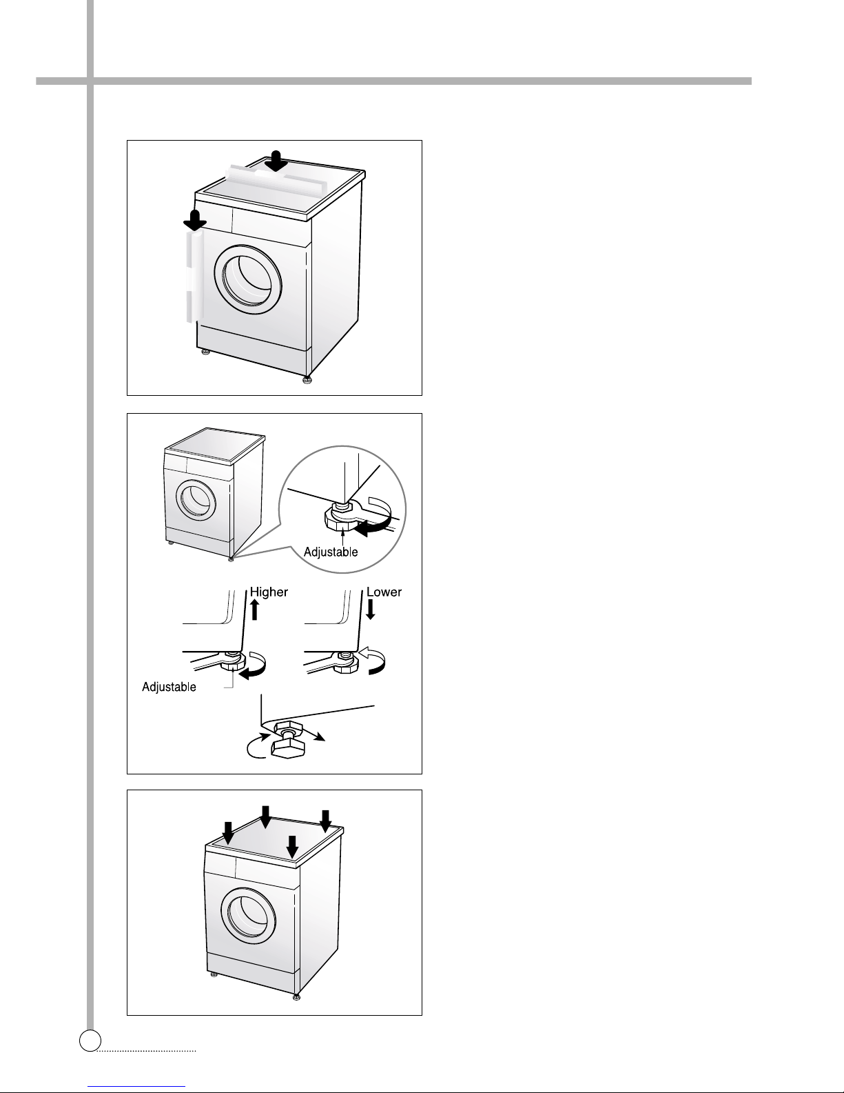
■ Level adjustment
1. The level adjustment of the washing machine prevents excessive noise and vibration.
Install the washing machine on a solid and even
floor surface, if possible, in a corner of the room.
Note: the wooden floor may cause excessive
vibration.
2. If the floor is uneven, adjust the adjustable leg as
the following.
(Do not insert pieces of wood etc. under legs.)
• Please check whether there is any gap between
four adjustable legs and the floor.
• Turn adjustable legs by the enclosed spanner in
order to adjust the level of the washing machine.
• Make it sure that there is no swaying of the washing machine and check that the washing
machine is even completely. (use a spirit level)
• After the level adjustment is finished, turn fixing
nuts up tightly so that the washing machine
maintains the adjustment.
leg
leg
Fixing Nut
❈ Diagonal Check
When pushing down the edges of the washing
machine top plate diagonally, the machine should
not move up and down at all.
(Pllease, check both of two directions)
If machine rocks when pushing the machine top
plate diagonally , adjust legs again.
Page 10
3. MAINTENANCE
9
MAINTENANCE
❈ Before cleaning the washer interior, unplug the electrical power cord avoid electrical shock hazards.
■ Cleaning your washer
1. Exterior
Proper care of your washer can extend its life.
The outside of the machine can be cleaned with warm water and a neutral non abrasive houshold detergent.
Immediately wipe off any spills. Wipe with damp cloth.
Try not to hit surface with sharp objects.
• Do not use methylated spirits, diluents or similar products.
2. Interior
Dry around the washer door opening, flexible gasket and door glass.
Run washer through a complete cycle using hot water.
Repeat process if necessary.
• Remove hard water deposits using only cleaners labeled as washer safe.
■ Cold condition
If the washer is stored in an area where freezing may occur or moved in freezing temperature,
follow these instructions to prevent damage to the washer.
1. Turn off water supply tap.
2. Disconnect hoses from water supply and drain water from hoses.
3. Plug electrical cord into a properly grounded electrical outlet.
4. Add 1gallon(3.8L) of nontoxic recreational vehicle(RV) antifreeze into empty wash drum.
Close the door.
5. Set spin cycle and let washer spin for 1minute to drain out all water.
6. Unplug eletrical power cord, dry the drum interior, and close the door .
7. Remove detergent case and dry excessive water from the compartments.
8. Store washer in an upright position.
9. To remove antifreeze from washer after storage, run empty washer through a complete cycle using detergent. Do
not add wash load.
Page 11

10
MAINTENANCE
■ Cleaning the water inlet filter
• "IE" error message will blink on the control panel when water does not enter the detergent drawer.
• If your water is very hard or contains traces of lime deposit, the water inlet filter may become clogged.
• It is therefore a good idea to clean it from time to time.
■ Cleaning the drain pump filter
• The drain filter collects threads and small objects left in the laundry .
• Check regularly that the filter is clean to ensure smooth running of your machine.
CAUTION Be careful when draining if the water is hot.
1. Turn off the
water tap.
2. Unscrew the
water inlet
hose.
3. Clean the filter
using a had
bristle brush.
4. Tighten up the
inlet hose.
1. Open the lower cover(1) by
using a coin. Turn the cap
hose(2) to pull out the hose.
Pull out the hose maximally.
(About 13~14cm.)
2.
Unplug the cap hose(2), allowing
the water to flow out. At this time use
a vessel to prevent water flowing on
to the floor. When water does not
flow any more, turn the pump
filter(3) open to the left.
3. Remove any foreign material
from the pump filter(3). After
cleaning, turn the pump filter
clockwise and insert the cap
hose(2) to the original place.
Close the lower cover.
1
100
2
3
about
13~14cm
2
3
about
13~14cm
■ Cleaning the water inlet filter
• "IE" error message will blink on the control panel when water does not enter the detergent drawer.
• If your water is very hard or contains traces of lime deposit, the water inlet filter may become clogged.
• It is therefore a good idea to clean it from time to time.
Page 12
11
MAINTENANCE
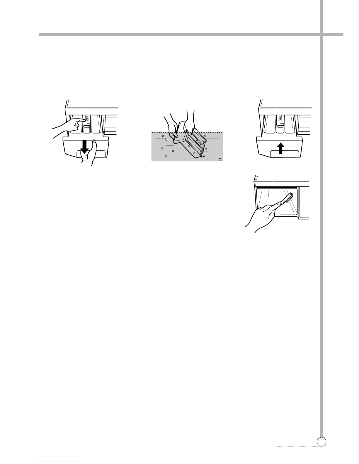
■ Cleaning the detergent case
❈After a while detergents and fabric softeners leave a deposit in the detergent case.
• It should be cleaned from time to time with a jet of running water.
•If necessary it can be removed completely from the machine by pressing the catch downwards and by pulling it out.
• To facilitate cleanling, the upper part of the fabric softener compartment can be removed.
Inlet box recess
❈Detergent can also accumulate inside the recess which should be cleaned
occasionally with an old toothbrush.
• Once you have finished cleaning, replace the detergent case and run a rinse
cycle without laundry.
MAX
max
MAX
max
■ Cleaning the washing drum
• If you live in a hard water area, limescale may continuously build up in places where it cannot be seen and thus
not easily removed.
• Over time the build up of scale clogs appliances, and if it is not kept in check these may have to be replaced.
• Although the washing drum is made of stainless steel, specks of rust can be caused by small metal articles (paper
clips, safety pins) which have been left in the drum.
• The washing drum should be cleaned from time to time.
• If you use descaling agents, dyes or bleaches, make sure they are suitable for washing machine use.
❈Descaler may contain chemicals that may damage part of your washing machine.
❈Remove any spots with a stainless steel cleaning agent.
❈Never use steel wool.
■ Cleaning the detergent case
❈After a while detergents and fabric softeners leave a deposit in the detergent case.
• It should be cleaned from time to time with a jet of running water.
•If necessary it can be removed completely from the machine by pressing the catch downwards and by pulling it out.
• To facilitate cleanling, the upper part of the fabric softener compartment can be removed.
Page 13
12
DIRECTION FOR DISASSABLY
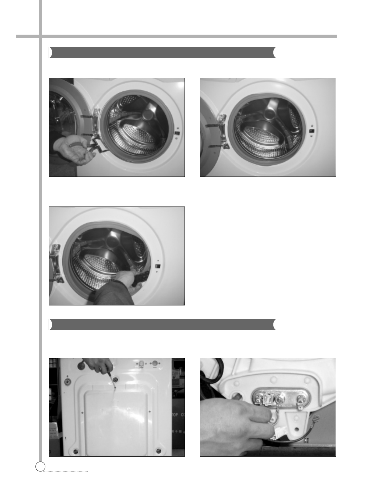
DOOR LOCK SWITCH
1) Open the door and remove the gaske clamp. 2) Remove the gasket from the front cabinet.
HEATER AND THERMISTOR
1) Remove five screws on the COVER B and separate
the COVER B from washing machine.
2) Remove the connectors of the HEATER.
3) Remove two screws, and remove the door lock
switch.
4. DIRECTION FOR DISASSEMBLY
Page 14
13
DIRECTION FOR DISASSABLY
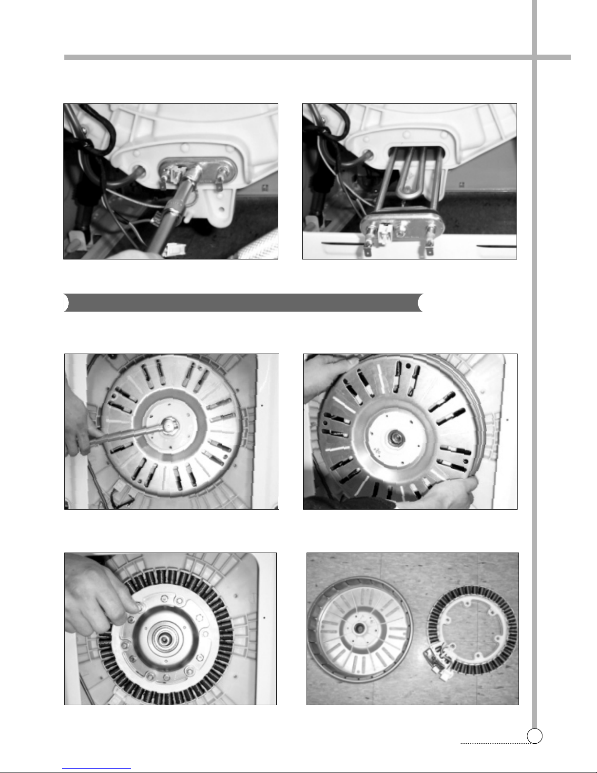
3) Remove the nut using the 10mm hex wrench and
remove the earth terminal from the HEATER.
4) Loose the nut of the HEATER and pull out the
HEA TER.
BLDC MOTOR
1) Remove the nut using the 17mm hex wrench. 2) Pull out the ROTOR.
3) Remove six screws using the 10mm hex wrench and
connectors from the STATOR.
4) Separate the ST ATOR from the TUB.
Page 15
14
DIRECTION FOR DISASSABLY
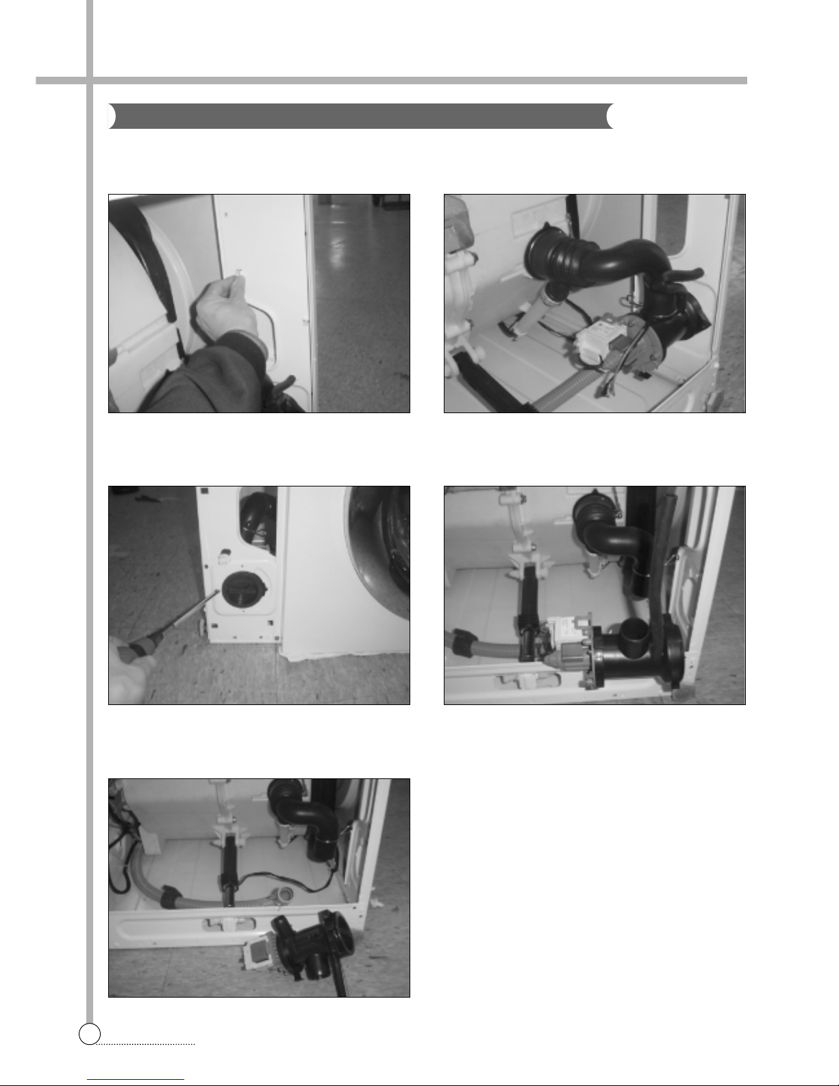
DRAIN PUMP
1) Lay the right side of the washer on the floor, and
remove the lower panel by pressing six sanp fits.
2) Remove connectors.
3) Remove the screw, and remove the drain pump from
the lower frame.
4) Remove the drain hose.
5) Remove the inner drain hose, and remove the drain
pump.
Page 16
15
EXPLODE VIEW AND PARTS LIST
5. EXPLODE VIEW AND P ARTS LIST
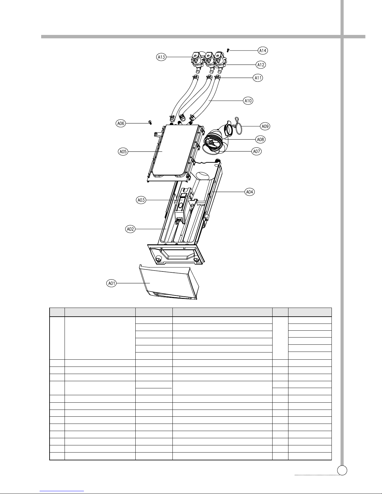
■ BOX INLET AS
No. P ART NAME P ART CODE SPECIFICA TION Q'TY REMARK
3612608700 ABS DWD-FD1411(2)
3612608710 ABS+SPRAY DWD-FD1413
A01 HANDLE CASE 3612608900 ABS DWD-FD1421(2)
3612608910 ABS+SPRAY 1 DWD-FD1423
3612609700 ABS DWD-FD1431(2)
3612609710 ABS+SPRAY DWD-FD1433
A02 CASE DETERGENT 361 1140300 PP 1
A03 CAP SOFTENER 3610916600 PP 1
A04 BOX INLET 3610526500 PP 1
A05 NOZZLE AS
3618103510
NOZZLE TOP + NOZZLE UNDER
1COLD
3618103500 1 COLD+HOT
A06 SCREW T APPING 712240201 1 T2S TRS 4X20 MFZN 1
A07 CLAMP AS 361 1203200 ID=60,WIRE+GUIDE+BOL T+NUT 1
A08 HOSE INLET 3613267200 EPDM U-TRAP 1
A09 CLAMP HOSE I 3611201400 HSW3, D2.6, MFZN, ID=38 1
A10 HOSE WATER SUPPLY 3613270900 EPDM,ID=9.5,OD=14.5,L=225 2(3) COLD(HOT)
A1 1 CLAMP HOSE 361 1205800 ID=13.8, W=10.0, T=0.9 4(6) COLD(HOT)
A12 V ALVE INLET AS 3615416820 220-240V 60HZ VDE BITRON 2WAY 1 COLD
A13 V ALVE INLET AS 3615416720 220-240V 60HZ VDE BITRON 1WAY 1 HOT
A14 SCREW T APTITE 7272400811 TT3 TRS 4X8 MFZN 2(4) COLD(HOT)
Page 17
16
EXPLODE VIEW AND PARTS LIST
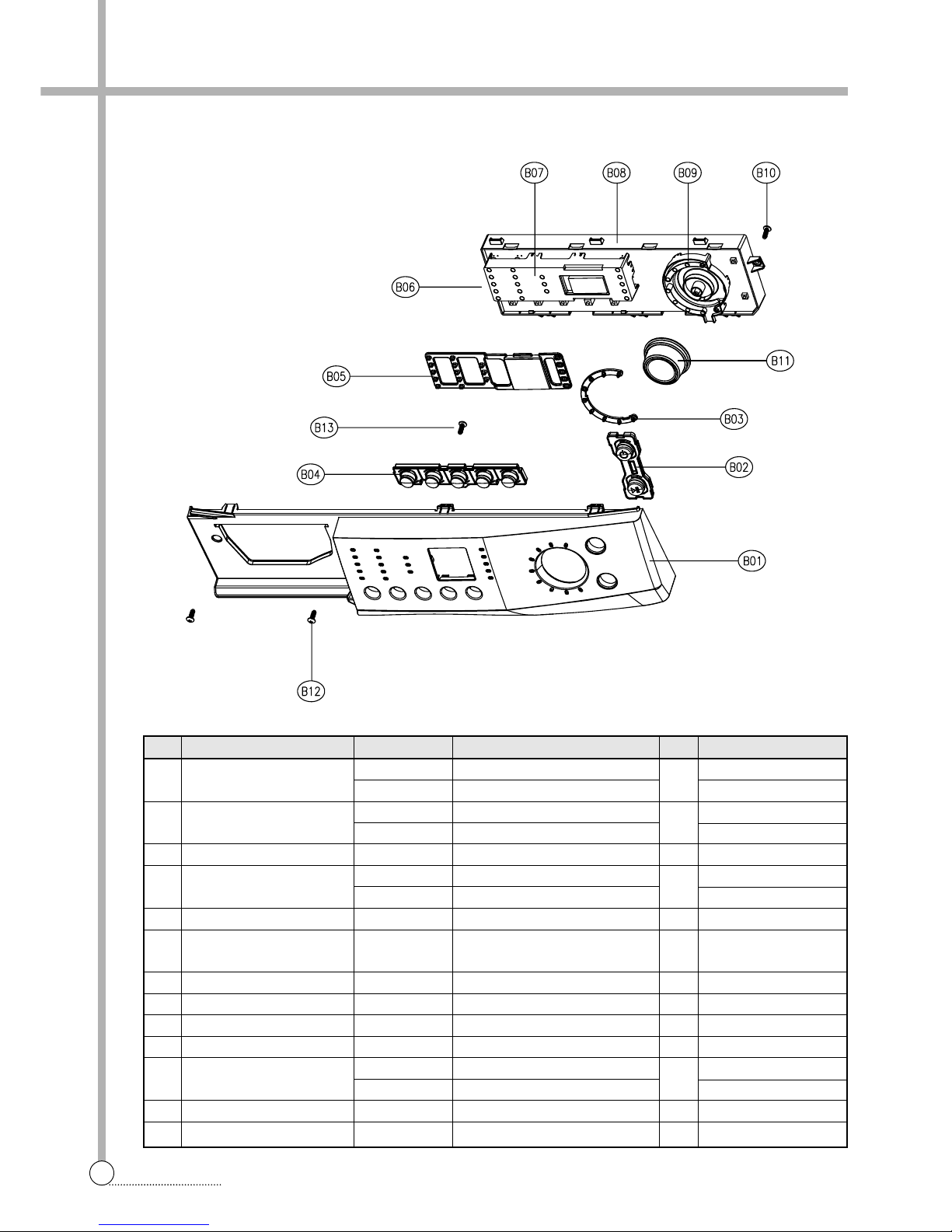
■ PANEL FRONT AS (DWD-FD141X SERIES)
No. P ART NAME P ART CODE SPECIFICA TION Q'TY REMARK
B01 P ANEL F
3814282700 ABS
1
DWD-FD141 1(2)
3814282710 SILVER SPRAY DWD-FD1413
B02 BUTTON POWER
3616603600 ABS
1
DWD-FD141 1
3616603620 ABS + AL COATING DWD-FD1412(3)
B03 WINDOW DIAL 3615503100 ABS-TR 1
B04 BUTTON SELECT
3616603500 ABS
1
DWD-FD141 1
3616603520 ABS + AL COATING DWD-FD1412(3)
B05 WINDOW DISPLA Y AS 3615503020 ABS-TR + STICKER 1
B06 PCB AS PRPSSWFD-- DWD-FD14 SERIES 1
Refer to Detailed
Part Code of PCB AS
B07 HOLDER LED 3613049600 ABS 1
B08 CASE PCB 3611143100 HIPS 1
B09 HOLDER DIAL 3613049700 ABS 1
B10 SCREW T APPING 712240161 1 T2S TRS 4x16 MFZN 4
B1 1 KNOB DIAL AS
3613405000 ABS
1
DWD-FD141 1(2)
3613405010 SPRAY DWD-FD1413
B12 SCREW T APPING 7122401608 T2S TRS 4x16 SUS 2
B13 SCREW T APPING 712240121 1 T2S TRS 4x12 MFZN 2
Page 18
17
EXPLODE VIEW AND PARTS LIST
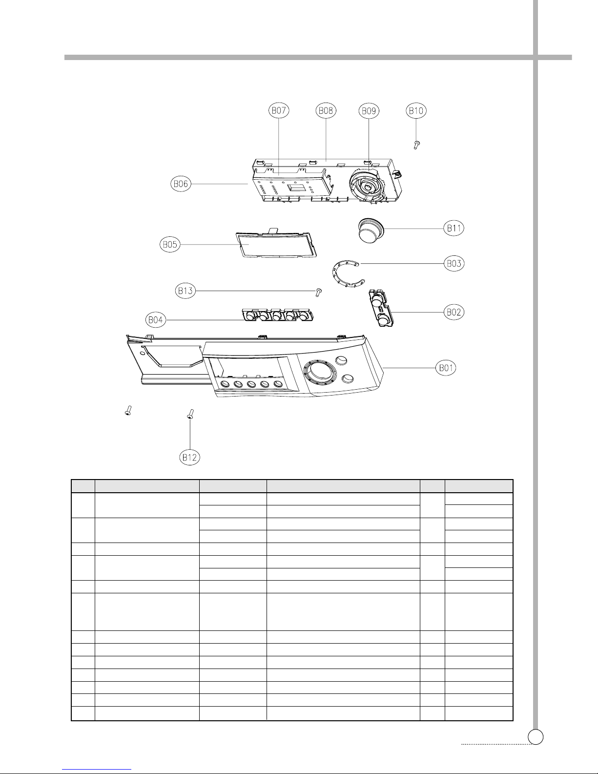
■ PANEL FRONT AS (DWD-FD142X SERIES)
No. P ART NAME P ART CODE SPECIFICATION Q'TY REMARK
B01 P ANEL F
3614284500 ABS
1
DWD-FD1421(2)
3614284510 SIL VER SPRAY DWD-FD1423
B02 BUTTON POWER
3616604200 ABS
1
DWD-FD1421
3616604210 ABS+AL COA TING DWD-FD1422(3)
B03 WINDOW DIAL 3615503400 ABS 1
B04 BUTTON SELECT
3616604100 ABS 1 DWD-FD1421
36166041 10 ABS+AL COATING 1 DWD-FD1422(3)
B05 WINDOW LED 3615503300 ABS
Refer to
B06 PCB AS PRPSSWFD-- DWD-FD14 SERIES 1 Detailed Part
Code of PCB AS
B07 HOLDER LED 3613050500 ABS 1
B08 CASE PCB 361 1140200 HIPS 1
B09 HOLDER DIAL 3613050600 ABS 1
B10 SCREW T APPING 7122401611 T2S TRS 4x16 MFZN 4
B1 1 KNOB DIAL 3613405110 ABS+SPRAY 1
B12 SCREW T APPING 7122401608 T2S TRS 4x16 SUS 2
B13 SCREW T APPING 7122401211 T2S TRS 4x12 MFZN 2
Page 19
18
EXPLODE VIEW AND PARTS LIST
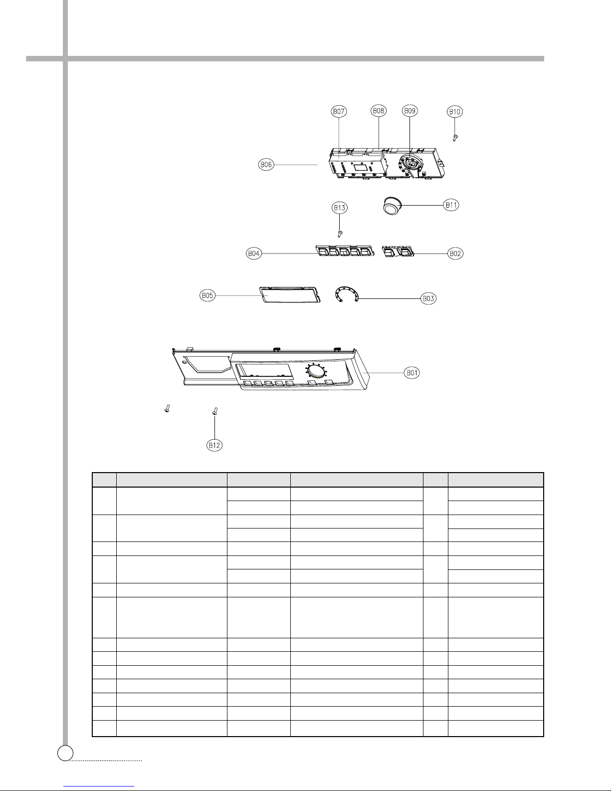
■ PANEL FRONT AS (DWD-FD141X SERIES)
No. P ART NAME P ART CODE SPECIFICA TION Q'TY REMARK
B01 P ANEL F
3614285800 ABS 1 DWD-FD1431(2)
3614285810 ABS + SPRAY DWD-FD1433
B02 BUTTON POWER
3616635300 ABS 1 DWD-FD1431
3616635310 ABS + SPRAY DWD-FD1432(3)
B03 WINDOW DIAL 3615504200 ABS-TR 1
B04 BUTTON SELECT
3616635400 ABS 1 DWD-FD1431
3616635410 ABS + SPRAY DWD-FD1432(3)
B05 WINDOW DISPLA Y 3615504300 ABS-TR 1
Refer to
B06 PCB AS PRPSSWFD-- DWD-FD14 SERIES 1 Detailed Part
Code of PCB AS
B07 HOLDER DISPLA Y 3613051700 HIPS 1
B08 CASE PCB 3611143200 HIPS 1
B09 HOLDER DIAL 3613051500 HIPS 1
B10 SCREW T APPING 712240161 1 T2S TRS 4°ø16 MFZN 4
B1 1 KNOB DIAL 3613405210 ABS+SPRAY 1
B12 SCREW T APPING 7122401608 T2S TRS 4°ø16 SUS 2
B13 SCREW T APPING 712240121 1 T2S TRS 4°ø12 MFZN 2
Page 20
19
EXPLODE VIEW AND PARTS LIST
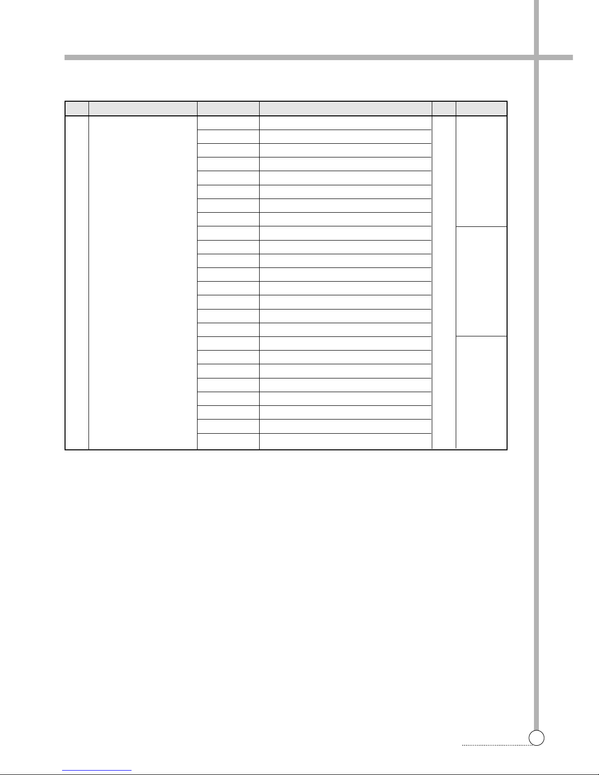
■ Detailed Part Code of PCB AS
No. P ART NAME P ART CODE SPECIFICA TION Q'TY REMARK
B06 PCB AS PRPSSWFD07 DWD-FD141’s, EC, COLD V/V, NON-BB 1 1st PANEL
PRPSSWFD08 DWD-FD141’s, EC, COLD V/V, BB
PRPSSWFD09 DWD-FD141’s, EC, HOT V/V, NON-BB
PRPSSWFD10 DWD-FD141’s, EC, HOT V/V, BB
PRPSSWFD1 1 DWD-FD141’s, NON-EC, COLD V/V, NON-BB
PRPSSWFD12 DWD-FD141’s, NON-EC, COLD V/V, BB
PRPSSWFD13 DWD-FD141’s, NON-EC, HOT V/V, NON-BB
PRPSSWFD14 DWD-FD141’s, NON-EC, HOT V/V, BB
PRPSSWFD15 DWD-FD143’s, NON-EC, HOT V/V, BB 2nd PANEL
PRPSSWFD30 DWD-FD143’s, NON-EC, HOT V/V, NON-BB
PRPSSWFD31 DWD-FD143’s, NON-EC, COLD V/V, BB
PRPSSWFD32 DWD-FD143’s, NON-EC, COLD V/V, NON-BB
PRPSSWFD33 DWD-FD143’s, EC, HOT V/V, BB
PRPSSWFD34 DWD-FD143’s, EC, HOT V/V, NON-BB
PRPSSWFD35 DWD-FD143’s, EC, COLD V/V, BB
PRPSSWFD36 DWD-FD143’s, EC, COLD V/V, NON-BB
PRPSSWFD50 DWD-FD142’s, NON-EC, HOT V/V, BB 3rd PANEL
PRPSSWFD51 DWD-FD142’s, NON-EC, HOT V/V, NON-BB
PRPSSWFD52 DWD-FD142’s, NON-EC, COLD V/V, BB
PRPSSWFD53 DWD-FD142’s, NON-EC, COLD V/V, NON-BB
PRPSSWFD54 DWD-FD142’s, EC, HOT V/V, BB
PRPSSWFD55 DWD-FD142’s, EC, HOT V/V, NON-BB
PRPSSWFD56 DWD-FD142’s, EC, COLD V/V, BB
PRPSSWFD57 DWD-FD142’s, EC, COLD V/V, NON-BB
Page 21
20
EXPLODE VIEW AND PARTS LIST
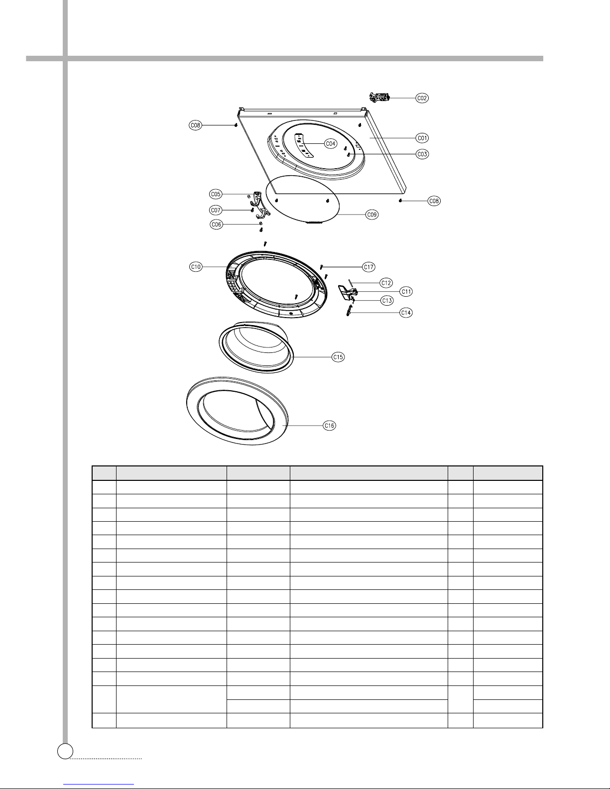
■ CABINET FRONT AS
No. PART NAME P ART CODE SPECIFICA TION Q'TY REMARK
C01 CABINET FRONT 3610811220 SECD 0.7T 1
C02 SWITCH DOOR LOCK 3619047100
DL-LC BITRON_3P 250V 16A BI-MET AL
1
C03 SCREW TAPPING 7122401208 T2S TRS 4X12 SUS 2
C04 PLATE HINGE SUPPORT 3614531900 SGCC T1.6 1
C05 HINGE DOOR 3612902800 ZNDC 1
C06 CAP HINGE DOOR 3610916500 POM 2
C07 SCREW TAPPING 3616030000 F/L BOL T(SE) 5*12 SUS 2
C08 SCREW TAPPING 3616029950 TTS"S" HEX F/L 4*8 6
C09 CLAMP DOOR AS 361 1204800 HSWR D=1.4 1
C10 FRAME DOOR I 3612205200 PP 1
C1 1 HANDLE DOOR 3612608600 ABS 1
C12 PIN HANDLE 3618200200 SUS304, D3, L48 1
C13 SPRING HOOK 36151 14600 SUS D1.4 1
C14 HOOK DOOR 3613100700 ZNDC 1
C15 DOOR GLASS 361A1 10700 GLASS PI300 1
C16 FRAME DOOR O
3612205100 ABS
1
DWD-FD141 1
3612205140 CR6+ GILDING DWD-FD1412
C17 SCREW TAPPING 7115402008 T1S FL T 4*20 SUS 6
Page 22
21
EXPLODE VIEW AND PARTS LIST
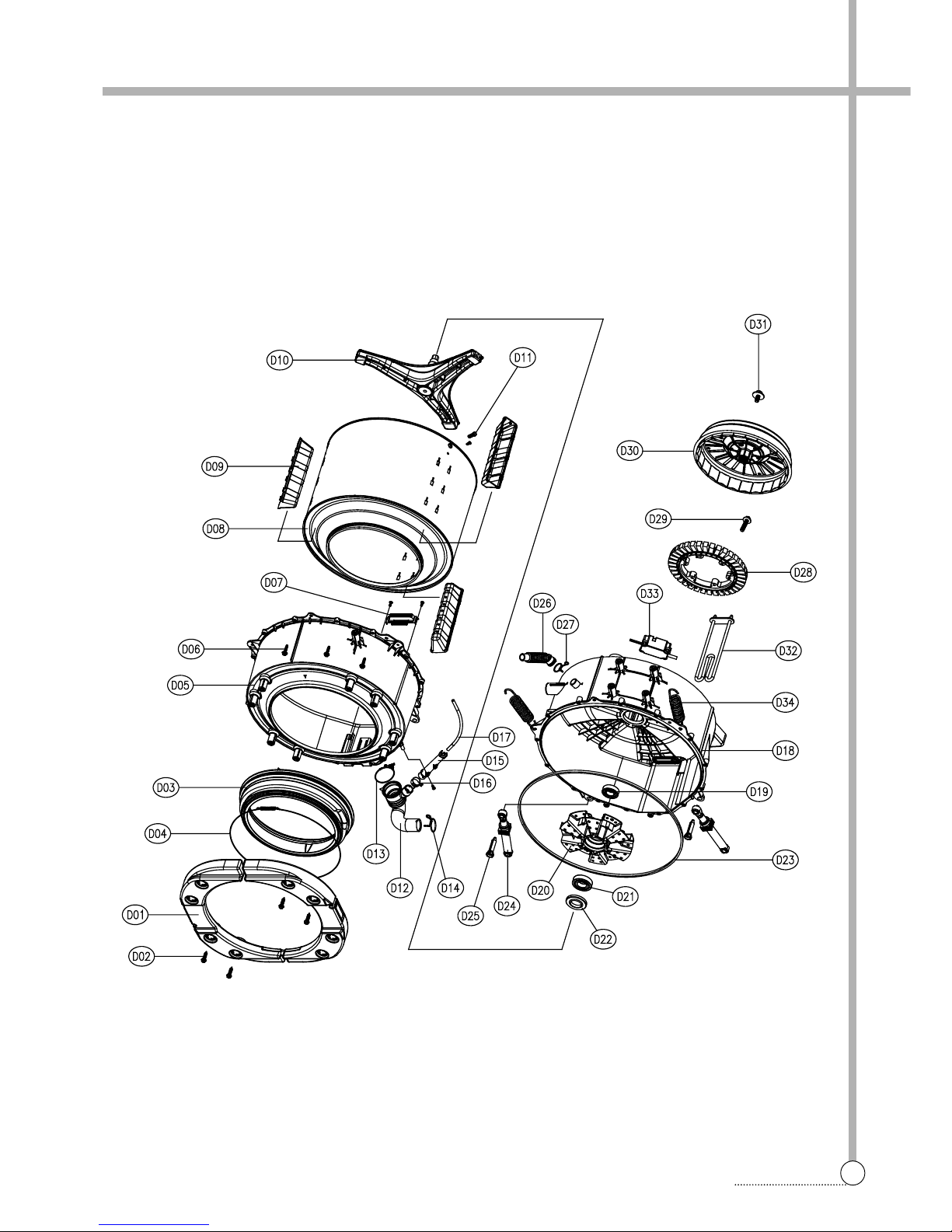
■ TUB ASS’Y
Page 23
22
EXPLODE VIEW AND PARTS LIST
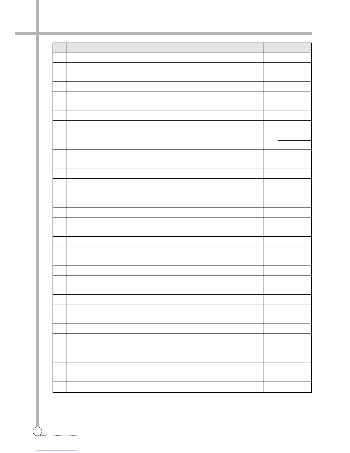
No. PART NAME PART CODE SPECIFICATION Q'TY REMARK
D01 BALANCER WEIGHT F L/R 3616106320 FRONT, 5.5kg 2
D02
SPECIAL SCREW(BALANCER)
3616029400 SWCH 8.5X30 8
D03 GASKET 3612321400 EPDM 1
D04 CLAMP GASKET AS 3611204500 HSWR D=1.8 1
D05 TUB FRONT 3618821010 FRPP FH7304GM 1
D06 SPECIAL SCREW(TUB) 3616029800 SWCH 6.5X30 14
D07 FIXTURE HEA TER 3612007300 SUS 0.7T 440°ø45 1
D08 DRUM SUB AS 3617004001 SUS 0.5T 1
D09 LIFTER WASH
361A400400 PP
3
361A400410 NANO OPTION
D10 SPIDER AS 361A300500 ALDC+SM45C 1
D1 1 SPECIAL SCREW(SPIDER) 3616029500 SUS430 8x25 3
D12 HOSE DRAIN 3613267300 EPDM 1
D13 CLAMP AS 3611203200 ID=60,WIRE+GUIDE+BOLT+NUT 1
D14 CLAMP HOSE I 361 1201400 HSW3, D2.6, MFZN, D=38 1
D15 AIR TRAP 361A500101 PP 1
D16 CLAMP HOSE 3611204700 D27 1
D17 HOSE AIR 3613268600 ID=4, OD=8, L=700 1
D18 TUB REAR 3618821110 FRPP FH7304GM 1
D19 BEARING OUTER 3616303200 6205Z FAG 1
D20 BEARING HOUSING 3616303300 ALDC 1
D21 BEARING INNER 3616303100 6206Z FAG 1
D22 WATER SEAL 361A600100 NBR 1
D23 GASKET TUB 3612321600 EPDM L=1675 1
D24 DAMPER FRICTION 361A700120 120N, AKS, ST=170-160, DL=197.5 2
D25 DAMPER PIN 361A700200 AKS, D=14.5 2
D26 HOSE VENT 3613267100 EPDM 1
D27 CLAMP HOSE 3611204700 D27 1
D28 UNIT ST ATOR BLDC 36189L4820 AL-16T 36SLOT 2SNESOR 1
D29 SPECIAL BOL T AS 3616029920 SWCH M8+SILOCK, 35MM 6
D30 UNIT ROTOR BLDC 36189L4910 MAGENT24 SERRATION 1
D31 SPECIAL BOL T AS 3616029600 SWCH M10xL30, F/L BOLT 1
D32 HEA TER W ASH 3612802410 230V 2KW IRCA 1
D33 UNIT BUBBLE PUMP 36189L4120 220-240V DBK-204DB 1 OPTION
D34 SPRING SUSPENSION 3615115300 D3.2, L164 2
Page 24
23
EXPLODE VIEW AND PARTS LIST
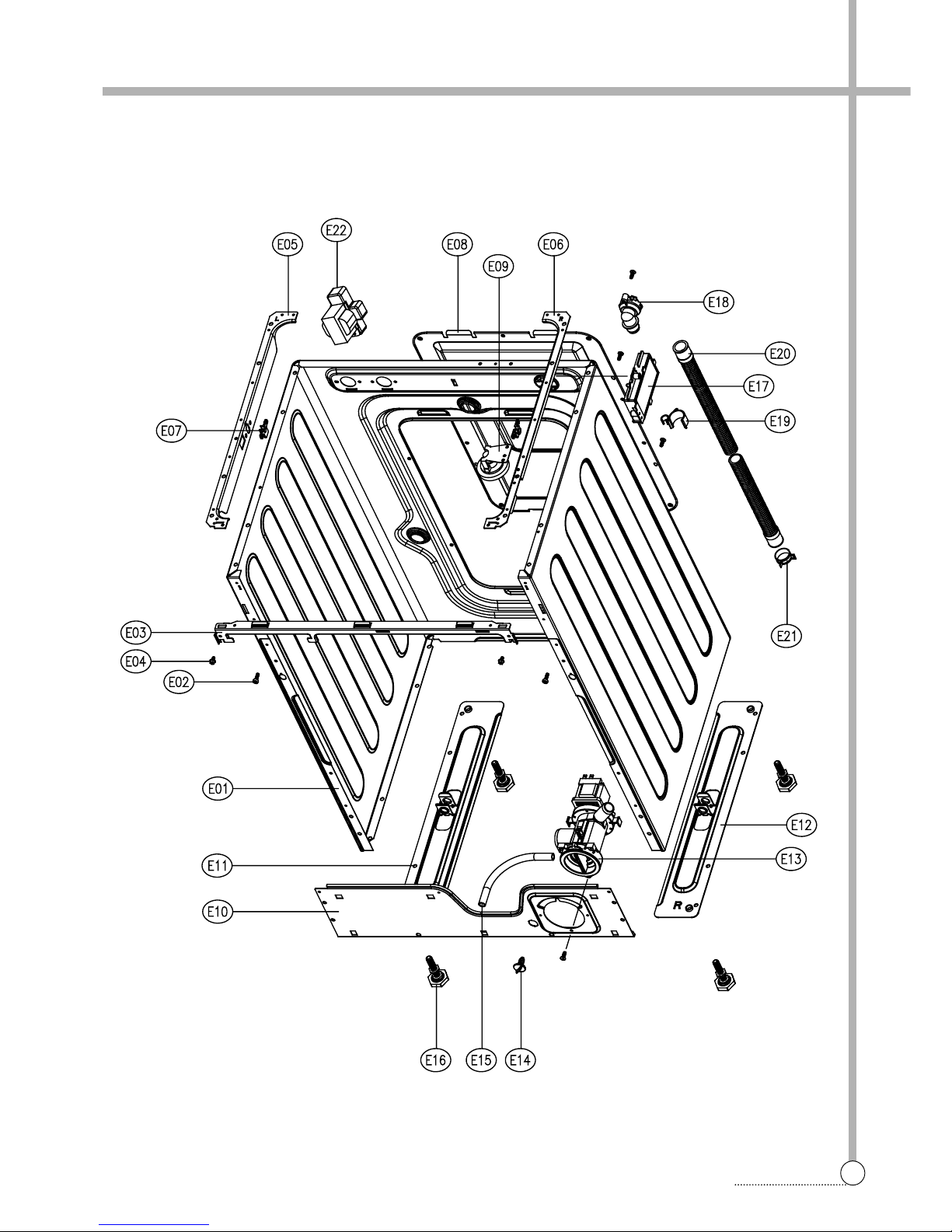
■ CABINET AS
Page 25
24
EXPLODE VIEW AND PARTS LIST
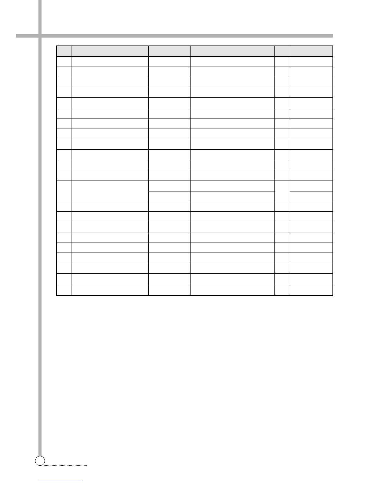
No. PART NAME P ART CODE SPECIFICA TION Q'TY REMARK
E01 CABINET 361081 1100 SGCC, T0.8, PAINTING 1
E02 SPECIAL SCREW 3616029100 M4x12.5, MACHINE 2
E03 FRAME UPPER 3612205800 SGCC T1.2 55X580 1
E04 SCREW T APPING 3616029950 TTS"S" HEX F/L 4X8 4
E05 FRAME TOP-L 3612205600 SGCC T1.6 52x500 1
E06 FRAME TOP-R 3612205700 SGCC T1.6 52x500 1
E07 STOPPER SPRING 3615202200 POM 2
E08 COVER B 3611427100 PP 1
E09 SENSOR PRESSURE 3614825300 5V DRUM DL-DW1 1 INLET 90 1
E10 FRAME LOWER 3612205500 SGCC T1.2 160X580 1
E1 1 BASE U-L 3610392200 SGCC T1.6 100x500 1
E12 BASE U-R 3610392300 SGCC T1.6 100x500 1
E13 UNIT DRAIN PUMP AS
36189L4F10 220-240V/50Hz B20-6 DRUM
1
36189L4E10 220V/60Hz B20-5 DRUM
E14 CAP WATER REMAIN 3610916800 PP 1
E15 HOSE WATER REMAIN 3613267800 EPDM, ID8.5, L200 1
E16 LEG ADJUST AS 3617703810 MFZN M10x1.25 + BUTYLE 4
E17 FIL TER LINE 3611909320 DWLF-K25 NON FUSE 1
E18 CUFF DRAIN HOSE 3616802500 PP 1
E19 GUIDE DRAIN HOSE 3612510400 PP 1
E20 HOSE DRAIN I AS 3613268400 L=870 1
E21 CLAMP HOSE 3611204700 D27 1
E22 REACTOR AS 3615800100 RT-046B 1 OPTION
Page 26
25
EXPLODE VIEW AND PARTS LIST
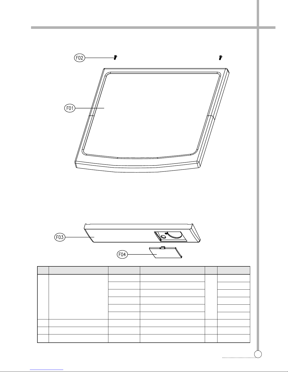
No. PART NAME PART CODE SPECIFICATION Q'TY REMARK
3614532900 ABS DWD-FD141 1(2)
3614532910 SILVER SPRAY DWD-FD1413
F01 PLA TE T AS
3614532920 ABS
1
DWD-FD1421(2)
3614532930 SILVER SPRAY DWD-FD1423
3614533300 ABS DWD-FD1431(2)
3614533310 SILVER SPRAY DWD-FD1433
F02 SCREW T APPING 7122401411 T2S TRS 4X14 MFZN 2
F03 PANEL LOWER 3614282801 HIPS 1
F04 COVER PUMP FIL TER 3611425801 HIPS 1
■ PLA TE T AS + PANEL LOWER AS
Page 27
26
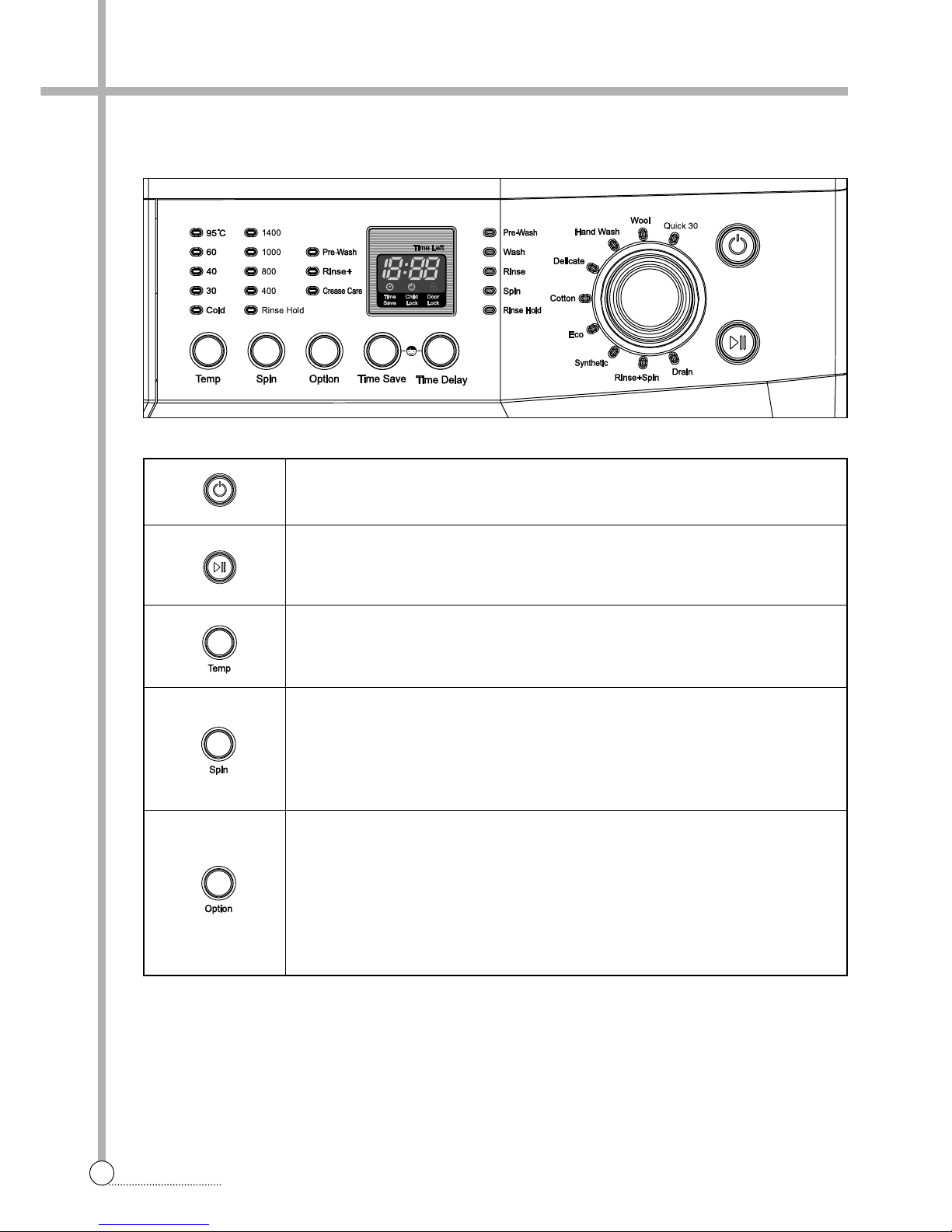
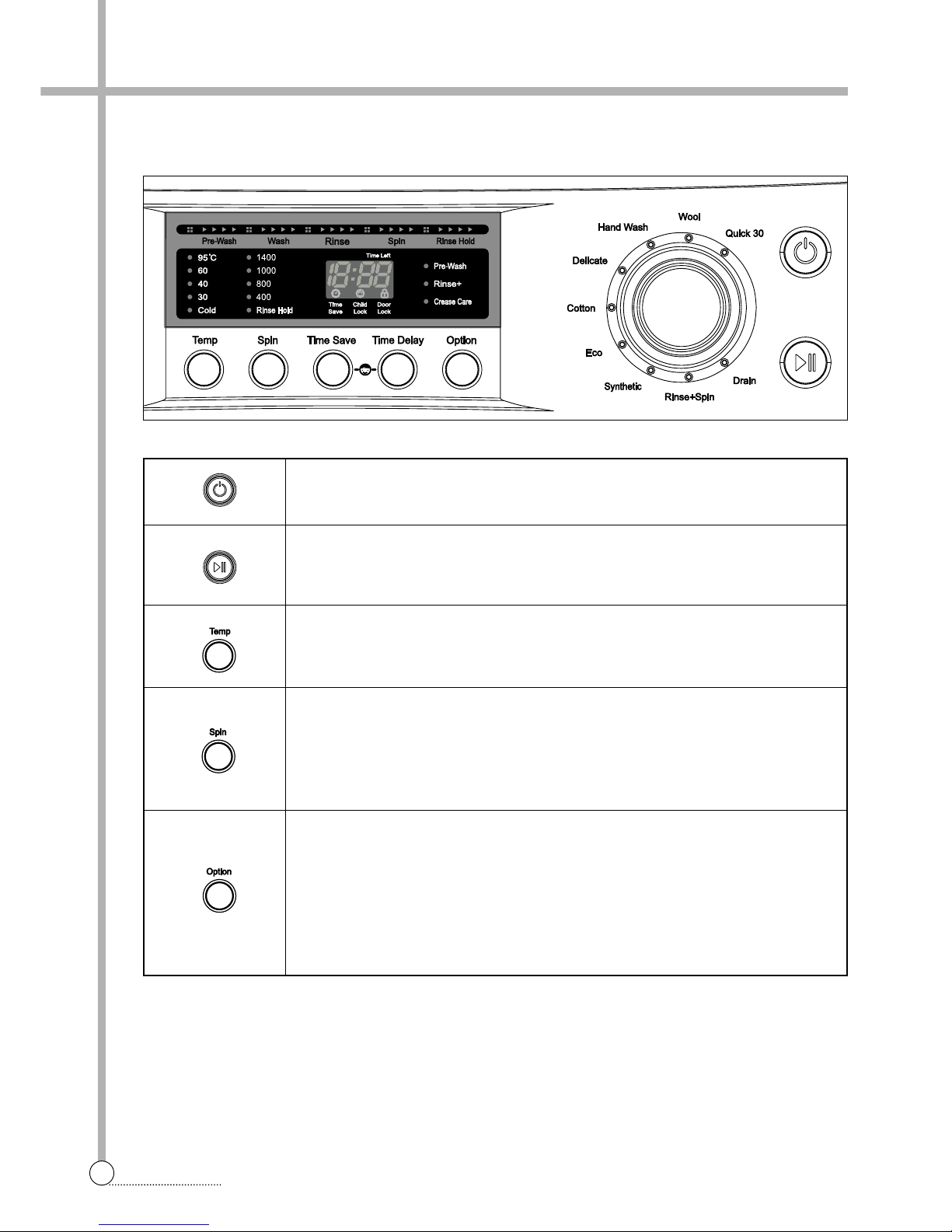
FUNCTIONS OF THE CONTROL PANEL
Power Button
Press this buton to turn the power ON or OFF.
Start/Hold Button
This button is use to start wash cycle or stop temporarily.
When you want to change program in operating, press this button.
T emperature Button
This button can be used to adjust temperature of water according to types of the
load to be washed.
Spin Speed Button
By pressing this button, the spin speed can be chosen.
Rinse Hold This function leaves clothes in the machine suspended in the water
after a rinse without entering into spin.
Spin only If you want only spin, you can operate spin only.
Option Button
By pressing this button, all option functions may be selected.
Pre-Wash If the laundry is heavily soiled, Pre-Wash course is effective.
Pre-Wash is available in Cotton and Synthetic.
Rinse+ By selecting Rise+ function, the rinse time and the rinse water are
increased.
Crease Care If you want to prevent crease, select this button with spin speed.
■ DWD-FD141X SERIES
6. FUNCTIONS OF THE CONTROL PANEL
Page 28
27
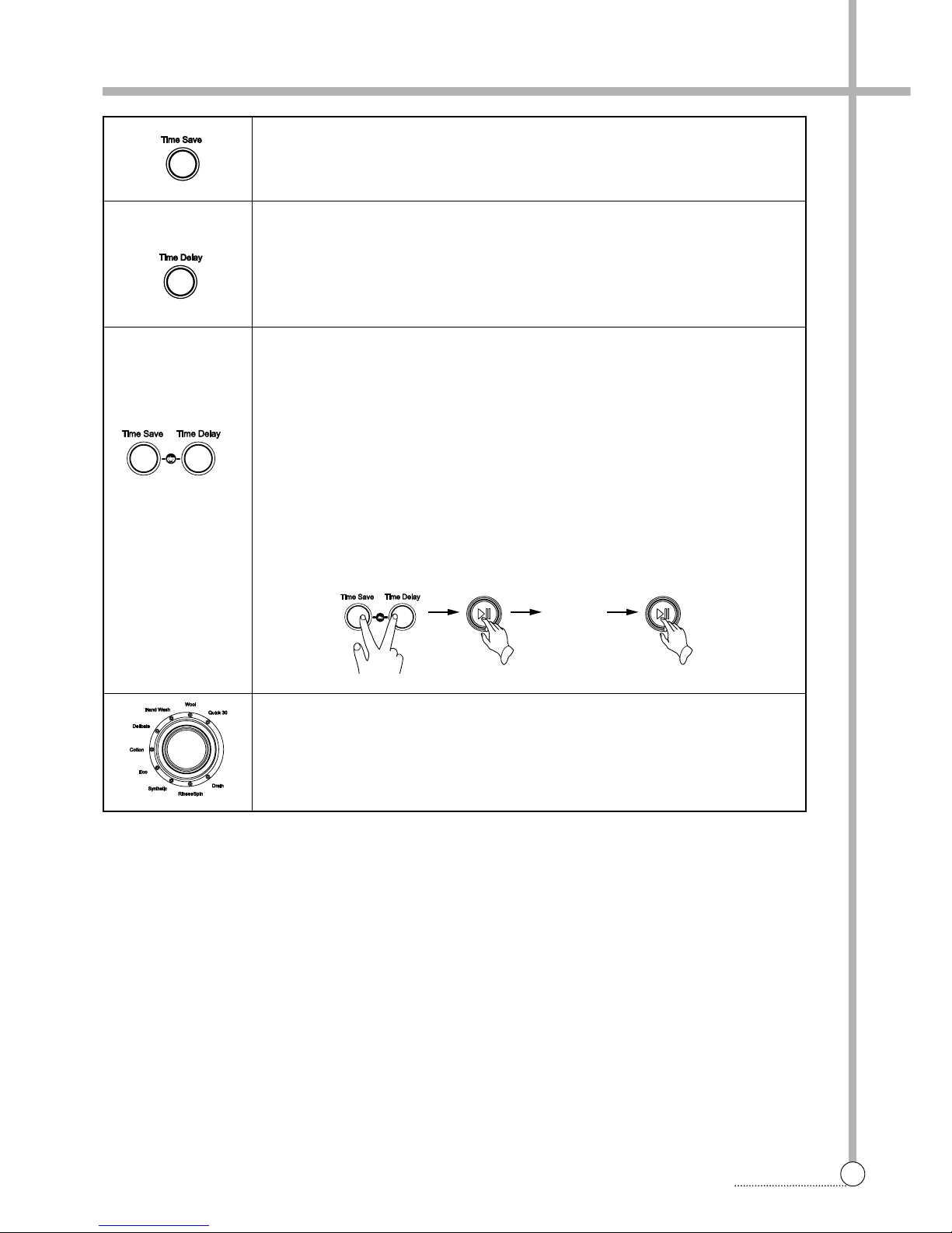
FUNCTIONS OF THE CONTROL PANEL
Child Lock Button
If you want to protect any accident occuring from handling of washer by a child, use
this function.
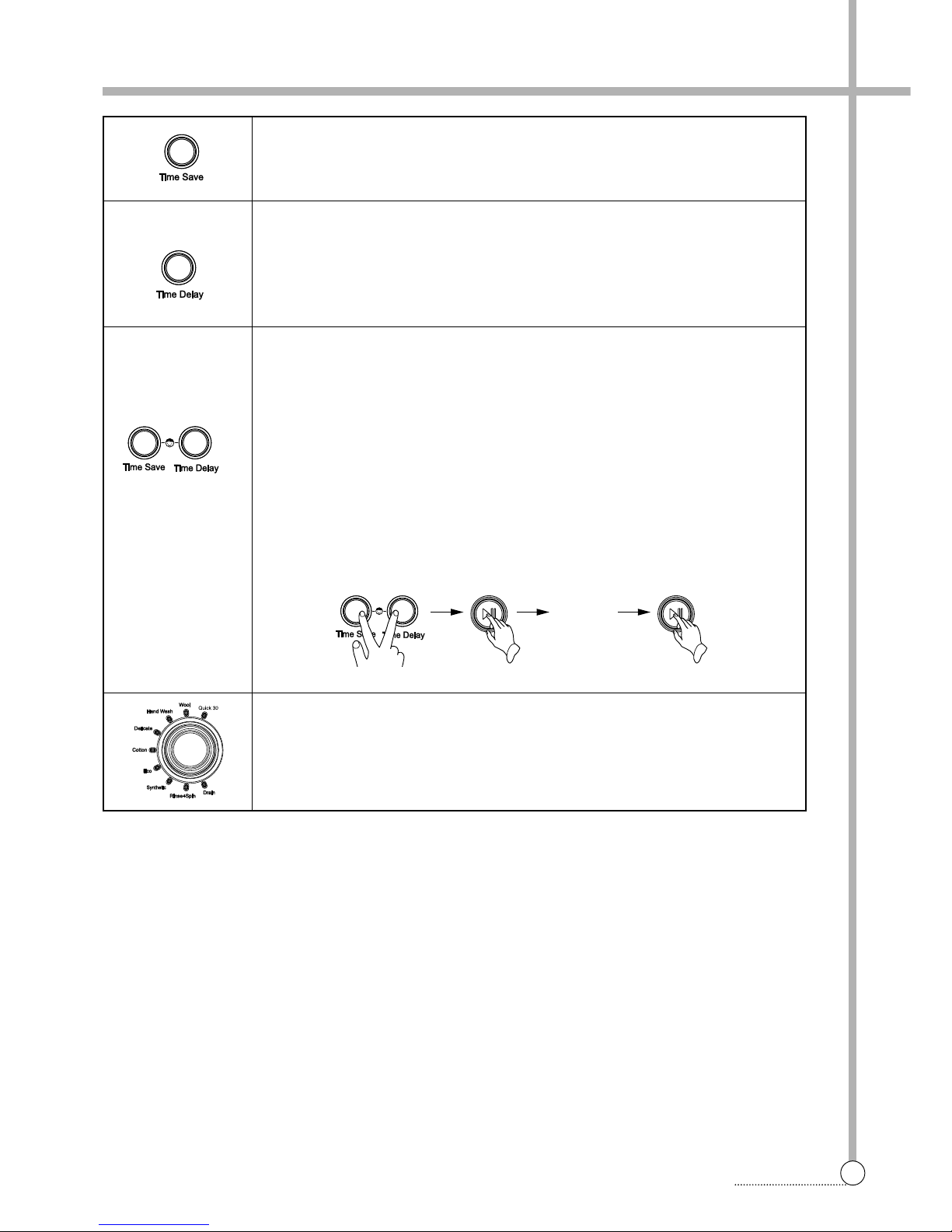
Child Lock can be set by pressing "Time Save" and "Time Delay" buttons simultaneously during 2~3seconds.
*When Child Lock is set, no button functions except Power button.
To cancel Chid Lock, press "Time Save" and "Time Delay" buttons simultaneously
again.
To change to the desired program, while in child lock mode.
1. Press both "Time Save" and "Time Delay" buttons together once again.
2. Press the Start/Hold button.
3. Select the desired program and press the Start/Hold button again.
Time Save Button
By pressing this button, you can decrease pre-set washing time to 10 minutes.
Time save is available in Cotton, Eco and Synthetic.
Time Delay Button
If you want to reserve the finishing time of washing, use this button.
If the Time Delay button is pressed, "2:00" is displayed. The maximum delayed time
is 12:00 hours and the minimum time is 2:00 hours.
Each pressing of the button advances on time delay by one hour.
Program Dial
When Start/Hold button is pressed, the Cotton program is automatically selected.
By turning the Program Dial, the program is selected in order of "Cotton↔Delicate
↔Hand Wash↔Wool↔Quick 30↔Drain↔Rinse+Spin↔Synthetic↔Eco"
Change
the desired
program
Page 29
28
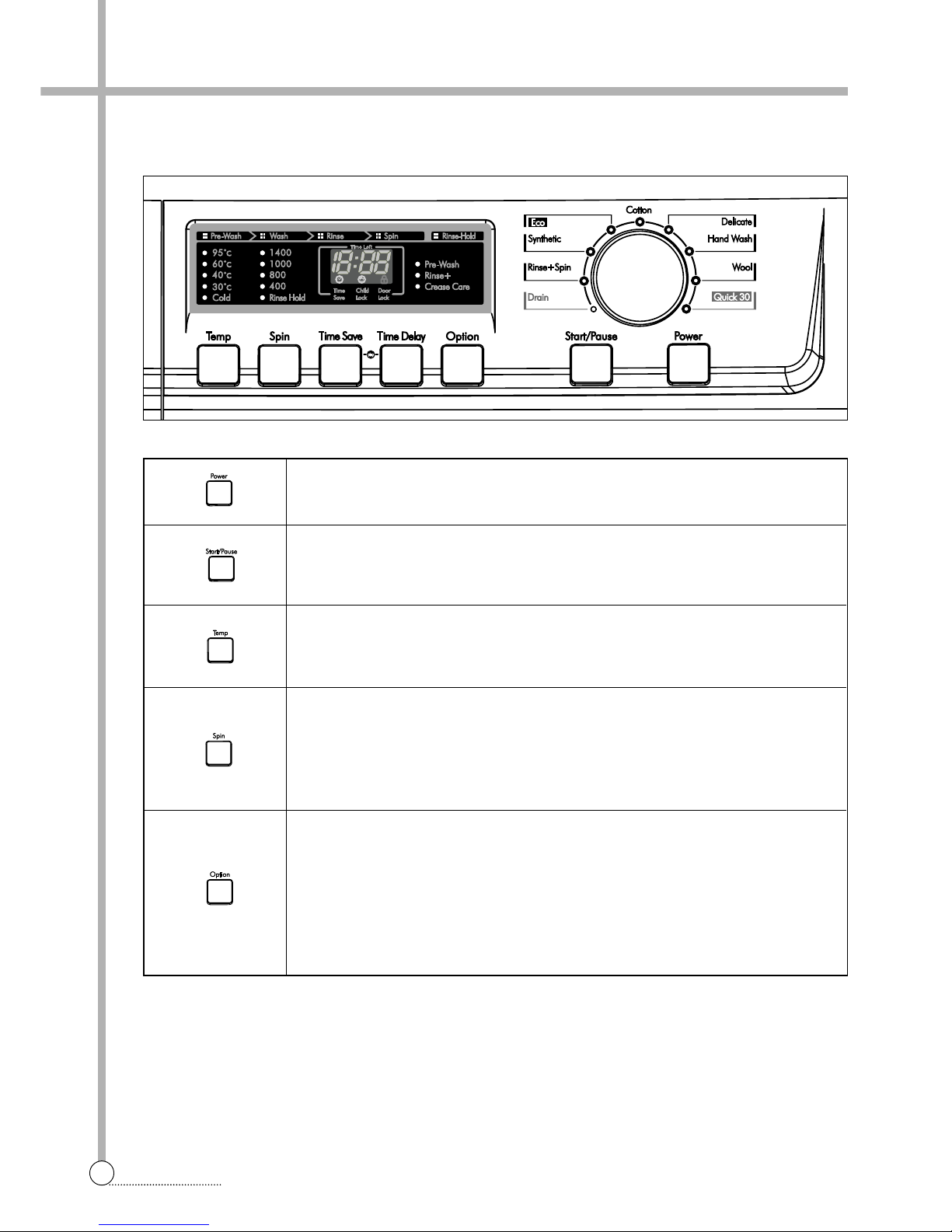
FUNCTIONS OF THE CONTROL PANEL
Power Button
Press this buton to turn the power ON or OFF.
Start/Hold Button
This button is use to start wash cycle or stop temporarily.
When you want to change program in operating, press this button.
T emperature Button
This button can be used to adjust temperature of water according to types of the
load to be washed.
Spin Speed Button
By pressing this button, the spin speed can be chosen.
Rinse Hold This function leaves clothes in the machine suspended in the water
after a rinse without entering into spin.
Spin only If you want only spin, you can operate spin only.
Option Button
By pressing this button, all option functions may be selected.
Pre-Wash If the laundry is heavily soiled, Pre-Wash course is effective.
Pre-Wash is available in Cotton and Synthetic.
Rinse+ By selecting Rise+ function, the rinse time and the rinse water are
increased.
Crease Care If you want to prevent crease, select this button with spin speed.
■ DWD-FD142X SERIES
Page 30
29
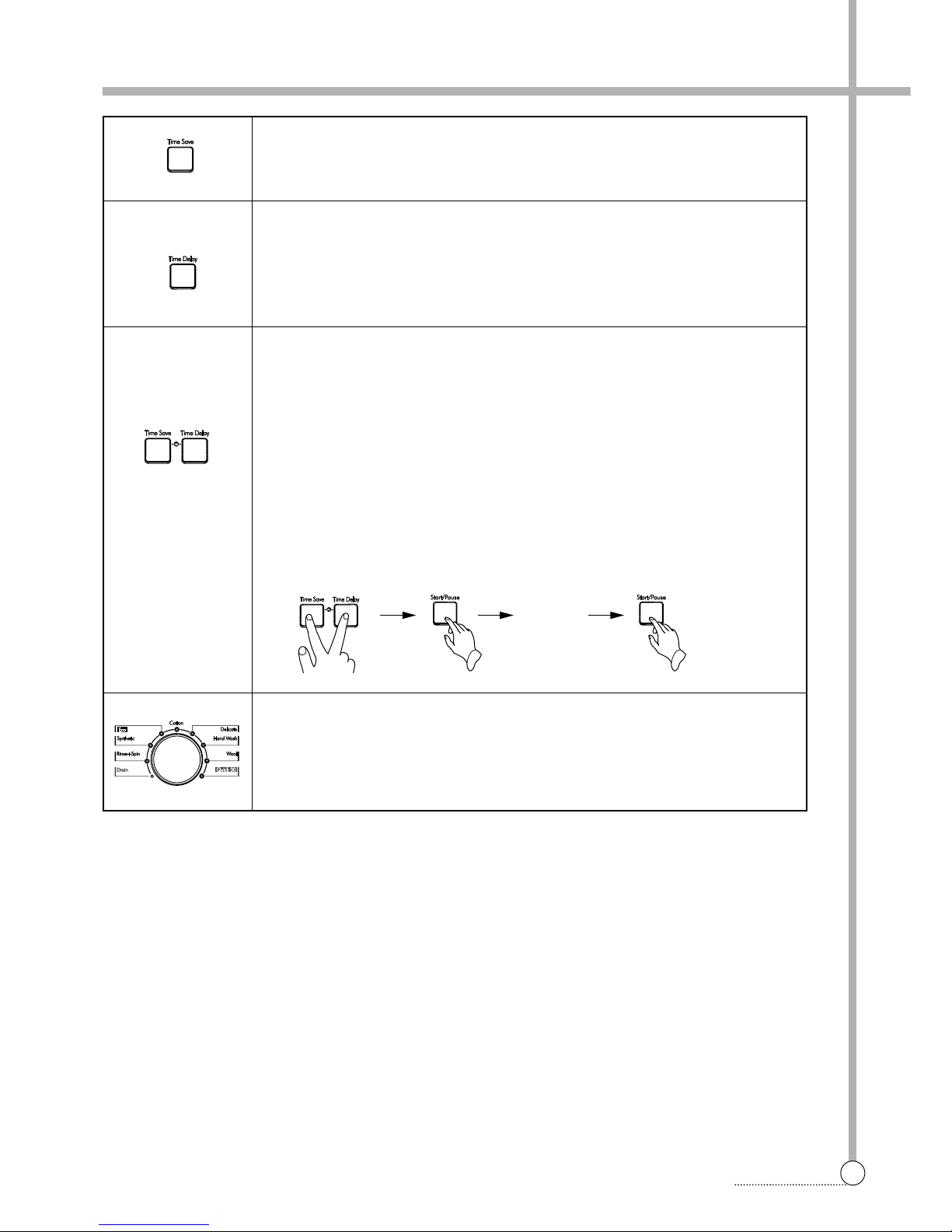
FUNCTIONS OF THE CONTROL PANEL
Child Lock Button
If you want to protect any accident occuring from handling of washer by a child, use
this function.
Child Lock can be set by pressing "Time Save" and "Time Delay" buttons simultaneously during 2~3seconds.
*When Child Lock is set, no button functions except Power button.
To cancel Chid Lock, press "Time Save" and "Time Delay" buttons simultaneously
again.
To change to the desired program, while in child lock mode.
1. Press both "Time Save" and "Time Delay" buttons together once again.
2. Press the Start/Hold button.
3. Select the desired program and press the Start/Hold button again.
Time Save Button
By pressing this button, you can decrease pre-set washing time to 10 minutes.
Time save is available in Cotton, Eco and Synthetic.
Time Delay Button
If you want to reserve the finishing time of washing, use this button.
If the Time Delay button is pressed, "2:00" is displayed. The maximum delayed time
is 12:00 hours and the minimum time is 2:00 hours.
Each pressing of the button advances on time delay by one hour.
Program Dial
When Start/Hold button is pressed, the Cotton program is automatically selected.
By turning the Program Dial, the program is selected in order of "Cotton↔Delicate
↔Hand Wash↔Wool↔Quick 30↔Drain↔Rinse+Spin↔Synthetic↔Eco"
Change
the desired
program
Page 31
30
FUNCTIONS OF THE CONTROL PANEL
Power Button
Press this buton to turn the power ON or OFF.
Start/Hold Button
This button is use to start wash cycle or stop temporarily.
When you want to change program in operating, press this button.
T emperature Button
This button can be used to adjust temperature of water according to types of the
load to be washed.
Spin Speed Button
By pressing this button, the spin speed can be chosen.
Rinse Hold This function leaves clothes in the machine suspended in the water
after a rinse without entering into spin.
Spin only If you want only spin, you can operate spin only.
Option Button
By pressing this button, all option functions may be selected.
Pre-Wash If the laundry is heavily soiled, Pre-Wash course is effective.
Pre-Wash is available in Cotton and Synthetic.
Rinse+ By selecting Rise+ function, the rinse time and the rinse water are
increased.
Crease Care If you want to prevent crease, select this button with spin speed.
■ DWD-FD143X SERIES
Page 32
31
FUNCTIONS OF THE CONTROL PANEL
Child Lock Button
If you want to protect any accident occuring from handling of washer by a child, use
this function.
Child Lock can be set by pressing "Time Save" and "Time Delay" buttons simultaneously during 2~3seconds.
*When Child Lock is set, no button functions except Power button.
To cancel Chid Lock, press "Time Save" and "Time Delay" buttons simultaneously
again.
To change to the desired program, while in child lock mode.
1. Press both "Time Save" and "Time Delay" buttons together once again.
2. Press the Start/Hold button.
3. Select the desired program and press the Start/Hold button again.
Time Save Button
By pressing this button, you can decrease pre-set washing time to 10 minutes.
Time save is available in Cotton, Eco and Synthetic.
Time Delay Button
If you want to reserve the finishing time of washing, use this button.
If the Time Delay button is pressed, "2:00" is displayed. The maximum delayed time
is 12:00 hours and the minimum time is 2:00 hours.
Each pressing of the button advances on time delay by one hour.
Program Dial
When Start/Hold button is pressed, the Cotton program is automatically selected.
By turning the Program Dial, the program is selected in order of "Cotton↔Delicate
↔Hand Wash↔Wool↔Quick 30↔Drain↔Rinse+Spin↔Synthetic↔Eco"
Change
the desired
program
Page 33
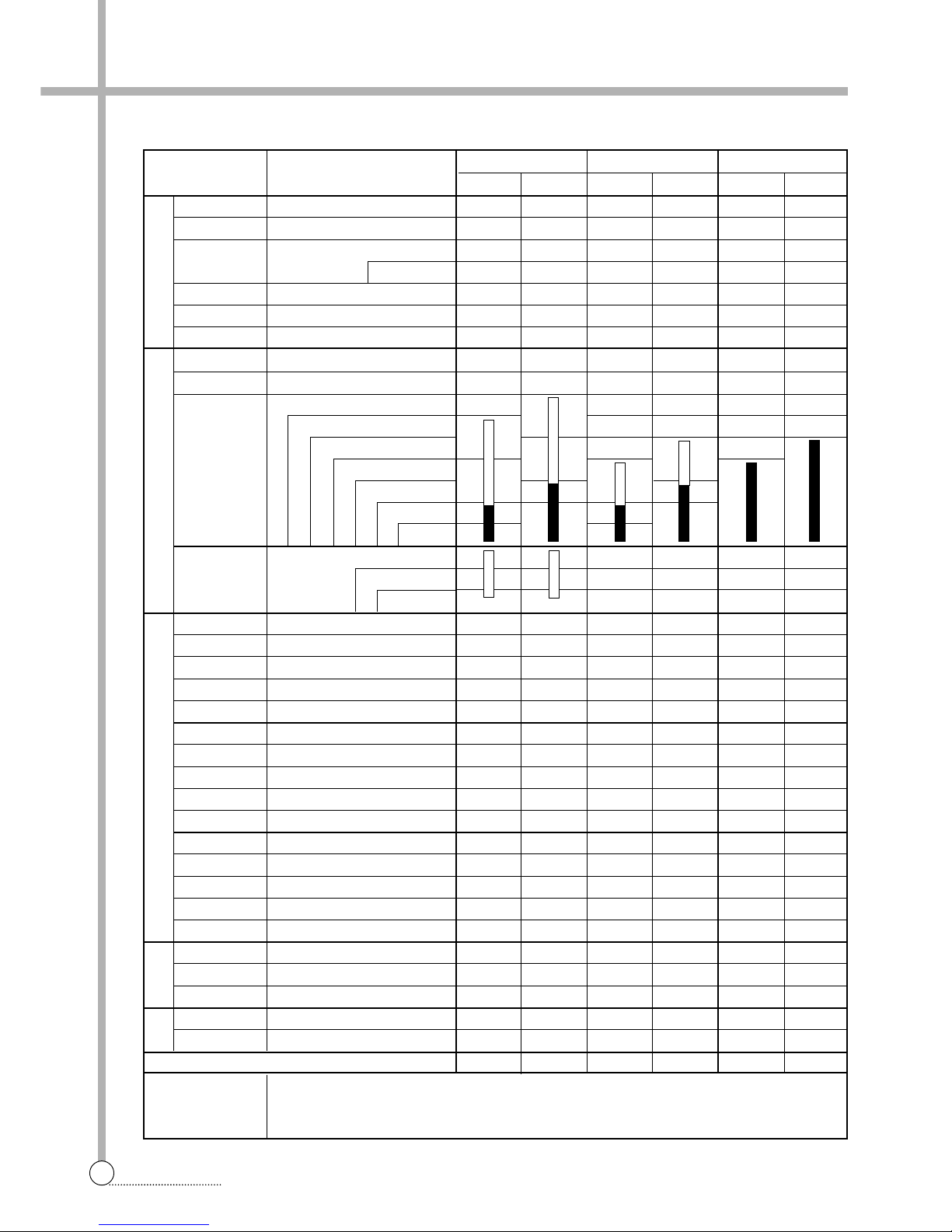
7. FUNCTIONS OF THE CONTROLLER
32
FUNCTIONS OF THE CONTROLLER
■ SEQUENCE CHART
Division Progress Time
SLSLSL
Sensing 20sec.
Water Supply 2min.
Pre Wash
10min.
8min.
Drain 1min.
B-Spin 1min.
Middle Spin 3min.
Sensing 20sec.
■■■■■■
Water Supply 2min.
■■■■■■
70min.
60min.
Wash 1 35min.
(Heating) 30min.
20min.
15min.
10min.
83min.
Wash 2 63min.
23min.
■■■■■■
Drain 1min.
■■■■■■
B-Spin 1min.
■■■■■■
Middle Spin 4min.
■■■■■■
Water Supply 2min.
■■■■■■
Rinse 1 3min.
■■■■■■
Drain 1min.
■■■■■■
B-Spin 1min.
■■■■■■
Middle Spin 4min.
■■■■■■
Water Supply 2min.
■■■■■■
Rinse 2 3min.
■■■■■■
Drain 1min.
■■■■■■
B-Spin 1min.
■■■■■■
Middle Spin 4min.
■■■■■■
Water Supply 2min.
■■■■■■
Rinse 3 3min.
■■■■■■
Drain 1min.
■■■■■■
B-Spin 1min.
■■■■■■
Main Spin 8min.
■■■■■■
Untangle 2min.
■■■■■■
End 10sec.
■■■■■■
Remained Time Display 1:25 1:30 1:25 1:30 1:40 1:45
NOTE
P
R
E
W
A
S
H
M
A
I
N
W
A
S
H
R
I
N
S
E
S
P
I
N
END
Cotton Synthetic Eco
• The washing time may vary by the amount of laundry, water pressure, water temperature and
other washing conditions. If an unbalanced load is detected of if suds removing program operates, the washing time maybe extended. (Maximum increasing time is about 1hour .)
Page 34
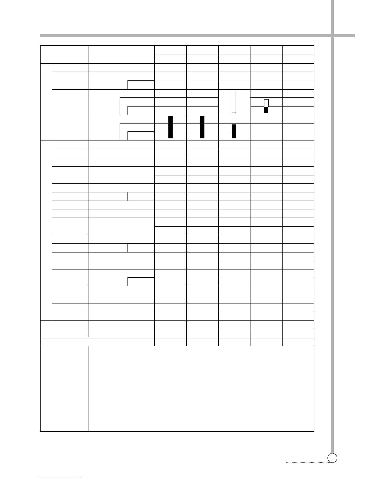
33
FUNCTIONS OF THE CONTROLLER
Wool Delicate Hand Wash Quick 30 Rinse+Spin
SSSSS
Soak 30min.
Water Supply
2min.
■■■
1min.
■
15min.
Wash 1
10min.
(Heating)
5min.
20min.
Wash 2 10min.
5min.
■
Drain 1min.
■■■■■
B-Spin 1min.
■■■ ■
Middle Spin 4min.
■■■ ■
Water Supply
2min.
■■■ ■
1min.
■
Rinse 1 3min.
■■■■■
Drain 1min.
■■■■
B-Spin 1min.
■■■
Middle Spin 4min.
■■■
Water Supply 2min.
■■■
1min.
■
Rinse 2 3min.
■■■■
Drain 1min.
■
B-Spin 1min.
■
Middle Spin 4min.
■
Water Supply
2min.
■
1min.
Rinse 3 3min.
■
Drain 1min.
■■■■■
B-Spin 1min.
■■■■■
Main Spin 8min.
■■■■■
Untangle 2min.
■■■■■
End 10sec.
■■■■■
Remained Time Display 56 56 57 33 23
NOTE
P
R
E
W
A
S
H
R
I
N
S
E
S
P
I
N
END
Division Progress Time
• The washing time may vary by the amount of laundry, water pressure, water temperature and
other washing conditions. If an unbalanced load is detected of if suds removing program operates, the washing time maybe extended. (Maximum increasing time is about 1hour .)
Page 35
8. FUNCTION OF THE CONVENIENT SERVICE
34
FUNCTION OF THE CONVENIENT SERVICE
■ The test mode of the operation
Y ou can check the PCB AS and the operation of the washing machine simply.
• The method to test and operate
1 Press the Power button.
2 Press the Option button 3 times while press the Temp button.
At this time, the version is displayed on the Custom LED
3 Whenever the Time Delay button is pressed, the washing machine is operated as following.
L_C (Lock Switch Close) →run/OO (The number of running times)
→E5/OO → E6/OO → E7/OO → E8/OO (The number of the error occurrence)
→H (Hot Valve) →C (Cold Valve) →P (Pre-Wash Valve)
→bb (Bubble) → dr (Drain Pump)
→C:H or C:-- (Cold & Hot Option)
→nPC or PC or etc. (PCB Option)→L_O (Lock Switch Open)
→L_C →
...
(repetition)
■ The check mode of the water level frequency
Y ou can check the water level frequency of the current state and the frequency by the variation of the water level.
• The method to test and operate
1 Press the Power button.
2 Press the Time Delay button 3 times while press the T emp button and the Spin button.
3 The water level frequency of the current state displays on “18:88 LED”.
At the same time, the cold valve is opened.
ex) 5 6 2 = 25.62kHz
: It display three number except the first number of 25.62kHz
4 Whenever the Temp button is pressed, the washing machine is operated as following.
Cold V alve Off (Initial state) → Cold Valve On
→Cold Valve Off → Drain Motor On
→Drain Motor Off
→Initial state → Cold V alve On →
...
(repetition)
Page 36
35
FUNCTION OF THE CONVENIENT SERVICE
■ The spinning test mode
Y ou can continually spin the washing machine with constant speed.
• The method to test and operate
1 Press the Power button.
2 Press the Time Save button 3 times while press T emp button.
3 “300” displays on “18:88 LED”. 300 means the spinning rpm.
Y ou can adjust the spinning rpm by pressing Spin button.
And this value increases by 50 up to 1400.
(300 →350 → 400 →
...
→1350 → 1400 → 300 → 350 →
...
)
4 When press Start button, the washing machine continually operates with given spinning rpm.
■ The durability test mode
Y ou can repetitively operate the washing machine with one course.
• The method to test and operate
1 Press the Power button.
2 Press the Time Delay button 3 times while press T emp button.
3 “d3” displays on “18:88 LED”. You can select the course by using Program Dial,
Temp button, Spin button, Option and Time Save button.
4 When press Start button, the washing machine repetitively operates with selected course.
Page 37
9. TROUBLESHOOTING GUIDE
36
FUNCTION OF THE CONVENIENT SERVICE
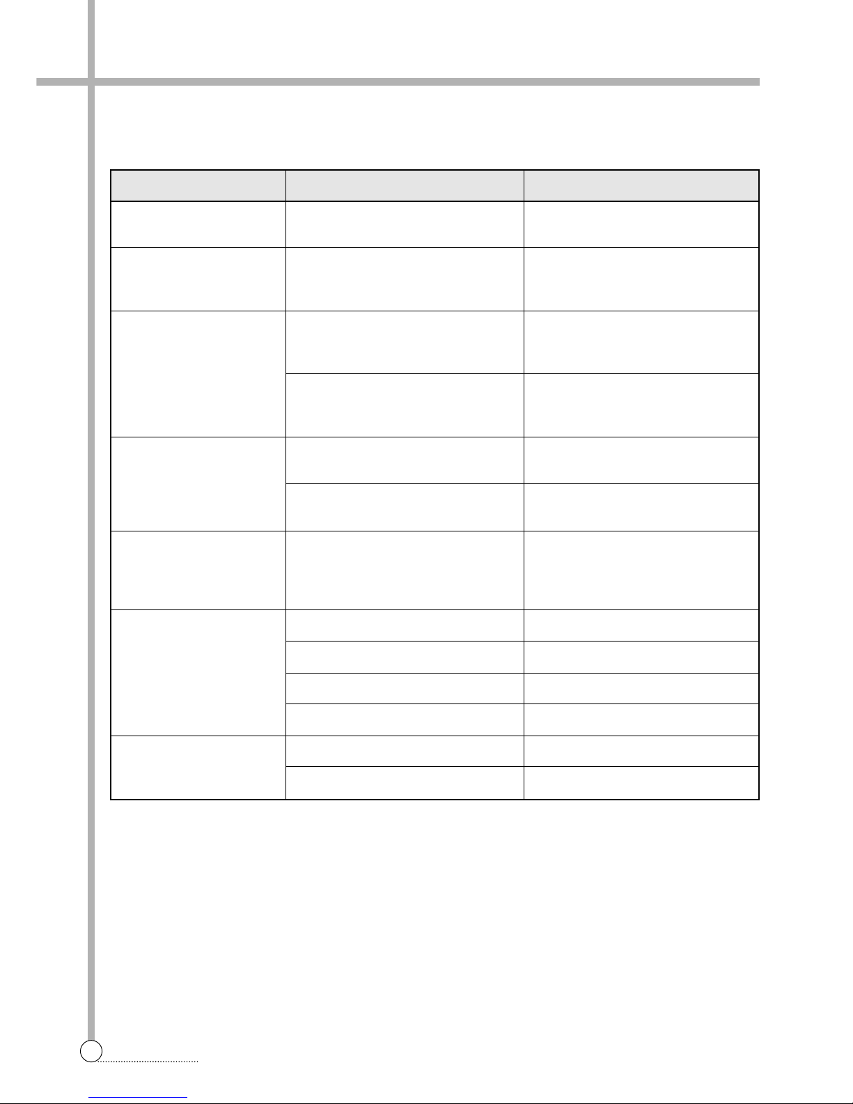
This wahing machine is equipped with automatic safety function which detect and diagnose faults at an early
stage and react appropriately.
When the machine does not function properly or does not fuction at all, check the following points.
SYMPTOM
Rattling and
clanking noise
Thumping sound
Vibrating noise
Water leaks.
Oversudsing
Water does not enter
washer or it enters slowly.
Water in the washer does
not drain or drains slowly.
CAUSE
Foreign objects such as coins or safety
pins maybe in the drum or pump
Heavy wash loads may produce a
thumping sound.
This is usually normal.
Have all the transit bolts and packing
been removed?
Are all the feet resting firmly on the
ground?
Inlet hoses or drain hose are loose at
tap or washer.
House drain pipes are clogged.
Water supply is not adequate in area.
Water supply tap is not completelyopen.
Water inlet hose is kinked.
The filer of the water inlet is clogged.
Drain hose is kinked or clogged.
The drain filter is clogged.
SOLUTION
Stop washer and check drum and filter.
If sound continues, washer is probably
out of balance. Stop and redistribute
wash load.
If not removees during installation.
Refer to Installation guide for removing
transit bolts.
Wash load may be unevely distributed
in drum. Stop washer and rearrange
wash load.
Check and tighten hose connections.
Unclog drain pipe. Contact plumber
if necessary .
Too much detergent or unsuitable
detergent may cause excessive
foaming which may result in water
leaks.
Check another tap in the inlet house.
Fully open tap.
Straighten hose.
Check the filter of the water inlet.
Clean and straighten drain hose.
Clean the drain filter.
Page 38
37
FUNCTION OF THE CONVENIENT SERVICE
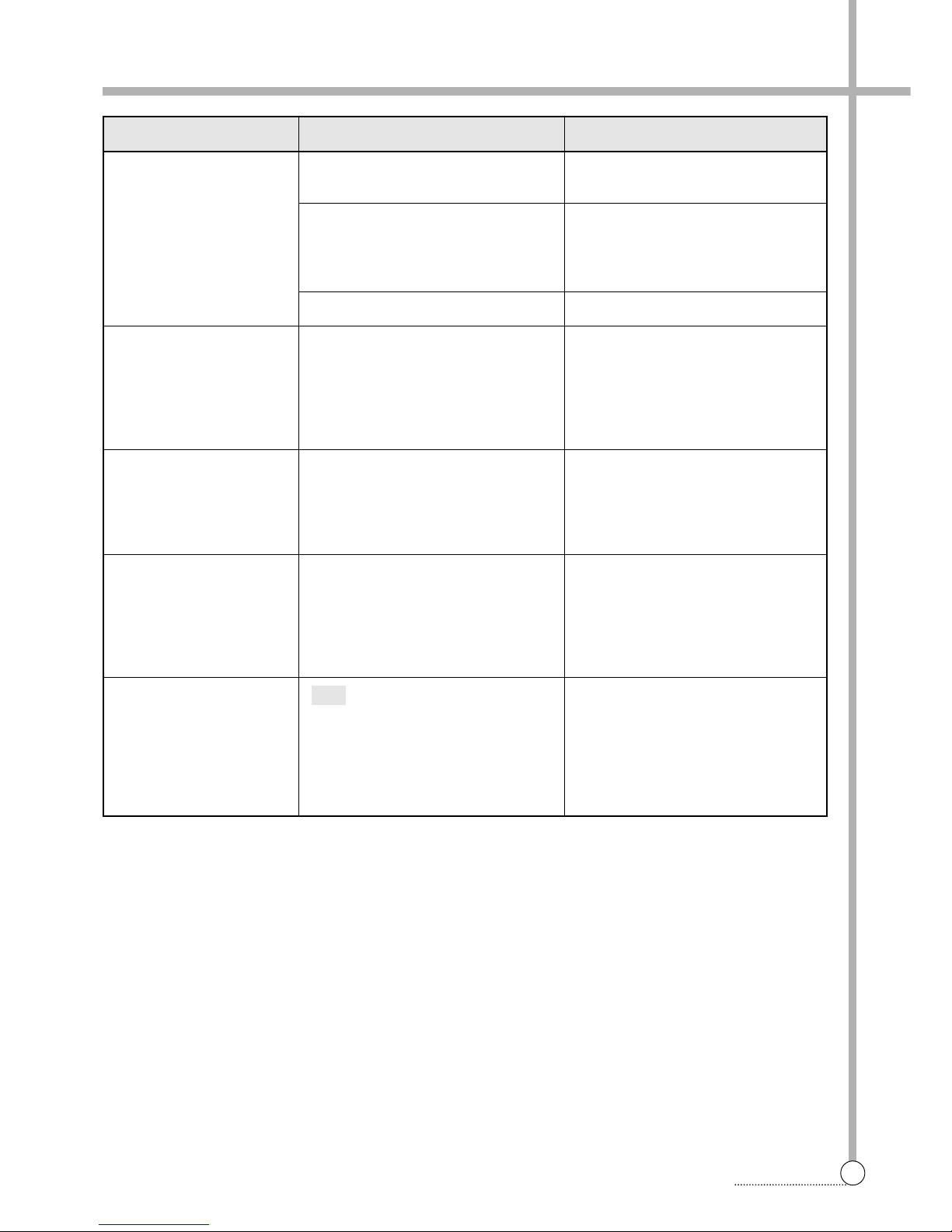
SYMPTOM
Washer does not start.
Washer will not spin.
Door does not open.
Wash cycle time delayed
The washer will stop during
spinning .
Spinning is insufficient.
CAUSE
Electronical power cord may not be
plugged in or connection may be loose.
House fuse blown, circuit breker
tripped, or a power outage has
occurred.
Water supply tap is not turned on.
Check that the door is firmly shut.
error due to much detergent and
unsuitable detergent
PFE
SOLUTION
Make sure plug fits tightly in wall outlet.
Reset circuit breaker or replace fuse.
Do not increase fuse capacity.
If problem is a circuit overload, have it
corrected by a qualified electrician.
Turn on water supply tap.
Close the door and press the
Start/Pause button. After pressing the
Start/Pause button, it may take a few
moments before the clothes washer
begines to spin. The door must lock
before spin can be achieved. "
Once started, the door can not be
opened for safety reasons.
Wait two minutes before opening the
door to give the electric locking
mechanism time to release.
The washing time may vary by the
amount of launtry, water pressure,
water temperature and other usage
conditions.
If the imbalance is detected, the wash
time shall be increased.
If PFE error mode was displayed on
the control part, in order to solve this
problem, first turn off the power of the
washing machine, second turn on the
power pressing Power button, third
press SPIN button and last press
Start/Hold button.
Page 39
38
TROUBLESHOOTING GUIDE
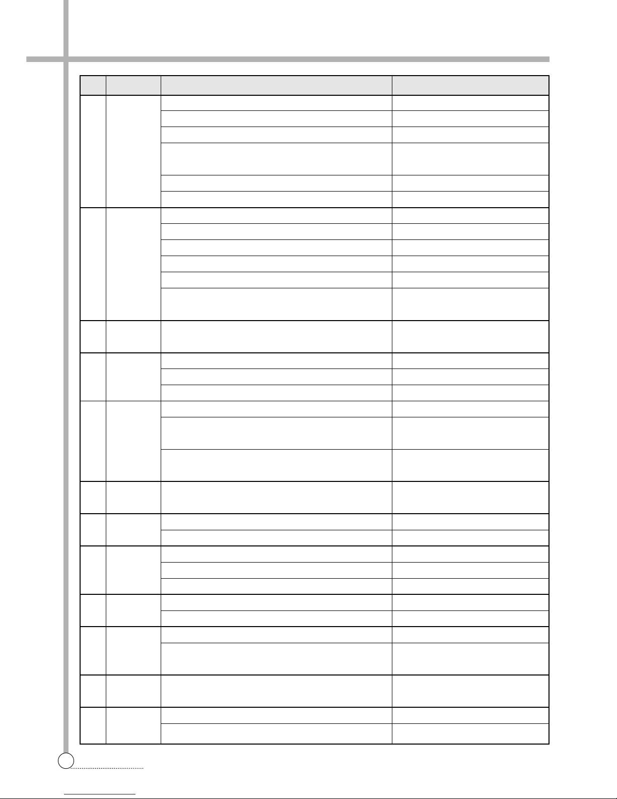
MESSAGE
ERROR CAUSE SOLUTION
The water tap is closed. Open the water tap.
The filter of the valve inlet is clogged. Clean the filter of the valve inlet.
The valve inlet is an inferior product or broke down. Change the valve inlet.
The water level sensor (sensor pressure) is an inferior product Change the water level sensor
or broke down. (sensor pressure).
The drain motor works during water supply. Change the drain motor.
The PCB ASS’Y does not check the water level. Change the PCB ASS’Y.
The drain hose is kinked or clogged. Clean and straighten the drain hose.
The drain motor is an inferior product. Change the drain motor.
The valve inlet works during drain. Change the valve inlet
The water level sensor is an inferior product. Change the water level sensor.
The PCB ASS’Y does not check the water level. Change the PCB ASS’Y.
The RPM of drum did not reach the setting RPM Clean the drain pump filter.
within the setting time during the spin. Or restart spin only course.
The laundry is concentrated to one side of the drum during spin. Rearrange the laundry.
The Start/Hold button is pressed while the door is opened. Close the door .
The switch door lock is an inferior product. Change the switch door lock.
The PCB ASS’Y does not check the door lock. Change the PCB ASS’Y.
The water is supplied continuously due to an inferior valve inlet. Change the valve inlet.
The valve inlet is normal, but the water level sensor Change the water level sensor
(sensor pressure) is inferior. (sensor pressure).
The drain motor dose not work.
Change the drain motor.
(The drain motor is an inferior product or broke down.)
Water leaks from the tub or the hose drain. Check the leak of the tub or the hose drain.
Then change the tub or the hose drain.
The laundry is jammed between the gasket and the drum. Rearrange the laundry.
The PCB ASS’Y is an inferior product. Change the PCB ASS’Y.
The laundry is jammed between the gasket and the drum. Rearrange the laundry.
The motor is an inferior product. Change the motor.
The PCB ASS’Y is an inferior product. Change the PCB ASS’Y.
The motor spins into an opposite direction. Change the PCB ASS or the motor.
The motor hall IC is an inferior product or broke down. Change the motor hall IC or the motor.
The motor is not normally connected. Check the connector of the motor.
The motor does not work.
Change the motor.
(The motor is an inferior product or broke down.)
The water level sensor is an inferior product. Change the water level sensor.
The thermistor wash is an inferior product or broke down. Change the thermistor wash.
The thermistor wash is not connected normally. Check the connector of the thermistor wash.
WA TER INLET
ERROR
DRAIN
ERROR
UNBALANCE
ERROR
DOOR OPEN
ERROR
OVERFLOW
ERROR
LEAKAGE
ERROR
HIGH VOL T AGE
ERROR
EMG ERROR
MOTOR
ERROR
SENSOR PRES-
SURE ERROR
THERMISTOR
WASH ERROR
IE
OE
UE
LE
E2
E4
E5
E6
E8
E9
H2
DIRECTION
ERROR
E7
Page 40
39
TROUBLESHOOTING GUIDE
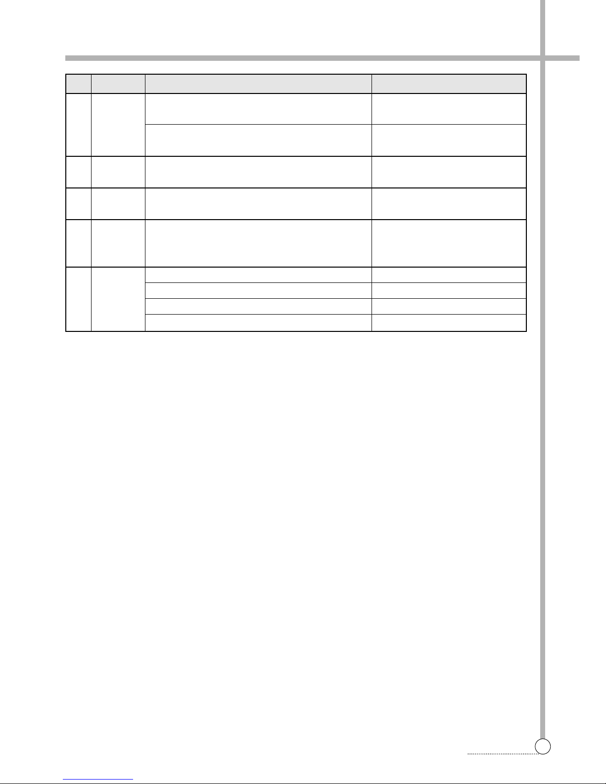
THERMISTOR
WASH
OVERHEA TING
ERROR
H4
MESSAGE
ERROR CAUSE SOLUTION
The heater worked without the water in the tub. Check the water level.
The thermistor wash is an inferior product or broke down. Change the thermistor wash.
The water temp. is over 45°C in delicate & wool course.
(The thermistor wash is an inferior product or broke down.)
Change the thermistor wash.
The heater wash dose not work.
(The water temp. doesn't rise over 2°C during 15min.)
Change the heater wash.
The heater worked without the water in the tub. Check the water level and the heater wash.
The drain pump filter is clogged. Clean the drain pump filter.
The drain pump does not work during spin. Change the drain pump.
The large amount of detergent was used. Use the proper amount of detergent.
The drain hose is placed higher than 1m above the floor. Place the drain hose 1m below the floor
WA TER TEMP.
ERROR
HEA TER WASH
ERROR
PUMP FIL TER
ERROR
HEA TER
WASH
OVERHEA TING
ERROR
H5
H6
H8
PFE
Page 41
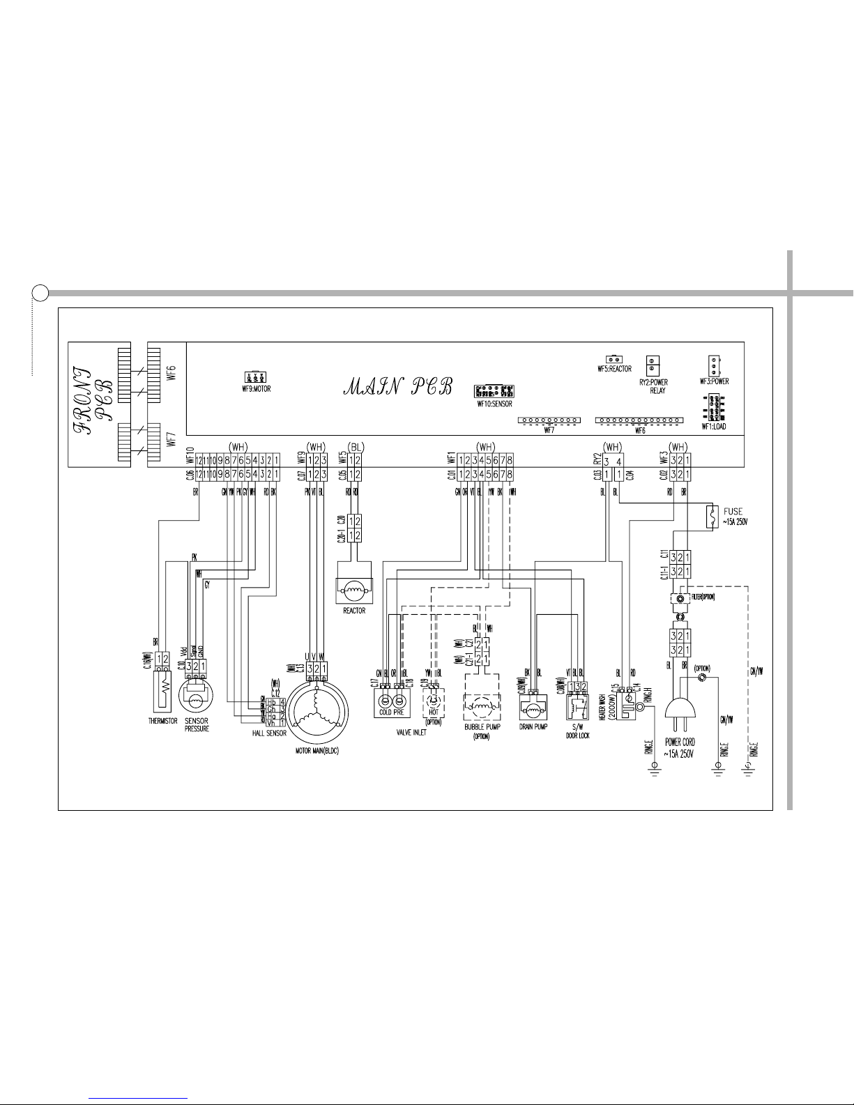
10. WIRING DIAGRAM
40
WIRING DIAGRAM
Page 42

S/M No. :
DAEWOO ELECTRONICS CORP.
686, AHYEON-DONG MAPO-GU SEOUL, KOREA
C.P.O. BOX 8003 SEOUL, KOREA
TELEX: DWELEC K28177-8
CABLE: “DAEWOOELEC”
PRINTED DATE: Mar. 2005
 Loading...