

Daewoo DWD-FD1413, DWD-FD1423, DWD-FD1432, DWD-FD1421, DWD-FD1433 Service Manual
...
Service Manual
Washing Machine
Model: DWD-FD1411/1412/1413
DWD-FD1421/1422/1423
DWD-FD1431/1432/1433
DWD-FD1441/1442/1443
DWD-FD1451/1452/1453
DWD-FD1461/1462/1463
DWD-FD1471/1472/1473
DAEWOO ELECTRONICS CORP.
S/M No. :
http : //svc.dwe.co.kr Sep. 2010
✔ Caution
: In this Manual, some parts can be changed for improving,
their performance without notice in the parts list. So, if you
need the latest parts information, please refer to PPL(Parts
Price List) in Service Information Center (http://svc.dwe.co.kr).

AUTO WASHER AUTO WASHER AUTO WASHER AUTO WASHER AUTO WASHER AUTO WASHER AUTO WASHER AUTO WASHER
AUTO WASHER AUTO WASHER AUTO WASHER AUTO WASHER AUTO WASHER AUTO WASHER AUTO WASHER AUTO WASHER
AUTO WASHER AUTO WASHER AUTO WASHER AUTO WASHER AUTO WASHER AUTO WASHER AUTO WASHER AUTO WASHER
AUTO WASHER AUTO WASHER AUTO WASHER AUTO WASHER AUTO WASHER AUTO WASHER AUTO WASHER AUTO WASHER
AUTO WASHER AUTO WASHER AUTO WASHER AUTO WASHER AUTO WASHER AUTO WASHER AUTO WASHER AUTO WASHER
AUTO WASHER AUTO WASHER AUTO WASHER AUTO WASHER AUTO WASHER AUTO WASHER AUTO WASHER AUTO WASHER
AUTO WASHER AUTO WASHER AUTO WASHER AUTO WASHER AUTO WASHER AUTO WASHER AUTO WASHER AUTO WASHER
AUTO WASHER AUTO WASHER AUTO WASHER AUTO WASHER AUTO WASHER AUTO WASHER AUTO WASHER AUTO WASHER
AUTO WASHER AUTO WASHER AUTO WASHER AUTO WASHER AUTO WASHER AUTO WASHER AUTO WASHER AUTO WASHER
AUTO WASHER AUTO WASHER AUTO WASHER AUTO WASHER AUTO WASHER AUTO WASHER AUTO WASHER AUTO WASHER
AUTO WASHER AUTO WASHER AUTO WASHER AUTO WASHER AUTO WASHER AUTO WASHER
WASHING MACHINE
Contents
1. SPECIFICATIONS....................................................................................................................2
2. INSTALLATION .......................................................................................................................8
Removing transit bolts...................................................................................................8
Installation place requirement.......................................................................................9
BS Plug Safety Details (For U.K. User).........................................................................9
Connecting inlet hose..................................................................................................10
Installation of drain hose.............................................................................................11
Level adjustment ..........................................................................................................12
3. MAINTENANCE................................................................................................................. .... 13
Cleaning your washer ..................................................................................................13
Cold condition...............................................................................................................13
Cleaning the water inlet filter ......................................................................................14
Cleaning the drain pump filter.....................................................................................14
Cleaning the detergent case........................................................................................15
Cleaning the washing drum.........................................................................................15
4. DIRECTION FOR DISASSEMBLY........................................................................................16
5. EXPLODE VIEW AND PARTS LIST.....................................................................................19
6. FUNCTIONS OF THE CONTROL PANEL............................................................................42
7. FUNCTIONS OF THE CONTROLLER..................................................................................56
8. FUNCTION OF THE CONVENIENT SERVICE.....................................................................58
9. TROUBLESHOOTING GUIDE..............................................................................................61
10. WIRING DIAGRAM..............................................................................................................65
2
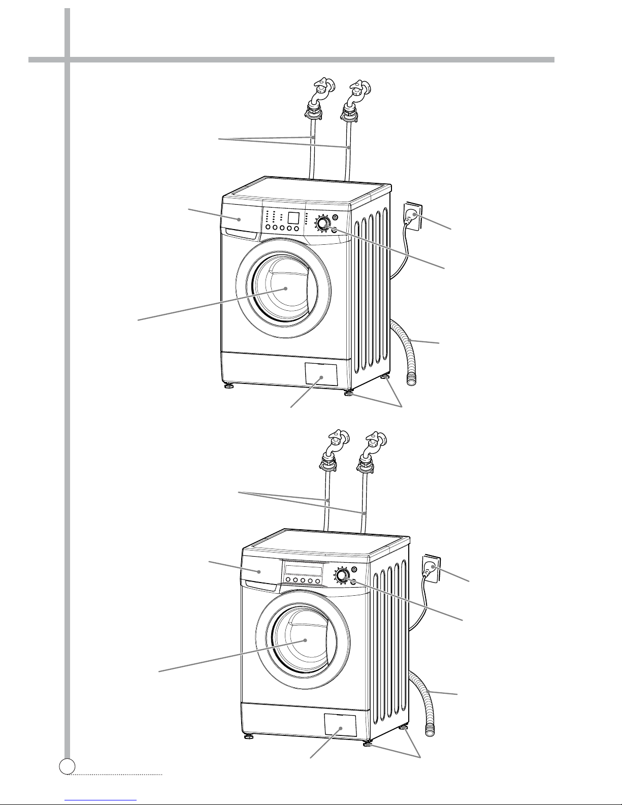
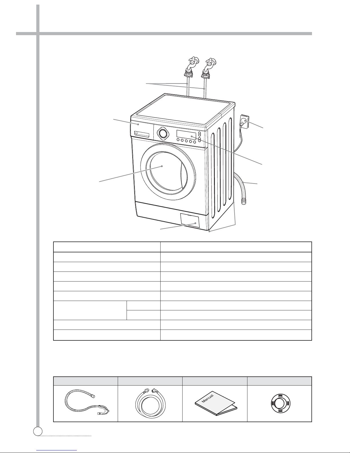
SPECIFICATIONS
ADJUSTABLE LEG
CONTROL PANEL
DOOR
DETERGENT CASE
INLET HOSE
HOT
(OPTION)
COLD
LOWER COVER
POWER CORD
HOSE DRAIN
■
DWD-FD141X SERIES
■
DWD-FD142X SERIES
HOT
(OPTION)
COLD
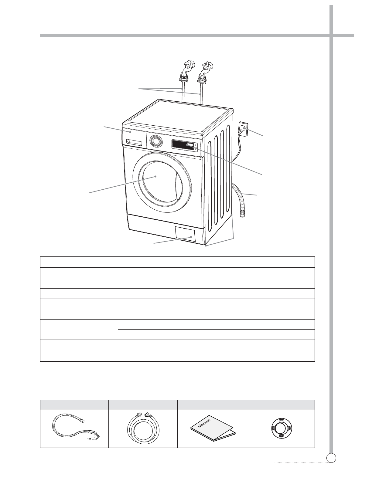
ADJUSTABLE LEG
CONTROL PANEL
DOOR
DETERGENT CASE
INLET HOSE
LOWER COVER
POWER CORD
HOSE DRAIN
3
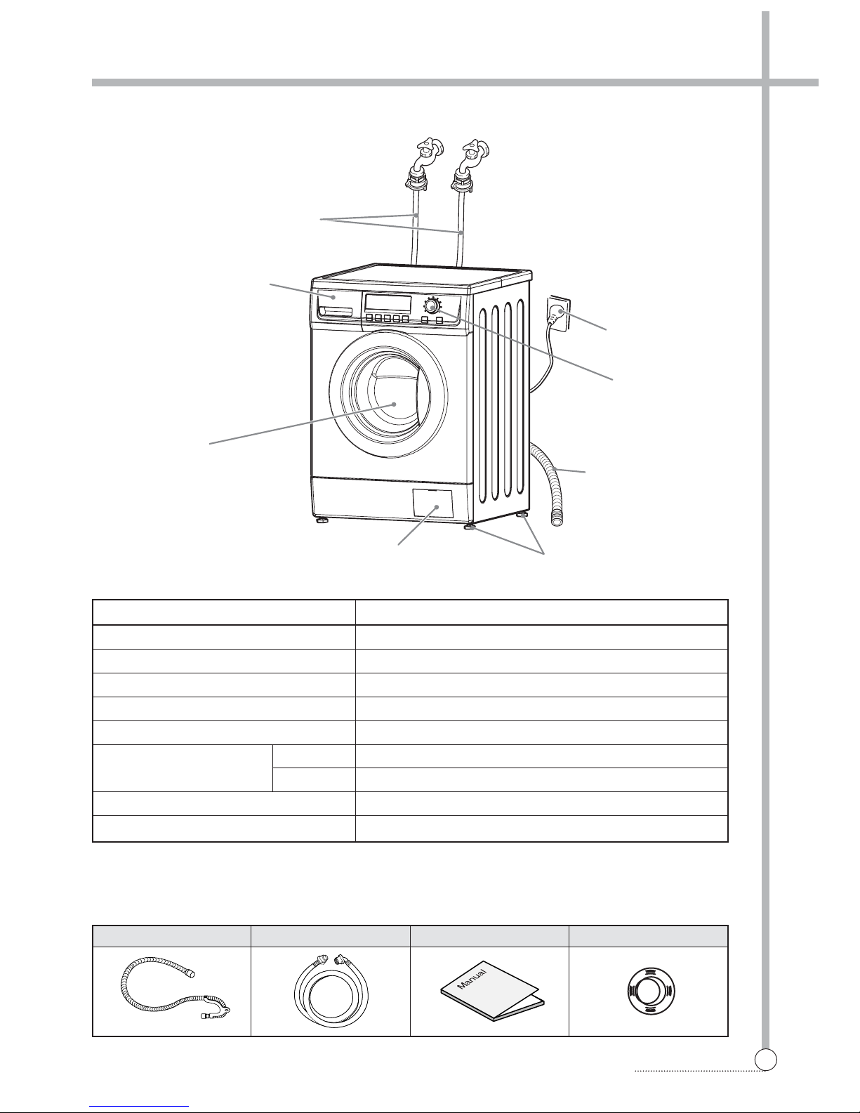
SPECIFICATIONS
HOT
(OPTION)
COLD
■
DWD-FD143X SERIES
ADJUSTABLE LEG
CONTROL PANEL
DOOR
DETERGENT CASE
INLET HOSE
LOWER COVER
POWER CORD
HOSE DRAIN
Hose drain Inlet hose Manual Cap holder(3EA)
■
Accessories
POWER SOURCE 220-240V, 50/60Hz
DiMENSION (WXDXH) 595mm x 540mm x 850mm
WEIGHT 58 kg
WATER CONSUMPTION 56.1
ℓ
POWER CONSUMPTION 2200W
MAXIMUM MASS WASH 7 kg
OF TEXTILE SPIN 7 kg
WASHER TYPE DRUM TYPE (FRONT LOADING WASHING MACHINE)
OPERATING WATER PRESSURE 0.3 ~ 8kgf/cm2(29.4 ~ 784kPa)
MODEL
DWD-FD1411/1412/1413, DWD-FD1421/1422/1423, DWD-FD1431/1432/1433
4
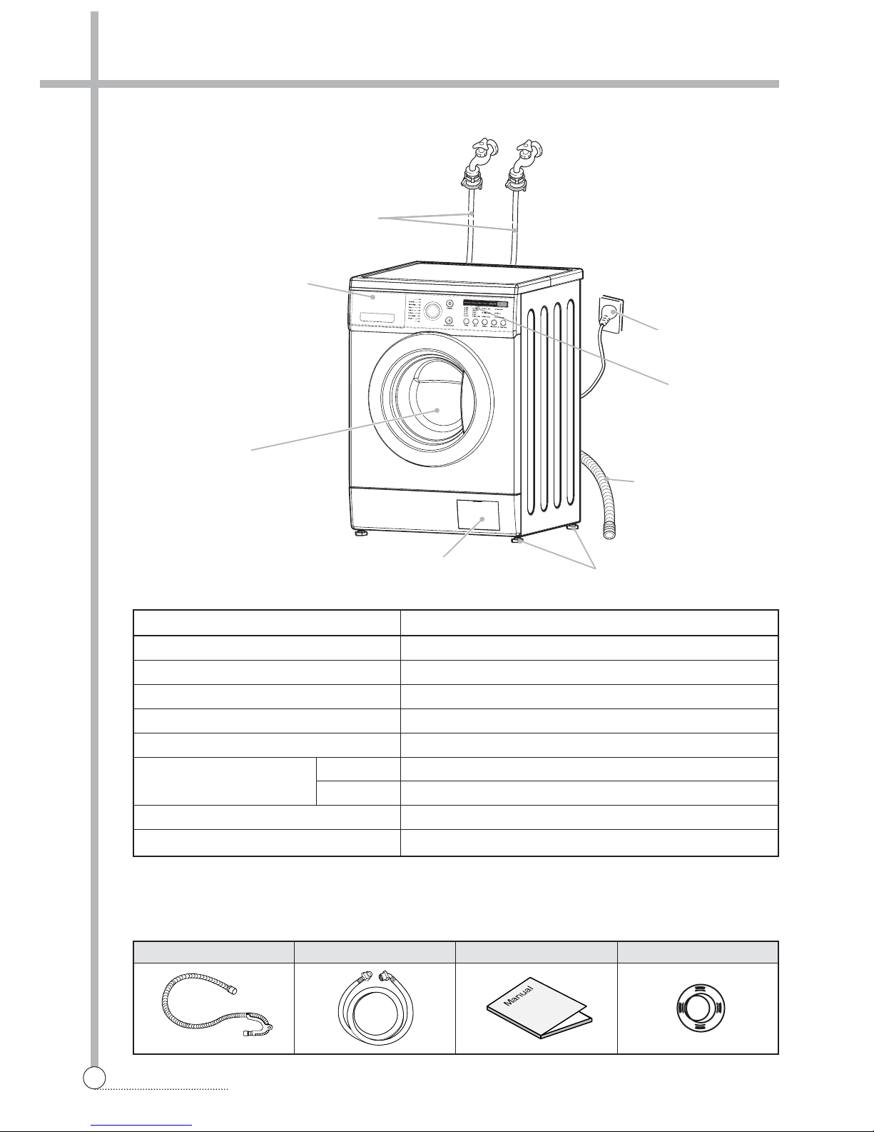
SPECIFICATIONS
HOT
(OPTION)
COLD
■
DWD-FD144X SERIES
ADJUSTABLE LEG
CONTROL PANEL
DOOR
DETERGENT CASE
INLET HOSE
LOWER COVER
POWER CORD
HOSE DRAIN
Hose drain Inlet hose Manual Cap holder(3EA)
■
Accessories
POWER SOURCE 127V/60Hz , 220-240V/50-60Hz
DiMENSION (WXDXH) 595mm x 540mm x 850mm
WEIGHT 58 kg
WATER CONSUMPTION 56.1
ℓ
POWER CONSUMPTION 2200W
MAXIMUM MASS WASH 7 kg
OF TEXTILE SPIN 7 kg
WASHER TYPE DRUM TYPE (FRONT LOADING WASHING MACHINE)
OPERATING WATER PRESSURE 0.3 ~ 8kgf/cm2(29.4 ~ 784kPa)
MODEL DWD-FD1441/1442/1443/1444/1445
5
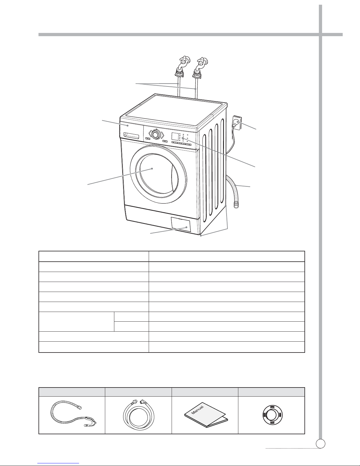
SPECIFICATIONS
Hose drain Inlet hose Manual Cap holder(3EA)
■
Accessories
■
DWD-FD145X SERIES
DETERGENT CASE
INLET HOSE
HOT
(OPTION)
COLD
DOOR
LOWER COVER
ADJUSTABLE LEG
HOSE DRAIN
CONTROL PANEL
POWER CORD
POWER SOURCE 220-240V/50-60Hz
DiMENSION (WXDXH) 595mm x 540mm x 850mm
WEIGHT 58 kg
WATER CONSUMPTION 56.1
ℓ
POWER CONSUMPTION 2200W
MAXIMUM MASS WASH 7 kg
OF TEXTILE SPIN 7 kg
WASHER TYPE DRUM TYPE (FRONT LOADING WASHING MACHINE)
OPERATING WATER PRESSURE 0.3 ~ 8kgf/cm2(29.4 ~ 784kPa)
MODEL DWD-FD1451/1452/1453/1454/1455
6
SPECIFICATIONS
Hose drain Inlet hose Manual Cap holder(3EA)
■
Accessories
DETERGENT CASE
INLET HOSE
■
DWD-FD146X SERIES
POWER SOURCE 220-240V, 50/60Hz
DiMENSION (WXDXH) 595mm x 540mm x 850mm
WEIGHT 58 kg
WATER CONSUMPTION 56.1
ℓ
POWER CONSUMPTION 2200W
MAXIMUM MASS WASH 7 kg
OF TEXTILE SPIN 7 kg
WASHER TYPE DRUM TYPE (FRONT LOADING WASHING MACHINE)
OPERATING WATER PRESSURE 0.3 ~ 8kgf/cm2(29.4 ~ 784kPa)
MODEL DWD-FD1461/1462/1463/1464/1465
HOT
(OPTION)
COLD
DOOR
LOWER COVER
ADJUSTABLE LEG
HOSE DRAIN
CONTROL PANEL
POWER CORD
7
SPECIFICATIONS
Hose drain Inlet hose Manual Cap holder(3EA)
■
Accessories
■
DWD-FD147X SERIES
POWER SOURCE 220-240V/50-60Hz
DiMENSION (WXDXH) 595mm x 540mm x 850mm
WEIGHT 58 kg
WATER CONSUMPTION 56.1
ℓ
POWER CONSUMPTION 2200W
MAXIMUM MASS WASH 8 kg
OF TEXTILE SPIN 8 kg
WASHER TYPE DRUM TYPE (FRONT LOADING WASHING MACHINE)
OPERATING WATER PRESSURE 0.3 ~ 8kgf/cm2(29.4 ~ 784kPa)
MODEL DWD-FD1471/1472/1473/1474/1475
DETERGENT CASE
INLET HOSE
HOT
(OPTION)
COLD
DOOR
LOWER COVER
ADJUSTABLE LEG
HOSE DRAIN
CONTROL PANEL
POWER CORD

2. INSTALLATION
8
INSTALLATION
■ Transit bolts
The appliance is fitted with transit bolts to prevent internal damage during transport.
■ Removing transit bolts
1. To prevent internal damage during transport, the
special 3 bolts are locked. Before operating the
washer, remove the bolts along with the rubber
bungs.
• If they are not removed, it may cause heavy
vibration, noise and malfunction.
2. Unscrew the 3 bolts with the 10mm hex wrench
or spanner or cross-tip screwdriver.
Keep the 3 bolts for a later time.
• When the appliance is transported, transit bolts
will be re-used.
3. Close the holes with the caps supplied.
■ Transit bolts
The appliance is fitted with transit bolts to prevent internal damage during transport.
■ Removing transit bolts
9
INSTALLATION
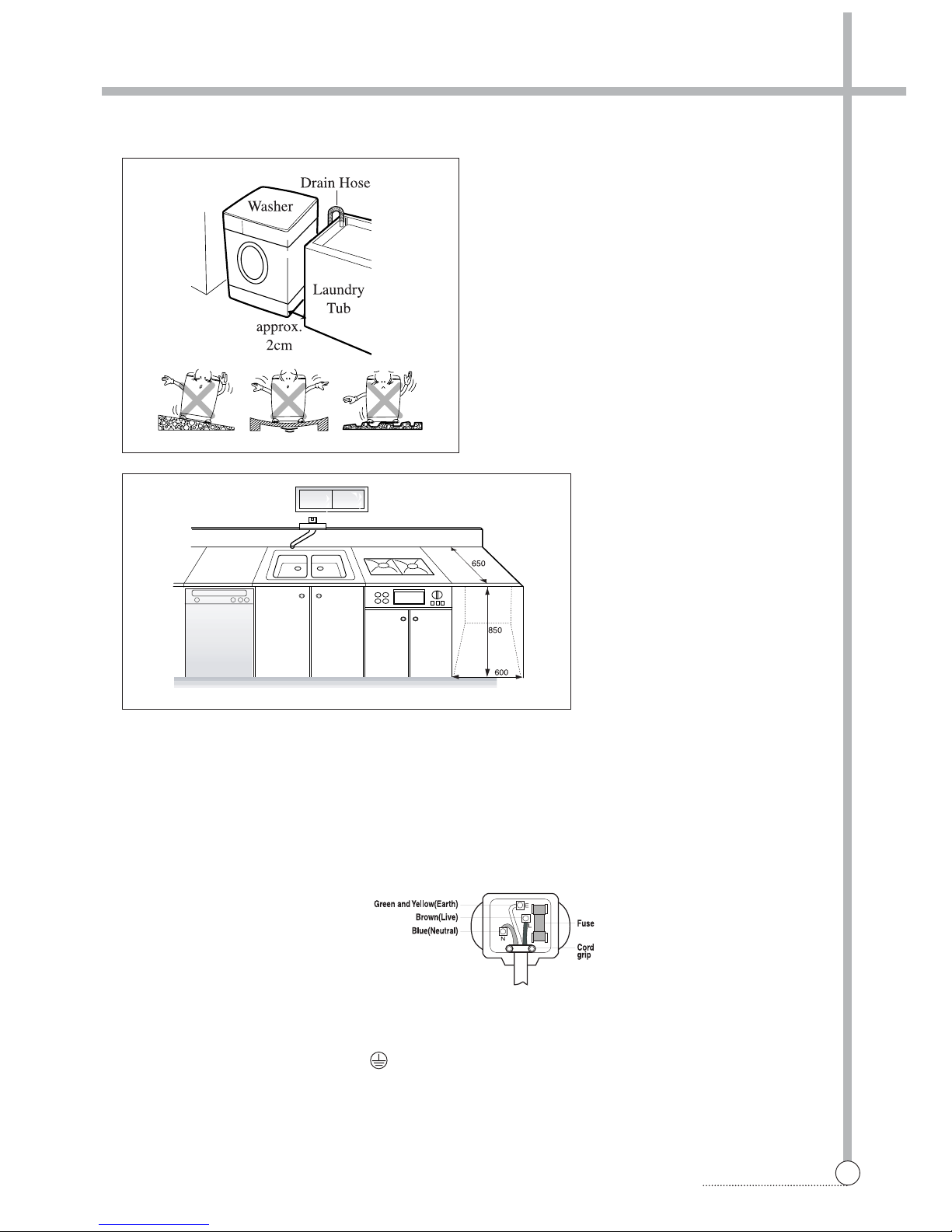
■ Installation place requirement
■ BS Plug Safety Details (For U.K. User)
Level floor :
Allowable slope under entire washer is 1°.
Power outlet :
Must be with 1.5 meters of entire side of location of
washer. Do not overload the outlet with more than
one appliance.
Additional Clearance :
For wall, door and floor modeling is required.
(10cm : rear / 2cm : right & left side)
Do not place or store laundry products on top of
washer at any times.
They can damage the finish or controls.
As the colours of the wires in the mains lead of this apparatus may not correspond with the coloured markings
identifying the terminals in your plug, proceed as follows:
The wire which is coloured Green and Yellow must be connected to the terminal in the plug which is marked
with the letter E or by the earth symbol or coloured Green or Green and Yellow.
The wire which is coloured Blue must be connected to the terminal which is marked with the letter N or coloured Black.
The wire which is coloured Brown must be connected to the terminal which is marked with the letter L or
coloured Red.
If a 13 amp (BS 1363) plug is used, fit a 13amp BS 1362 fuse.
IMPORTANT
THE WIRES IN THIS MAINS LEAD ARE COLOURED IN ACCORDANCE WITH THE FOLLOWING CODE:
GREEN AND YELLOW : EARTH
BLUE : NEUTRAL
BROWN : LIVE
This appliance must be earthed

10
INSTALLATION
FOR ORDINARY TAP
6 Connect the inlet hose
adapter of the hose to the
water inlet of the washer by
turning it clockwise to be fixed
tightly.
• Please check the rubber
packing present inside the inlet
hose adapter of the hose.
1 Pull down the collar
of the inlet hose to
separate it from the
water tap adapter.
2 Loosen the four
screws properly in
order to fit into
water tap.
4 Remove the tape,
and screw connector
B into connector A
tightly.
5 Connect the inlet
hose to the water tap
adapter by pulling
down the collar of the
hose end.
3 Fit the water tap adapter into
the water tap and tighten the
four screws evenly while
pushing up the adapter so that
the
rubber packing can stick to the
water tap tightly.
■ Connecting inlet hose
In using only one water tap or in case of only one water inlet valve, connect the inlet hose to the cold water inlet valve.
Option : Be careful not to confuse hot water inlet and cold water inlet.
FOR SCREW-SHAPED TAP
3
Connect the inlet hose adapter
to the water inlet of the washer
and turn it to be fixed.
• Check the packing in the inlet.
1 Connect the inlet hose
to the water tap
adapter by pulling
down the collar of the
hose end.
2
Connect the
connector- inlet
supplied if
necessary.
Inlet Hose
Connector D
Rubber
Packing
Connector C
Connector
Inlet
Rubber
Packing
Connector D
Connector C
Hose
TAPE
Connector B
Connector A

11
INSTALLATION
■ Installation of drain hose
• When installing the drain hose in sink, secure
it tightly with a string.
• Proper securing of the drain hose will protect the
floor from damage due to water leakage.
• The drain hose should not be placed higher than
100cm above the floor.
• Proper securing of the drain hose will protect the
floor from damage due to water leakage.
• When the drain hose is too long, do not force
back in to the washer. This will cause
abnormal noise.
■ Installation of drain hose
12
INSTALLATION
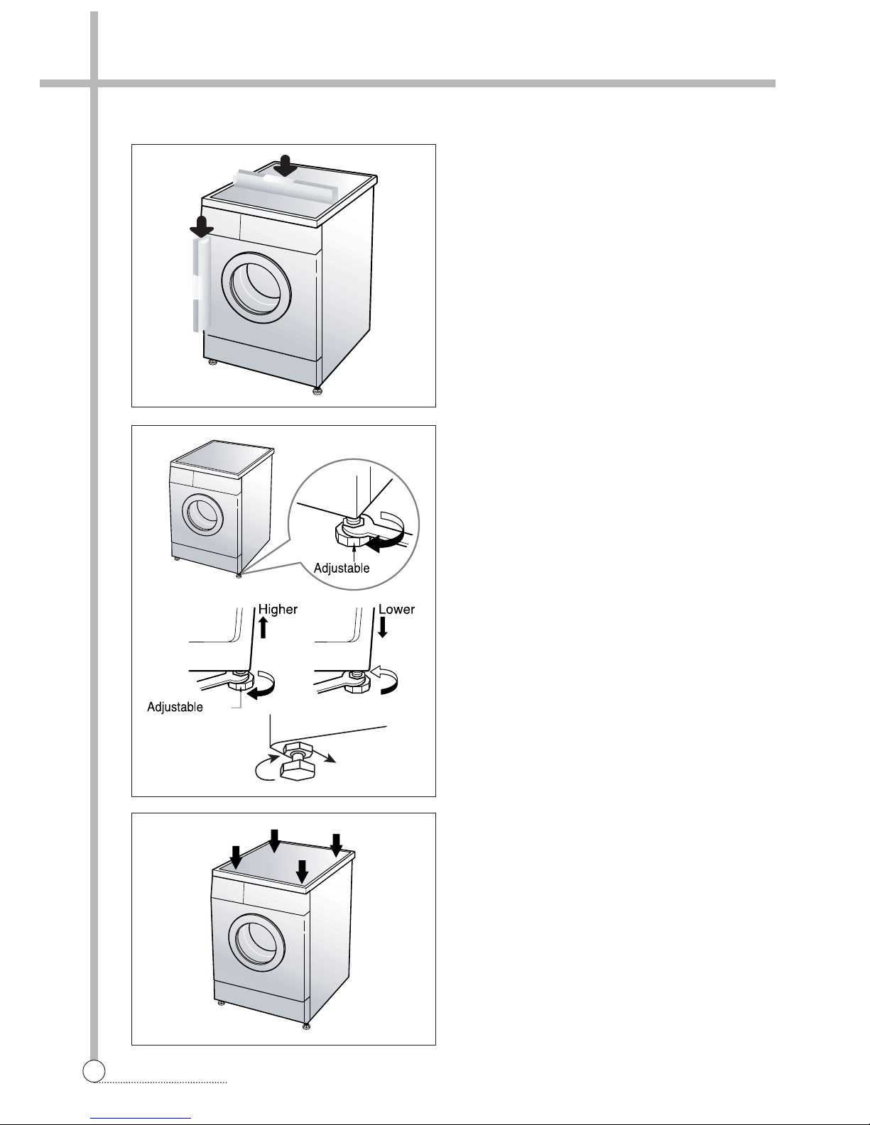
■ Level adjustment
1. The level adjustment of the washing machine
prevents excessive noise and vibration.
Install the washing machine on a solid and even
floor surface, if possible, in a corner of the room.
Note: The wooden floor may cause excessive
vibration.
2. If the floor is uneven, adjust the adjustable leg as
the following.
(Do not insert pieces of wood etc. under legs.)
• Please check whether there is any gap between
four adjustable legs and the floor.
• Turn adjustable legs by the enclosed spanner in
order to adjust the level of the washing machine.
• Make it sure that there is no swaying of the
washing machine and check that the washing
machine is even completely. (use a spirit level)
• After the level adjustment is finished, turn fixing
nuts up tightly so that the washing machine
maintains the adjustment.
leg
leg
Fixing Nut
❈ Diagonal Check
When pushing down the edges of the washing
machine top plate diagonally, the machine should
not move up and down at all.
(Please, check both of two directions)
If machine rocks when pushing the machine top
plate diagonally, adjust legs again.

3. MAINTENANCE
13
MAINTENANCE
❈ Before cleaning the washer interior, unplug the electrical power cord avoid electrical shock hazards.
■ Cleaning your washer
1. Exterior
Proper care of your washer can extend its life.
The outside of the machine can be cleaned with warm water and a neutral non abrasive household detergent.
Immediately wipe off any spills. Wipe with damp cloth.
Try not to hit surface with sharp objects.
• Do not use methylated spirits, diluents or similar products.
2. Interior
Dry around the washer door opening, flexible gasket and door glass.
Run washer through a complete cycle using hot water.
Repeat process if necessary.
• Remove hard water deposits using only cleaners labeled as washer safe.
■ Cold condition
If the washer is stored in an area where freezing may occur or moved in freezing temperature,
follow these instructions to prevent damage to the washer.
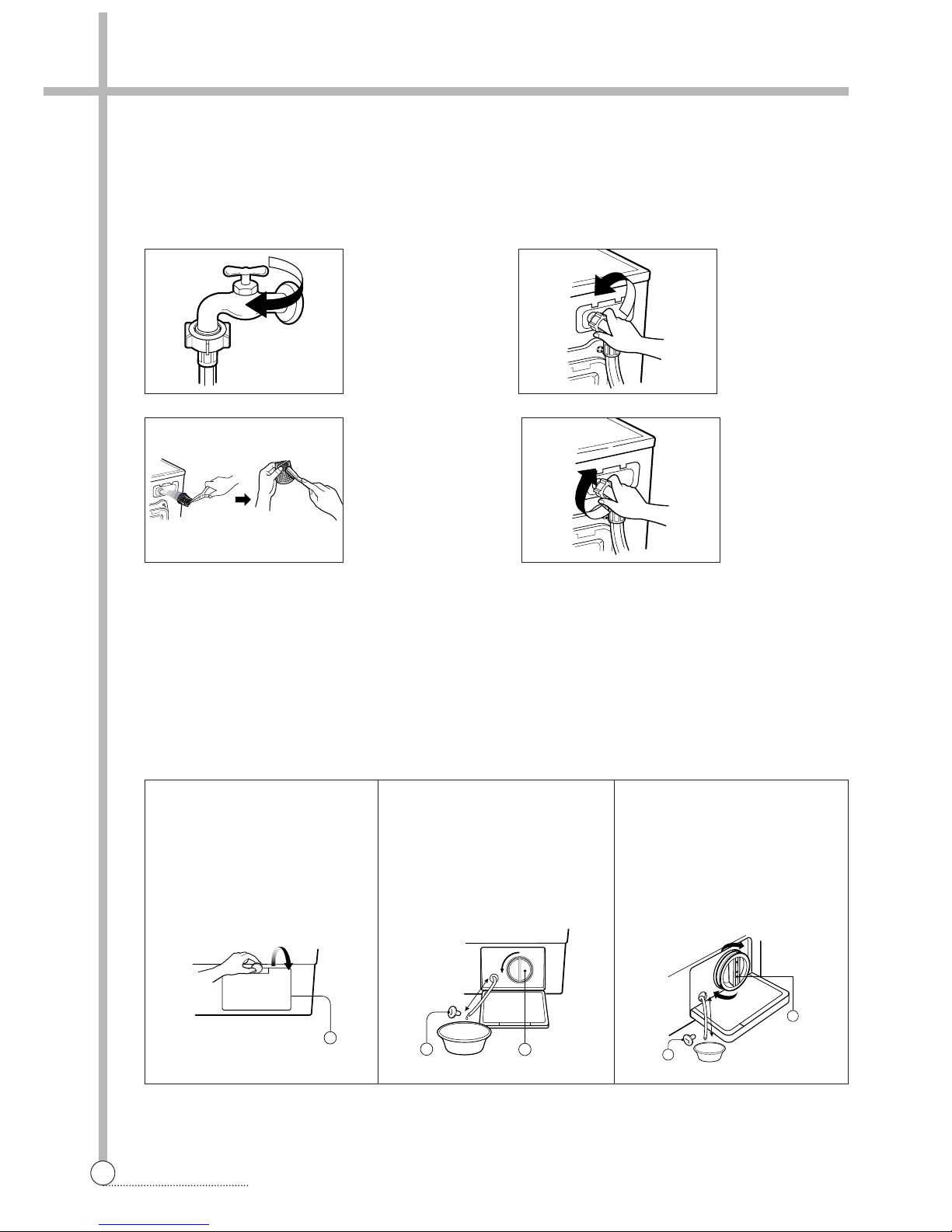
1. Turn off water supply tap.
2. Disconnect hoses from water supply and drain water from hoses.
3. Plug electrical cord into a properly grounded electrical outlet.
4. Add 1gallon(3.8L) of nontoxic recreational vehicle(RV) antifreeze into empty wash drum.
Close the door.
5. Set spin cycle and let washer spin for 1minute to drain out all water.
6. Unplug eletrical power cord, dry the drum interior, and close the door.
7. Remove detergent case and dry excessive water from the compartments.
8. Store washer in an upright position.
9. To remove antifreeze from washer after storage, run empty washer through a complete cycle using detergent.
Do not add wash load.
14
MAINTENANCE
■ Cleaning the water inlet filter
• "IE" error message will blink on the control panel when water does not enter the detergent drawer.
• If your water is very hard or contains traces of lime deposit, the water inlet filter may become clogged.
• It is therefore a good idea to clean it from time to time.
■ Cleaning the drain pump filter
• The drain filter collects threads and small objects left in the laundry.
• Check regularly that the filter is clean to ensure smooth running of your machine.
CAUTION Be careful when draining if the water is hot.
1. Turn off the
water tap.
2. Unscrew the
water inlet
hose.
3. Clean the filter
using a had
bristle brush.
4. Tighten up the
inlet hose.
1. Open the lower cover(1) by
using a coin. Turn the cap
hose(2) to pull out the hose.
Pull out the hose maximally.
(About 13~14cm.)
2.
Unplug the cap hose(2), allowing
the water to flow out. At this time
use a vessel to prevent water
flowing on to the floor. When
water does not flow any more, turn
the pump filter(3) open to the left.
3. Remove any foreign material
from the pump filter(3). After
cleaning, turn the pump filter
clockwise and insert the cap
hose(2) to the original place.
Close the lower cover.
1
100
2
3
about
13~14cm
2
3
about
13~14cm
■ Cleaning the water inlet filter
• "IE" error message will blink on the control panel when water does not enter the detergent drawer.
• If your water is very hard or contains traces of lime deposit, the water inlet filter may become clogged.
• It is therefore a good idea to clean it from time to time.
15
MAINTENANCE
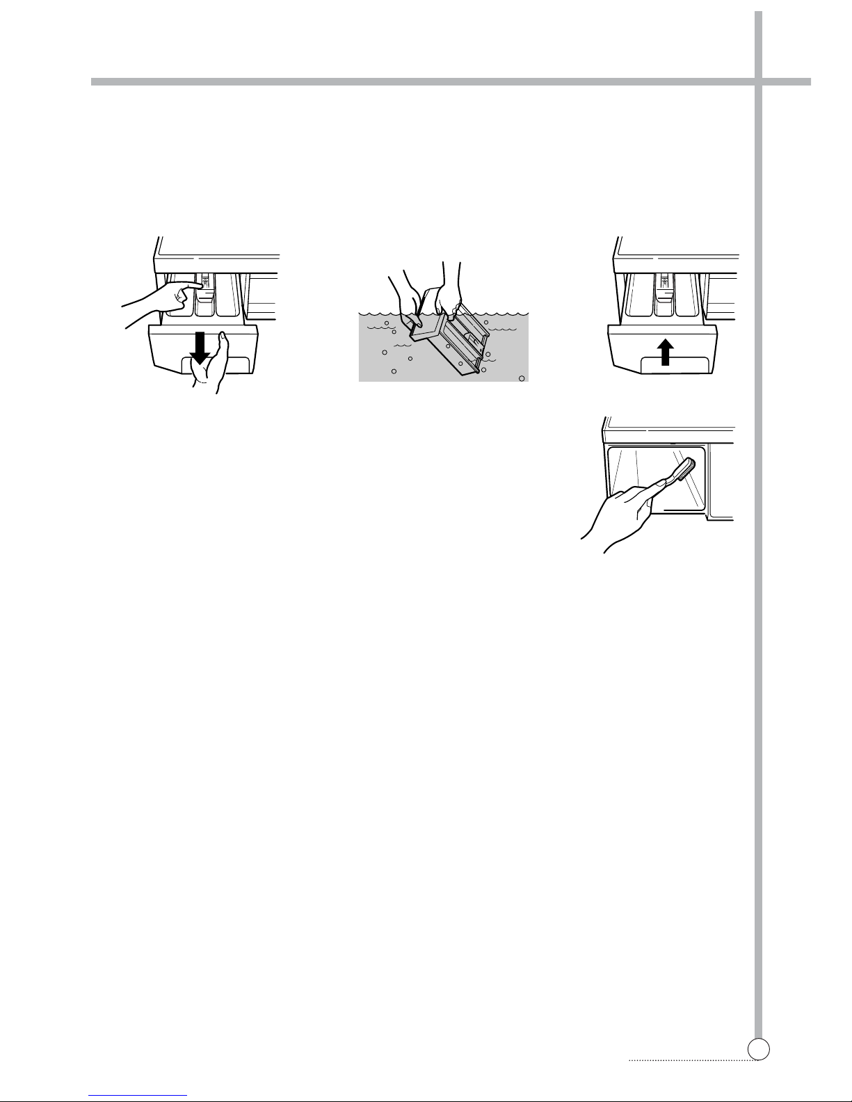
■ Cleaning the detergent case
❈After a while detergents and fabric softeners leave a deposit in the detergent case.
• It should be cleaned from time to time with a jet of running water.
•If necessary it can be removed completely from the machine by pressing the catch downwards and by pulling it out.
• To facilitate cleanling, the upper part of the fabric softener compartment can be removed.
Inlet box recess
❈Detergent can also accumulate inside the recess which should be cleaned
occasionally with an old toothbrush.
• Once you have finished cleaning, replace the detergent case and run a rinse
cycle without laundry.
MAX
max
MAX
max
■ Cleaning the washing drum
• If you live in a hard water area, limescale may continuously build up in places where it cannot be seen and thus
not easily removed.
• Over time the build up of scale clogs appliances, and if it is not kept in check these may have to be replaced.
• Although the washing drum is made of stainless steel, specks of rust can be caused by small metal articles (paper
clips, safety pins) which have been left in the drum.
• The washing drum should be cleaned from time to time.
• If you use descaling agents, dyes or bleaches, make sure they are suitable for washing machine use.
❈Descaler may contain chemicals that may damage part of your washing machine.
❈Remove any spots with a stainless steel cleaning agent.
❈Never use steel wool.
■ Cleaning the detergent case
❈After a while detergents and fabric softeners leave a deposit in the detergent case.
• It should be cleaned from time to time with a jet of running water.
•If necessary it can be removed completely from the machine by pressing the catch downwards and by pulling it out.
• To facilitate cleanling, the upper part of the fabric softener compartment can be removed.

4. DIRECTION FOR DISASSEMBLY
16
DIRECTION FOR DISASSEMBLY
DOOR LOCK SWITCH
1) Open the door and remove the gasket clamp. 2) Remove the gasket from the front cabinet.
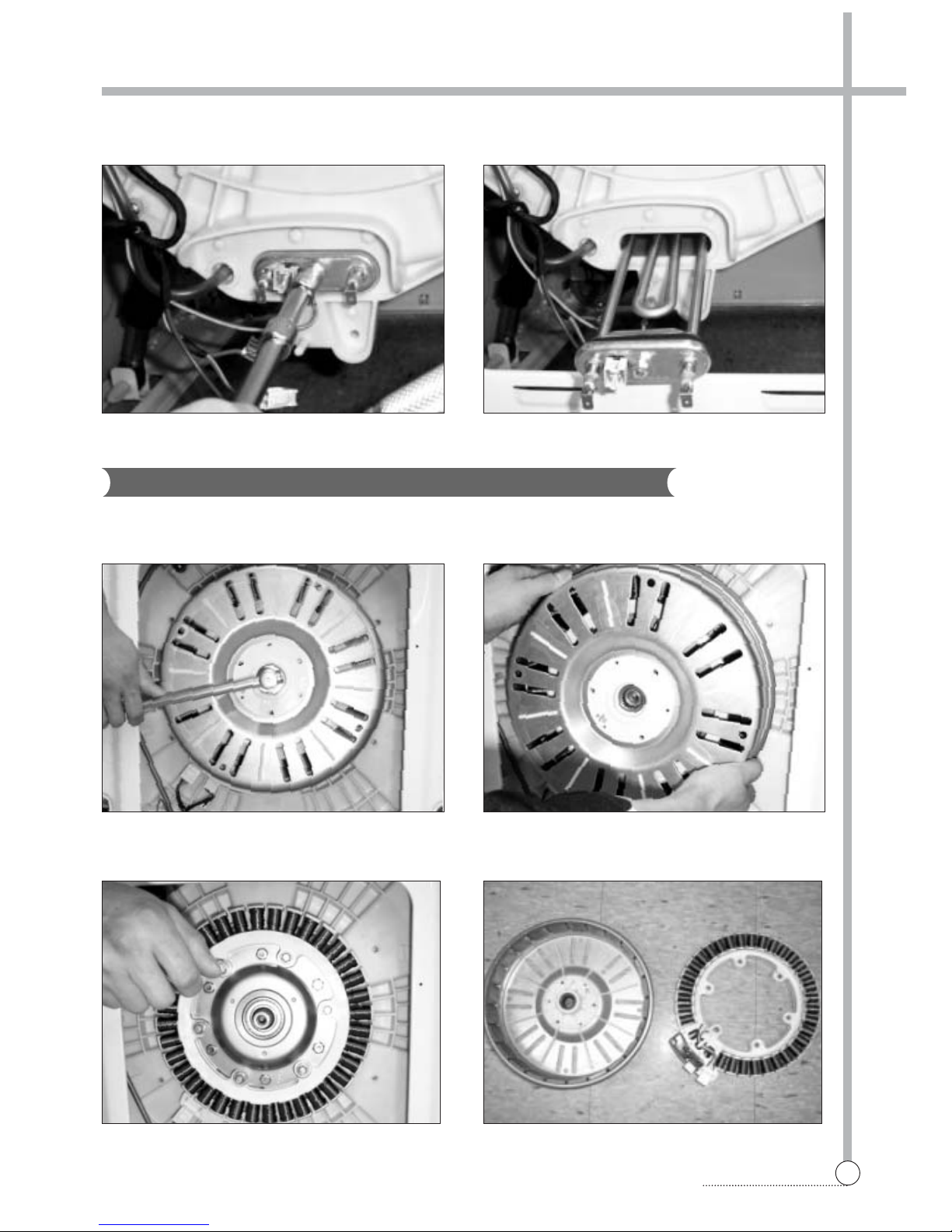
HEATER AND THERMISTOR
1) Remove five screws on the COVER B and separate
the COVER B from washing machine.
2) Remove the connectors of the HEATER.
3) Remove two screws, and remove the door lock
switch.
17
DIRECTION FOR DISASSEMBLY
3) Remove the nut using the 10mm hex wrench and
remove the earth terminal from the HEATER.
4) Loose the nut of the HEATER and pull out the
HEATER.
BLDC MOTOR
1) Remove the nut using the 17mm hex wrench. 2) Pull out the ROTOR.
3) Remove six screws using the 10mm hex wrench and
connectors from the STATOR.
4) Separate the STATOR from the TUB.
18
DIRECTION FOR DISASSEMBLY
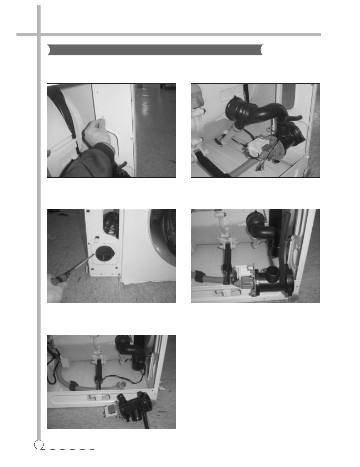
DRAIN PUMP
1) Lay the right side of the washer on the floor, and
remove the lower panel by pressing six sanp fits.
2) Remove connectors.
3) Remove the screw, and remove the drain pump from
the lower frame.
4) Remove the drain hose.
5) Remove the inner drain hose, and remove the drain
pump.
5. EXPLODE VIEW AND PARTS LIST
19
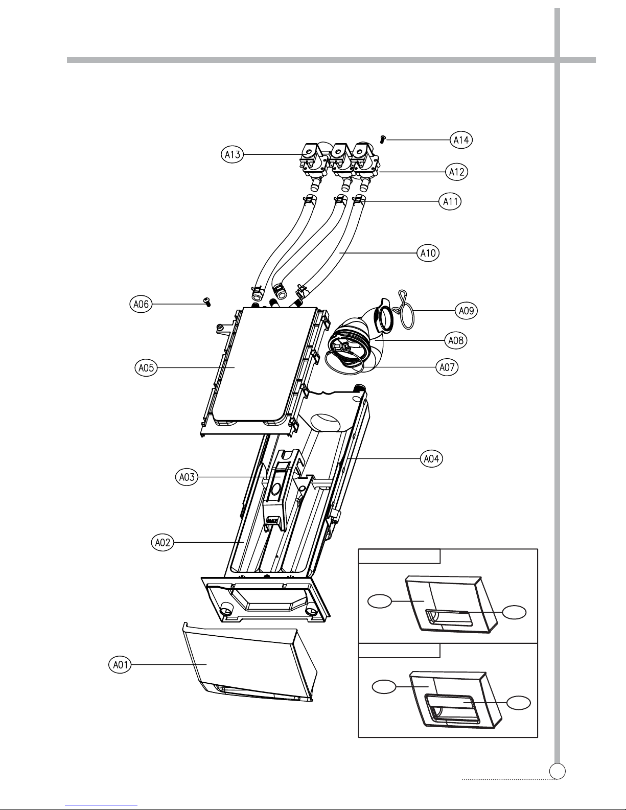
EXPLODE VIEW AND PARTS LIST
■ BOX INLET AS
A01
A15
DWD-F1X6X SERIES
A01
A15
DWD-F1X7X SERIES
20
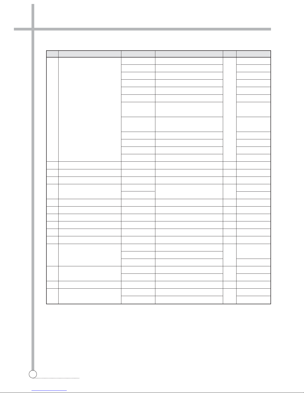
EXPLODE VIEW AND PARTS LIST
3612608700 ABS DWD-F1X11(2)
3612608710 ABS + SPRAY DWD-F1X13
3612608900 ABS DWD-F1X21(2)
3612608910 ABS + SPRAY DWD-F1X23
3612609700 ABS DWD-F1X31(2)
3612609710 ABS + SPRAY DWD-F1X33
A01 HANDLE CASE 3611148000 HIPS, D-FU124'S 1 DWD-F1X41(2)
(CASE HANDLE) DWD-F1X51(2)
3611148001 ABS + SPRAY DWD-F1X43
DWD-F1X53
3611149500 D-F'SERIES 6TH, ABS DWD-F1X61(2)
3611149510 ABS + SPRAY DWD-F1X63
3611149600 D-F'SERIES 7TH , ABS DWD-F1X71(2)
3611149610 ABS + SPRAY DWD-F1X73
A02 CASE DETERGENT 3611140300 PP 1
A03 CAP SOFTENER 3610916600 PP 1
A04 BOX INLET 3610526500 PP 1
A05 NOZZLE AS
3618103510 NOZZLE TOP + NOZZLE UNDER
1
COLD
3618103500 COLD+HOT
A06 SCREW TAPPING 7122402011 T2S TRS 4x20 MFZN 1
A07 CLAMP AS 3611203200 ID=60,WIRE+GUIDE+BOLT+NUT 1
A08 HOSE INLET 3613267200 EPDM U-TRAP 1
A09 CLAMP HOSE I 3611201400 HSW3, D2.6, MFZN, ID=38 1
A10 HOSE WATER SUPPLY 3613270900 EPDM, ID9.5, OD14.5, L=225 2(3) COLD(+HOT)
A11 CLAMP HOSE 3611205800 100H, ID=13.8 W=10.0 0.9T 4(6) COLD(+HOT)
3615414900 220-240V 2-WAY PP/BRACKET COLD VALVE
A12 VALVE INET 3615414910 220-240V 2WAY NYLON VDE
3615416821
220-240V.VDE.BITRON.2WAY + DR TECH
COLD VALVE(EU)
A13 VALVE INLET
3615414800 220-240V,50/60Hz,1WAY HOT VALVE
3615416720
220-240 50/60-1WAY,HOT,BITRON,VDE
HOT VALVE(EU)
A14 SCREW TAPTITE 7272400811 TT3 TRS 4X8 MFZN 2(4) COLD(+HOT)
A15 DECO CASE HANDLE
3611698000 D-F'SERIES 6TH ,ABS DWD-F1X6X
3611698400 D-F'SERIES 7TH , ABS DWD-F1X7X
No. PART NAME PART CODE SPECIFICATION Q'TY REMARK
1
1
1
 Loading...