

Page 1

CONTENTS
1. Specifications................................................................................................2
2. Operation.....................................................................................................3
3. Wiring Diagram..........................................................................................10
4. Refrigerant Cycle.........................................................................................11
5. Control Block Diagram.................................................................................12
6. Circuit Diagram..........................................................................................13
7. Trouble Shooting..........................................................................................16
8. Key Components of Electronic Circuit............................................................26
9. Disassembly Instructions ...............................................................................28
10. Exploded Diagram and Parts List...................................................................30
Contents
Page 2
2
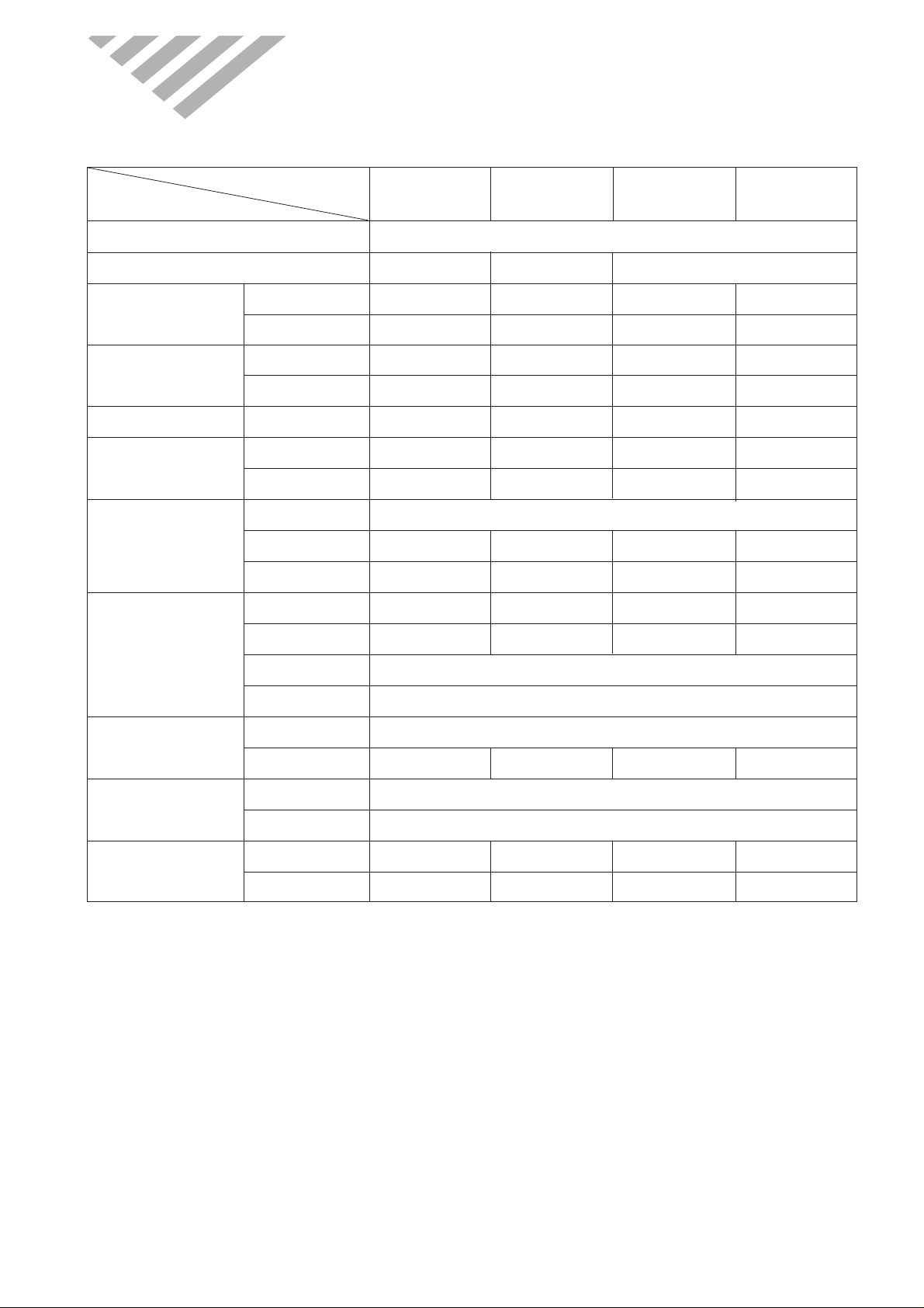
1. SPECIFICATIONS
ITEM
MODEL
DWC-121R DWB-121R DWA-121R DWA-150R
Function Cooling only
Power source AC 115V, 60Hz AC 220~240V, 50Hz AC 208~220V, 60Hz
Cooling Capacity
Btu/h 12,100 Btu/h 12,000 Btu/h 12,000 Btu/h 14,018 Btu/h
Kcal/h 3,050 Kcal/h 3,024 Kcal/h 3,024 Kcal/h 3,533 Kcal/h
Energy Efficiency Ratio
Btu/wh 10.1 Btu/wh 9.5 Btu/wh 10.2 Btu/wh 9.4 Btu/wh
Kcal/wh 2.55 Kcal/wh 2.39 Kcal/wh 2.57 Kcal/wh 2.38 Kcal/wh
Dehumidification Pts/h 3.40 Pts/h 3.30 Pts/h 3.61 Pts/h 4.04 Pts/h
Electrical Data
Power Input 1,200 W 1,263 W 1,175 W 1,487 W
Running Current 11.5A 5.6A 5.5A 6.7A
Compressor
Type Rotary
Model QK164CN12 QK196PN22B QK164KN12 QJ196KC23B
Capacitor 40µF/370VAC 35µF/400VAC 25µF/370VAC 25µF/370VAC
Model AM12DWD10-1 A2929CA01A AM12DWD12-1 AM12DWD11-1
Motor
Capacitor 12µF/370VAC 5µF/400VAC 5µF/370VAC 4µF/370VAC
Indoor-Fan Blower-Fan
Outdoor-Fan Propeller-Fan
Refrigerant(R-22)
Control Capillary
Charge Q’ty 680g 700g 740g 790 g
Dimensions
Unit(W x H x D) 23.6(W) x 14.9(H) x 21.0(D) inch (600(W )x 380(H) x 535(D) mm)
Packing(W x H x D) 26.1(W) x 18.1(H) x 22.6(D) inch (663(W )x 460(H) x 573(D) mm)
Weight
Net Weight 88 lbs (38.8Kg) 90.2 lbs (39.8Kg) 88 lbs (38.8Kg) 92 lbs (42Kg)
Gross Weight 89 lbs (40.3 Kg) 97.5 lbs (43Kg) 89 lbs (40.3 Kg) 96 lbs (43.5Kg)
Page 3
4
2
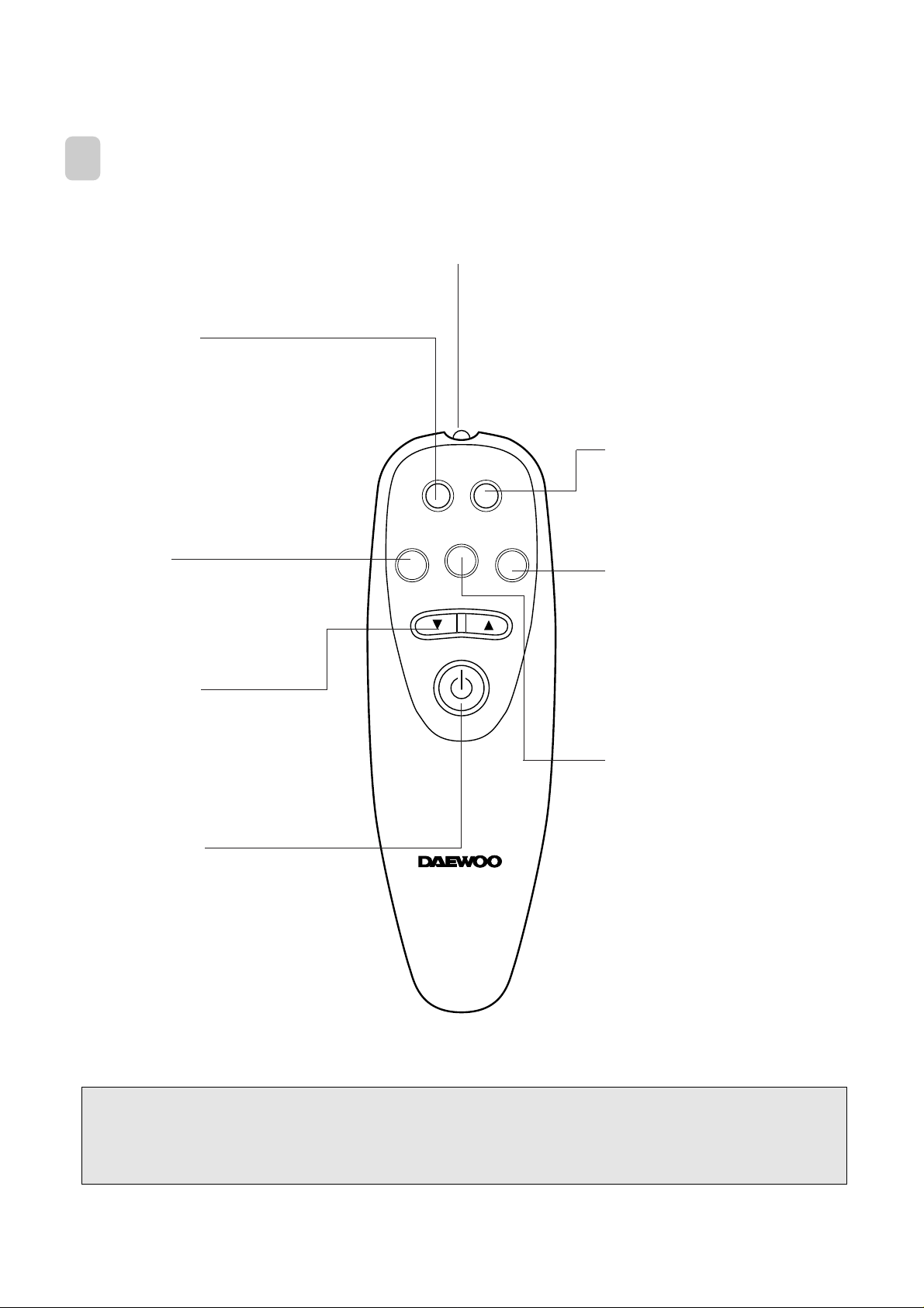
REMOTE CONTROLLER
REMOCON SIGNAL TRANSMITTER
TIMER/CANCEL
• Everytime you push this button,
timer is set as follow.
(1Hr→2Hr→3Hr→4Hr→5Hr→6Hr→8
Hr→10Hr→12Hr→16Hr→20Hr→24Hr
→CANCEL).
After the unit is timed, if this button is
pushed, timer is canceled.
SLEEP
• SLEEP mode is selected as
follow. (L1→L2→Cancel)
MODE
• Everytime you push this button,
it is selected as follow.
(COOLING→TURBO→FAN→
COOLING)
AUTO SWING
• Everytime you push this button,
the auto swing mode is toggled.
TEMPERATURE
• It is the button to set the room in
the desired room temp.
The temp can be set within a
range from 16°C (60°F) to 32°C
(90°F) by 1°C (1°F)
POWER ON/OFF
• To turn the unit ON, push this
button. To turn the unit OFF,
push this button, again.
FAN SPEED
• Everytime you push this button,
it is selected as follow.
(High→Mid→Low→High)
TIMER/
CANCEL
FAN SPEED
TEMP
SLEEP
MODE
AUTO
SWING
✽ Do not use the REMOTE CONTROLLER before the lamp lights. If use, the “°F ” temperature display can
change to “°C ” temperature display (only “°F” temperature display model).
Page 4
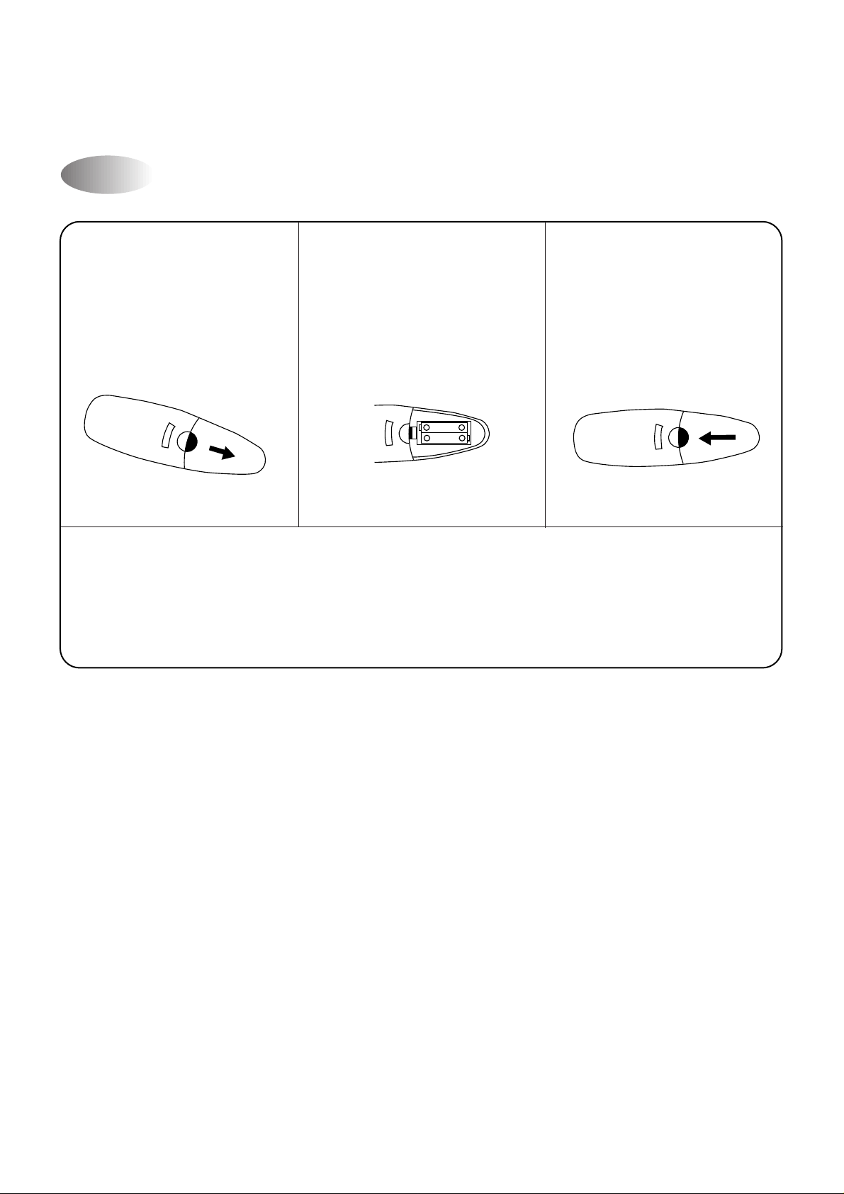
Replacing Batteries
6
Remove the COVER from
the back of the remote
controller.
• Slide the cover
according to the arrow
direction
Insert two battaries.
• Be sure that the (+) and
(–) directions are correct
• Be sure that both batteries
are new
Re-attach the cover.
• Slide it back into position
• Do not use rechargeable batteries such batteries differ from standard dry cells in shape,
dimensions and performance.
• Remove the batteries from the remote controller if the air conditioner is not going to be used for
an extended length of time.
1 2 3
– +
– +
Page 5
8
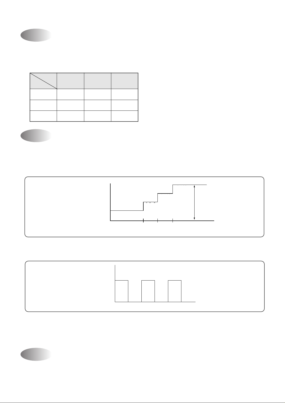
(1) When you are going to sleep, select sleep b utton in remocon and the unit controls the room to the desired
temperature. (The unit will not operate after 4 hour)
(2) For changing the temperature.
• Mode I (L1)
• The unit will not operate after 4 hour.
• Mode II (L2)
• The unit will not operate perfectly after 10 hour .
(3) To cancel sleep mode, press the SLEEP button again or press the MODE b utton once. :the SLEEP indicator will
disappear in the display.
In normal operation, there is a time delay of three minutes between turn off and turning back on including
initial power up.
Sleep Mode
3min. Time Delay of Compressor
0 0.5 1.0 HOUR
SET TIME
Desired
Difference
desired temperature
between room
temperature (°C)
0.5°C
0.5°C
0.5°C
Temperature
Fan Speed
(1) Motor speed (high speed, normal speed, low speed).
(2) Remote controller setting fan speed. (H, M, L)
(3) Relation of operating mode between fan speed.
FAN ONLY COOL TURBO
H H H H
M M M -
L L L -
1
1
1
2hr 2hr 2hr 2hr 2hr
Desired
+1˚C
Temperature
+1˚C
SET ON
SET OFF
1°C
1°C
1°C
Page 6

10
3. WIRING DIAGRAM
Page 7

12
5. CONTROL BLOCK DIAGRAM
Relay 3, 4, 5
Auto Swing
Moter
Fan Motor Compressor
88 LED
Front PCB
Fan mode Lamp
Turbo mode Lamp
Remocon
Signal
Receiver
Cooling mode Lamp
Room Temp Lamp
Desired Temp Lamp
Timer Lamp
Operating Mode
Remote controller
Fan speed
Timer selection
Auto swing
Temp setting
ON/OFF
Sleep
A/D Converter
Beeper
Drive Ic Tr
Room Temp
Sensor
Relay 2 Relay 1
MICOM
Main PCB
DC 12V
DC 12V
DC 12V
DC 5V
DC 5V
Transformer
Page 8

14
NO PART NAME SPEC PART CODE Q’TY REMARK
1 IC MICOM TMP47P443N 13GSHK64-- 1 U1
2 IC DRIVE TD62004AP 13GT62004A 1 U3
3 IC DRIVE TD62783AP 13GT62783A 1 U2
4 IC REGULATOR KIA7812P 1KA7812AP- 1 U4
5 IC REGULATOR KIA7805P 1KA7805AP- 1 U5
6 IC RESET KIA7042P 1KA7042P-- 1 U6
7 FUSE CLIP AFC-520 3107000600 2 FUSE
8 FUSE 125V, 5A 5FULB502L- 1
9 RELAY CS11-12SH 5SC0101128 4 RL2
10 RELAY POWER G4A-1A 5SC010141A 1 RL1
11 RESONATIOR CST8.00MTW 4850L03610 1 OSC1
12 VARISTOR 15G561K D15G561K-- 1 VAR1
13 DIODE 1N4004 DZN4004A-- 4 D1-4
14 DIODE 1N4148 DZN4148A-- 1 D5
15 HEAT SINK 22(H)X23X17 3105797200 1
16 PCB ·‚ Ø , FR-1 3104302100 1
17 BUZZER BM-20K 3105698100 1 BZ
18 TR KRC3198Y TZTC3198Y- 1 Q1
19 WAFER YW396-03AV 3108802500 1 CN4
20 WAFER YPW500-04 3108805500 1 CN5
21 WAFER YW396-03AV(BK) 3108802700 1 CN6
22 WAFER YW500-02V 3108803000 1 CN7
23 WAFER SMW250-02 3108804200 1 CN3
24 WAFER SMW250-08 3108804000 1 CN2
25 WAFER SMW250-10 3108802100 1 CN1
26 WAFER YF254S-02 3108804300 1 TEST
27 PIN GP881206-2 3108803500 2 POWER
28 RESISTOR 300, 1/4W, 5% RD-4K301J- 1 R4
29 RESISTOR 1K, 1/4W, 5% RD-4K102J- 1 R7
30 RESISTOR 5.6K, 1/4W, 5% RD-4K562J- 1 R1
31 RESISTOR 10K, 1/4W, 5% RD-4K103J- 5 R2,3,6,15,16
32 RESISTOR 12.7K, 1/4W, 5% RD-4K1272F 1 R5
33 RESISTOR 300, 1/2W, 5% RD-2K301J- 7 R8-14
34 RESISTOR ARRY 9A 103J RA8K8103J- 1 RA1
35 RESISTOR ARRY 8A 102J RA8K7102J- 1 RA2
36 C-ELEC 1000µF 35V SD CEXE1V108C 1 C2
37 C-ELEC 470µF 25V SD CEXE1E477C 1 C5
38 C-ELEC 100µF 16V SD CEXE1C107C 1 C7
39 C-ELEC 10µF 50V SD CEXE1C106C 1 C10
40 C-ELEC 4.7µF 50V SD CEXE1H475C 1 C11
41 C-CERA 103Z 50VDC CCXE1H103M 1 C13
42 C-CERA 104Z 25VDC CCXE1EH104M 7
C2-4,6,
9,12,13
43 JUMPER 10MM 3109400100 14
J1-6,9,12
J14-16,18
44 JUMPER 6MM 3109400200 4 J7-8,13,17
Part List
● MAIN PCB ASS’Y(3104302300)
Page 9

16
7. TROUBLE SHOOTING
1) Error Code 1(Er)
1 Check the connector of room air thermistor. (or connecting wire)
2 Check soldering of connecting on control P.C .B. (Error of soldering or short)
3 Check the resistance of room air thermistor.
“Press the temperature Ke ys (Up & Down), Error code is displa y ed.”
Self-Diagnostic Function
The power is applied to the unit
Check the voltage between “PO WER ”
and
“RL1
”
of Main P.C.B
4
1
Check the
Breaker or Fuse
Self Diagnostic
function is ON
Check according to
self Diagnostic function
Main P.C.B defect
Check the unit display
is all off?
Press the ON/OFF button of
Remote Control or Front P anel
Is the unit display all off?
Pull out the power plug
and then insert the power plug
after 5 second
Main P.C.B is normal
Recheck from the beginning
Rating voltage more than 90%
Rating voltage
under 90%
No No
No
Yes
Yes
Unit Not Run
Page 10

Page 11

19
Power Supply(1)
DESCRIPTION
DC Po wer Supply in circuit needs +12V and +5V. +12V is used for Compressor Driving Relay, Fan Motor
Driving Relay, Buzzer Driving, Swing Motor Driving Rela y and LED Displa y. AC voltage of secondary Pow er
Transformer is rectified by 4 Diode, and it is filtering by Main Condensor C2.
Filtered DC voltage is about +17V is regulated +12V DC by Regulator IC7812.
And it is regulated +5V DC by Regulator IC7805.
V AR1 is surge filter and C4, C6 is Noise filter.
AC 220V
C1
335
VAR1
POWER
TRANS
+
C2
2200/35V
+
C7
100/16V
2
13
C6
0.1
+
C5
470/25V
C4
0.1
C3
104
7812
2
13
7805
Page 12

21
Room temperature Sensor Input
Temperature
(°C)
No. 15
-10 4.06
0 3.60
15 2.76
25 2.20
40 1.48
Voltage (V)
Table 3-1
Sensor(3)
MICOM
15
R4
300
C13
0.01
R3
12.7K
Vcc
ROOM:PT-K43C
2
1
DESCRIPTION
Number 15 of Micom is Terminal of A/D conv ertor Input.
Room temperature is sensing by change of Thermister Resistance, Micom is put in 5V by ratio between R3
(12.7KΩ) and Room sensor.
Relation between temperature and voltage is f ollowing Table 3-1.
C13 is Noise filter.
Page 13

23
DESCRIPTION
MICOM Po wer is supplied 5V at Number 28 using VDD, Number 6 using Analog Reference of A/D Converter.
C9, C10 is Ripple filter.
Micom Power Supply(5)
MICOM
28
14
6
C10
100µF/16V
C9
104
Vcc
5V
Page 14

25
R3
10K
R2
10K
+5V
MICOM
13
27
˚F/ ˚C
TEST
Function Selecting(7)
Table 9-1
Selection S/W
SHORT OPEN
Function
˚F / ˚C ˚F ˚C
TEST OK NO
DESCRIPTION
Selecting Function is as following table 9-1.
Page 15

27
(3) U2(TD62004AP) DARLINGTON ARRAYS
(4) U7 (7805CT): VOLTAGE REGULATOR (5VDC)
(5) U6 (7812ACT): VOLTAGE REGULATOR (12VDC)
IN1 1 16 OUT 1
IN2 2 15 OUT 2
IN3 3 14 OUT 3
IN4 4 13 OUT 4
IN5 5 12 OUT 5
IN6 6 11 OUT 6
IN7 7 10 OUT 7
GND 8 9 COMMON FREE
WHEELING DIODES
COM
10.5K
7.2K 3K
(Top View)
(Equivalent Circuit)
100K 500
100
100
0.3
10K
6K
500
1K
5K
28K
6K
30pF
2K
5K
200
240
1.4
K
2.7
K
3.3
K
0.19K
INPUT
OUTPUT
GND
SCHEMATIC DIAGRAM
1
2
3
Fin 2 is ground
for Cose 221A.
Case is ground
for Case 1.
10K
INPUT
GND
10K
300
36K
64K
520
26K
60K
29K
20K
20K
40
pF
50K
50 200
300
200
100
16K
210
012
OUTPUT
Pin 1. INPUT
2. GROUND
3. OUTPUT
TSUFFIX
PLAASTIC PACKAGE
CASE 221A
TO-220TYPE
Pin 1. INPUT
2. GROUND
3. OUTPUT
KID65004AP
(Equivalent Ciircuit)
Page 16

29
• HOW TO REMOVE THE FRONT GRILLE
1. Remove the Air Filter from the front grill by pulling up.
2. Remove two screw tapping from front grille.
3. Push the “LATCH position” at the right side of cabinet.
4. Push it again to separate the front grille from the cabinet as shown in Fig. 2
5. Push lower left side of the cabinet and Pull lower left side of the front grille until it is separated from the cabinet
as shown in Fig. 3
6. Push base side of the front grille to upper side until it is separated from the cabinet as shown in Fig. 4
Fig. 1
Push
Screw
Fig. 2
Push
Fig. 3
Fig. 4
Page 17

31
No. CODE COMPONENTS Q’TY SPECIFICATION REMARK
26 7007501211 SCREW HEX 4 5X12MFZN
27 3101802700 FAN PROPELLER 1 ABS + GF20%
28 3102201100 WINDOW KIT FRAME(L) 1 HIPS
29 3102201000 WINDOW KIT FRAME(R) 1 HIPS
30 3100604200 PLATE WINDOW TOP 1 SGCC T1.2
31 3100801400 CABINET AS 1 SGCC T0.8
32 3100604300 BRACKET WINDOW LOWER 2 SGCC T0.8
33 3100604500 BRACKET SILL 2 SGCC T1.6
34 3106600600 SCROLL LOWER 1 EPS
35 3103700100 LEVER VENT 1 PP
36 3103700100 WASHER VENT 1 PP
37 3104600100 RING VENT 1 NBR
38 3106700400 CAM 1 POM
39 7141300611 SCREW TAPPING 4 PAN 3X6
40 3104302300 PCB MAIN AS 1 –
41 3104302400 PCB FRONT AS 1 –
42 3102708900 HARNESS COIL SENSER 1 –
3101396140 POWER CORD 1 WS-001M, 10A 250V DWA-121R/150R(ONLY)
43 3101300600 POWER CORD 1 MP231, 10A 250V DWB-121R(ONLY)
3101300300 POWER CORD 1 KKP-308, 13A 125V DWC-121R(ONLY)
3109503200 CAPACITOR 5/25µF/370VAC DWA-121R(ONLY)
44
3109503300 CAPACITOR 1 5/35µF/370VAC DWB-121R(ONLY)
3109503110 CAPACITOR 1 12/40µF/370VAC L=110MM DWC-121R(ONLY)
3109503410 CAPACITOR 1 4/25 F/370VAC DWA-150R(ONLY)
45 3101200600 CLAMP CAPACITOR 1 SGCC T0.8
46
3108004800 MOTOR SWING 1 120V/60Hz DWC-121R(ONLY)
3966031000 MOTOR SWING 1 200/220V 50/60Hz
DWA,B-121R/DWA-150R(ONLY)
47 3100508510 BOX CONTROL 1 SGCC T0.8
48 3106600500 SCROLL UPPER 1 EPS
49 3103002800 HOLDER SCROLL 2 SGCC T0.8
50 3104409300 PIPE RUBBER BUTYL 1 –
51
3102707500 HANESS COMP AS 1 UL1015–14,BLK,RED,WHT DWC-121C/R(ONLY)
3102708800 HANESS COMP AS 1 UL1015–16,BLK,RED,WHT
DWA,B-121R/DWA-150R(ONLY)
52 3103200500 CAP DRAIN 1 ABS
53 3102708500 HARNESS DISPLAY 1 1 UL1007-22(8COLOR)
54 3102708600 HARNESS DISPLAY 2 1 UL1007-22(10COLOR)
55 3107000400 CLIP THERMO 1 PP
NOTE:
ƒƒRR ¡¡
Ê
A or B or C
Page 18

§§
ö
DWA-121R, DWB-121R, DWC-121R, D WA-150R EXPLODED DIAGRAM
Page 19

S/M NO.: DWC121R010
DAEWOO ELECTRONICS CO ., LTD.
686, AHYEON-DONG MAPO-GU SEOUL, KOREA
C.P.O. BOX 8003 SEOUL, KOREA
TELEX: DWELEC K28177-8
CABLE: “DAEWOOELEC”
FAX: 02) 590-6291
TEL: 02) 360-7114/590-6151~5
http://www.dwe. daewoo.co.kr
PRINTED DATE: APR.1999
Page 20

VISION CREATIVE, INC.
`– ‚ ‡† ·º„fi•˛ 5 ¡ 526
·º¿·”ø 16ˆ
··ªª ··
Á
–˙ œ·
TTEELL
0335-329-8212
MM OO DD EE LL
DWA-121R, DWB-121R, DWC-121R,DWA-150R
BB UU YY EE RR
1´ 6´
2´ 99.4.16(…`⁄ ) 7´
¿
ˇˇ ``⁄⁄
3´ 99.4.21(…`⁄ ) 8´
4´ 99.4.22 9´
5´ 10´
``ƒƒ ˘˘˙˙
99.4.27(Han)-ˆ•´
¿
˛˛……
‚
––
‘ ∞›
MM EE MM OO
¿¿‹‹¶¶Ùˆˆ‡‡
VVIISSIIOONN ··ªª ··Á``¶¶ ˙˙˝¿¿
µ
TEL: 757-9340 FAX: 774-1039
-‚¯·”˙ ˆ„¿¡ …›‰˜» …”˙ ` ……¿ -
 Loading...