

Daewoo DVQ-19H1FC, DVQ-13H2FC, DVQ-19H2FC Service Manual

TV / VCR Combination
CHASSIS : CN-071
MODEL :
DAEWOO ELECTRONICS CO., LTD
DVQ-13H1FC
DVQ-19H1FC
DVQ-13H2FC
DVQ-19H2FC
Service Manual
S/M No:CN071N-010
http : //svc.dwe.co.kr

1
TABLE OF CONTENTS
SAFETY PRECAUTIONS .................................................................................................2
SPECIFICATION ..........................................................................................................5
BLOCK DIAGRAM .......................................................................................................6
IC DESCRIPTION .........................................................................................................8
SYSTEM FEATURE .............................................................................................................................. 9
PIN DESCRIPTION ............................................................................................................................. 10
TROUBLESHOOTING GUIDE .........................................................................................17
NO POWER ..................................................................................................................................... 17
TV PART ........................................................................................................................................... 18
VCR PART ........................................................................................................................................25
ELECTRICAL PARTS LIST ...............................................................................................34
EXPLODED VIEW .........................................................................................................44
2
SAFETY PRECAUTIONS
CAUTION
: DO NOT ATTEMPT TO MODIFY THIS PRODUCT IN ANY WAY.
NEVER PERFORM CUSTOMIZED INSTALLATIONS WITHOUT MANUFACTURER°ØS APPROVAL. UNAUTHORIZED MODIFICATIONS WILL NOT ONLY
VOID THE WARRANTY, BUT MAY LEAD TO YOUR BEING LIABLE FOR ANT
RESULTING PROPERTY DAMAGE OR USER INJURY.
SERVICE WORK SHOULD BE PERFORMED ONLY AFTER YOU ARE THOROUGHLY FAMILIAR WITH ALL OF THE FOLLOWING SAFETY CHECKS AND
SERVICING GUIDELINES. TO DO OTHERWISE, INCREASES THE RISK OF
POTENTIAL HAZARDS AND INJURY TO THE USER.
WHILE SERVICING, USE AN ISOLATION TRANSFORMER FOR PROTECTION
FROM A.C. LINE SHOCK.
SAFETY CHECKS
AFTER THE ORIGINAL SERVICE PROBLEM HAS BEEN CORRECTED, A CHECK
SHOULD BE MADE OF THE FOLLOWING:
SUBJECT:FIRE & SHOCK HAZARD
1. BE SURE THAT ALL COMPONENTS ARE POSITIONED IN SUCH A WAY AS
TO AVOID POSSIBILITY OF ADJACENT COMPONENT SHORTS. THIS IS
ESPECIALLY IMPORTANT ON THOSE MODULES WHICH ARE TRANSPORTED TO AND FROM THE REPAIR SHOP.
2. NEVER RELEASE A REPAIR UNLESS ALL PROTECTIVE DEVICES SUCH AS
INSULATORS, BARRIERS, COVERS, SHIELDS, STRAIN RELIEFS, POWER
SUPPLY CORDS, AND OTHER HARDWARE HAVE BEEN REINSTALLED PER
ORIGINAL DESIGN. BE SURE, THAT THE SAFETY PURPOSE OF THE
POLARIZED LINE PLUG HAS NOT BEEN DEFEATED.
3. SOLDERING MUST BE INSPECTED TO DISCOVER POSSIBLE COLD SOL-
DER JOINTS, SOLDER SPLASHES OF SHARP SOLDER POINTS. BE CERTAIN TO REMOVE ALL LOOSE FOREIGN PARTICLES.
4. CHECK FOR PHYSICAL EVIDENCE OF DAMAGE OR DETERIORATION TO
PARTS AND COMPONENTS, FOR FRAYED LEADS, DAMAGED INSULATION
(INCLUDING A.C. CORD), AND REPLACE IF NECESSARY. FOLLOW ORIGINAL LAYOUT, LEAD LENGTH AND DRESS.
5. NO LEAD OR COMPONENT SHOULD TOUCH A RECEIVING TUBE OR A
RESISTOR RATED AT 1 WATT OR MORE. LEAD TENSION AROUND PROTRUDING METAL SURFACES MUST BE AVOIDED.
6. ALL CRITICAL COMPONENTS SUCH AS FUSES, FLAMEPROOF RESISTOR,
CAPACITORS, ETC. MUST BE REPLACED WITH EXACT FACTORY TYPES.
DO NOT USE REPLACEMENT COMPONENTS OTHER THAN THOSE SPECIFIED OR MAKE UNRECOMMENDED CIRCUIT MODIFICATIONS.
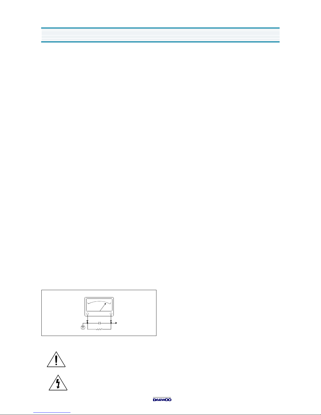
7. AFTER RE-ASSEMBLY OF THE STE ALWAYS PERFORM AN A.C. LEAKAGE
TEST ON ALL EXPOSED METALLIC PARTS OF THE CABINET. (THE CHANNEL SELECTOR KNOB, ANTENNA TERMINALS, HANDLE AND SCREWS) TO
BE SURE THE SET IS SAFE TO OPERATE WITHOUT DANGER OF ELECTRICAL SHOCK. DO NOT USE A LINE ISOLATION TRANSFORMER DURING
THIS TEST USE AN A.C. VOLTMETER, HAVING 5000 OHMS PER VOLT OR
MORE SENSITIVITY, IN THE FOLLOWING MANNER : CONNECT A 1500 OHM
10 WATT RESISTOR, PARALLELED BY A .15 MFD. 150V A.C. TYPE CAPACITOR BETWEEN A KNOWN GOOD EARTH GROUND (WATER POPE, CONDUIT, ETC.) AND THE EXPOSED METALLIC PARTS, ONE AT A TIME.
MEASURE THE A.C. VOLTAGE ACROSS THE COMBINATION OF 1500 OHM
RESISTOR AND .15 MFD CAPACITOR. REVERSE THE A.C. PLUG AND
REPEAT A.C. VOLTAGE MEASUREMENTS FOR EACH EXPOSED METALLIC
PART. VOLTAGE MEASURED MUST NOT EXCEED .75 VOLTS R.M.S THIS
CORRESPONDS TO 0.5 MILLIAMP A.C. NAY VALUE EXCEEDING THIS LIMIT
CONSTITUTES A POTENTIAL SHOCK HAZARD AND MUST BE CORRECTED
IMMEDIATELY.
SUBJECT : GRAPHIC SYMBOLS
THE LIGHTNING FLASH WITH ARROWHEAD SYMBOL,
WITHIN AN EQUILATERAL TRIANGLE, IS INTENDED
TO ALERT THE SERVICE PERSONNEL TO THE PRESENCE OF UNINSULATED “DANGEROUS VOLTAGE”
THAT MAY BE OF SUFFICIENT MAGNITUDE TO CONSTITUTE A RISK OF ELECTRIC SHOCK.
THE EXCLAMATION POINT WITHIN AN EQUILATERAL
TRIANGLE IS INTENDED TO ALERT THE SERVICE
PERSONNEL TO THE PRESENCE OF IMPORTANT
SAFETY INFORMATION ON SERVICE LITERATURE.
SUBJECT : X-RADIATION
1. BE SURE PROCEDURES AND INSTRUCTIONS TO ALL SERVICE PERSONNEL COVER THE SUBJECT OF X-RADIATION. THE ONLY POTENTIAL
SOURCE OF X-RAYS IN CURRENT T.V. RECEIVERS IS THE PICTURE TUBE.
HOWEVER, THIS TUBE DOES NOT EMIT X-RAYS WHEN THE HIGH VOLTAGE IS AT THE FACTORY SPECIFIED LEVEL. THE PROPER VALUE IS
GIVEN IN THE APPLICABLE SCHEMATIC. OPERATION AT HIGHER VOLTAGES MAY CAUSE A FAILURE OF THE PICTURE TUBE OR HIGH VOLTAGE
SUPPLY AND, UNDER CERTAIN CIRCUMSTANCES, AMY PRODUCE RADIATION IN EXCESS OF DESIRABLE LEVELS.
2. ONLY FACTORY SPECIFIED C.R.T ANODE CONNECTORS MUST BE USED.
DEGAUSSING SHIELDS ALSO SERVE AS X-RAY SHIELD IN COLOR SETS.
ALWAYS RE-INSTALL THEM.
3. IT IS ESSENTIAL THAT SERVICE PERSONNEL HAVE AVAILABLE AN ACCURATE AND RELIABLE HIGH VOLTAGE METER. THE CALIBRATION OF THE
METER SHOULD BE CHECKED PERIODICALLY AGAINST A REFERENCE
STANDARD. SUCH AS THE ONE AVAILABLE AT YOUR DISTRIBUTOR.
4. WHEN THE HIGH VOLTAGE CIRCUITRY IS OPERATING PROPERLY THERE
IS NO POSSIBILITY OF AN X-RADIATION PROBLEM. EVERY TIME A COLOR
CHASSIS IS SERVICED, THE BRIGHTNESS SHOULD BE RUN UP AND
DOWN WHILE MONITORING THE HIGH VOLTAGE WITH A METER TO BE
CERTAIN THAT THE HIGH VOLTAGE DOES NOT EXCEED THE SPECIFIED
VALUE AND THAT IT IS REGULATING CORRECTLY. WE SUGGEST THAT
YOU AND YOUR SERVICE ORGANIZATION REVIEW TEST PROCEDURES
SO THAT VOLTAGE REGULATION IS ALWAYS CHECKED AS A STANDARD
SERVICING PROCEDURE, AND THAT THE HIGH VOLTAGE READING BE
RECORDED ON EACH CUSTOMER°ØS INVOICE.
5. WHEN TROUBLESHOOTING AND MAKING TEST MEASUREMENTS IN A
PRODUCT WITH A PROBLEM OF EXCESSIVE HIGH VOLTAGE, AVOID
BEING UNNECESSARILY CLOSE TO THE PICTURE TUBE AND THE HIGH
VOLTAGE SUPPLY. DO NOT OPERATE THE PRODUCT LONGER THAN IS
NECESSARY TO LOCATE THE CAUSE OF EXCESSIVE VOLTAGE.
6. REFER TO HV, B+ AND SHUTDOWN ADJUSTMENT PROCEDURES
DESCRIBED IN THE APPROPRIATE SCHEMATIC AND DIAGRAMS (WHERE
USED).
SUBJECT : IMPLOSION
1. ALL DIRECT VIEWED PICTURE TUBES ARE EQUIPPED WITH AN INTEGRA
IMPLOSION PROTECTION SYSTEM. BUT CARE SHOULD BE TAKEN TO
AVOID DAMAGE DURING INSTALLATION. AVOID SCRATCHING THE
TUBE. OF SCRATCHED REPLACE IT.
2. USE ONLY RECOMMENDED FACTORY REPLACEMENT TUBES.
SUBJECT : TIPS ON PROPER INSTALLATION
1. NEVER INSTALL ANY PRODUCT IN A CLOSED-IN RECESS, CUBBYHOLE OR
CLOSELY FITTING SHELF SPACE, OVER OR CLOSE TO HEAT DUCT, OR IN
THE PATH OF HEATED AIR FLOW.
2. AVOID CONDITIONS OF HIGH HUMIDITY SUCH AS: OUTDOOR PATIO
INSTALLATIONS WHERE DEW IS A FACTOR, NEAR STEAM RADIATORS
WHERE STEAM LEAKAGE IS A FACTOR, ETC.
3. AVOID PLACEMENT WHERE DRAPERIES MAY OBSTRUCT REAR VENTING.
THE CUSTOMER SHOULD ALSO AVOID THE USE OF DECORATIVE
SCARVES OR OTHER COVERINGS WHICH MIGHT OBSTRUCT VENTILATION.
4. WALL AND SHELF MOUNTED INSTALLATIONS USING A COMMERCIAL
MOUNTING KIT, MUST FOLLOW THE FACTORY APPROVED MOUNTING
INSTRUCTIONS. A PRODUCT MOUNTED TO A SHELF OR PLATFORM MUST
RETAIN ITS ORIGINAL FEET (OR THE EQUIVALENT THICKNESS IN SPACERS)TO PROVIDE ADEQUATE AIR FLOW ACROSS THE BOTTOM, BOLTS
OR SCREWS USED FOR FASTENERS MUST NOT TOUCH ANY PARTS OR
WIRING. PERFORM LEAKAGE TEST ON CUSTOMIZED INSTALLATIONS.
5. CAUTION CUSTOMERS AGAINST THE MOUNTING OF A PRODUCT ON
SLOPING SHELF OR A TILTED POSITION, UNLESS THE PRODUCT IS
PROPERLY SECURED.
6. A PRODUCT ON A ROLL-ABOUT CART SHOULD BE STABLE ON ITS MOUNTING TO THE CART. CAUTION THE CUSTOMER ON THE HAZARDS OF TRYING TO ROLL A CART WITH SMALL CASTERS ACROSS THRESHOLDS OR
DEEP PILE CARPETS.
7. CAUTION CUSTOMERS AGAINST THE USE OF A CART OR STAND WHICH
HAS NOT BEEN LISTED BY UNDERWRITERS LABORATORIES. INC. FOR
USE WITH THEIR SPECIFIC MODEL OF TELEVISION RECEIVER OR
GENERICALLY APPROVED FOR USE WITH T.V.S OF THE SAME OR
LARGER SCREEN SIZE.
8. CAUTION CUSTOMERS AGAINST THE USE OF EXTENSION CORDS,
EXPLAIN THAT A FOREST OF EXTENSIONS SPROUTING FROM A SINGLE
OUTLET CAN LEAD TO DISASTROUS CONSEQUENCES TO HOME AND
FAMILY.
10WATT
GOOD EARTH GROUND
SUCH AS THE WATER
PIPE, CONDUIT, ETC.
1500 OHM
A.C. VOLTMETER
PLACE THIS PROBE
ON EACH EXPOSED
METAL PART
0.15 uF
3
SAFETY PRECAUTIONS
CAUTION : Do not attempt to modify this product in any way. Unauthorized modifications will not only void the warranty, but may lead to
your being liable for any resulting property damage or user injury.
Service work should be performed only after you are thoroughly
familiar with all of the following safety checks and servicing guidelines. To do otherwise, increases the risk of potential hazards and
injury to the user.
SAFETY CHECKS
After the original service problem has been corrected, a check should
be made of the following:
SUBJECT : FIRE & SHOCK HAZARD
1. Be sure that all components are positioned in such a way as to
avoid possibility of adjacent component shorts. This is especially
important on those chassis which are transported to and from the
repair shop.
2. Never release a repair unless all protective devices such as insulators, barriers, covers, shields, strain reliefs, and other hardware
have been reinstalled per original design.
3. Soldering must be inspected to discover possible cold solder joints,
frayed leads, damaged insulation (including A.C. cord), solder
splashes or sharp solder points. Be certain to remove all loose foreign particals.
4. Check for physical evidence of damage or deterioration to parts
and components, and replace if necessary follow original layout,
lead length and dress.
5. No leads or components should touch a receiving tube or a resistor
rated at 1 watt or more. Lead tension around protruding metal surfaces must be avoided.
6. All critical components such as fuses, flameproof resistors, capacitors, etc. must be replaced with exact factory types. Do not use
replacement components other than those specified or make
unrecommended circuit modifications.
7. After re-assembly of the set always perform an A.C. leakage test
on all exposed metallic parts of the cabinet, (the channel selector
knob, antenna terminals, handle and screws) to be sure the set is
safe to operate without danger of electrical shock. Do not use a
line isolation transformer during this test. Use an A.C. voltmeter,
having 5000 ohms per volt or more sensitivity, in the following
manner : connect a 1500 ohm 10 watt resistor, paralleled by a 15
mfd. 150V A.C. type capacitor between a known good earth
ground (9water pipe, conduit, etc.) and the exposed metallic parts,
one at a time. Measure the A.C. voltage across the combination of
1500 ohm resistor and 0.15 MFD capacitor. Reverse the A.C. plug
and repeat A.C. voltage measurements for each exposed metallic
part. Voltage measured must not exceed 0.75 volts R.M.S. This
corresponds to 0.5 milliamp A.C. Any value exceeding this limit
constitutes a potential shock hazard and must be corrected immediately.
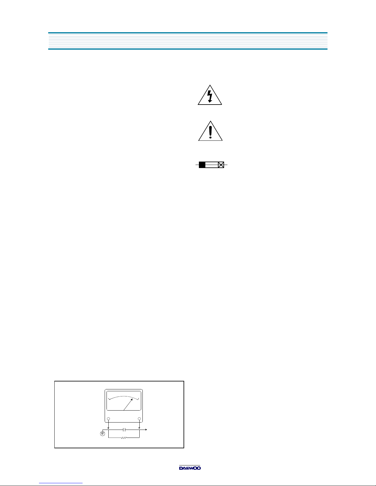
GRAPHIC SYMBOLS :
The lightning flash with arrowhead symbol,
within an equilateral triangle, is intended to alert
the service personnel to the presence of uninsulated “dangerous voltage” that may be of sufficienty magnitude to constitute a risk of electric
shock.
The exclamation point within an equilateral triangle is intended to alert the service personnel
to the presence of important safety information
in service literature.
Fuse symbol is printed on pcb adjacent to the
fuse, with “RISK OF FIRE REPLACE FUSE AS
MARKED”. The symbol is explained in the service manual with the following wording or equivalent.
“CAUTION :
FOR CONTINUED PROTECTION AGAINST FIRE
HAZARD, REPLACE ONLY WITH SAME TYPE (6.3A, 250V)” and
“
ATTENTION
: AFIN D’ASSU UNE PROTECTION PERMANENTE
CONTRE LES RISQUES D’INCENDIE, REMPLACER UNIQUEMENT PAR UN FUSIBLE DE MEME TYPE ET DE ”6.3A, 250V”.
SUBJECT : X-RADIATION
1. Be sure procedures and instructions to all service personnel cover
the subject of X-rays in current T.V. receivers is the picture tube.
However, this tube does not emit X-rays when the high voltage is
at the factory specified level. The proper value is given in the applicable schematic. Operation at higher voltages may cause a failure
of the picture tube or high voltage supply and, under certain circumstances, may produce radiation in excess of desirable levels.
2. Only factory specified C.R.T. anode connectors must be used.
Degaussing shields also serve as X-ray shield in color sets.
Always re-install them.
3. It is essential that the serviceman has available an accurate and
reliable high voltage meter. The calibration of the meter should be
checked perio - dically against a reference standard. Such as the
one available at your distributor.
4. When the high voltage circuitry is operating properly there is no
possibility of an X-radiation problem. Every time a color chassis is
serviced, the brightness should be run up and down while monitoring the high voltage with a meter to be certain that the high voltage
does not exceed the specified value and that it is regulating correctly. We suggest that you and your service organization review
test procedures so that voltage regulation is always checked as a
standard servicing procedure. And that the high voltage reading be
recorded on each customer’s invoice.
5. When troubleshooting and making test measurements in a
receiver with a problem of excessive high voltage, avoid being
unnecessarily close to the picture tube and the high voltage compartment.
Do not operate the chassis longer than is necessary to locate the
cause of excessive voltage.
6. Refer to HV, B+and Shutdown adjustment procedures described in
the appropriate schematic and diagrams(where used).
10WATT
Good earth ground,
such as the water
pipe, conduit, etc.
1500 OHM
A.C. VOLTMETER
Place this probe
on each exposed
metal part.
0.15 uF

4
SAFETY PRECAUTIONS
SUBJECT : IMPLOSION
1. All direct viewed picture tubes are equipped with an integral implosion protection system, but care should be taken to avoid damage
during installation. Avoid scratching the tube. If scratched, replace
it.
2. Use only recommended factory replacement tubes.
SUBJECT : TIPS ON PROPER INSTALLATION
1. Never install any receiver in closed-in recess, cubbyhole or closely
fitting shelf space over, or close to heat duct, or in the path of
heated air flow.
2. Avoid conditions of high humidity such as : Outdoor patio installations where dew is a factor. Near steam radiators where steam
leakage is a factor, etc.
3. Avoid placement where draperies may obstruct rear venting. The
customer should also avoid the use of decorative scarves or other
coverings which might obstruct ventilation.
4. Wall and shelf mounted installations using a commercial mounting
kit, must follow the factory approved mounting instructions. A
receiver mounted to a shelf or platform must retain its original
feet(or the equivalent thickness in spacers) to provide adequate
are flow across the bottom, bolts or screws used for fasteners
must not touch and parts or wiring. Perform leakage test on customized installations.
5. Caution customers against the mounting of a receiver on sloping
shelf or a tilted position, unless the receiver is properly secured.
6. A receiver on a roll-about cart should be stable on its mounting to
the cart. Caution the customer on the hazards of trying to roll a cart
with small casters across thresholds or deep pile carpets.
7. Caution customers against the use of a cart or stand which has not
been listed by underwriters laboratories, inc. For use with their
specific model of television receiver or generically approved for
use with T.V.’s of the same or larger screen size.
5
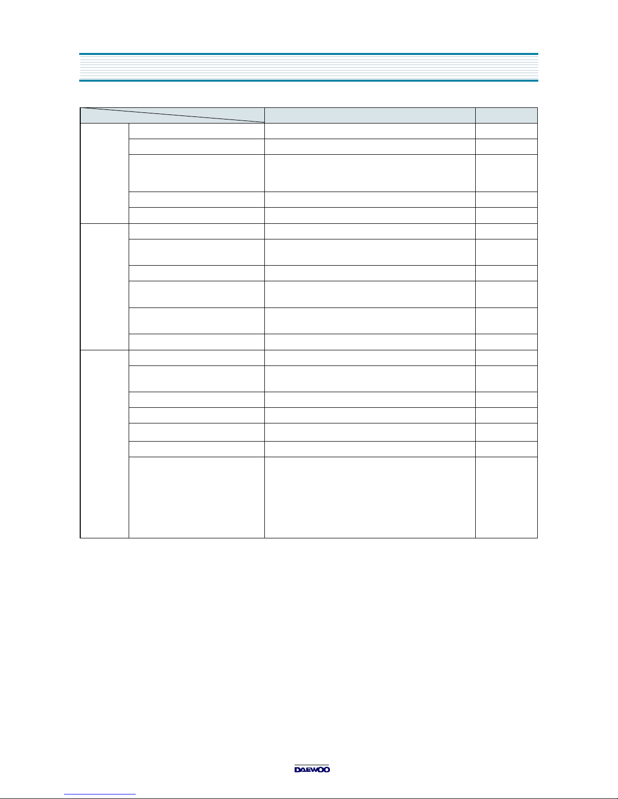
SPECIFICATION
ITEMS MODEL DVQ-13/19H1FC, DVQ-13/19H2FC REMARK
TV
SECTION
STANDARD NTSC-M
TUNING SYSTEM Frequency Synthesizer(FS) Tuning System
TUNING RANGE VHF : 2 - 13(12)
UHF : 14 -69(56)
CATV : 1-125(125)
ANTENNA INPUT IMPEDENCE 75 ohm Unbalanced
AUXILIARY INPUT TERMINAL Front : Video, Audio
VIDEO
SECTION
FORMAT VHS NTSC Standard
VCR SYSTEM Rotary 2-Head Helical Scanning
Monaural System
AUDIO RECORDING SYSTEM Monaural
TAPE SPEED SP:33.35mm/sec; EP:11.12mm/sec
LP:16.67mm/sec PLAY ONLY
INPUT Video :1Vp-p,75 Ohm
Audio :3.8dBm, over 100K Ohm
TIMER PROGRAMING 6 Event/1 Month
GENERAL POWER INPUT AC 120V 60Hz
POWER CONSUMPTION 13=60W
19=70W
SOUND OUTPUT 1.3W
SPEAKER 3W 8 OHM
OPRATING TEMPERATRE
5°C to 40
°C
REMOTE CONTROL R-39A02
SPECIAL FUNTION 3-Language OSD
With CAPTION
Parental Control
K-MECHA
One Touch Record
Repeat Play
Energy Star Power (Stand-By:2W Under)
6
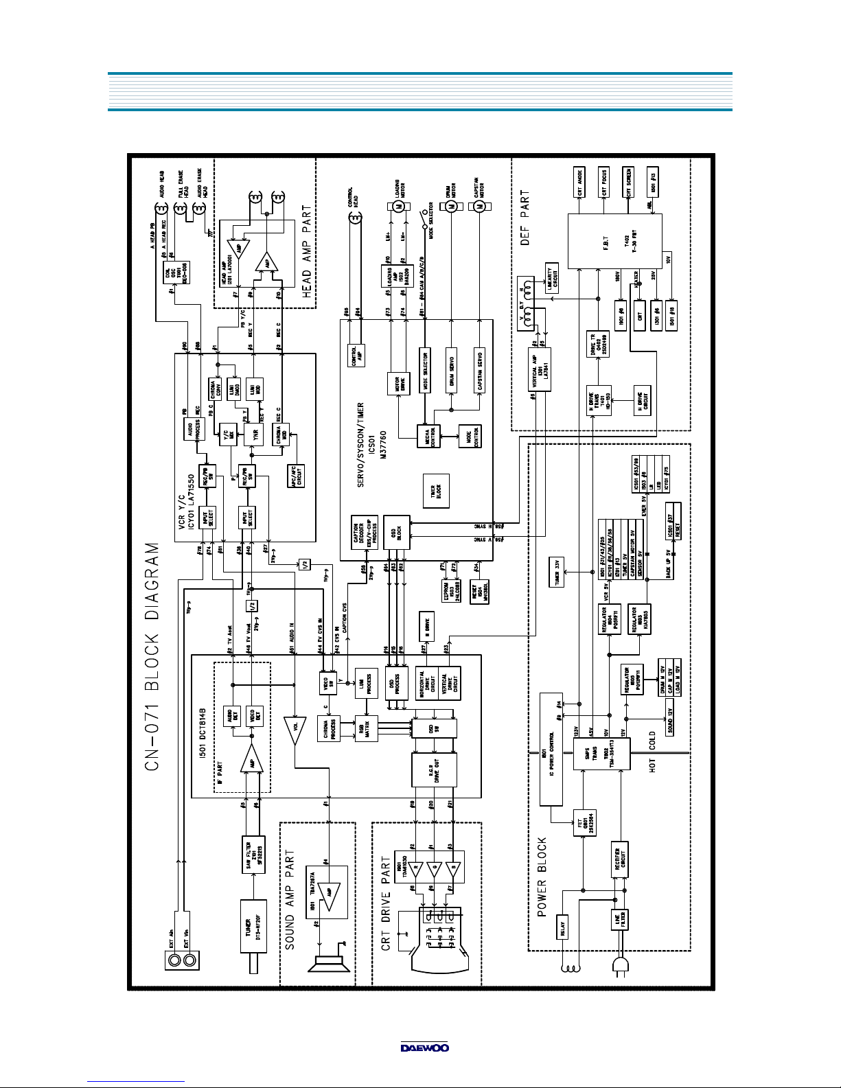
BLOCK DIAGRAM
7
BLOCK DIAGRAM
PH01
8
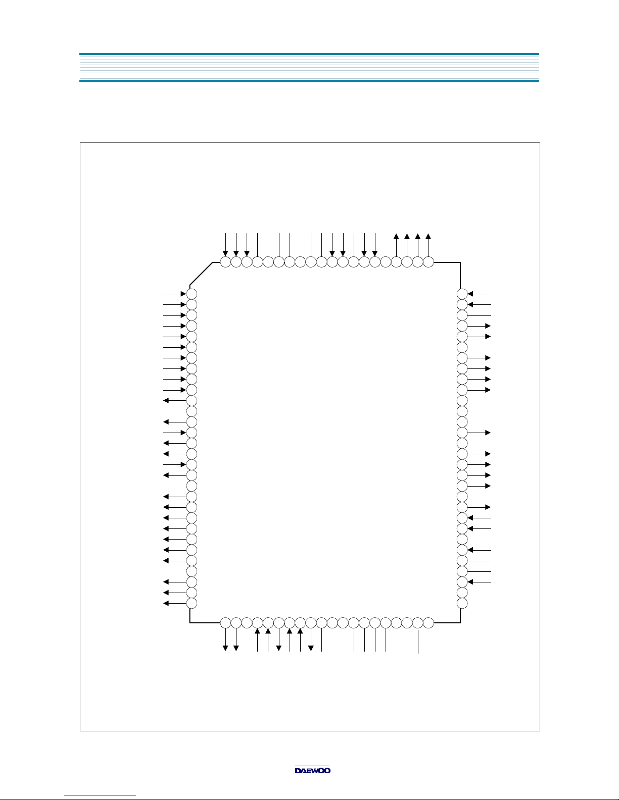
IC DESCRIPTION
ICS01
DW37760MCA-AA1(M37760) : IC TIMER / SYSCON / CTL PROCESSOR
99
100
98 97 96 9495 93 92 91 8990 88 87 86 8485 83 82 81
KEY1
AGC IN
OPTION
DRUM SELECT
PATH ADJUST
VIDEO ENV
END SENSOR
START SENSOR
POWER SAFETY
AFT
CAPSTAN I LIMIT
QV SYNC
REMOCON INPUT
3231 33 34 35 3736 38 39 40 4241 43 44 45 4746 48 49 50
80
79
78
77
76
75
74
73
72
71
70
69
68
67
66
65
64
63
62
61
60
59
58
57
56
55
54
53
52
51
C ROTARY
HEAD AMP SW (4HD)
COMPARATOR ENV (4HD)
V HEAD SW
REC (H)
TRICK (H)
C/DOWN (H)
CAP F/R
SOUND MUTE (H)
AUDIO MUTE (H)
REC LED (H)
T-LED (H)
MONITOR ON (H)
VCR ON
RELAY ON
RESET
Xcin
Xcout
Vcc
Xin
Xout
GND
CLK SELECT
OSD Vcc
FILTER
SLD FILTER
CAPTION
C.V.S
H-SYNC
V-SYNC
OSD BLANK
OSD B
OSD R
OSD G
Y/C SDA
Y/C SCLK
MAIN CLK
MAIN DATA
LD F/R
LD ON
CAP PWM
DRUM PWM
P/W FAIL
RLS
RLT
CAM D
CAM A
CAM B
CAM C
REC SAFETY (L)
CAP FG IN
AMP GND
DRUM FG IN
DRUM PG IN
AMP REF IN
AMP REF OUT
CTL (-)
CTL (+)
CTL AMP OUT
AMP Vcc
ANALOG Vcc
KEY 0
1
2
3
4
5
6
7
8
9
10
11
12
13
14
15
16
17
18
19
20
21
22
23
24
25
26
27
28
29
30
P11(0)/AN8
P7(1)/AN1
P7(0)/AN0
P7(2)/AN2
P7(3)/AN3
P7(4)/AN4
P7(5)/AN5
P7(6)/AN6
P7(7)/AN7
P6(1)/EXORout0 (HASW)
P6(0)/EXORin (ENVS)
P6(2)/EXORout1 (CROT)
P6(3)/RTP02/GEN
P6(4)/RTP03/V
SYNC
P6(5)/RTP10/DA0
P6(6)/RTP11/DA1
P6(7)/AN10/AD
TRG
P5(1)/RTP2
1
P5(0)/RTP2
0
P5(2)/RTP2
2
P5(3)/RTP2
3
P5(4)/RTP2
4
P5(5)/RTP2
5
P5(6)/RTP00(AHSW)
P5(7)/RTP01(VHSW)
P4(7)
P4(6)
P4(5)
P4(4)
P4(3)
P4
(2)
P4(1)
P4(0)
RESET (L)
P3(1)/Xcin
P3
(0)/Xcout
Vcc
Xin
Xout
Vss
P2
(2)/OSC
IN3
P2
(1)/OSC
OUT3
CLK SELECT
P2(0)/OSC
IN2
P1(7)/OSC
OUT2
NUB
P1
(6)/LP
P1(5)/FSCINOSD Vss
P1(4)/CV
IN
P1(0)/V
HOLD
P1(1)/HLP
OSD Vcc
P1(2)
P1(3)
P0(7)/CVIN(EDS)
NUA
P0(6)/H
SYNC/CSYNCIN
P0(5)/V
SYNC
P0(4)/OUT1
P0(3)/OUT2
P0(2)/B
P0(1)/G
P0(0)/R
P10(7)/S
OUT
1
P10(6)/SIN1
P10(5)/S
CLK
1
P10(4)/S
OUT
0/CPFG
MON
P10(3)/SIN0/DRPG
MON
P10(2)/S
CLK
0B/DRFG
MON
P10(1)/S
CLK
0A/SCL
P10(0)/T1/SDA
P9(7)/T5
P9(6)/T4
P9(5)/PWM2
P9(4)/PWM1
P9(3)/PWM0
P9(2)/INT0
P9(1)/RLS
P9(0)/RLT
P8(7)
P8(6)
P8(5)
P8
(4)/INT2
P8
(3)/INT1
P8(2)/CPFGAMP
OUT
CPFG
IN
/CPFGAMP
IN
AMPV
SS
P8
(1)/DRFG
IN
DRPG
IN
/DRPFG
IN
AMPV
REFOUT
AMPV
REFIN
P8(0)/C
CTL-
CTL+
AMPC
CTLAMP
OUT
AMPV
CC
AV
CC
P11(1)
/AN9
M37760
OSC
IN2
OSC
OUT2
NUB
OSD GND
CRT ON(L)

9
IC DESCRIPTION
1. SYSTEM FEATURE
1) The system for TV/VCR tuning is Frequency Synthesis type.
2) VCR SERVO Controller is interior designed.
3) Closed Caption function is interior designed.
4) Parental Control function is interior designed.
5) On Screen Display function is interior designed.
6) Package : 100PIN QFP
7) Tuner (Pre-scaler) : IIC BUS
/PLL IC : TAU 6014-S (SIEMENS)
8) REMOCON : The IC of transmission (MITSUBISHI M50560)
9) EEPROM : 24AT08 (IIC BUS)
10)10-Local Key : A/D input control
(KEY 0 : REC, REW, PLAY, FF, STOP/EJECT)
(KEY 1 : POWER, CH UP/DOWN, VOL UP/DOWN)
11)Option S/W : Port A/D input Option check
12)IF/V/C/D IC : DCT814B (LA76814B)
13)VCR Y/C/A IC : LA71550M
14)DECK MECHANISM : K-MECHA
10
IC DESCRIPTION
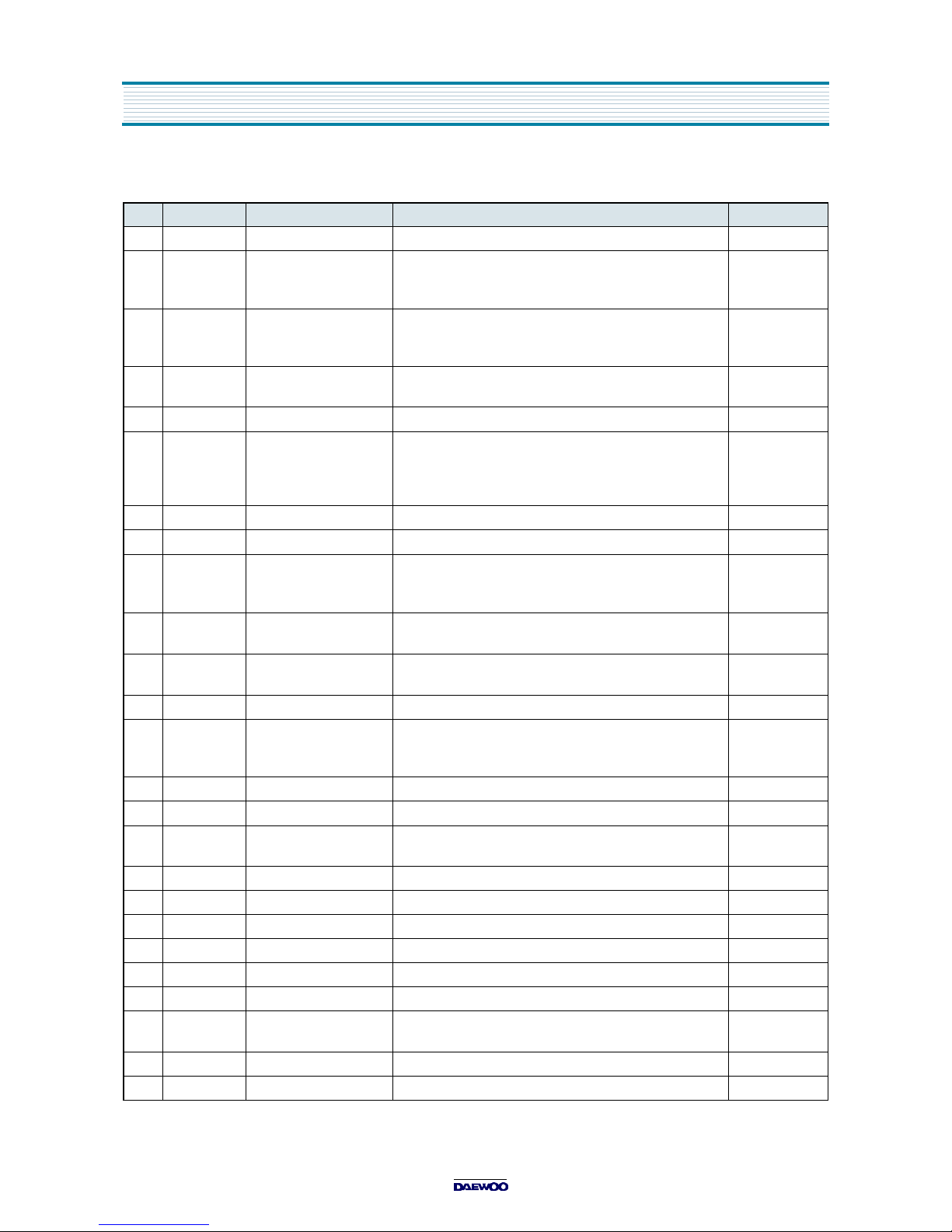
2. PIN DESCRIPTION
Pin Terminal Name Explanation Remarks
1 P11(0) KEY 1 IN Power, Ch up/down, Vol up/down
2 P7(7) AGC IN Connect this port to AGC of Tuner.
Default voltage :3.75V
Variable voltage : 3.25V, 3.5V, 3.75V
3 P7(6) OPTION H(5V) : Parental control
M(2.5V) : Child lock
L(0V) : None
4 P7(5) DRUM SELECT H(5V) : NTSC 4 head
L(0V) : NTSC 2 head
5 P7(4) PATH ADJUST Automatic PATH adjust
6 P7(3) VIDEO ENVELOPE IN Connect this port to 6 pin of IZ01.
Maximum point search DC ENVE input.
Auto tracking restart condition
(SP:2-5V, LP/SLP:1.5-5V)
7 P7(2) END SENSOR IN Tape END sensor detect input. H: Tape end.
8 P7(1) START SENSOR IN Tape START sensor detect input. H: Tape start.
9 P7(0) POWER SAFETY IN Connect this port to 26V of FBT.
FBT protect port.
Detect voltage: 3V under
Z
Hold down
10 P6(7) AFT IN DC voltage that comes from the 10 pin of
DCT814B
11 P6(6) CAPSTAN I LIMIT OUT Limit the current of CAPSTAN MOTOR
Set "L" during PAUSE/STILL
12 P6(5) Not used
13 P6(4) QV SYNC When special play, Quasi Vertical SYNC insert
V SYNC of C.V.S
Special play:
QUE,REV,
STILL,SLOW
14 P6(3) REMOCON INPUT Remote Controller pulse input
15 P6(2) COLOR ROTARY OUT When color MOD/DEMOD, phase shift pulse
16 P6(1) HEAD AMP SW PULSE 4 head option. When special play,
EP head switching pulse
17 P6(0) COMPARATOR ENV 4 head option.
18 P5(7) V HEAD SW PULSE Video head switching pulse(SP head).
19 P5(6) A HEAD SW PULSE 6 head option. Not used
20 P5(5) REC H When recording, set "H"
21 P5(4) TRICK H When special play, set "H"
22 P5(3) CASSETTE DOWN H When cassette insert, light up IR led.
23 P5(2) CAPSTAN F/R Switching forward(H) and reverse(L) of
CAPSTAN MOTOR
24 P5(1) CRT ON L When CRT off, set "H" during 1sec.
25 P5(0) SOUND MUTE H When stand by TV/VCR, set speaker sound mute.

11
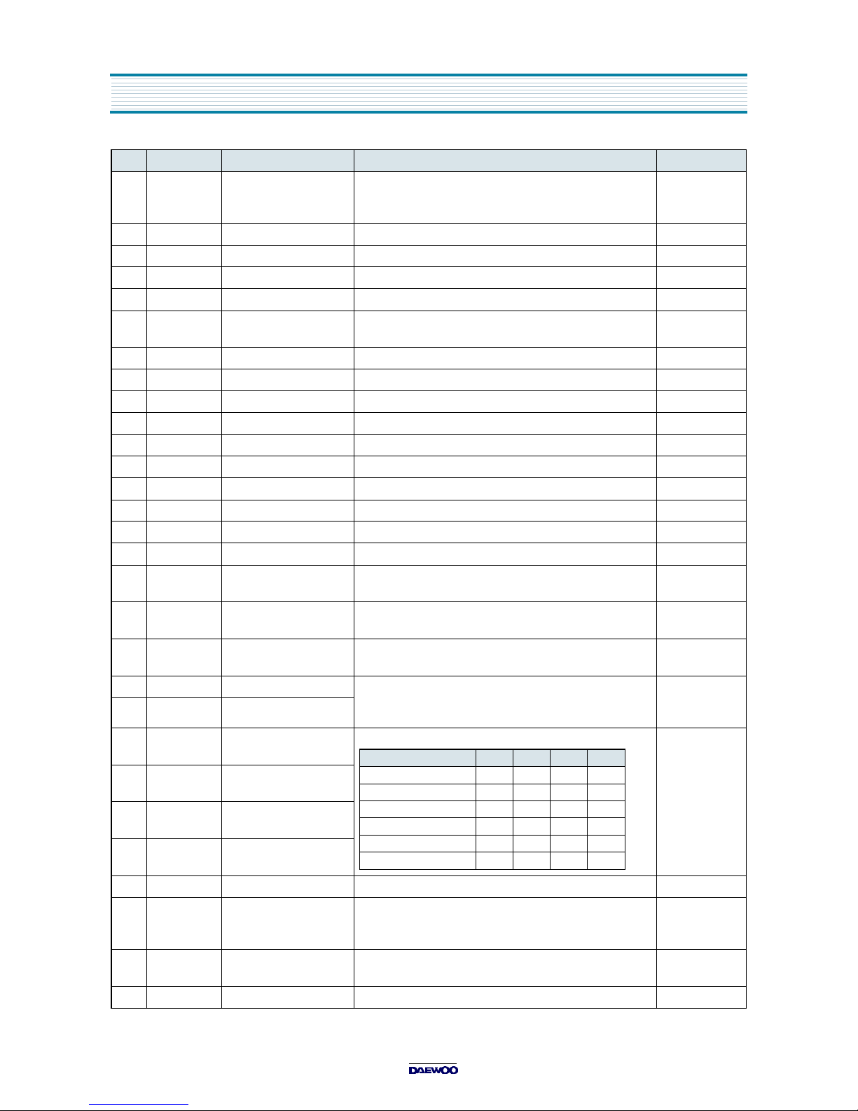
26 P4(7) AUDIO MUTE H Connect this port to 95 pin of ICY01.
When special play, set audio mute.
27 P4(6) Not used
28 P4(5) REC LED H Light up LED(RED) when recording
29 P4(4) TIMER REC LED H Light up LED(GREEN) when ready to
programming record.
30 P4(3) MONITOR ON H When CRT on, set "H".
31 P4(2) VCR ON H Recording when CRT off, set "H"
32 P4(1) RELAY ON H When CRT on, relay on during 1sec.
33 P4(0) Not used
34 RESET RESET(L) RESET
35 P3(1) Xcin It uses 32.768KHz Crystal.
35 pin is input terminal for crystal oscillator
36 pin is output terminal for crystal oscillator
36 P3(0) Xcout
37 Vcc Vcc
Ever +5V(±0.5V). Positive power supply
38 Xin Xin It uses 16MHz Crystal.
38 pin is input terminal for crystal oscillator
39 pin is output terminal for crystal oscillator
39 Xout Xout
40 Vss Vss GND Negative power supply.
41 P2(2) OSCin3 Not used
42 P2(1) OSCout3 Not used
43 CLK SELECT When MICOM to start, decide to 32.768KHz or 16MHz.
Set "L" : 32.768KHz
44 P2(0) OSCin2 It uses LC oscillator.
Set the OSD position.
38 pin is input terminal for LC oscillator
39 pin is output terminal for LC oscillator
45 P1(7) OSCout2
46 NUB NUB GND
47 P1(6) LP H Not used
48 P1(5) FSC IN Not used
49 Vcc OSD Vss GND
50 P1(4) CVS IN Not used
51 P1(3) LECHA Not used
52 P1(2) Not used
53 Vcc OSD Vcc
Ever +5V (±0.5V).
54 P1(1) FILTER Filter terminal for PLL.
55 P1(0) SLD FILTER Filter terminal for SYNC separate.
56 P0(7) C.V.S IN For Caption and Parental control signal detect.
57 NUA NUA GND
58 P0(6) H SYNC IN For OSD horizontal SYNC input
59 P0(5) V SYNC IN For OSD vertical SYNC input
Pin Terminal Name Explanation Remarks
IC DESCRIPTION
12
60 P0(4) OSD BLANK OUT Fast blanking control signal.
Switch TV image signal and
Caption/OSD image signal.
61 P0(3) Not used
62 P0(2) OSD B OUT Blue output terminal of OSD image.
63 P0(1) OSD G OUT Green output terminal of OSD image.
64 P0(0) OSD R OUT Red output terminal of OSD image.
65 P10(7) S DATA IIC data I/O.
Control VCR Y/C, TUNER, EEPROM
66 P10(6) Not used
67 P10(5) S CLOCK IIC clock output
68 P10(4) CAP PG mon Not used
69 P10(3) DRUM PG mon Not used
70 P10(2) DRUM FG mon Not used
71 P10(1) M CLOCK IIC clock output
72 P10(0) M DATA IIC data I/O. Control CHROMA IC
73 P9(7) LD F/R Loading Motor Forward(L)/Reverse(H)
74 P9(6) LD ON When operate Loading Motor, set "H"
75 P9(5) PWM2 Not used
76 P9(4) CAPSTAN PWM Control rotate speed of Capstan Motor.
Period of PWM : 23.4KHz
77 P9(3) DRUM PWM Control rotate speed of Drum Motor. Period of PWM :
23.4KHz
78 P9(2) POWER FAIL Input "L", MICOM is Hold mode.
Backup time approx. 30minute.
79 P9(1) RLS IN Supply reel/Take up reel pulse input terminal.
Use to check the Tape remain or
high speed rewind and fast forward.
80 P9(0) RLT IN
81 P8(7) CAM D CAM detection input terminal.
82 P8(6) CAM C
83 P8(5) CAM B
84 P8(4) CAM A
85 P8(3) Not used
86 P8(2) REC SAFETY SW L Recordable tape insert, "L" input.
If "H" input when insert cassette tape,
then automatic play.
87 CAP PG IN Capstan Pulse Generator signal input.
Feed back Capstan rotation speed.
88 Vss AMPVss GND
Pin Terminal Name Explanation Remarks
MODE A B C D
EJECT L H H H
STAND BY L H L H
REV H H L H
STOP H H H L
PLAY H H H L
FF/REW H L H L
IC DESCRIPTION
13
89 P8(1) DRUM FG IN Drum Frequency Generator signal input.
Feed back Drum rotation speed.
90 DRUM PG IN Drum Pulse Generator signal input.
Feed back Drum rotation phase.
91 AMP REF IN Control pulse AMP reference input terminal.
92 AMP REF OUT Control pulse AMP reference output terminal.
93 P8(0) C AMP filter.
94 CTL- Input control pulse when playing.
95 CTL+ Output control pulse when recording.
96 AMP C AMP condenser.
97 CTL AMP OUT Check Control pulse.
98 Vcc AMP Vcc
Ever +5V (±0.5V).
99 Vcc ANALOG Vcc
Ever +5V (±0.5V).
100 P11(1) KEY 0 IN REC, REW, PLAY, FF, STOP/EJECT
Pin Terminal Name Explanation Remarks
IC DESCRIPTION
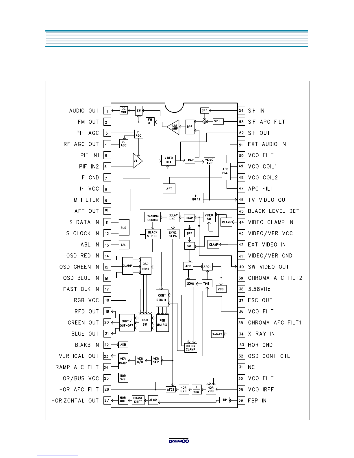
14
IC DESCRIPTION
IC501
DCT814B(LA76814B) : IC VIDEO PROCESSOR
 Loading...