


Service Manual Colour Television
CHASSIS : CP-330 PAL-SECAM SYSTEM
MODEL : DTX-14A1/20A1/21A1 14B1/20B1/21B1 20C1/21C1 14D1/20D1 2066/2166 2072/2172 2075/2195 UK : T140/T142 /T200/T202/T512

DAEWOO ELECTRONICS CO., LTD.
CONTENTS
| Specifications | 2 |
|---|---|
| Block Diagram | 4 |
| Safety Instructions | 5 |
| Assembly View | 6 |
| Installation and Service Adjustment | 9 |
| IC Operation Description | .13 |
| Circuit Description | .36 |
| Printed Circuit Boards | .41 |
| Trouble Shooting Charts | .42 |
| Replacement Parts List | .52 |
| Exploded View | .74 |
| Model | DTX-0000TF | DTX-00001 | гк | DTX-0000VA | DTX-0000TU | |||
|---|---|---|---|---|---|---|---|---|
| Receiving System | PAL-B/G |
P/S-B/G,D
NTSC (A) |
/K
/) |
P/S-B/G
SECAM-L/L' |
PAL-I | |||
| Main Voltage | 230V AC 50Hz | |||||||
|
Power
Consumption |
69W Approx. (14 in
85W Approx. (20 in |
ch)
ch and 21 inch |
) | |||||
| Sound Output | 2.0W Approx. (at 60 | 0% MOD, 10% | 5 THD) | |||||
|
Antenna
Impedance |
75 ohm unbalance | 75 ohm unbalanced | ||||||
| Tuning System | Voltage Synthesis | Tuning System | ||||||
|
Number of
Program |
100 Programs | : | ||||||
| Reception Channel | Refer to the TUNE | R description | ||||||
|
Remote Control
Unit |
With TEXT: R-22 of Without TEXT: R-2 |
or R-23
25 or R-26 |
||||||
|
Screen Size
(Diagonal) |
14": 340mm
20": 480mm 21": 510mm |
|||||||
| Indication |
On-Screen Display
-Program No. (00-99) & Station Name -Sleep (15-120) -Mute & Volume -AV -Normal (Normal I, Normal II, Favourite) -Picture menu (Contrast, Brightness, Colour, Sharpness, Tint (TK model)) -Timer Menu (Clock, On Time, Off Time) -Preset Menu (Auto Search, Search, Fine Tune) -I anguage (English, German, French, Spanish, Italy) |
|||||||
| Aux. Terminal | 21Pin EURO-SC | ART | ||||||
|
Teletext System
(Option) |
4 page memory | FASTEXT (FLC | )F & LIS | т) | ||||
| MODEL | OPTION ID | LANG | UAGES | |||||
| DTX-0000TF | BE01 |
Englis
Spanis |
n, French, Swedish, G
sh, Portuguese, Dutch |
erman, Italian,
, Danish, Norwegian, |
||||
| DTX-0000TU | BE06 |
Catala
Green |
n, Basque, Flemish, C
Iandic, Icelandic, Frisi |
aaeiic, raroese,
an, Latin, Welsh |
||||
| DTX-0000TK | BE04 |
Germa
Hunga |
an, Swedish, Polish, C
arian, Serbocroat, Rur |
zechoslovak,
nanian |
||||
| BE09 | Baltic | Cyrillic | ||||||
Aux Terminal:

21 pin EURO-SCART
| PIN | Signal Designation | Matching Value |
|---|---|---|
| 1 | Audio Out (linked with 3) | 0.5Vrms, Imp < 1KΩ (RF 60% MOD) |
| 2 | Audio In (linked with 6) | 0.5Vrms, Imp > 10KΩ |
| 3 | Audio Out (linked with 1) | 0.5Vrms, Imp < 1KΩ (RF 60% MOD) |
| 4 | Audio Earth | |
| 5 | Blue Earth | |
| 6 | Audio (linked with 2) | 0.5Vrms, Imp > 10KΩ |
| 7 | Blue in | 0.7Vpp±3dB, Imp 75Ω |
| 8 | Slow (Function) Switching | TV: 0-2V, PERI: 9.5-12V, Imp > 10KΩ |
| 9 | Green Earth | |
| 10 | NC | |
| 11 | Green In | 0.7Vpp±3dB, Imp 75Ω |
| 12 | NC | |
| 13 | Red Earth | |
| 14 | NC | |
| 15 | Red In | 0.7Vpp±3dB, Imp 75Ω |
| 16 | Rapid (Blanking) switching | Logic 0: 0-0.4V, Logic 1: 1-3V, Imp 75Ω |
| 17 | Video Earth | |
| 18 | Rapid Blanking Earth | |
| 19 | Video Out | 1Vpp±3dB, Imp 75Ω |
| 20 | Video In | 1Vpp±3dB, Imp 75Ω |
| 21 | Common Earth |
AGRAM


SAFETY INSTRUCTIONS
WARNING: BEFORE SERVICING THIS CHASSIS, READ THE "X-RAY RADIATION PRECAUTION", "SAFETY PRECAUTION" AND "PRODUCT SAFETY NOTICE" BELOW.
1. Excessive high voltage can produce potentially hazardous X-RAY RADIATION. To avoid such hazards, the high voltage must not exceed the specified limit. The nominal value of the high voltage of this receiver is 25.5kv (14": 23.5kv, 21": 26.5kv) at max beam current. The high voltage must not, under any circumstances, exceed 27.5kv (14": 25.0kv, 21": 29.0kv)
Each time a receiver requires servicing, the high voltage should be checked following the HIGH VOLTAGE CHECK procedure on page 9 of this
manual. It is recommended the reading of the high voltage be recorded as a part of the service records. It is important to use an accurate and reliable high voltage metre.
2. The only source of X-RAY RADIATION in this TV receiver is the picture tube. For continued X-RAY RADIATION protection, the replacement tube must be exactly the same type tube as specified in the parts list
-
1. Potentials of high voltage are present when this receiver is operating. Operation of the receiver outside the cabinet or with the back board removed involves a shock bazard from the receiver.
- Servicing should not be attempted by anyone who is not throughly familiar with the precautions necessary when working on high-voltage equipment.
- 2) Always discharge the picture tube to avoid the shock hazard before removing the anode cap.
- Discharge the high potential of the picture tube before handling the tube. The picture tube is highly evacuated and if broken, glass fragments will be violently expelled.
- 2. If any Fuse in this TV receiver is blown, replace it with the FUSE specified in the Replacement Parts List.
- 3. When replacing a high wattage resistor (oxide metal film resistor) in circuit board, keep the resistor 10mm away from circuit board.
- 4. Keep wires away from high voltage of high temperature components.
- This receiver must operate under AC230 volts, 50Hz. NEVER connect to DC supply or any other power or frequency.
Many electrical and mechanical parts in this chassis have special safety-related characteristics. These characteristics are often passed unnoticed by a visual inspection and the X-RAY RADIATION protection afforded by them cannot necessarily be obtained by using replacement components rated for higher voltage, wattage, etc. Replacement parts which have these special safety characteristics are identified in this manual
and its supplements, electrical components having such features are identified by designated symbol on the parts list. Before replacing any of these components, read the parts list in this manual carefully. The use of substitute replacement parts which do not have the same safety characteristics as specified in the parts list may create X-BAY RADIATION.
INSTALLATION & SERVICE ADJUSTMENTS
GENERAL INFORMATION
All adjustments are throughly checked and corrected when the receiver leaves the factory. Therefore the receiver should operate normally and produce proper colour and B/W pictures upon installation. But, several minor adjustments may be required depending on the particular location in which the receiver is operated. This receiver is shipped completely in a card-board carton. Carefully draw out the receiver from the carton and remove all packing materials.
Plug the power cord into a AC power outlet. Turn the receiver ON and adjust the FINE TUNING for the best picture detail. Check and adjust all the customer controls such as BRIGHTNESS, CONTRAST and COLOUR Controls to obtain a natural B/W picture.
HIGH VOLTAGE CHECK
- 1. Connect an accurate high voltage metre to the anode of the picture tube.
- Turn on the receiver. Set the BRIGHTNESS and CONTRAST controls to minimize (zero beam current).
- 3. High voltage should be below 27.5kv (14": 25.0kv, 21": 29.0kv)
AUTOMATIC DEGAUSSING
A degaussing coil is mounted around the picture tube so that external degaussing after moving the receiver is normally unnecessary. Providing the receiver is properly degaussed upon installation. The degaussing coil operates for about 1 second after the power of the receiver is switched ON. If the set is moved or placed in a different direction, the power switch must be switched off for at least 15 minutes in order to make the automatic degaussing circuit operate properly.
Should the chassis or parts of the cabinet become magnetized to cause poor colour purity, use an external degaussing coil. Slowly move the degaussing coil around the faceplate of the picture tube, the sides and front of the receiver and slowly withdraw the coil to a distance of about 2m before disconnecting it from the AC source.
If colour shading still persists, perform the COLOUR PURITY ADJUSTMENT and CONVERGENCE ADJUSTMENTS procedures, as mentioned later.
DYNAMIC CONVERGENCE ADJUSTMENT
Dynamic convergence (convergence of the three colour field at the edges of the CRT screen) is accomplished by proper insertion and positioning of three rubber wedges between the edges of the deflection yoke and the funnel of the CRT. This is accomplished as follows:
- 1. Switch the receiver on allow it to warm up for 15 minutes.
- Apply crosshatch pattern from dot/bar generator to the receiver. Observe spacing between lines around edges of the CRT screen.
- Tilt the deflection yoke up and down, and insert tilt adjustment wedges 1 and 2 between the deflection yoke and the CRT until the misconvergence illustrated in figure. 2 (A) has been corrected.
- Tilt the deflection yoke right and left, and insert tilt adjustment wedge 3 between the deflection yoke and the CRT until mis-convergence illustrated in figure. 2 (B) has been corrected.
- Alternately change spacing between, and depth of the insertion of, the three wedges until proper dynamic convergence is obtained.
- Use a strong adhesive tape to firmly secure latch of the three rubber wedges to the funnel of the CRT.
- 7. Check purity and readjust, if necessary.
STATIC (CENTRE) CONVERGENCE ADJUSTMENT
- 1. Switch the receiver on and allow it to warm up for 15 minutes.
-
Connect the output of a crosshatch generator to the receiver and concentrating on the centre of the CRT screen, proceed as follows:
- a. Locate the pair of 4 pole magnet rings. Rotage individual rings (Change spacing between tabs) to converge the vertical red and blue lines. Rotate the pair of rings (maintaing spacing between tabs) to converge the horizontal red and blue lines. (Refer to fig. 1 (A))
- b. After completing red and blue centre convergence, locate the pair of 6 pole magnet rings. Rotage individual rings (change spacing between tabs) to converge the vertical red and blue (Magenta) and green lines. Rotate the pair of rings (maintaining spacing between tabs) to converge the horizontal red and blue (Magenta) and green lines. (Refer to Fig. 1(B))
For the hest result, it is recommended that the nurity adjustment is made in final receiver location. If the receiver will be moved, perform adjustment with it's facing east. The receiver must have been operating 15 minutes prior to this procedure and the faceplate of the CRT must be at room temperature. The receiver is equipped with an automatic decaussing circuit But if the CBT shadow mask has come excessively magnetized, it may be necessary to degauss it with manual coil. Do not switch the coil
The following procedure is recommended while using a dot generation.
- 1. Check for correct location of all neck components (See figure. 5).
- 2. Rough-in the static convergence at the centre of the CRT. as explained in the static convergence procedure.
- 3. Rotate the picture control to centre of its rotation range, and rotate brightness control to max. CW position
- 4. Apply green color signal to procedure a green ractor
- 5. Loosen the deflection voke tilt adjustment wedges (3), loosen the deflection voke clamp screw and push the deflection voke as close as possible to the CRT screen
- 6. Begin the following adjustment with the tabs on the round purity maanet rinas set together, initially move the tabs on the round purity magnet rings to the side of the CRT neck. Then, slowly separate the two tabs while at the same time rotating them to adjust for a uniform green vertical band at the CRT screen.
- 7. Carefully side the deflection voke backward to achieve green purity. (uniform green screen) Centre purity was obtained by adjusting the tabs on the round purity magnet rings, outer edge purity was obtained by sliding the deflection voke forward.
Tighten the deflection voke clamp screw.
- 8. Check for red and blue field purity by applying red signal and touch up adjustments, if required.
- 9. Perform black and white tracking procedure.
SCREEN & WHITE BALANCE AD.IUSTMENT
- 1. This adjustment is to be made only after warming up at least 15 minutes.
- 2. Receive B/W pattern signal
- 3. Set the RGB Bias VR (R522, R512, R502) to MINIMUM.
- 4. Set the G, B Drive VR (R515. R505) to CENTER
- 5. Set the CONTRAST, BRIGHTNESS, COLOR control to MIN, and Sub-brightness control to CENTER
6. Connect a short clin to P301
- 7. Detate the SCREEN control to clockwise or CCW so as to obtain dim horizontal line of one color in B. G and B.
- 8 Rotate the R. G and B Bias VR of the other color which did not appear on the screen clockwise until a dim white line is obtained.
- 9. Rotate the Screen control oradually anticlockwise until the last horizontal line disannears on the erroon
- 10 Remove the short chip and set the CONTRAST. BRIGHTNESS. COLOR control to MAY
- 11 Set the G R Drive VR to obtain the hest white uniformity on the screen
- 12. Rotate the CONTRAST. BRIGHTNESS. COLOR controls until a dim raster is obtained and touch-up adjustment of RGB Bias VR to and touch-up adjustment of hot blas with the obtain the best white uniformity on the screen
SUB-BRIGHTNESS AD. JUSTMENT
- 1. White balance adjustment must proceed this procedure.
- 2 Set the CONTRAST. BRIGHTNESS. COLOR control to MIN
- 3. Rotate the SUB-BRIGHTNESS VR (VR701) gradually CCW until the last beam disappears on the screen
VERTICAL HEIGHT ADJUSTMENT
- 1 Receive RETMA pattern signal
- 2. Set the BRIGHTNESS control and CONTRAST control to Max.. and the COLOR control to centre.
- 3. Adjust VR301 for the optimum vertical height and over scanning.
VERTICAL CENTER ADJUSTMENT
- 1. Receive RETMA pattern signal.
- 2. Adjust VR302 so that the vertical center of the picture may be coincident with the mechanical center of CRT.
HORIZONTAL CENTER ADJUSTMENT
- 1. Receive RETMA pattern signal.
- 2. Adjust VR401 so that the horizontal centre of the picture may be coincident with the mechanical centre of CRT
FOCUS VOLTAGE ADJUSTMENT
- 1. Receive RETMA pattern signal.
- 2. Adjust the FOCUS VOLUME on the FBT and make the picture on the screen be finest.
RF AGC ADJUSTMENT
- 1. Receive PAL COLOR BAR signal in the VHF high band where the strength of signal can be 60-65 dB.
- Set the CONTRAST control to Max., the BRIGHTNESS control to provide adequate black and grey scales.
- Maintain the fine tuning on the screen, and adjust VR101 (AGC DELAY CONTROL VR.) in order that it may be located on the position which the picture noise disappear on the image.
MAIN B+ (+103V) ADJUSTMENT
- 1. Receive RETMA pattern signal.
- 2. Set the picture level to NORMAL I mode.
- Set the pictule level to NORIVIAL THODE. Connect DC voltage meter to the TP6 and adjust VR801 for +103V DC.

■ PIF ADJUSTMENT
-
I. APPARATUS CONNECTION & PRESETTING * CONNECTION
- 1. Connect H-out of LSW-480 to X-axis of the oscilloscope and V-out of LSW-480 to Y-axis of the oscilloscope.
- 2. Connect the sweep signal output to TP1.
- 3. Set ATTENUATOR of LSW-480 to 30dB.
- 4. Supply 15V D.C. voltage (B+) to TP4.
- 5. Supply 4-5V D.C. voltage to TP3.
- 6. Connect wire lead between cathode of D401 & 1402 #3.
* PRESET
-
1) Oscilloscope Scaling
- a) Put the scale of X and Y of the oscilloscope to D C level
- b) Set the horizontal time display to X-Y
- c) Put the horizontal axis (X) to 1V/div. and the vertical axis (Y) to 2V/div.
2) LSW-480 MARKER FREQ. SETTING.
| fp(n+1) | fs | fc | fp-2 | fp | fs(n-1) | |
|---|---|---|---|---|---|---|
| B/G, D/K, L | 31.9 | 33.4 | 34.5 | 36.9 | 38.9 | 40.4 |
| 1 | 31.9 | 33.5 | 35.07 | 37.5 | 39.5 | 41 |

II. ADJUSTMENT OF AFT(B/G, D/K, I, L)
- 1. Connect the test point of LSW-480 to TP2.
- 2. Adjust L103(AFT COIL) so that the P marker point is located on the reference level.

III. ADJUSTMENT OF SECAM-L' AFT
- 1. Connet TP5 (QL06 collector) to +12V.
- Adjust CL09 (L'AFT TRIMMER) so that the C marker point (34.5MHz) is located on the reference level.

IC OPERATION DESCRIPTION
DW-167MN** (Microcontroller)
(1) General Description
It is a one-chip microcontroller with an 8-bit CPU, 16K ROM, 256 bytes RAM, OSD, A/D converter, three timers (a 16 bit timer and two 8 bit timers)
(2) Block Diagram
2. DEVICE FUNCTIONS
2.1 Functional Block Diagram

(3) Description of Terminals
| Pin No. | Symbol | Name | Function Description | ||||
|---|---|---|---|---|---|---|---|
| 1 | VT | Tuning Voltage |
|
||||
| 2 | VOL |
Volume Control
Output |
Outputs the pulse width modulated signal in 63 level
in accordance with 6-bit latch data (active "H). |
||||
| 3 | BRI |
Brightness Control
Output |
|||||
| 4 | COL |
Colour control
Output |
|||||
| 5 | CON |
Contrast control
Output |
|||||
| 6 | SHARPNESS |
Sharpness Control
Output |
|||||
| 7 | TINT | Tint Control Output | |||||
| 8 | Not used | ||||||
| 9 | MUTE | Sound Mute Control |
|
||||
| 10 | MUTE | Video Mute Control | |||||
| 11 | BL | Band Selection |
|
||||
| 12 | BH | Output | Band BL BH BU | ||||
| 12 | VHF-L L H H | ||||||
| 13 | BO | ||||||
| 14 | Not used | ||||||
| 15 | LED |
STAND BY ON/OFF
Control & REMOTE Control |
The switch-mode power supply is controlled. "L" power on "H" power off Remote control is received. "L" LED OFF "H" LED ON | ||||
| 16 | LED | On Timer |
• ON TIME is controlled.
"L" |
||||
| 17 | SYS |
System Control
Output |
|
||||
---
Ŧ
Ĩ
C
| Pin No. | Symbol | Name | Function Description |
|---|---|---|---|
| 18 | Not used. | ||
| 19 | AFT | 4 Bit ADC Input |
|
| 20 | KS1 | Key SCAN IN/OUT1 | Input and output pin KS1 to KS5 are used to scan |
| 21 | KS2 | Key SCAN IN/OUT2 |
|
| 22 | KS3 | Key SCAN IN/OUT3 |
|
| 23 | KS4 | Key SCAN IN/OUT4 |
|
| 24 | KS5 | Key SCAN IN/OUT5 | remote control unit. |
| 25 | OKS1 |
Option Key Scan
Output 1 |
This pin is used to scan the various system options. An active low signal is generated at the very first |
| 26 | OKS2 |
Option Key Scan
Output 2 |
|
| 28 | OKS3 |
Option Key Scan
Output 3 |
|
| 27 | GND | GND Reference | |
| 29 | |||
| 30 | |||
| 31 | • Not used | ||
| 32 | |||
| 33 | R |
OSD Red colour
Output |
Output R.G and B deliver the colour components
for the OSD while output BK is used as a test |
| 34 | G |
OSD Green Colour
Output |
• The output polarity of the R.G.B and BK terminals are active "H". |
| 35 | В |
OSD Blue Colour
Output |
|
| 36 | Y | Y out of OSD | |
| 37 | Н-ѕупс |
H-sync input for
OSD |
|
| Pin No. | Symbol | Name | Function Description |
|---|---|---|---|
| 38 | V-sync | V-sync input for OSD |
|
| 39 | DOSCI | Clock input for OSD |
Input DOSC has to be connected to an external
LC network which controls the oscillation (the internal OSD pixel agailator |
| 40 | DOSCO |
Clock output for
OSD |
frequency of the internal OSD pixel oscillator. |
| 41 | łD | Sync Ident Input |
|
| 42 | GND | Ground | Should be fixed to "GND" |
| 43 | OSCI | Clock input for CPU | • The OSCI and OSCO are used to control the onechip |
| 44 | OSCO | Clock output for CPU |
|
| 45 | RESET | Reset Input |
|
| 46 | S/SW | Scart Input | |
| 47 | IR | Remote Signal Input |
|
| 48 | Not used | ||
| 49 | - | Not used | |
| 50 | AV1 | AV switching out 1 |
|
| Pin No. | Symbol | _ Name | Function Description |
|---|---|---|---|
| 51 | SDA | Data Pin for IIC(I/O) | Pins SCL and SDA are respectively the data and clock wire of the multi-master two-wire bidirection |
| 52 | SCL | Clock Pin for IIC(O) |
|
| 53 | POWER |
Stand by ON/OFF
Control Output |
The switch-mode power supply is controlled. "L" power ON "H" power OFF |
| 54 | Vcc | Power supply input terminal | Connected to the 5V power supply. |
TDA8362
(1) Features
- Multi-standard vision IF circuit (positive and negative modulation).
- Multi-standard Vision in Circuit (positive and negative modulation) Multi-standard FM sound demodulator (4.5 MHz to 6.5 MHz)
- Video and audio switches (CVBS int/ext, S-VHS and audio int/ext)
- Integrated chroma trap and bandpass filters (autocalibrated)
- Luminance delay line integrated
- PAL/NTSC colour decoder with automatic search system
- Easy interfacing with the TDA 8395 (SECAM decoder) for multi-standard applications
- RGB-control circuit with linear RGB inputs and fast blanking
- Horizontal synchronization with two control loops and alignment-free horizontal oscillator
- Vertical count-down circuit and vertical pre-amplifier
- Low dissipation (only 600mW)
- Small amount of peripheral components compared with competition IC's
- Only one adjustment (vision IF demodulator)
(2) Description
- Vision IF amplifier, video demodulator, video amplifier, AGC and AFC suitable for both negative and positive modulation.
- Sound limiter, demodulator and amplifier with volume control.
- Inputs and switches for external audio and CVBS signals.
- Synchronization circuit with drive circuits for horizontal and vertical deflection.
- X-ray protection (combined with the 2nd phase detector pin).
- PAL/NTSC color decoder in which the chroma filters (bandpass and trap) and the luminance delay line have been integrated. The circuit has a separate chroma input and the filters can be switched-off so that S-VHS signals (via an external switch) can be applied to the IC. For SECAM applications an (alignment-free) SECAM-decoder can be added to the IC.
For SECAM applications an (alignment-free) SECAM-decoder can be added to the IC.
RGB-output circuit with linear inputs for On-screen Character Display.
(3) Block Diagram

| Pin No. | Name | Function Description | |||||
|---|---|---|---|---|---|---|---|
| 1 |
Audio D
|
At this pin the audio signal is available for scart. The signal has an amplitude of 350mVrms (at ∂f = 50KHz) is non volume controlled and has to be buffered. (notice the output impedance influences the deemphasis). For scart requirements, the buffer should be dimensioned as an amplifier is order to increase the output signal. A third function of this pin is the positive modulation switch. When the voltage at this pin is above Vcc-1V positive modulation is selected. The current needed is 100µA typical. | |||||
| 2,3 |
IF
Demodulator Tuned Circuit |
Because the demodulator performance depends on the Q factor, we want to keep the Q factor as high as possible. But this means that the steepness of the AFC will change with the Q factor of the tuned circuit itself and also with the input impedance of the IC. A compromise has to be made. The input impedance of the IC is as large as possible (about 12 kOhms) and the Q factor of normal tuned circuits varies from 70 to 90. By means of an external resistor, it is possible to damp the circuit to a Q of 40 to reduce the steepness variation of the AFC. | |||||
| 4 |
Video
Identification |
The identification output has a three level output, 0.5, 6 | or 8V. | ||||
| Output | Output voltage "video not identified" | 0.5 V max | |||||
|
Output voltage "video identified"
and colour signal available with fsc = 3.5 MHz |
6V | ||||||
|
Output voltage "video identified"
and colour signal available with fsc = 4.4 MHz or no colour signal detected |
8V | ||||||
|
The maximum load current on this pin is 25μA.
The output impedance is 20 KΩ. |
|||||||
| 5 |
SIF input
+Volume control |
The sound input impedance is 8.5kΩ/5pF which has to account for the ceramic filters. For DC, the impedance The PLL is sensitive for high freq. AC signal > 1mVms. the chosen principle: an adjustment free PLL it is needer internal PLL with a large bandwidth (catching range). The system also is sensitive for spurious frequencies. Both I sound band pass filters need special attention. The volume can be controlled at this pin by means of a of 0.2-5V for min-max gain. |
be taken into
is very high. Because of ed to have an his implies the ayout and DC voltage |
||||
| 6 |
External
Audio Input |
External sound signals from scart, for example, can be pin via a capacitor. The input impedance is 25kΩ. | applied to this | ||||
| 7 |
IF Video
Output |
A multistandard concept requires several filters at the v
(sound-trap and sound-band pass filters). This causes capacitive load at the video output so an EMITTER FOI should be added. The required emitter current depends on the number of |
ideo output
a too big LOWER as buffer i filters applied. |
||||
| 8 |
Decoupling
digital Supply |
Decoupling Digital Supply | |||||
| 9 | Ground | Ground 1 (IF, H sync, RGB output, Digital, H output) | |||||
| 10 |
Positive
Supply (8V) |
Supply (IF, Sound, H sync, Chroma, Filters, RGB outpu | t, Digital) | ||||
| 11 | Ground | Ground 2 (Sound, Chroma, Filters, Hosc, PHI-1, PHI-2) | |||||
| Pin No. | Name | Function Description | ||||||
|---|---|---|---|---|---|---|---|---|
| 12 |
Decoupling
filter tuning |
Variations in the tuning voltage outside calibration (i.e. during field scan), due to external leakage current or interference sources, will result in mistuning of the luminance notch filter, chroma bandpass filter and luminance delay stage.
Unwanted voltage signals at pin 12 due to external leakage currents or crosstalk from interference sources should be less than 100mV. A capacitor of 100nF requires that external leakage currents at pin 12 should be less than 0.5µA. |
||||||
| 13 | Internal CVS input |
The interna
1V pk-pk resp |
l and exter
vectively; th |
nal CVBS a
neir source |
amplitudes
impedanc |
s should be 2
ces should be |
V
pk-pk
and
low so a |
i
s to |
| 15 | External CVS input |
is derived fi
can be deri coupled to in order to f |
osstalk fro
rom the IF ved from e pins 13 & nave fast c |
m interfere
video outpi ither SCAF 15 respecti lamping an |
nce sourc
ut (pin 7) a RT CVBS ( vely. The ( id minimu |
es. The interr
and the exterr or YSVHS; the coupling capa m line/field sa |
nal CVBS
nal CVBS ey should acitors are ag. |
input
input be AC e chosen |
| 14 |
Peaking
control input |
The input impedance of pin 14 is very high (MOS input). The DC voltage at the peaking control input controls the gain of the peaking amplifier. The peaking control input voltage should have a DC voltage range from 0 to 5V. | ||||||
| 16 |
AV switch input
+ Chroma (SVHS) input |
The input inpedance of the chroma and AV switch input (pin 16) is
15kΩ in parallel with 5pF. A DC voltage on this pin controls the internal/external CVBS and AUDIO selection where the following table gives the various possibilities: |
||||||
|
Vpin 16
(dc) |
Internal
CVBS |
External
CVBS/Y |
CSVHS
signal |
Luminance
notch |
Audio
signal |
Model | ||
| < 0.5V | on | off | off | on | Internal | TV | ||
|
Between
3V & 5V |
off | on(Y) | on | off | External | S VHS | ||
| > 7.5V | off |
on
(CVBS) |
off | on | External | AV | ||
| 17 |
Brightness
Control input |
The brightness control voltage present at pin 17 controls the dc level of the RGB outputs where a brightness control voltage of 0 -> 5V at pin 17 results in a black level shift at the RGB outputs of ±1V about the nominal. | ||||||
|
18
19 20 |
B-output
G-output R-output |
The RGB output signals are supplied to the video output stages. For
nominal input signals (i.e. CVBS and-(R-Y)/-(B-/Y) signals) and for nominal gain settings then the RGB output signal amplitudes (black-to- white) are typically 4V with a black level at approximately 1.3V. The blanking level is 0.8V and maximum peak white level is 6.0V. Since the RGB output stages are made with emitter followers, the maximum sink current is limited to 1.5mA. Therefore the current delivered from the video output stages to the RGB pins must not exceed 1.5mA. When the RGB switch control (pin 21) voltage exceeds 4V then the RGB outputs are blanked and consequently on-screen display signals (OSD) can be supplied to the video output stages. |
||||||
| Pin No. | Name | Function Description |
|---|---|---|
| 21 |
RGB insertion
+ Blanking input |
The RGB insertion signals are selected by means of a fast switch control. With the conditions that:
0.8V < V pin21 < 3.1V then the RGB insertion signals are selected. And input voltage to blank the RGB-outputs so that OSD signals can be applied to these outputs is 4.5V (min). |
|
22
23 24 |
R-input for insertion
G-input for insertion B-input for insertion |
The RGB insertion signal information is coupled via 100nF to pins 22, 23 and 24 respectively. The coupling/clamping capacitors should always have a low impedance path to ground for proper clamping operation. |
| 25 |
Contrast Control
Input |
The contrast control input of 0 → 5V at pin 25 gives a 20dB gain range
at the RGB outputs. When one of the RGB output signals exceed 6V, it is then clipped to 6V and also the gain of the RGB output amplifiers can be reduced by adapting the contrast voltage using the peak white limiter (PWL) current. The PWL current during PWL operation is 100µA. |
| 26 |
Saturation Control
Input |
The saturation control input voltage, present at pin 26, is 0 → 5V. this corresponds to a 52dB gain range of the -(R-Y)/-(B-Y) signals. |
| 27 |
Chroma output + Hue
Control Input |
If the V pin27 > 6v, the ASM does not search for NTSC signals and the decoder application can only be PAL or PAL/SECAM. The output impedance with an external resistance of 22kΩ to 8V is then approximately 500Ω. The hue control input pin should be provided with a voltage of 0 to 5V for NTSC decoder applications; within this voltage range the input impedance is very high (MOS input). |
|
28
29 |
B-Y input
R-Y input |
The -(R-Y)/-(B-Y) signals, present at pins 11 and 12 of the TDA4661, are coupled via 100nF (these capacitors are also clamping capacitors) to pins 29 and 28. The maximum input current of both pins is 1µA. With 100nF coupling capacitors the voltage drop over a line period is less than 0.5mV. Since the output impedance of pin 11 and 12 of the TDA 4661 is maximal 400Ω then the signal tracks between the TDA4461 and the TDA8362 should have good ground shielding and be as short as possible. |
|
30
31 |
R-Y output
B-Y output |
The output impedance of pins 30 & 31 is approximately 250Ω when PAL/NTSC signals are identified. For SECAM signals the output impedance is very high (output switch is open) and any external circuitry is not loaded (i.e. the demodulator outputs of the TDA8395). During the line/field blanking periods of the sandcastle pulse, the demodulator outputs are set to the correct dc levels so as no offsets exist. The -(R-Y)/-(B-Y) outputs are coupled, via 1nF, to pins 16 & 14 of the TDA4661 respectively. |
| 32 |
4.43 MHz output
for TDA8395 |
A SECAM reference signal (4.43 MHz only) is delivered directly from
pin 32 of the TDA8362 to pin 1 of the TDA8395. When SECAM signals are identified by the TDA8395, it withdraws a current of 150µA from pin 32. The SECAM interface communicates the ident information via this current to the ASM. If PAL/NTSC signals are not already identified by the ASM and the identified signal is 50 Hz then an acknowledge will be given by the ASM to the TDA8395 by setting the voltage at pin 32 to 5V. With SECAM identified, the SECAM reference signal is gated and present at pin 32 only during the field retrace period. When PAL/NTSC is identified, the output level is 1.5V. |
| Pin No. | Name | Function Description | |
|---|---|---|---|
| 33 |
Loop Filter
(Burst Phase Detector) |
One of the important aspects of the PLL is the loop filter connected to
pin 33. It ensures that the PLL synchronizes the VCXO, in both frequency and phase, with the incoming burst (average burst for PAL standards). It also determines the dynamic performance of the loop where the important parameters are: |
|
|
|||
| The remaining aspects of the PLL/VCXO are static phase error and X-tal type used at pins 34 or 35. For small static phase errors (less than 5°) the requirements are: | |||
|
|||
| The TDA8362 determines the first two; the third is determined by the external leakage resistance of pin 33 to ground. Deviations in the VCXO free running frequency due to X-tal or X-tal load capacitance spreads have negligible influence on the static phase error because the combined phase detector and VCXO sensitivity is high. The static phase error is due to the internal offset of the phase detector output and the external leakage current at pin 33. Static phase errors much less than 5° were measured. | |||
| 34 | 3.58MHz X-TAL | To ensure correct operation of both colour processing and sync | |
| 35 |
4.43MHz X-TAL
Connection |
connected to pin 34 and 3.58 X-tals must not be connected to pin 35. | |
| 36 |
Start Horizontal
Oscillator |
The minimum current required for the start function is 6.5mA, then the voltage will be approx. >7.2V. The voltage at pin 36 may not exceed 8.8V, so depending on the application external clamping is necessary. | |
|
If the start voltage is below approximately 5.8V then the horizontal
output will be disabled. The decoupling should be sufficient because the start pin supplies the circuitries needed for the horizontal output. (The oscillator references, however, are supplied by the bandgap.) This pin must be connected directly to the supply pin when no start function is used. |
|||
| 37 |
Horizontal
Output |
This open collector output drives the horizontal output stage.
The maximum allowable current is 10mA. The saturation voltage then will be 0.3V. |
|
| 38 |
Flyback input
+Sandcastle Output |
A sandcastle signal is available at this pin for external use. The signal levels are:
Burst typ 5.3V, the output impedance is approx. 1kΩ |
45. |
| Field blanking typ 2 V, the output impedance is approx. 4kΩ | 4 | ||
|
The flyback input signal is used for the PHI-2 loop and RGB line blanking.
Pin 38 requires a current of only a few µA in order to reach the 3V flyback clamping level. Detection of the flyback pulse (and thus RGB blanking) only occurs when the input current is at least 100µA. (The maximum allowable current is 300µA.) Additional remarks: |
|||
|
48 |
| Pin No. | Name | Function Description |
|---|---|---|
| 39 |
ø-2 loop Filter
+ X-Ray Protection |
The phase error on screen due to storage time variations depends on
the PHI-2 loopgain. In principle this figure is fixed but will decrease when an additional resistor comes in parallel to the capacitor at pin 39. The time constant is defined by the external capacitor. The voltage to switch on the X-ray protection is 6V. (min.) |
|
40
41 |
ø-1 loop
Filter Vertical Feedback Input |
The PHI-1 behaviour depends on both the loop filter externally
connected at pin 40 and the PHI-1 output currents. The PHI-1 output current has been made switchable during scan (a fixed current ratio) in order to avoid the need of switching the loop filter for normal-and noisy-signals. This implies the loop filter can be optimised for both VCR-and noisy-signals. The feedback signal is derived by sensing the deflection coil current by means of a resistor. The feedback signal is related to the vertical ramp signal. The ramp amplitude should be 1Vpp while the DC level is 2.5V typical. The guard levels are 1 and 4Vtyp. |
| 42 |
Vertical Ramp
Generator |
The vertical ramp is defined as:
– DC clamping voltage of 2V – AC amplitude of 1.5Vpp for a 50Hz field signal – AC amplitude of 1.25Vpp for a 60Hz field signal The AC amplitude of 1.5V is important for optimal pre-correction and 50/60Hz gain correction. |
| 43 |
Vertical
Output |
The vertical drive output is fed to the deflection-IC.
The available output current is minimal 1mA, and the available output voltage is 4-5V. During retrace the drive output has to be constant and equal to the low level of 0.3V. |
| 44 | AFC Output |
|
| 45,46 | IF Input |
DC coupling is allowed, so no series capacitors are necessary.
The circuit matches the required load impedance for commonly used SAW filters (2k/3pF). |
| 47 |
Tuner AGC
Output |
The tuner AGC is an open collector output which is acting as a variable current source to ground. Normally the output application circuit is designed for an output current swing of 1-2mA. In order to improve the dynamical behaviour during channel switching it is possible to sink with a current of approximately 12mA maximal. The max voltage is Vcc+1V. |
| 48 |
AGC
Decoupling Capacitor |
Increasing of the AGC time constant is achieved by increasing the AGC capacitor on pin 48. Increasing this capacitor also results in an improvement in the catching and holding range of the ident circuit. |
| Pin No. | Name | Function Description | TD |
|---|---|---|---|
| 49 |
Tuner Take-Over
Adjustment |
The control range at this pin is 0.5-4.5V.
Characteristics: The tuner take over adjust voltage versus IF input signal is a linear function with a slope of approximately 20mV/dB. (Measured at an AGC output current of 1mA) In order to achieve a stable AGC control at strong signals a decoupling capacitor of at least 1nF at this pin is required. Alignment: With the potentiometer connected to pin 49 of the TDA8362, the tuner take over point can be adjusted when an RF signal is applied to the |
(1) Fe
• T • A • N • H • C • V • 33 • S • A • O • C |
| 50 | Audio Input |
The DC output voltage is 3.3V.
The volume controlled output signal is AC coupled to the sound output amplifier. The output impedance is 250Ω. |
(2) Ger
The diffe |
| 51 |
Decoupling
Sound Demodulator |
This pin defines the DC voltage at the deemphasis and sound output.
The pin forms a low pass filter in the DC feedback loop. This implies that the sound amplitude for lower frequencies, < fk, is attenuated. A bigger capacitor, in order to decrease fk, is allowed but increases the DC setting time. |
|
| 52 |
Decoupling
Bandgap Supply |
Decoupling Bandgap Supply |

TDA4661 (Base Band Delay Line)
(1) Features
- Two comb filters, using the switched-capacitor technique, for one line delay time (64us).
- Adjustment free application
- Aujustment nee application No crosstalk between SECAM colour carriers (diaphoty)
- Handles negative or positive colour-difference input signals
- Handles negative of positive colour-difference input signal Clamping of AC-coupled input signals (±(R-Y) and ±(B-Y)
- VCO without external components
- 30Hz internal clock signal derived from a 60Hz VCO, line-locked by the sandcastle pulse (64 us line)
- Sample-and-hold circuits and low-pass filters to suppress the 3 MHz clock signal
- Addition of delayed and non-delayed output signals
- Output buffer amplifiers
- Comb filtering functions for NTSC colour-difference signals to suppress cross-colour
(2) General Description
The TDA4661 is an integrated baseband delay line circuit with one line delay. It is suitable for decoders with colourdifference signal outputs ±(R-Y) and ±(B-Y).
(3) Block Diagram

(4) Pin Description
| SYMBOL | PIN | DESCRIPTION |
|---|---|---|
| Vp2 | 1 | +5V supply voltage for digital part |
| n.c. | 2 | not connected |
| GND 2 | 3 | ground for digital part (0 V) |
| i.c. | 4 | internally connected |
| SAND | 5 | sandcastle pulse input |
| n.c. | 6 | not connected |
| i.c. | 7 | internally connected |
| i.c. | 8 | internally connected |
| SYMBOL | PIN | DESCRIPTION | ||
|---|---|---|---|---|
| Vp1 | 9 | +5V supply voltage for analog part | ||
| GND 1 | 10 | ground for analog part (0 V) | ||
| V₀ (R-Y) | 11 | ± (R-Y) output signal | ||
| V₀ (B-Y) | 12 | ± (B-Y) output signal | ||
| n.c | 13 | not connected | ||
| V1 (B-Y) | 14 | ± (B-Y) input signal | ||
| n.c | 15 | not connected | ||
| V1 (R-Y) | 16 | ± (R-Y) input signal | ||
TDA8395 (Secam Decoder)
(1) Features
- Fully integrated filters
- Alignment free
- For use with baseband delay
(2) Description
The TDA8395 is a self-calibrating, fully integrated SECAM decoder. The IC should preferably be used in conjunction with the PAL/NTSC decoder TDA8362 and with the switch capacitor baseband delay circuit TDA4661. The IC incorporates HF and LF filters, a demodulator and an identification circuit (luminance is not processed in this IC). A highly stable reference frequency is required for calibration and a two-level sandcastle pulse for blanking and burst dating.
(3) Block Diagram

(4) Pin Description
| SYMBOL | PIN | DESCRIPTION |
|---|---|---|
| fp1/IDENT | 1 | reference frequency input/identification input |
| TEST | 2 | test output |
| Vp | 3 | positive supply voltage |
| n.c. | 4 | not connected |
| n.c. | 5 | not connected |
| GND | 6 | ground |
| CLOCHE ref | 7 | Cloche reference filter |
| PLL ref | 8 | PLL reference |
| -(R-Y) | 9 | -(R-Y) output |
| -(B-Y) | 10 | -(B-Y) output |
| n.c. | 11 | not connected |
| n.c. | 12 | not connected |
| n.c. | 13 | not connected |
| n.c. | 14 | not connected |
| SAND | 15 | sandcastle pulse input |
| CVBS | 16 | video (chrominance) input |
(4) Pin D
| PIN | I |
|---|---|
| 1-3 | Γ |
| 4 | Ī |
| 5 | |
| 6 | |
| 7 | |
| 8 | |
| PIN 1-3 4 5 6 7 8 |
CAT
(1) Typ
• Lo
• 16 • Se
• 56
• 10
• Or
.
(2) Des
Ihe tech
buffe
(3) Bloc
CAT24C08P (E2 PROM)
(1) Typical Features
- IC Bus compatible
- Low power CMOS Technology
- 16 Byte page write Buffer
- Self-Timed write cycle with Auto-Clear
- Self-fiftee white cycle with Auto 100,000 program/Erase cycles
- 100 Year Data Retention
- Optional High Endurance Device Available
(2) Description
on
рd
The CAT24C08P is a 8K bit serial CMOS E2PROM internally organized as 1024x8bits. Catalyst's advanced C MOS technology substantially reduces device power requirements. The CAT 24C08P features a 16 byte page write buffer.
(3) Block Diagram

(4) Pin Description
| PIN | SYMBOL | DESCRIPTION |
|---|---|---|
| 1-3 | A0, A1, A2 | Device Address Inputs |
| 4 | Vss | Ground |
| 5 | SDA | Serial Data/Address |
| 6 | SCL | Serial Clock |
| 7 | TEST | Connect to Vss |
| 8 | Vcc | +5V Power supply |
SAA5280/5281PE/PH/PR (TELETEXT DECODER)
(1) Features
- Complete Teletext and VPS decoding in a single package
- Built in 8K 8 memory for up to 8 page storage
- Single +5V power supply
- Digital Data slicer and display clock phase locked loop reduce peripheral components to a minimum
- Digital Data Silver and display crock phase rocked roop reduce penp Both video and scan related synchronization modes are supported
- 4/8 page acquisition system software compatible with ECCT
- Acquisition and decoding of VPS data
- Separate storage of VPS data (PDC System A) and packet 8/30/2 data (PDC System B) allowing dual standard VPT decoders
- Data valid output available to indicated reception of error-free VPS or packet 8/30/2 data
- RGB interface to standard colour decoder IC's, push/pull output drive. Requires only two external resistors
- Software and hardware compatible with SAA5246 and SAA5248
- Optional storage of packet 24 in display memory
- Separate data and video signal quality detectors. 625/525 video status and language version all readable via 12C.
- VCS to SCS mode for stable 525 line status display
- Automatic Odd/Even output control with manual override
- Control of Display PLL free-run and rolling header via I-C
- Compatible with Philips one-chip TV IC (TDA836x) for scan-locking applications
(2) General Description
IVT1.8 is a single chip Teletext decoder IC for decoding 625 line based World System Teletext transmissions. The device is based on IVT1.0VPS. The device has reception facilities for the 5MHz biphase VPS signal. This is intended for use in video recorders, in particular to implement the VPT facility (VCR programming via Teletext). With suitable software both VPT standards (EBU PDC System A & System B) can be accommodated to allow operation from any European VPT transmission. Automatic processing of packet 26 transmissions is also possible. No external memory is required as an 8K8 DRAM is included on-chip for up to 8 page storage.
(3) Block Diagram

(4) Pin Description
| SYMBOL | PIN | DESCRIPTION |
|---|---|---|
| VDD | 1 | +5V supply |
| OSCOUT | 2 | 27 MHz crystal oscillator output |
| OSCIN | 3 | 27 MHz crystal oscillator input |
| OSCGND | 4 | 0V crystal oscillator ground |
| VSS | 5 | 0V ground |
| REF+ | 6 | Positive reference voltage for ADC. Connect to ground via 100nF capacitor |
| BLACK | 7 | Video black level storage pin. Connect to 0V ground via a 100nF capacitor |
| CVBS | 8 | Composite video input pin. Signal should be connected via 100nF capacitor |
| IREF | 9 | Reference current input pin. Connect to ground via a 27k resistor |
| VDD | 10 | +5V supply |
| POL | 11 | STTV/LFB/FFB polarity selection pin |
| STTV/LFB | 12 | Sync to TV output pin/line flyback input pin. Controlled by internal register bit |
| VCR/FFB | 13 | PLL time constant switch/field input pin. Controlled by an internal register bit |
| VSS | 14 | Connected to VSS for normal operation |
| R | 15 | Dot rate character output of the RED colour information |
| G | 16 | Dot rate character output of the GREEN colour information |
| В | 17 | Dot rate character output of the BLUE colour information |
| RGBREF | 18 | Input DC voltage to define the output high level on the RGB pins |
| BLAN | 19 | Dot rate fast blanking output |
| COR | 20 | Programmable output to provide contrast reduction of TV for mixed text and picture displays or when viewing newsflash/subtitle pages. Open drain output. |
|
ODD/EVEN
(OR DV |
21 | In ODD/EVEN mode a 25Hz output synchronized to the input CVBS field sync pulses to make a non-interlaced display by adjustment of the vertical deflection currents. In DV mode a VPT data valid signal used to indicate reception of error free VPS or 8/30 format 2 data. |
| Y | 22 | Dot rate character output of teletext foreground colour information. Open drain. |
| SCL | 23 | Serial clock input for I 2 C. It can still be driven high during power-down of device. |
| SDA | 24 | Serial data port for I 2 C bus. Open drain output. It can still be driven during power down of the device. |
| VSS | 25 | 0V ground |
| I.C. | 26-48 | Internally connected-do not use. |
ď
1²C
s. The ended uitable m any
m any emory
TDA3843 (AM DEMODULATOR)
(1) Features
a 1.5A
ງ back
- reatures AC-coupled wideband IF-amplifier
- AC-coupled wideband IF-amplifier In-phase wideband AM demodulator without external reference circuit
- In-pnase wideband Aivi demogulator without external reference Reduced THD figures even for low AF frequencies (typical 1%)
- Heduced TFID ligures even to low AF requencies (typical 1%) Stabilizer circuit for ripple rejection and constant output signals
- Stabilizer circuit for hpple fe All pins are ESD protected
(2) General Description
2) General Description The TDA3843 performs the AM-sound demodulation for the L and L' standard.
(3) Block Diagram

(4) Pin Description
| PIN | DESCRIPTION | ž |
|---|---|---|
| 1, 16 | IF input | |
| 3 | AGC control | |
| 4 | Supply Band-Gap | |
| 6 | AF output | |
| 5,7 | AGC detector | |
| 11 | Supply Voltage | |
| 13 | Ground | |
|
2, 8, 9,
10
12, 1 4, 15 |
Not Connected |
TD4601 (SMPS CONTROLLER)
(1) Fosturos
- Direct control of the switching transistor
- Low start-up current
- Reversing linear overload characteristic
- Base current drive proportional to collector current
- Protective circuit in case of disturbance
(2) General Description
The integrated circuit TDA4601 is designed for driving, controlling and protecting the switching transistor in set. (2) General i oscillation flyback converter power supplies as well as for protecting the overall power supply unit
(3) Block Diagram

(4) Pin Description
| PIN | DESCRIPTION |
|---|---|
| 1 | Vref output |
| 2 | Zero passage identification |
| 3 | Input control amplifier, overload amplifier |
| 4 | Collector current simulation |
| 5 | Connection for additional protective circuit |
| 6 | Ground |
| 7 | DC output for charging coupling capacitor |
| 8 | Pulse output-driving of switching transistor |
| 9 | Supply voltage |
(4) Pin Desci
| i. | ||
|---|---|---|
|
r
j |
PIN | Γ |
| 1 | ſ | |
| 1000 | 2 | |
| 3 | ||
| 教室 | 4 | |
| 5 | ||
| 6 | ||
| 7 | ŀ | |
| 8 | ||
| 9 | ||
| 4 |
ΤD Δ705 (1) Features
- No swite • Good of
-
Short cit
- + ESD prr
- The TDA7
- The devic
TDA7056 (BTL AUDIO OUTPUT AMPLIFIER)
(1) Features
- No external components
- No external component No switch-on/off clicks
- Good overall stability
- Low power consumption
- Short circuit proof
- FSD protected on all pins
in self- (2) General Description
The TDA7056 is a mono output amplifier contained in a 9 pin medium power package. The device is designed for batteryfed portable mono recorders, radios and television.
(3) BLOCK Diagram

(4) Pin Description
| PIN | DESCRIPTION | ||
|---|---|---|---|
| 1 | n.c. | ||
| 2 | Vp | ||
| 3 | input (+) | ||
| 4 | signal ground | ||
| 5 | n.c. | ||
| 6 | output (+) | ||
| 7 | power ground | ||
| 8 | output ( – ) | ||
| 9 | n.c. | ||
PCA84C122A (IC REMOCON)
(1) Features
- ROM, RAM and I/O is device dependent
- Two test inputs T0, T1
- 3 Single-level vectored interrupt sources
- 8 bit programmable timer/counter with 5-bit pre-scaler
- Single supply voltage from 2.0V to 5.5V
- On-board oscillator 1MHz to 5MHz
- Operating temperature range -20 to +50°C
(2) General Description
The PCA84C122A is a stand-alone micro controller designed for use in remote control unit for a wide range of applications.
(3) Pin Description
| PIN | SIGNAL | DESCRIPTION |
|---|---|---|
| 3 | P00 | |
| 2 | P01 | |
| 23 | P02 | |
| 22 | P03 | Standard I/O Port lines, generally used |
| 10 | P04 | for keypad scanning |
| 11 | P05 | |
| 14 | P06 | |
| 15 | P07 | |
| 19 | P10 | |
| 18 | P11 | |
| 17 | P12 | |
| 16 | P13 | Standard I/O Port lines, generally used |
| 1 | P14 | for keypad scanning |
| 24 | P15 | |
| 12 | P16 | |
| 13 | P17 | |
| 4 | TP/INT | Test T0 and external interrupt input |
| 5 | T1 | Test T1 |
| 6 | RESET |
Active HIGH reset, normally tied to Vss
because internal Power-on reset can serve the same function |
| 8 | XTAL 1 | |
| 9 | XTAL 2 | Grystal of ceramic resonator |
| 21 | OUT | Pulse train output pin, capable of sinking 27mA |
| 7 | VDD | Power supply |
| 20 | Vss | Ground |
TC4053
(1) Descript TC4053E 8 channe TC4053E switch o amplitud As the O
(2) Truth Ta
| INHIBI |
| L |
| L |
| L |
| L |
| L |
| - |
| L |
| L |
| ŀ |
| * DON'T ( |
(3) Block D
TC4053BP (TRIPLE 2-CHANNEL MULTIPLEXER/DEMULTIPLEXER)
(1) Description
Description TC4053B are multiplexers with capabilities of selection and mixture of analog signal and digital signal. TC4051B has 8 channels configuration.
8 channels configuration. TC4053B has 2 channels configuration. The digital signal to the control terminal turns "ON" the corresponding switch of each channel, with large amplitude (VDD-VEE) can be switched by the control signal with small logical amplitude (VDD-VSS).
As the ON-resistance of each switch is low, these can be connected to the circuits with low input impedance.
(2) Truth Table
പ
| CONTRO | L INPUTS | "ON" CHANNEL | ||
|---|---|---|---|---|
| INHIBIT | С | В | A | TC4053B |
| L | L | L | L | 0X, 0Y, 0Z |
| L | L | L | н | 1X, 0Y, 0Z |
| L | L | н | L | 0X, 1Y, 0Z |
| L | L | н | н | 1X, 1Y, 0Z |
| L | Н | L | L | 0X, 0Y, 1Z |
| L | Н | L | н | 1X, 0Y, 1Z |
| L | Н | Н | L | 0X, 1Y, 1Z |
| L | Н | н | н | 1X, 1Y, 1Z |
| Н | * | * | * | NONE |
| DON'T CARE | J |
(3) Block Diagram
......................................

| CP-330 CIRCUIT DESCRIPTION | 1.3. Sou |
|---|---|
| The function of the circuits used in CP-330 are described in this chapter. For the component numbers used in this description, refer to the circuit diagram. |
5. This
an am incom |
| 1. Small signal part with TDA8362 |
maxim
The de |
| TDA8362 is realized in BIMOS process; the high frequency bipolar process is used for video processing and the | is also |
| MOS process is used for the digital part. | 300kH |
| TDA8362 combines all small signal functions, except the tuning, required for a colour television receiver. | audio |
| Newly developed internal circuitry, such as integrated luminance delay line, chroma bandpass and trap, PLL sound demodulator and switches, reduce the number of required pins, external components and alignments. | externi |
| The alignment-free SECAM add-on colour decoder circuit (TDA8395) can be used for applications with automatic | 1.4. Horiz |
| standard switching. |
• Ine II
Interr |
| The internal functions of TDA8362 are | fixed |
|
The s |
| - Tuper A.G.C., for PNP tupers | The c |
| - Sample and hold A.F.C. circuit, with internal 90° phase shift | and F |
| - Video pre-amplifier | The li |
| - Inputs and switches for external audio, CVBS and S-VHS signals | the c |
|
devia |
| - Horizontal synchronization circuit with 2 control loops | The |
| - Vertical synchronization (divider system), automatic 50/60Hz adaption | (C51) |
| - Vertical and horizontal drive circuits | The T |
| - PAL/NTSC colour decoder, with automatic standard switching | startir |
|
conne |
| - Peaking circuit is the luminance channel | function |
| - Mute function | |
| - X-ray protection possibility. | feedba |
| 1.1. Vision I.F. amplifier, video demodulator and identification circuit. | 1.5. Intear |
|
• The TI |
| The gain control per stage is more than 20dB, which results in a total gain control of 64dB min. The amplifier is | of gyra |
| completely symmetrical, which has the advantage of a less critical application; the I.F. amplitier inputs can be | • The lu |
| The input impedance is 2kΩ in parallel with 3pF. | can de |
| The input sensitivity for on-set of A.G.C. is 70µV (typ.), for I.F. frequencies between 38.9MHz and 58.75MHz. | |
| • The reference carrier for the video demodulator is obtained via passive regeneration of the picture carrier. The | The co |
| reference tuned circuit is connected between pin 2 and 3. | democ |
| pin 1 (open - peg, modulation, high - pos, modulation) | Ihe de |
| • A transmitter identification circuit operates independently of the synchronization circuit, to allow separate use of | TDA83 |
| the front-end section and the display section of the TDA8362. | The fol |
| - PAL- | |
| 1.2. A.G.C., tuner A.G.C. and A.F.C. | Conn |
| one A.G.O. detector operates at top-sync lever for signals with negative modulation and at peak-white level for positive modulated signals |
grour
the d |
| This A.G.C. detector is gated for negative modulated signals to reduce sensitivity to impulsive noise. | - PAL/I |
| The time constant capacitor (C109) is connected externally at pin 48. | Conn |
| • The tuner AGC take-over point can be set by adjusting the DC-voltage at pin 49, with a potentiometer of 10kΩ | decor |
|
(VELIVE).
The tuner A.G.C. (nin 47) is an open collector output stage with an output swing of 2mA min, the voltage swing |
PAL-1 |
| required by the tuner, can be obtained with an external resistor network. connected at nin 47 Pin 47 may rise | - PAL /S |
| 2V above the actual supply voltage level for min. gain. | The c |
| • The A.F.C. circuit is driven by the same reference signal as the video demodulator. A sample and hold circuit | realize |
| avoids video bread-through from the video demodulator to the A.F.C. voltage. | TDA8: |
The A.F.C. output voltage range is from 0 to 8V.
be ob resisto
1 3. Sound circuit
1.3. Sound circuit The sound carrier which is present at the video output pin 7 is fed via the sound bandpass to the sound input at pin 5. This has a double function; sound I.F. input (AC) and volume control (DC). The filtered intercarrier signal is fed to an amplifier/limiter circuit and demodulated by a PLL demodulator. This PLL demodulator tunes automatically to the incoming frequency, hence no alignment is required. The A.F. signal (pin 50) has an amplitude of 700mVrms at exprimum volume control setting (f = ±50kHz). This volume control voltage is between 0 and 5V.
The de-emphasis capacitor (C605) is connected externally at pin 1. The noncontrolled audio signal (Peri-television) is also obtained from pin 1 via a amplifier buffer stage (Q604 & Q601) and has an amplitude of 500mVrms (f = 300kHz).
Audio input signal from an external source with an amplitude up to 350mVrms (+/- 6dB) can be fed to pin 6. The audio switch is controlled via the pin 16, as described in Chapter 1.8. The volume control operates upon the external audio input signal, when TDA8362 is switched to the external mode.
1 A Horizontal and vertical synchronization
• The incoming video signal, pin 15 for the video signal is fed to the synchronization separator circuit.
Internally the black level and the top sync level are detected, next the synchronization pulses are amplified to a fixed level and sliced at 50% of that level. In this way a very good synchronization performance is obtained.
The separated synchronization pulses are fed to the first phase detector circuit and to the coincidence detector. The components which determine the loop gain of the first phase detector are connected at pin 40 (C401, CC401 and RC401). The coincidence detector is only used to detect whether the line oscillator is synchronized, not for transmitter identification.
The line oscillator is running at twice the line frequency and locked to the X-tal controlled oscillator frequency of the colour decoder, consequently no adjustment is required. The free-running frequency has a maximum deviation of 2% compared to the nominal frequency.
The second phase detector generates the pulses for the horizontal driver stage (pin 37). The loop filter capacitor (C511) is connected at pin 39. Horizontal shift can be obtained by a potentiometer and series resistor (VR401) connected at pin 39.
The TDA8362 has a separate start-up circuit for the horizontal oscillator (pin 36). In case this feature is used for starting the horizontal deflection the resistor connected at the base of the horizontal driver transistor must be connected to the start supply as well (pin 37 is an open collector). For applications which do not require a start-up function pin 36 must be connected to the main supply voltage (pin 10).
• The vertical drive pulses (pin 43) are generated by a divider circuit. The vertical ramp generator components are connected at pin 42. Capacitor C308 is charged via resistors (R311, VR302, R308) connected to +33V AC and DC feedback voltage from the vertical deflection stage must be connected at pin 41.
1.5. Integrated video filters
- The TDA8362 has an alignment-free internal chroma bandpass and trap circuit. These filters are realized by means of gyrator circuits and they are tuned by tracking to the frequency of the X-tal controlled oscillator.
- The luminance delay and the delay required for peaking are also realized by gyrator circuits. The peaking circuit can be controlled by μ-processor output voltage.
1.6. Colour decoder.
• The colour decoder contains an alignment-free X-tal oscillator, a killer circuit and the colour difference signals demodulators.
The decoder adapts automatically for PAL and NTSC signals. With the SECAM add-on decoder TDA8395 an alignment free multi-standard decoder with automatic selection can be built. This makes the application of the TDA8362 very flexible.
- The following applications are possible:
- PAL-only
Connect one or two crystals to the IC (when just one crystal is used the other crystal pin has to be connected to ground via a resistor) and the hue control pin to the positive supply via a resistor of about 30 kΩ. In this condition the decoder will not search for NTSC signals.
- PAL/NTSC
Connect one or two crystals to the IC and supply a control voltage between 0 and 5 V to the hue control pin. The decoder will identify PAL and NTSC signals at one or two frequencies. For the reception of the PAL-N and the PAL-M standard the two 3.6 MHz X-tals must be connected to pin 34. The switching between the X-tals must be made externally.
- PAL/SECAM
The chroma input signal for the SECAM decoder must be the same as that of the PAL decoder. This could be realized by means of an external switch which is connected in parallel with the internal video switch. In the TDA8362 we have a better alternative. When the NTSC option is not required the output signal of the switch can be obtained from the hue control input when this input is connected to the positive supply line via a suitable resistor.
plifier is can be
a thie
d the
sound
matic
AHz. rier.
e use of
level fo
of 10kΩ ie swina.
may rise
- PAL/SECAM/NTSC
In this case the hue control must be active so that the previous application is not possible. Therefore an external video switch has to be added for this application.
In CP-330, the first three applications are possible, but in PAL/NTSC application NTSC-M is available in external video only. The burst phase detector locks the X-tal oscillator with the burst signal. Two gain modes provide an increased catching range when the PLL is un-locked and low ripple voltage and good.
noise immunity when the PLL is locked. The burst phase detector operates during the burst key period only, to prevent the PLL from being disturbed by the chroma signal.
The killer circuit switches-off the R-Y and B-Y demodulators at too low input signal condition (burst'amplitude). Proper hysteresis prevent constant on/off switching at a certain input level.
1.7. R.G.B output and input circuits
The colour difference signals are matrixed with the luminance signal to obtain the R,G,B output signals (pin 18, 19 and 20). Linear amplifiers have been chosen to interface external R,G,B signals (pin 22, 23 and 24) coming from the Peritelevision connector. The contrast and brightness control operate both on internal and external signals. The data insertion pin 21 has a second detection level at 4V. Above this level the R,G,B outputs are blanked. In this way on-screen display (O.S.D.) signals can be supplied directly to the inputs of the video output stages without any interaction to the RGB outputs of the colour decoder part of the TDA8362
The
- T' - In TD/ as inte hor
Ē
5. Soi TDA Loac ende volta interr Spec short resist at pin
5. Verti The T peak-Pin 43 Durinc Output Conne supply The ve Futher
1.8. Switches for external audio, video
The audio and video switches are controlled via the pin 16, according to the following table:
| Level Pin 16 | Int. Video | Ext. Video | Int Audio | Ext Audio |
|---|---|---|---|---|
| DC < 0.5V | ON | OFF | ON | OFF |
| DC > 7.5V | OFF | ON | OFF | ON |
2. Tuner
The board of CP-330 is designed to use the tuner type VTSS-7SZ3, TEKE4-073A, DET-7BZ. These have combined VHF/UHF (DET-7BZ is UHF only), electronic tuning and band switching. They can be used in applications with voltage synthesis tuning system. The tunes fulfill all requirements concerning radiation, signal handling capacity and immunity for radiated interferences.
| TYPE | CTANDADD | ||
|---|---|---|---|
| STANDARD | PIF | BAND/CHANNEL | |
| VTSS-7SZ3 (SHARP) | B/G | 38.9MHz |
VHF-1 : CH2-CH4
S1'-S3', S1-S2 VHF-3 : S3-S10 CH5-CH12 S11-S20 UHF : CH21-CH69 |
|
TEKE4-120A (J. ALPS)
TECC2889 VA15C(SEM) |
B/G | 38.9MHz |
VHF-1 : CH2-CH4
S1'-S3', S1-S10 VHF-3 : CH5-CH12 S11-S20 S21-S41 (Hyper) UHF : CH21-CH69 |
| DT2-IV15P (DAEWOO) | I | 39.5MHz | UHF : CH21-CH69 |
3 SECAM decoder TDA8395
3. SECAIVI decoder i DA0035 The TDA8395 is an alignment-free SECAM colour decoder and can be used in conjunction with the TDA8362. It includes the Cloche filter, demodulator and identification circuit. The TDA8395 application needs very few external components.
The cloche filter is a gyrator-capacitor type filter. Its resonance frequency is controlled during the calibration period and offset during scan for the right resonance frequency. The required reference frequency for calibration must be connected at pin 1 and obtained from the TDA8362 (pin 32). The two (or three-) level sandcastle pulse has to be connected at pin 15(TDA8362 pin 38) and used for generation of the blanking periods and provides clock information for the identification circuit.
The chroma signal at pin 16 connected to pin 27 of the TDA8362 is demodulated by a PLL demodulator, which uses the reference frequency and a bandgap reference to force the PLL to the desired demodulation characteristic. Digital line identification is implemented to check the incoming signal for SECAM. IF SECAM is detected and pin 1 will sink a current of 150µA. Together with the TDA8362 the voltage at this pin will become high (5.5V). In this case the colour difference signal outputs will be switched on. These outputs will be disconnected and high-ohmic when no SECAM is detected for two frame periods the demodulator will be initialized before trying again.
4. Baseband delay line TDA4661
The TDA4661 are integrated baseband delay lines of 64µS for colour television receivers. It can be connected to the TDA8362 and TDA8395 without the need of switches and alignments. The TDA4661 consists of two main blocks.
- Internal clock generation of 3MHz, line locked via the sandcastle pulse.
TDA4661 operates according to the mode demanded by the colour transmission standard. In PAL mode it operates as a geometric adder to satisfy the requirements of PAL demodulation, in NTSC mode it reduces cross-colour interference (comb-filtering) and in SECAM mode the delay line repeats the colour difference signal on consecutive horizontal scan lines.
The colour difference signals are AC-coupled to pin 14 and 16 and clamped by the input stages. The internal clock drives the delay lines to obtain the required 64µsec. The clock pulses are derived from a 6MHz Current Controlled Oscillator which is line locked via a PLL with the sandcastle pulse, connected at pin 5. Sample and hold low pass filters suppress the clock signal. The delayed and un-delayed signal are added buffered and fed to the output pins 11 and 12.
adiated
5. Sound output stage TDA7056.
TDA7056 is a single A.F. output amplifier. It needs no peripheral components. It makes use of the Bridge-Tied-Load(BTL) principle. It has, at the same output voltage, a higher output power compared to a conventional single ended output stage. The TDA7056 delivers an output power of 1W into a loudspeaker load of 8Ω with 6V supply voltage and 3W into a 16Ω loudspeaker with 11V supply, without the need of an external heatsink. The gain is internally fixed at 40dB.
Special attention has been given to switch-on/off click suppression, and it has a good overall stability. The IC is short-circuit proof at all input conditions. Pin 50 of TDA8362 is AC coupled to the input pin 3 of TDA7056 via a resistor divider (R605 and R606) to adapt the voltage levels. The proper de-emphasis is obtained via capacitor C605 at pin 1 of the TDA8362.
6. Vertical output stage with TDA3653B
The TDA3653B is a vertical deflection output circuit for drive of various deflection systems with currents up to 1.5A peak-to-peak.
Pin 43 of TDA8362 is connected to pin 1, the input for the driver of the output stage via R305.
During scan the capacitor between pin 6 and 8 (C308) is charged. When the flyback starts and the voltage at the output pin 5 exceeds the supply voltage at pin 9, the flyback generator is activated. The supply voltage is then connected in series, via pin 8, with the voltage across capacitor C308 during the flyback period. This implies that the supply voltage can be reduced to the required scan voltage plus the saturation voltage of the transistors.
The vertical synchronization information required by a μ-processor, available at pin 6 is obtained via R307, D303. Futhermore transistor QT08 has been added for de-interface of Teletext signals.
kternal Hernal
3 good mly, to
lit ude).
18, 19 om the ne data vay on-
റ
7. Horizontal Deflection stage
The horizontal drive pulses, pin 37 of TDA8362, are connected to the base of driver transistor Q401 via resistor R403.
The base current of the driver transistor is supplied via RC427 (pin 37 is an open collector output). The driver transformer (T402) drives deflection transistor Q402.
T401 is EHT transformer (Flyback transformer) and generates the EHT –, focus- and G2-voltage, required by the picture tube. Furthermore the +185V supply and heater voltage are derived from this transformer.
At pin 7 the beam current information is measured via resistor R416. This information is used for reducing the contrast at too high beam currents (via D707).
The flyback voltage is clipped between +8V and ground by diodes D408, D409 to obtain a well shaped flyback pulse for feedback to the TDA8362 (pin 38).
A horizontal synchronization information required by a possible μ-processor is obtained via R419 & D406 connected at pin 3 of the FBT.
8. Power supply with TDA4601.
TDA4601 is designed for driving, controlling, and protecting the switching transistor in flyback converter power supplies during start-up, normal, and overload operation as well as during disturbed operation.
TDA4601 drives as start voltage (16Vpc) being supplied at pin 9 of TDA4601.
Continually, voltage (180Vac → 13Vbc, → 270Vac → 20Vbc) is supplied at pin 6 of SMPS transformer (TSM-4020). The function of power ON/OFF is activated by using switching transistor Q801 (2SD1555).
The pin 1 of TDA4601 is REFERENCE VOLTAGE PIN, pin 2 is AIR GAP PORT, pin 3 is the ADJUSTMENT PORT of secondary B+ level, pin 4 is AMP CONTROL PORT, pin 7 is the ELECTRIC DISCHARGE PORT of switching transistor, and pin 8 is OUTPUT VOLTAGE to drive switching transistor.
The voltage of secondary main B+ adjusts to 104Vbc to make use of variable Volume (VR801) at picture control maximum.
The protective operating mode of TDA4601 is that the base current shut-down activated by the control logic clamps the output of pin 7 to 1.6Vpc.
As a result, the drive of switching transistor is inhibited.
This protective measure is enabled if the supply voltage at pin 9 reaches a value 6.7V.
TDA4601 has self-protective function.
PRINTED CIRCUIT BOARDS
MAIN PCB

by the
sistor
na the
)2 0) .

NO PICTURE(RASTER OK)

■ AUTO SEARCH TROUBLE (CHANNEL SKIP)

Í NC
NO VERTICAL SCANNING (ONE HORIZONTAL LINE ON SCREEN)

NO COLOUR

NC
NO SOUND (PICTURE OK)
CE 701

NO EXTERNAL AV

NO ON-SCREEN DISPLAY

■ REMOTE CONTROL TROUBLE (LOCAL CONTROL OK)

Ť
NO TELETEXT

REPLACEMENT PARTS LIST
| LOC. | PART-CODE | PART-NAME | PART-DESCRIPTION | REMARK |
|---|---|---|---|---|
| RAS | ||||
| P601A | 4850703S04 | CONN AS | YH025-03+YST025+ULW=300 | A1, D1, A4 |
| P601A | 4850703S42 | CONN AS | YH025-03+YST025+ULW=500 | A2, B1, C1, M2 |
| P602A | 4850703S07 | CONN AS | YH025-03+YST025+ULW=700 | |
| SP01 | 4858309110 | SPEAKER | 3W 8 OHM A30C-560 | A1, D1, A4 |
| SP01 | 4858304920 | SPEAKER | 3W 8 OHM MSF-2D4SB53D | |
| SP01 | 4858309710 | SPEAKER | CS 1005T6087 E-N (B) | |
| SP02 | 4858309710 | SPEAKER | CS1005T6087 E-N (B) | |
| PCB LE | D AS (2066/2166/ | 2072/2172/2075) | ||
| A001 | 4859820214 | PCB LED | T1.6x43x18.5 (131x96.5/3x5) | 2066, 2075 |
| A001 | 4859820414 | PCB LED | T1.6x66x34 (198x138/3x3) | 2166.2072 |
| 2172 | ||||
| DV50 | DKLR114L | LED | KLR114L | |
| DV51 | DKLR114L | LED | KLR114L ' | |
| PV01 | 4850703S21 | CONN AS | YM025-03+YST025=600 |
2066/2166/
2072/2172 |
| PV01 | 4850703S22 | CONN AS | YM025-03+YST025=800 | 2075 |
| ONTROL AS | ||||
| A001 | 4859821014 | PCB CONTROL | T1.6X143X37(163X196.5/5X1) | 14B1, A1 |
| A001 | 4859823614 | PCB CONTROL | T1.6X177X29 (197X320/10X1) | D1 |
| A001 | 4859820314 | PCB CONTROL | T1.6X143X37 (163X196.5/5X1) | 20B1, 21B1, C1 |
| A001 | 4859821514 | PCB CONTROL | T1.6X153X28(327X87.5X/2X3) | 2195 |
| DC01 | DKLR114L | LED | KLR114L | |
| DC02 | DKLR114L | LED | KLR114L | |
| DC03 | DUZ6R2BM | DIODE ZENER | UZ-6.2BM 6.2V | |
| DC04 | DUZ6R2BM | DIODE ZENER | UZ-6.2BM 6.2V | |
| DC05 | DUZ6R2BM | DIODE ZENER | UZ-6.2BM 6.2V | |
| DC06 | DUZ6R2BM | DIODE ZENER | UZ-6.2BM 6.2V | |
| DC07 | DUZ6R2BM | DIODE ZENER | UZ-6.2BM 6.2V | |
| DC08 | DUZ6R2BM | DIODE ZENER | UZ-6.2BM 6.2V | |
| DC09 | DUZ6R2BM | DIODE ZENER | UZ-6.2BM 6.2V | |
| IV05 | ISR5HP | IC PREAMP | SR-5HP | D1 |
| IV05 | 1SR9HP | IC PREAMP | SR-9HP | |
| IV05 | 1TFMU5380- | IC PREAMP | TFMU 5380 | A2, A3, A4, M2 |
| M491 | 4854921601 | BUTTON | ABS BK | 14A1 |
| M491 | 4854920901 | BUTTON | ABS BK | 14B1 |
| M491 | 4854922502 | BUTTON | ABS BK | D1 |
| M491 | 4854920702 | BUTTON | ABS BK | 20A1 |
| M491 | 4854921001 | BUTTON | ABS BK | 2081 |
| M491 | 4854920701 | BUTTON | ABS BK | |
| M491 | 4854921701 | BUTTON | ABS BK | 21A1 |
| M491 | 4854921101 | BUTTON | 2181 | |
| M491 | 4854920801 | ABS BK | 2195 | |
| M681 | 4856812001 | 1.41 | ||
| 4850703520 | ||||
| 4850705504 | CONNAS | YHU25-05+YS1025+ULW=400 | ||
| · •••••••• | 1 4850704504 | L CONN AS | 1 TTU23-04+151025+0LW=400 | 14 |
ar T
RT
| LOC. | PART-CODE | PART-NAME | PART-DESCRIPTION | REMARK |
|---|---|---|---|---|
| PV01A | 4850703S21 | CONN AS | YBH025-03+YBIT025+ULW=600 | 20, 21" |
| PV02A | 4850705S05 | CONN AS | YH025-05+YST025+ULW=600 | 20, 21" |
| PV03A | 4850704S21 | CONN AS | YH025-04+YST025+ULW=600 | 20, 21" |
| RC01 | RD-AZ221J- | R CARBON FILM | 1/6 220 OHM J | |
| BC02 | RD-AZ221J- | R CARBON FILM | 1/6 220 OHM J | |
| BC03 | RD-AZ221J- | R CARBON FILM | 1/6 220 OHM J | |
| BC04 | RD-AZ221J- | R CARBON FILM | 1/6 220 OHM J | |
| RC05 | RD-AZ221J- | R CARBON FILM | 1/6 220 OHM J | |
| SW01 | 5S50101Z90 | SW TACT | SKHV 10910A | |
| SW02 | 5S50101Z90 | SW TACT | SKHV 10910A | |
| SW03 | 5S50101Z90 | SW TACT | SKHV 10910A | |
| SW04 | 5S50101Z90 | SWITACT | SKHV 10910A | |
| SW05 | 5S50101Z90 | SW TACT | SKHV 10910A | |
| SW06 | 5S50101Z90 | SW TACT | SKHV 10910A | D1 |
| SW07 | 5S50101Z90 | SW TACT | SKHV 10910A | D1 |
| INT AS | ||||
| 00010 | 4859002150 | PLUG PHONE AS | SPC+3C-2WS=150MM | |
| M361 | 4853624803 | TERMINAL ANT | HIPS BK | |
| M361A | 7128261011 | SCREW TAPPING | T2S WAS 2.6X10 MFZN | |
| PCB CF | T AS | |||
| 0002 | 4859302830 | SOCKET CRT | ISH-02S | PHLIPS 21", |
|
Setting
Car |
POLKOLOR, | |||
| 0002 | 4859302730 | SOCKET CRT | ISM-01S | |
| 0002 | 4859302530 | SOCKET CPT | ISM-015 | |
| A001 | 4850800213 | DRIUN 20, 21 | ||
| A001 | 4850800313 | T1.000900(209X195/3AZ) | PHILIPS 14, ORION | |
| C501 | CYCU1U2211 | 11.6X89X80(269X195/3X2) | ||
| C503 | CCVP1U271/ | SOV CH 220PF J (TAPPING) | ||
| C511 | C CERA | 50V B 270PF K (TAPPING) | ||
| -C513 | COVP1U271K | C CERA | 50V CH 220PF J (TAPPING) | |
| C521 | CCERA | 50V B 270PF K (TAPPING) | ||
| C523 | COVENIEZZIJ | CCERA | 50V CH 220PF J (TAPPING) | |
| C541 | CCERA | 50V B 270PF K (TAPPING) | ||
| C542 | CEXFICIUIV | CELECTRO | 16V RSS 100MF (6.3X11) TP | |
| C542 | CCYE3D103P | C CERA | 2KV E 0.01MF P | |
| MARR4 | CEYF2E479V | CELECTRO | 250V RSS 4.7MF (10X25) | |
| DA00 | 4856812001 | TECABLE | NYLON66 DA100 | |
| 0501 | 4850/08042 | CONN AS | YBH025-08+YBIT025+ULW=500 | |
| 0500 | IKIC3207 | TR | KTC3207 | |
| OC11 | IKIA1266Y- | TR | KTA1266Y | |
| 0610 | IKIC3207 | TR | KTC3207 | |
| VN12 | IKTA1266Y- | TR | KTA1266Y | |
| CE22 | IKTC3207 | TR | KTC3207 | |
| DEN | IKTA1266Y- | TR | KTA1266Y | |
| RS02Y123J- | R M-OXIDE FILM | 2W 12K OHM J | ||
| RSM | RS02Y912J- | R M-OXIDE FILM | 2W 9.1K OHM J | 14" |
| DSM2 | RV5221103- | R SEMI FIXED | V10K-5X2.5-6Y-PC-RP | |
|
Rena
Rena |
RD-AZ152J- | R CARBON FILM | 1/6 1.5K OHM J | |
| Rece | RD-AZ241J- | R CARBON FILM | 1/6 240 OHM J | |
| 1000 | RV5221201- | R SEMI FIXED | EVN D2A A03 200 OHM B | |
| LOC. | PART-CODE | PART-NAME | PART-DESCRIPTION | REMARK | |
|---|---|---|---|---|---|
| R506 | RC-2Z332J- | R CARBON FILM | 1/2.3.3K OHM 1 | LOC. | |
| R507 | RD-AZ560J- | C118 | |||
| R508 | RD-AZ471J- | R CARBON FILM | C119 | ||
| R509 | RD-AZ101J- | C120 | |||
| R511 | RS02Y123J- | C121 | |||
| R511 | RS02Y912J- | C122 | |||
| R512 | RV5221103- | B SEMI FIXED | 14" | C123 | |
| R513 | RD-AZ152J- | C201 | |||
| R514 | RD-AZ241J- | ||||
| R515 | RV5221201- | B SEMI FIXED | C202 | ||
| R516 | BC-27332.1- | EVIN DZA AU3 200 OHM B | 0303 | ||
| R517 | BD-A7560.I- | 1/2 3.3K OHM J | 0304 | ||
| B518 | BD-A7471.I- | 1/6 56 OHM J | 2 | ||
| B519 | BD-A7101 L | 1/6 4/0 OHM J | ł | 0007 | |
| B521 | R$02V1221 | 1/6 100 OHM J | C307 | ||
| B521 | RS0211200- | 2W 12K OHM J | 1308 | ||
| D500 | DV5001100 | 2W 9.1K OHM J | 14" | . J9 | |
| D500 | RV5221103- | R SEMI FIXED | V10K-5X2.5-6Y-PC-RP | 1 | C310 |
| D504 | RD-AZ152J- | R CARBON FILM | 1/6 1.5K OHM J | • | C311 |
| R524 | RD-AZ241J- | R CARBON FILM | 1/6 120 OHM J | C312 | |
| H525 | RD-AZ121J- | R CARBON FILM | 1/6 120 OHM J | C401 | |
| R525 | RD-AZ221J- | R CARBON FILM | 1/6 220 OHM J | OBION | C402 |
| R526 | RC-2Z332J- | R CARBON FILM | 1/2 3.3K OHM J | C403 | |
| R527 | RD-AZ560J- | R CARBON FILM | 1/6 56 OHM J | ł | C404 |
| R528 | RD-AZ471J- | R CARBON FILM | 1/6 470 OHM J | ľ | C405 |
| R541 | RD-AZ621J- | R CARBON FILM | 1/6 620 OHM J | C406 | |
| R542 | RD-AZ472J- | R CARBON FILM | 1/6 4.7K OHM J | C407 | |
| R543 | RD-AZ472J- | R CARBON FILM | 1/6 4.7K OHM J | C408 | |
| R544 | RD-AZ472J- | R CARBON FILM | 1/6 4.7K OHM J | 1 | C409 |
| R550 | RD-AZ103J- | R CARBON FILM | 1/6 10K OHM J | C409 | |
| R551 | RD-AZ103J- | R CARBON FILM | 1/6 10K OHM J | C409 | |
| R552 | RD-AZ103J- | R CARBON FILM | 1/6 10K OHM J | C409 | |
| AIN AS | - | C409 | |||
| A001 | 4859809992 | PCB MAIN | T1 6X329X246 | 0 | |
| C101 | CCXB1H102K | C CERA | 50V B 1000PE K (TADDING) | C411 | |
| C102 | CCXF1H103Z | CCERA | C411 | ||
| C103 | CCXF1H103Z | C CERA | 50V F 0.01ME Z (TAPPING) | C411 | |
| C104 | CEXF1C470V | C ELECTRO | 16V RSS 47ME (5V11) TD | C412 | |
| C105 | CEXE1C330A | CELECTBO | 16V RS 32ME (5X11) TP | ŀ, | C413 |
| C106 | CMXM2A104J | CMYLAR | C414 | ||
| C107 | CEXF1H479V | CELECTRO | 50V BSS 4 7ME (EX11) TD | C415 | |
| C108 | CCZF1E103Z | C CERA | 25V F 0 01ME 7 (AVIAL) | C416 | |
| C109 | CEXF1H479V | C ELECTRO | 50V RSS 4 7ME (5V11) TD | - | C417 |
| C110 | CCZF1E103Z | CCERA | 25V F 0 01ME 7 (AVIAL) | C418 | |
| C111 | CEXF1H479V | C ELECTRO | 501/ BSS / 7ME (5V14) TD | 4 | C419 |
| C111 | CEXF1C101V | C ELECTRO | 16V RSS 100ME (0 2V11) TP | C420 | |
| C112 | CCZF1E103Z | C CERA | 25V F 0 01ME 7 (AVIAL) | C421 | |
| C113 | CXCH1H100D | C CERA | C422 | ||
| C114 | CEXF1H479V | C ELECTRO | C423 | ||
| C115 | CCXF1H223Z | C CERA | 50V E 0 022ME Z (TADDINO) | C424 | |
| C116 | CBXF1H104Z | C CERA SEMI | C425 | ||
| C117 | CEXF1H109V | C ELECTRO | 50V RSS 1MF (5X11) TP | C426 |
| LOC. | PART-CODE | PART-NAME | PART-DESCRIPTION | REMARK | |
|---|---|---|---|---|---|
| R506 | RC-2Z332J- | R CARBON FILM | 1/2-3.3K OHM J | LOC. | |
| R507 | RD-AZ560J- | R CARBON FILM | 1/6 56 OHM J | C118 | |
| R508 | RD-AZ471J- | R CARBON FILM | 1/6 470 OHM J | C119 | |
| R509 | RD-AZ101J- | R CARBON FILM | 1/6 100 OHM J | C120 | |
| R511 | RS02Y123J- | R M-OXIDE FILM | 2W 12K OHM J | C121 | |
| R511 | RS02Y912J- | R M-OXIDE FILM | 2W 9.1K OHM J | 14" | C122 |
| R512 | RV5221103- | R SEMI FIXED | V10K-5X2.5-6Y-PC-BP | 14 | C123 |
| R513 | RD-AZ152J- | R CARBON FILM | 1/6 1.5K OHM J | C301 | |
| R514 | RD-AZ241J- | R CARBON FILM | 1/6 240 OHM J | C302 | |
| R515 | RV5221201- | R SEMI FIXED | EVN D2A A03 200 OHM B | C303 | |
| R516 | RC-2Z332J- | R CARBON COMP | 1/2 3.3K OHM .I | C304 | |
| R517 | RD-AZ560J- | R CARBON FILM | 1/6 56 OHM .I | C305 | |
| R518 | RD-AZ471J- | R CARBON FILM | 1/6 470 OHM J | C306 | |
| R519 | RD-AZ101J- | R CARBON FILM | 1/6 100 OHM J | C307 | |
| R521 | RS02Y123J- | R M-OXIDE FILM |
-
- - |
C308 | |
| R521 | RS02Y912J- | R M-OXIDE FILM | |||
| R522 | RV5221103- | R SEMI FIXED | 14" | C310 | |
| R523 | RD-AZ152J- | 1/6 1 5K OUN I | 1 | C311 | |
| R524 | RD-AZ241J- | B CABBON FILM | t | C312 | |
| R525 | RD-AZ121J- | B CABBON FILM | 1/6 120 OHM J | CADI | |
| R525 | RD-AZ221J- | B CABBON FILM | CAM | ||
| R526 | BC-2Z332.1- | ORION | C402 | ||
| R527 | RD-AZ560.1- | 1/2 3.3K OHM J | C404 | ||
| R528 | BD-A7471.I- | 0404 | |||
| R541 | BD-AZ621.I- | 1/6 4/0 OHM J | 0405 | ||
| R542 | BD-AZ472.I- | 1/6 620 OHM J | 0400 | ||
| R543 | RD-AZ472.I- | 1/6 4.7K OHM J | 0407 | ||
| R544 | BD-A7472.1- | 1/6 4.7K OHM J | 1 | 0408 | |
| R550 | BD-A71031- | 1/6 4.7K OHM J | k. | 0409 | |
| R551 | BD-A71031- | C409 | |||
| R552 | BD-AZ103.I- | C409 | |||
| AIN AS | 1/6 TOK OHM J |
C409
C409 |
|||
| A001 | 4859800002 | 0 | |||
| C101 |
4009009992
CCYB1U102K |
11.6X329X246 | C411 | ||
| C102 | CCYE1H1027 | C CERA | 50V B 1000PF K (TAPPING) | C411 | |
| C102 | CCYE1H1027 | 50V F 0.01MF Z (TAPPING) | Í. | C411 | |
| C104 | CEVE1C470V | 50V F 0.01MF Z (TAPPING) | C412 | ||
| C105 | CEVE1C220A | 16V RSS 47MF (5X11) TP | C413 | ||
| C106 | CMYM2A1041 | 16V RS 33MF (5X11) TP | C414 | ||
| C107 | CEXE1H470V | C FLECTRO | 100V 0.1MF J (TAPPING) | C415 | |
| C108 | CC7E1E1037 | CEECINO | 50V RSS 4.7MF (5X11) TP | C416 | |
| C109 | CEXE1H479V | C ELECTRO | 25V F 0.01MF Z (AXIAL) |
r.
G |
C417 |
| C110 | CC7E1E1037 | CCERA | 50V RSS 4.7MF (5X11) TP | C418 | |
| C111 | CEXE1H470\/ | C419 | |||
| C111 | CEXF1C101V | SUV HSS 4./MF (5X11) TP | C420 | ||
| C112 | CC7F1F1037 | 16V HSS 100MF (6.3X11) TP | C421 | ||
| C113 | CXCH1H100D | 25V F U.U1MF Z (AXIAL) | CA20 | ||
| C114 | CEXE1H470V | SUV CH TUPF D (TAPPING) | CADD | ||
| C115 | CCXF1H2227 | SUV HSS 4./MF (5X11) TP | CADA | ||
| C116 | CBXF1H1047 | SUV F U.UZZMF Z (TAPPING) | CAOP | ||
| C117 | CEXF1H109V | C400 | |||
| 1 DUV BOON IMP (51/11/10) | 1 | 1 |
| LOC. | PART-CODE | PART-NAME | PART-DESCRIPTION | REMARK | |
|---|---|---|---|---|---|
| _,∎' | PV01A | 4850703S21 | CONN AS | YBH025-03+YBIT025+ULW=600 | 20, 21" |
| PV02A | 4850705S05 | CONN AS | YH025-05+YST025+ULW=600 | 20, 21" | |
| PV03A | 4850704S21 | CONN AS | YH025-04+YST025+ULW=600 | 20, 21" | |
| RC01 | RD-AZ221J- | R CARBON FILM | 1/6 220 OHM J | ||
| RC02 | RD-AZ221J- | R CARBON FILM | 1/6 220 OHM J | ||
| RC03 | RD-AZ221J- | R CARBON FILM | 1/6 220 OHM J | ||
| RC04 | RD-AZ221J- | R CARBON FILM | 1/6 220 OHM J | ||
| RC05 | RD-AZ221J- | R CARBON FILM | 1/6 220 OHM J | ||
| SW01 | 5S50101Z90 | SW TACT | SKHV 10910A | - | |
| SW02 | 5$50101290 | SW TACT | SKHV 10910A | ||
| SW03 | 5$50101290 | SWIACI | SKHV 10910A | ||
| SW04 | 5$50101290 | SWIACI | SKHV 10910A | ||
| SW05 | 5550101290 | SWIACI | SKHV 10910A | ||
| SW06 | 5550101290 | SW TACT | SKHV 10910A | D1 | |
| SW07 | 5550101290 | SWIACI | SKHV 10910A | D1 | |
| TERM A | NT AS | ||||
| 00010 | 4859002150 | PLUG PHONE AS | SPC+3C-2WS=150MM | ||
| M361 | 4853624803 | ||||
| MOOTA | /120201011 | SCREW TAPPING | 125 WAS 2.6X 10 MF2N | ||
| ľ | PCB CR | r | |||
| 0002 | 4859302830 | SOCKET CRT | ISH-02S | PHLIPS 21", | |
| Ca | POLKOLOR, | ||||
| 0002 | 4859302730 | SOCKET CBT | ISM-01S | ||
| 0002 | 4859302530 | SOCKET CBT | ISM-03S | ||
| A001 | 4859809213 | PCB CBT | T1 6780780(2607105/372) | ||
| A001 | 4859809313 | PCB CRT | T1 6280280/2602105/322) | ||
| ł | C501 | CXCH1H221.J | CCEBA | 50V CH 220PE 1 (TAPPING) | |
| C503 | CCXB1H271K | CCERA | |||
| C511 | CXCH1H221,1 | CCEBA | |||
| ·C513 | CCXB1H271K | CCEBA | 50V B 270PE K (TAPPING) | ||
| C521 | CXCH1H221J | CCEBA | 50V CH 220PE J (TAPPING) | ||
| C523 | CCXB1H271K | CCERA | 50V B 270PE K (TAPPING) | ||
| C541 | CEXF1C101V | C ELECTRO | 16V BSS 100ME (6.3X11) TP | ||
| C542 | CCYE3D103P | C CERA | 2KV E 0.01ME P | ||
| C543 | CEYF2E479V | C ELECTRO | 250V BSS 4 7ME (10X25) | ||
| ľ | M681 | 4856812001 | TIE CABLE | NYLON66 DA100 | |
| P402 | 4850708042 | CONN AS | YBH025-08+YBIT025+ULW=500 | ||
| Q501 | TKTC3207 | TR | KTC3207 | ||
| an angene | Q5 02 | TKTA1266Y- | TR | KTA1266Y | |
| d'AND DATE | 0511 | TKTC3207 | TR | KTC3207 | |
| - 11 - 1 | Q512 | TKTA1266Y- | TR | KTA1266Y | |
| 0521 | TKTC3207 | TR | KTC3207 | ||
| 0522 | TKTA1266Y- | TR | KTA1266Y | ||
| į | 1001 | RS02Y123J- | R M-OXIDE FILM | 2W 12K OHM J | |
| H501 | RS02Y912J- | R M-OXIDE FILM | 2W 9.1K OHM J | 14" | |
| 1502 | RV5221103- | R SEMI FIXED | V10K-5X2.5-6Y-PC-RP | ||
| n003 | RD-AZ152J- | R CARBON FILM | 1/6 1.5K OHM J | ||
| DEAC | RD-AZ241J- | R CARBON FILM | 1/6 240 OHM J | ||
| l | ducin | RV5221201- | R SEMI FIXED | EVN D2A A03 200 OHM B | |
| · | |||||
| × |
MARK
LOC.
PATT-CODE
PATT-MAME
PART-DESCRIPTION
REMARK
C118
CCXF1H2232
C CERA
SOV F D.022MF 2 (TAPPING)
CI
C119
CCXB1H472K
C CERA
SOV F D.022MF 2 (TAPPING)
CI
C120
CBXF1H1022
C CERA SEMI
SOV F D.1MF 2 (TAPPING)
CI
C121
CCXF1H1022
C CERA
SOV F D.01MF 2 (TAPPING)
CI
C121
CCXF1H1022
C CERA
SOV F D.01MF 2 (TAPPING)
CI
C122
CCXF1H1022
C CERA
SOV F D.01MF 2 (TAPPING)
CI
C301
CCMB1A22X
C CERA
SOV F D.01MF 2 (TAPPING)
CI
C303
CCXB1H472K
C ELECTRO
SOV B 3100F K (TAPPING)
CI
C306
CCMB1H472K
C CERA
SOV B 3100F K (TAPPING)
CI
C306
COMB1H372K
C ELECTRO
SOV B 300F K (TAPPING)
CI
C307
CCXB1H472K
C ELECTRO
SOV RSS 100MF (SIX2S)
CI
C301
CCMM2A2AID
CMTLAR
100V 0.1MF (TAPPING)
CI
|
|
|
|
|
|
|
|
|
|---|---|---|---|---|---|---|
| MARK LOC PART-CODE PART-NAME PART-DESCRIPTION REMARK C118 COXF1H2232 C CERA SOV F D.022MF Z (TAPPING) C C120 COXF1H1042 C CERA SEMI SOV F D.022MF Z (TAPPING) C C121 COXF1H1042 C CERA SEMI SOV F D.1MF Z (TAPPING) C C121 COXF1H1022 C CERA SOV F D.1MF Z (TAPPING) C C122 COXF1H1024 C CERA SOV F D.01MF Z (TAPPING) C C123 CCXF1H1032 C CERA SOV F D.01MF Z (TAPPING) C C332 CCXF1H1024 C CERA SOV F D.01MF Z (TAPPING) C C344 CXF1H478V C ELECTRO SOV PS D.47MF (GX11) TP C C346 COXB1H471K C CERA SOV PS D.47MF (GX11) TP C C346 COXB1H471K C CERA SOV PS D.47MF (GX11) TP C C346 COXB1H471K C CERA SOV PS D.47MF (GX11) TP C C346 COXB1H471K C CERA SOV PS D.47MF (GX11) TP C | ||||||
| MARK LOC PART-CODE PART-NAME PART-DESCRIPTION REMARK C118 COXF1H0232 C CERA SOV F 0.022MF 2 (TAPPING) COXF1H024 C CERA SEMI SOV F 0.022MF 2 (TAPPING) C120 COXF1H024 C CERA SEMI SOV F 0.01MF 2 (TAPPING) CCRF1H020 C CERA SEMI SOV F 0.01MF 2 (TAPPING) C122 COXF1H024 C CERA SOV F 0.01MF 2 (TAPPING) CCRF1H020 C CERA C331 COXF1H024 C CERA SOV F 0.01MF 2 (TAPPING) CCRF1H770V CELECTRO SOV B 300FF K (TAPPING) C334 COXB1H02K C CERA SOV B 100FF K (TAPPING) CCRF1H770V CELECTRO SOV B 300FF K (TAPPING) C335 COXB1H02K C CERA SOV B 300FF K (TAPPING) CCRF1H710V CELECTRO SOV B 300FF (TAPPING) C336 COXB1H02K C CERA SOV B 300FF K (TAPPING) CCRF1H710V CELECTRO SOV P 300MF (3322) CCRF1H710V CELECTRO SOV P 300MF (3322) CCRF1H710V CELECTRO SOV P 300MF (3322) CCRF1H710V CELECTRO SOV P 300MF (3322) CCRF1H710V CELECTR | ||||||
| MARK LOC PART-CODE PART-MAME PART-DESCRIPTION REMARK C118 CCXPTH-2232 C CERA S0V F 0.022MF 2 (TAPPING) S0V F 0.022MF 2 (TAPPING) C120 CBXF1H1042 C CERA SEMI S0V F 0.1MF 2 (TAPPING) S0V F 0.1MF 2 (TAPPING) C121 CBXF1H1042 C CERA SEMI S0V F 0.1MF 2 (TAPPING) S0V F 0.1MF 2 (TAPPING) C123 CCXF1H1022 C CERA S0V F 0.0MF 2 (TAPPING) S0V F 0.0MF 2 (TAPPING) C123 CCXF1H1022 C CERA S0V F 0.0MF 2 (TAPPING) S0V F 0.0MF 2 (TAPPING) C124 CCXF1H1022 C CERA S0V B 0.0MF 2 (TAPPING) S0V F 0.0MF 2 (TAPPING) C303 CCXB1H102K C CERA S0V B 0.0MF K (TAPPING) S0V F 0.0MF X (TAPPING) C304 CEXF1H478V C EECTRO S0V B 0.0MF X (TAPPING) S0V F 0.0MF X (TAPPING) C305 CCXB1H102K C EECTRO S0V B 0.0MF X (TAPPING) S0V F 0.0MF X (TAPPING) C310 CMM2AT0AL CMMLAR 100V 0.1MF 2 (TAPPING) S0V F 0.0MF X (TAPPING) C311 CEXF1H170Z C EECTRO S0V F | ||||||
| MARK 1 LDC. PART-ODDE PART-NAME PART-DESCRIPTION REMARK C118 CCXP1H42232 C CERA SOV P 0.022MF 2 (TAPPING) C C120 CCXP1H472K C CERA SEM SOV P 0.022MF 2 (TAPPING) C C121 CGXF1H1042 C CERA SEM SOV F 0.1MF 2 (TAPPING) C C121 CGXF1H1022 C CERA SOV F 0.1MF 2 (TAPPING) C C121 CGXF1H1022 C CERA SOV F 0.1MF 2 (TAPPING) C C301 CMME2A0221 C CERA SOV F 0.0MF 2 (TAPPING) C C302 CCXF1H1022 C CERA SOV B 100PF K (TAPPING) C C303 CCXF1H1024 C CERA SOV B 100PF K (TAPPING) C C304 CCXF1H1024 C CERA SOV B 100PF K (TAPPING) C C305 CCXF1H1024 C CERA SOV B 100PF K (TAPPING) C C306 CCXF1H1024 C CERA SOV B 100PF K (TAPPING) C C306 CCXF1H1024 C CERA SOV B 100PF K (TAPPING) C < | ||||||
MARK
LOC.
PART-CODE
PART-AMME
PART-DESCRIPTION
REMARK
C118
COXF1H2232
C CERA
SOV F 0.022MF 2 (TAPPING)
SOV F 0.022MF 2 (TAPPING)
C120
CBXF1H104Z
C CERA SEMI
SOV F 0.007F (TAPPING)
SOV F 0.01MF 2 (TAPPING)
C121
CCXF1H103Z
C CERA
SOV F 0.01MF 2 (TAPPING)
SOV F 0.01MF 2 (TAPPING)
C122
CCXF1H103Z
C CERA
SOV F 0.01MF 2 (TAPPING)
SOV F 0.01MF 2 (TAPPING)
C321
CMMM2A2221
C CERA
SOV F 0.01MF 2 (TAPPING)
SOV F 0.01MF 2 (TAPPING)
C332
CMMM2A2221
C CERA
SOV F 0.01MF 2 (TAPPING)
SOV F 0.01MF 2 (TAPPING)
C336
CMMM2A103J
C MYLAR
100V 0.01MF 1 (TAPPING)
SOV F 0.01MF 2 (TAPPING)
C336
CMMM2A104J
C MYLAR
100V 0.01MF 1 (TAPPING)
SOV F 0.01MF 2 (TAPPING)
C337
CCX81H47XK
C CERA
SOV F 0.01MF 2 (TAPPING)
C338
C DEFIVIO2V
C ELECTRO
SOV RS 100MF (K11) TP
C338
C DEFIVIO2V
C ELECTRO
SOV RS 100MF (K11) TP
C401
|
|
|
|
|
|
|
|
| C118 CCXP1H2232 C CERA S0V F 0.022MF Z (TAPPING) C119 CCXB1H472X C CERA SEMI S0V F 0.00F K (TAPPING) C121 CBXF1H1042 C CERA SEMI S0V F 0.01MF Z (TAPPING) C121 CDXF1H1042 C CERA SEMI S0V F 0.01MF Z (TAPPING) C123 CCXF1H1032 C CERA S0V F 0.01MF Z (TAPPING) C301 CXXB1A82A22J C CERA S0V F 0.01MF Z (TAPPING) C302 CXXB1A72X C CERA S0V F 0.01MF Z (TAPPING) C303 CCXB1H471K C CERA S0V B 100PF K (TAPPING) C304 CCXB1H471K C CERA S0V B 4700PF K (TAPPING) C305 CCXB1H471K C CERA S0V B 4700PF K (TAPPING) C306 CEXF1V101V C ELECTRO S3V RS 100MF (13X25) C310 CMXM2A104J C MMLAR 100V 0.10MF J (TAPPING) C311 CEXF1V102V C ELECTRO S0V RS 100MF (13X25) C312 CEXF1V102V C ELECTRO S0V RS 100MF (13X25) C311 CEXF1V102V C ELECTRO S0V RS 100MF (13X25) | MARK | LOC. | PART-CODE | PART-NAME | PART-DESCRIPTION | REMARK |
| C119 CCXB1H472K C CERA SOV B 4700PF K (TAPPING) C120 CBXF1H104Z C CERA SEMI SOV F 0.1MF Z (TAPPING) C121 CBXF1H104Z C CERA SEMI SOV F 0.1MF Z (TAPPING) C122 CCXF1H103Z C CERA SOV F 0.1MF Z (TAPPING) C122 CCXF1H103Z C CERA SOV F 0.01MF Z (TAPPING) C301 CMME2A883J C MMAR EU100V 0.068MF J (TAPPING) C303 CCXB1H102K C CERA SOV B 100PF K (TAPPING) C304 CCXF1H47KV C ELECTRO SOV B 300PF K (TAPPING) C305 CCXB1H472K C EERA SOV B 4700PF K (TAPPING) C306 CCXB1H47K C EERA SOV B 4700PF K (TAPPING) C308 CCXF1H47K C EERA SOV B 470PF K (TAPPING) C308 CERFINICIV C ELECTRO 35V RSS 100MF (8X11.5) TP C308 CEXF1V101V C ELECTRO 35V RSS 100MF (13/22) C CXB1H22K C EERA SOV F 0.01MF Z (TAPPING) C401 CCXF1H103Z C EERA SOV F 0.01MF Z (TAPPING) C402 | C118 | CCXF1H223Z | C CERA | 50V F 0.022ME Z (TAPPING) | ||
C120
CEMPT H1042
C CERA SEMI
SOV F 0.1MF Z (TAPPING)
C121
CEXF1H1042
C CERA
SOV F 0.1MF Z (TAPPING)
C123
CCXF1H1032
C CERA
SOV F 0.1MF Z (TAPPING)
C123
CCXF1H1032
C CERA
SOV F 0.01MF Z (TAPPING)
C123
CCXF1H1022
C CERA
SOV F 0.01MF Z (TAPPING)
C331
CCXF1H102X
C CERA
SOV B 0.00FK (TAPPING)
C332
CCXF1H102K
C CERA
SOV B 100PF K (TAPPING)
C334
CCXF1H102K
C CERA
SOV B 100FK (TAPPING)
C336
CCXF1H102K
C CERA
SOV B 100FK (TAPPING)
C336
CCXF1H102K
C ELECTRO
35V R5S 100MF (R132E)
C310
CMMAA103J
C MYLAR
100V 0.1MF J (TAPPING)
C322
CEXF1V102V
C ELECTRO
35V R5S 100MF (R132E)
C311
CEXF1V102V
C ELECTRO
S0V F S.107AF (TAPPING)
C402
CEXF1H128V
C ELECTRO
S0V F S.107AF (TAPPING)
C404
CCXF1H128V
C ELECTRO
S0V F S.200FF K (TAPPING)
|
|
C119
|
CCXB1H472K
|
C CERA
|
50V B 4700PF K (TAPPING)
|
|
|
| C121 CBMF1H104Z C CERA SEMI SOV F 0.1MF Z (TAPPING) C122 CCXF1H103Z C CERA SOV F 0.01MF Z (TAPPING) C301 CMME2A83J C MMAR EU100V 0.08MF J (TAPPING) C302 CMME2A83J C CERA SOV F 0.01MF Z (TAPPING) C303 CCMB1H102K C CERA SOV B 100PF K (TAPPING) C304 CCXB1H102K C CERA SOV B 100PF K (TAPPING) C305 CCXB1H102K C CERA SOV B 470PF K (TAPPING) C306 CMMM2A103J C MYLAR 100V 0.01MF J (TAPPING) C306 CMMA2103U C MYLAR 100V 0.01MF J (TAPPING) C307 CCXB1H102K C ELECTRO 35V RS 100MF (S11,5) TP C308 CDXF1H102Z C ELECTRO 35V RS 100MF (T322) C311 CCYF1H102Z C ELECTRO S5V RS 100MF (S11,5) TP C308 CDXF1H103Z C ELECTRO S5V RS 200FF K (TAPPING) C311 CCYF1H103Z C ELECTRO S5V RS 200FF K (TAPPING) C311 CCYF1H103Z C ELECTRO S0V RS 200FF K (TAPPING) C | C120 | CBXF1H104Z | C CERA SEMI | 50V F 0.1MF Z (TAPPING) | ||
| C122 CCXF1H103Z C CERA SOV F 0.01 MF 2 (TAPPING) C123 CCXF1H103Z C CERA SOV F 0.01 MF 2 (TAPPING) C302 CMMM2A082J C WTLAR EU1000 0.066MF (TAPPING) C302 CMMM2A082J C CERA 1007 2200PF JTP C303 CCXB1H102K C CERA SOV B 00PF K (TAPPING) C304 CEXF1H478K C CERA SOV B 4700PF K (TAPPING) C305 CCXB1H471K C CERA SOV B 370PF K (TAPPING) C306 CMMM2A103J C MYLAR 1007 0.01MF / (TAPPING) C307 CCXB1H471K C CERA SOV B 51.004F (G1X15, TTP C308 CEXF1V102V C ELECTRO 35V RSS 1000MF (13225) C311 CYF1V102V C ELECTRO 35V RSS 1000MF (13225) C312 CEXF1H22V C ELECTRO 50V RSS 2.2MF (5X11) TP C402 CEXF1H478V C ELECTRO 50V RSS 10MF (6X11) TP C403 CCXB1H222K C CERA 50V B 2200PF K (TAPRING) C404 CCXB1H222K C CERA 50V SS 20MF (5X11) TP C405 | C121 | CBXF1H104Z | C CERA SEMI | 50V F 0.1MF Z (TAPPING) | ||
| C123 CCXF1H1032 C CERA SOV F 0.01MF Z (TAPPING) C302 CMX82A283J C MTLAR EUTODV 0.068MF J (TAPPING) C303 CCX81H102K C CERA SOV B 100FF K (TAPPING) C304 CEXF1H178V C ELCTRO SOV B 100FF K (TAPPING) C305 CCX81H478V C ELCTRO SOV B 4700FF K (TAPPING) C306 CMMR2A103J C MTLAR 100V 0.01MF J (TAPPING) C307 CCX81H471K C ELECTRO 35V RS 100MF (8X11.5) TP C308 CEXF1V101V C ELECTRO 35V RS 100MF (8X11.5) TP C309 CEXF1V101V C ELECTRO 35V RS 100MF (13X25) C311 CEXF1H1022 C CERA S0V F 0.01MF Z (TAPPING) C312 CEXF1H1022 C CERA S0V F 0.01MF Z (TAPPING) C403 CCX81H222K C CERA S0V F 0.01MF Z (TAPPING) C404 CCX81H22K C ELECTRO S0V RS 2.24F (6X11) TP C403 CCX81H22K C ELECTRO S0V RS 1MF (5X11) TP C404 CCX81H22K C ELECTRO S0V RS 1MF (5X11) TP C405 CCX8 | C122 | CCXF1H103Z | C CERA | 50V F 0.01MF Z (TAPPING) | ||
| C301 CMXB2A8SU C MYLAR EU100V 0.068MF J (TAPPING) C302 CMXM2A222J C CERA 100V 200F J TF C303 CCK81H102K C CERA 50V B 100F K (TAPPING) C304 CEXF1H472K C CERA 50V RS 0.47MF (SX11) TP C305 CCK81H472K C CERA 50V B 470PF K (TAPPING) C306 CMXM2A103J C MYLAR 100V 0.01MF J (TAPPING) C307 CCK81H471K C CERA 50V B 470PF K (TAPPING) C308 CEXF1V101V C ELECTRO 35V RSS 100MF (13X25) C310 CMXM2A104J C MTLAR 100V 0.1MF J (TAPPING) C311 CEXF1V102V C ELECTRO 35V RSS 100MF (13X25) C312 CEXF1H228V C ELECTRO 50V RS 2.2MF (SX11) TP C403 CCXF1H103Z C CERA 50V B 2200FF K (TAPPING) C404 CCK81H222K C CERA 50V B 2200FF K (TAPPING) C405 CCXF1H472V C ELECTRO 50V RS 3.1MF (SX11) TP C406 CCXS1H222K C CERA 50V B 2200FF K (TAPPING) C407 | C123 | CCXF1H103Z | C CERA | 50V F 0.01MF Z (TAPPING) | ||
| C302 CMXM24222.1 C CERA 100V 2200F J, TP C303 CCXB1H472K C ELECTRO SOV B 100F K (TAPPING) C305 CCXB1H472K C ELECTRO SOV B 4700F K (TAPPING) C306 CMXM2A103.1 C MYLAR 100V 200F K (TAPPING) C307 CCXB1H471K C CERA SOV B 4700F K (TAPPING) C308 CEXF1V101V C ELECTRO 35V RSS 100MF (K11.5) TP C309 CEXF1V101V C ELECTRO 35V RSS 100MF (K11.5) TP C3010 CMXM2A104.1 C MYLAR 100V 0.1MF J (TAPPING) C312 CEXF1H22V C ELECTRO 35V RSS 100MF (SX1.1) TP C401 CCXF1H102V C ELECTRO 50V FS.2.4MF (SX1.1) TP C402 CEXF1H102V C ELECTRO 50V FS.3.1MF (SX1.1) TP C403 CCXB1H22X C CERA 50V F 0.01MF 2 (TAPPING) C404 CCXF1H1032 C EECTRO 50V RS.3.1.4KF (SX1.1) TP C405 CXS1H12ZK C CERA 50V S 2.200F K (TAPPING) C406 CXS1H2ZXK C CERA 50V S S1.10F (ATI) TP | C301 | CMXB2A683J | C MYLAR | EU100V 0.068MF J (TAPPING) | ||
| C33 CX8H1102K C CERA SOV B 100PF K (TAPPING) C304 CEXF1H478V C ELECTRO SOV BS 0.47MF (SX11) TT C306 CCX8H1478K C CERA SOV B 370PF K (TAPPING) C306 CCX8H1471K C CERA SOV B 470PF K (TAPPING) C307 CCX8H1471K C CERA SOV B 470PF K (TAPPING) C308 CEXF1V101V C ELECTRO 35V RSS 100MF (8X11,5) TP C309 CEXF1V102V C ELECTRO 35V RSS 100MF (8X25) C311 CEYF1V12V C ELECTRO 35V RSS 100MF (13X25) C312 CDF1H102V C ELECTRO SOV RSS 2.2MF (5X11) TP C401 CCXF1H103V C ELECTRO SOV RSS 1.47MF (5X11) TP C402 CEXF1H479V C ELECTRO SOV RSS 1.0FF (TAPPING) C403 CCXB1H222K C CERA SOV B 2200PF K (TAPPING) C404 CCXB1H222K C CERA SOV B 2200PF K (TAPPING) C405 CXSL2H100D C CERA SOW B 2200PF K (TAPPING) C406 CXSL2H22K C CERA SOW B 2200PF K (TAPPING) | C302 | CMXM2A222J | C CERA | 100V 2200PF J TP | ||
| C304 CEXF1H478V CELECTRO S0V RSS 0.47MF (SX11) TP C305 CCXB1H472K C CERA S0V B 4700PF K (TAPPING) C307 CCXB1H471K C CERA S0V B 4700PF K (TAPPING) C307 CCXB1H471K C CERA S0V B 470PF K (TAPPING) C308 CEXF1V101V C ELECTRO 35V RSS 100MF (811.5) TP C309 CEXF1V102V C ELECTRO 35V RSS 100MF (812.5) C310 CMMM2A104J C MTLAR 100V 0.1MF J (TAPPING) C311 CEYF1V102V C ELECTRO 35V RSS 100MF (812.5) C312 CEXF1H473V C ELECTRO 50V F S0.47MF (SX11) TP C401 CCXB1H22K C CERA 50V F S0.47MF (SX11) TP C402 CCXF1H103V C ELECTRO 50V RSS 2.47MF (SX11) TP C403 CCXB1H22K C CERA 50V B 2200PF K (TAPPING) C404 CCXB1H22K C CERA 50V B 2200PF K (TAPPING) C405 CXB1H22K C CERA 500V B 2200PF K (TAPPING) C406 CXB2H471K C CERA 500V B 2200PF K (TAPPING) | C303 | CCXB1H102K | C CERA | 50V B 100PF K (TAPPING) | ||
| C305 CCXB1H472K C CERA SOV B 470PF K (TAPPING) C306 CMXM2A103J C MYLAR 100V 0.01MF J (TAPPING) C307 CCXB1H471K C CERA SOV B 470PF K (TAPPING) C308 CEXF1V101V C ELECTRO 35V RSS 100MF (8X11.5) TP C308 CEXF1V102V C ELECTRO 35V RSS 100MF (8X25) C311 CMXM2A104J C MTLAR 100V 0.1MF J (TAPPING) C312 CEXF1H122V C ELECTRO 35V RSS 1000MF (8X25) C311 CEYF1H122V C ELECTRO 50V RSS 2.2MF (5X11) TP C401 CCXF1H103Z C CERA 50V RSS 4.7MF (5X11) TP C402 CEXF1H479V C ELECTRO 50V RSS 4.7MF (5X11) TP C403 CCXB1H222K C CERA 50V B 2200PF K (TAPPING) C404 CCXB1H222K C CERA 50V B 2200PF K (TAPPING) C405 CEXF1H109V C ELECTRO 50V RSS 1MF (5X11) TP C406 CXS12H10D C CERA 50V B 2200PF K (TAPPING) C407 CCXB2H471K C CERA 500V B 2200PF K (TAPPING) | C304 | CEXF1H478V | C ELECTRO | 50V RSS 0.47MF (5X11) TP | ||
C306
CMXM2A103J
C MYLAR
100V 0.01MF J (TAPPING)
C307
CCXB1H471K
C CERA
50V B 470PF K (TAPPING)
C308
CEXFIV102V
C ELECTRO
35V RS 1000MF (13X25)
C310
CMXM2A104J
C MYLAR
100V 0.1MF J (TAPPING)
C311
CEYFIV102V
C ELECTRO
35V RS 1000MF (13X25)
C311
CEYFIV102V
C ELECTRO
50V B S2 2MF (5X11) TP
C401
CCXF1H103Z
C CERA
50V F 0.01MF Z (TAPPING)
C402
CEXF1H22V
C ELECTRO
50V RSS 2.2MF (5X11) TP
C403
CCXB1H22EX
C CERA
50V B 2200PF K (TAPPING)
C404
CCXB1H22XK
C CERA
50V B 2200PF K (TAPPING)
C405
CEXF1H109V
C ELECTRO
50V RS 2.10PF D (TAPPING)
C406
CCXB1422K
C CERA
50V B 2200PF K (TAPPING)
C406
CCXB2H471K
C CERA
500V B 2200PF K (TAPPING)
C406
CXB2H22K
C CERA
500V B 200PF K (TAPPING)
C406
CXB2H22K
C CERA
500V B 200PF K (TAPPING)
|
|
C305
|
CCXB1H472K
|
C CERA
|
50V B 4700PF K (TAPPING)
|
|
|
| C307 CCX81H471K C CERA SOV B 470PF K (TAPPING) C308 CEXF1V101V C ELECTRO 35V RSS 1000/F (13):25) C309 CEXF1V102V C ELECTRO 35V RSS 1000/F (13):25) C311 CEVF1V102V C ELECTRO 35V RSS 1000/F (13):25) C312 CEXF1H229V C ELECTRO 35V RSS 1000/F (13):25) C401 CXF1H103Z C CERA 50V F 0.01/F Z (TAPPING) C402 CEXF1H479V C ELECTRO 50V RSS 4.7/H (5X11) TP C403 CCXB1H222K C CERA 50V B 2200PF K (TAPPING) C404 CCXB1H222K C CERA 500V S 200PF K (TAPPING) C405 CEXF1H109V C ELECTRO 50V VRSS 1/M (5X11) TP C406 CXS12H102V C CERA 500V S 200PF K (TAPPING) C406 CXS12H102V C CERA 500V S 200PF K (TAPPING) C406 CXS12H102V C CERA 500V S 200PF K (TAPPING) C406 CXS12H102V C CERA 500V S 10PF D (TAPPING) C407 CXB2H22K C CERA 500V B 200PF K (TAPPING) | C306 | CMXM2A103J | C MYLAR | 100V 0.01MF J (TAPPING) | ||
| C398 CEXFIVIOIV C ELECTRO 35V RSS 100MF (8X11.6) TP C309 CEXFIVIO2V C ELECTRO 35V RSS 100MF (13X25) C310 CMMM2A104J C ELECTRO 35V RSS 100MF (13X25) C311 CEXFIVIO2V C ELECTRO 35V RSS 100MF (13X25) C312 CEXFIH229V C ELECTRO 50V RSS 22MF (6X11) TP C401 CCXF1H479V C ELECTRO 50V RSS 4.7MF (5X11) TP C403 CCXB1H222K C CERA 50V B 2200PF K (TAPPING) C404 CCXB1H222K C CERA 50V B 2200PF K (TAPPING) C405 CEXF1H109V C ELECTRO 50V RSS 1MF (5X11) TP C406 CXSL2H10DD C CERA 500V B 200PF K (TAPPING) C407 CCXB2H471K C CERA 500V B 200PF K (TAPPING) C408 CXB2H471K C CERA 500V B 200PF K (TAPPING) C409 CMYH30C52J C MYLAR 1.6KV 6200PF J (BUP) C409 CMYH30C62J C MYLAR 1.6KV 6200PF J (BUP) C409 CMYH30C62J C MYLAR 1.6KV 6200PF J (BUP) C | C307 | CCXB1H471K | C CERA | 50V B 470PF K (TAPPING) | ||
| C309 CEXF1V102V C ELECTRO 35V RSS 1000MF (13X25) C310 CMXM2A104J C MYLAR 100V 0.1MF J (TAPPING) C311 CEYF1V102V C ELECTRO 35V RSS 1000MF (13X25) C312 CEXF1H239V C ELECTRO 35V RSS 1000MF (13X25) C312 CEXF1H479V C ELECTRO 50V RSS 2.2MF (5X11) TP C401 CCXS11H222K C CERA 50V RSS 4.7MF (5X11) TP C403 CCXB1H222K C CERA 50V RSS 1000FF (TAPPING) C404 CCXS1H222K C CERA 50V S 200FF K (TAPPING) C405 CEXF1+1109V C ELECTRO 50V RSS 10F (5X11) TP C406 CXS12H100D C CERA 500V B 200FF K (TAPPING) C407 CCXB1H222K C CERA 500V B 200FF K (TAPPING) C408 CCXB2H271K C CERA 500V B 200FF K (TAPPING) C409 CMYH3C622J C MYLAR 1.6KV 6000FF J (8UP) C409 CMYH3C622J C MYLAR 1.6KV 6000FF J (8UP) C409 CMYH3C622J C MYLAR 1.6KV 6000FF J (8UP) C40 | C3 08 | CEXF1V101V | C ELECTRO | 35V RSS 100MF (8X11.5) TP | ||
| C310 CMXM2A104J C MYLAR 100V 0.1MF J (TAPPING) C311 CEYF1V102V C ELECTRO 35V RSS 1000MF (13225) C312 CEXF1H229V C ELECTRO 50V FSS 2.2MF (6X11) TP C401 CCXF1H103Z C CERA 50V FSS 4.7MF (5X11) TP C402 CEXF1H479V C ELECTRO 50V RSS 4.7MF (5X11) TP C403 CCXB1H222K C CERA 50V B 2200PF K (TAPPING) C404 CCXB1H222K C CERA 50V B 2200PF K (TAPPING) C405 CEXF1H109V C ELECTRO 50V RSS 1MF (5X11) TP C406 CXS2H471K C CERA 500V B 2200PF K (TAPPING) C406 CXS2H471K C CERA 500V B 2200PF K (TAPPING) C407 CCXB2H222K C CERA 500V B 2200PF J (BUP) C408 CCXB2H222K C MYLAR 1.6KV 6200PF J (BUP) C409 CMYH3C622J C MYLAR 1.6KV 6200PF J (BUP) C409 CMYH3C622J C MYLAR 1.6KV 6200PF J (BUP) C409 CMYH3C622J C MYLAR 1.6KV 6200PF J (BUP) C400 | C3 09 | CEXF1V102V | C ELECTRO | 35V RSS 1000MF (13X25) | ||
| G311 CEYF1V102V C ELECTRO 35V RSS 1000MF (13X25) G312 CEXF1H229V C ELECTRO 50V FD 20MF Z (TAPFING) G401 CCXF1H1103Z C CERA 50V FD 200FF K (TAPFING) G402 CEXF1H479V C ELECTRO 50V RS 200FF K (TAPFING) G403 CCX81H222K C CERA 50V B 200FF K (TAPFING) G404 CCX81H222K C CERA 50V VB 200FF K (TAPFING) G404 CCX81H22X C CERA 500V S1 10FF D (TAPFING) G404 CCX81H22X C CERA 500V VB 2200FF K (TAPFING) G406 CXS12H100D C CERA 500V VB 2200FF K (TAPFING) G406 CCX82H22K C CERA 500V VB 2200FF K (TAPFING) G409 CMYH3C52J C MYLAR 1.6KV 6000FF J (BUP) G409 CMYH3C62J C MYLAR 1.6KV 6300FF J (BUP) G409 CMYH3C62J C MYLAR 1.6KV 6300FF J (BUP) G409 CMYH3C62J C MYLAR 1.6KV 6300FF J (BUP) G409 CMYH3C62J C MYLAR 1.6KV 6300FF J (BUP) G410 COYB3D471K | C310 | CMXM2A104J | C MYLAR | 100V 0.1MF J (TAPPING) | ||
| C312 CEXF1H229V C ELECTRO SOV FSS 2.2MF (5X11) TP C401 CCXF1H103Z C CERA SOV F 0.01MF 2 (TAPPING) C402 CEXF1H479V C ELECTRO SOV RSS 4.7MF (5X11) TP C403 CCXB1H222K C CERA SOV B 2200PF K (TAPPING) C404 CCXB1H222K C CERA SOV B 2200PF K (TAPPING) C405 CEXF1H109V C ELECTRO SOV RSS 1.10PF D (TAPPING) C406 CXS12H100D C CERA SOV B 2200PF K (TAPPING) C407 CCXB2H471K C CERA SOV B 2200PF K (TAPPING) C408 CCXB2H4722K C CERA SOV B 2200PF K (TAPPING) C409 CMYH3C622J C MYLAR 1.6KV 6000PF J (BUP) C409 CMYH3C622J C MYLAR 1.6KV 6000PF J (BUP) C409 CMYH3C622J C MYLAR 1.6KV 6200PF J (BUP) C409 CMYH3C622J C MYLAR 1.6KV 8200PF J (BUP) C409 CMYH3C622J C MYLAR 1.6KV 8200PF J (BUP) C410 CCYB3D471K C CERA 20V 0.36MF J PL) C411 | C311 | CEYF1V102V | C ELECTRO | 35V RSS 1000MF (13X25) | ||
| C401 CCXF1H103Z C CERA 50V F 0.01MF Z (TAPPING) WON C402 CEXF1H479V C ELECTRO 50V RS 4.7MF (SX11) TP C403 CCXB1H222K C CERA 50V B 2200PF K (TAPPING) C404 CCXB1H22K C CERA 50V B 2200PF K (TAPPING) C405 CEXF1H109V C ELECTRO 50V RSS 1.MF (SX11) TP C406 CXSL2H100D C CERA 500V B 200PF K (TAPPING) C407 CCXB2H471K C CERA 500V B 2200PF K (TAPPING) C408 CCXB2H272K C CERA 500V B 2200PF K (TAPPING) C409 CMYH3C752J C MYLAR 1.6KV 7500PF J (BUP) C409 CMYH3C622J C MYLAR 1.6KV 6000PF J (BUP) C409 CMYH3C622J C MYLAR 1.6KV 8000PF J (BUP) C409 CMYH3C622J C MYLAR 1.6KV 8000PF J (BUP) C409 CMYH3C622J C MYLAR 1.6KV 8000PF J (BUP) C410 CCYB3D471K C CERA 2KV B 470PF K C411 CMYE2D344J C MYLAR 1.6KV 8000PF J (BUP) C41 | C312 | CEXF1H229V | C ELECTRO | 50V RSS 2.2MF (5X11) TP | ||
| C402 CEXF1H479V C ELECTRO 50V RSS 4.7MF (SX11) TP C403 CCXB1H222K C CERA 50V B 2200PF K (TAPPING) C404 CCXB1H222K C CERA 50V RSS 1MF (SX11) TP C405 CEXF1H109V C ELECTRO 50V RSS 1MF (SX11) TP C406 CXSL2H10DD C CERA 500V SL 10PF D (TAPPING) C407 CCXB2H22X C CERA 500V B 2200PF K (TAPPING) C408 CCXB2H22X C CERA 500V B 2200PF K (TAPPING) C409 CMYH3C602.0 C MYLAR 1.6KV 6000PF J (BUP) C409 CMYH3C622.1 C MYLAR 1.6KV 6200PF J (BUP) C409 CMYH3C682.1 C MYLAR 1.6KV 6200PF J (BUP) C409 CMYH3C682.1 C MYLAR 1.6KV 6200PF J (BUP) C411 CMYE2054.1 C MYLAR 1.6KV 6200PF J (BUP) C411 CMYE2054.1 C MYLAR 200V 0.36MF J (PL) C411 CMYE2054.1 C MYLAR 200V 0.35MF J (PL) C411 CMYE2054.2 C MYLAR 200V 0.35MF J (PL) C411 CMY | C401 | CCXF1H103Z | C CERA | 50V F 0.01MF Z (TAPPING) | ||
| C403 CCXB1H222K C CERA 50V B 2200PF K (TAPPING) C404 CCXB1H222K C CERA 50V B 2200PF K (TAPPING) C405 CEXF1H109V C ELECTRO 50V RSS 1MF (5X11) TP C406 CXS12H100D C CERA 500V B 470PF K (TAPPING) C407 CCXB2H471K C CERA 500V B 470PF K (TAPPING) C408 CCXB2H471K C CERA 500V B 200PF K (TAPPING) C409 CMYH3C52J C MYLAR 1.6KV 7500PF J (BUP) C409 CMYH3C662J C MYLAR 1.6KV 6000PF J (BUP) C409 CMYH3C682J C MYLAR 1.6KV 6000PF J (BUP) C409 CMYH3C682J C MYLAR 1.6KV 8000PF J (BUP) C410 CCYB3D471K C CERA 2KV B 470PF K C411 CMYE2D64J C MYLAR 200V 0.36MF J (PL) C411 CMYE2D64J C MYLAR 200V 0.47MF J C411 CMYE2D64J C MYLAR 200V 0.47MF J C411 CMYE2D64J C MYLAR 200V 0.47MF J C411 CMYE2D64J C MYLAR 200V 0.47MF J C411 CMYE2D64J C MYLAR | C402 | CEXF1H479V | C ELECTRO | 50V RSS 4.7MF (5X11) TP | ||
| C404 CCXB1H222K C CERA SOV B 2200PF K (TAPPING) C405 CEXF1H109V C ELECTRO SOV SL 10PF D (TAPPING) C406 CXSL2H100D C CERA SOUV SL 10PF D (TAPPING) C407 CXSL2H100D C CERA SOUV B 2200PF K (TAPPING) C408 CCXB2H222K C CERA SOUV B 2200PF K (TAPPING) C409 CMYH3C602J C MYLAR 1.6KV 7500PF J (BUP) C409 CMYH3C602J C MYLAR 1.6KV 6200PF J (BUP) C409 CMYH3C622J C MYLAR 1.6KV 6200PF J (BUP) C409 CMYH3C822J C MYLAR 1.6KV 8200PF J (BUP) C409 CMYH3C822J C MYLAR 1.6KV 8200PF J (BUP) C411 CMYE20474J C MYLAR 1.6KV 8200PF J (BUP) C411 CMYE2054J C MYLAR 200V 0.36MF J (PL) C411 CMYE2054J C MYLAR 200V 0.36MF J (PL) C411 CMYE2054J C MYLAR 200V 0.36MF J (PL) C411 CMYE2054J C MYLAR 200V 0.28MF (3X26) C411 CMYE20364J | C403 | CCXB1H222K | C CERA | 50V B 2200PF K (TAPPING) | ||
| C405 CEXF1H109V C ELECTRO 50V RSS 1MF (5X11) TP C406 CXSL2H100D C CERA 500V BL 10PF D (TAPPING) C407 CCXB2H471K C CERA 500V B 2200PF K (TAPPING) C408 CCXB2H22K C CERA 500V B 2200PF K (TAPPING) C409 CMYH3C752J C MYLAR 1.6KV 7500PF J (BUP) C409 CMYH3C602J C MYLAR 1.6KV 6000PF J (BUP) C409 CMYH3C682J C MYLAR 1.6KV 8200PF J (BUP) C409 CMYH3C682J C MYLAR 1.6KV 8200PF J (BUP) C409 CMYH3C682J C MYLAR 1.6KV 8200PF J (BUP) C410 CCYB3D471K C CERA 2KV B 470PF K C411 CMYE2D474J C MYLAR 200V 0.47MF J C411 CMYE2D474J C MYLAR 200V 0.51MF J (PL) C411 CMYE2D474J C MYLAR 200V 0.51MF J (PL) C411 CMYE2D474J C MYLAR 200V 0.51MF J (PL) C411 CMYE2D474J C MYLAR 200V 0.51MF J (PL) C411 CMYE2D474J C M | C404 | CCXB1H222K | C CERA | 50V B 2200PF K (TAPPING) | ||
| C406 CXSL2H100D C CERA 500V SL 10PF D (TAPPING) C407 CCXB2H471K C CERA 500V B 470PF K (TAPPING) C408 CCXB2H222K C CERA 500V B 470PF K (TAPPING) C409 CMYH3C752J C MYLAR 1.6KV 7500PF J (BUP) C409 CMYH3C622J C MYLAR 1.6KV 6200PF J (BUP) C409 CMYH3C622J C MYLAR 1.6KV 6200PF J (BUP) C409 CMYH3C622J C MYLAR 1.6KV 6200PF J (BUP) C409 CMYH3C622J C MYLAR 1.6KV 6200PF J (BUP) C409 CMYH3C622J C MYLAR 1.6KV 6200PF J (BUP) C410 CCYB3D471K C CERA 2KV B 470PF K C411 CMYE2D514J C MYLAR PFU 200V 0.36MF J (PL) C411 CMYE2D514J C MYLAR 200V 0.51MF J (PL) C411 CMYE2D514J C MYLAR 200V 0.51MF J (PL) C411 CMYE2D514J C MYLAR 200V 0.51MF J (PL) C411 CMYE2D530V C ELECTRO 160V RUS 33MF (816) TP C413 CEXP2C300C C ELECTRO 160V RUS 33MF (81322) C414 CEXP2C2 | C405 | CEXF1H109V | CELECTRO | 50V RSS 1MF (5X11) TP | ||
C407
CCX82PH471K
CERA
500V B 470PF K (TAPPING)
C408
CCXB2H222K
C CERA
500V B 2200PF K (TAPPING)
C409
CMYH3C752J
C MYLAR
1.6KV 7500PF J (BUP)
C409
CMYH3C602J
C MYLAR
1.6KV 6000PF J (BUP)
C409
CMYH3C602J
C MYLAR
1.6KV 6200PF J (BUP)
C409
CMYH3C622J
C MYLAR
1.6KV 6200PF J (BUP)
C409
CMYH3C822J
C MYLAR
1.6KV 6200PF J (BUP)
C410
CCYB30471K
C CERA
2KV B 470PF K
C411
CMYE2D364J
C MYLAR
1.6KV 6200PF J (BUP)
C411
CMYE2D364J
C MYLAR
200V 0.36MF J (PL)
C411
CMYE2D364J
C MYLAR
200V 0.36MF J (PL)
C411
CMYE2D364J
C MYLAR
200V 0.35MF J (PL)
C411
CMYE2D364J
C MYLAR
200V 0.35MF J (PL)
C411
CMYE2D364J
C MYLAR
200V 0.35MF J (PL)
C413
CEXF2C339V
C ELECTRO
160V RUS 33MF (13225)
C414
CEYE2C30C
|
|
C406
|
CXSL2H100D
|
CCERA
|
500V SL 10PF D (TAPPING)
|
|
|
| C408 CCXB2H222K C CERA 500V B 2200PF K (TAPPING) C409 CMYH3C752J C MYLAR 1.6KV 7500PF J (BUP) C409 CMYH3C602J C MYLAR 1.6KV 6200PF J (BUP) C409 CMYH3C682J C MYLAR 1.6KV 6200PF J (BUP) C409 CMYH3C682J C MYLAR 1.6KV 6200PF J (BUP) C409 CMYH3C682J C MYLAR 1.6KV 6200PF J (BUP) C409 CMYH3C682J C MYLAR 1.6KV 6200PF J (BUP) C410 CCYB3D471K C CERA 2KV B 470PF K C411 CMYE2D474J C MYLAR PFU 200V 0.47MF J C411 CMYE2D474J C MYLAR 200V 0.30MF J (PL) C411 CMYE2D364J CMYLAR 200V 0.51MF J (PL) C411 CMYE2D364J CMYLAR 200V 0.51MF J (PL) C411 CMYE2D364J CMYLAR 200V 0.51MF J (PL) C412 CEXF2C339C C ELECTRO 160V RUS 33MF (13X25) C413 CEXF2C302C C ELECTRO 160V RUS 33MF (13X20) C415 CCXB2H102K C CERA 500V B 1000PF K C416 CEXF1221V C EL | C407 | CCXB2H471K | C CERA | 500V B 470PF K (TAPPING) | ||
| C409 CMYH3C752J C MYLAR 1.6KV 7500PF J (BUP) C409 CMYH3C602J C MYLAR 1.6KV 6000PF J (BUP) C409 CMYH3C622J C MYLAR 1.6KV 6200PF J (BUP) C409 CMYH3C622J C MYLAR 1.6KV 6200PF J (BUP) C409 CMYH3C622J C MYLAR 1.6KV 6200PF J (BUP) C409 CMYH3C622J C MYLAR 1.6KV 6200PF J (BUP) C410 CCYB3D471K C CERA 2KV B 470PF K C411 CMYE2D474J C MYLAR 200V 0.47MF J C411 CMYE2D514J CMYLAR 200V 0.51MF J (PL) C411 CMYE2D514J CMYLAR 200V 0.51MF J (PL) C412 CEXF2C330C C ELECTRO 160V RUS 33MF (13X25) C413 CEXF2C30C C ELECTRO 160V RUS 33MF (13X20) C414 CEYE2C20C C ELECTRO 25V RSS 220MF (8X11.5) C415 CCXB2H102K C CERA 500V B 1000PF K (TAPPING) C416 CEXF1E221V C ELECTRO 25V RSS 220MF (8X11.5) C417 CYB2H472K C CERA 500V B 4700PF K C418 CXSL2H470J < | C408 | CCXB2H222K | C CERA | 500V B 2200PF K (TAPPING) | ||
| C409 CMYH3C602.J C MYLAR 1.6kV 6000PF J (BUP) C409 CMYH3C622.J C MYLAR 1.6kV 6200PF J (BUP) C409 CMYH3C622.J C MYLAR 1.6kV 6200PF J (BUP) C409 CMYH3C622.J C MYLAR 1.6kV 6200PF J (BUP) C409 CMYH3C622.J C MYLAR 1.6kV 6200PF J (BUP) C410 CCYB3D471K C CERA 2kV B 470PF K C411 CMYE2D474.J C MYLAR 200V 0.36MF J (PL) C411 CMYE2D514.J CMYLAR 200V 0.51MF J (PL) C411 CMYE2D514.J CMYLAR 200V 0.51MF J (PL) C411 CMYE2D514.J CMYLAR 200V 0.51MF J (PL) C411 CMYE2D514.J CMYLAR 200V 0.51MF J (PL) C412 CEXF2C330C C ELECTRO 160V RUS 33MF (13X20) C413 CEXF2C302C C ELECTRO 160V RUS 23MF (13X20) C414 CEYE2C202C C ELECTRO 25V RSS 20MF (8X11.5) C416 CEXF1E221V C ELECTRO 25V RSS 20MF (8X11.5) C417 CYB2H472K C CERA 500V S 470PF K C418 CXSL2H470.J | C409 | CMYH3C752J | CMYLAR | 1.6KV 7500PF J (BUP) | ||
| C409 CMYH3C622.J C MYLAR 1.6kV 6200PF J (BUP) C409 CMYH3C622.J C MYLAR 1.6kV 6900PF J (BUP) C409 CMYH3C622.J C MYLAR 1.6kV 8200PF J (BUP) C410 CCYB3D471K C CERA 2KV B 470PF K C411 CMYE2D514J C MYLAR PFU 200V 0.47MF J C411 CMYE2D514J C MYLAR 200V 0.36MF J (PL) C412 CEXF2C339V C ELECTRO 160V RSS 3.3MF (8X16) TP C413 CEXF2C330C C ELECTRO 160V RUS 33MF (13X25) C414 CEYE2C220C C ELECTRO 160V RUS 33MF (13X20) C415 CCXB2H102K C CERA 500V B 1000PF K (TAPPING) C416 CEXF1E221V C ELECTRO 25V RSS 220MF (8X11.5) C418 CXSL2H470J C CERA 500V B 4700PF K C419 CCYB3A102K C CERA 500V SL 47PF J (TAPPING) C420 CMXM2A104J C MYLAR 100V 0.1MF J (TAPPING) C421 CCYB3A102K C CERA 1kV B 1000PF K C422 CEXF2C100V C ELECTRO 250V RSS 10MF (10X20) C421 CCXF1H | C409 | CMYH3C602J | CMYLAR | 1.6KV 6000PF J (BUP) | ||
| C409 CMYH3C682J C MYLAR 1.6kV 6900PF J (BUP) C409 CMYH3C822J C MYLAR 1.6kV 8200PF J (BUP) C410 CCYB3D471K C CERA 2kV B 470PF K C411 CMYE2D364J C MYLAR PFU 200V 0.47MF J C411 CMYE2D364J C MYLAR 200V 0.36MF J (PL) C411 CMYE2D514J C MYLAR 200V 0.51MF J (PL) C412 CEXF2C339V C ELECTRO 160V RUS 3.3MF (8X16) TP C413 CEXF2C330C C ELECTRO 160V RUS 23MF (13X25) C414 CEYE2C20C C ELECTRO 160V RU 22MF (13X20) C415 CCXB2H102K C CERA 500V B 1000PF K (TAPPING) C416 CEXF1E21V C ELECTRO 25V RSS 220MF (8X11.5) C417 CCYB2H472K C CERA 500V B 4700PF K C418 CXS12H470J C CERA 500V SL 47PF J (TAPPING) C420 CMXM2A104J C MYLAR 100V 0.1MF J (TAPPING) C421 CCYB3A102K C CERA 100V 0.1MF J (TAPPING) C422 CEYF2E100V C ELECTRO 250V RSS 10MF (10X20) C423 CCXF1H | C409 | CMYH3C622J | CMYLAR | 1.6KV 6200PF J (BUP) | ||
C409
CMYH3C822.J
C MYLAR
1.6KV 8200PF J (BUP)
C410
CCYB3D471K
C CERA
2KV B 470PF K
C411
CMYE2D474.J
C MYLAR
PFU 200V 0.47MF J
C411
CMYE2D364.J
C MYLAR
200V 0.36MF J (PL)
C411
CMYE2D364.J
C MYLAR
200V 0.51MF J (PL)
C412
CEXF2C339V
C ELECTRO
160V RSS 3.3MF (8X16) TP
C413
CEXF2C330C
C ELECTRO
160V RUS 33MF (13X25)
C414
CEYE2C20C
C ELECTRO
160V RUS 33MF (13X20)
C415
CCXB2H102K
C CERA
500V B 1000PF K (TAPPING)
C416
CEXF1E21V
C ELECTRO
25V RSS 220MF (8X11.5)
C418
CXSL2H470J
C CERA
500V B 4700PF K
C419
CCYB3A102K
C CERA
500V SL 47PF J (TAPPING)
C419
CCYB3A102K
C CERA
100V 0.1MF J (TAPPING)
C420
CMXM2A104.J
C MYLAR
100V 0.1MF J (TAPPING)
C421
CCYB3A102K
C CERA
100V 0.1MF J (TAPPING)
C422
CEYF2E100V
C ELECTRO
250V RSS 10MF (10X20)
C423
|
|
C409
|
CMYH3C692J
|
CMYLAR
|
1.6KV 6900PF J (BUP)
|
|
|
| C410 CCYB3D471K C CERA 2KV B 470PF K C411 CMYE2D474J C MYLAR PFU 200V 0.47MF J C411 CMYE2D364J C MYLAR 200V 0.36MF J (PL) C411 CMYE2D514J CMYLAR 200V 0.51MF J (PL) C412 CEXF2C339V C ELECTRO 160V RUS 33MF (8X16) TP C413 CEXF2C330C C ELECTRO 160V RUS 33MF (13X25) C414 CEYE2C220C C ELECTRO 160V RU 22MF (13X20) C415 CCXB2H102K C CERA 500V B 1000PF K (TAPPING) C416 CEXF1221V C ELECTRO 25V RSS 220MF (8X11.5) C417 CCYB2H472K C CERA 500V B 4700PF K C418 CXSL2H470J C CERA 500V SL 47PF J (TAPPING) C419 CCYB3A102K C CERA 1KV B 1000PF K C420 CMXM2A104J C MYLAR 100V 0.1MF J (TAPPING) C421 CCYB3A102K C CERA 1KV B 1000PF K C422 CEYF2E100V C ELECTRO 250V RSS 10MF (10X20) C423 CCXF1H103Z C CERA 50V F 0.01MF Z (TAPPING) C424 CCXF1H103Z | C409 | CMYH3C822J | CMYLAR | 1.6KV 8200PF J (BUP) | ||
| C411 CMYE2D474J C MYLAR PFU 200V 0.47MF J C411 CMYE2D364J C MYLAR 200V 0.36MF J (PL) C411 CMYE2D514J CMYLAR 200V 0.51MF J (PL) C412 CEXF2C339V C ELECTRO 160V RSS 3.3MF (8X16) TP C413 CEXF2C330C C ELECTRO 160V RUS 33MF (13X25) C414 CEYE2C220C C ELECTRO 160V RU 22MF (13X20) C415 CCXB2H102K C CERA 500V B 1000PF K (TAPPING) C416 CEXF1E221V C ELECTRO 25V RSS 220MF (8X11.5) C417 CCYB2H472K C CERA 500V B 4700PF K C418 CXSL2H470J C CERA 500V SL 47PF J (TAPPING) C419 CCYB3A102K C CERA 100V 0.1MF J (TAPPING) C411 CYB3A102K C CERA 100V 0.1MF J (TAPPING) C420 CMXM2A104J C MYLAR 100V 0.1MF J (TAPPING) C421 CCYB3A102K C CERA 1KV B 1000PF K C422 CEYF2E100V C ELECTRO 250V RSS 10MF (10X20) C423 CCXF1H103Z C CERA 50V F 0.01MF Z (TAPPING) C424 C | C411 | CCYB3D471K | CCERA | 2KV B 470PF K | ||
CMYE2D364J
C MYLAR
200V 0.36MF J (PL)
C411
CMYE2D514J
CMYLAR
200V 0.51MF J (PL)
C412
CEXF2C339V
C ELECTRO
160V RSS 3.3MF (8X16) TP
C413
CEXF2C330C
C ELECTRO
160V RUS 33MF (13X25)
C414
CEYE2C220C
C ELECTRO
160V RUS 23MF (13X20)
C415
CCXB2H102K
C CERA
500V B 1000PF K (TAPPING)
C416
CEXF1E221V
C ELECTRO
25V RSS 220MF (8X11.5)
C417
CCYB2H472K
C CERA
500V B 4700PF K
C418
CXSL2H470J
C CERA
500V SL 47PF J (TAPPING)
C419
CCYB3A102K
C CERA
100V 0.1MF J (TAPPING)
C420
CMXM2A104J
C MYLAR
100V 0.1MF J (TAPPING)
C421
CCYB3A102K
C CERA
1KV B 1000PF K
C422
CEYF2E100V
C ELECTRO
250V RSS 10MF (10X20)
C423
CCXF1H103Z
C CERA
50V F 0.01MF Z (TAPPING)
C424
CCXF1H103Z
C CERA
50V F 0.01MF Z (TAPPING)
C426
CEXF1C101V
|
|
C411
|
CMYE2D4/4J
|
CMYLAR
|
PFU 200V 0.47MF J
|
|
|
| C4112 CMYL2DS14J CMYLAR 200V 0.51MF J (PL) C412 CEXF2C339V C ELECTRO 160V RSS 3.3MF (8X16) TP C413 CEXF2C330C C ELECTRO 160V RUS 33MF (13X25) C414 CEYE2C220C C ELECTRO 160V RU 22MF (13X20) C415 CCXB2H102K C CERA 500V B 1000PF K (TAPPING) C416 CEXF1E221V C ELECTRO 25V RSS 220MF (8X11.5) C417 CCYB2H472K C CERA 500V B 4700PF K C418 CXSL2H470J C CERA 500V SL 47PF J (TAPPING) C419 CCYB3A102K C CERA 100V 0.1MF J (TAPPING) C420 CMXM2A104J C MYLAR 100V 0.1MF J (TAPPING) C422 CEYF2E100V C ELECTRO 250V RSS 10MF (10X20) C423 CCXF1H103Z C CERA 50V F 0.01MF Z (TAPPING) C424 CCXF1H103Z C CERA 50V F 0.01MF Z (TAPPING) C425 CCXF1H103Z C CERA 50V F 0.01MF Z (TAPPING) C426 CEXF1C101V C ELECTRO 16V RSS 100MF (6.3X11) TP | C411 | CIVITE2D364J | 200V 0.36MF J (PL) | |||
| C413 CEXF2C339V C ELECTRO 160V RSS 3.3MF (8X16) TP C413 CEXF2C330C C ELECTRO 160V RUS 33MF (13X25) C414 CEYE2C220C C ELECTRO 160V RU 22MF (13X20) C415 CCXB2H102K C CERA 500V B 1000PF K (TAPPING) C416 CEXF1E221V C ELECTRO 25V RSS 220MF (8X11.5) C417 CCYB2H472K C CERA 500V B 4700PF K C418 CXSL2H470J C CERA 500V SL 47PF J (TAPPING) C419 CCYB3A102K C CERA 160V 0.1MF J (TAPPING) C420 CMXM2A104J C MYLAR 100V 0.1MF J (TAPPING) C421 CCYB3A102K C CERA 1KV B 1000PF K C422 CEYF2E100V C ELECTRO 250V RSS 10MF (10X20) C423 CCXF1H103Z C CERA 50V F 0.01MF Z (TAPPING) C424 CCXF1H103Z C CERA 50V F 0.01MF Z (TAPPING) C425 CCXF1H103Z C CERA 50V F 0.01MF Z (TAPPING) C426 CEXF1C101V C ELECTRO 16V RSS 100MF (6.3X11) TP | C412 | CIVITE2D514J | CMYLAR | 200V 0.51MF J (PL) | ||
| C414 CEXP2C330C C ELECTRO 160V RUS 33MF (13X25) C414 CEYE2C220C C ELECTRO 160V RU 22MF (13X20) C415 CCXB2H102K C CERA 500V B 1000PF K (TAPPING) C416 CEXF1E221V C ELECTRO 25V RSS 220MF (8X11.5) C417 CCYB2H472K C CERA 500V B 4700PF K C418 CXSL2H470J C CERA 500V SL 47PF J (TAPPING) C419 CCYB3A102K C CERA 100V 0.1MF J (TAPPING) C420 CMXM2A104J C MYLAR 100V 0.1MF J (TAPPING) C421 CCYB3A102K C CERA 1KV B 1000PF K C422 CEYF2E100V C ELECTRO 250V RSS 10MF (10X20) C423 CCXF1H103Z C CERA 50V F 0.01MF Z (TAPPING) C424 CCXF1H103Z C CERA 50V F 0.01MF Z (TAPPING) C425 CCXF1H103Z C CERA 50V F 0.01MF Z (TAPPING) C426 CEXF1C101V C ELECTRO 16V RSS 100MF (6.3X11) TP | C413 | CEXF2C339V | C ELECTRO | 160V RSS 3.3MF (8X16) TP | ||
| C415 CCXB2H102K C CERA 500V B 1000PF K (TAPPING) C416 CEXF1E221V C ELECTRO 25V RSS 220MF (8X11.5) C417 CCYB2H472K C CERA 500V B 4700PF K C418 CXSL2H470J C CERA 500V SL 47PF J (TAPPING) C419 CCYB3A102K C CERA 100V 0.1MF J (TAPPING) C420 CMXM2A104J C MYLAR 100V 0.1MF J (TAPPING) C421 CCYB3A102K C CERA 1KV B 1000PF K C422 CEYF2E100V C ELECTRO 250V RSS 10MF (10X20) C423 CCXF1H103Z C CERA 50V F 0.01MF Z (TAPPING) C424 CCXF1H103Z C CERA 50V F 0.01MF Z (TAPPING) C425 CCXF1H103Z C CERA 50V F 0.01MF Z (TAPPING) C426 CEXF1C101V C ELECTRO 16V RSS 100MF (6.3X11) TP | C414 | C ELECTRO | 160V RUS 33MF (13X25) | |||
| C416 CEXF1E221V C ELECTRO 25V RSS 220MF (8X11.5) C417 CCYB2H472K C CERA 500V B 4700PF K C418 CXSL2H470J C CERA 500V SL 47PF J (TAPPING) C419 CCYB3A102K C CERA 1KV B 1000PF K C420 CMXM2A104J C MYLAR 100V 0.1MF J (TAPPING) C421 CCYB3A102K C CERA 1KV B 1000PF K C422 CEYF2E100V C ELECTRO 250V RSS 10MF (10X20) C423 CCXF1H103Z C CERA 50V F 0.01MF Z (TAPPING) C424 CCXF1H103Z C CERA 50V F 0.01MF Z (TAPPING) C425 CCXF1H103Z C CERA 50V F 0.01MF Z (TAPPING) C426 CEXF1C101V C ELECTRO 16V RSS 100MF (6.3X11) TP | C415 | CCYP2L102K | CELECIRO | 160V RU 22MF (13X20) | ||
| C417 CCYB2H472K C CERA 25V RSS 220MF (8X11.5) C418 CXSL2H470J C CERA 500V B 4700PF K C419 CCYB3A102K C CERA 500V SL 47PF J (TAPPING) C420 CMXM2A104J C MYLAR 100V 0.1MF J (TAPPING) C421 CCYB3A102K C CERA 1KV B 1000PF K C422 CEYF2E100V C ELECTRO 250V RSS 10MF (10X20) C423 CCXF1H103Z C CERA 50V F 0.01MF Z (TAPPING) C424 CCXF1H103Z C CERA 50V F 0.01MF Z (TAPPING) C425 CCXF1H103Z C CERA 50V F 0.01MF Z (TAPPING) C426 CEXF1C101V C ELECTRO 16V RSS 100MF (6.3X11) TP | C416 | CEVE1E221V | C CLERA | 500V B 1000PF K (TAPPING) | ||
| C418 CXSL2H470J C CERA 500V B 4/00PF K C419 CXSL2H470J C CERA 500V SL 47PF J (TAPPING) C419 CCYB3A102K C CERA 1KV B 1000PF K C420 CMXM2A104J C MYLAR 100V 0.1MF J (TAPPING) C421 CCYB3A102K C CERA 1KV B 1000PF K C422 CEYF2E100V C ELECTRO 250V RSS 10MF (10X20) C423 CCXF1H103Z C CERA 50V F 0.01MF Z (TAPPING) C424 CCXF1H103Z C CERA 50V F 0.01MF Z (TAPPING) C425 CCXF1H103Z C CERA 50V F 0.01MF Z (TAPPING) C426 CEXF1C101V C ELECTRO 16V RSS 100MF (6.3X11) TP | C417 | CCYB2H472K | C CERA | 25V RSS 220MF (8X11.5) | ||
| C419 CCYB3A102K C CERA S00V SL 47PF J (TAPPING) C420 CMXM2A104J C MYLAR 100V 0.1MF J (TAPPING) C421 CCYB3A102K C CERA 1KV B 1000PF K C422 CEYF2E100V C ELECTRO 250V RSS 10MF (10X20) C423 CCXF1H103Z C CERA 50V F 0.01MF Z (TAPPING) C424 CCXF1H103Z C CERA 50V F 0.01MF Z (TAPPING) C425 CCXF1H103Z C CERA 50V F 0.01MF Z (TAPPING) C426 CEXF1C101V C ELECTRO 16V RSS 100MF (6.3X11) TP | C418 | CXSI 2H470 I | 500V B 4700PF K | |||
| C420 CMXM2A104J C MYLAR 100V 0.1MF J (TAPPING) C421 CCYB3A102K C CERA 1KV B 1000PF K C422 CEYF2E100V C ELECTRO 250V RSS 10MF (10X20) C423 CCXF1H103Z C CERA 50V F 0.01MF Z (TAPPING) C424 CCXF1H103Z C CERA 50V F 0.01MF Z (TAPPING) C425 CCXF1H103Z C CERA 50V F 0.01MF Z (TAPPING) C426 CEXF1C101V C ELECTRO 16V RSS 100MF (6.3X11) TP | C419 | CCYR3A102K | C CEBA | 1KV B 100005 V | ||
| C421 CCYB3A102K C CERA 160V 0.1MF J (TAPPING) C422 CCYB3A102K C CERA 1KV B 1000PF K C422 CEYF2E100V C ELECTRO 250V RSS 10MF (10X20) C423 CCXF1H103Z C CERA 50V F 0.01MF Z (TAPPING) C424 CCXF1H103Z C CERA 50V F 0.01MF Z (TAPPING) C425 CCXF1H103Z C CERA 50V F 0.01MF Z (TAPPING) C426 CEXF1C101V C ELECTRO 16V RSS 100MF (6.3X11) TP | C420 | CMXM2A104.1 | ||||
| C422 CEYF2E100V C ELECTRO 250V RSS 10MF (10X20) C423 CCXF1H103Z C CERA 50V F 0.01MF Z (TAPPING) C424 CCXF1H103Z C CERA 50V F 0.01MF Z (TAPPING) C425 CCXF1H103Z C CERA 50V F 0.01MF Z (TAPPING) C426 CEXF1C101V C ELECTRO 16V RSS 100MF (6.3X11) TP | C421 | ССҮВЗА102К | C CFRA | |||
| C423 CCXF1H103Z C CERA 230V FISS 10WF (10X20) C424 CCXF1H103Z C CERA 50V F 0.01MF Z (TAPPING) C425 CCXF1H103Z C CERA 50V F 0.01MF Z (TAPPING) C426 CEXF1C101V C ELECTRO 16V RSS 100MF (6.3X11) TP | C422 | CEYF2E100V | C ELECTRO | 250V RSS 10ME (10200) | ||
| C424 CCXF1H103Z C CERA 50V F 0.01MF Z (TAPPING) C425 CCXF1H103Z C CERA 50V F 0.01MF Z (TAPPING) C426 CEXF1C101V C ELECTRO 16V RSS 100MF (6.3X11) TP | C 423 | CCXF1H103Z | C CERA | |||
| C425 CCXF1H103Z C CERA 50V F 0.01MF Z (TAPPING) C426 CEXF1C101V C ELECTRO 16V RSS 100MF (6.3X11) TP | C424 | CCXF1H103Z | C CERA | |||
| 16V RSS 100MF (6.3X11) TP | C425 | CCXF1H103Z | C CERA | 50V F 0.01MF 7 (TAPPING) | ||
| 426 | CEXF1C101V | C ELECTRO | 16V RSS 100MF (6.3X11) TP |
| LOC. | PART-CODE | PART-NAME | PART-DESCRIPTION | DEMAN |
*
|
|---|---|---|---|---|---|
| C427 | CEXF1C101V | C ELECTRO | REMARK | LOC | |
| C428 | CCXB1H181K | C CERA | 50V R 18005 K (TADDING) | C801 | |
| C501 | CCXB1H180K | C CERA. | C802 | ||
| C502 | CBXF1H104Z | C CERA SMEMI | 50V E 0 1ME 7 (TAPPING) | C802 | |
| C503 | CCXB1H472K | CCERA | 50V B 4700PE K (TAPPING) | C803 | |
| C504 | CBXF1H104Z | C CERA SEMI | 50V E 0 1ME 7 (TAPPING) | C804 | |
| C505 | CBXF1H104Z | C CERA SEMI | 50V F 0 1ME Z (TAPPING) | C805 | |
| C506 | CCXB1H102K | CCERA | 50V B 1000PE K (TAPPING) | C806 | |
| C507 | CCXB1H102K | C CERA | 50V B 1000PE K (TAPPING) | C807 | |
| C508 | CCXF1H223Z | CCERA | C808 | ||
| C509 | CCXF1H223Z | C CERA | 50V F 0.022ME Z (TAPPING) | C809 | |
| C510 | CEXF1H479V | C ELECTRO | 50V BSS 4 7ME (5V11) TD | C811 | |
| C511 | CMXM2A104J | CMYLAR | C812 | ||
| C512 | CMXM2A224J | C MYLAR | €13 | ||
| C513 | CCXF1H103Z | C CERA | 50V E 0.01ME Z (TAPPINO) | 314 | |
| C514 | CEXF1C470V | C ELECTRO | C815 | ||
| C516 | CMXM2A104J | C MYLAR | C816 | ||
| C517 | CMXM2A104J | C MYLAR | C817 | ||
| C518 | CMXM2A104J | C MYLAR | C819 | ||
| C601 | CCXB1H392K | C CERA | 50V B 3000PE K (TAPING) | C820 | |
| C603 | CEXD1E100F | C ELECTRO | 25V BND 10ME (EX11) TD | C821 | |
| C604 | CCXB1H102K | C CERA | 4 | C822 | |
| C605 | CCXB1H102K | C CERA | 50V B 1000PF K (TAPPING) | C823 | |
| C606 | CXCH1H560J | C CERA | 50V CH SERE L (TAPPING) | C827 | |
| C607 | DXCH1H680J | C CERA | C828 | ||
| C608 | CCXB1H222K | C CERA | 50V B 2200PE K (TAPPING) | C830 | |
| C609 | CEXD1H229F | C ELECTRO | 50V BND 2 200FF K (TAPPING) | C831 | |
| C610 | CCXB1H221K | CCERA | C832 | ||
| C612 | CCXB1H102K | C CERA | C833 | ||
| C613 | CCXB1H102K | C CERA | CA01 | ||
| C614 | CEXF1H479V | C ELECTRO | 50V BSS 4 7ME (5V11) TD | 71 | |
| C615 | CCXB1H181K | C CERA | 50V B 180PE K (TAPPING) | CLO2 | |
| C616 | CEXF1H229V | C ELECTRO | 50V BSS 2 2ME (5X11) TD | CLO3 | |
| C617 | CCXB1H102K | C CERA | 50V B 1000PF K (TAPPING) | CL04 | |
| C619 | CCXF1H223Z | C CERA | 50V F 0.022MF 7 (TAPPING) | CL05 | |
| C620 | CEXF1E221V | C ELECTRO | 25V RSS 220MF (8X11 5) TP | CL06 | |
| C621 | CCZF1H103Z | C CERA | 50V F 0.01MF Z (TAPPING) | CL07 | |
| C622 | CCZB1H181K | C CERA | 50V B 180PF K (AXIAL) | CLDB | |
| C623 | CCXB1H181K | C CERA | 50V B 180PF K (AXIAL) | CL09 | |
| C701 | CBXF1H104Z | C CERA SEMI | 50V F 0.1MF Z (TAPPING) | CL12 | |
| C702 | CBXF1H104Z | C CERA SEMI | 50V F 0.1MF Z (TAPPING) | CN01 | |
| C703 | CCXF1H223Z | C CERA | 50V F 0.022MF Z (TAPPING) | CN02 | |
| C704 | CEXF1C331V | C ELECTRO | 16V RSS 330MF (8X11.5) TP | * CT01 | |
| 0705 | CCXF1H473Z | C CERA | 50V F 0.047MF Z (TAPPING) | CT02 | |
| 0710 | CEXF1H100V | C ELECTRO | 50V RSS 10MF (5X11) TP | CT03 | |
| CMXM2A473J | C MYLAR | 100V 0.047MF J (TAPPING) | СТО4 | ||
| ULIJB3104M | C LINE ACROSS | AC250V 0.1MF U/C/SNDF/SV | ТК | CT05 |
-
| LOC. | PART-CODE | PART-NAME | PART-DESCRIPTION | REMARK |
|---|---|---|---|---|
| C801 | CLIJB3474K | C LINE ACROSS | AC250V 0.47MF U/C/SNDF/SV | |
| C802 | CL1JB3104M | C LINE ACROSS | AC250V 0.1MF U/C/SNDF/SV | тк |
| C802 | CLIJB3474K | C LINE ACROSS | AC250V 0.47MF U/C/SNDF/SV | |
| C803 | CCXF3A472Z | C CERA | 1KV F 4700PF Z | |
| C804 | CCXF3A472Z | C CERA | 1KV F 4700PF Z | |
| C805 | CCXF3A472Z | C CERA | 1KV F 4700PF Z | |
| C806 | CCXF3A472Z | C CERA | 1KV F 4700PF Z | |
| C807 | CEYM2G121T | C ELECTRO | 400V LWF 120MF (25X50) | |
| C808 | CMXM2A682J | C MYLAR | 100V 6800PF J (TAPPING) | |
| C809 | CMYH3C152J | C MYLAR | 1.6KV 1500PF J (BUP) | |
| C811 | CEXF1C101V | C ELECTRO | 16V RSS 100MF (6.3X11) TP | |
| C812 | CEXF1C471V | C ELECTRO | 16V RSS 470MF (10X12.5) | |
| C813 | CCXB1H101K | C CERA | 50V B 100PF K (TAPPING) | |
| C814 | CEXF1H109V | C ELECTRO | 50V RSS 1MF (5X11) TP | |
| C815 | CMXM2D682K | C MYLAR | 200V 6800PF K | |
| C816 | CEXF1C101V | C ELECTRO | 16V RSS 100MF (6.3X11) TP | |
| C817 | CEXF1E331V | C ELECTRO | 25V RSS 330MF (10X20) TP | |
| C819 | CEXF1H109V | C ELECTRO | 50V RSS 1MF (5X11) TP | |
| C820 | CH1FFF103M | C CERA AC | AC400V 10000PE F DE7150 | |
| C821 | CH1FFF103M | C CERA AC | AC400V 10000PE E DE7150 | |
| C822 | CEYF2C101C | C ELECTRO | 160V RUS 100MF (16X25) | |
| C823 | CEYF2C101C | C ELECTRO | 160V BUS 100ME (16X25)C426 | |
| C827 | CCXB2H102K | C CERA | 500V B 1000PE K (TAPPING) | |
| C828 | CEXF1E102C | C ELECTRO | 25V BUS 1000ME (13225) | |
| C830 | CCYR3A102K | C CERA | HIKB 1KV 1000PE K 125C | |
| C831 | CEXF1E471C | C ELECTRO | 25V BSS 470ME (10X16) | |
| C832 | CCXB3A152K | C CERA | HIKB 1KV 1500PE K 1250 | |
| C833 | CEXF1H100V | C ELECTRO | 50V RSS 10ME (5V11) | |
| CA01 | CEXE1H100A | C ELECTRO | 50V RS 10ME (5X11) TD | |
| CL01 | CCXF1H103Z | C CERA | ||
| CL02 | CCXF1H103Z | C CERA | 50V F 0.01ME Z (TAPPING) | |
| CL03 | CEXE1C330A | C ELECTRO | 16V/ PS 33ME (5V11) TD | |
| CL04 | CEXE1H479A | C ELECTRO | 50V PS 4 7ME (5X11) TD | |
| CL05 | CEXE1H479A | 50V RS 4 7ME (5X11) TP | ||
| CL06 | CEXE1H109A | C ELECTRO | 50V RS 4./WF (5X11) TP | |
| CL07 | CCXB1H222K | C CERA | ||
| CLOS | CXCH1H100D | C CERA | ||
| CL09 | 4850L00200 | TRIMMER | ||
| CL12 | CEXD1E100F | C ELECTRO | 25V BND 10ME (5111) TP | |
| CN01 | CXCH1H221J | C CERA | ||
| CN02 | CCXB1H102K | C CERA | ||
| CT01 | CBXF1H104Z | C CERA SEMI | ||
| CT02 | CEXF1C101V | C ELECTRO | ||
| СТ03 | CCXB1H102K | C CERA | ||
| СТ04 | CXCH1H150.1 | C CERA | ||
| CT05 | CXCH1H560.1 | C CERA | ||
| 1 | DUV CH DOPF J (TAPPING) |
| LOC. | PART-CODE | PART-NAME | PART-DESCRIPTION | REMARK | LOC. |
|---|---|---|---|---|---|
| СТ06 | CMXM2A104J | C MYLAR | 100V 0.1MF J (TAPPING) | D404 | |
| CT07 | CMXM2A104J | CMYLAR | 100V 0.1MF J (TAPPING) | D405 | |
| CT08 | CEXF1H100V | C ELECTRO | 50V RSS 10MF (5X11) TP | D406 | |
| СТ09 | CEXF1H100V | C ELECTRO | 50V RSS 10MF (5X11) TP | D407 | |
| CT11 | CEXF1C101V | C ELECTRO | 16V RSS 100MF (6.3X11) TP | D408 | |
| CT12 | CBXF1H104Z | C CERA SEMI | 50V F 0.1MF Z (TAPPING) | D409 | |
| CT14 | CBXF1H104Z | C CERA SEMI | 50V F 0.1MF Z (TAPPING) | D501 | |
| CT15 | CCXB1H101K | C CERA | 50V B 100PF K (TAPPING) | D503 | |
| CT16 | CBXF1H104Z | C CERA SEMI | 50V F 0.1MF Z (TAPPING) | D504 | |
| CT17 | CEXF1H100V | C ELECTRO | 50V RSS 10MF (5X11) TP | D505 | |
| CU01 | CCZB1H102K | C CERA | 50V B 1000PF K (AXIAL) | D506 | |
| CU02 | CCZB1H102K | C CERA | 50V B 1000PF K (AXIAL) | D507 | |
| CU03 | CCZB1H101K | C CERA | 50V B 100PF K (AXIAL) | D603 | |
| CU04 | CCZB1H101K | C CERA | 50V B 100PF K (AXIAL) | 7701 | |
| CV01 | CTXD1V228K | C TANTAL | 35V 0.22MF K (TAPPING) | 1 D702 | |
| CV02 | CEXF1H470V | C ELECTRO | 50V RSS 47MF (6.3X11) TP | D703 | |
| CV03 | CCXF1H103Z | C CERA | 50V F 0.01MF Z (TAPPING) | D704 | |
| CV04 | CMXM2A104J | CMYLAR | 100V 0.1MF J (TAPPING) | D705 | |
| CV05 | CMXM2A104J | CMYLAR | 100V 0.1MF J (TAPPING) | D706 | |
| CV06 | CCXB1H181K | CCERA | 50V B 180PF K (TAPPING) | D707 | |
| CV07 | CEXF1H220V | C ELECTRO | 50V RSS 22MF (5X11) TP | D801 | |
| CV08 | CEXF1H479V | CELECTRO | 50V RSS 4.7MF (5X11) TP | - D803 | |
| CV09 | CEXF1H220V | CELECTRO | 50V RSS 22MF (5X11) TP | D804 | |
| CV10 | CEXF1H479V | C ELECTRO | 50V RSS 4.7MF (5X11) TP | D805 | |
| CV11 | CEXF1H479V | C ELECTRO | 50V RSS 4.7MF (5X11) TP | D807 | |
| CV12 | CEXF1H109V | C ELECTRO | 50V RSS 1MF (5X11) TP | D809 | |
| CV13 | CEXF1H100V | C ELECTRO | 50V RSS 10MF (5X11) TP | i D810 | |
| CV14 | CXCH1H270J | CCERA | 50V CH 27PF J (TAPPING) | L D811 | |
| CV15 | CXCH1H150J | C CERA | 50V CH 15PF J (TAPPING) | D812 | |
| CV16 | CEXE1C330A | C ELECTRO | 16V RS 33MF (5X11) TP | DA01 | |
| CV17 | CEXE1C330A | C CERA | 50V B 560PF K (TAPPING) | J | |
| CV18 | CEXF1H100V | CELECTRO | 50V RSS 10MF (5X11) TP | DL02 | |
| CV19 | CEXF1C470V | CELECTRO | 16V RSS 47MF (5X11) TP | DL03 | |
| CV21 | CCXB1H222K | CCERA | 50V B 2200PF K (TAPPING) | DL04 | |
| CV22 | CXCH1H220J | CCERA | 50V CH 22PF K (TAPPING) | DL05 | |
| CV23 | CXCH1H220J | CCERA | 50V CH 22PF J (TAPPING) | LDL06 | |
| CV24 | CCXB1H331K | CCERA | 50V B 330PF K (TAPPING) | LDL08 | |
| CV27 | CEXE1H100A | CELECTRO | 50V RS 10MF (5X11) TP | EDT01 | |
| CV28 | CEXF1H220V | CELECTRO | 50V RSS 22MF (5X11) TP | L DTO2 | |
| CV30 | CCXB1H151K | CCERA | 50V B 150PF K (TAPPING) | DTO3 | |
| CV31 | CCZB1H151K | CCERA | 50V B 150PF K (AXIAL) | DT05 | |
| CV32 | CCZB1H151K | C CERA | 50V B 150PF K (AXIAL) | DTO6 | |
| 0033 | CEXF1H229V | CELECTRO | 50V RSS 2.2MF 5X11 | 1 DV02 | |
| DBYV95C | DIODE | BYV95C | DV06 | ||
| DIODE ZENER | ZPD8.2 | DV08 | |||
| DB1W95C | BYW95C | DV09 | |||
| 0403 | DB1 095C | DIODE | BYV95C | - |
| RK | -10C | PART-CODE | PART-NAME | PART-DESCRIPTION | REMAR |
|---|---|---|---|---|---|
| D404 | DBYV95C | DIODE | BYV95C | ||
| D405 | DBYV95C | DIODE | BYV95C | ||
| D406 | DBYV95C | DIODE | BYV95C | ||
| D407 | DUZ5RIBM | DIODE ZENER | UZ-5.1BM | ||
| D408 | DIN4148 | DIODE | 1N4148 | ||
| D409 | DIN4148 | DIODE | 1N4148 | ||
| D501 | DIN4148 | DIODE | 1N4148 | ||
| D503 | DUZ6R2BM | DIODE ZENER | UZ-6.2BM 6.2V | ||
| D504 | DUZ6R2BM | DIODE ZENER | UZ-6.2BM 6.2V | ||
| a normalia de | D505 | DUZ6R2BM | DIODE ZENER | UZ-6.2BM 6.2V | |
| D506 | DUZ6R2BM | DIODE ZENER | UZ-6.2BM 6.2V | ||
| D507 | DMTZ5R1B | DIODE ZENER | MTZ5.1B | ||
| D603 | DUZ6R2BM | DIODE ZENER | UZ-6.2BM 6.2V | ||
| D701 | DIN4148 | DIODE | 1N4148 | ||
| D702 | DIN4148 | DIODE | 1N4148 | ||
| D703 | DIN4148 | DIODE | 1N4148 | ||
| D704 | DUZ6R2BM | DIODE ZENER | UZ-6 2BM 6 2V | ||
| D705 | DZP6R2BM | DIODE ZENER | UZ-6.2BM 6.2V | ||
| الملالي | D706 | DZP5R6BM | DIODE ZENER | 117-5 6BM 5 6V | |
| D707 | DIN4148 | DIODE | 1N4148 | ||
| D801 | DPBS408GU- | DIODE | |||
| , | D803 | DIN4002 | DIODE | 1034000-04 | |
| D804 | DBYV95C | DIODE | RV/05C | ||
| et with | D805 | DBYV95C | DIODE | BTV95C | |
| D807 | DBYV95C | DIODE | BTV95C | ||
| D809 | DBYW95C | DIODE | BTV95C | ||
| a second | D810 | DBYV95C | DIODE | BIW95C | |
| D811 | DBY/95C | BYV95C | |||
| D812 | DIN4148 | DIODE | BYV95C | ||
| DA01 | DIN/1/8- | DIODE | 1N4148 | ||
| DL01 | DIS2196 | DIODE | 1114148 | ||
| DL02 | DIS2186 | DIODE | 152186 | ||
| DL03 | DIN/1/10 | DIODE | IS2186 | ||
| DL04 | DIS2196 | DIODE | 1N4148 | ||
| DL05 | DIN/1/19 | DIODE | IS2186 | ||
| DL06 | DIN4140 | DIODE | 1N4148 | ||
| DL08 | DIN4 140 | DIODE | 1N4148 | ||
| DT01 | DIN4140 | DIODE | 1N4148 | ||
| DT02 | DIN4140 | DIODE | 1N4148 | ||
| DT03 | DIN4148 | DIODE | 1N4148 | ||
| DT05 | DIN4 148 | DIODE | 1N4148 | ||
| DTOS | DIN4 (48 | DIODE | 1N4148 | ||
| DVno | DIN4148 | DIODE | 1N4148 | ||
| DV0e | UIN4148 | DIODE | 1N4148 | ||
| UIN4148 | DIODE | 1N4148 | |||
| DIN4148 | DIODE | 1N4148 | |||
| DIN4148 | DIODE | 1N4148 |
| DV12 | DINIATAR | ||||
|---|---|---|---|---|---|
| 1 | | DIN4140 | DIODE | 1N4148 | ||
| DV13 | DIN4148 | DIODE | 1N4148 | ient | |
| DV14 | DIN4148 | DIODE | 1N4148 | N/001 | |
| DV15 | DIN4148 | DIODE | 1N4148 | NA002 | |
| DV17 | DIN4148 | DIODE | 1N4148 | 1401 | |
| DV18 | DUZ5R6BM | DIODE ZENER | UZ-5.6BM | ||
| F801 | 5FSCB4022R | FUSE CERA | SEMKO F4AH 4A 250V MF51 | 1403 | |
| F801A | 4857415001 | CLIP FUSE | PFC5000-0702 | 1404 | |
| F801B | 4857415001 | CLIP FUSE | PFC5000-0702 | 1105 | |
| F801C | 4857621200 | INSU COVER | PVC T1.0 94V-O | TU | 1201 |
| 1301 | 1TDA3653B- | IC | TDA3653B | ||
| 1301A | 4857024605 | HEAT SINK | AL EX | ||
| I301B | 4856012310 | SCREW SPECIAL | PAN 3X10 MFZN | ||
| 1301C | 7392300011 | NUT HEX | 6N-2-3 MFZN | 202 | |
| 1301D | 4856215200 | WASHER | SPCC | 1.00 | |
| 1401 | 1KA7808 | IC REGULATOR | KA7808 | L403 | |
| 1402 | 1L7812CV | IC REGULATOR | L7812CV | L403 | |
| 1402A | 4857024900 | HEAT SINK | ALEX | L403 | |
| I402B | 7121301011 | SCREW TAPPING | T2S PAN 3X10 MFZN | L404 | |
| 1501 | 1U3661M | IC | U3661M | LAUS | |
| 1502 | 1TDA8395 | IC | TDA8395 | LAOS | |
| 1601 | ITDA7056 | IC | TDA7056 | L406 | |
| 1601A | 4857024613 | HEAT SINK | AL EX (NO ANODIZING) | L601 | |
| 1601B | 4856012310 | SCREW SPECIAL | PAN 3X10 MFZN | L602 | |
| 1601C | 7392300011 | NUT HEX | 6N-2-3 MFZN | L603 | |
| 1601D | 4856215200 | WASHER | SPCC | L604 | |
| 1701 | 1TDA8362 | IC | TDA8362 | TK, VA | L604 |
| 1701 | 1TDA8362B- | IC | TDA8362B | TU, TF | 1.605 |
| 1801 | 5TDA4601 | IC | TDA4601 | 1.606 | |
| 1801A | 4857025401 | HEAT SINK | A1050P-H24 T2.0 | 1701 | |
| 1801B | 4856012310 | SCREW SPECIAL | PAN 3X10 MFZN | , 02 | |
| 1801C | 7392300011 | NUT HEX | 6N-2-3 MFZN | L801 | |
| 1801D | 4856215200 | WASHER | SPCC | L802 | |
| 1802 | 1L7805CV | IC REGULATOR | L7805CV | L803 | |
| 1802A | 4857026900 | HEAT SINK | AL EX | LB07 | |
| 1802B | 7121300811 | SCREW TAPPING | T2S PAN 3X8 MFZN | LA02 | |
| IA01 | 1TC4053BP | IC | TC4053BP | LIDT | |
| IL01 | 1TDA3843 | IC | TDA3843 | line | |
| IV01 | 1DW167MN** | IC MICOM | DW-167MN** | 04 or 05 | LN01 |
| IV02 | 124LC08B | IC | 24LC08B | LTO1 | |
| 1003 | 1K1A7042P- | IC SWITCH | KIA7042P | LV01 | |
| 1004 | 1UPC574J | UPC574J | LV02 | ||
| 105 | 1SR5VP | SR-5VP | 2066,2166,2072,2172, 2075 | LV03 | |
| IT01 | ISAA5281PE | IC TEXT | SAA5281 P/E | WEST EUROPE | LV04 |
| IT01 | ISAA5281PH | IC TEXT | SAA5281 P/H | EAST EUROPE | MO11 |
| 1 | 1944520100 | SAA5281 D/D | DUCCIA | M681 |
No.
| 1 | DEMARK | ||||
|---|---|---|---|---|---|
| MARK | 1 | PART-CODE | PART-NAME | PART-DESCRIPTION | KEMAKK |
| 1102 | 1KA2186 | IC | KA2186 | ||
| JS01 | 4859200401 | SOKET RGB | SR-S1A1 (ANGLE TYPE) | ||
| JW001 | WP-1BL500Y | WIRE LEAD 1007 | #22 1/0.65 BL 5F-50-5F | ||
| JW002 | WP-1BL500Y | WIRE LEAD 1007 | #22 1/0.65 BL 5F-50-5F | ||
| L101 | 58C9780027 | COIL CHOKE | TRF-1201B (0.97 UH) | ||
| L102 | 5CPZ470K02 | COIL PEAKING | 47UH 3.5MM K (LAL025B) | ||
| LIOS | 58B38R9061 | COIL PIF | TRF-1444P | ||
| L104 | 58C101J091 | COIL CHOKE | AL04-100J (10MH) | ||
| L105 | 5CPZ470K02 | COIL PEAKING | 47UH 3.5MM K (LAL021B) | ||
| ן ו | L301 | 58C100J091 | COIL CHOKE | AL04-100J (10MH) | |
| L302 | 58C101J091 | COIL CHOKE | AL04-100J (10MH) | ||
| L401 | 5CPZ109M02 | COIL PEAKING | 1UH 3L5MM M (LAL02TB) | ||
| • | L402 | 5MC0000100 | COIL BEAD | MD-5 (HC-3550) | l. |
| Ο | L403 | 58H0000034 | COIL H-LINEARITY | L-62 | |
| - | L403 | 58H0000018 | COIL H-LINEARITY | L-125 (125UH) | |
| 1 | L403 | 58H0000016 | COIL H-LINEARITY | L-102 (102UH) | |
| : | L403 | 58H0000020 | COIL H-LINEARITY | L-76 (76.5UH) | l |
| L404 | 58C9430599 | COIL CHOKE | AZ-9004Y(94MH) | ||
| L405 | 85801065GY | WIRE COPPER | AWG22 1/0.65 TIN COATING | ||
| L405 | 58C9430599 | COIL CHOKE | AZ-9004Y (94MH) | ||
| L406 | 5MC0000100 | COIL BEAD | MD-5 (HC-3550) | ||
| - | L601 | 5CPZ829K02 | COIL PEAKING | 8.2UH 3.5MM K (LAL02TB) | |
| i | L602 | 58C100J091 | COIL CHOKE | AL04-100J (10MH) | |
| - | L603 | 58C100J091 | COIL CHOKE | AL04-100J (10MH) | |
| L604 | 58C9430599 | COIL CHOKE | AZ-9004Y(94MH) | ||
| K, VA | L604 | 85801065GY | WIRE COPPER | AWG22 1/0.65 TIN COATING | |
| U, TF | L605 | 5MC0000100 | COIL BEAD | MD-5 (HC-3550) | |
| L606 | 5MC0000100 | COIL BEAD | MD-5 (HC-3550) | ||
| ~ | L701 | 5CPZ569K02 | COIL PEAKING | 5.6UH 3.5MM K (LAL02TB) | ļ |
| L702 | 58C100J091 | COIL CHOKE | AL04-100J (10MH) | ||
| L801 | 85801065GY | WIRE COPPER | AWG22 1/0.65 TIN COATING | ||
| L802 | 585801065GY | WIRE COPPER | AWG22 1/0.65 TIN COATING | ||
| L803 | 5CPZ109M02 | COIL PEAKING | 1UH 3.5MM M (LAL02TB) | ||
| L807 | 58C9430599 | COIL CHOKE | AZ-9004Y(94MH) | ||
| LA02 | 4859704500 | LABEL CRT BS | STICKER | ||
| LL01 | 5CPZ100K02 | COIL PEAKING | 10UH 3.5MM K (LAL02TB) | ||
| ~- | 5CPZ100K02 | COIL PEAKING | 10UH 3.5MM K (LAL02TB) | ||
| or 05 | LN01 | 5CPZ101K02 | COIL PEAKING | 100UH 3.5MM K (LAL02TB) | |
| LT01 | 5CPZ109K02 | COIL PEAKING | 1UH 3.5MM M (LAT02TB) | ||
| LV01 | 5CPZ390K02 | COIL PEAKING | 39UH 3.5MM M (LAT02TB) | ||
| 0100 0070 017 | LV02 | 5CPZ479K02 | COIL PEAKING | 4.7UH 3.5MM M (LAT02TB) | |
| ,21 06,2072,217 | 4 LV03 | 5CPZ479K02 | COIL PEAKING | 4.7UH 3.5MM M (LAT02TB) | |
| ST EUROP | E LV04 | 5CPZ479K02 | COIL PEAKING | 4.7UH 3.5MM M (LAT02TB) | |
| ST EUROP | E M511 | 4857235800 | SHIELD CASE | SPTH-C T0.25 | TF, TU, VA |
| SSIA | M681 | 4856812001 | TIE CABLE | NYLON66 DA100 | |
| Ρ | PART-CODE | PART-NAME | PART-DESCRIPTION | REMARK |
|---|---|---|---|---|
| 4 | 857235900 | SHIELD PLATE | SPTH-C T0.25 | TF. TU. VA |
| 4 | 859240120 | CONN WAFER | YFW500-06 | |
| 4 | 859240020 | CONN WAFER | YFW500-05 | ORION 14" 2 |
| 4 | 859231620 | CONN WAFER | YW025-03 | |
| 4 | 851900120 | SPEAKER GROUND AS | DS-W1007-RC5R6M | |
| 4 | 859231820 | CONN WAFER | YW025-05 | |
| 4 | 851900120 | SPEAKER GROUND AS | DS-W1007-RC5R6M | |
| 4 | 859231620 | CONN WAFER | YW025-03 | |
| 4 | 859231620 | CONN WAFER | YW025-03 | |
| 4 | 859231620 | CONN WAFER | YW025-03 | |
| 4 | 850703N02 | CONN AS | YH025-03+YST25+USW=200 | |
| 4 | 850703S26 | CONN AS | YH025-03+YST25+USW=200 | тк |
| 4 | 857417500 | TERM PIN | PA-IB0214 (D2.3/DY PIN) | |
| 4 | 859902910 | CORD POWER AS | KKP419C+BL102NG+TI IRF=2100 | тк |
| 4 | 859903110 | CORD POWER AS | 701-01+BL102NG+TUBF=2250 | |
| 4 | 859905110 | CORD POWER AS | CW3222 240V 5A+HOUS=2200 | |
| 4 | 857417500 | TERM PIN | DA-IB0214 (D2.3/DY PIN) | 10 |
| 4 | 859231620 | CONN WAFER | YW025-03 | |
| 4 | 851900130 | TUNER GROUND AS | DS-W1015-S | |
| 4 | 859231720 | CONN WAFER | YW025-04 | 1F, 10, VA |
| 4 | 850704S02 | CONN AS | YH025-04+YST025+111W-200 | |
| 4 | 859231620 | CONN WAFER | YW025-03 | |
| 4 | 859231820 | CONN WAFER | YW025-05 | |
| 4 | 859231720 | CONN WAFER | YW025-04 | |
| 4 | 859231620 | CONN WAFER | YW025-03 | |
| 4 | 850703S26 | CONN AS | YH025-03+YST025+11SW(-200 | |
| Т | KTC3197 | TR | KTC3197 | |
| Т | KTC3207 | TB | KTC3207 | |
| T; | 2SD1555- | TR | 2SD1555 | 01# |
| П | KSD5072TU | TR | KSD5072-TU | 21 |
| 4 | 857024500 | HEAT SINK | AL FX | 14 , 20* |
| 48 | 856012310 | SCREW SPECIAL | PAN 3X10 MEZN | |
| 7: | 392300011 | NUTHEX | 6N-2-3 MEZN | |
| 4 | 856215200 | WASHER | SPCC | |
| Π | KTC3198Y- | TB | KTC3198V | |
| Т | KTC3198Y- | TB | KTC3108V | |
| Π | KTC3198Y- | тв | KTC3108V | |
| Π | KTC3198Y- | TB | KTC3198V | |
| Π | KTC3198Y- | TB | KTC3198Y | |
| TÌ | KTC3197 | TR | KTC3197 | |
| T | KTC3198Y- | TR | KTC3198Y | |
| Tł | KTC3198Y- | TR | KTC3198Y | |
| T2 | 2SD1555 | TR | 2SD1555 | 01# |
| Tŀ | KSD5072TU | TR | KSD5072-TLI | 21" |
| 48 | 857024410 | HEAT SINK | 14", 20" | |
| 72 | 271301011 | SCREW TAPTITE | ||
|
۔
4٤ |
855801719 | STICKED 50V10 |
| EMARK | I | ||||
|---|---|---|---|---|---|
| PART-CODE | PART-NAME | PART-DESCRIPTION | REMARK | ||
| 10. VA | Q805 | TKTC3198Y- | TR | KTC3198Y | |
| ON 14", 20 | Q806 | TKTC3198Y- | TR | KTC3198Y | |
| QA01 | TKTC3198Y- | TR | KTC3198Y | ||
| QA02 | TKTA1266Y- | TR | KTA1266Y | ||
| QA03 | TKTC3198Y- | TR | KTC3198Y | ||
| OL01 | TKTC3198Y- | TR | KTC3198Y | ||
| QL02 | TKTC3198Y- | TR | KTC3198Y | ||
| QL03 | TKTC3198Y- | TR | KTC3198Y | ||
| QL04 | TKTC3198Y- | TR | KTC3198Y | ||
| QL05 | TKTC3198Y- | TR | KTC3198Y | ||
| К | QL06 | TKTA1266Y- | TR | KTA1266Y | |
| QN01 | TKTC3198Y- | TR | KTC3198Y | ||
| К | QT01 | TKTC3198Y- | TR | KTC3198Y | |
| (F, 🔾 🚽 | 0105 | TKTA1266Y- | TR | KTC3198Y | |
| U | QT07 | TKTA1266Y- | TR | KTA1266Y | |
| QT08 | TKTC3198Y- | TR | KTC3198Y | ||
| QV01 | TKTC3202Y- | TR | KTC3202Y | ||
| 'F, TU, VA 🛔 | QV02 | TKTC3202Y- | TR | KTC3202Y | |
| QV03 | TKTA1266Y- | TR | KTA1266Y | ||
| 1 | QV04 | TKTA1266Y- | TR | KTA1266Y | |
| 4 | QV05 | TKTA1266Y- | TR | KTA1266Y | |
| QV05 | TKTC3198Y- | TR | KTC3198Y | ||
| QV07 | TKTC3198Y- | TR | KTC3198Y | ||
| - | QV08 | TKTC3198Y- | TR | KTC3198Y | |
| 1 | QV09 | TKTC3198Y- | TR | KTC3198Y | |
| ł | QV11 | TKTC3198Y- | TR | KTC3198Y | |
| QV13 | TKTA1266Y- | TR | KTA1266Y | ||
| 21" | QV14 | TKTC3198Y- | TR | KTC3198Y | |
| 4", 20" | QV15 | TKTC3198Y- | TR | KTC3198Y | |
| QV16 | TKTC3198Y- | TR | KTC3198Y | ||
| TKTA1266Y- | TR | KTA1266Y | |||
|
QV18
D101 |
TKTC3198Y- | TR | KTC3198Y | ||
| ą | RD-AZ101J- | R CARBON FILM | 1/6 100 OHM J | ||
| R102 | RD-AZ472J- | R CARBON FILM | 1/6 4.7K OHM J | ||
| P104 | RD-AZ122J- | R CARBON FILM | 1/6 1.2K OHM J | ||
| 1 |
- 1104
- D105 |
RD-AZ122J- | R CARBON FILM | 1/6 1.2K OHM J | |
| 4 | D100 | RD-AZ101J- | R CARBON FILM | 1/6 100 OHM J | |
| ž. | P107 | RD-AZ682J- | R CARBON FILM | 1/6 6.8K OHM J | |
| P100 | RD-AZ333J- | R CARBON FILM | 1/6 33K OHM J | ||
| P100 | RD-AZ183J- | R CARBON FILM | 1/6 18K OHM J | TF, TK, VA | |
| 1" | R100 | 85801065GY | WIRE COPPER | AWG22 1/0.65 TIN COATING | τυ |
| 4", 20" | R110 | HD-AZ562J- | R CARBON FILM | 1/6 5.6K OHM J | |
| R114 | HD-AZ104J- | R CARBON FILM | 1/6 100K OHM J | ||
| , and the second se | B112 | HD-AZ304J- | R CARBON FILM | 1/6 300K OHM J | |
| HD-AZ473J- | R CARBON FILM | 1/6 47K OHM J | |||
| LOC. | PART-CODE | PART-NAME | PART-DESCRIPTION | REMARK |
|---|---|---|---|---|
| R113 | RD-AZ471J- | R CARBON FILM | 1/6 470 OHM J | TR I I B |
| R113 | RD-AZ221J- | R CARBON FILM | 1/6 220 OHM J | |
| R114 | RD-4Z365J- | R CARBON FILM | 1/4 3.6M OHM J | |
| R116 | RD-AZ104J- | R CARBON FILM | 1/6 100K OHM J | |
| R301 | RD-AZ335J- | R CARBON FILM | 1/4 3.3M OHM J | |
| R302 | RD-AZ244J- | R CARBON FILM | 1/6 240K OHM J | |
| R304 | RD-AZ183J- | R CARBON FILM | 1/6 18K OHM J | |
| R305 | RD-AZ392J- | R CARBON FILM | 1/6 3.9K OHM J | |
| R306 | RD-4Z471J- | R CARBON FILM | 1/4 470 OHM J | |
| R307 | RD-AZ104J- | R CARBON FILM | 1/6 100K OHM J | |
| R308 | RS02Y181J- | R M-OXIDE FILM | 2W 180 OHM J | |
| R308 | RS02Y271J- | R M-OXIDE FILM | 2W 270 OHM J | |
| R309 | RD-AZ153J- | R CARBON FILM | 1/6 15K OHM J | |
| R310 | RD-AZ913J- | R CARBON FILM | 1/6 91K OHM J | |
| R311 | RD-AZ391J- | R CARBON FILM | 1/6 390 OHM J | |
| R312 | RD-AZ223J- | R CARBON FILM | 1/6 22K OHM J | |
| R313 | RD-2Z229J- | R CARBON FILM | 1/2 2.2 OHM J | |
| R314 | RD-AZ514J- | R CARBON FILM | 1/6 510K OHM J | |
| R315 | RD-AZ202J- | R CARBON FILM | 1/4 2K OHM J | |
| R316 | RD-4Z271J- | R CARBON FILM | 1/4 270 OHM J | |
| R317 | RD-AZ103J- | R CARBON FILM | 1/6 10K OHM J | |
| R318 | RD-AZ439J- | R CARBON FILM | 1/6 43 OHM J | |
| R401 | RS02Y153J- | R M-OXIDE FILM | 2W 15K OHM J | |
| R402 | RS02Y153J- | R M-OXIDE FILM | 2W 15K OHM J | |
| R403 | RD-AZ472J- | R CARBON FILM | 1/6 4.7K OHM J | |
| R404 | RD-AZ151J- | R CARBON FILM | 1/6 150 OHM J |
1995年の第二日
1995年の第二日 1995年の第二日 |
| R405 | RD-AZ122J- | R CARBON FILM | 1/6 1.2K OHM J | - A |
| R406 | RD-AZ824J- | R CARBON FILM | ||
| R407 | RD-AZ153J- | R CARBON FILM | ||
| R408 | RD-4Z272J- | R CARBON FILM | ||
| R409 | RS02Y512J- | |||
| R410 | RS02Y512J- | R M-OXIDE FILM | ||
| R411 | RD 2Z164J- | |||
| R411 | RD-2Z114J- | |||
| R412 | RD-4Z102J- | |||
| R413 | RS01Y103J- | |||
| R414 | RS02Y561J- | |||
| R415 | KF01Y109J- | |||
| R416 | HD-222/3J- | 1/6 120K OHM .! | ||
| R417 | HD-A2124J- | 1/6 30K OHM J | ||
| R418 | HD-AZ303J- | |||
| R419 | HD-AZ303J- | |||
| H420 | 1W 68 OHM JA CURVE | PHILIPS 21" | ||
| R421 | HEUTY689JA | ORION 14 |
| /ARK 🔄 | LOC. | PART-CODE | PART-NAME | PART-DESCRIPTION | REMARK |
|---|---|---|---|---|---|
| R421 | RF01Y399JA | R FUSIBLE | 1W 3.9 OHM J A CURVE | PHILIPS 14" | |
| R421 | RF01Y688J- | R FUSIBLE | 1W 0.68 OHM J | POLKOLOR 14" | |
| R421 | RF02Y279JA | R FUSIBLE | 2W 2.7 OHM J A CURVE | SAMSUNG 20" | |
| R421 | RF02Y249JA | R FUSIBLE | 2W 2.4 OHM J A CURVE | POLKOLOR 20" | |
| L421 | RF01Y629JA | R FUSIBLE | 1W 6.2 OHM J A CURVE | OBION 20" 21" | |
| R422 | RF02Y339J- | R RUSIBLE | 2W 3.3 OHM J | ,_, | |
| R423 | 858010650Y | WIRE COPPER | AWG22 1/0.65 TIN COATING | ||
| R423 | RS02Y560J- | R M-OXIDE FILM | 2W 56 OHM J | ||
| R501 | RD-AZ473J- | R CARBON FILM | 1/6 47K OHM J | ||
| R502 | RD-AZ104J- | R CARBON FILM | 1/6 100K OHM J | ||
| R503 | RD-AZ121J- | R CARBON FILM | 1/6 120 OHM J | · | |
| R504 | RD-4Z109J- | R CARBON FILM | 1/4 1 OHM J | ||
| 2 | R505 | RD-AZ102J- | R CARBON FILM | 1/6 1K OHM J | |
| R506 | RD-AZ103J- | R CARBON FILM | 1/4 10K OHM J | ||
| R507 | RD-4Z511J- | R CARBON FILM | 1/4 510 OHM J | ||
| R508 | RD-AZ103J- | R CARBON FILM | 1/6 75 OHM J | ||
| 1 | R509 | RD-AZ750J- | R CARBON FILM | 1/6 75 OHM J | |
| R510 | RD-AZ750J- | R CARBON FILM | 1/6 75 OHM J | ||
| R511 | RD-AZ750J- | R CARBON FILM | 1/6 75 OHM J | ||
| R512 | RD-4Z750J- | R CARBON FILM | 1/4 75 OHM J | ||
| 4 | R513 | RD-AZ103J- | R CARBON FILM | 1/6 10K OHM J | |
| R514 | RD-AZ202J- | R CARBON FILM | 1/6 2K OHM J | ||
| X | R515 | RD-AZ202J- | R CARBON FILM | 1/6 2K OHM J | |
| ), | R516 | RD-AZ202J- | R CARBON FILM | 1/6 2K OHM J | |
| R517 | RD-AZ102J- | R CARBON FILM | 1/6 1K OHM J | ||
| R610 | RD-AZ103J- | R CARBON FILM | 1/6 10K OHM J | ||
| R602 | RD-AZ751J- | R CARBON FILM | 1/6 750 OHM J | ||
| 2 | R603 | RD-AZ222J- | R CARBON FILM | 1/6 2.2K OHM J | |
| × | R604 | RD-AZ102J- | R CARBON FILM | 1/6 1K OHM J | |
| R605 | 85801065GY | WIRE COPPER | AWG22 1/0.65 TIN COATING | ||
| H610 | RD-AZ561J- | R CARBON FILM | 1/6 560 OHM J | ||
| P011 | RD-AZ270J- | R CARBON FILM | 1/6 27 OHM J | ||
|
()
() |
P012 | RD-AZ562J- | R CARBON FILM | 1/6 5.6K OHM J | |
| RD-AZ681J- | R CARBON FILM | 1/6 680 OHM J | |||
| P600 | RD-AZ391J- | R CARBON FILM | 1/6 390 OHM J | ||
| Repo | RD-AZ752J- | R CARBON FILM | 1/6 7.5K OHM J | TWO SPEAKER | |
| 2 | R621 | RD-AZ133J- | R CARBON FILM | 1/6 13K OHM J | ONE SPEAKER |
| B624 | RD-AZ152J- | R CARBON FILM | 1/6 1.5K OHM J | ||
| R625 | RD-AZ153J- | R CARBON FILM | 1/6 15K OHM J | ||
| R626 | RD-AZ153J- | R CARBON FILM | 1/6 15K OHM J | ||
| R701 | RD-AZ153J- | R CARBON FILM | 1/6 15K OHM J | ||
| R702 | RU-AZ102J- | 1/6 1K OHM J | |||
| R703 | HU-A2331J- | 1/6 330 OHM J | |||
| LIPS 21" | R704 | RD-471011 | 1/6 47 OHM J | ||
| DN 14" | 1/6 100K OHM J |
| · | |||||
|---|---|---|---|---|---|
| PART-CODE | DARTINAME | DEMARK | |||
| PRIN-CODE | REMARK | LOCAL | |||
|
H/U5
D707 |
RD-A2222J- | 1/6 2.2K OHM J | RL02 | ||
| RD-AZ 102J- | 1/6 TK OHM J | IRL03 | |||
| RD-AZ1213- | 1/6 120 OHM J | RL04 | |||
| R710 | RD-AZ7501- | RL05 | |||
| R711 | RD-AZ103 L | HLUO | |||
| R712 | RD-421030- | HLU | |||
| R713 | RD-472721- | PI 00 | |||
| R715 | RD-473621- | ||||
| R720 | RD-47472 L | DI 11 | |||
| R721 | RD-47184 L | R 12 | |||
| R801 | D 1140M2001 | 10 1000 OFINI J | 01" | Rt 13 | |
| R801 | DEC180M270 | POSISTOR | 5505F55D140101290L | 21 | RL14 |
| R802 | BD-27154 L | 14,20 | 71.15 | ||
| R803 | RD-271241- | L17 | |||
| R804 | RE01V688 L | RL24 | |||
| R805 | BD-47270 L | RL25 | |||
| R806 | BX05B360.1E | R CEMENT | RL28 | ||
| R807 | DB50346P20 | POSISTOR | B59346-A1502 P20 | ENOI | |
| R808 | BS02V912.I- | 2W 9 1K OHM I | |||
| R810 | BS02V912.1- | 5100 | |||
| R809 | BD-47122.1- | B CABBON FILM | Solite State | ||
| R811 | BD-47153.I- | 1/4 1 5K OHM I | FILO3 | ||
| R812 | BD-47153.I- | 1/4 15K OHM I | FIT04 | ||
| B813 | BS02Y101.I- | 2W 100 OHM 1 | FILOS | ||
| R814 | BD-47272.I- | 1/4 2 7K OHM J | FII07 | ||
| R823 | BE01Y109.1- | ||||
| R824 | BS01Y270.I- | ||||
| R825 | BS02Y159J- | 2W 15 OHM .I | 1 4-1 - 1 | ||
| R827 | BD-AZ103.J- | R CABBON FILM | 1/6 10K OHM J | ||
| R828 | BD-AZ473.J- | B CARBON FILM | 1/6 47K OHM J | Acti | |
| R829 | RS01Y473.J- | R CARBON FILM | 4.46 | ||
| R830 | RD-4Z221J- | R CARBON FILM | 1/4 220 OHM J | 1.124 | |
| R831 | RX10B339JK | R CEMENT | 10W 3.3 OHM J BENCH 25MM | 15181 | |
| R832 | RD-2Z154J- | R CARBON FILM | 1/2 150K OHM J | 1 Harris | |
| R833 | RD-2Z124.J- | R CARBON FILM | 1/2 120K OHM J | tit is | |
| RA01 | RD-AZ473J- | R CARBON FILM | 1/6 47K OHM J | ||
| RA02 | RD-AZ103J- | R CARBON FILM | 1/6 10K OHM J | A Store | |
| RA03 | RD-AZ103J- | R CARBON FILM | 1/6 10K OHM J | 1.58 | |
| RA04 | RD-AZ223J- | R CARBON FILM | 1/6 22K OHM J | 12 CAL | |
| RA05 | RD-AZ103J- | R CARBON FILM | 1/6 10K OHM J | 1.1 h.x | |
| RA06 | RD-AZ473J- | R CARBON FILM | 1/6 47K OHM J | ||
| RA07 | RD-AZ102J- | R CARBON FILM | 1/6 1K OHM J | ||
| RA08 | RD-4Z109J- | R CARBON FILM | 1/4 1 OHM J | FVC | |
| RA09 | RD-AZ824J- | R CARBON FILM | 1/6 820K OHM J | E RVO | |
| - | BD-47222 L | 1/6.2.2K OHM.I | E ENC |
| and the second | |||||
|---|---|---|---|---|---|
| MARK | Toc.es | PART-CODE | PART-NAME | PART-DESCRIPTION | REMARK |
| RD-AZ103J- | R CARBON FILM | 1/6 10K OHM J | |||
| IBI 03 | RD-AZ103J- | R CARBON FILM | 1/6 10K OHM J | ||
| BI 04 | RD-AZ103J- | R CARBON FILM | 1/6 10K OHM J | ||
| ·BL05 | RD-AZ223J- | R CARBON FILM | 1/6 22K OHM J | ||
| 181.06 | RD-AZ683J- | R CARBON FILM | 1/6 68K OHM J | ||
| BL07 | RD-AZ302J- | R CARBON FILM | 1/6 3K OHM J | ||
| BL08 | RD-AZ102J- | R CARBON FILM | 1/6 1K OHM J | ||
| IRC09 | RD-AZ102J- | R CARBON FILM | 1/6 1K OHM J | ||
| IRL10 | RD-AZ472J- | R CARBON FILM | 1/6 4.7K OHM J | ||
| BL11 | RD-AZ393J- | R CARBON FILM | 1/6 39K OHM J | ||
| IRL 12 | RD-AZ104J- | R CARBON FILM | 1/6 100K OHM J | ||
| RL13 | RD-AZ472J- | R CARBON FILM | 1/6 4.7K OHM J | ||
| ן ויר | IBL14 | RD-AZ223J- | R CARBON FILM | 1/6 22K OHM J | |
| RL15 | RD-AZ393J- | R CARBON FILM | 1/6 39K OHM J | ||
| BL17 | RD-AZ472J- | R CARBON FILM | 1/6 4.7K OHM J | ||
| RL24 | RD-AZ223J- | R CARBON FILM | 1/6 22K OHM J | ||
| RL25 | RD-AZ433J- | R CARBON FILM | 1/6 43K OHM J | ||
| FL26 | RD-AZ472J- | R CARBON FILM | 1/647KOHM.I | ||
| 1 | BN01 | RD-AZ472J- | |||
| RN02 | RD-AZ102J- | B CABBON FILM | |||
| RT01 | RD-AZ273J- | ||||
| RT02 | BD-AZ431.J- | ||||
| RT03 | RD-AZ431.I- | ||||
| RT04 | RD-A7431.I- | ||||
| RT05 | RD-A7750.1- | ||||
| BT07 | RD-A7221.1- | ||||
| RT08 | RD-A7221.1- | ||||
| RT09 | RD-A7472 I. | ||||
| RT10 | RD-A7471.1- | ||||
| RT11 | RD-A7221 L | ||||
| 1 | RT15 | RD-A7103 I. | |||
| 9 | RT16 | RD-A7222 I. | |||
| RT17 | RD-A7272.1- | ||||
| RT18 | BD-A71031- | ||||
| RT19 | RD-A7182 L | ||||
| RT20 | RD-A7103 L | ||||
| RT23 | RD-472231 | ||||
| RT24 | RD-47109 L | 1/6 22K OHM J | |||
| RT25 | RD-471121 | ||||
| RT30 | RD-476211 | 1/4 11K OHM J | |||
| RT31 | RD-47761 1 | 1/6 620 OHM J | |||
| RT33 | RD-477501 | 1/6 / 50 OHM J | |||
| Ą | RV01 | RD_ 47000 1 | 1/6 75 OHM J | ||
| المراجع المراجع | RV02 | RD AZO404 | 1/6 33K OHM J | ||
| RV03 | D 47000 - | R CARBON FILM | 1/6 9.1K OHM J | ||
| ; | RV04 | nu-42333J- | H CARBON FILM | 1/4 33K OHM J | |
| - | RV05 | HSU2Y562J- | R M-OXIDE FILM | 2W 5.6K OHM J | |
| HU-AZ333J- | R CARBON FILM | 1/6 33K OHM J |
| )C. 🤤 | PART-CODE | PART-NAME | PART-DESCRIPTION | REMARK |
|---|---|---|---|---|
| /06 | RD-AZ333J- | R CARBON FILM | 1/6 33K OHM J | |
| /07 | RD-AZ333J- | R CARBON FILM | 1/6 33K OHM J | |
| /08 | RD-AZ103J- | R CARBON FILM | 1/6 10K OHM J | |
| /09 | RD-AZ272J- | R CARBON FILM | 1/6 2.7K OHM J | |
| /09 | RD-AZ222J- | R CARBON FILM | 1/6 2.2K OHM J | |
| /10 | RD-AZ102J- | R CARBON FILM | 1/6 1K OHM J | |
| /11 | RD-AZ332J- | R CARBON FILM | 1/6 3.3K OHM J | |
| /12 | RD-AZ101J- | R CARBON FILM | 1/6 100 OHM J | |
| /13 | RD-AZ122J- | R CARBON FILM | 1/6 1.2K OHM J | |
| /14 | RD-AZ623J- | R CARBON FILM | 1/6 62K OHM J | |
| /15 | RD-AZ472J- | R CARBON FILM | 1/6 4.7K OHM J | |
| /16 | RD-AZ472J- | R CARBON FILM | 1/6 4.7K OHM J | |
| V 17 | RD-AZ472J- | R CARBON FILM | 1/6 4.7K OHM J | |
| V17 | RD-AZ113J- | R CARBON FILM | 1/6 11K OHM J | |
| V18 | RD-AZ221J- | R CARBON FILM | 1/6 220 OHM J | |
| V19 | RD-AZ472J- | R CARBON FILM | 1/6 4.7K OHM J | |
| V 20 | RD-AZ472J- | R CARBON FILM | 1/6 4.7K OHM J | че 2 |
| V21 | RD-AZ222J- | R CARBON FILM | 1/6 2.2K OHM J | |
| V22 | RD-AZ273J- | R CARBON FILM | 1/6 27K OHM J | |
| V23 | RD-AZ473J- | R CARBON FILM | 1/6 47K OHM J | |
| V24 | RD-AZ151J- | R CARBON FILM | 1/6 150 OHM J | |
| V25 | RD-AZ912J- | R CARBON FILM | 1/6 9.1K OHM J | |
| V26 | RD-AZ203J- | R CARBON FILM | 1/6 20K OHM J | |
| V27 | RD-AZ752J- | R CARBON FILM | 1/6 7.5K OHM J | |
| V28 | RD-AZ203J- | R CARBON FILM | 1/6 20K OHM J | |
| V29 | RD-AZ472J- | R CARBON FILM | 1/6 4.7K OHM J | |
| V30 | RD-AZ472J- | R CARBON FILM | 1/6 4.7K OHM J | |
| V31 | RD-AZ472J- | R CARBON FILM | 1/6 4.7K OHM J | |
| V32 | RD-AZ473J- | R CARBON FILM | 1/6 47K OHM J | |
| V33 | RD-AZ103J- | R CARBON FILM | 1/6 10K OHM J | |
| V34 | RD-AZ391J- | R CARBON FILM | 1/6 390 OHM J | |
| V35 | RD-AZ473J- | R CARBON FILM | 1/6 47K OHM J | |
| V36 | RD-AZ470J- | R CARBON FILM | 1/6 47 OHM J | |
| V37 | RD-AZ391J- | R CARBON FILM | 1/6 390 OHM J | |
| V38 | RD-AZ272J- | R CARBON FILM | 1/6 2.7K OHM J | |
| V39 | RD-AZ682J- | R CARBON FILM | 1/6 6.8K OHM J | |
| V40 | RD-AZ102J- | R CARBON FILM | 1/6 1K OHM J | |
| V41 | RD-AZ750J- | R CARBON FILM | 1/6 75 OHM J | |
| V42 | RD-AZ102J- | R CARBON FILM | 1/6 1K OHM J | |
| V43 | RD-AZ473J- | R CARBON FILM | 1/6 47K OHM J | |
| V45 | RD-AZ101J- | R CARBON FILM | 1/6 100 OHM J | |
| V46 | RD-AZ101J- | R CARBON FILM | 1/6 100K OHM J | |
| V47 | RD-AZ332J- | R CARBON FILM | 1/6 3.3K OHM J | |
| V48 | RD-AZ332J- | R CARBON FILM | 1/6 3.3K OHM J | |
| V49 | RD-AZ101J- | R CARBON FILM | 1/6 100 OHM J |
| LOC. | PART-CODE | PART-NAME | PART-DESCRIPTION | REMARK | |
|---|---|---|---|---|---|
| 1 | RV51 | RD-AZ114J- | R CARBON FILM | 1/6 110K OHM J | |
| RV52 | RD-AZ331J- | R CARBON FILM | 1/6 330 OHM J | ||
| RV53 | RD-AZ622J- | R CARBON FILM | 1/6 6.2K OHM J | ||
| di maker | RV 54 | RD-AZ102J- | R CARBON FILM | 1/6 1K OHM J | |
| RV 55 | RD-AZ823J- | R CARBON FILM | 1/6 82K OHM J | ||
| RV56 | RD-AZ102J- | R CARBON FILM | 1/6 1K OHM J | ||
| RV57 | RD-AZ202J- | R CARBON FILM | 1/6 2K OHM J | ||
| RV58 | RD-AZ562J- | R CARBON FILM | 1/6 5.6K OHM J | ||
| RV59 | RD-AZ103J- | R CARBON FILM | 1/6 10K OHM J | ||
| RV60 | RD-AZ103J- | R CARBON FILM | 1/6 10K OHM J | ||
| RV61 | RD-89X103J | R ARRAY | RGLD 8X10³ | ||
| RV62 | RD-AZ103J- | R CARBON FILM | 1/6 10K OHM J | ||
| RV63 | RD-AZ103J- | R CARBON FILM | 1/6 10K OHM J | ||
| RV64 | RD-AZ102J- | R CARBON FILM | 1/6 1K OHM J | ||
| U | RV65 | RD-AZ103J- | R CARBON FILM | 1/6 10K OHM J | |
| RV66 | RD-AZ103J- | R CARBON FILM | 1/6 10K OHM J | ||
| RV67 | RD-AZ103J- | R CARBON FILM | 1/6 10K OHM J | ||
| RV68 | RD-AZ103J- | R CARBON FILM | 1/6 10K OHM J | ||
| RV70 | RD-AZ103J- | R CARBON FILM | 1/6 10K OHM J | ||
| S801 | 5SC0101328 | SW RELAY | SDT-SS-112DM | ||
| SF101 | 5PK2950M | FILTER SAW | K2950M | тк | |
| SF101 | 5PG1966M | FILTER SAW | G1966M | TF, VA | |
| SF101 | 5PJ1951M | FILTER SAW | J1951M | TU | |
| SL01 | 5PL9461M | FILTER SAW | L9461M | VA | |
| SW801 | 5S40102073 | SW PUSH | ME-7 1C 2P | ||
| T401 | 50D0000022 | TRANS DRIVE | HD-15D | ||
| • | T402 | 50H0000119 | FBT | DCF-2077D | ORION 14" |
| T402 | 50H0000134 | FBT | FSA24008S | PHILIPS 14" | |
| 1 | T402 | 50H0000155 | FBT | HST1142,5025B | POLKOLOR 14 |
| T402 | 50H0000120 | FBT | DCF-2217J | ORION 20" | |
| T402 | 50H0000142 | FBT | FSA26012M | POLKOLOR 20 | |
| T402 | 50H0000121 | FBT | DCF-2217L | ORION 21" | |
| T402 | 50H0000124 | FBT | FSA17013M | PHILIPS 21" | |
| T801 | 50M0000084 | TRANS SMPS | TSM-4020 | SAIVISUNG | |
| VR101 | RV5426103P- | R SEMI FIXED | RH0638C 10K OHM B | ||
| VR301 | RV5426221P | R SEMI FIXED | EVN-DJA-A03 220 OHM B | ||
| VR302 | RV6417103- | R SEMI FIXED | VM6CK-PV (15) B 10K OHM | ||
| VR401 | RV5426103P | R SEMI FIXED | RH0638C 10K OHM B | ||
| VR701 | RV5426473P | R SEMI FIXED | RH0638C-47K OHM | ||
| VR801 | RV5426502P | R SEMI FIXED | RH0638C-5K OHM | ||
| VT101 | 4859709230 | TUNER VARACTOR | VTSS7SZ3 | VA | |
| VT101 | 4859713230 | TUNER VARACTOR | TEKE4-120A | TF.TK | |
| VT101 | 4859713630 | TUNER VARACTOR | DT2-IV15P | τυ | |
| X501 | 5XE4R4336E | CRYSTAL QUARTZ | HC-49/U 4.433619MHZ 30PPM | ||
| XN01 | 5XE3R5795E | CRYSTAL QUARTZ | HC-491U 3.5795MHZ 30PPM | ||
| XV01 | 5XE6R0000C | CRYSTAL QUARTZ | HC-491U 27.0MHZ 30PPM |
| LOC. | PART-CODE | PART-NAME | PART-DESCRIPTION | REMARK | X D |
|---|---|---|---|---|---|
| XT01 | 5XE27R000E | CRYSTAL QUARTZ | HC-491U 27.0MHZ 30PPM | ||
| SW01 | 5S50101008 | SW TACT | KPT-1105V 1C-1P | 2066/2166 | 1 S.C. 3 |
| 2072/2172 - 2075 | 10.400 B | ||||
| SW02 | 5850202002 | SW TACT | JTM-1108B 2C-2P | 121 | |
| SW03 | 5$50202002 | SW TACT | JTM-1108B 2C-2P | ||
| SW04 | 5850202002 | SW TACT | JTM-1108B 2C-2P | ||
| Z101 | 5PMKT40MA- | FILTER CERA | MKT40MA 100P | VA | |
| Z102 | 5PMKT40MA- | FILTER CERA | MKT40MA 100P | VA | |
| Z601 | 5PSFE55MB- | FILTER CERA | SFE 5.5MB | TF, TK, VA | -8 |
| Z601 | 5PSFE60MB- | FILTER CERA | SFE 6.0MB | TU | 10-1 |
| Z602 | 5PSFE65MB- | FILTER CERA | SFE 6.5MB | TK, | 11 |
| Z701 | 5PTPS55MB- | FILTER CERA | TPS 5.5MB | TF, TK, VA | |
| Z701 | 5PTPS60MB- | FILTER CERA | TPS 6.0MB | Т | 14-1 |
| Z702 | 5PTS65MB- | FILTER CERA | TPS 6.5MB(EFC-S6R5ME3) | TK, | 15-1 |
★ DIFFERENT PART FOR SYSTEM (1) _____
| NO | LOC | P-B/G |
P/S-B/G.D/K
N-3/4 (AV) |
P/S-B/G
S-L/L' |
P-I | REMARK |
|---|---|---|---|---|---|---|
| (TF) | (ТК) | (VA) | (TU) | |||
| 1 | VT101 | TEKE4-120A | < | VTSS-7SZ3 | DT2-IV15P | |
| 2 | SF101 | G1966M | K2956M | < | J1951M | |
| 3 | Z701 | TPS5.5MB | < | TPS6.0MB | ||
| 4 | Z702 | TPS6.5MB | ||||
| 5 | Z601 | SFE5.5MB | < | SFE6.0MB | ||
| 6 | Z602 | SFE6.5MB | · | |||
| 1502 | TDA8395 | < | ||||
| 8 |
1/01
D100 |
IDA8362B |
<
|
TDA8362 | TDA8362B | |
| 9 | R108 | < | 18K | JUMPER | ||
|
RIIU
D112 |
UPEN 470 | < | 100K | 8.2M | ||
| D116 | < | 220 | 470 | |||
| 12 | P501 | < | 100K | OPEN | ||
| C105 | 4/N | 4/K | ||||
| 14 |
C105
C107 |
100 | ~ | 33u | 10u | |
| 10 | C107 | 4.70 | < | < | · | |
| 17 | C100 | 0.01 | < | |||
| 10 | C110 | 4.70 | < | · | ||
| 10 | C111 | 4.70 | < | 101/100 | ||
| 20 | C801 | 220,047 | ~ | 16V 100u | ||
| 21 | C802 | 2200 0.47 | 2007.0.1 | 2207 0.47 | < | |
| 22 | P801A | 2007 0.1 | 2200 0.47 | < ~ | ||
| 23 | IA01 | 011-42.02 | 4053 | 011-4232 | CVV-3222 | |
| 24 | QA01 |
4000
KTC3108V |
||||
| 25 | QA02 | KTA1266V | ||||
| 26 | QA03 | KTC3198V | ||||
| 27 | DA01 | 1N4148 | ||||
| 28 | BA01 | |||||
| 29 | RA02 | 10K | ||||
| 30 | RA03 | 10K | ||||
| 31 | RA04 | 22K | ||||
| 32 | RA05 | 10K | ||||
| 33 | RA06 | 47K | < | |||
| 34 | RA07 | 1K | < | |||
| 35 | RA08 | 1/4W1 | <- | |||
| 36 | RA09 | 820K | < | |||
| 37 | CA01 | 10u | < | |||
| 38 | IL01 | TDA3843 | ||||
| 39 | QL01 | KTC3198Y | ||||
| 40 | QL02 | KTC3198Y | ||||
| 41 | GL03 | KTC3198Y | ||||
| 42 | QL04 | KTC3198Y | ||||
| 43 | QL05 | KTC3198Y | ||||
| 44 | _QL06 | KTC1266Y | ||||
| 45 | DL01 | 1S2186 | ||||
| 40 | DL02 | 1S2186 | ||||
| DL03 | 1N4148 | |||||
| 40 | DL04 | 1S2186 | ||||
| 49 | UL05 | 1N4148 | ||||
| DL06 | 1N4148 | |||||
| 51 | DL08 | 1N4148 | ||||
| 22 | LL01 | 10uH | ||||
| -23 | _LL02 | 10uH | ||||
| 54 | RL01 | | 2.2K |
₹K
4
A
| 0 | LOC |
P-B/G
(TF) |
P/S-B/G.D/K
N-3/4 (AV) (TK) |
P/S-B/G.D/K
S-L/L' (VA) |
P-1
(TU) |
REMARK | 100 |
|---|---|---|---|---|---|---|---|
| 5 | RL02 | 10K | LAC2 | ||||
| 6 | RL03 | 10K | M511 | ||||
| 8 | BL05 | 22K | M51 | ||||
| 9 | RL06 | 68K | E PAO | ||||
| 0 | RL07 | 3K | 0801 | ||||
| 51 | RL08 | 1K | P805 | ||||
| 2 | RL09 | 4.7K | L | ||||
| 34 | RL11 | 39K | Parties. | ||||
| 55 | RL12 | 100K | 10 | ||||
| 56 | RL13 |
4./N
22K |
++ | ||||
|
57
68 |
BL15 | ······ | 39K | ||||
|
59
59 |
RL17 | 4.7K | - Corr | ||||
| 70 | RL24 | 22K | 50 | ||||
| 71 | RL25 |
43N
0.01 |
DCOL | ||||
|
72
73 |
0.01 | TIM | |||||
| 74 | CL02 | 33u16V | |||||
| 75 | CL04 | 4.7u | _ | A Mars 2 | |||
| 76 | CL05 | 4./u | Lainte | ||||
|
//
78 |
CL08 | 2200 | 141 | ||||
| 79 | CL08 | 10 | |||||
| 80 | CL09 | TZ03R300B | - RAZS | ||||
| 81 | CL12 | 100 25V | 8424 | ||||
| 82 | OV03 | KTA1266Y | < | < | |||
| 84 | QV00 | KTA1266Y | < | < | |||
| 85 | DV04 | 1N4148 | - 1651 | ||||
| 86 | DV05 | 1N4148 | 1N4148 | ······································ | - R521 | ||
| 87 | 1N4148 | - Aller | |||||
| 89 | DV03 | 1N4148 | |||||
| 90 | DV13 | 1N4148 | 1N4148 | ||||
| 91 | RV29 | 4.7K | < | ||||
| 92 | XN01 | 4./K | 3.58MHz | ||||
| 94 | QN01 | KTC3198Y | |||||
| 95 | LN01 | 100u | |||||
| 96 | RN01 | 47K | |||||
| 97 | CN01 | 220P | |||||
| 99 | CN02 | 1000 | |||||
| 100 | JB01 | JUMBER | < | OPEN | JUMPER | - | |
| 101 | JB02 | JUMPER | |||||
| 102 | SAA5281PH | SAA5281PE | |||||
| 104 | KA2186 | < | KA2186 | ||||
| 10 | 5 XT01 | 27MHz | < | 27MHz | |||
| 106 | 3 DT05 | 1N4148 | < | 1N4148 |
| D.S. SIG DIX | |||||
|---|---|---|---|---|---|
| ត្តិក្តុ ដា | Ĩ.T | REAMER | |||
| -801C & | PUSE COVER | S/N 4857621200 | |||
| A02 | CRT BS LABEL | SAL 4850704500 | |||
| M5111 | SHIELD CASE | SHIFLD CASE | OTTOUCHOLL | CAL 4057005000 | |
| 1512A# | SHILED PLATE | SHIELDCASE | ~ | S/N 485/235800 | |
| DANTAS | A STATE OF A | OFFICED CASE | < | S/N 485/235900 | |
| Santo# | CONIN WAFER | < | S/N 4859231720 | ||
| AUIBE | CONN AS | < | S/N 4850704016 | ||
| BUILS | A State - 1 - | • | LABEL WARNING | S/N 4855801719 | |
| 2605 | TUNER GROUND AS | TUNER GND AS | SAL 4951000120 |
DIFFERENT PART FOR SYSTEM (2)
| is is | 9 |
بالمراجع المراجع الم
المراجع المراجع |
S. C. S. K. Law | 21. | |||||
|---|---|---|---|---|---|---|---|---|---|
| 1.18 | DORION S | PHILPS | POLKOLOR | ORION | SAMSUNG | POLKOLOR | ORION | PHILIPS | SAMSLING |
| الاردان | A34JLL90X | A34EAC01X06 | A33EFU13X01 | A48JL190X | A48ECR11X16 | A48EEV33X01 | A51JSW90X | A51EAL55X01 | A51EER11X40 |
| SM-015 | MC CAN SE | ISH-02S | ISM-03S | ISH-02S | ~ | ISM-03S | ISH-02S | ||
| 1.0 | DC-1450 3 | · | < | DC-2050 | ر | ć. | DC-2070 | < | · |
| (12) | DCF-2077D | FSA24008S * | 1142.5025B | DCF-2217J | FSA-17013M | FSA26012M | DCF-2217L | FSA-17013M | |
| .03. | L-125 | s., L-102 s | L-76 | L-102 | L-62 | L-76 | L-102 | L-76 | |
| A05* | AZ-9004Y | < | < | AZ-9004Y | JUMPER | < | AZ-9004Y | JUMPER | |
| R308 X | 2W 270 | 🕮 2W 120 🕖 | < | 2W 270 | < ← , |
<
|
2W 270 | ~ | |
| R4114 | 1/2W 160K | · - · · | < | 1/2W 110K | < | < | < | ||
| 3423 3 | ¥ 2W 56 | < | 2W 56 | JUMPER . |
|
2W 56 | < | ||
| 8421 | ₩¥ 5.6(F) | ੇ 1₩ 3.9(F) `44 | 1W 0.68(F) | 1W 6.2(F) | 2W 2.7(F) | 2W 2.4(F) | 1W 6.2(F) | 1W 6.8(F) | |
| 2501 🐮 | 2W 9.1K |
- 54.
≮5264 |
< | 2W 12K | < | ~ | <- | < | |
| SIT | 2W 9.1K | < | < | 2W 12K | <- | ~ | < | ||
| 3521 * | 2W 9.1K-* | ••• ~ | < | 2W 12K | < | ( | < | < | |
| RV09 | 2.2K ≫ | · . • < |
<
|
2.7K | ( | < | <- | ||
| RV17 | 11K | < | < | 4.7K | ( | ( | < | <- | |
| C409 | 1.6KV 6000 | 1.6KV 6200 | 1.6KV 6000 | 1.6KV 6900 | 1.6KV 8200 | 1.6KV 8200 | 1.6KV 7500 | 1.6KV 8200 | |
| C410 | 2KV 470 | 2KV 680 | 2KV 220 | 2KV 470 | 2KV 1000 | 2KV 470 | < | ||
| 2411 | 200V 0.47µ | 200V 0.51µ | < | 200V 0.47µ | 200V 0.51µ | <- | 200V 0.36µ | 200V 0.47µ | |
| 8801 |
ECPAC
180M270 |
< | < | < | < | < |
J503P530D
140M290L |
<- | |
| 525 | 220 | 120 | <- | 220 | 120 | < | 220 | 120 | |
| 2401 | YFW500-05 | YFW500-06 | < | YFW500-05 | YFW500-06 | < | ( | < |
DIFFERENT PART FOR SPEAKER (OPTION)_
| and a second | SPK (2W) | PSPK 2W+2W |
|---|---|---|
| SPK | 8 OHM | 16 OHM |
| SPK | - | 16 OHM |
| H620 | 13K | 7.5K |
DTX-14A1


| NO. | PART CODE | PART NAME | OTY. | DESCRIPTION | REMAN |
|---|---|---|---|---|---|
| 1 | 4855613600 | MARK BRAND | 1 | COPER TO 4 | |
| 2 | 4854838001 | BUTTON POWER | 1 | ABS BK | |
| 3 | 4856717900 | SPRING | 1 | SWPA | 2 |
| 4 | 4853525500 | HOLDER CORD | 1 | FB HIPS BK | |
| 5 | 4854921601 | BUTTON CTRL | ABS BK | ||
| 6 | 7128301011 | SCREW TAPPING | 2 | T2S WAS 3X10 MEZN | |
| 7 | 4855519601 | DECO SENSOR | 1 | PMMA CL | 1 A |
| 8 | 7128301011 | SCREW TAPPING | 1 | T2S WAS 3X10 MFZN | 7+9 |
| 9 | 4852047801 | MASK FRONT | 1 | HIPS BK | |
| 10 | 4853311601 | RETAINER BACK | 2 | HIPS NC | |
| 11 | 4856215402 | WASHER RUBBER | 4 | CR | |
| 12 | 4856212000 | SCREW CRT FIX | 4 | SWRM+SK-5(L=30) | CRT+9 |
| 13 | MAIN PCB | 1 | CP-330 | ||
| 14 | 4857025400 | HEAT SINK | 1 | A1050P-H24 T2.0 | |
| 15 | 4856012310 | SCREW SPECIAL | 1 | PAN 3X10 MFZN | |
| 16 | 7392300011 | NUTHEX | 1 | 6N-2-3 MFZN | |
| 17 | 4856215200 | WASHER | 1 | SPCC | |
| 18 | 4857024603 | HEAT SINK | 1 | ALEX | |
| 19 | 4856012310 | SCREW SPECIAL | 1 | PAN 3X10 MFZN | |
| 20 | 7392300011 | NUT HEX | 1 | 6N-2-3 MFZN | |
| 21 | 4856215200 | WASHER | 1 | SPCC | 1 |
| 22 | 4857415001 | CLIP FUSE | 1 | PFC5000-0702 | |
| 23 | 4857415001 | CLIP FUSE | 1 | PFC5000-0702 | |
| 24 | 4857024400 | HEAT SINK | 1 | ALEX | |
| 25 | 7271301011 | SCREW TAPPING | 1 | TT3 PAN 3X10 MFZN | |
| 26 | 4857026900 | HEAT SINK | 1 | ALEX | |
| 27 | 7121300811 | SCREW TAPPING | 1 | T2S PAN 3X10 MFZN | |
| 28 | 4857024500 | HEAT SINK | 1 | ALEX | |
| 29 | 4856012310 | SCREW SPECIAL | 1 | PAN 3X10 MFZN | |
| 30 | 7392300011 | NUTHEX | 1 | 6N-2-3 MFZN | |
| 31 | 4856215200 | WASHER | 1 | SPCC | |
| 32 | 4857024603 | HEAT SINK | 1 | ALEX | |
| 33 | 4856012310 | SCREW SPECIAL | 1 | PAN 3X10 MFZN | |
| 34 | 7392300011 | NUTHEX | 1 | 6N+2-3 MFZN | |
| 35 | 4856215200 | WASHER | 1 | SPCC | |
| 36 | 4857026900 | HEAT SINK | 1 | ALEX | 2.1 |
| 37 | 7121301011 | SCREW TAPPING | 1 | T2S PAN 3X10 MFZN | a de c |
| 38 | 4857024900 | HEAT SINK | 1 | ALEX | |
| 39 | 7121301011 | SCREW TAPPING | 1 | T2S PAN 3X10 MFZN | |
| 40 | 7128261011 | SCREW TAPPING | 2 | T2S WAS 2.6X10 MFZN | 13+41 |
| 41 | 4853624803 | IERMINAL ANT | HIPS BK | j j | |
| 42 | 4852135300 | COVER BACK | FRHIPSBK | ||
| 43 | 4857817611 | CLUIH BLACK | 3 | FELT T0.7 L=200 | |
| 44 | 7122401411 | SUREW IAPPING | 4 | 12S IRS 4X14 MFZN | 9+42 |
| 45 | 7122401411 | 3 | 12S THS 4X14 MFZN | 41+42 | |
| 46 | /122401411 | 125 THS 4X14 MFZN | FBT+42 | ||
| 17 | 1 / MAAA/1 AM () | I SECUELATE | I INTERNET BY STATE |

DTX-21A1

| DADTNAME | YTO | DESCRIPTION | REMARK | ||
|---|---|---|---|---|---|
| NO. | PARICODE | 1 | A1050P-H24 T0.4 | ||
| 1 | 4855615900 | ARS BK | |||
| 2 | 4854838201 | BOLION POWER | SIAPA | ||
| 3 | 4856717900 | SPHING | |||
| 4 | 4853525500 | HOLDER CORD | |||
| 5 | 4854921701 | BUTTON | ABS BK | 5.0 | |
| 6 | 7128301011 | SCREW TAPPING | 2 | 125 WAS SATU MEZIN | 343 |
| 7 | 4855519801 | DECO SENSOR | PMMA CL | 7.0 | |
| 8 | 7128301011 | SCREW TAPPING | 1 | 12S WAS 3X10 MFZN | 7+9 |
| 9 | 4852048001 | MASK FRONT | 1 | HIPS BK | |
| 10 | 4853311601 | RETAINER BACK | 2 | HIPS NC | |
| 11 | 4856215402 | WASHER RUBBER | 4 | CR | |
| 12 | 4856212000 | SCREW CRT FIX | 4 | SWRM+SK-5(L=30) | CHI+9 |
| 13 | MAIN PCB | 1 | CP-330 | ||
| 14 | 4857025400 | HEAT SINK | 1 | A1050P-H24 T2.0 | |
| 15 | 4856012310 | SCREW SPECIAL | | 1 | PAN 3X10 MFZN | |
| 16 | 7392300011 | NUT HEX | 1 | 6N-2-3 MFZN | |
| 17 | 4856215200 | WASHER | 1 | SPCC | |
| 18 | 4857024603 | HEAT SINK | 1 | ALEX | |
| 19 | 4856012310 | SCREW SPECIAL | 1 | PAN3X10 MFZN | |
| 20 | 7392300011 | NUT HEX | 1 | 6N-2-3 MFZN | |
| 21 | 4856215200 | WASHER | 1 | SPCC | |
| 2 | 4857415001 | CLIP FUSE | 1 | PFC5000-0702 | |
| 2 | 4857415001 | CLIP FUSE | 1 | PFC5000-0702 | 1 |
| 24 | 4857024400 | HEAT SINK | 1 | ALEX | |
| 2 | 7271301011 | SCREW TAPPING | 1 | TT3 PAN 3X10 MFZN | |
| 2 | 4857026900 | HEAT SINK | | 1 | ALEX | |
| 2 | 7121300811 | SCREW TAPPING | 1 | T2S PAN 3X10 MFZN | |
| 2 | 4857024500 | HEAT SINK | 1 | ALEX | |
| 2 | 4856012310 | SCREW SPECIAL | | 1 | PAN 3X10 MFZN | |
| 3 | 7392300011 | NUTHEX | 1 | 6N-2-3 MFZN | ł |
| 3 | 4856215200 | WASHER | 1 | SPCC | |
| 3 | 4857024603 | HEAT SINK | 1 1 | ALEX | |
| 1 3 | 3 4856012310 | SCREW SPECIAL | 1 | PAN 3X10 MFZN | |
| 2 | 7392300011 | NUTHEX | 1 | 6N-2-3 MFZN | |
| 5 4856215200 | WASHER | | 1 | SPCC | ||
| 6 4857026900 | HEAT SINK | 1 | ALEX | ||
| 7 7121300811 | SCREW TAPPING | 1 | T2S PAN 3X10 MFZN | ||
| a 4857024900 | HEAT SINK | 1 | ALEX | ||
| 0 7121200811 | SCREW TAPPING | 1 | T2S PAN 3X10 MFZN | 1 | |
| 9 7121300011 | SCREW TAPPING | 1 | T2S WAS 2.6X10 MFZN 13+ | 4 | |
| 1 | 120201011 | TERMINAL ANT. | 1 | HIPS BK | |
| 1 | 4853623603 | COVER BACK | 1 | FR HIPS BK | |
| 1 | 4852135500 | CLOTH BLACK | 2 | FELT T0.7 L=300 | |
| 1 | 485/81/610 | SCREW TAPPING | 4 | T2S TRS 4X14 MFZN | 9+42 |
| 1 | SCREW TAPPING | 3 | T2S TRS 4X14 MFZN | 41+42 | |
| 1 | 15 /122401411 | COPENITADDING | 1 | T2S TRS 4X14 MFZN | FBT+42 |
| 1 | 16 /122401411 | SUREW IAFFING | 150ART P/E FILM | ||
| 1 | 47 4855415800 | SPECPLATE | FELT T0.7 L=200 | ||
| 48 | 4857817611 | CLOTH BLACK | 1 ' |

DTX-14B1

| NO. | PART CODE | PART NAME | QTY | DESCRIPTION | REMARK |
|---|---|---|---|---|---|
| 1 | 4854837101 | BUTTON POWER | 1 | ABS BK | |
| 2 | 4856717900 | SPRING | 1 | SWPA | |
| 3 | 4855613600 | MARK BRAND | 1 | COPPER T0.4 | |
| 4 | 4855518701 | DECO SENSOR | 1 | P.C SMOG | |
| 5 | 4853743001 | RETA | 2 | HIPS NC | |
| 6 | 4853945201 | BRKT SPKR | 1 | HIPS BK | |
| 7 | 7122401411 | SCREW TAPPING | 2 | T2S TBS 4X14 MF7N | RETA+BRKT |
| 8 | 4858304920 | SPEAKER | 1 | 5W 8 OHM MSE-2D4SB53D | |
| 9 | 7128301011 | SCREW TAPPING | 4 | T2S WAS 3X10 MEZN | |
| 10 | 4854920901 | BUTTON | 1 | ABS BK | OF REFERENCE |
| 11 | CONTROL PCB | 1 | |||
| 12 | 7128301011 | SCREW TAPPING | 2 | T2S WAS 3X10 MEZN | |
| 13 | 4852046701 | MASK FRONT | 1 | HIPS BK | |
| 14 | 4853311601 | BETAINER BACK | 2 | HIPS NC | |
| 15 | 4856215402 | WASHER BURBER | Δ | CB | |
| 16 | 4856212000 | SCREW CRT FIX | SWRM+SK-5(1-30) | e. | |
| 17 | 4853525500 | ||||
| 19 | 40002000 | MAIN DCB | THE GI | 00.000 | |
| 10 | 4957025400 | CP-330 | |||
| 20 | 4857023400 | R1000F-H24 12.0 | |||
| 20 | 7200200011 | ||||
| 21 | 4956015000 | BIN-2-3 MFZN | |||
| 22 | 4030213200 | VEATONIK | SPUC | ||
| 23 | 4657024603 | : | |||
| 24 | 4800012310 | SCREW SPECIAL | PAL 3X10 MFZN | ||
| 25 | 7392300011 | NUTHER | 6N-2-3 MFZN | 1 | |
| 20 | 4630215200 | WASHER | SPUC | ||
| 21 | 4057235800 | SHIELD GASE | SP1H-C 10.25 | ||
| 20 | 4057235900 | SP1H-C 10.25 | |||
| 29 | 4037415001 | AL 52 | 1 | ||
| 30 | 403/024400 | : | |||
| 31 | 12/1301011 | 113 PAN 3X10 MFZN | |||
| 32 | 4657020900 | REAT SINK | |||
| 33 | /121300811 | SCREW TAPPING | 12S PAN 3X10 MFZN | ||
| 34 | 4857024500 | HEAT SINK | ALEX | ||
| 35 | 4856012310 | SCREW SPECIAL | PAN 3X10 MFZN | ł | |
| 36 | 7392300011 | 6N-2-3 MFZN | |||
| 37 | 4856215200 | WASHER | SPCC | ||
| 38 | 4857024603 | HEAT SINK | ALEX | ||
| 39 | 4856012310 | SUREW SPECIAL | PAN 3X10 MFZN | ||
| 40 | 7392300011 | 6N-2-3 MFZN | |||
| 41 | 4856215200 | WASHER | SPCC | 1 | |
| 42 | 4857026900 | HEAT SINK | ALEX | ||
| 43 | /121301011 | 12S PAN 3X10 MFZN | |||
| 44 | 465/024900 | CODENT TADDING | |||
| 45 | 7121301011 | SUREW TAPPING | T2S PAN 3X10 MFZN | ||
| 40 | /128261011 | SUREW IAPPING | 2 | 125 WAS 2.6X10MFZN | IERM+PLUG |
| 4/ | 4853624803 | ||||
| 40 | 4652134200 | COVER BACK | 0.0. | ||
| 49 | 7122401411 | 3 | 125 THS 4X14 MHZN | C/B+TERM | |
| 1 20 | / 122401411 | C/B+FBT | |||
| 51 | 4000410000 | ANT POD | I JOUART P/E FILM | ||
| 1 32 | 1 4030402310 |


| DECODICTION | DEMON | ||||
|---|---|---|---|---|---|
| NO. | PART CODE | PART NAME | GIT | DESCRIPTION | REMARK |
| 1 | 4854837201 | BUTTON POWER | ABS BR | ||
| 2 | 4856717900 | SPRING | SWPA | ||
| 3 | 4855615900 | MARK BRAND | COMPER 10.4 | ||
| 4 | 4855518801 | DECO SENSOR | P.C SMOG | ||
| 5 | 4853743001 | REIA | 2 | HIPS NC | |
| 6 | 4853945201 | BRKTSPKR | HIPS BK | ||
| 7 | 7122401411 | SCREW TAPPING | 125 1HS 4x14 MFZN | HE IA+BHKI | |
| 8 | 4858304920 | SPEAKER | 5W 8 OHM MSF-204SB530 | ||
| 9 | 7128301011 | SCREW TAPPING | 4 | 125 WAS 3X10 MFZN | SPKH+BHK1 |
| 10 | 4854921001 | BUTTON | 1 | ABS BK | |
| | 11 | CONTROL PCB | ||||
| 12 | 7128301011 | SCREW TAPPING | 2 | 12S WAS 3x10 MFZN | |
| 13 | 4852046801 | MASK FRONT | HIPS BK | ||
| 14 | 4853311601 | RETAINER BACK | 2 | HIPS NC | |
| 15 | 9976210400 | WASHER RUBBER | 4 | RUBBER BK | POLKOLOR |
| 16 | 4856212000 | SCREW CRT FIX | 4 | SWRM+SK-5 (L=30) | |
| 17 | 4853525500 | HOLDER CORD | 1 | FR HIPS GY | |
| 18 | MAIN PCB | | 1 | CP-330 | ||
| 19 | 4857025400 | HEAT SINK | | 1 | A1050P-H24 T2.0 | |
| 20 | 4856012310 | SCREW SPECIAL | | 1 | PAN 3x10 MFZN | |
| 21 | 7392300011 | NUTHEX | 1 | 6N-2-3 MFZN | |
| 22 | 4856215200 | WASHER | 1 | SPCC | |
| 23 | 4857024603 | HEAT SINK | 1 | ALEX | Į |
| 24 | 4856012310 | SCREW SPECIAL | 1 | PAN 3x10 MFZN | |
| 25 | 7392300011 | NUT HEX | 1 | 6N-2-3 MFZN | |
| 26 | 4856215200 | WASHER | 1 | SPCC | |
| 27 | 4857235800 | SHIELD CASE | 1 | SPTH-C T0.25 | |
| 28 | 4857235900 | SHIELD PLATE | 1 | SPTH-C T0.25 | |
| 29 | 4857415001 | CLIP FUSE | 1 | PFC5000-0702 | |
| 30 | 4857415001 | CLIP FUSE | | 1 | PFC5000-0702 | |
| 31 | 4857024400 | HEAT SINK | 1 | ALEX | |
| 32 | 7271301011 | SCREW TAPPING | 1 | ALEX | |
| 33 | 4857026900 | HEAT SINK | 1 | ALEX | |
| 34 | 7121300811 | SCREW TAPPING | 1 | T2S PAN 3x10 MFZN | |
| 35 | 4857024500 | HEAT SINK | 1 | ALEX | |
| 36 | 4856012310 | SCREW SPECIAL | 1 | PAN 3x10 MFZN | |
| 37 | 7392300011 | NUTHEX | 1 | 6N-2-3 MFZN | |
| 38 | 4856215200 | WASHER | 1 | SPCC | |
| 39 | 4857024603 | HEAT SINK | | 1 | ALEX | |
| 40 | 4856012310 | SCREW SPECIAL | 1 | PAN 3x10 MFZN | |
| 41 | 7392300011 | NUTHEX | 1 | 6N-2-3 MFZN | |
| 42 | 4856215200 | WASHER | 1 | SPCC | |
| 43 | 4857026900 | HEAT SINK | 1 | ALEX | |
| 44 | 7121301011 | SCREW TAPPING | 1 | T2S PAN 3x10 MFZN | |
| 45 | 4857024900 | HEAT SINK | 1 | ALEX | |
| 46 | 7121301011 | SCREW TAPPING | 1 | T2S PAN 3x10 MFZN | |
| 47 | 7128261011 | SCREW TAPPING | 2 | T2S WAS 2.6x10MFZN | TERM+PLUG |
| 48 | 4853624803 | TERMINAL ANT | 1 | HIPS BK | |
| 49 | 4852134300 | COVER BACK | | 1 | FR HIPS BK | |
| 50 | 7122401411 | SCREW TAPPING | 3 | T2S TRS 4x14 MFZN | C/B+TERM |
| 51 | 7122401411 | SCREW TAPPING | 1 | T2S TRS 4x14 MFZN | C/B+FBT |
| 52 | 4855415800 | SPEC PLATE | 1 | 150ART P/E FILM | |
| 53 | 4850A02510 | ANT ROD | 1 | ||
| 54 | 7122401411 | SCREW TAPPING | 4 | T2S TRS 4x14 MFZN | M/F+C/B |
| 6 | 40570+7000 | 1 1 | FELT T0.5 L=100 | 1 |


DTX-21B1

| NO. | PART CODE | PART NAME | QTY | DESCRIPTION | REMARK |
|---|---|---|---|---|---|
| 1 | 4854837301 | BUTTON POWER | 1 | ABS BK | |
| 2 | 4856717900 | SPRING | 1 | SWPA | |
| 3 | 4855615900 | MARK BRAND | 1 | A1050P-H24 T0.4 | |
| 4 | 4855518901 | DECO SENSOR | 1 | P.C SMOG | |
| 5 | 4852317602 | PANEL AV | 1 | HIPS BK | |
| 6 | 4853743001 | RETA | 2 | HIPS NC | |
| 7 | 4853945201 | BRKT SPKR | 1 | HIPS BK | |
| 8 | 7122401411 | SCREW TAPPING | 2 | T2S TRS 4x14 MFZN | RETA+BRKT |
| 9 | 4858304920 | SPEAKER | 1 | 5W 8 OHM MSF-2D4SB53D | |
| 10 | 7128301011 | SCREW TAPPING | 4 | T2S WAS 3x10 MFZN | SPKR+BRKT |
| 11 | 4854921101 | BUTTON | 1 | ABS BK | |
| 12 | CONTROL PCB | 1 | |||
| 13 | 4853528101 | LED HOLDER | 1 | HIPS BK | |
| 14 | 7128301011 | SCREW TAPPING | 2 | T2S WAS 3x10 MFZN | |
| 15 | 4853525500 | HOLDER CORD | 1 | FR HIPS BK | |
| 16 | 4852046901 | MASK FRONT | 1 | HIPS BK | |
| 17 | 4853311601 | RETAINER BACK | 2 | HIPS NC | |
| 18 | 4856215402 | WASHER RUBBER | 4 | CRT | |
| 19 | 4856212000 | SCREW CRT FIX | 4 | SWRM+SK-5 (L=30) | |
| 20 | 4857817620 | CLOTH BLACK | 1 | FELT T0.5 L=100 | |
| 21 | 7122401411 | SCREW TAPPING | 4 | T2S TRS 4x14 MFZN | M/F+C/B |
| 22 | 4850A02510 | ANT ROD | 1 | ||
| 23 | 4855415800 | SPEC PLATE | 1 | 150ART P/E FILM | |
| 24 | 7122401411 | SCREW TAPPING | 1 | T2S TRS 4x14 MFZN | C/B+FBT |
| 25 | 7122401411 | SCREW TAPPING | 3 | T2S TRS 4x14 MFZN | C/B+TERM |
| 26 | 7128261011 | SCREW TAPPING | 2 | T2S WAS 2.6x10MFZN | TERM+PILIG |
| 27 | 4853624803 | TERMINAL ANT | 1 | HIPS BK | |
| 28 | 4852134400 | COVER BACK | 1 | FR HIPS BK | |
| 29 | 4857817620 | CLOTH BLACK | 4 | FELT T0.5 L=100 | |
| 30 | 4857415001 | CLIP FUSE | 1 | PFC5000-0702 | |
| 31 | 4857415001 | CLIP FUSE | 1 | PFC5000-0702 | |
| 32 | 4857024400 | HEAT SINK | 1 | ALEX | |
| 33 | 7271301011 | SCREW TAPPING | 1 | TT3 PAN 3x10 MFZN | |
| 34 | 4857026900 | SCREW TAPPING | 1 | T2S PANE 3x10 MFZN | |
| 35 | 7121300811 | SCREW TAPPING | 1 | TT3 PAN 3x10 MFZN | |
| 36 | 4857024500 | HEAT SINK | 1 | ALEX | |
| 37 | 4856012310 | SCREW SPECIAL | 1 | PAN 3x10 MFZN | |
| 38 | 7392300011 | NUT HEX | 1 | 6N-2-3 MFZN | |
| 39 | 4856215200 | WASHER | 1 | ALEX | |
| 40 | 4857024603 | HEAT SINK | 1 | ALEX | |
| 41 | 4856012310 | SCREW SPECIAL | 1 | PAN 3x10 MFZN | ļ |
| 42 | 7392300011 | NUT HEX | 1 | 6N-2-3 MFZN | |
| 43 | 4856215200 | WASHER | 1 | PSCC | |
| 44 | 4857026900 | HEAT SINK | 1 | ALEX | |
| 45 | 7121301011 | SCREW TAPPING | 1 | T2S PAN 3x10 MFZN | |
| 46 | 4857024900 | HEAT SINK | 1 | ALEX | |
| 47 | 7121301011 | SCREW TAPPING | 1 | T2S PAN 3x10 MFZN | |
| 48 | MAIN PCB | 1 | CP-330 | ||
| 49 | 4857025400 | HEAT SINK | 1 | A1050P-H24 T2.0 | |
| 50 | 4856012310 | SCREW SPECIAL | 1 | PAN 3x10 MFZN | |
| 51 | 7392300011 | NUT HEX | 1 | 6N-2-3 MFZN | |
| 52 | 4856215200 | WASHER | 1 | SPCC | |
| 53 | 4857024603 | HEAT SINK | 1 | ALEX | |
| 54 | 4856012310 | SCREW SPECIAL | 1 | PAN 3x10 MFZN | |
| 55 | 7392300011 | NUT HEX | 1 | 6N-2-3- MFZN | |
| 56 | 4856215200 | WASHER | 1 | SPCC | |
| 57 | 4857235800 | SHIELD CASE | 1 | SPTH-C T0.25 | |
| 58 | 4857235900 | SHIELD PLATE | 1 | SPTH-C TO 25 |


| NO. | PART CODE | PART NAME | QTY | DESCRIPTION | REMARK |
|---|---|---|---|---|---|
| 1 | 4852524900 | GRILL. | 2 | EGI T0.5+SPONGE | |
| 2 | 4854836801 | BUTTON POWER | 1 | ABS BK | |
| 3 | 4856717900 | SPRING | 1 | SWPA | |
| 4 | 4855518401 | DECO SENSOR | 1 | P.C SMOG | |
| 5 | 4855615900 | MARK BRAND | 1 | A1050P-H24 T0.4 | |
| 6 | 4852046401 | MASK FRONT | 1 | HIPS BK | |
| 7 | 4853311601 | RETAINER BACK | 2 | HIPS BK | |
| 8 | 4857528600 | COVER SPKR | 1 | PVC T1.0 | |
| 9 | 4853525500 | HOLDER CORD | 1 | FR HIPS BK | |
| 10 | 4853115001 | BRKT CRT | 4 | ABS NC | |
| 11 | 7121401611 | SCREW TAPPING | 12 | T2S PAN 4X16 MFZN | |
| 12 | 4856215402 | WASHER RUBBER | 4 | CR | |
| 12 | 9976210400 | WASHER RUBBER | 4 | RUBBER BK | POLKOLOR |
| 13 | 4856212000 | SCREW CRT FIX | 4 | SWRM+SK-5 (L+30) | |
| 14 | 4851900120 | GRILL GROUND AS | 2 | DS-W1007-RC5R6M | |
| 15 | 7128301011 | SCREW TAPPING | 2 | T2S WAS 3X10 MFZN | |
| 16 | 4854920701 | BUTTON | 1 | ABS BK | |
| 17 | 7128301011 | SCREW TAPPING | 2 | T2S WAS 3X10 MFZN | |
| 18 | 4853528101 | HOLDER | 1 | HIPS BK | |
| 19 | 7128301011 | SCREW TAPPING | 8 | T2S WAS 3X10 MFZN | |
| 20 | MAIN PCB AS | 1 | CO-330 | ||
| 21 | 4857025400 | HEAT SINK | 1 | ALEX | |
| 22 | 4856012310 | SCREW SPECIAL | 1 | PAN 3X10 MFZN | |
| 23 | 4856215200 | WASHER | 1 | SPCC | |
| 24 | 7392300011 | NUT HEX | 1 | 6N-2-3 MFZN | |
| 25 | 4857024603 | HEAT SINK | 1 | ALEX | |
| 26 | 4856012310 | SCREW SPECIAL | 1 | PAN 3X10 MFZN | |
| 27 | 4856215200 | WASHER | 1 | SPCC | |
| 28 | 7392300011 | NUTHEX | 1 | 6N-2-3 MFZN | |
| 29 | 4857415001 | CLIP FUSE | 2 | PFC5000-0702 | |
| 30 | 4857621200 | INSU COVER | 1 | PVC T1.0 94V-0 | |
| 31 | 4857024400 | HEAT SINK | 1 | ALEX | |
| 32 | 7271301011 | SCREW TAPTITE | 1 | TT3 PAN 3X10 MFZN | |
| 33 | 4857026900 | HEAT SINK | 1 | ALEX | |
| 34 | 7121260811 | SCREW TAPPING | 1 | T2S PAN 3X8 MFZN | |
| 35 | 4857024500 | HEAT SINK | 1 | A1050P-H24 T2.0 | |
| 36 | 4856012310 | SCREW SPECIAL | 1 | PAN 3X10 MFZN | Γ |
| 37 | 7392300011 | NUTHEX | 1 | 6N-2-3 MFZN | |
| 38 | 4856215200 | WASHER | 1 | SPCC | |
| 39 | 4857024605 | HEAT SINK | 1 | ALEX | |
| 40 | 4856012310 | SCREW SPECIAL | 1 | PAN 3X10 MFZN | |
| 41 | 7392300011 | NUTHEX | 1 | 6N-2-3 MFZN (C/TV) | |
| 42 | 4856215200 | WASHER | 1 | SPCC | |
| 43 | 4857026900 | HEAT SINK | 1 | ALEX | |
| 44 | 7121300811 | SCREW TAPPING | 1 | T2S PAN 3X8 MFZN | |
| 45 | 4857024900 | HEAT SINK | 1 | ALEX | |
| 46 | 7121301011 | SCREW TAPPING | 1 | T2S PAN 3X10 MFZN | |
| 47 | 7128261011 | SCREW TAPPING | 2 | T2S WAS 2.6X10 MFZN | |
| 48 | 4853624803 | TERMINAL ANT | 1 | HIPS BK | |
| 49 | 4852133900 | COVER BACK | 11 | FR HIPS BK | |
| 50 | 4857817610 | CLOTH BLACK | 2 | FELT TO.7 L-300 | |
| 51 | 7122401411 | SCREW TAPPING | 4 | 12S THS 4X14 MFZN | BC+MF |
| 52 | 4857817611 | CLOTH BLACK | FELI 10.7 L=200 | ||
| 53 | 4855415800 | SPEC TAPPING | TOUAHT P/E FILM | ||
| 54 | 7122401411 | SCREW TAPPING | 12S THS 4X14 MFZN | CB+FBT | |
| | 55 | 7122401411 | SCREW TAPPING | 3 | 12STHS4X14 MFZN | CB+TERM |

DTX-21C1

| DECODIOTION | DEMARK | ||||
|---|---|---|---|---|---|
| 10. | PART CODE |
Q'TY
1 |
A1050P-H24 | KEMAHK | |
| 1 | 4855617200 | DOOR LOCK | 1 | LA701 (KIFCO) | |
| 2 | 4852811701 | DOOR | 1 | ABS BK | |
| 4 | 4855051405 | DECO CTRL | 1 | PVC T0.25 | |
| 5 | 4855514404 | DECO SENSOR | 1 | P.C DARK RED | |
| 6 | 4852520503 | GRILL | 2 | EGI T0.8 BK | |
| 7 | 4853525500 | HOLDER CORD | 1 | FR HIPS BK | |
| 8 | 4854916610 | BUTTON | 1 | ABS BK | | |
| 9 | 7128301011 | SCREW TAPPING | 2 | T2S WAS 3X10 MFZN | BUTTON+M/F |
| 10 | 4854915802 | BUTTON | 1 | ABS BK | |
| 11 | 7128301011 | SCREW TAPPING | 2 | T2S WAS 3X10 MFZN | BUTTON+M/F |
| 12 | 4858304920 | SPEAKER | 1 | 5W 80HM MSF-2D4SB530 | CDVD.14/E |
| 13 | 7122401411 | SCREW TAPPING | 8 | 12STRS 4X14 MFZN | SPARHW |
| 14 | 4853524101 | HOLDER LED | HIPS BK | ||
| 15 | PCB CONTHOL | PCBIME | |||
| 16 | 7128301011 | SCREW TAPPING | 2 | , COTIVIT | |
| 17 | 4852041601 | MASK FRONT | HIPS DK | ||
| 18 | 4857528600 | COVER SPKR | |||
| 19 | 4853311601 | RETAINER BACK | 3 | 1 | |
| 20 | 4853414401 | BHKICHI | 10 | TOS DAN AY16 MEZN | BBKT+M/E |
| 21 | /121401611 | 2 | DS-W1007-RC5R6M | ||
| 22 | 4851900120 | 2 | T2S WAS 3X10 MF7N | ||
| 23 | /128301011 | TMR-CA/NE BK T2 | |||
| 24 | 4856214800 | OPT | |||
| 25 | 4056010000 | SK-5 B.K T1 2 | |||
| 26 | 4856213200 | 4 | 6N-1-5 MF7N | ||
| 27 | /391500011 | FR HIPS BK | |||
| 28 | 4652150100 | 7 | T2S TBS 4X14 MFZN | M/F+C/B | |
| 29 | 1122401411 | 1 | S38W2168 (L=600) | ||
| 30 | 7122401411 | SCREW TAPPING | T2S TRS 4X14 MFZN | FBT+C/B | |
| 31 | 1122401411 | SPEC PLATE | 1 | 150ART P/E FILM (C/TV) | |
| 32 | 7122401411 | SCREW TAPPING | 3 | T2S TRS 4X14 MFZN | TERM+C/B |
| 33 | 4957917610 | CLOTH BLACK | 2 | FELT T0.7 L=300 | |
| 25 | 4857817611 | 2 | FELT T0.7 L=200 | ||
| 26 | 4853624803 | TERMINAL ANT | 1 | HIPS BK | CP-330 |
| 37 | 7128261011 | SCREW TAPPING | 2 | T2S PAN 3X10 MFZN | JACK+TERM |
| 20 | 4857415001 | CUP FUSE | 2 | PFC5000-0702 | |
| 39 | 4857621200 | INSU COVER | 1 | PVC T1.0 94V-0 | |
| 40 | 4857024400 | HEAT SINK | 1 | ALEX | |
| 41 | 7271301011 | SCREW TAPTITE | 1 | TT3 PAN 3X10 MFZN | |
| 42 | 4857026900 | HEAT SINK | 1 | ALEX | |
| 43 | 7121300811 | SCREW TAPPING | 1 | T2S PAN 3X8 MFZN | |
| 44 | 4857024500 | HEAT SINK | 1 | ALEX | |
| 45 | 4856012310 | SCREW SPECIAL | 1 | PAN 3X10 MFZN | 1 |
| 46 | 7392300011 | NUTHEX | 1 | 6N-2-3 MFZN | |
| 47 | 4856215200 | WASHER | 1 | SPCC | I |
| 48 | 4857024605 | HEAT SINK | | 1 | ALEX | |
| 49 | 4856012310 | SCREW SPECIAL | | 1 | PAN 3X10 MFZN | |
| 50 | 7292300011 | NUT HEX | 1 | 6N-2-3 MFZN | |
| 5 | 4856215200 | WASHER | 1 | SPCC | |
| 5 | 4857026900 | HEAT SINK | | 1 | ALEX | |
| 5 | 3 7121301011 | SCREW TAPPING | | 1 | T2S PAN 3X10 MFZN | 1 |
| | 5 | 4857024900 | HEAT SINK | | 1 | ||
| 5 | 5 72271301011 | SCREW TAPTITE | 1 | TT3 PAN 3X10 MFZN | |
| 5 | 6 4857025400 | HEAT SINK | 1 | A1050PP-H24 12.0 | ĺ |
| 5 | 7 4856012310 | SCREW SPECIAL | 1 | PAN 3X10 MFZN | |
| | 5 | 8 7392300011 | NUTHEX | 6N-2-3 MFZN | ||
| | 5 | 9 4856215200 | WASHER | SPUC | ||
| 6 | 0 4857024603 | HEAT SINK | 1 | ||
| 6 | 1 4856012310 | SCREW SPECIAL | PAN SKIU MEZN | ||
| 6 | 2 7392300011 | NUTHEX | 6N-2-3 MFZN | ł | |
| 6 | 3 4856215200 | WASHER | |||
| A 1 A05A01AA00 | | BUITON POWER | 1 | ABSBK | ||
| 6 | 4 4034014400 | COTU O TO OF | |||
| 6 | 5 4857235800 | SHIELD CASE | 1 | SPTH-C T0.25 |
X-14D1


| PART CODE | PART NAME | QTY | DESCRIPTION | REMARK |
|---|---|---|---|---|
| 4854814400 | BUTTON POWER | 1 | ABS BK | 1 |
| 4855616900 | BRAND MARK | 1 | A1050P-H24 | |
| 4857923300 | DOORLOCK | 1 | LA701 (KIFCO) | |
| 4852816301 | DOOR | 1 | ABS BK | |
| 4855054001 | DECO CTRL | 1 | PVC T0.2 | |
| 4855520601 | DECO SENSOR | 1 | PC GRAY | |
| 4854922502 | BUTTON | 1 | ABS BK | |
| 7128301011 | SCREW TAPPING | 2 | T2S WAS 3X10 MFZN | BUTTONIM |
| CTRL PCB | 1 | |||
| 4853529600 | HOLDER LED | 2 | FR HIPS BK | |
| 4853311601 | RETA BACK | 2 | HIPS NC | |
| 4852049001 | MASK FRONT | 1 | HIPS BK | |
| SPEAKER | 1 | |||
| 4853525500 | HOLDER CORD | 1 | FR HIPS BK | |
| CRT | 1 | |||
| 4856215402 | WASHER RUBBER | 4 | CR | |
| 4856212000 | SCREW CRT FIX | - 4 | SWRM+SK-5(L=30) | CRT+BRKT |
| CP-330 PC8 AS | 1 | • • | ||
| 7128261011 | SCREW TAPPING | 2 | T2S WAS 2.6X10 MFZN | 13+14 |
| 4853624803 | TERMINAL ANT. | 1 | HIPS BK | |
| 4852136400 | COVER BACK | 1 | FR HIPS BK | |
| 7122401411 | SCREW TAPPING | 4 | T2S TRS 4X14 MFZN | C/B+M/F |
| 4850A02510 | ANT ROD | 1 | TSA-8108B L=600MM | |
| 7122401411 | SCREW TAPPING | 1 | T2S TRS 4X14 MFZN | C/B+FBT |
| 4855415800 | PLATE SPEC | 1 | 150ART P/E FILM | |
| 7122401411 | SCREW TAPPING | 3 | T2S TRS 4X14 MFZN | C/B+ANT |
|
PART CODE
4854814400 4855616900 4857923300 4852816301 4855054001 4855054001 485522601 4853522601 4853529600 4853311601 4853525500 4856215402 4856215402 4856215402 48562136400 71228261011 4853624803 48552136400 7122401411 4855415800 7122401411 |
PART CODE PART NAME 4854814400 BUTTON POWER 4855616900 BRAND MARK 4855616900 BRAND MARK 4857923300 DOOR LOCK 4852816301 DOOR 4855054001 DECO CTRL 485520601 DECO SENSOR 4854922502 BUTTON 7128301011 SCREW TAPPING CTRL PCB CTRL PCB 4853329600 HOLDER LED 4853329600 HOLDER LED 4853311601 RETA BACK 4853325500 HOLDER CORD CRT SPEAKER 485325500 HOLDER CORD CRT SCREW CRT FIX CP-330 PCB AS CP-330 PCB AS 7128261011 SCREW TAPPING 4853624803 TERMINAL ANT. 4853624803 TERMINAL ANT. 4853624803 TERWINAL ANT. 4850402510 ANT ROD 7122401411 SCREW TAPPING 4855415800 PLATE SPEC 7122401411 SCREW TAPPING | PART CODE PART NAME QTY 4854814400 BUTTON POWER 1 4855616900 BRAND MARK 1 4855616900 BRAND MARK 1 4857923300 DOOR LOCK 1 485064011 DECO CTRL 1 485520601 DECO SENSOR 1 4854922502 BUTTON 1 7128301011 SCREW TAPPING 2 CTRL PCB 1 4853529600 HOLDER LED 2 4853529600 HOLDER LED 2 4853529600 HOLDER CORD 1 SPEAKER 1 1 4853520500 HOLDER CORD 1 CRT 1 1 4853215402 WASHER RUBBER 4 4856215402 WASHER RUBBER 4 4856212000 SCREW CRT FIX 4 CP-330 PCB AS 1 1 7128261011 SCREW TAPPING 2 4853624803 TERMINAL ANT. 1 4855 | PART CODEPART NAMEQTYDESCRIPTION4854814400BUTTON POWER1ABS BK4855616900BRAND MARK1A1050P-H244857923300DOOR LOCK1LA701 (KIFCO)4852816301DOOR1ABS BK4855054001DECO CTRIL1PVC T0.2485520601DECO SENSOR1PC GRAY4854922502BUTTON1ABS BK7128301011SCREW TAPPING2T2S WAS 3X10 MFZNCTRI PCB14853529600HOLDER LED2FR HIPS BK14853529600HOLDER LED2FR HIPS BKSPEAKER148532049001MASK FRONT1HIPS NCSPEAKER1485325500HOLDER CORD1FR HIPS BKCRT14856215402WASHER RUBBER4CRT1SCREW CRT FIX4856212000SCREW CRT FIX4SWRM+SK-5(L=30)CP-330 PCB AS17128261011SCREW TAPPING27128261011SCREW TAPPING44853624803TERMINAL ANT.14853624803TERMINAL ANT.1485042510ANT ROD17122401411SCREW TAPPING47122401411SCREW TAPPING17122401411SCREW TAPPING1 |


| NO. | PART CODE | PART NAME | QTY | DESCRIPTION | REMARK |
|---|---|---|---|---|---|
| 1 | 4854814400 | BUTTON POWER | 1 | ABS BK | |
| 2 | 4855616900 | BRAND MARK | 1 | A1050P-H24 | |
| 3 | 4857923300 | DOORLOCK | 1 | LA701 (KIFCO) | |
| 4 | 4852816401 | DOOR | 1 | ABS BK | |
| 5 | 4855054101 | DECO CTRL | 1 1 | PVC T0.2 | |
| 6 | 4855520701 | DECO SENSOR | 1 | PC GRAY | |
| 7 | 4854922502 | BUTTON | 1 | ABS BK | |
| 8 | 7128301011 | SCREW TAPPING | 2 | T2S WAS 3X10 MFZN | BUTTON+M/F |
| 9 | CTRL PCB | 1 | |||
| 10 | 4853529600 | HOLDERLED | 2 | FR HIPS BK | |
| 11 | 4853311601 | RETA BACK | 2 | HIPS NC | |
| 12 | 4852049101 | MASK FRONT | 1 | HIPS BK | |
| 13 | SPEAKER | 1 | 1 | ||
| 14 | 4853525500 | HOLDER CORD | 1 | FR HIPS BK | |
| 15 | CRT | 1 | |||
| 16 | 4856215402 | WASHER RUBBER | 4 | CR | |
| 17 | 4856212000 | SCREW CRT FIX | 4 | SWRM+SK-5(L=30) | CRT+BRKT |
| 18 | CP-330 PCB AS | 1 | |||
| 19 | 7128261011 | SCREW TAPPING | 2 | T2S WAS 2.6X10 MFZN | 13+14 |
| 20 | 4853624803 | TERMINAL ANT. | 1 | HIPS BK | |
| 21 | 4852136500 | COVER BACK | 1 | FR HIPS BK | |
| 22 | 7122401411 | SCREW TAPPING | 4 | T2S TRS 4X14 MFZN | C/B+M/F |
| 23 | 4850A02510 | ANT ROD | 1 | TSA-8108B L=600MM | |
| 24 | 7122401411 | SCREW TAPPING | 1 | T2S TRS 4X14 MFZN | C/B+FBT |
| 25 | 4855415800 | PLATE SPEC | 1 | 150ART P/E FILM | |
| 26 | 7122401411 | SCREW TAPPING | 3 | T2S TRS 4X14 MFZN | C/B+ANT |
| 1 | 1 |

DTX-2066

| DADT CODE | PART NAME | QTY | DESCRIPTION | REMARK | |
|---|---|---|---|---|---|
| NU. | ANE COUL | GRILL | 2 | EGI T0.5+SPONGE | |
| 4032323200 | 1 | ABS BK | |||
| 2 | 400400/402 | SPRING | 1 | SWPA | |
|
ى
م |
4955510001 | DECO SENSOR | 1 | P.C SMOG | |
|
4
5 |
4855615900 | MARK BRAND | 1 | A1050P-H24 T0.4 | |
| 6 | 4852047001 | MASK FRONT | 1 | HIPS BK | |
| 7 | 4853311601 | RETAINER BACK | 2 | HIPS NC | |
|
,
8 |
4857528600 | COVER SPKR | 1 | PVB T1.0 | |
| q | 4853525500 | HOLDER CORD | | 1 | FR HIPS BK | | | |
| 10 | 4853414401 | BRKT CRT | 4 | ABS NC | |
| 11 | 7121401411 | SCREW TAPPING | 12 | T2S PAN 4X14 MFZN | |
| 12 | 4856214800 | WASHER RUBBER | 4 | TMR-CA/NF BK T2 | |
| 13 | 4856213200 | WASHER CRT FIX | 4 | SK-5 B.K T1.2 | |
| 14 | 7391500011 | NUT HEX | 4 | 6N-1-5 MFZN | |
| 15 | 4851900120 | SPEAKER GROUND | 46.2 | DS-W1007-RC5R6M | |
| 16 | 7128301011 | SCREW TAPPING | 2 | T2S WAS 3X10 MFZN | |
| 17 | 4854920701 | BUTTON | 1 | ABS BK | |
| 18 | 7128301011 | SCREW TAPPING | 2 | 12S WAS 3X10 MFZN | |
| 19 | 4853528101 | HOLDER | 1 | HIPS BK | |
| 20 | 4852317602 | PANEL AV | HIPS DR | ||
| 21 | 7128301011 | SCREW TAPING | 8 | 125 WAS SKIU MPLN | CP-330 |
| 22 | MAIN PCB AS | 0.000 | |||
| 23 | 4857025400 | HEAT SINK | AL CA | ||
| 24 | 4856012310 | SCREW SPECIAL | SPCC | ||
| 25 | 4856215200 | WASHEH | 6N-2-3 MEZN | ||
| 26 | 7392300011 | NUTHER | AL EX | 1 | |
| 27 | 4857024603 | PAN 3X10 MEZN | |||
| 28 | 4856012310 | SCHEW SPECIAL | SPCC | ||
| 29 | 4856215200 | 6N-2-3 MFZN | |||
| 30 | /392300011 | 2 | PFC5000-0702 | ||
| 31 | 4857415001 | INSUCOVER | 1 | PVC T1.0 94V-0 | |
| 34 | 4857621200 | HEAT SINK | 1 | ALEX | |
| 1 3 | SCREW TAPTITE | 1 | TT3 PAN 3X10 MFZN | ||
| 1 3 | 4857026900 | HEAT SINK | 1 | ALEX | |
| 1 3 | 7121260811 | SCREW TAPPING | 1 | T2S PAN 3X8 MFZN | |
| 1 3 | 7 4857024500 | HEAT SINK | 1 | A1050P-H24 T2.0 | |
| 3 | 8 4856012310 | SCREW SPECIAL | | 1 | PAN 30(10 MFZN | |
| 3 | 9 7392300011 | NUT HEX | | 1 | 6N-2-3 MFZN | |
| 4 | 0 4856215200 | WASHER | | 1 | SPCC | |
| 4 | 1 4857024605 | HEAT SINK | | 1 | ALEX | |
| 4 | 2 4856012310 | SCREW SPECIAL | 1 | PAN 3X10 MFZN | |
| 4 | 3 7392300011 | NUTHEX | 1 | 6N-2-3 MFZN (C/TV) | |
| 4 | 4 4856215200 | WASHER | 1 | SPCC | |
| 4 | 5 4857026900 | HEAT SINK | |||
| 4 | 6 7121300811 | SCREW TAPPING | 125 PAIN 3A8 MPZN | ||
| 4 | 7 4857024900 | HEAT SINK | TOS DAN OVIA MEZH | ||
| 4 | 18 | 7121301011 | SCREW TAPPING | |||
| 19 | 7128261011 | SCHEW IAPPING | HIPS BK | |||
| 1 | 60 4853624803 | FRHIPS PK | |||
| 51 4852134500 | FELT TO 7 1 = 300 | ||||
| | ! | 52 4857817610 | T2S TRS 4X14 MFZN | BC+MF | ||
| 53 712240141 | FELT TO.7 L=200 | ||||
| 54 485781761 | SPEC PLATE | 1 150ART P/E FILM | |||
| 55 485541580 | SCREW TAPPING | 1 T2S TRS 4X14 MFZN | BC+FBT | ||
| 56 712240141 | SCREW TAPPING | 3 T2S TRS 4X14 MFZN | BC+TERM | ||
| 5/ /12240141 |

DTX-2166

| NO | PART CODE | PART NAME | QTTY | DESCRIPTION | |
|---|---|---|---|---|---|
| 1 | 4852519003 | GRILL | 2 | SECC TO.8 BK | - nemona |
| 2 | 4852810701 | DOOR | 1 | ABS BK | |
| 3 | 4855050605 | DEC CTRL | 1 | ABS BK | |
| 4 | 4855615900 | MARK BRAND | 1 | A1050P-H24 T0.4 | |
| 5 | 4857923300 | DOOR LOCK | 1 | LA701 (KIFCO) | |
| 6 | 4855513803 | DECO SENSOR | 1 | P.C DARK RED | |
| 7 | 4854916610 | BUTTON | 1 | ABS BK | |
| 8 | 7128301011 | SCREW TAPPING | 2 | T2S WAS 3X10 MFZN | BUTTON+M/F |
| 9 | 4854915802 | BUTTON | 1 | ABS BK | |
| 10 | 7128301011 | SCREW TAPPING | 2 | T2S WAS 3X10 MFZN | BUTTON+M/F |
| 4858304920 | SPEAKER | 1 | 5W 80HM MSF-2D4SB530 | ||
| 12 | /128301211 | SCREW TAPPING | 8 | T2S WAS 3X12 MFZN | SPKR+M/F |
| 13 | 4852040701 | MASK FRONT | | 1 | HIPS BK | |
| 14 | 4853525500 | HOLDER CORD | 1 | FR HIPS BK | |
| 10 | 4857528600 | COVER SPKR | 1 | PVC T1.0 | |
| 17 | 4653311601 | RETAINER BACK | 3 | HIPS NC | | | |
| 4651900120 | GRILL GHOUND AS | 2 | DS-W1007-RC5R6M | ||
| 10 | 4952115001 | SCREW TAPPING | 2 | T2S WAS 3X10 MFZN | |
| 20 | 7121401611 | 4 | ABSINC | ||
| 20 | 4856215402 | 12 | 12S PAN 4X61 MFZN | BRKT+M/F | |
| 22 | 9976210400 | 4 | |||
| 23 | 4856212000 | 4 | RUBBER BK | POLKOLOR | |
| 24 | 4000212000 | CRT | 4 | SVVHM+SK-5 (L=30) | |
| 25 | 7122401411 | TOO TOO AVA A METH | |||
| 26 | 4850402510 | 125 1H5 4X14 MFZN | M/F+C/B | ||
| 27 | 7122401411 | SCREW TAPPING | 536W2108 (L=600) | ||
| 28 | 7122401411 | SCREW TAPPING | 2 | T2S TDS 4X14 MFZN | FBI+C/B |
| 29 | 4855415800 | SPEC PLATE | 1 | TEHM+C/B | |
| 30 | 4857817611 | CLOTH BLACK | 2 | ||
| 31 | 4852129500 | COVER BACK | 1 | FB HIPS BK | |
| 32 | 4853624803 | TERMINAL ANT | HIPS BK | ||
| 33 | 7128261011 | SCREW TAPPING | 2 | T2S AN 3X10 ME7N | IACK TEDA |
| 34 | 4857415001 | CLIP FUSE | 2 | PEC5000-0702 | UNCIT LUNI |
| 35 | 4857621200 | INSU COVER | 1 | PVC T1.0 94V-0 | |
| 36 | 4857024400 | HEAT SINK | 1 | ALEX | |
| 37 | 7271301011 | SCREW TAPTITE | 1 | TT3 PAN 3X10 MFZN | |
| 38 | 4857026900 | HEAT SINK | 1 | ALEX | |
| 39 | 7121300811 | SCREW TAPPING | 1 | T2S PAN 3X8 MFZN | |
| 40 | 4857024500 | HEAT SINK | 1 | ALEX | |
| 41 | 4856012310 | SCREW SPECIAL | 1 | PAN 3X10 MFZN | |
| 42 | 7392300011 | NU THEX | 1 | 6N-2-3 MFZN | |
| 43 | 4856215200 | WASHER | 1 | SPCC | |
| 44 | 4857024605 | HEAT SINK | 1 | ALEX | |
| 45 | 4856012310 | SCREW SPECIAL | 1 | PAN 3X10 MFZN | |
| 46 | 7392300011 | NUT HEX | 1 | 6N-2-3 MFZN | |
| 47 | 4856215200 | WASHER | 1 | SPCC | |
| 48 | 4857026900 | HEAT SINK | 1 | ALEX | |
| 49 | 7121301011 | SCREW TAPPING | 1 | T2S PAN 3X10 MFZN | |
| 50 | 4857024900 | HEAT SINK | 1 | ALEX | |
| 51 | /2/1301011 | SCREW TAPTITE | 1 | TT3 PAN 3X10 MFZN | |
| 52 | 465/025400 | HEAT SINK | 1 | A1050PP-H24 T2.0 | |
| 53 | 4856012310 | SCREW SPECIAL | 1 | PAN 3X10 MFZN | |
|
-04
-55 |
1392300011 | 6N-2-3 MFZN | |||
|
50
56 |
4000210200 | 1 | SPCC | ||
| 57 | 485601024003 | ALEX | |||
| 50 | 7302300014 | PAN 3X10 MFZN | |||
| 50 | 4856215200 | ON-2-3 MEZN | |||
| 60 | 4854814400 | SPUC | |||
| 61 | 4857235800 | ADS BK | |||
| 62 | 4857235900 | SHIELD ON OC | |||
| 63 | 9850136506 | MAIN PCR AS | 0010-01020 | 00.000 | |
| GP-330 |

~~

| NO. | PART CODE | PART NAME | QTY | DESCRIPTION | REMARK |
|---|---|---|---|---|---|
| 1 | 4855617200 | MARK BRAND | 1 | A1050P-H24 | |
| 2 | 4857923300 | DOOR LOCK | 1 | LA701(KIFCO) | |
| 3 | 4852815401 | DOOR | 1 | ABS BK | |
| 4 | 4855050605 | DECO CTRL | | 1 | PVC T0.25 | |
| 5 | 4855518104 | DECO SENSOR | 1 | .C SMOG | |
| 6 | 4852525500 | GRILL R | | 1 | EGI TO.8 BK | |
| 7 | 4852525600 | GRILL L | | 1 | EGI TO.8 BK | |
| 8 | 4853525500 | STOP CORD | | 1 | HIPS BK | |
| 9 | 4854916610 | BUTTON | 1 | HG ABS BK | |
| 10 | 7128301011 | SCREW TAPPING | 2 | T2S WAS 3X10 MFZN | BUTTON+M/F |
| 11 | 4858304020 | SPEAKER | 2 | 5W 80HM 125BFDLC/608BA | |
| 12 | 7122401411 | SCREW TAPPING | 8 | T2S TRS 4X14 MFZN | SPER+M/F |
| 13 | 4852047201 | MASK FRONT | 1 | HIPS BK | |
| 14 | 4853311601 | RETA BACK | 4 | HIPS BK | |
| 15 | 4856214900 | WASHER RUBBER | 4 | TMR-CA/NF BK T2 | |
| 16 | CRT | 1 | |||
| 17 | 4856212000 | SCREW CRT FIX | 4 | SWRM+SK-5(L=30) | |
| | 18 | 7122401611 | SCREW TAPPING | 6 | T2S TRS 4X16 MFZN | M/F+C/B |
| 19 | 4852134700 | COVER BACK | 1 | FR HIPS BK | |
| 20 | 4850A02510 | ANT ROD | 1 | TSA-8108B L=600MM | |
| 21 | 7122401611 | SCREW TAPPING | 1 | T2S TRS 4X16 MFZN | C/B+FBT |
| 22 | 4855415800 | SPEC PLATE | 1 | 150ART P/E FILM(C/TV) | |
| 23 | 7122401611 | SCREW TAPPING | 3 | T2S TRS 4X16 MFZN | C/B+TERM ANT |
| 24 | 7128261011 | SCREW TAPPING | 2 | T2S WAS 2.6X10 MFZN | |
| 25 | 4853624802 | TERMINAL ANT | 1 | HIPS BK | |
| 26 | 7128301011 | SCREW TAPPING | 2 | T2S WAS 3X10 MFZN | |
| 27 | PCB LED | 1 | T1.6X17X80 | ||
| 28 | 4853524101 | HOLDERLED | 1 | HIPS BK | |
| 29 | 4851900120 | GRILL GROUND AS | 2 | DS-W1007-RC5RCM | |
| 30 | 7128301011 | SCREW TAPPING | 2 | T2S WAS 3X10 MFZN | |
| 31 | 4854915802 | BUTTON | 1 | HG ABS BK | |
| 32 | 7128301011 | SCREW TAPPING | 2 | T2S WAS 3X10 MFZN | BUTTON+M/F |
| 33 | MAIN PCB | 1 | CP-330 | ||
| 34 | 4857025400 | HEAT SINK | 1 | A1050P-H24 T2.0 | |
| 35 | 4856012310 | SCREW SPECIAL | 1 | PAN 3X10 MFZN | |
| 36 | 7392300011 | NUTHEX | 1 | 6N-2-3 MFZN | |
| 37 | 4856215200 | WASHER | 1 | SPCC | |
| 38 | 4857024603 | HEAT SINK | 1 | ALEX | |
| 39 | 4856012310 | SCREW SPECIAL | 1 | PAN 3X10 MFZN | |
| 40 | 7392300011 | NUT HEX | 1 | 6N-2-3 MFZN | |
| 4 | 4856215200 | WASHER | 1 | SPCC | |
| 42 | 4857415001 | CLIP FUSE | 1 | PFC5000-0702 | |
| 4 | 4857415001 | CLIP FUSE | 1 | PFC5000-0702 | |
| 4 | 4857024400 | HEAT SINK | 1 | ALEX | |
| 4 | 5 7281301011 | SCREW TAPPING | 1 | TT3 PAN 3X10 MFZN | |
| 4 | 6 4857026900 | HEAT SINK | | 1 | ALEX | |
| 4 | 7 7121300811 | SCREW TAPPING | 1 | T2S PAN 3X10 MFZN | |
| 4857024500 | HEAT SINK | 1 | ALEX |


| NO. | PART CODE | PART NAME | Q'TY | DESCRIPTION | REMARK |
|---|---|---|---|---|---|
| 1 | 4855617200 | MARK BRAND | 1 | A1050P-H24 | |
| 2 | 4857923300 | DOOR LOCK | 1 | LA701(KIFCO) | |
| 3 | 4852815001 | DOOR | 1 | ABS BK | |
| 4 | 4855051405 | DECO CTRL | 1 | PVC T0.25 | |
| 5 | 4855518203 | DECO SENSOR | 1 | P.C SMOG | |
| 6 | 4852524800 | GRILL | 1 | EGI TO.8 BK | |
| 7 | 4852525400 | GRILL L | 1 | EGI T0.8 BK | |
| 8 | 4853525500 | STOP CORD | 1 | FR HIPS BK | |
| 9 | 4854916610 | BUTTON | 1 1 | HG ABS BK | |
| 10 | 7128301011 | SCREW TAPPING | 2 | T2S WAS 3X10 MFZN | BUTTON+M/F |
| 11 | 4858304020 | SPEAKER | 2 | 5W 80HM 125BFDLC/608BA | |
| 12 | 7122401411 | SCREW TAPPING | 8 | T2S TRS 4X14 MFZN | SPER+M/F |
| 13 | 4852046101 | MASK FRONT | 1 | HIPS BK | |
| 14 | 4853311601 | RETA BACK | 1 | HIPS BK | |
| 15 | 4856214900 | WASHER RUBBER | 4 | TMR-CA/NF BK T2 | |
| 16 | CRT | | 1 | |||
| 17 | 4856212000 | SCREW CRT FIX | 4 | SWRM+SK-5(L=30) | |
| 18 | 7122401611 | SCREW TAPPING | 6 | T2S TRS 4X16 MFZN | M/F+C/B |
| 19 | 4852133700 | COVER BACK | 1 | FR HIPS BK | 1 |
| 20 | 4850A02510 | ANT ROD | 1 | TSA-8108B L=600MM | |
| 21 | 7122401611 | SCREW TAPPING | 1 | T2S TRS 4X16 MFZN | C/B+FBT |
| 22 | 4855415800 | SPEC PLATE | | 1 | 150ART P/E FILM(C/TV) | |
| 23 | 7122401611 | SCREW TAPPING | 3 | T2S TRS 4X16 MFZN | |
| 24 | 7128261011 | SCREW TAPPING | 2 | T2S WAS 2.6X10 MFZN | C/B+TERM ANT |
| 25 | 4853624802 | TERMINAL ANT | 1 | HIPS BK | |
| 26 | 7128301011 | SCREW TAPPING | 2 | T2S WAS 3X10 MFZN | |
| 27 | PCB LED | | 1 | T1.6X17X80 | ||
| 28 | 4853524101 | HOLDER LED | | 1 | HIPS BK | |
| 29 | 4851900120 | GRILL GROUND AS | 2 | DS-W1007-RC5RCM | |
| 30 | 7128301011 | SCREW TAPPING | 2 | T2S WAS 3X10 MFZN | |
| 31 | 4854915802 | BUTTON | 1 | HG ABS BK | |
| 32 | 7128301011 | SCREW TAPPING | 2 | T2S WAS 3X10 MFZN | BUTTON+M/F |
| 33 | MAIN PCB | 1 | CP-330 | ||
| 34 | 4857025400 | HEAT SINK | 1 | A1050P-H24 T2.0 | |
| 35 | 4856012310 | SCRW SPECIAL | | 1 | PAN 3X10 MFZN | |
| 36 | 7392300011 | NUTHEX | 1 | 6N-2-3 MFZN | - |
| 37 | 4856215200 | WASHER | 1 | SPCC | |
| 38 | 4857024603 | HEAT SINK | 1 | ALEX | |
| 39 | 4856012310 | SCREW SPECIAL | 1 | PAN 3X10 MFZN | |
| 40 | 7392300011 | NUTHEX | 1 | 6N-2-3 MFNZ | |
| 41 | 4856215200 | WASHER | 1 | SPCC | |
| 42 | 4857415001 | CLIP FUSE | 1 | PFC5000-0702 | |
| 43 | 4857415001 | CLIP FUSE | 1 ! | PFC5000-0702 | |
| 44 | 4857024400 | HEAT SINK | 1 | ALEX | |
| 45 | 7271301011 | SCREW TAPPING | 1 | 113 PAN 3X10 MFZN | 1 |
| 46 | 4857026900 | HEAT SINK | 1 | ALEX | |
| 47 | 7121300811 | SCREW TAPPING | 1 | 125 PAN 3X10 MEZN | |
| 48 | 4857024500 | HEAT SINK | |||
| | 49 | 4856012310 | SCHEW SPECIAL | PAN 3ATU MEZN | ||
| 50 | 7392300011 | NUTHEX | 0N-2-3 MF2N | ||
| 51 | 4856215200 | WASHER | SPUC | ||
| 52 | 4857024603 | HEAT SINK | |||
| 53 | 4856012310 | SCREW SPECIAL | PAN 3A 10 MFZN | ||
| 54 | 7392300011 | NUT HEX | 0N-2-3 MFZN | ||
| 55 | 4856215200 | WASHER | SPUC | ||
| 56 | 4857026900 | HEAT SINK | |||
| 57 | 7121300811 | SCREW TAPPING | 1 | 12S PAN 3X10 MFZN | |
| 58 | 4857024900 | HEAT SINK | 1 | ALEX | |
| 59 | 7121300811 | SCREW TAPPING | 125 PAN 3X10 MFZN | ||
| 60 | 4854814400 | BUITON POWER | ' . | ABS BK | 1 |
り り

| NO. | PART CODE | PART NAME | QTY | DESCRIPTION | REMARK |
|---|---|---|---|---|---|
| 1 | 4855617200 | MARK BRAND | 1 | A1050P-H24 | |
| 2 | 4857923300 | DOOR LOCK | 1 | LA701(KIFCO) | ) | |
| 3 | 4852815001 | DOOR | 1 | ABS BK | |
| 4 | 4855051405 | DECO CTRL | 1 | PVC T0.25 | |
| 5 | 4855518203 | DECO SENSOR | 1 | P.C SMOG | |
| 6 | 4852524800 | GRILL | 1 | EGI TO.8 BK | |
| 7 | 4852525400 | GRILL L | EGI 10.8 BK | ||
| 8 | 4853525500 | STOP CORD | |||
| 9 | 4854916610 | BUTTON | HG ABS BK | BITTONAME | |
| 10 | 7128301011 | SCREW TAPPING | 2 | 125 WAS SATU WIFZIN | BOTTONT |
| 11 | 4858304020 | SPEAKER | SPERIME | ||
| 12 | 7122401411 | SCREW TAPPING | 8 | OF CHITING | |
| | 13 | 4852046101 | MASK FRONT | |||
| 14 | 4853311601 | ||||
| 15 | 4856214900 | WASHER RUBBER | |||
| 16 | 4050040000 | SWRM+SK-5(1=30) | |||
| 17 | 4856212000 | SCHEW CHI FIA | 1 | 12S TBS 4X16 MFZN | M/F+C/B |
| 18 | /122401611 | COVER BACK | 1 | FB HIPS BK | |
| 19 | 4852133700 | ANT POD | TSA-8108B L=600MM | ||
| 20 | 4650A02510 | SCREW TAPPING | 1 | T2S TRS 4X16 MFZN | C/B+FBT |
| 21 | 4855415800 | SPEC PLATE | 1 | 150ART P/E FILM(C/TV) | |
| 22 | 7122401611 | SCREW TAPPING | 3 | T2S TRS 4X16 MFZN | |
| 20 | 7128261011 | SCREW TAPPING | 2 | T2S WAS 2.6X10 MFZN | C/B+TERM ANT |
| 25 | 4853624802 | TERMINAL ANT | 1 | HIPS BK | |
| 26 | 7128301011 | SCREW TAPPING | 2 | T2S WAS 3X10 MFZN | |
| 27 | 1120001011 | PCB LED | 1 | T1.6X17X80 | |
| 28 | 4853524101 | HOLDER LED | 1 | HIPS BK | |
| 29 | 4851900120 | GRILL GROUND AS | 2 | DS-W1007-RC5RCM | |
| 30 | 7128301011 | SCREW TAPPING | 2 | T2S WAS 3X10 MFZN | |
| 31 | 4854915802 | BUTTON | 1 | HG ABS BK | |
| 32 | 7128301011 | SCREW TAPPING | 2 | T2S WAS 3X10 MFZN | BUTTON+M/F |
| 33 | MAIN PCB | | 1 | CP-330 | ||
| 34 | 4857025400 | HEAT SINK | 1 | A1050P-H24 T2.0 | |
| 35 | 4856012310 | SCRW SPECIAL | 1 | PAN 3X10 MFZN | |
| 36 | 7392300011 | NUT HEX | | 1 | 6N-2-3 MFZN | - |
| 37 | 4856215200 | WASHER | | 1 | SPCC | |
| 38 | 4857024603 | HEAT SINK | 1 | ALEX | |
| 39 | 4856012310 | SCREW SPECIAL | 1 | PAN 3X10 MFZN | |
| 40 | 7392300011 | NUT HEX | 1 | 6N-2-3 MENZ | |
| | 41 | 4856215200 | WASHER | 1 | SPCC | |
| 42 | 4857415001 | CLIP FUSE | 1 | PFC5000-0702 | |
| 43 | 4857415001 | CLIP FUSE | PFC5000-0702 | ||
| 44 | 4857024400 | HEAT SINK | |||
| 45 | 7271301011 | SCREW TAPPING | |||
| 46 | 4857026900 | HEAT SINK |
ALEA
TOS DAN 3Y10 MEZN |
||
| 47 | 7121300811 | SCREW TAPPING | |||
| 48 | 4857024500 | HEAT SINK | DAN 3Y10 MEZN | ||
| 49 | 4856012310 | SCREW SPECIAL | 6N-2-3 MEZN | ||
| 50 | /392300011 | SPCC | |||
| 51 | 4000215200 | ALEX | |||
| 52 | 403/024003 | SCREW SPECIAL | PAN 3X10 MFZN | ||
| 5 | 4850012310 | NUT HEY | 6N-2-3 MFZN | ļ | |
| 4956316300 | WASHER | SPCC | |||
| 4030213200 | HEAT SINK | ALEX | |||
| 5 | 7 7121300811 | SCREW TAPPING | | 1 | T2S PAN 3X10 MFZN | |
| 5 | 4857024000 | HEAT SINK | 1 | ALEX | |
|
6
| 1 |
7121300811 | SCREW TAPPING | 1 | T2S PAN 3X10 MFZN | |
| 4854814400 | BUTTON POWER | 1 | ABS BK | ||
| 10 | 1.00.00 |

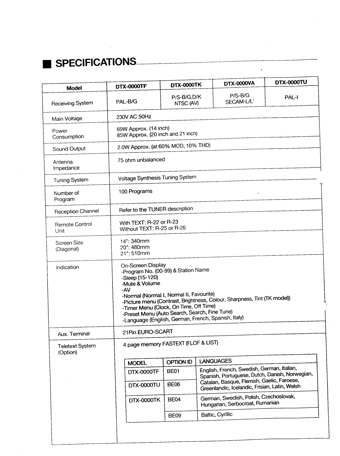

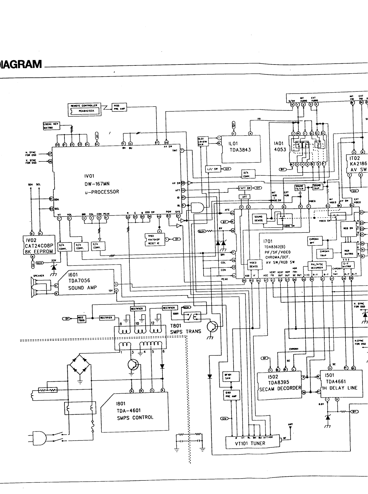
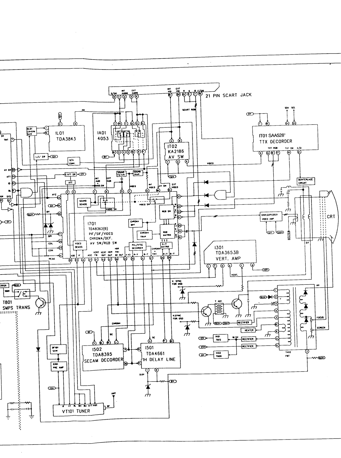
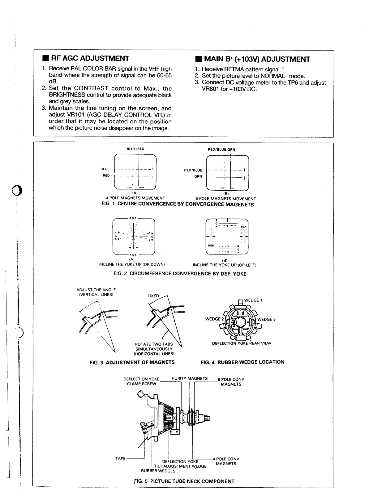
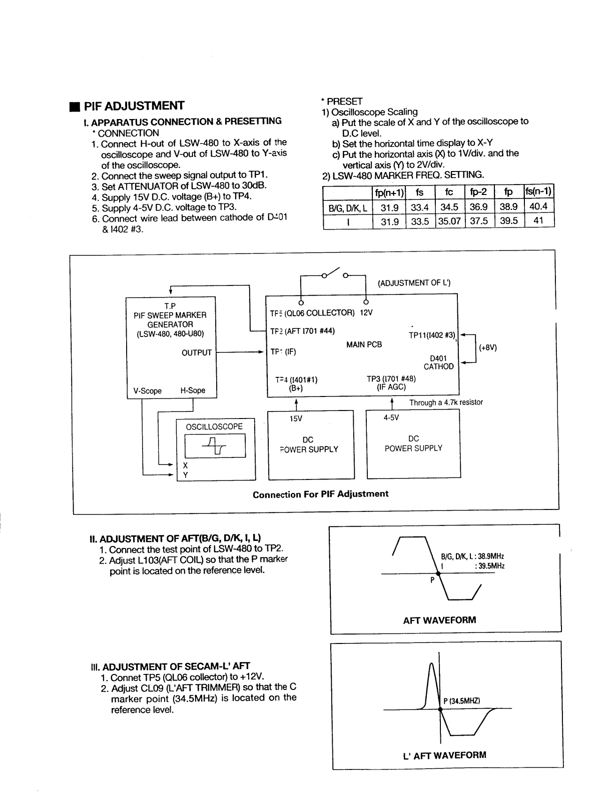
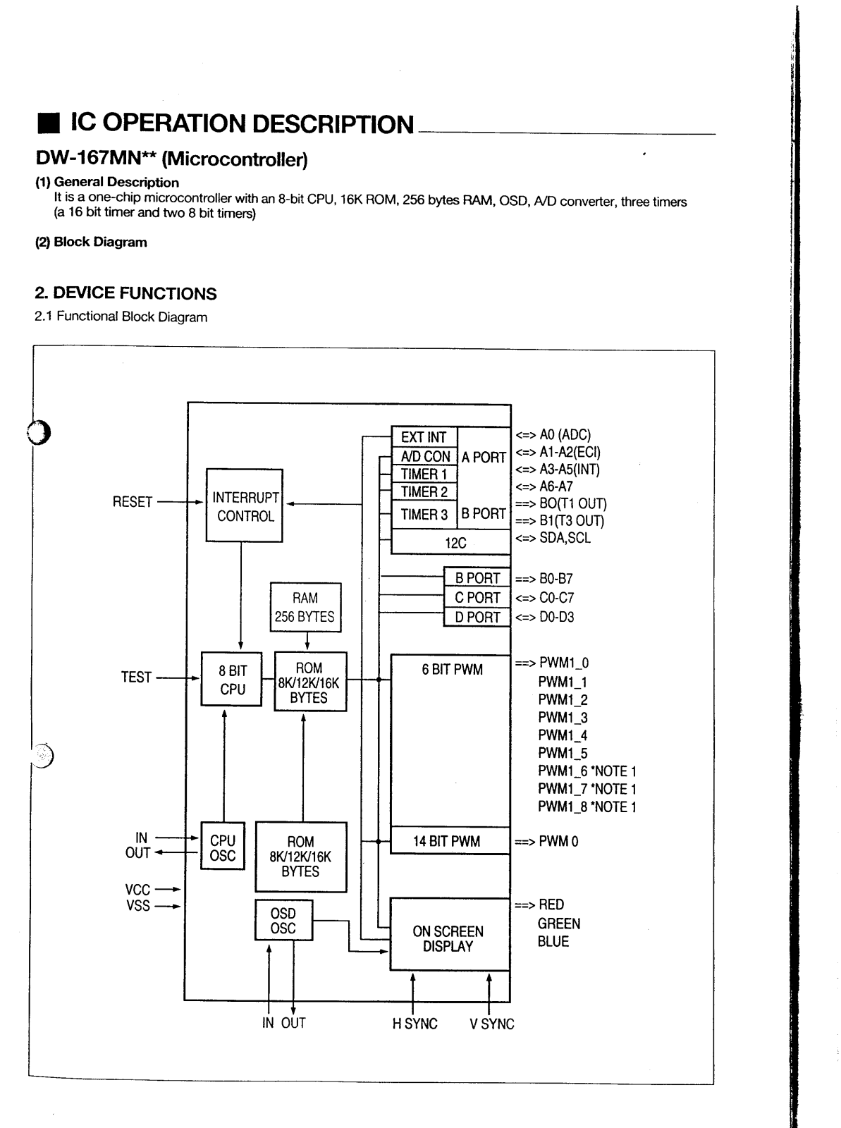
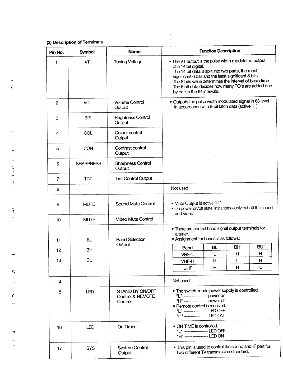
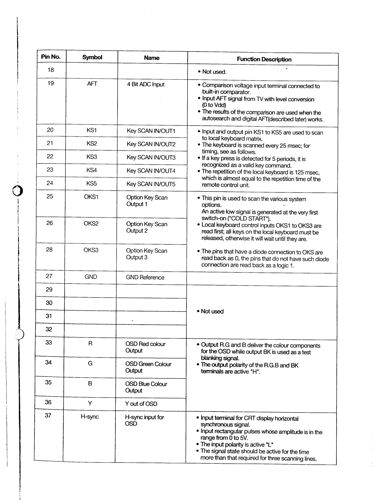
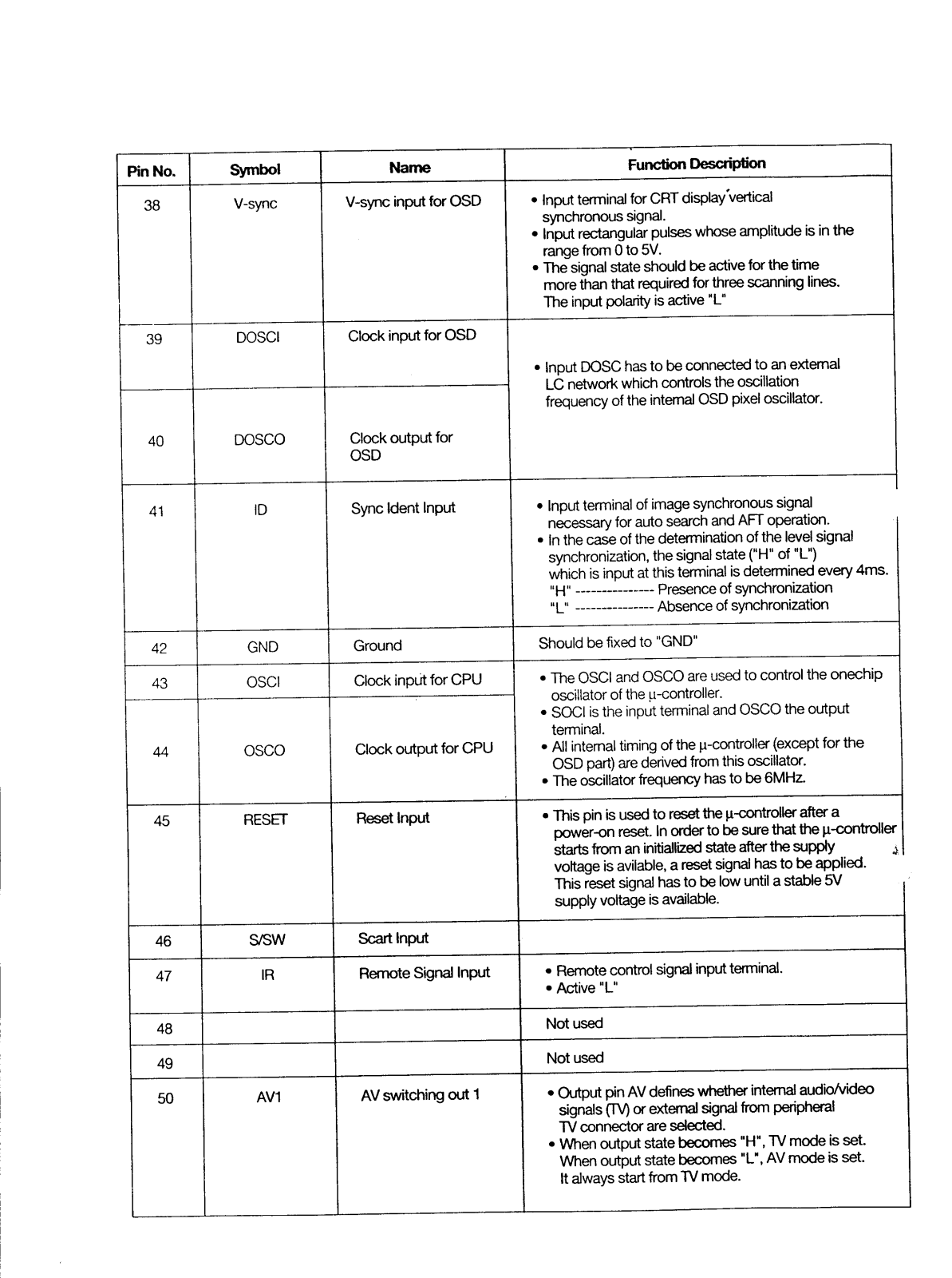
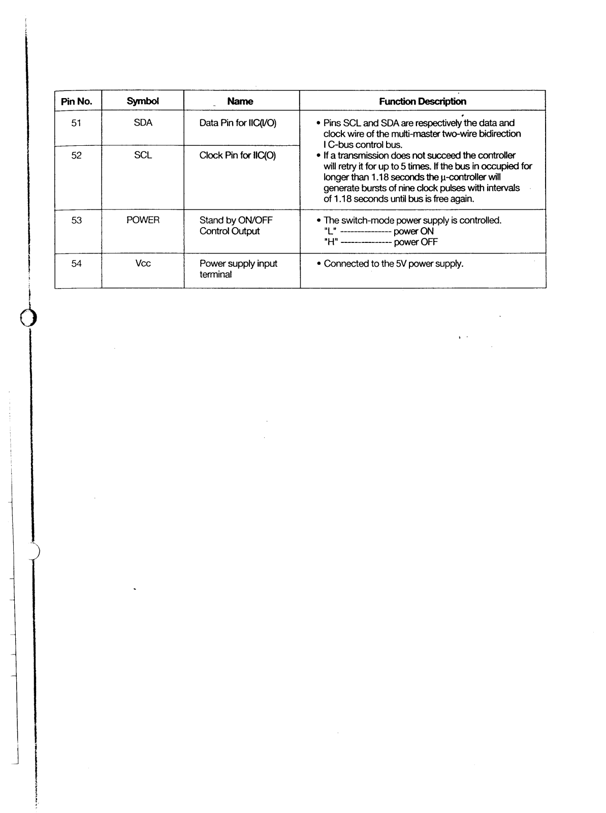
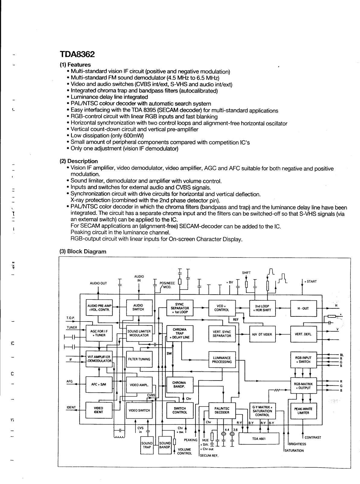
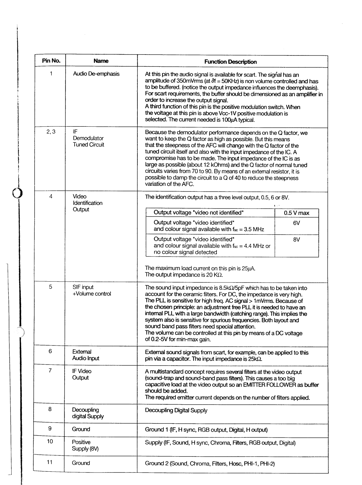
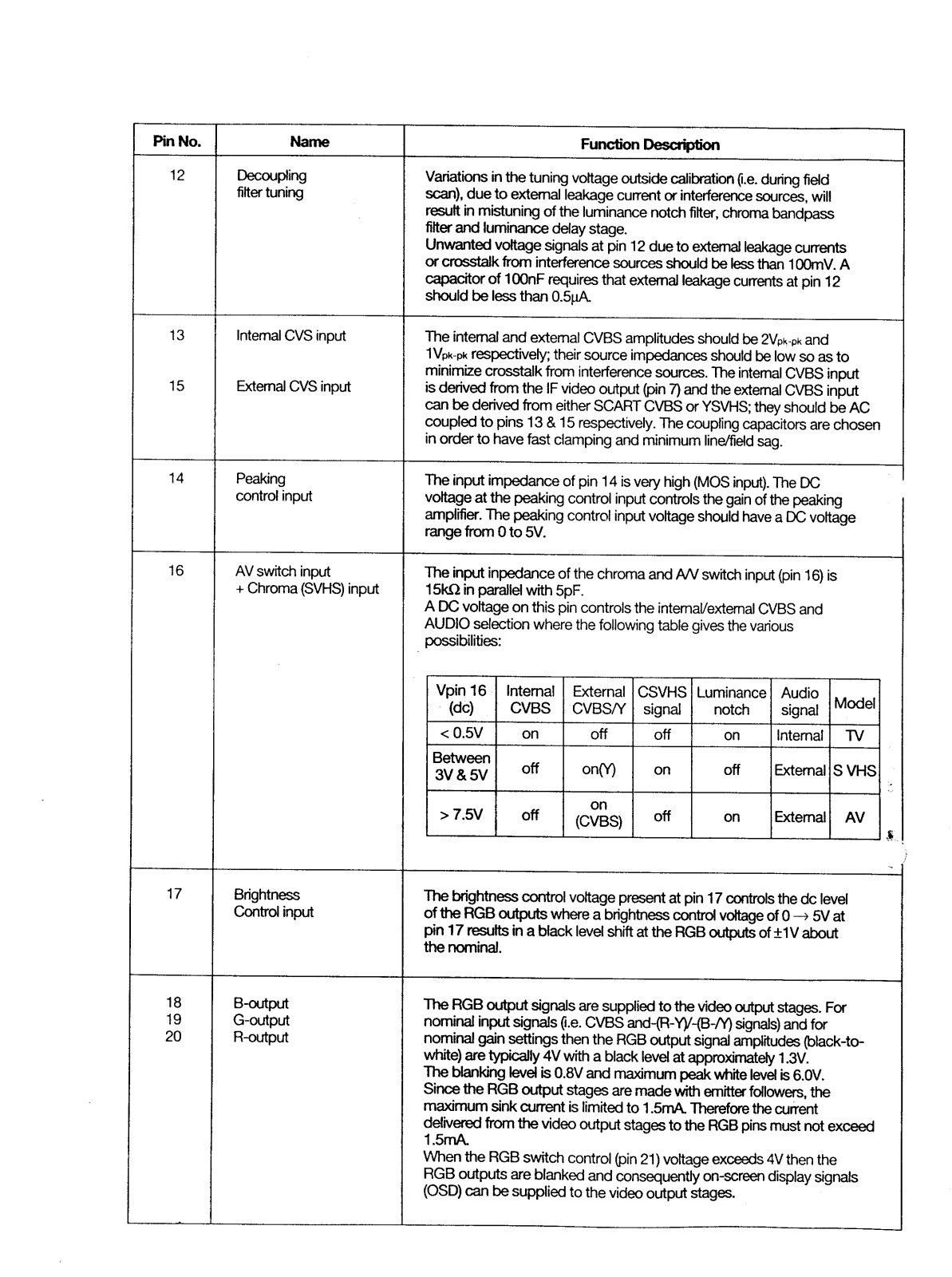
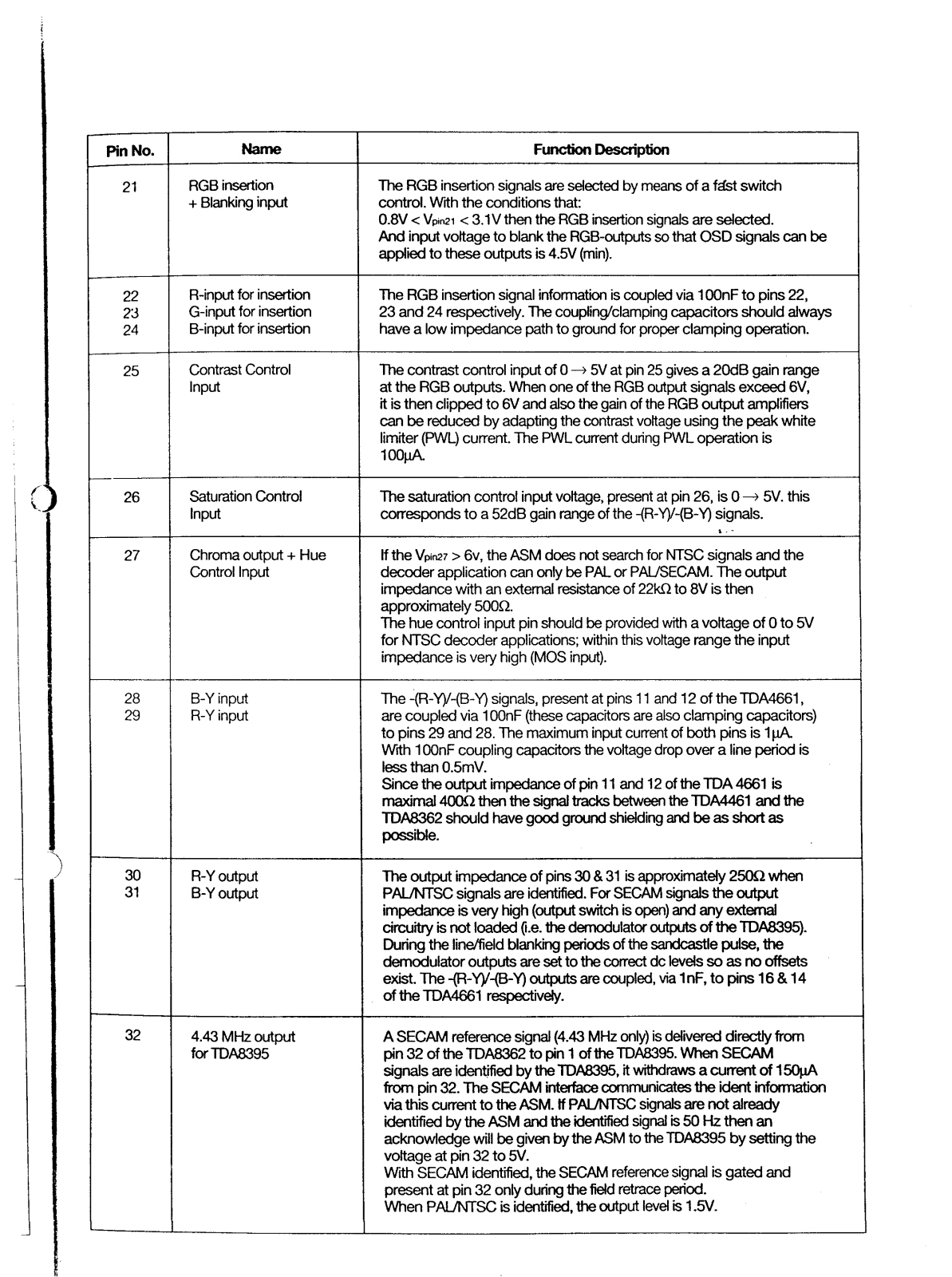
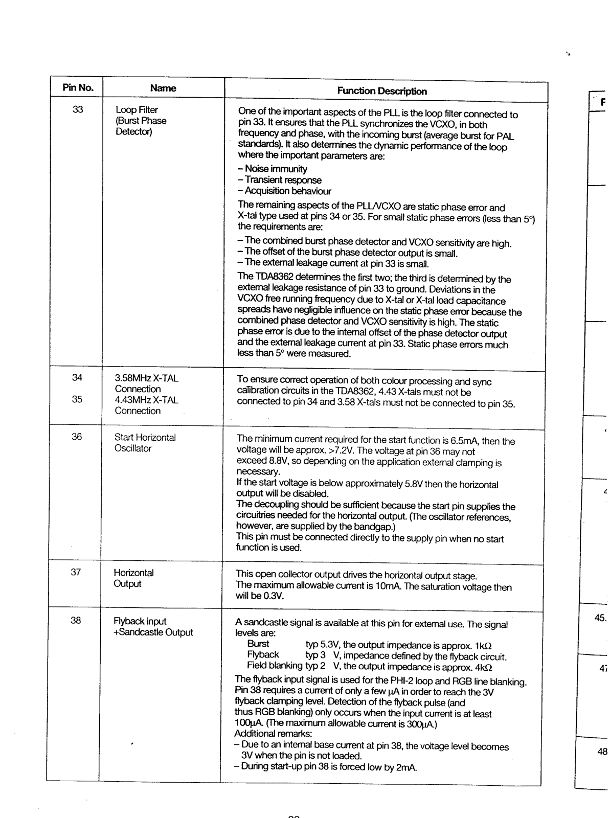
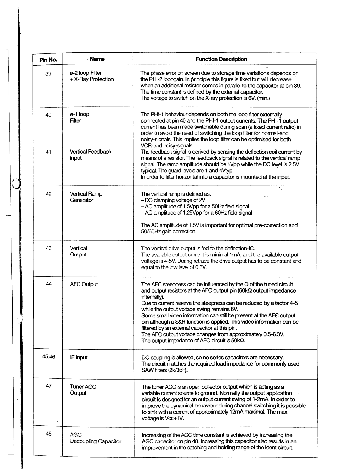
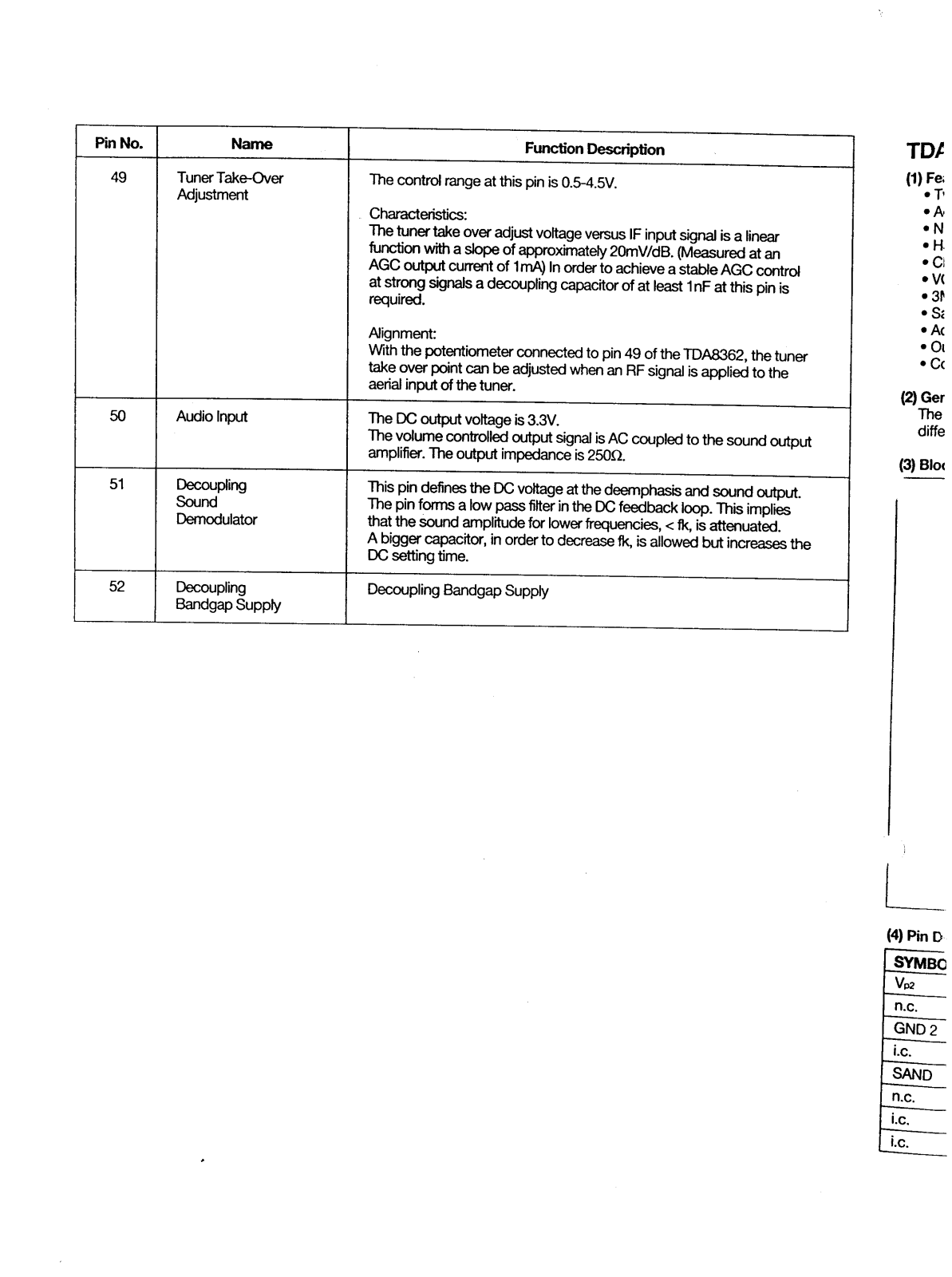
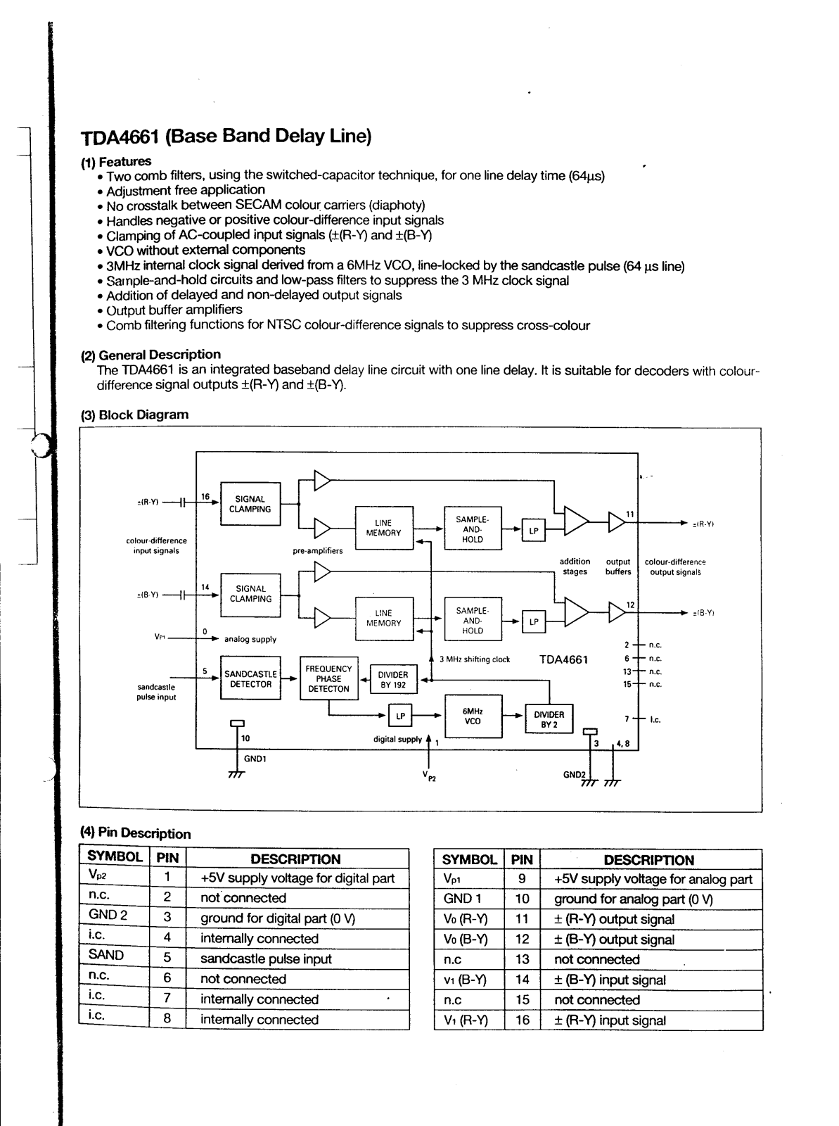
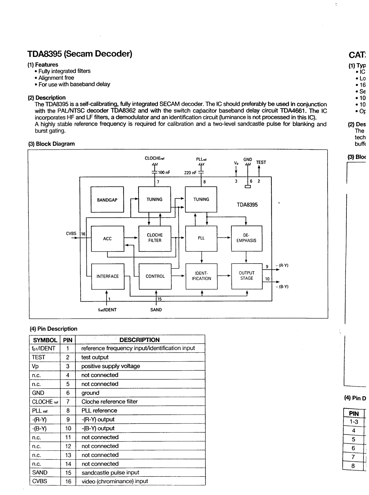
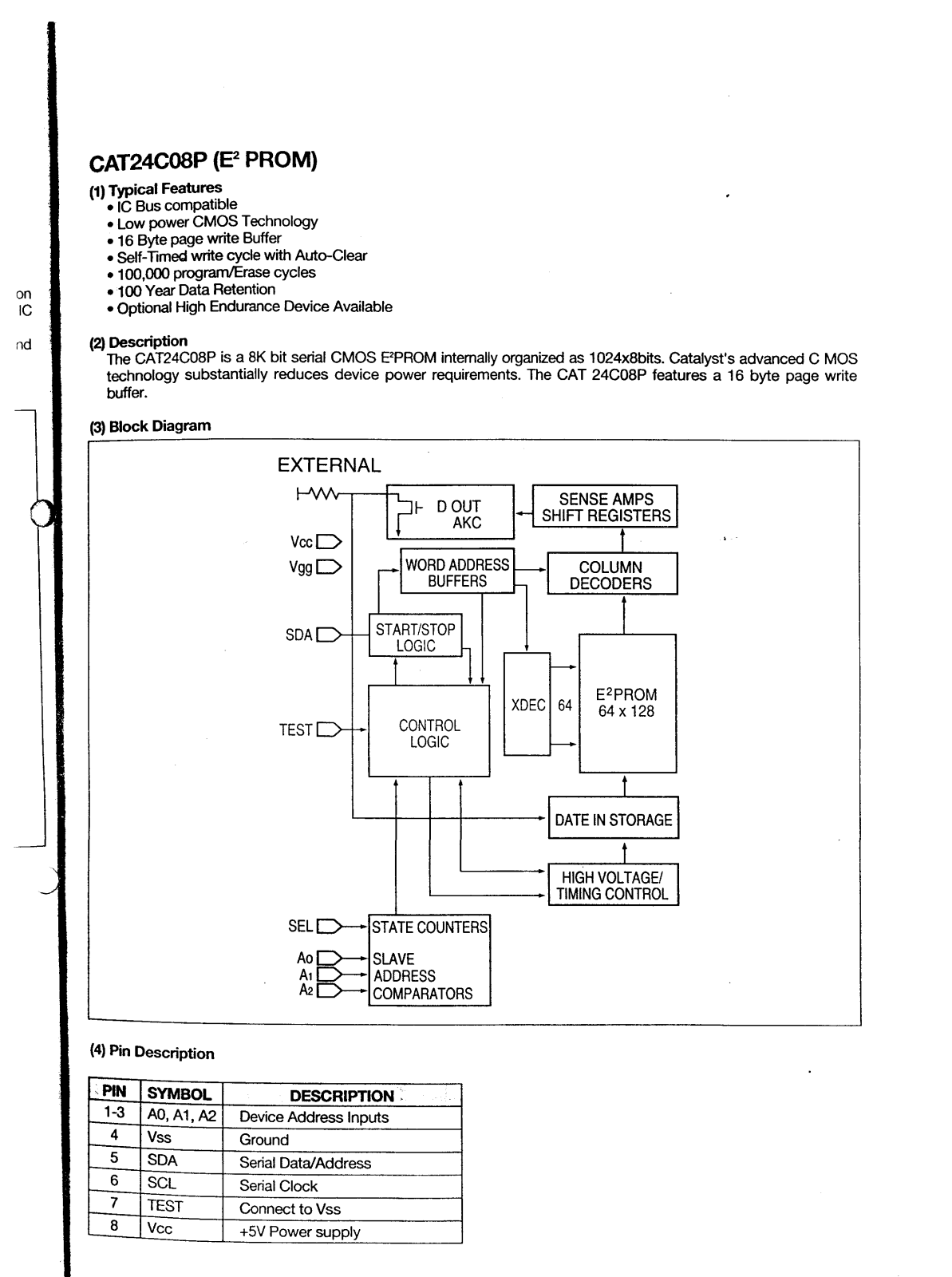
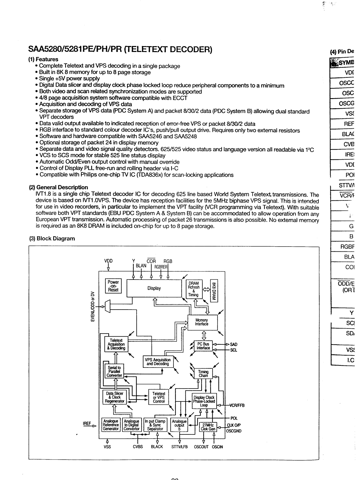
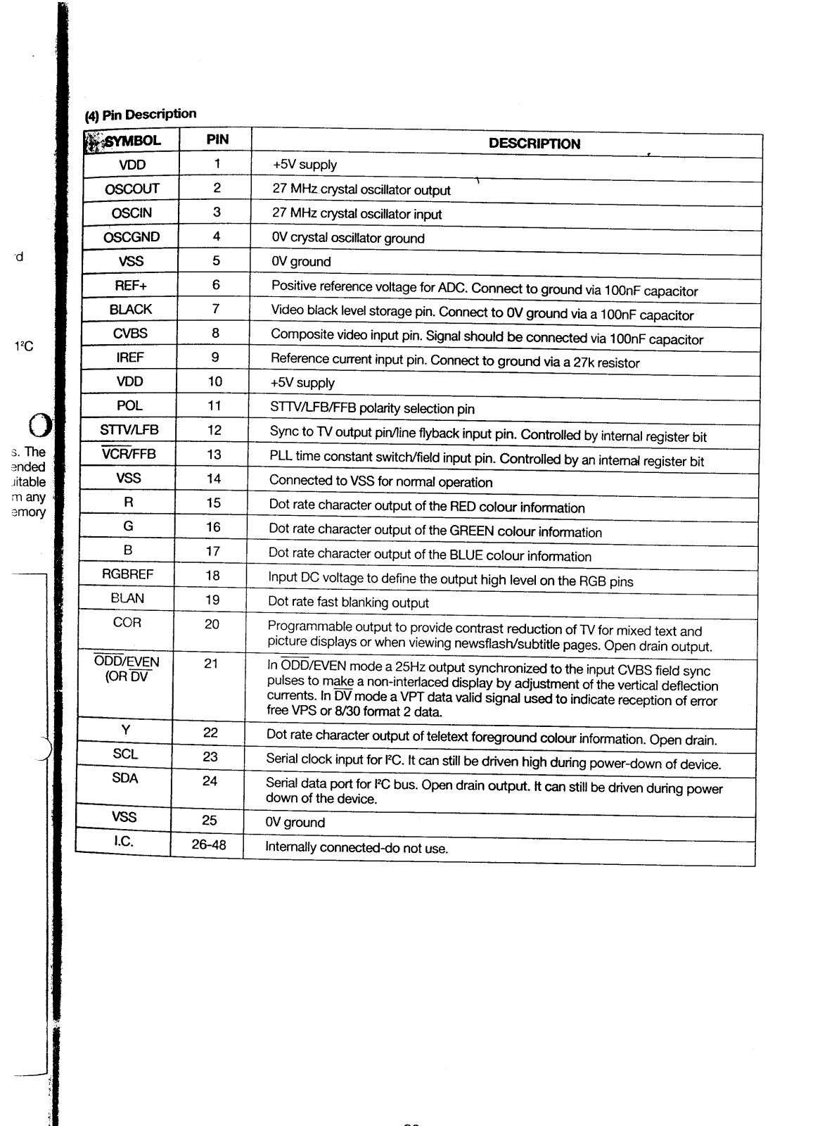
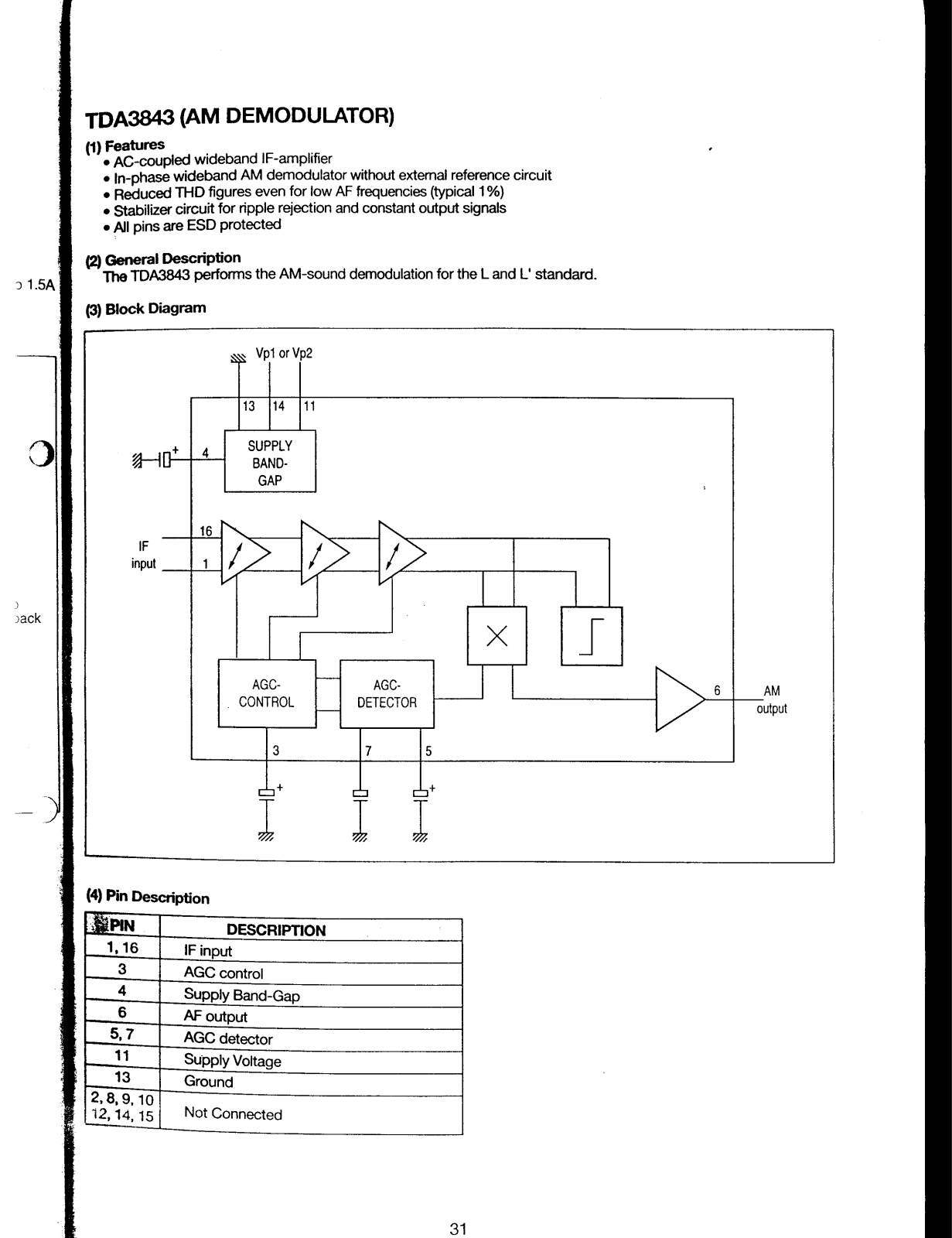
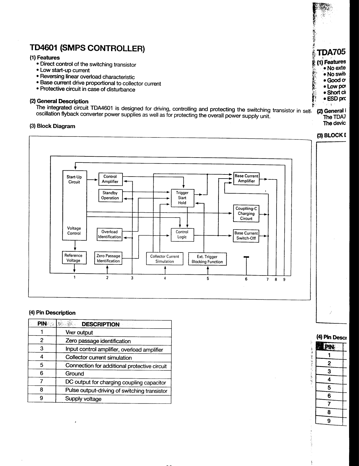


 Loading...