

Daewoo DTQ-25G1TS User Manual
Color Television
INSTRUCTION MANUAL
DTQ 25G1TS
DTQ 29G1TS
P/N : 48586217E208-R0
CAUTION
RISK OF ELECTRIC SHOCK
DO NOT OPEN
CAUTION : T O REDUCE THE RISK OF ELECTRIC SHOCK,
DO NOT REMOVE COVER (OR B A CK)
NO USER-SER VICEABLE PARTS INSIDE.
REFER SER VICING T O QUALIFIED SER VICE PERSONNEL.
The lightning flash with arrowhead symbol, within an equilateral triangle, is
intended to alert the user to the presence of uninsulated “dangerous voltage” within the product’s enclosure that may be of sufficient magnitude to constitute a risk
electric shock.
The exclamation point within an equilateral triangle is intended to alert the user to
the presence of important operating and servicing instructions in the literature
accompanying the appliance.
WARNING
TO PREVENT FIRE OR SHOCK HAZARD, DO NOT EXPOSE THIS APPLIANCE TO RAIN
OR MOISTURE.
CAUTION
CHANGES OR MODIFICATIONS NOT EXPRESSLY APPROVED BY THE MANUFACTURER COULD VOID THE USER’S AUTHORITY TO OPERATE THE EQUIPMENT.
NOTE TO CATV SYSTEM INST ALLER
THIS REMINDER IS PROVIDED TO CALL THE CATV SYSTEM INSTALLER'S ATTENTION TO ARTICLE 820-40 OF THE NEC THAT PROVIDES GUIDELINES FOR PROPER
GROUNDING AND, IN PARTICULAR, SPECIFIES THAT THE CABLE GROUND SHALL
BE CONNECTED TO THE GROUNDING SYSTEM OF THE BUILDING, AS CLOSE TO
THE POINT OF CABLE ENTRY AS PRACTICAL.
CAUTION
To provide power to the TV, insert the AC plug into a standard 120V , 60Hz outlet.
NOTE
If you feel a static discharge when touching the unit, and the unit does not function, simply unplug
the unit from the outlet. When you plug the unit back in, it should work normally.
Do not install power cords near any heating element or cooking appliances.

CONTENTS
Table of Contents
IMPORTANT SAFEGUARDS 3
Chapter 1: Connecting an Antenna/Cable and VCR to Your TV 5
Connecting an Antenna 5
Antennas with two sets of leads 6
Connecting a Cable System 6
Connecting a VCR 8
Connecting Other pieces of Equipment 8
Safety Note 8
Chapter 2 : Overview of Your Equipment 9
Your TV’s Front View 9
Your TV’s Back View 9
Your remote control 10
Installing your remote control batteries 12
Notes 12
Chapter 3 : Operating Your TV 13
Turning your TV ON/OFF 13
Changing channels 13
Changing volume 13
Understanding On-Screen menu 14
Selecting the Input Source 15
Using the direct button on the remote control. 15
Using on-Screen Menu 15
Programming Your TV’s Channel Memory 16
Source Selection 16
Auto Programming Function 16
Adding and Erasing Channels 17
Adjusting the Picture 18
Custom mode 18
Preset mode 19
Adjusting the Sound 20
Selecting stereo/SAP broadcasts 20
About AVC 20
About Loudness 20
Convenient Remote Function 22
Display On-Screen information 22
Muting the Sound 22
Table of Contents
1

2
Table of Contents
Chapter 4 : Using the Advanced Features 23
Changing the Language of the On-Screen Menus 23
Using closed-Captioned Function 24
Captioning 24
Viewing caption 24
Programming Your Favorite Channels 26
Programming your favorite channels 26
Selecting your favorite channels 26
Setting the Timer 27
Setting the Clock 27
Setting the On-Timer 27
Setting the Off-Timer 27
Setting the Sleep Timer 28
Using the Power Restore feature 29
Chapter 5 : Using the Special Features 30
Watching Picture-In-Picture (PIP Function) 30
Display the PIP image 30
Changing the PIP channels 30
To change the PIP position 30
To Display a picture from an external source as a PIP picture 30
To switch the main and PIP picture 31
To freeze the small picture is displayed 31
Changing the PIP image size 31
Using channel label Feature 32
Programming the channel labels 32
Clearing channel labels 33
Watching Auto demo Feature 34
Starting the on-screen demonstration 34
To stop the demonstration 34
Chapter 6 : Troubleshooting 35
WARRANTY 36
important safeguards
SAFETY
3
IMPORTANT SAFEGUARDS
PLEASE READ ALL THESE INSTRUCTIONS REGARDING YOUR TELEVISION EQUIPMENT AND RETAIN FOR FUTURE REFERENCE. FOLLOW ALL WARNINGS AND
INSTRUCTIONS MARKED ON THE TV RECEIVER.
1 Read all of these instructions.
2 Save these instructions for later use.
3 Unplug this television equipment from the
wall outlet before cleaning. Do not use liquid cleaners or aerosol cleaners. Use a
damp cloth for cleaning.
4 Do not use attachments not recommend-
ed by the television equipment manufacturer as they may result in the risk of fire,
electric shock or other personal injury.
5 Do not use this television equipment near
water, for example, near a bathtub, washbowl, kitchen sink, or laundry tub, in a wet
basement, or near a swimming pool, or
the like.
6 Do not place this television equipment on
an unstable cart, stand, or table, The television equipment may fall, causing serious injury to a child or adult, and serious
damage to the equipment. Use only with
a cart or stand recommended by the
manufacturer, or sold with the television
equipment. Wall or shelf mounting should
follow the manufacturer's instructions,
and should use a mounting kit approved
by the manufacturer.
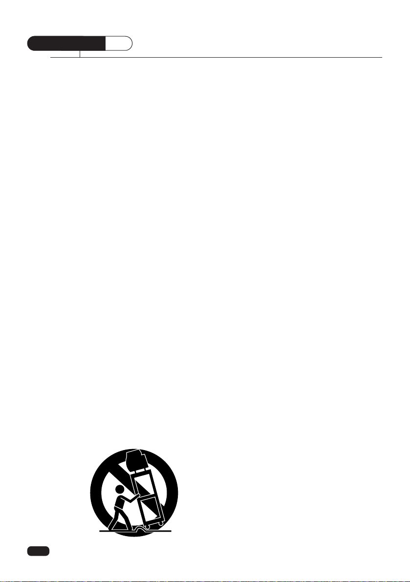
6A An appliance and cart combination should
be moved with care. Quick stops, excessive force, and uneven surface may
cause the appliance and cart combination
to overturn.
7 Slots and openings in the cabinet and the
back or bottom are provided for ventilation and to ensure reliable operation of
the television equipment; and to protect it
from overheating, these opening, must
not be blocked or covered. The opening
should never be blocked by placing the
television equipment on a bed, sofa, rug,
or other similar surface. (This equipment
should never be placed near or over a
radiator or heat register.) This television
equipment should not be placed in a builtin installation such as a bookcase unless
proper ventilation is provided.
8 This television equipment should be oper-
ated only from the type of power source
indicated on the marking label. If you are
not sure of the type of power supplied to
your home, consult your television dealer
or local power company.
9 This television equipment is equipped
with a polarized alternating current line
plug (a plug having one blade wider than
the other). This plug will fit into the power
outlet only one way. This is a safety feature. If you are unable to insert the plug
fully into the outlet, try reversing the plug.
If the plug should still fail to fit, contact
your electrician to replace your obsolete
outlet. Do not defeat the safety purpose
of the polarized plug.
10 Do not allow anything to rest on the pow-
er cord. Do not locate this television
equipment where the cord will be abused
by persons walking on it.
11 Follow all warnings and instructions
marked on the television equipment.
12 For added protection for this television
equipment during a lightning storm, or
when it is left unattended and unused for
long periods of time, unplug it from the
wall outlet and disconnect the antenna or
cable system. This will prevent damage to
the equipment due to lightning and power-line surges.
13 An outside antenna system should not be
located in the vicinity of overhead power
lines or other electric light or power circuits, or where it can fall into such power
lines or circuits. When installing an outside antenna system, extreme care
should be taken to keep from touching
such power lines or circuits as contact
with them might be fatal.
14 Do not overload wall outlets and exten-
sion cords as this can result in fire or
electric shock.
15 Never push objects of any kind into this
television equipment through openings as
they may touch dangerous voltage points
or short-out parts that could result in a fire
or electric shock. Never spill liquid of any
kind on the television equipment.
16 Do not attempt to service this television
equipment yourself as opening or removing covers may expose you to dangerous
voltage or other hazards. Refer all servicing to qualified service personnel.
17 Unplug this television equipment from the
wall outlet and refer servicing to qualified
service personnel under the following
conditions:
(a) When the power-supply cord or plug is
damaged or frayed.
(b) If liquid has been spilled, or objects
have fallen into the television equipment.
(c) If the television equipment has been
exposed to rain or water.
(d) If the television equipment does not
operate normally by following the
operating instructions. Adjust only
those controls that are covered by the
operating instructions as an improper
adjustment of other controls may
result in damage and will often require
extensive work by a qualified technician to restore the TV receiver to its
normal operation.
(e) If the television equipment has been
dropped or the cabinet has been damaged.
(f) When the television equipment exhibits
a distinct change in performance - this
indicates a need for service.
18 When replacement parts are required, be
sure the service technician has used
replacement parts specified by the manufacturer that have the same characteristics as the original part. Unauthorized
substitutions may result in fire, electric
shock or other hazards.
19 Upon completion of any service or repairs
to this television equipment, ask the service technician to perform safety checks
to determine that the television is in a
safe operating condition.
20 If an outside antenna or cable system is
connected to the television receiver, be
sure the antenna or cable system is
grounded so as to provided some protection against voltage surges and built-up
static charges.
Section 810 of the National Electrical
Code, ANSI/NFPA N0.70-1984, provides
information with respect to proper grounding of the mast and supporting structure,
grounding of the lead-in wire to an antenna discharge unit, size of grounding conductors, location of antenna-discharge
unit, connection to grounding electrodes,
and requirements for the grounding electrode.
4
important safeguards
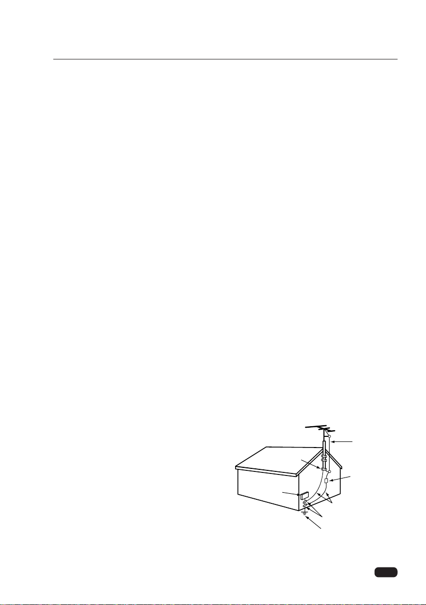
ANTENNA
LEAD IN
WIRE
ANTENNA
DISCHARGE UNIT
(NEC SECTION 810-20)
GROUNDING CONDUCTORS
(NEC SECTION 810-20)
GROUND CLAMPS
POWER SERVICE GROUNDING
ELECTRODE SYSTEM
(NEC ART 250, PART H)
ELECTRIC
SERVICE
EQUIPMENT
NEC-NATIONAL ELECTRICAL CODE
GROUND
CLAMP
EXAMPLE OF ANTENNA GROUNDING
5
CHAPTER
1
Your TV will provide you with the best performance if you connect it to an external antenna or cable system. Follow the directions below to make this connection. Please note that
you will normally only have to make one of the connections shown below, not all of them.
All connections will be made to the antenna terminal on the back of your TV. The antenna
terminal is a silver metal post partially surrounded by two plastic tabs. For help in locating
the antenna terminal, see “Your TV’s Back View” on page 9.
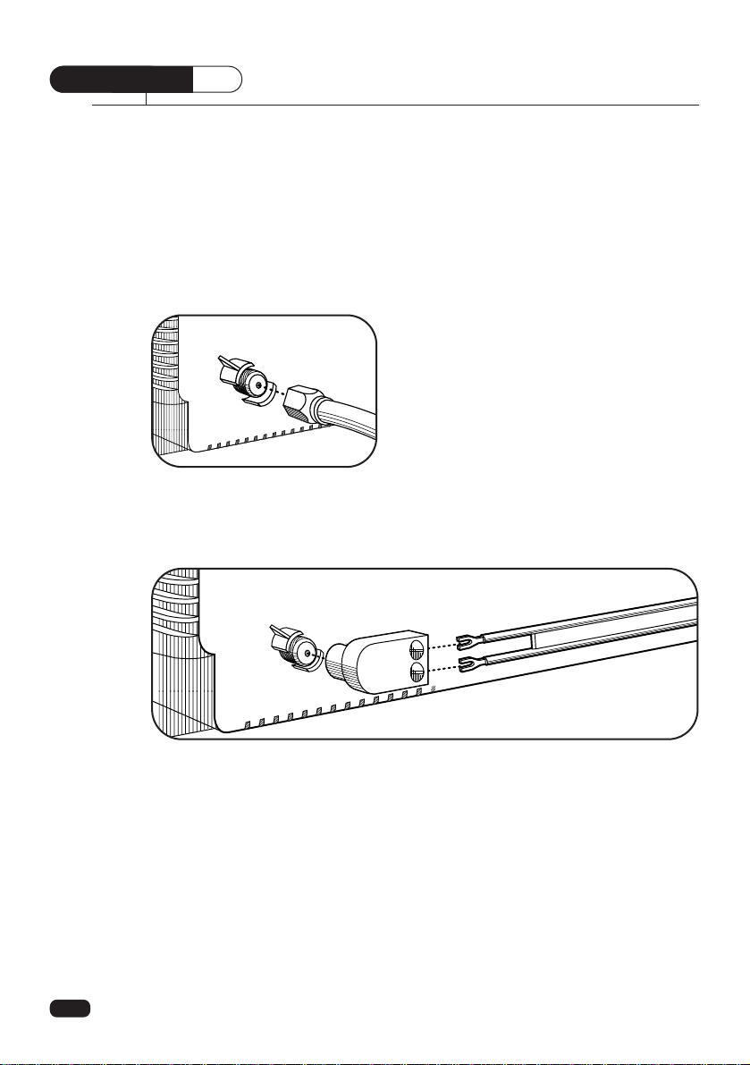
Connecting an Antenna
If your antenna ends in a single coaxial lead,
simply press or screw the cable onto the antenna
terminal on the back of your TV.
If your antenna ends in a pair of 300 ohm twin leads, you must use a 300-ohm/75-ohm
adapter. Place the leads underneath the screws on the adapter, tighten the screws, then press
the adapter onto the antenna terminal on the back of the TV.
Chapter 1 : Connecting an Antenna/Cable and VCR to Your TV
Connecting an Antenna/Cable and VCR to Your TV
6
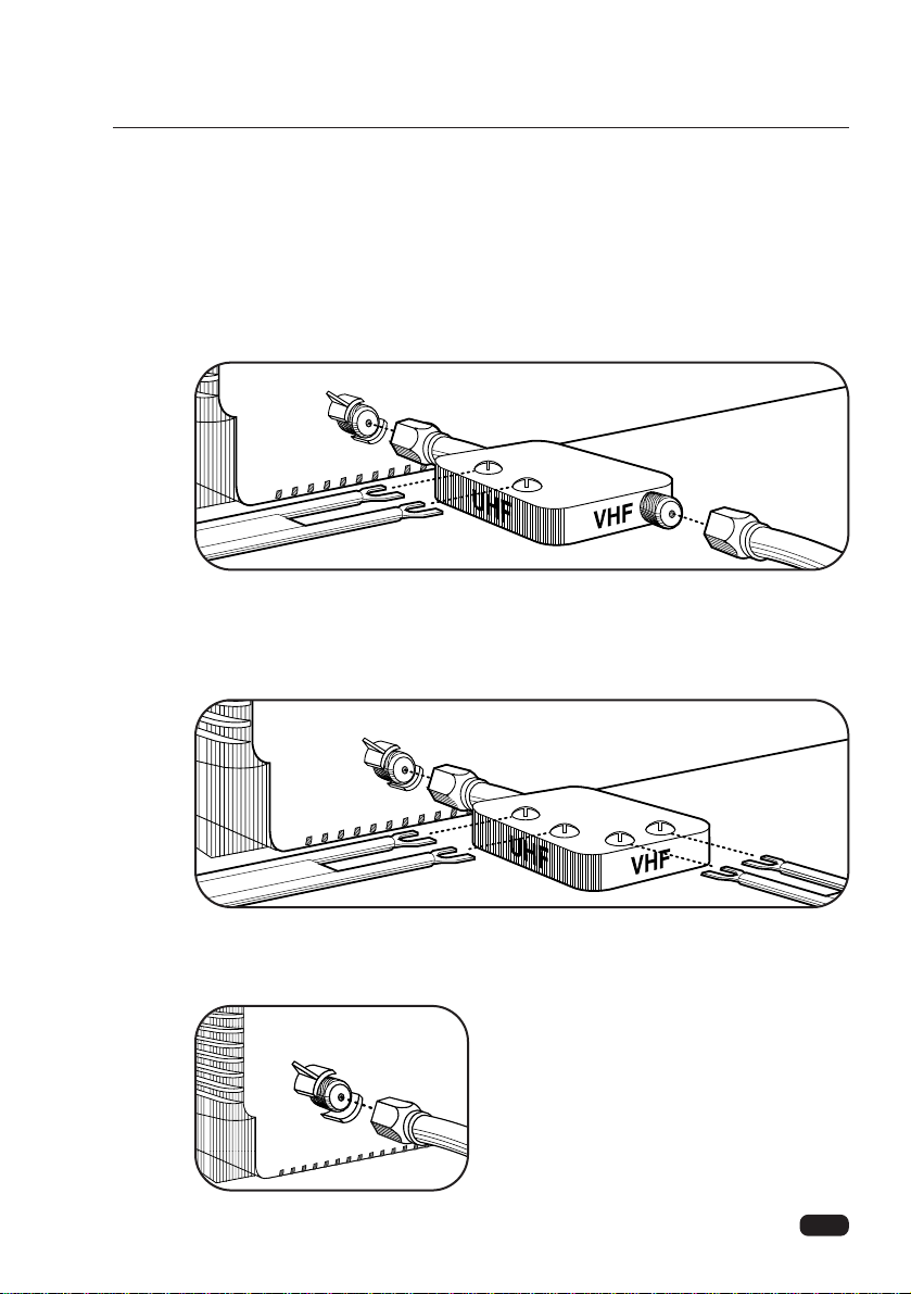
Antennas with two sets of leads
You might have two sets of leads from your antenna system, especially if you have one
antenna for VHF signals and one antenna for UHF signals.
If your antenna system has both a coaxial lead and twin 300-ohm leads, you must
obtain a combiner (available at your local electronics store). Press or screw the coaxial lead
onto the combiner; place the twin leads underneath the screws on the combiner and tighten
the screws. Press the cable from combiner onto the antenna terminal on the back of your
TV.
If your antenna system has two sets of twin 300-ohm leads, you must obtain a combiner
(available at your local electronics store). Place one set of twin leads underneath the screws
on the combiner and tighten the screws. Do the same with the other set of twin leads. Press
the cable from the combiner onto antenna terminal on the back of your TV.
Connecting a Cable System
If your cable set-up is not described below, please contact your cable company for more
information.
If your cable system does not require the use of
a cable box, simply press or screw the incoming
cable onto the antenna terminal on the back your
TV.
Chapter 1 : Connecting an Antenna/Cable and VCR to Your TV
7
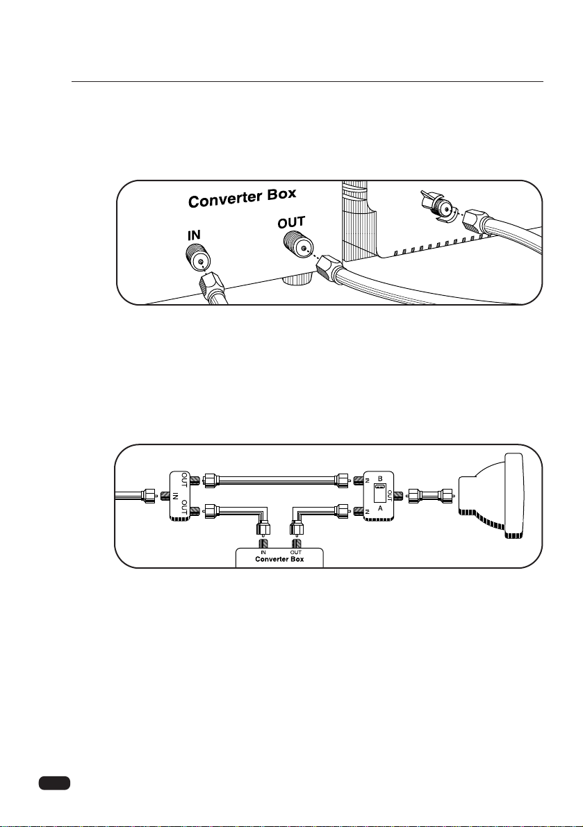
If your cable system requires you to use a converter box for all channels, connect the
incoming cable to the IN terminal on the converter box. Connect another cable between the
OUT terminal on the converter box and the antenna terminal on the TV. You will need to
keep your TV tuned to channel 3 or 4 and change channels using the converter box.
If your cable system only requires you to use a converter box for some channels (i. e.
pay-TV channels), follow these steps: Find the primary incoming coaxial cable. Plug this
cable into a splitter (available at your local electronics store). Connect one coaxial cable
between one OUT terminal on the splitter and the IN terminal on the converter box.
Connect another coaxial cable between the other OUT terminal on the splitter and the B-IN
terminal on an A/B switch (available at your local electronics store.) Connect a third coaxial
cable between the OUT terminal on the converter box and the A-IN terminal on the A/B
switch. Finally, connect a coaxial cable between the OUT terminal on the A/B switch and
the antenna terminal on the back of your TV.
When the A/B switch is in the A position, you need to change channels on the converter
box (and your TV should be tuned to channel 3 or 4); when the A/B switch is in the B position you can change channels on the TV.
Chapter 1 : Connecting an Antenna/Cable and VCR to Your TV
8
Chapter 1 : Connecting an Antenna/Cable and VCR to Your TV
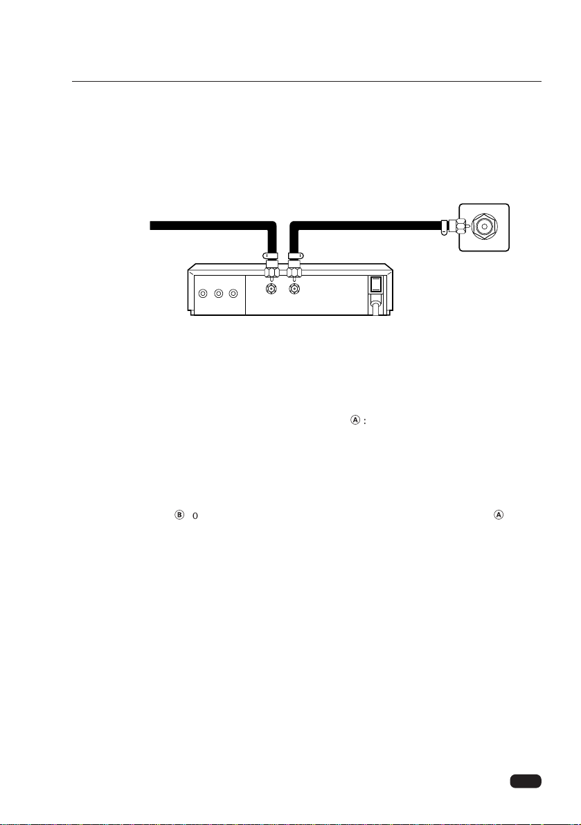
Connecting a VCR
After antenna cable connections are made, you are still required to connect the VCR using a
video/audio connecting cables for (stereo) playback of good quality from the VCR.
Note : On many VCR’s, playing tapes causes the VCR’s TV/VCR switching to disconnect
the antenna signals from the TV. If you cannot select a certain channel, try pressing
the TV/VCR button on the remote control.
Note :
• When connecting a cable TV converter/decoder Æ:
The unscrambled channels will come through the ANT-1 terminal whenever the antenna
input is set to the ANT 1 mode.
The scrambled channels from the decoder box will come through the VCR and the ANT-2
terminal whenever the antenna input is set to the ANT 2 mode. Select channel 3 or 4 on
your TV and VCR to match your converter’output channel.
• The cable ∫connection is necessary only when the cable TV converter/decoder Æis connected.
Connecting Other Pieces of Equipment
You may want to connect a VCR, laser disc player, satellite receiver, or another type of
equipment to your TV. We recommend that you follow the instructions included with the
piece of equipment you wish to connect.
Safety Note
If you plan on being away from your home for an extended period of time, or if a thunderstorm is approaching, you should unplug your television, and you may wish to disconnect
your TV from a rooftop or satellite antenna. You do not need to disconnect your TV from a
cable system.
ANT-1
Antenna
AUDIO
R OUT L
VIDEO
OUT
IN OUT
ANT
VCR
or
Cable
Iead-in
9
Chapter 2 : Overview of your equipment
CHAPTER
2
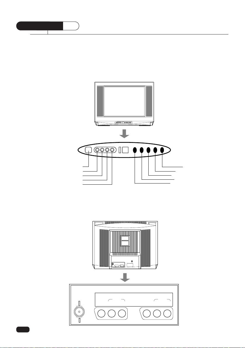
Your TV comes with a remote control. The section below summarizes the buttons, controls,
and terminals that you will use with your TV.
Overview of Your Equipment
Menu
Volume Up
Volume down
Channel Up
Channel down
POWER
Video
L(Mono)
R
Earphone
ANT
T
VIDEO1 IN MONITOR OUT
VIDEO
AUDIO
L(mono) R
VIDEO
AUDIO
L R
Your TV’s Front View
Your TV’s Back View
10
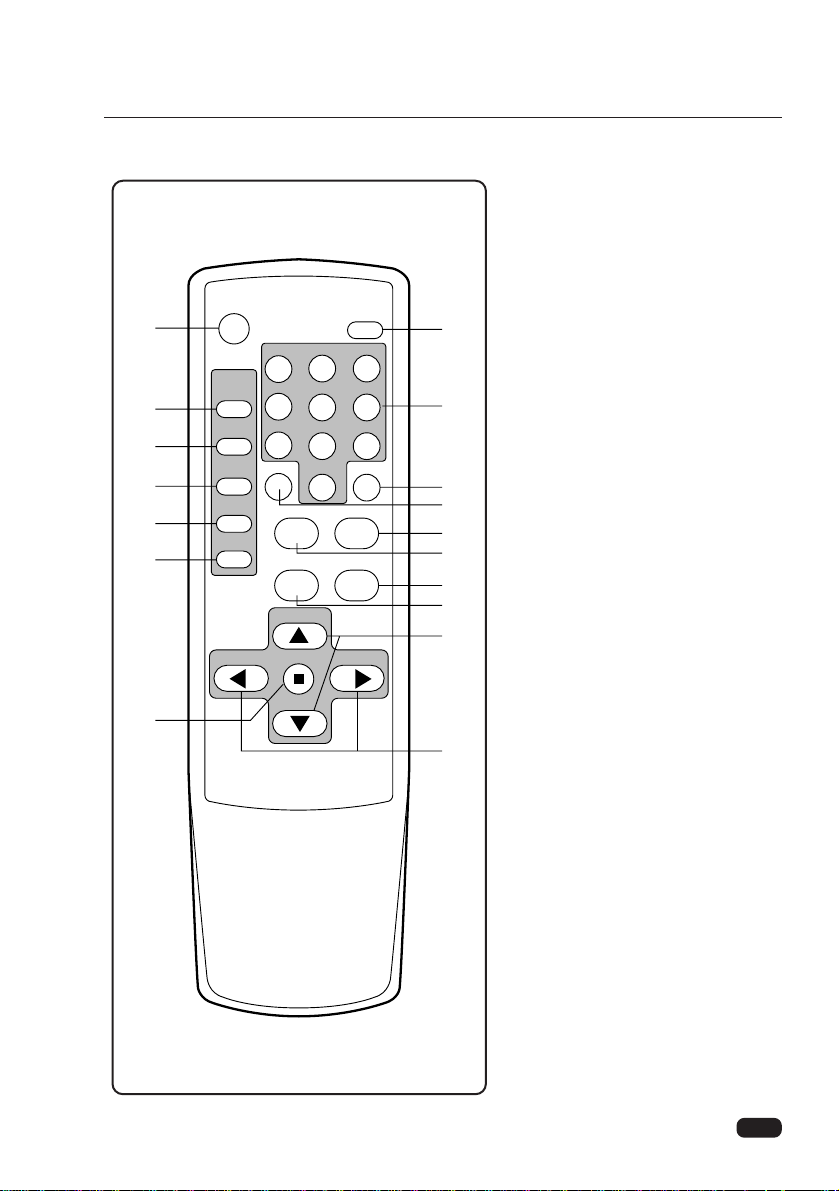
1 POWER
Use this button to turn your TV on
or off.
2 MUTE
Use to turn the TV’s sound on and
off.
3 PIP ON/OFF
Use this button to turn PIP on/off.
4 PIP POSITION
Use this button to move PIP display
position.
5 PIP SOURCE
Use this button to select PIP source.
6 PIP SWAP
Use this button to exchange PIP
source and main source.
7 PIP STILL
Use this button to still PIP source.
8 0-9
Use these buttons to select
channels.
9 SLEEP
Use this button to program the TV
to turn off after a certain time.
10 RECALL
-Use this button to display the
channel number, channel label and
stereo status.
-Use this button repeatedly to select
the main menu or sub menu.
(Changing the channel)
11 TV/VIDEO
Use this button to select main
picture source.
Chapter 2 : Overview of your equipment
Your remote control
POWER
123
456
7809
SLEEP RECALL
MUTE
PIP
ON/OFF
POSITION
SOURCE
SWAP
STILL
TV/VIDEO FAVORITE CH
CAPTION
CH
CH
REMOTE CONTROLLER R-35H13
MENUVOL VOL
MTS
1
3
4
5
6
7
17
2
8
10
9
12
11
14
13
15
16
 Loading...