


Service Manual
Color Television
CN-201A/B
CHASSIS
MODEL:DTQ-14Q1FS, DTQ-14Q2TS
DTQ-14Q3FS, DTQ-14T1AS
DTQ-14T2FS, DTQ-20Q1FS
DTQ-20Q2FS, DTQ-20Q3FS
DTQ-20T1AS, DTQ-20T2AS
DTQ-20T1FS, DTQ-20T2FS
DTQ-20T3FS, DTQ-21T1FS
DTQ-21T2FS, DTQ-21T5FS
DTQ-21T9FS, DTQ-20T1FC
:
NTSC-M SYSTEM
✔
Caution
: In this Manual, some parts can be changed for improving, their
performance without notice in the parts list. So, if you need the
latest parts information,please refer to PPL(Parts Price List) in
Service Information Center (http://svc.dwe.co.kr).
DAEWOO ELECTRONICS CO., LT D .

FEATURES
FS (Frequency Synthesizer) Tuning System
CATV Ready
High Focus Minineck CRT
ELECTRICAL SPECIFICATIONS
POWER INPUT
AC90V - AC250V 50/60Hz
DTQ-20T1FC : 120V 60HZ ONLY
POWER RATING
14” Model 60W
20” MONO Model 70W
20” ST Model 80W
21” ST Model 80W
INTERMEDIATE FREQUENCIES
PICTURE IF CARRIER FREQUENCY 45.75MHz
SOUND IF CARRIER FREQUENCY 41.25MHz
COLOR SUB CARRIER FREQUENCY 42.17MHz
AUDIO OUTPUT RATING MONO(2W) ST(3W+3W)
SPEAKER 3W 16ohm
ANTENNA INPUT IMPEDANCE VHF/UHF 75 ohm UNBALANCED
TUNING RANGES
VHF 2 THRU 13
UHF 14 THRU 69
CATV 1 THRU 125
CONTENTS
Safety Precautions 3
Control View 6
Important Service Notes 8
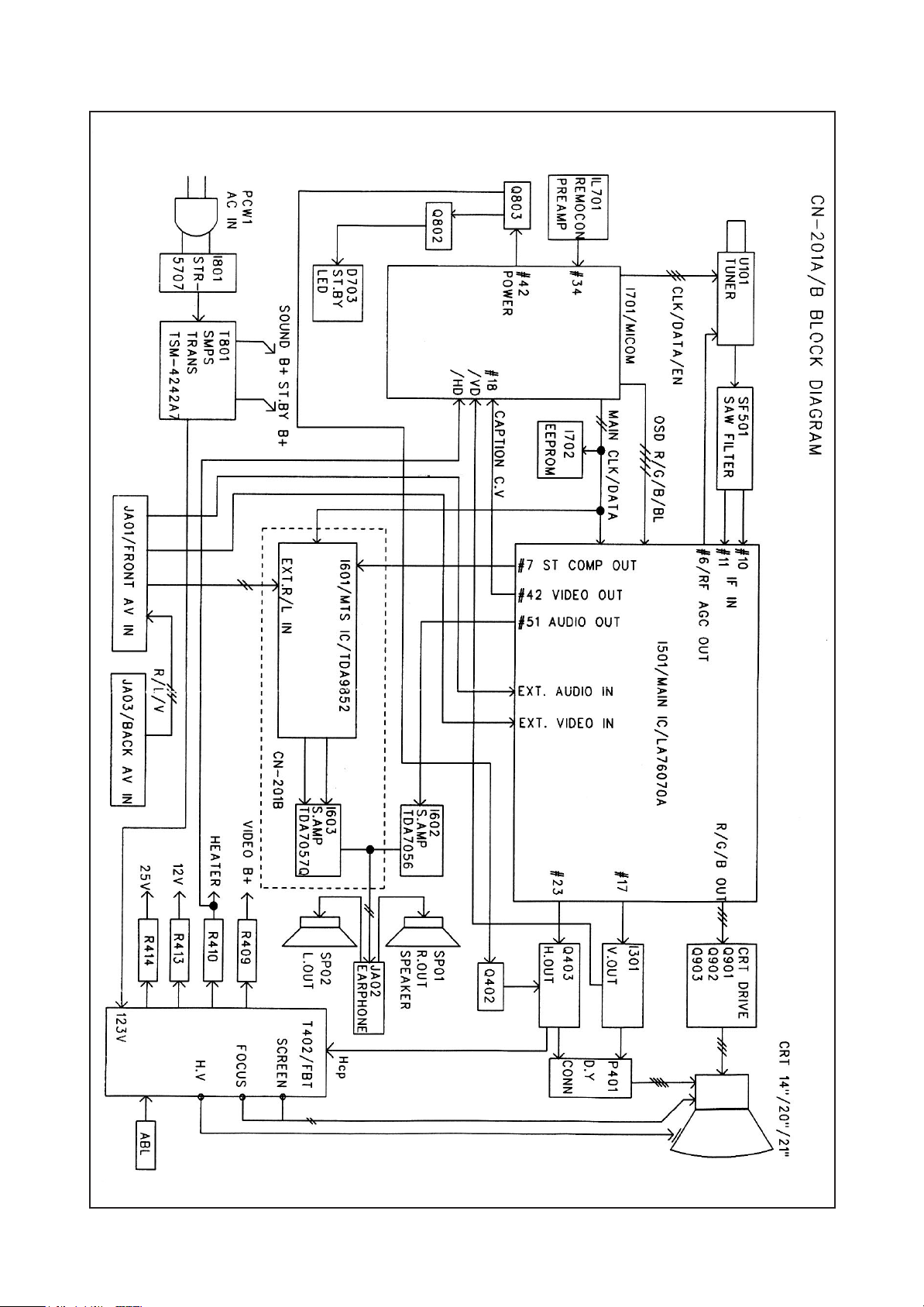
Block Diagram 9
General Adjustments 10
Operation Charaeteristic of Power Block 14
Trouble Shooting Charts 22
Description of Semiconductors 28
Printed Circuit Board Diagram 32
Exploded Views 33
Schematic Diagram with Waveforms 50
Parts List 51
Option List 65
2
PRODUCT SAFETY SERVICING GUIDELINES FOR AUDIO VIDEO PRODUCTS
DO NOT ATTEMPT TO MODIFY THIS PRODUCT IN ANY WAY. NEVER
CAUTION
PERFORM CUSTOMIZED INSTALLATIONS WITHOUT MANUFACTURER S APPROVAL.
UNAUTHORIZED MODIFICATIONS WILL NOT ONLY VOID THE WARRANTY, BUT MAY
LEAD TO YOUR BEING LIABLE FOR ANT RESULTING PROPERTY DAMAGE OR USER
INJURY.
SERVICE WORK SHOULD BE PERFORMED ONLY AFTER YOU ARE THOROUGHLY
FAMILIAR WITH ALL OF THE FOLLOWING SAFETY CHECKS AND SERVICING
GUIDELINES. TO DO OTHERWISE, INCREASES THE RISK OF POTENTIAL HAZARDS AND
INJURY TO THE USER.
WHILE SERVICING, USE AN ISOLATION TRANSFORMER FOR PROTECTION FROM A.C.
LINE SHOCK.
AFTER THE ORIGINAL SERVICE PROBLEM HAS BEEN CORRECTED, A CHECK SHOULD
BE MADE OF THE FOLLOWING:
1. BE SURE THAT ALL COMPONENTS ARE POSITIONED IN SUCH A WAY AS TO AVOID
POSSIBILITY OF ADJACENT COMPONENT SHORTS. THIS IS ESPECIALLY IMPORTANT
ON THOSE MODULES WHICH ARE TRANSPORTED TO AND FROM THE REPAIR SHOP.
2. NEVER RELEASE A REPAIR UNLESS ALL PROTECTIVE DEVICES SUCH AS
INSULATORS, BARRIERS, COVERS, SHIELDS, STRAIN RELIEFS, POWER SUPPLY
CORDS, AND OTHER HARDWARE HAVE BEEN REINSTALLED PER ORIGINAL DESIGN.
BE SURE, THAT THE SAFETY PURPOSE OF THE POLARIZED LINE PLUG HAS NOT
BEEN DEFEATED.
3. SOLDERING MUST BE INSPECTED TO DISCOVER POSSIBLE COLD SOLDER JOINTS,
SOLDER SPLASHES OF SHARP SOLDER POINTS. BE CERTAIN TO REMOVE ALL
LOOSE FOREIGN PARTICLES.
4. CHECK FOR PHYSICAL EVIDENCE OF DAMAGE OR DETERIORATION TO PARTS AND
COMPONENTS, FOR FRAYED LEADS, DAMAGED INSULATION (INCLUDING A.C. CORD),
AND REPLACE IF NECESSARY. FOLLOW ORIGINAL LAYOUT, LEAD LENGTH AND
DRESS.
5. NO LEAD OR COMPONENT SHOULD TOUCH A RECEIVING TUBE OR A RESISTOR
RATED AT 1 WATT OR MORE. LEAD TENSION AROUND PROTRUDING METAL
SURFACES MUST BE AVOIDED.
6. ALL CRITICAL COMPONENTS SUCH AS FUSES, FLAMEPROOF RESISTOR,
CAPACITORS, ETC. MUST BE REPLACED WITH EXACT FACTORY TYPES. DO NOT USE
REPLACEMENT COMPONENTS OTHER THAN THOSE SPECIFIED OR MAKE
UNRECOMMENDED CIRCUIT MODIFICATIONS.
7. AFTER RE-ASSEMBLY OF THE STE ALWAYS PERFORM AN A.C. LEAKAGE TEST ON
ALL EXPOSED METALLIC PARTS OF THE CABINET. (THE CHANNEL SELECTOR KNOB,
ANTENNA TERMINALS, HANDLE AND SCREWS) TO BE SURE THE SET IS SAFE TO
OPERATE WITHOUT DANGER OF ELECTRICAL SHOCK.
ISOLATION TRANSFORMER DURING THIS TEST
HAVING 5000 OHMS PER VOLT OR MORE SENSITIVITY, IN THE FOLLOWING MANNER :
CONNECT A 1500 OHM 10 WATT RESISTOR, PARALLELED BY A .15 MFD. 150V A.C.
TYPE CAPACITOR BETWEEN A KNOWN GOOD EARTH GROUND (WATER POPE,
CONDUIT, ETC.) AND THE EXPOSED METALLIC PARTS, ONE AT A TIME. MEASURE
THE A.C. VOLTAGE ACROSS THE COMBINATION OF 1500 OHM RESISTOR AND .15
MFD CAPACITOR. REVERSE THE A.C. PLUG AND REPEAT A.C. VOLTAGE
MEASUREMENTS FOR EACH EXPOSED METALLIC PART. VOLTAGE MEASURED MUST
NOT EXCEED .75 VOLTS R.M.S THIS CORRESPONDS TO 0.5 MILLIAMP A.C. NAY VALUE
EXCEEDING THIS LIMIT CONSTITUTES A POTENTIAL SHOCK HAZARD AND MUST BE
CORRECTED IMMEDIATELY.
SUBJECT : GRAPHIC SYMBOLS
:
SAFETY CHECKS
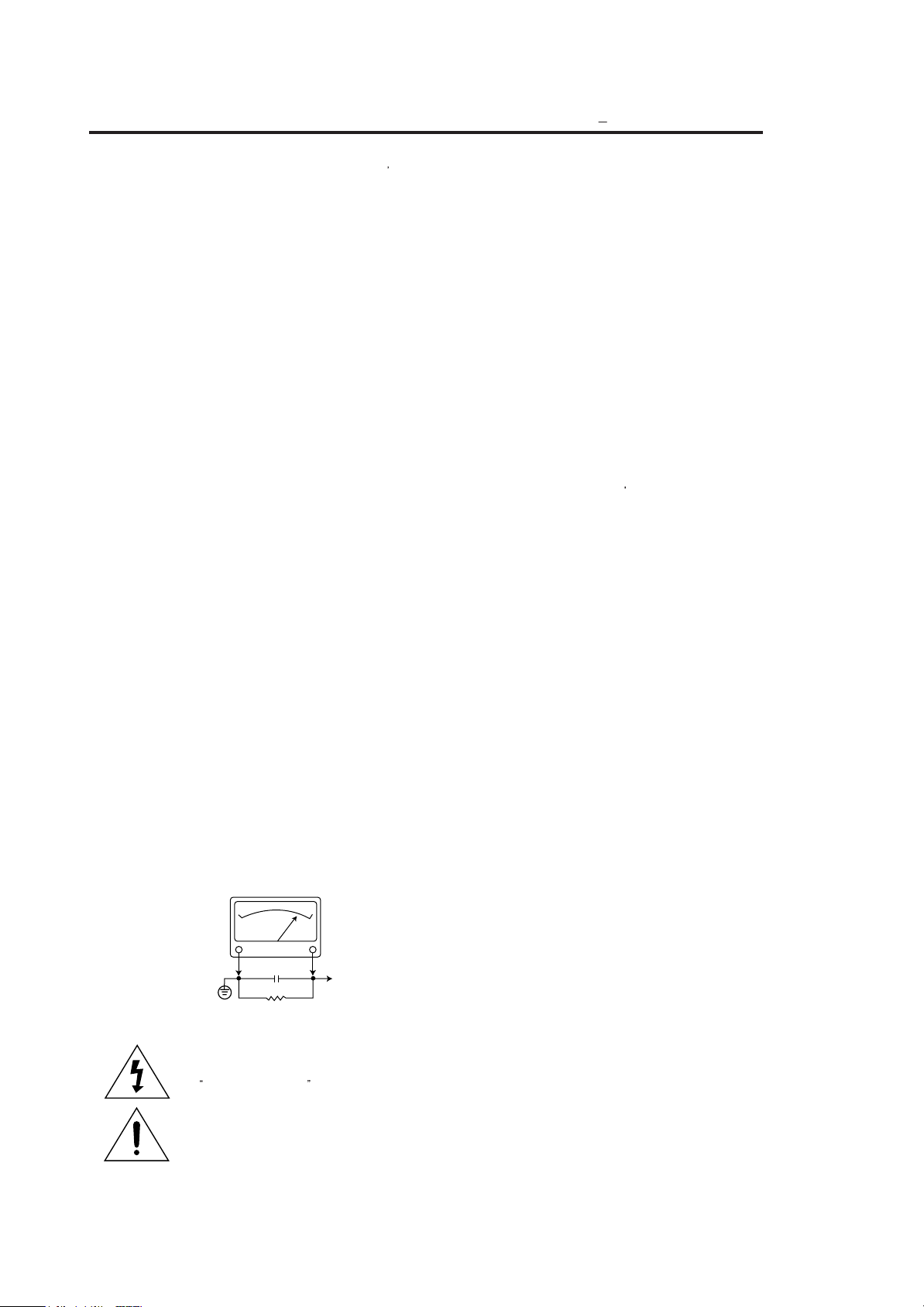
SUBJECT:FIRE & SHOCK HAZARD
A.C. VOLTMETER
A.C. VOLTMETER
GOOD EARTH GROUND
SUCH AS THE WATER
PIPE, CONDUIT, ETC.
THE LIGHTNING FLASH WITH ARROWHEAD SYMBOL, WITHIN
AN EQUILATERAL TRIANGLE, IS INTENDED TO ALERT THE
SERVICE PERSONNEL TO THE PRESENCE OF UNINSULATED
DANGEROUS VOLTAGE THAT MAY BE OF SUFFICIENT
MAGNITUDE TO CONSTITUTE A RISK OF ELECTRIC SHOCK.
THE EXCLAMATION POINT WITHIN AN EQUILATERAL
TRIANGLE IS INTENDED TO ALERT THE SERVICE
PERSONNEL TO THE PRESENCE OF IMPORTANT SAFETY
INFORMATION ON SERVICE LITERATURE.
0.15µF
1500 OHM
10WATT
DO NOT USE A LINE
USE AN A.C. VOLTMETER,
PLACE THIS PROBE
ON EACH EXPOSED
METAL PART
SUBJECT : X-RADIATION
1. BE SURE PROCEDURES AND INSTRUCTIONS TO ALL SERVICE PERSONNEL COVER
2. ONLY FACTORY SPECIFIED C.R.T ANODE CONNECTORS MUST BE USED.
3. IT IS ESSENTIAL THAT SERVICE PERSONNEL HAVE AVAILABLE AN ACCURATE AND
4. WHEN THE HIGH VOLTAGE CIRCUITRY IS OPERATING PROPERLY THERE IS NO
5. WHEN TROUBLESHOOTING AND MAKING TEST MEASUREMENTS IN A PRODUCT WITH
6. REFER TO HV, B + AND SHUTDOWN ADJUSTMENT PROCEDURES DESCRIBED IN THE
SUBJECT : IMPLOSION
1. ALL DIRECT VIEWED PICTURE TUBES ARE EQUIPPED WITH AN INTEGRAL IMPLOSION
2. USE ONLY RECOMMENDED FACTORY REPLACEMENT TUBES.
SUBJECT : TIPS ON PROPER INSTALLATION
1. NEVER INSTALL ANY PRODUCT IN A CLOSED-IN RECESS, CUBBYHOLE OR CLOSELY
2. AVOID CONDITIONS OF HIGH HUMIDITY SUCH AS: OUTDOOR PATIO INSTALLATIONS
3. AVOID PLACEMENT WHERE DRAPERIES MAY OBSTRUCT REAR VENTING. THE
4. WALL AND SHELF MOUNTED INSTALLATIONS USING A COMMERCIAL MOUNTING KIT,
5. CAUTION CUSTOMERS AGAINST THE MOUNTING OF A PRODUCT ON SLOPING SHELF
6. A PRODUCT ON A ROLL-ABOUT CART SHOULD BE STABLE ON ITS MOUNTING TO THE
7. CAUTION CUSTOMERS AGAINST THE USE OF A CART OR STAND WHICH HAS NOT
8. CAUTION CUSTOMERS AGAINST THE USE OF EXTENSION CORDS, EXPLAIN THAT A
950ART94
1009
THE SUBJECT OF X-RADIATION. THE ONLY POTENTIAL SOURCE OF X-RAYS IN
CURRENT T.V. RECEIVERS IS THE PICTURE TUBE. HOWEVER, THIS TUBE DOES NOT
EMIT X-RAYS WHEN THE HIGH VOLTAGE IS AT THE FACTORY SPECIFIED LEVEL. THE
PROPER VALUE IS GIVEN IN THE APPLICABLE SCHEMATIC. OPERATION AT HIGHER
VOLTAGES MAY CAUSE A FAILURE OF THE PICTURE TUBE OR HIGH VOLTAGE
SUPPLY AND, UNDER CERTAIN CIRCUMSTANCES, AMY PRODUCE RADIATION IN
EXCESS OF DESIRABLE LEVELS.
DEGAUSSING SHIELDS ALSO SERVE AS X-RAY SHIELD IN COLOR SETS. ALWAYS REINSTALL THEM.
RELIABLE HIGH VOLTAGE METER. THE CALIBRATION OF THE METER SHOULD BE
CHECKED PERIODICALLY AGAINST A REFERENCE STANDARD. SUCH AS THE ONE
AVAILABLE AT YOUR DISTRIBUTOR.
POSSIBILITY OF AN X-RADIATION PROBLEM. EVERY TIME A COLOR CHASSIS IS
SERVICED, THE BRIGHTNESS SHOULD BE RUN UP AND DOWN WHILE MONITORING
THE HIGH VOLTAGE WITH A METER TO BE CERTAIN THAT THE HIGH VOLTAGE DOES
NOT EXCEED THE SPECIFIED VALUE AND THAT IT IS REGULATING CORRECTLY. WE
SUGGEST THAT YOU AND YOUR SERVICE ORGANIZATION REVIEW TEST
PROCEDURES SO THAT VOLTAGE REGULATION IS ALWAYS CHECKED AS A
STANDARD SERVICING PROCEDURE, AND THAT THE HIGH VOLTAGE READING BE
RECORDED ON EACH CUSTOMER
A PROBLEM OF EXCESSIVE HIGH VOLTAGE, AVOID BEING UNNECESSARILY CLOSE
TO THE PICTURE TUBE AND THE HIGH VOLTAGE SUPPLY. DO NOT OPERATE THE
PRODUCT LONGER THAN IS NECESSARY TO LOCATE THE CAUSE OF EXCESSIVE
VOLTAGE.
APPROPRIATE SCHEMATIC AND DIAGRAMS (WHERE USED).
PROTECTION SYSTEM. BUT CARE SHOULD BE TAKEN TO AVOID DAMAGE DURING
INSTALLATION. AVOID SCRATCHING THE TUBE. OF SCRATCHED REPLACE IT.
FITTING SHELF SPACE, OVER OR CLOSE TO HEAT DUCT, OR IN THE PATH OF
HEATED AIR FLOW.
WHERE DEW IS A FACTOR, NEAR STEAM RADIATORS WHERE STEAM LEAKAGE IS A
FACTOR, ETC.
CUSTOMER SHOULD ALSO AVOID THE USE OF DECORATIVE SCARVES OR OTHER
COVERINGS WHICH MIGHT OBSTRUCT VENTILATION.
MUST FOLLOW THE FACTORY APPROVED MOUNTING INSTRUCTIONS. A PRODUCT
MOUNTED TO A SHELF OR PLATFORM MUST RETAIN ITS ORIGINAL FEET (OR THE
EQUIVALENT THICKNESS IN SPACERS)TO PROVIDE ADEQUATE AIR FLOW ACROSS
THE BOTTOM, BOLTS OR SCREWS USED FOR FASTENERS MUST NOT TOUCH ANY
PARTS OR WIRING. PERFORM LEAKAGE TEST ON CUSTOMIZED INSTALLATIONS.
OR A TILTED POSITION, UNLESS THE PRODUCT IS PROPERLY SECURED.
CART. CAUTION THE CUSTOMER ON THE HAZARDS OF TRYING TO ROLL A CART
WITH SMALL CASTERS ACROSS THRESHOLDS OR DEEP PILE CARPETS.
BEEN LISTED BY UNDERWRITERS LABORATORIES. INC. FOR USE WITH THEIR
SPECIFIC MODEL OF TELEVISION RECEIVER OR GENERICALLY APPROVED FOR USE
WITH T.V.S OF THE SAME OR LARGER SCREEN SIZE.
FOREST OF EXTENSIONS SPROUTING FROM A SINGLE OUTLET CAN LEAD TO
DISASTROUS CONSEQUENCES TO HOME AND FAMILY.
S INVOICE.
3
Product safety servicing guidelines for color
television receivers
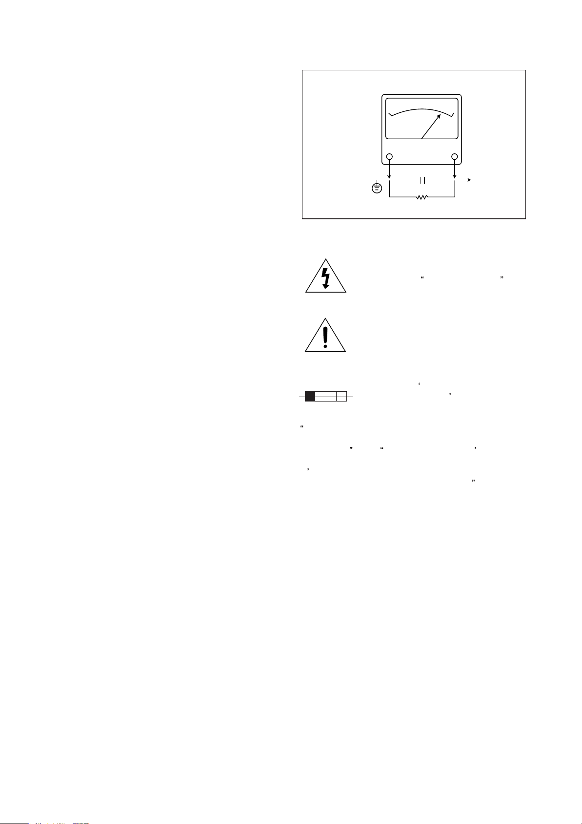
A.C. VOLTMETER
CAUTION :
way. Unauthorized modifications will not only void the
warranty, but may lead to your being liable for any
resulting property damage or user injury.
Service work should be performed only after you are
thoroughly familiar with all of the following safety checks
and servicing guidelines. To do otherwise, increases the
risk of potential hazards and injury to the user.
Do not attempt to modify this product in any
SAFETY CHECKS
After the original service problem has been corrected, a
check should be made of the following:
SUBJECT : FIRE & SHOCK HAZARD
1. Be sure that all components are positioned in such a
way as to avoid possibility of adjacent component
shorts. This is especially important on those chassis
which are transported to and from the repair shop.
2. Never release a repair unless all protective devices
such as insulators, barriers, covers, shields, strain
reliefs, and other hardware have been reinstalled per
original design.
3. Soldering must be inspected to discover possible cold
solder joints, frayed leads, damaged insulation
(including A.C. cord), solder splashes or sharp solder
points. Be certain to remove all loose foreign particals.
4. Check for physical evidence of damage or deterioration
to parts and components, and replace if necessary
follow original layout, lead length and dress.
5. No leads or components should touch a receiving tube
or a resistor rated at 1 watt or more. Lead tension
around protruding metal surfaces must be avoided.
6. All critical components such as fuses, flameproof
resistors, capacitors, etc. must be replaced with exact
factory types. Do not use replacement components
other than those specified or make unrecommended
circuit modifications.
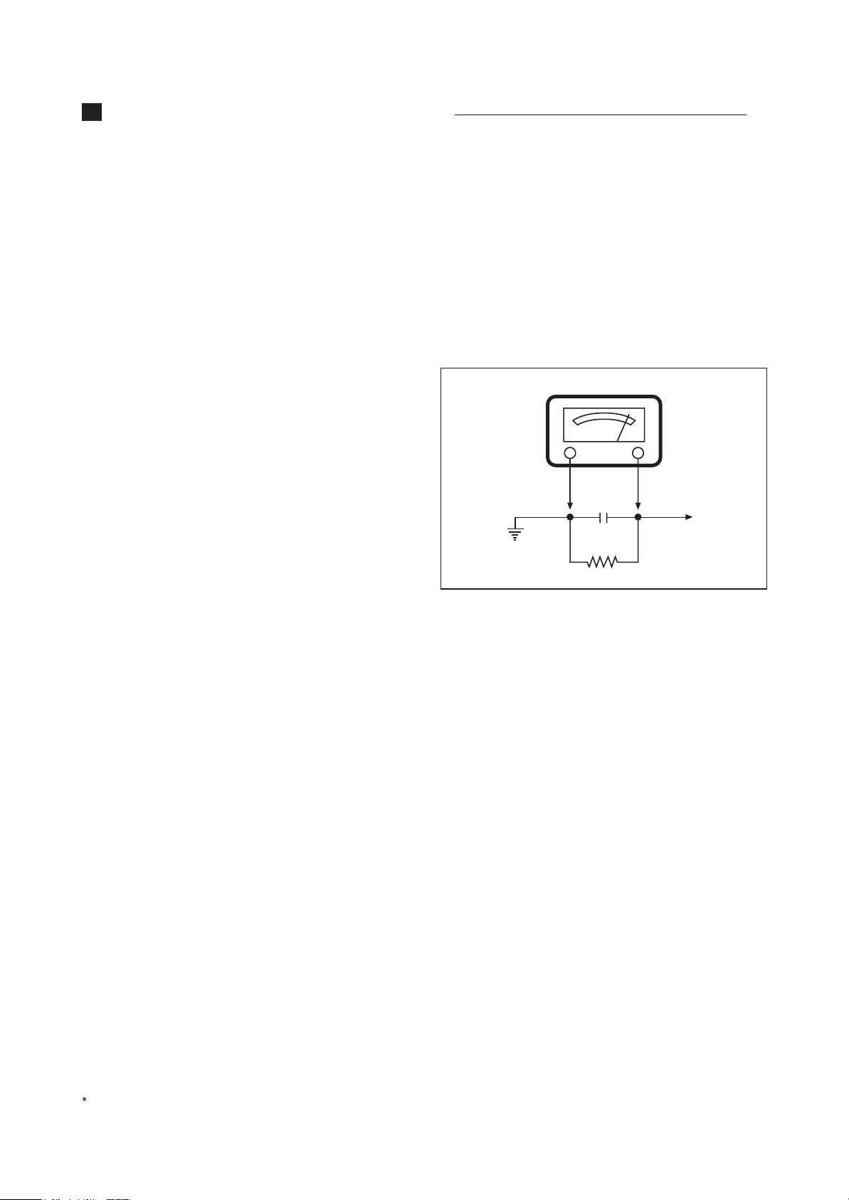
7. After re-assembly of the set always perform an A.C.
leakage test on all exposed metallic parts of the
cabinet, (the channel selector knob, antenna terminals,
handle and screws) to be sure the set is safe to operate
without danger of electrical shock. Do not use a line
isolation transformer during this test. Use an A.C.
voltmeter, having 5000 ohms per volt or more
sensitivity, in the following manner : connect a 1500
ohm 10 watt resistor, paralleled by a 15 mfd. 150V A.C.
type capacitor between a known good earth ground
(9water pipe, conduit, etc.) and the exposed metallic
parts, one at a time. Measure the A.C. voltage across
the combination of 1500 ohm resistor and 0.15 MFD
capacitor. Reverse the A.C. plug and repeat A.C.
voltage measurements for each exposed metallic part.
Voltage measured must not exceed 0.75 volts R.M.S.
This corresponds to 0.5 milliamp A.C. Any value
exceeding this limit constitutes a potential shock hazard
and must be corrected immediately.
Good earth ground,
such as the water
pipe, conduit, etc.
0.15µF
••
1500 OHM
10WATT
Place this probe
on each exposed
metal part.
GRAPHIC SYMBOLS :
The lightning flash with arrowhead symbol,
within an equilateral triangle, is intended to
alert the service personnel to the presence
of uninsulated
may be of sufficienty magnitude to
constitute a risk of electric shock.
The exclamation point within an equilateral
triangle is intended to alert the service
personnel to the presence of important
safety information in service literature.
Fuse symbol is printed on pcb adjacent to
the fuse, with
FUSE AS MARKED
explained in the service manual with the
following wording or equivalent.
CAUTION : FOR CONTINUED PROTECTION AGAINST
FIRE HAZARD, REPLACE ONLY WITH SAME TYPE 4A,
125V FUSE
PROTECTION PERMANENTE CONTRE LES RISQUES
D
INCENDIE, REMPLACER UNIQUEMENT PAR UN
FUSIBLE DE MEME TYPE ET DE 4A, 125V
and ATTENTION: AFIN D ASSU UNE
dangerous voltage that
RISK OF FIRE REPLACE
. The symbol is
.
SUBJECT : X-RADIATION
1. Be sure procedures and instructions to all service
personnel cover the subject of X-rays in current T.V.
receivers is the picture tube. However, this tube does
not emit X-rays when the high voltage is at the factory
specified level. The proper value is given in the
applicable schematic. Operation at higher voltages may
cause a failure of the picture tube or high voltage
supply and, under certain circumstances, may produce
radiation in excess of desirable levels.
2. Only factory specified C.R.T. anode connectors must
be used. Degaussing shields also serve as X-ray shield
in color sets. Always re-install them.
3. It is essential that the serviceman has available an
accurate and reliable high voltage meter. The
calibration of the meter should be checked perio dically against a reference standard. Such as the one
available at your distributor.
4. When the high voltage circuitry is operating properly
there is no possibility of an X-radiation problem. Every
time a color chassis is serviced, the brightness should
be run up and down while monitoring the high voltage
4

with a meter to be certain that the high voltage does not
exceed the specified value and that it is regulating
correctly. We suggest that you and your service
organization review test procedures so that voltage
regulation is always checked as a standard servicing
procedure. And that the high voltage reading be recorded
on each customer
5. When troubleshooting and making test measurements
in a receiver with a problem of excessive high voltage,
avoid being unnecessarily close to the picture tube and
the high voltage compartment.
Do not operate the chassis longer than is necessary to
locate the cause of excessive voltage.
6. Refer to HV, B+and Shutdown adjustment procedures
described in the appropriate schematic and
diagrams(where used).
s invoice.
SUBJECT : IMPLOSION
1. All direct viewed picture tubes are equipped with an
integral implosion protection system, but care should be
taken to avoid damage during installation. Avoid
scratching the tube. If scratched, replace it.
2. Use only recommended factory replacement tubes.
SUBJECT : TIPS ON PROPER
INSTALLATION
1. Never install any receiver in closed-in recess,
cubbyhole or closely fitting shelf space over, or close to
heat duct, or in the path of heated air flow.
2. Avoid conditions of high humidity such as : Outdoor
patio installations where dew is a factor. Near steam
radiators where steam leakage is a factor, etc.
3. Avoid placement where draperies may obstruct rear
venting. The customer should also avoid the use of
decorative scarves or other coverings which might
obstruct ventilation.
4. Wall and shelf mounted installations using a
commercial mounting kit, must follow the factory
approved mounting instructions. A receiver mounted to
a shelf or platform must retain its original feet(or the
equivalent thickness in spacers) to provide adequate
are flow across the bottom, bolts or screws used for
fasteners must not touch and parts or wiring. Perform
leakage test on customized installations.
5. Caution customers against the mounting of a receiver
on sloping shelf or a tilted position, unless the receiver
is properly secured.
6. A receiver on a roll-about cart should be stable on its
mounting to the cart. Caution the customer on the
hazards of trying to roll a cart with small casters across
thresholds or deep pile carpets.
7. Caution customers against the use of a cart or stand
which has not been listed by underwriters laboratories,
inc. For use with their specific model of television
receiver or generically approved for use with T.V.
the same or larger screen size.
s of
5

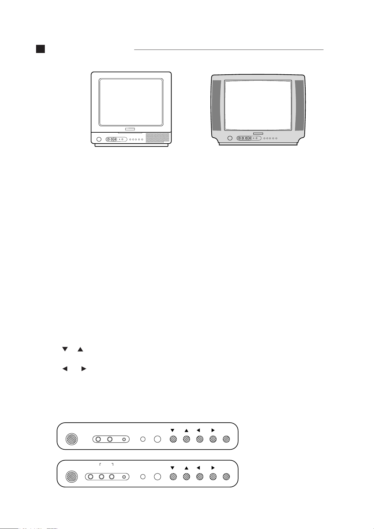
CONTROL VIEW
MONO MODEL
STEREO MODEL
Overview of Your Equipment
Your TV comes with a remote control. The section below summarizes the buttons, controls, and terminals that you
will use with your TV.
Your TV's Front Panel
1 POWER
Use this button to turn your TV on or off.
2 VIDEO IN jack
Use this jack to receive a video signal from another A/V component.
3 AUDIO IN jack
MONO MODEL use this jack to receive an audio signal from another A/V component. But, STEREO MODEL use
this jack to receive audio L/R signal from another A/V component.
4 EARPHONE IN jack
Use this jack to receive a audio signal from your TV.
5 STAND-BY (red) indicator
This indicator lights up when the power is off.
6 Remote control receiver
This receiver receives a signal from your remote control. Don’t block it.
7 CH
Use these buttons to change channels on your TV, or to select items in the menu system.
8 VOL
Use these buttons to change your TV’s volume, to activate selections in the menu system, or to change audio and
video settings.
9 MENU
Use this button to turn the TV’s menu system on and off.
MONO MODEL
POWER VIDEO AUDIO
STEREO MODEL
POWER VIDEO
AUDIO
L R
EARPHONE
EARPHONE
STAND-BY
STAND-BY
CH
CH
VOL
VOL
MENU
MENU
6

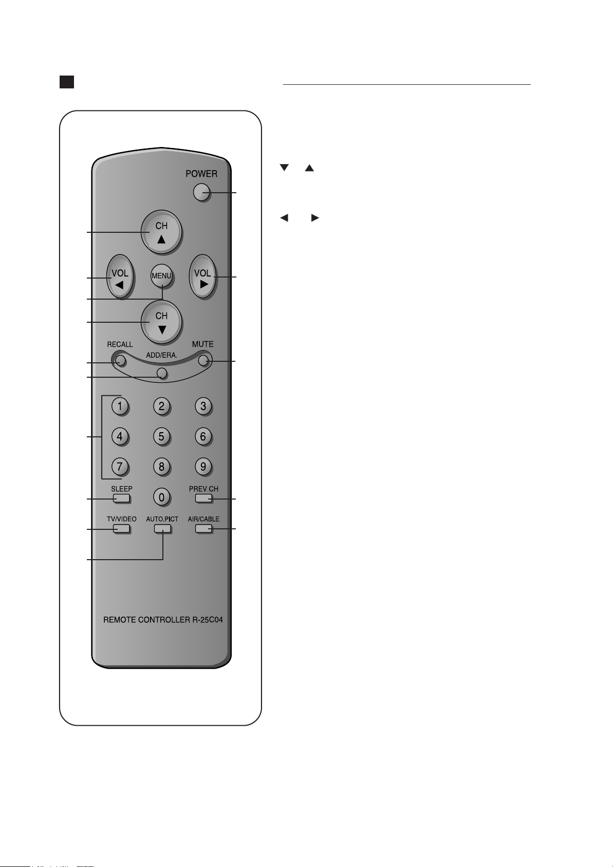
REMOTE CONTROL UNIT
1 POWER
2 CH
1
3 VOL
2
Use this button to turn your TV on or off.
Use these buttons to change channels on your TV, or select items in
the menu system.
Use these buttons to change your TV's volume, to activate selections
in the menu system, or to change audio and video settings.
3
4
2
5
6
8
9
11
12
4 MENU
3
5 RECALL
6 ADD/ERA.
7
7 MUTE
8 0-9
9 SLEEP
10PREV. CH
10
13
11 TV/VIDEO
Use this button to turn the TV's menu system on and off.
Press this button to display the channel number.
Use this button to add a channel to the TV's memory or erase the
channel from memory.
Use to turn the TV's sound on and off.
Use these buttons to change channels.
Use this button to program the TV to turn off after a certain time.
Press this button to return to the previous channel you were watching. If you have set Favorite Ch, this key operates to Favorite function.
Use this button to select TV or VIDEO mode.
12 AUTO. PICT
Press this button to return the TV's video settings to their original
level.
13 AIR/CABLE
Use the button to set up your TV to receive signals from an antenna
(AIR) or a cable system (CABLE).
7
CONTROL VIEW
MONO MODEL
STEREO MODEL
Overview of Your Equipment
Your TV comes with a remote control. The section below summarizes the buttons, controls, and terminals that you
will use with your TV.
Your TV's Front Panel
1 POWER
Use this button to turn your TV on or off.
2 VIDEO IN jack
Use this jack to receive a video signal from another A/V component.
3 AUDIO IN jack
MONO MODEL use this jack to receive an audio signal from another A/V component. But, STEREO MODEL use
this jack to receive audio L/R signal from another A/V component.
4 EARPHONE IN jack
Use this jack to receive a audio signal from your TV.
5 STAND-BY (red) indicator
This indicator lights up when the power is off.
6 Remote control receiver
This receiver receives a signal from your remote control. Don’t block it.
7 CH
Use these buttons to change channels on your TV, or to select items in the menu system.
8 VOL
Use these buttons to change your TV’s volume, to activate selections in the menu system, or to change audio and
video settings.
9 MENU
Use this button to turn the TV’s menu system on and off.
MONO MODEL
POWER VIDEO AUDIO
STEREO MODEL
POWER VIDEO
AUDIO
L R
EARPHONE
EARPHONE
STAND-BY
STAND-BY
CH
CH
VOL
VOL
MENU
MENU
6
REMOTE CONTROL UNIT
1 POWER
2 CH
1
3 VOL
2
Use this button to turn your TV on or off.
Use these buttons to change channels on your TV, or select items in
the menu system.
Use these buttons to change your TV's volume, to activate selections
in the menu system, or to change audio and video settings.
3
4
2
5
6
8
9
11
12
4 MENU
3
5 RECALL
6 ADD/ERA.
7
7 MUTE
8 0-9
9 SLEEP
10PREV. CH
10
13
11 TV/VIDEO
Use this button to turn the TV's menu system on and off.
Press this button to display the channel number.
Use this button to add a channel to the TV's memory or erase the
channel from memory.
Use to turn the TV's sound on and off.
Use these buttons to change channels.
Use this button to program the TV to turn off after a certain time.
Press this button to return to the previous channel you were watching. If you have set Favorite Ch, this key operates to Favorite function.
Use this button to select TV or VIDEO mode.
12 AUTO. PICT
Press this button to return the TV's video settings to their original
level.
13 AIR/CABLE
Use the button to set up your TV to receive signals from an antenna
(AIR) or a cable system (CABLE).
7
IMPORTANT SERVICE NOTES
1. X-RAY RADIATION PRECAUTION
1) Excessive high voltage can produce potentially
hazardous X-RAY RADIATION. To avoid such hazards,
the high voltage must not be above the specified limit.
The nominal value of the high voltage of this receiver is
24.4kv at zero beam current (minimum brightness)
under a 120V AC power source. The high voltage must
not, under any circumstances, exceed 27kv (28.5kv).
Each time a receiver requires servicing, the high
voltage should be checked following the HIGH
VOLTAGE CHECK procedure on page 6 of this
manual. It is recommended as a parts of the service
record. It is important to use an accurate and reliable
high voltage meter.
2) This receiver is equipped with X-RADIATION
PROTECTION circuit which prevents the receiver from
producing an excessively high voltage even if the
B+voltage increases abnormally. Each time the
receiver is serviced, X-RADIATION PROTECTION
circuit must be checked to determine that the circuit is
properly functioning, following the X-RADIATION
PROTECTION CIRCUIT CHECK procedure on page 6
of this manual.
3) The only source of X-RAY RADIATION in this TV
receiver is the picture tube. For continued X-RAY
RADIATION protection, the replacement tube must be
exactly the same type tube as specified in the parts list.
4) Some parts in this receiver have special safety-related
characteristics for X-RAY RADIATION protection. For
continued safety, parts replacement should be
undertaken only after referring to the PRODUCT
SAFETY NOTICE below.
2. SAFETY PRECAUTION
WARNING
: Service should not be attempted by anyone
unfamiliar with the necessary precaution on this receiver.
The following are the necessary precaution to be
observed before servicing.
1) Since the chassis of this receiver has hazardous
potential to ground whenever the receiver is plugged in
(floating chassis), an isolation transformer must be
used during servicing to avoid shock hazard.
2) Always discharge the picture tube anode to the CRT
conductive coating the picture tube. The picture tube is
highly evacuated and if broken, glass fragments will be
violently expelled. Use shatterproof goggles and keep
picture tube away from the body while handling.
3) When placing chassis in the cabinet, always be certain
that all the protective devices are put back in place,
such as; nonmetallic control knobs, insulating covers,
shields, isolation resistor-capacitor network, etc.
4) Before returning the set to the customer, always
perform an AC leakage current check on the exposed
metallic parts of the cabinet, such as antennas,
terminals, screw-heads, metal overlays, control shafts
etc. to be sure the set is safe to operate without
danger of electrical shock. Plug the AC line cord
directly into a 120V AC outlet (do not use a line isola-
Minimum brightness
tion transformer during this check). Use an AC
voltmeter having 5000 ohms per volt or more sensitivity in the following manner.
Connect at 1500 ohm 10 watt resistor, paralleled by a
0.15 mfd. AC type capacitor, between a known good
earth ground (water pipe, conduit etc.) and the exposed
metallic parts, one at a time. Measure the AC voltage
across the combination of 1500 ohm resistor and 0.15
mfd capacitor. Voltage measured must not exceed 0.3
volts RMS. This corresponds to 0.2 millliamp. AC. Any
value exceeding the limit constitutes a potential shock
hazard and must be corrected immediately.
AC VOLT METER
0.15MFD
Place this probe
on each exposed
metallic part.
Good earth ground
such as d water
pipe, conduit, etc.
1500 ohm
10watt
3. PRODUCT SAFETY NOTICE
Many electrical and mechanical parts in this chassis have
special safety-related characteristics. These
characteristics are often passed unnoticed by a visual
inspection and the protection afforded by them cannot
necessarily be obtained by using replacement
components rated for higher voltage, wattage, etc.
Replacement parts which have these special safety
characteristics are identified in this manual and its
supplements; electrical components having such features
are identified by shading on the schematic diagram and
the parts list.
Before replacing any of these components, read the parts
list in this manual carefully. The use of substitute
replacement parts which do not have the same safety
characteristics as specified in the parts list may create Xray radiation or other hazards.
4. SERVICE NOTES
1) When replacing parts or circuit boards, clamp or bend
the lead wires to terminals before soldering.
2) When replacing a high wattage resistor (metal oxide
film resistor) in the circuit board, keep the resistor min
1/2 inch away form circuit board.
3) Keep wires away from high voltage or high temperature
components.
8
9

GENERAL ADJUSTMENTS
1. GENERAL
In the majority of cases, all color televisions will need only
slight touch-up adjustment upon installation. Check the
basic characteristics such as height, focus and sub- basic
characteristics such as height, focus and sub- bright.
Observe the picture for good black and white details
without objectionable color shading. If color shading is
evident, demagnetize the receiver. If color shading still
persists, perform purity and convergence adjustments.
This should be all that is necessary to achieve Optimum
receiver performance.
2. SCREEN ADJUSTMENT
1) Turn on TV
2) Press the S2 key of Service Remocon to make the One
Horizontal Line
3) Adjust the Screen adj. VR of FBT so that the One
Horizontal Line may be cut off.
4) Press the S2 key of Servic Remocon to be normal.
3. FOCUS ADJUSTMENT
1) Receive the Retma Pattern.
2) Adjust the FOCUS adj. VR to optain the clearest
picture.
4. HORIZONTAL CENTER ADJUSTMENT
1) Receive the Retma Pattern.
2) Press the S6(59H) key of Service Remocon, select
H.Phase, then adjust step so that the L/R Width of
picture be alike.
3) Press the RECALL key to store.
4) Initial value of D.P : 5
7. X-RADIATION PROTECTION CIRCUIT TEST
When service has been performed on the horizontal
deflection system, high voltage system or B+system. the
X-RADIATION protection circuit must be tested for proper
operation as follows:
1) Operate receiver for at least 15 minutes at 120V AC
line.
2) Adjust all customer controls for normal picture and
sound.
3) Short R411(X-RAY Short test), and remove short clip.
4) If the operation of horizontal osc. does not stop in step
The circuit must be repaired, before the set is returned
to the customer.
8. White balance ADJUSTMENT
1) Press the S8 key of SERVICE REMOCON, select W/B
2) Adjust the R/G/B BIAS of Low BEAM in order that the
R/G/B BIAS of Low BEAM may meet with coordinates.
3) Adjust the R/B DRIVE of High BEAM in order that the
R/B DRIVE of High BEAM may meet with coordinates.
4) Confirm the LOW BEAM, HIGH BEAM alternately.
5) Press the RECALL key to store.
9. SUB-BRIGHTNESS ADJUSTMENT
1) Receive the Retma Pattern.
2) Press the S9(5CH) key of Service Remocon, adjust
Bright in order that the gradation pattern may set 18%.
3) Press the RECALL key to store.
4) Initial value of D.P :25
5. VERTICAL CENTER ADJUSTMENT
1) Receive the Retma Pattern.
2) Press the S6(59H) key of Service Remocon, select
V.DC, then adjust V.DC so that the horizontal line of
RETMA PATTERN’S center may meet with the
mechanical CENTER of CRT.
3) Press the RECAL key to store.
4) Initial value of D.P:35
6. VERTICAL HIGHT ADJUSTMENT
1) Receive the Retma Pattern.
2) Press the S6(59H) key of Service Remocon, select
V.Size, then adjust V.Size so that the center of
circumference of big circle may meet with the upper
and lower sides of the screen.
3) Press the RECALL key to store.
4) Initial of value of D.P :35
10
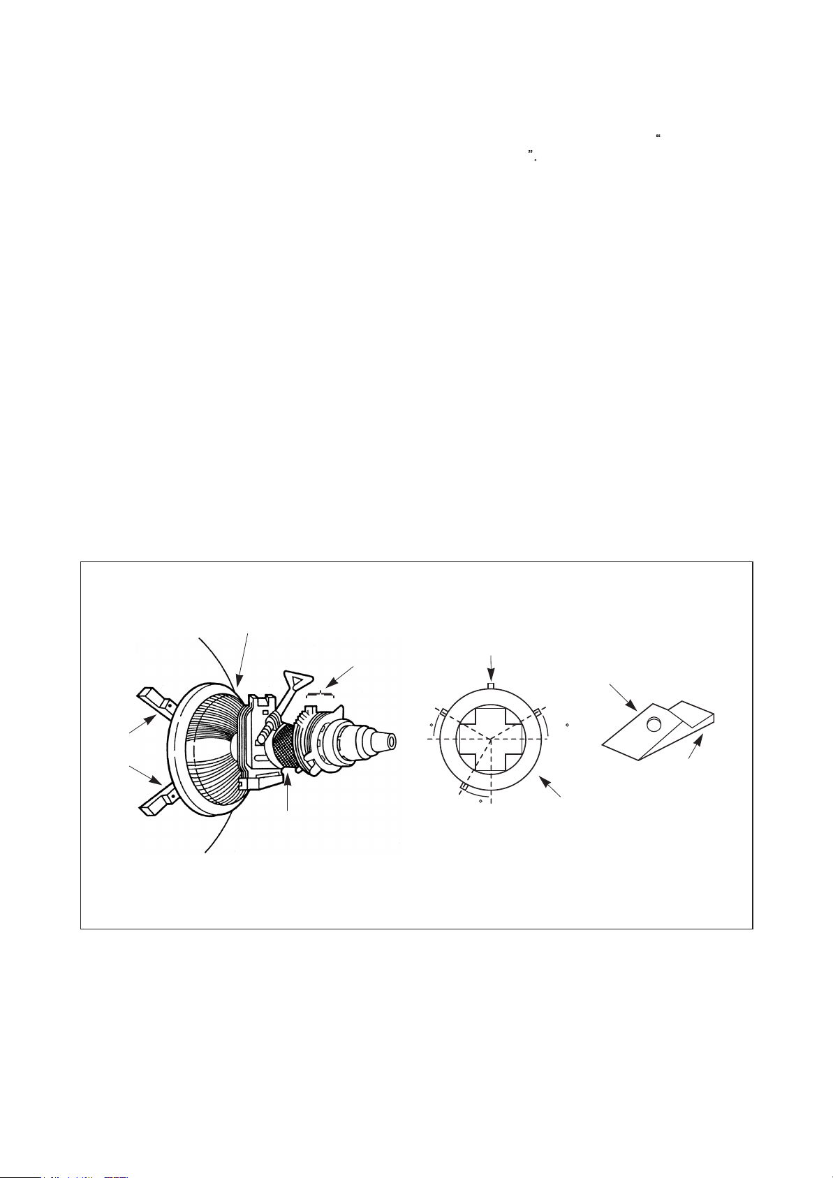
10. CONVERGENCE MAGNET ASSEMBLY
POSITIONING
If Convergence magnet assembly and rubber wedges
need mechanical positioning follow figure 2.
10-1. COLOR PURITY ADJUSTMENT
NOTE
1) Demagnetize the picture tube with a degaussing coil.
2) Adjust the CONTRAST and BRIGHTNESS controls to
3) Adjust RED and BLUE Bias controls Service Remocon
4) Loosen the clamp screw holding the yoke, and slide the
5) Remove the Rubber Wedges.
6) Rotate and spread the tabs of the purity magnet (See
7) Move the yoke slowly forward until a uniform green
: Before attempting any purity adjustments, the
receiver should be operated for at least 15
minutes.
maximum
to provide only a green raster. Adjust the GREEN BIAS
control Service Remocon if necessary.
yoke backward to provide vertical green belt(zone)in
the picture screen.
figure 2) around the neck of the picture tube until the
green belt is in the center of the screen. At the same
time, center the raster vertically.
screen is obtained. Tighten the clamp screw of the yoke
temporarily.
8) Check the purity of the red and blue raster by adjusting
the BIAS controls.
9) Obtain a white raster, referring to
ADJUSTMENT
10) Proceed with convergence adjustment.
White Bodance
RUBBER
WEDGES
PICTURE TUBE
DEFLECTION
YOKE
GLASS CLOTH
TAPE
CONVERGENCE
MAGNET ASS'Y
TEMPORARY
MOUNTING
30 30
30
Fig. 2 Rubber Wedges Location
RUBBER
WEDGES
ADHESIVE
DEF.
YOKE
11

10-2. CONVERGENCE ADJUSTMENTS
NOTE
: Before attempting any purity adjustments, the
receiver should be operated for at least 15
minutes.
A. CENTER CONVERGENCE ADJUSTMENT
1) Receive crosshatch pattern with a crosshatch signal
generator.
2) Adjust the BRIGHTNESS and CONTRAST Controls for
a good picture.
3) Adjust two tabs of the 4-Pole Magnets to change the
angle between them (See Fig. 3) and superimpose red
and blue vertical lines in the center area of the picture
screen. (See Fig. 4)
4) Turn both tabs at the same time keeping their angles
constant to superimpose red and blue horizontal lines
at the center of the screen. (See Fig. 4)
5) Adjust two tabs of 6-Pole Magnets to superimpose
red/blue line with green on top of each other. Adjusting
the angle affects the vertical lines and rotating both
magnets affects the horizontal lines.
6) Repeat adjustments 3), 4), 5) keeping in mind red,
green and blue movement, because 4-Pole Magnets
and 6-Pole Magnets interact and make dot movement
complex.
B. CIRCUMFERENCE CONVERGENCE ADJUSTMENT
: This adjustment requires Rubber Wedge Kit.
NOTE
1) Loosen the clamping screw on deflection yoke to allow
the yoke to tilt.
2) Place a wedge as shown in figure 2 temporarily. (Do
not remove cover paper on adhesive part of the
wedge.)
3) Tilt front of the deflection yoke up or down to obtain
better convergence in circumference. (See Fig. 4) Push
the mounting wedge into the space between picture
and the yoke to hold the yoke temporarily.
4) Place other wedge into bottom space and remove the
cover paper to stick.
5) Tilt front of the yoke right or left to obtain better
convergence in cicumference. (See Fig. 4)
6) Hold the yoke position and put another wedge in either
upper space. Remove cover paper and stick the wedge
on picture tube to hold the yoke.
7) Detach the temporarily mounted wedge and put it in
another upper space. Stick it on picture tube to fix the
yoke.
8) After placing three wedges, re-check overall
convergence. Tighten the screw firmly to hold the yoke
tightly in place.
9) Stick 3 adhesive tapes on wedges as shown in figure32.
4-POLE
PURITY
MAGNETS
MAGNETS
4DJUST THE
ANGLE
(VERTICAL
CONSTANT
LINES)
ROTATE TWO TABS AT
THE SAME TIME
CONVERGENCE MAGNET ASSEMBLY
BLUE
BLUE
RED
RED
RED/BLUE
GRN
RED/BLUE
Fig. 3
GRN
B G R
R
G
B
R G B
(HORIZONTAL LINES)
ADJUSTMENT OF MAGNET
B
G
R
B
G
R
BGR
4-Pole Magnets Movement 6-Pole Magnets Movement Incline the Yoke up(or down) Incline the Yoke right(or left)
Center Convergence by Convergence Magnets Circumference Convergence by DEF. Yoke
BGR
R
G
B
Fig. 4 Dot Movement Pattern
12

11. APC DET & PLL Tunning ADJUSTMENT
1) Receive the signal of RF 100% Full Color bar 85dBuV.
2) Press the S5(58H) key of Service Remocon, then execute Auto adj Start.
3) Confirm the OSD of Auto adj. OK.
4) If it was Auto adj. NG, Receive the signal of adjacent channel, then perform Auto adj. Start again.
5) Press the RECALL key to store. (Initial value of D.P APC:30, PLL:40)
12. RF AGC ADJUSTMENT
1) Receive the attenuate signal of RF 100% Full Color Bar 60dBuV.
2) Connect Scope to TP101(OR P101).
3) Press the S5 key of Service Remocon, select RF AGC.D, then adjust the maximum voltage of Scope to attenuate 1V.
(Initial value of the maximum voltage : About 7V)
For example if initial maximum voltage is 7V, adjust it to 6V
4) Press the RECALL key to store. (Initial value of D.P :25)
13). Stereo/Sap ADJUSTMENT
1) Receive the ZENITH MTS signal of 1KHz(OR 3KHz)CH.
2) Press the S10(5D) key of Service Remocon, select Auto Off, then execute Auto on.
3) Press the RECALL key to store.
4) Slect L ONLY OR R ONLY Channel, then confirm stereo Seperation.
If you have only User Remocon, A way of using is as follows;
1) Press the 1 key
2) Press the MUTE key
3) Press the RECALL Key
4) Press the MUTE key then the Service mode will appear.
5) Use the CH buttons to select the mode you wish to adjust.
1 MUTE RECALL MUTE
13
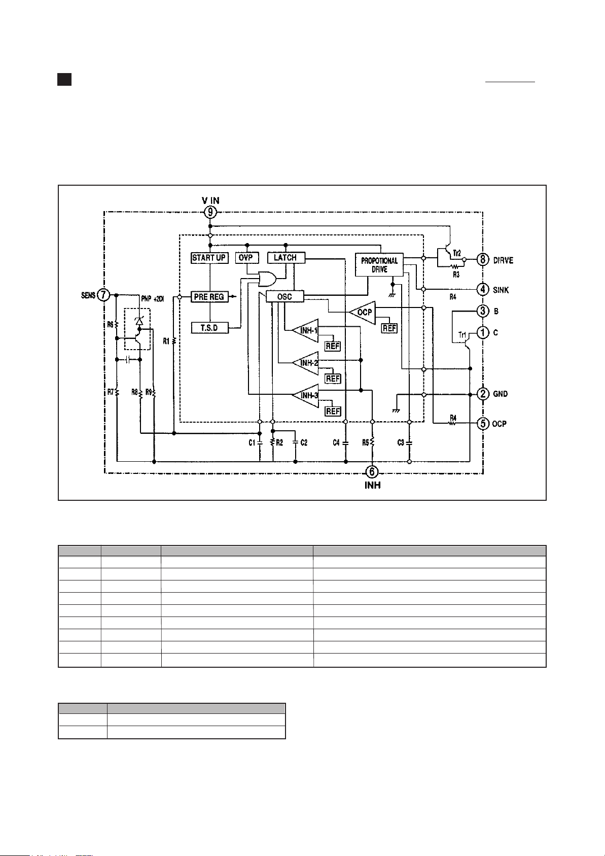
OPERATION CHARACTERISTICS OF POWER BLOCK(I801)
This chassis designed for free voltage(AC 100V ~ AC 220V) power. power block contains power IC, SMPS
transformer and several passive components.
The power IS STR-S5707 has power transistor. oscillator circuit, voltage comparator circuit, thermal protection
circuit, OCP(over current protection)circuit inside.
1. STR-S5707 BLOCK DIAGRAM
2. PIN DESCRIPTION
PIN NO SYMBOL NAME FUNCTION
1 C COLLECTOR POWER TRANSISTOR COLLECTOR
2 GND GROUND GROUND(POWER TRANSISTOR EMITTER)
3 B BASE POWER TRANSISTOR BASE
4 SINK SINK BASE URRENT(Is) INPUT
5 OCP OVER CURRENT PROTECTION OVERCURRENT SENSING SIGNAL INPUT
6 INH INHIBIT/LATCH SYNC, OFF TIME/LATCH CIRCUIT CONTROL INPUT
7 F/B(SENS) FEED BACK(SENSING)INPUT CONSTANT VOLTAGE CONTROL SIGNAL INPUT
8 DRIVE DRIVE BASE DRIVE CURRENT(Id)OUTPUT
9 Vin Vin SUPPLY VOLTAGE FOR CONTROL CIRCUIT
3. OTHER FUNCTION
Symbol Function
OVP Built-in Overvoltage Protection Circuit
TSD Built-in Thermal Shutdown Circuit
14
4. EXPLANA TION OF CIRCUIT OPERATION
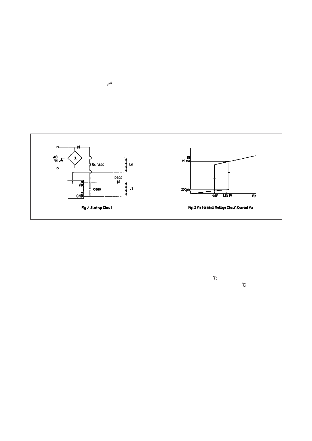
1) VINterminal, start-up circuit
A Start-up circuit is to start and stop a operation of a control IC by detecting a voltage appearing at a VINterminal(pin-
9).At start up of a power supply, when a voltage at the VINterminal reaches to 8V by charging up C809 by the function
of a start-up resistor, Rs, a control circuit starts operating by the function of the start-up circuit. As shown in Fig. 2, since
a circuit current is suppressed 200 maximum (at VIN= 7.5V) until the control circuit starts its operation.
After the control circuit starts its operation, power source is obtained by smoothing voltage appearing at L1 winding.
Once the control circuit starts operating, as its voltage doesn’t reach the fixed voltage at once, VINterminal voltage
starts dropping. However, as a shut-down voltage is set low(at 4.9V), while VINterminal voltage reaches a shutdown
voltage, L1 winding voltage reaches the fixed voltage earlier so that the control circuit can continue on operating.
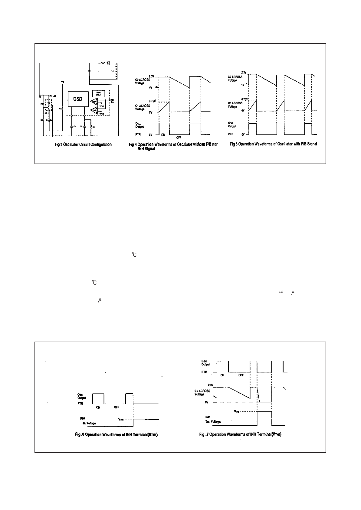
2) Oscillator, F/B terminal voltage (Pin #7)
A oscillator generates pulse signals which turns a power transistor on and off by making use of charge and discharge of
C1 and C2 incorporated in the Hybrid IC.
Constant voltage control of a switch-mode power supply is performed by changing both ON-time and OFF-time except
when the load is light (ex. remote control stand-by mode of TVs).
Fig. 4 shows how the oscillator works when the Hybrid IC independently operates (with no F/B nor INH signals). When
the power thransistor is on, C2 Is charged to the set voltage (approx 2.3V at Ta = 25 ). On the other hand, C1 starts
charging up through R1 from almost OV and the voltage across C1 reaches approx. 0.75V (Tc = 25 ). the output from
the oscillator is reversed and the power transistor turns off. At the same time C1 is quickly discharged by the function of
a internal circuit of the oscillator and the voltage across it decreases to almost OV. When the power transistor turns off,
C2 starts discharging through R2 and the voltage across C2 decreases with the inclination determined by the product of
C2 decreases to about 1V. the output from the oscillator is reversed again and the transistor consequently turns on. The
power transistor continues turning on and off by repeating the above-mentioned operations.
15
As the circuit in Fig. 3 shows, the ON-time is controlled by changing a current charged by C1, which is as the result of
that the detection winding (L1), which detects a change of voltage in a secondary side, connected to the sensing
terminal (Pin No. 7) has the current in accordance with an output signal from an output voltage detection circuit (an error
amplifier) built in. As an AC input voltage to the power supply gets the higher and a load current the smaller, the current
flowing to the SENS terminal gets the larger, and the ON-time gets the shorter.
3) Function of INH terminal (Pin #6), control OFF-time
Signal to the INH terminal is used as inputs to COMP.1 and COMP.2 inside of the control IC.A threshold voltage of
COMP.1 V
is in OFF mode) when a voltage at the INH terminal reaches the V
lower than V
set at 1.5V (Ta = 25 ). When the INH terminal voltage reaches V
TH
is set at 0.75V (Ta = 25 ) and an input signal to a drive circuit becomes almost OV (the power transistor
1
TH
. As long as the INH terminal voltage does not get
1
TH
. the power transistor sustains OFF mode. On the other hand, a threshold voltage of COMP.2 V
1
TH
, an output from COMP.2 reverses and, as a
2
TH
2
, is
result, C2, the OFF-tim of the oscillator which has been determined by the product of C2 and R2 ( 55 sec) can be
quicker up to approx. 2 sec. As long as the INH terminal voltage does not get lower than V
TH
, A Voltage across C2
2
stays at almost 0V and a output from the oscillator keeps the power transistor being on. The relation between the INH
terminal voltage and the function of the oscillator described above is shown in Fig. 6 and FIg. 7
16
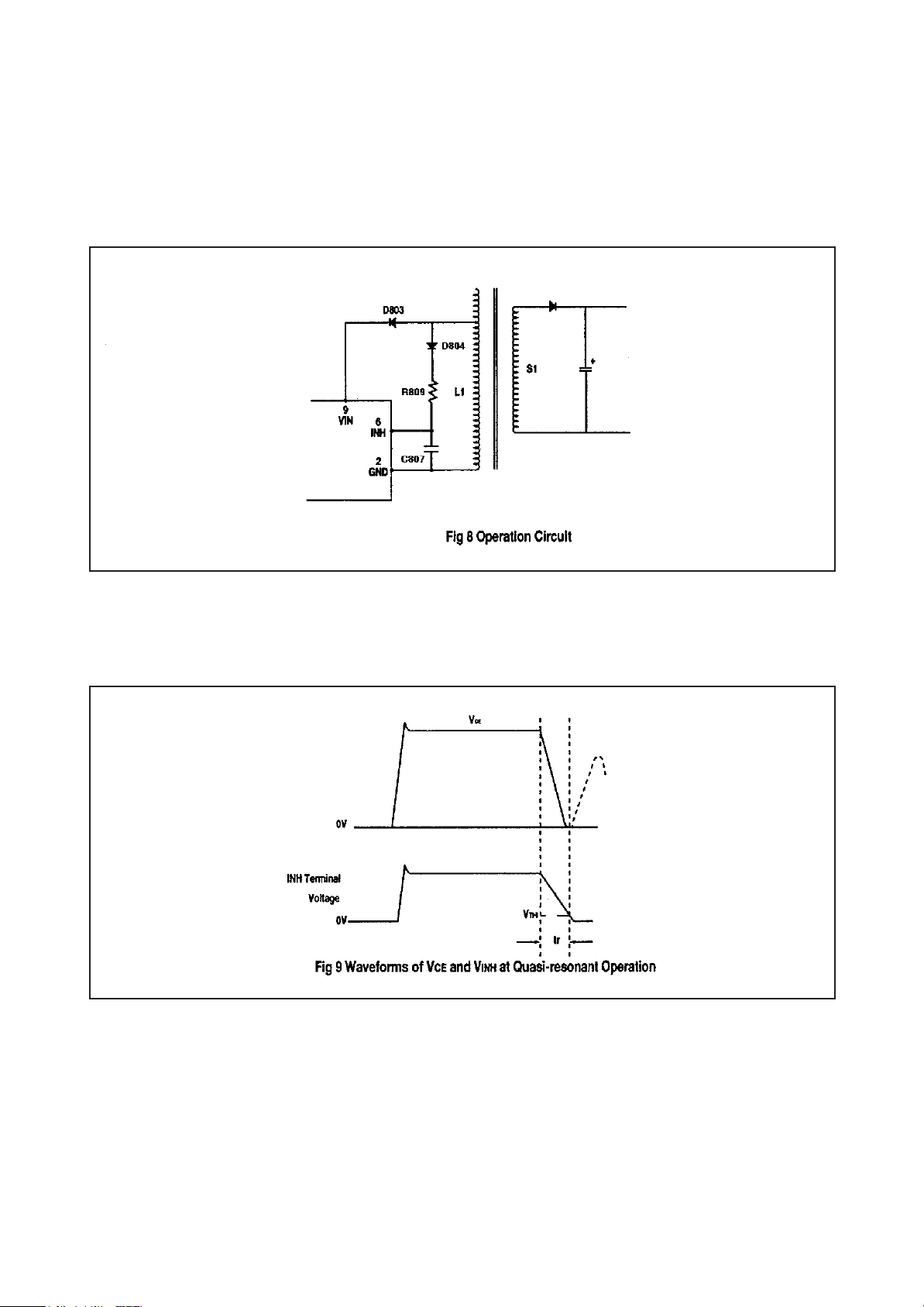
4) Quasi-resonant operation
By inputting a voltage signal which is synchronized with the energy discharge time of a secondary winding of a
transformer to the. INH terminal, quasi-resonant operation can be achieved. As shown in Fig. 8, the voltage of L1
winding which is synchronized. with the energy discharge time of a secondary winding. S1. shall be input to the INH
terminal through D804 and R809. Since V
TH
is set at 1.5V typical, a voltage at the INH terminal. V
2
INH
, shall be set at
Fig. 9 shows waveforms of VCE, Ic and V
INH
of the transistor, voltage across C807 in the oscillator as well as an output
from the oscillator when operating in quasi-resonant mode.
when the power transistor turns off and a voltage than V
and then starts charging again. Even after the discharge of energy of a secondary winding is completed, V
immediately increases. When it gets lower than V
impedance of the IC and C
INH
, has past, the transistor turns on.
TH
is applied to the INH terminal, C807 immediately discharges
2
INH
does not
TH
after the time,tr, which is determined by the production of internal
2
17
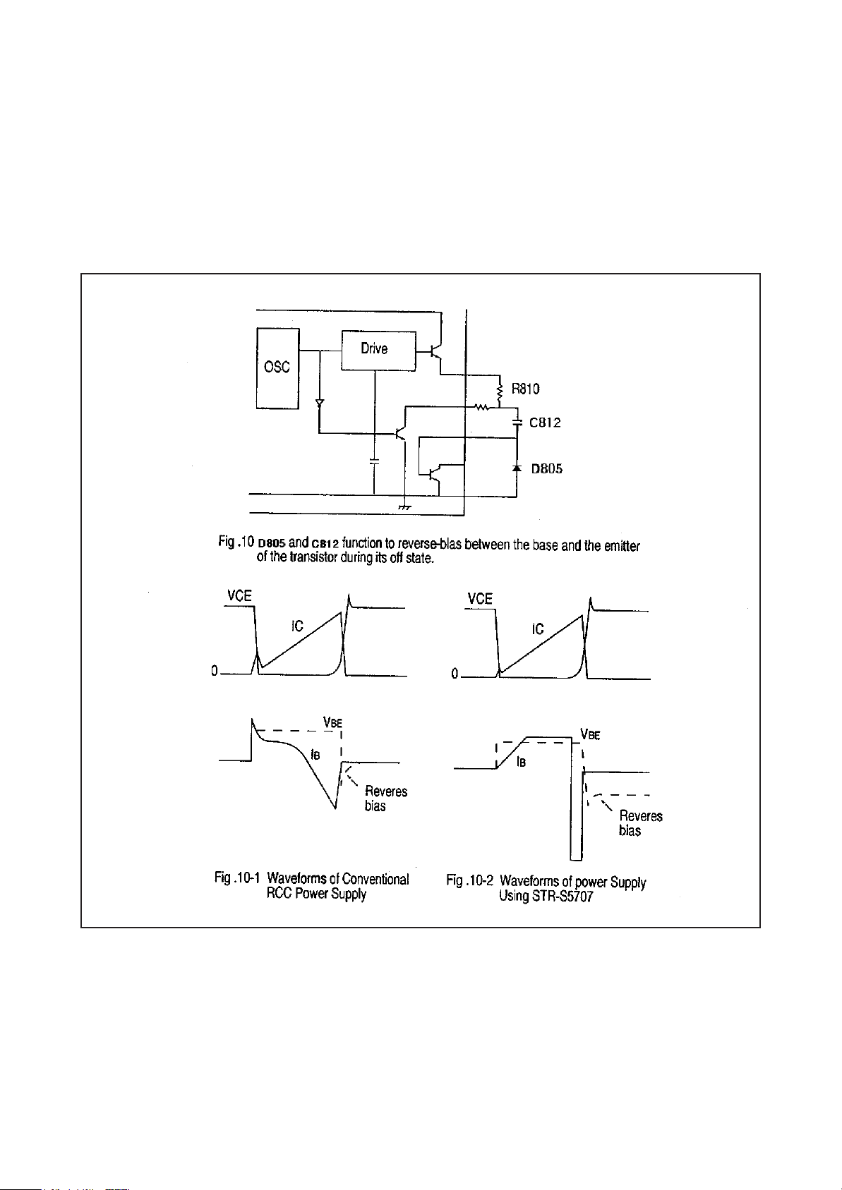
5) Drive circuit
The STR-S5707 applies the proportional drive system in order to minimize turn-on and saturation loss, and storage
time. In the conventional RCC system, turn-on loss and switching noise due to the surge current appearing when the
power transistor turns on are high as because the transistor is driven by the drive current shown in FIg. 10-1. In
addition, since is decreases linearly when the transistor turn off and a peak value of l
long and the V
CE
voltage is high, which results in large turn-off loss. The circuit and the waveforms of the proportional
(
SAT
)
B
is not large, the storage time is
2
drive system which is applied to the STR-S5707 in order to reduce these switching loss and shorten the storage time
are shown in Fig. 10-2 respectively.
18
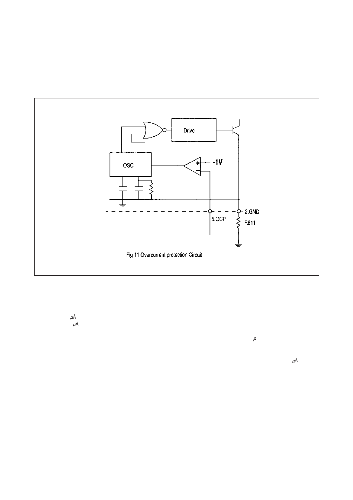
6) OCP (overcurrent protection)function
Overcurrent protection is performed pulse by directly detecting collector current of the power transistor.
Configuration of the OCP circuit is shown in. Detecting voltage is set to-1V below a reference point of GND (ground). In
addition, since the detecting voltage is set by a comparator, very stable characteristics against temperature is achieved
and drift of the deteting voltage against temperature change is almost OV.
7) Latch circuit
It is a circuit which sustains an output from the oscillator low and stops operation of the power supply when overvoltage
protection (OVP) circuit and thermal shutdown (TSD) circuit are in operation. As the sustaining current of the latch
circuit is 500 maximum when VINterminal voltage is 4V. the power supply circuit sustains the off state as long as
current of 500 maximum flows to VINterminal from a start-up resistor. In order to prevent a malfunction to be caused
by a noise and so on, delay time is provided by C1 incorporated in the IC and, therefore, the latch circuit operates when
the OVP of TSD circuit is in operation, of an external signal input is provided. for about 10 sec or longer. In addition,
even after the latch circuit start operating, the constant voltage regulator (Reg) circuit is in operation and the circuit
current is at high level. As a result. VINterminal voltage rapidly decreases. When V
than the shutdown voltage, V
reaches the ON-state voltage. VIN(ON), (8V typical), V
IN
(OFF), (4.9V typical), it starts in-creasing as the circuit current is below 500 . When it
terminal voltage starts decreasing because the circuit current
IN
terminal voltage becomes lower
IN
increases again.
19
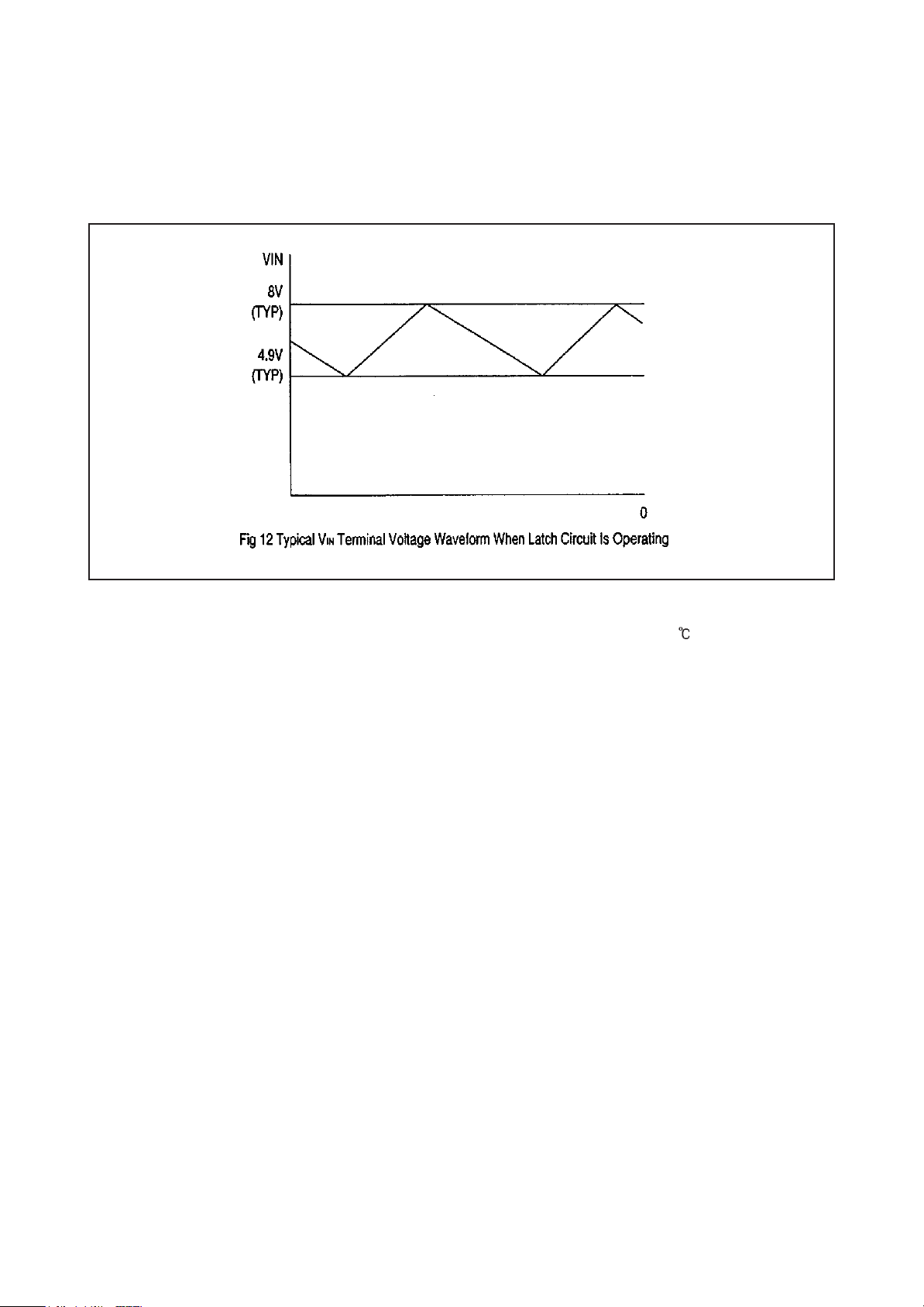
when the latch circuit is on. VINterminal voltage increases and decreases with-in the range from 4.9V typical to 8V
typical and is prevented from abnormally rising. Fig. 12 shows an example of VINterminal voltage waveform.
Cancellation of the latch-is done by decreasing VINterminal voltage below 3.3V. The power supply can be restarted
disconnecting an AC input to the power supply once.
8) Thermal shutdown, circuit
It is a circuit to trigger the latch circuit when the frame temperature of the IC exceeds 150 (typical). Although the
temperature is actually sensed at the control chip. lt works against overheating of the power transistor as the power
transistor and the control IC are mounted on the same lead frame.
9) Overvoltage protection circuit
lt is a circuit to trigger the latch circuit when Vin terminal voltage exceeds 11V (typical). Although it basically functions as
protection of Vin terminal against overvoltage, since Vin terminal is usually supplied from the drive winding of the
transformer and the voltage is proportional to the output voltage, it also functions against the overvoltage of secondary
output which causes when the control circuit opens or in some other events.
20
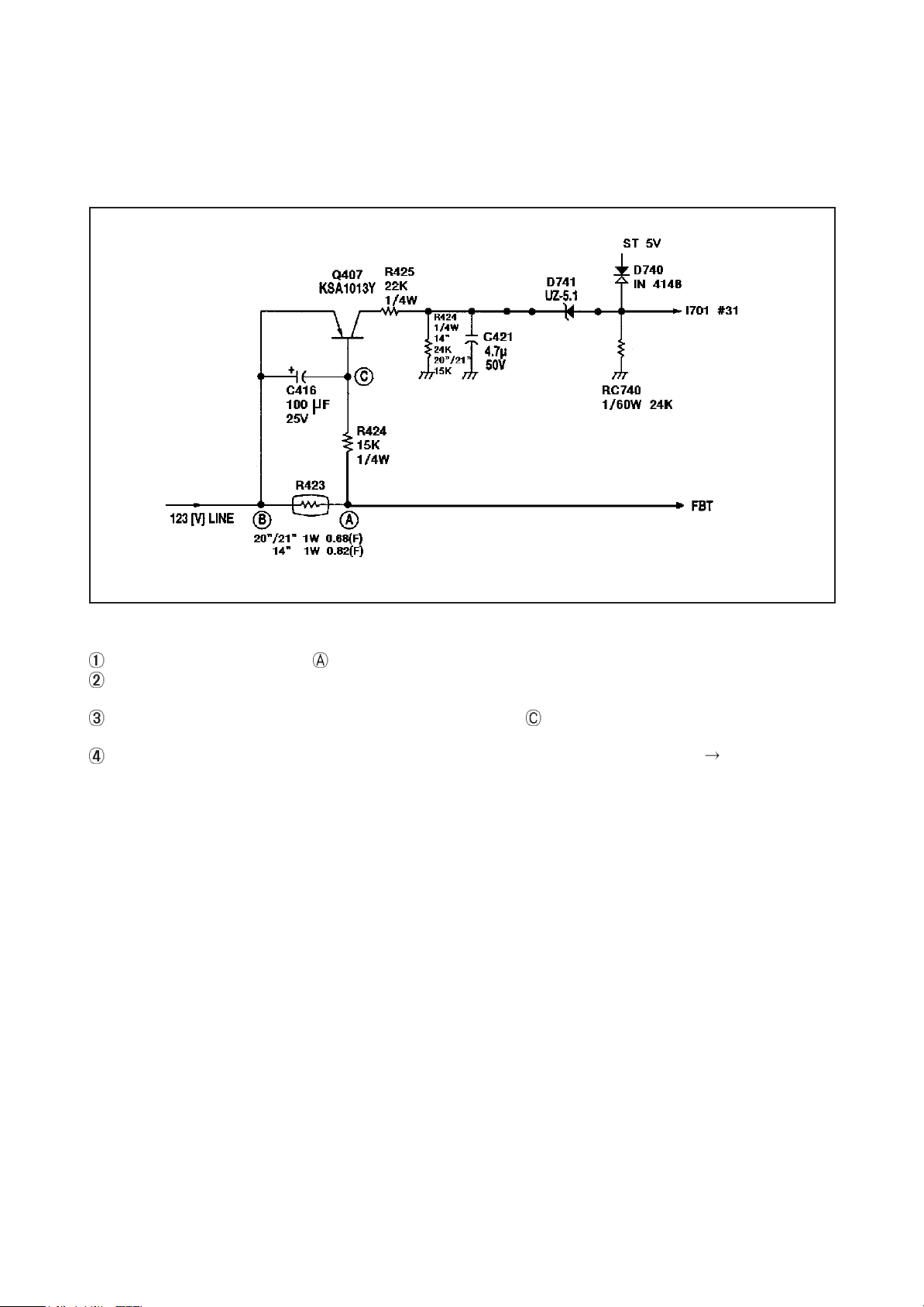
5. OCP (OVER CURRENT PROTECTION) CIRCUIT
This circuit is designed to protect the circuit from over current due to overload occurred at the rear of 123[V] line
1) CONFIGURATION OF OCP CIRCUIT
2) EXPLANATION OF THE OPERATION
There is very little voltage drop at R423 of 123[V] line.
In case that the overload occurs at the rear of 123[V] line, the increase of the voltage drop at R423 bring down the base
voltage of the Q407 os as to drive the Q407
Because of the overload at the rear of the R423, the voltage of the point decreases. And this makes Q407 turn on
so that a voltage is applied to the #31 of l701.
In case that OCP operates by the #31 of the l1701, the set is protected by power off (#42 of l1701 LOW).
21
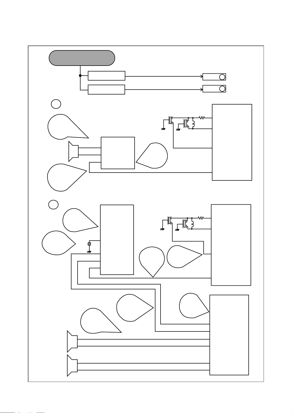
TROUBLE SHOOTING CHART S
NO POWER (NO OUTPUT SECOND POWER)
I801
VIN 9
SENS 7
COLEECTO R 1
CHECK
F801
250V A
L801
LINE
FIL TER
CHECK
R801
R CEMENT
CHECK
SUPPLY
VOLTAGE
CHECK
FEED BACK
INPUT
D801 +
PBS208GU
R802
DON'T OPERATE POWER ON
T801
SMPS
TRANS
I1702
VDD 8
CLK 6
DATA 5
CHECK
CLOCK
PULSE
ST-BY: OV
POER ON:
I501
H. VCC 21
BUS 43
INTERFAC E 44
H. OUT 23
CHECK
DC 5V
CHECK
DATA
PULSE
ST-BY: 5V
POWER ON
CHECK
H-OUT
PUSLE
ST-BY: OV
POWER ON:
CHECK
DC 5V
CHECK
DC 5V
CHECK
VOLT.
RC401
X701
I701
1 EE-CLK
3 M-CLK
4 M-DATA
10
11
12 VDD
16 RESET
42 POWER
ST-BY: L
POWER ON: H
T401
22

NO PICTURE
CHECK THE WAVE FORM OF
U101 #IF
A
CHECK
VIDEO SIGN AL
4.6V
2.6V
2Vp-p
1.6V
4.6V
Z502
3Vp-p
RC539
L505
BRIGHT
CONTRAST
OK
NO
I501
45 VIDEO OUTPUT
47 INTERNAL
VIDEO INPUT
42 SELECT
VIDEO OUTPUT
32 ABL
33 ACL
30 R OUTPUT
29 G OUTPUT
28 B OUTPUT
CHECK
R/G/B SIGN AL
4
CHECK
7.4V LINE
GOTO
GOTO
T 402
A
B
HEATER
180 V
ABL
RC549
CHECK
HEATER
VTG 6.3Vms
D405
D402
CHECK
180V
LINE
CC511
0.1MF
B
CHECK
DC 5V, 9V
33V LINE
SF 501
SAW FILTER
CHECK
RF AGC OUTPUT
VTG
DC 5V - 8V
U101
IF
5V
9V
33V
AGC
CL
DA
EN
I501
11
10
6 RF AGC
OUTPUT
I702
5 DATA
6 CLK
CHECK
CLK, EN, DATA
SIGNAL
I701
5 T-CLK
6 T-DATA
7 M-EN
23
NO SOUND
C
CHECK
AUDIO
OUTPUT
SIGNAL
CHECK
AUDIO
INPUT
SIGNAL
D
CHECK
DC 9V
MONO MODEL
STEREO MODEL
I602
8 -A-OUT
6 +A-OUT
3 A-IN
I601
23
2
CHECK
SOUND B+
DC 12V
Z503 Z502
Z2
Z1 RC1
RC539
L505
L1
GOTO
GOTO
C
D
45 VIDEO OUTPUT
47 INTERNAL
VIDEO INPUT
49 SOUND IF
INPUT
51 AUDIO OUTPUT
45 VIDEO OUTPUT
I501
I501
CHECK
RESONATOR
Z601
CHECK
AUDIO
OUTPUT
SIGNAL
30 CES
1 OUT L
42 OUT R
24 COMP IN
CHECK
R/L-INPUT
SIGNAL
CHECK
INPUT
COMP
SIGNAL
CHECK
SOUND IF
SIGNAL
CHECK
SOUND B+
DC 12V
47 INTERNAL
VIDEO INPUT
49 SOUND IF
INPUT
7 AUDIO OUTP UT
I603
3
4 R-IN
2 L-IN
8 +R-OUT
11 -L-OUT
13 +L-OUT
24

CH DON'T STOP
E
CHECK
DC 5V, 9V
33V LINE
CHECK INPU T SI GN AL
CONDITIO NS
SF 501
SAW FILTER
CHECK
RF AGC OUTPUT
VTC
DC 5V - 8V
U101
IF
5V
9V
AGC
CL
DA
GOOD
BAD
I501
11
10
6 RF AGC
OUTPUT
CHECK
VCO
2
3
COIL
L501
CHECK
CLK, EN, DATA
SIGNAL
GOTO
LOSS OF SIGNL OR
E
WEEK SIGNAL
I702
5 DATA
6 CLK
I701
5 T-CLK
6 T-DATA
33V
NO COLOR
4.6V
1.6V
3Vp-p
EN
CHECK
VIDEO
SIGNAL
CHECK
R/G/B
SIGNAL
FILTER
BRIGHT
CONTRAST
I501
40 COLOR
42 SELECT
VIDEO OUTPUT
32 ABL
33 ACL
30 R OUTPUT
29 G OUTPUT
28 B OUTPUT
15
4
X501
7 M-EN
CHECK
7.4V LINE
CHECK
CRYSTAL
25

NO VERTICAL DEFLECTION
I301
CHECK
V.OUT
SUGBAK
INV 5
OUTPUT 2
VCC 6
V.D.Y
CHECK
OUTPUT
CHECK
DC 25V
17 V.OUT
CHECK
SYNK
SIGNAL
37 SYNC
26

ON SCREEN DISPLAY DOES NOT OPERATE
CHECK
FOR,60Hz
/ VS
/ HS
CHECK
FOR, 15, 734Hz
19
20
10
IC701
21
22
23
24
11
OSC CHECK
R
G
B
BL
R, G, B, BL
CHANGE
IF OSD DOES NOT
OPERATE, CHANGE
IC701
REMOTE CONTROL DOES NOT OPERATE
lL701
REMOCON
SENSOR
GND 5V OUT
CHECK
WAVEFORM
IC701
34
27

DESCRIPTION OF SEMICONDUCTORS
LA76070 (BUS CONTROL, VIF/SIF/Y/C/DEF)
I501 LA76070A
BUS CONTROL, VIF/SIF/Y/C/DEF
28

PIN ASSIGN OF IC LC864728V(I701)
OUTPUT
NOTE) XT is used 32.768 KHZ X-TAL
29

PIN ASSIGN OF IC TDA 7057Q (I603)
2 X 3 W sterei BTL audio output amplifier
PINNING
SYMBOL PIN DESCRIPTION
SGND1 1 signal ground 1
Vi(1) 2 vollage input 1
Vp 3 positive supply voltage
Vi(p) 4 voltage input 2
SGND2 5 signal ground 2
n.c. 6 not connected
n.c. 7 not connected
OUT2+ 8 positive output 2
PGND2 9 power ground 2
OUT2- 10 negative output 2
OUT1- 11 negative output 1
PGND1 12 power ground 1
OUT1+ 13 positive output 1
PIN ASSIGN OF IC LA7841 (I301)
30

PIN ASSIGN OF IC TDA 9852 (I601)
I2C-bus Controlled BTSC stereo/SAP decoder and audio processor
PINNING
SYMBOL
SDIP42 QFP44
OUTL 1 40 output, left channel
LDL 2 41 input loudness, left channel
VIL 3 42 input volume, left channel
EOL 4 43 output effects, left channel
C
V
AV
REF
5 44 automatic volume control capacitor
6 1 reference voltage 0.5Vcc
LIL 7 2 input line control, left channel
AVL 8 3 input automatic volume control, left channel
SOL 9 4 output selector, left channel
LOL 10 5 output line control, left channel
C
TW
C
TS
C
W
C
S
11 6 capacitor timing wideband for dbx
12 7 capacitor timing spectral for dbx
13 8 capacitor wideband for dbx
14 9 capacitor spectral for dbx
VEO 15 10 variable emphasis output for dbx
VEI 16 11 variable emphasis input for dbx
C
C
C
NR
M
DEC
17 12 capacitor noise reduction for dbx
18 13 capacitor mute for SAP
19 14 capacitor DC-decoupling for SAP
GND 20 - ground
AGND - 15 analog ground
DGND - 16 digital ground
SDA 21 17 serial data input/output(l2C-bus)
SCL 22 18 serial clock input(l2C-bus)
V
CC
23 19 supply voltage
COMP 24 20 composite input signal
V
C
C
C
C
CAP
P
1
P
2
PH
ADJ
25 21 capacitor for electronic filtering of supply
26 22 capacitor for pilot detector
27 23 capacitor for pilot detector
28 24 capacitor for phase detector
29 25 capacitor for filter adjustment
CER 30 26 ceramic resonator
C
MO
C
SS
31 27 capacitor DC-decoupling mono
32 28 capacitor DC-decoupling stereo/SAP
LOR 33 29 output line control, right channel
SOR 34 30 output selector, right channel
AVR 35 31 input automatic volume control, right channel
LIR 36 32 input line control, right channel
C
PS
2
C
PS
1
37 33 capacitor 2 pseudo function
38 34 capacitor 1 pseudo function
EOR 39 35 output effects, right channel
VIR 40 36 input volume, right channel
LDR 41 37 input loudness, right channel
OUTR 42 38 output,right channel
n.c 43 39 not connected
PINS
DESCRIPTION
31

51
PARTS LIST
(DTQ-21T1FS)
Loc Item Code Item Name Description
ZZ100 48B3225C04 TRANSMITTER REMOCON R-25C04
ZZ110 PTACPWJ591 ACCESSORY AS DTQ-20T1FS
30 486A716200 BATTERY AAA
40 4859000240 ADAPTER 2P15A 300V(D=4.0)
50 4850A00650 TRANS ANT MATCHING IMT-060 (CAPRISTOR OUT) B
60 4850A02510 ANT ROD S3BW216B (L=600 MM)
10000 48586054K1 MANUAL INSTRUCTION DTM-2082CW
M821 4858213800 BAG INSTRUCTION L.D.P.E T0.05X250X400
ZZ120 PTBCSHJ596 COVER BACK AS DTQ-21T1FS
M211 4852147001 COVER BACK HIPS BK
M541 4855415800 SPEC PLATE 150ART P/E FILM (C/TV)
M591 4855930923 DECO TERM PVC T0.2
M781 4857817612 CLOTH BLACK FELT T0.7 L=250
ZZ130 PTPKCPJ596 PACKING AS DTQ-21T1FS
10 6520010100 STAPLE PIN 18M/M J D O
20 6520010200 STAPLE PIN #3417
M641 6520010100 STAPLE PIN 18M/M J D O
M801 485804763B BOX CARTON DW-3A
M811 4858179000 PAD EPS 21T1
M821 4858261100 BAG P.E LDPE T0.02X1200X1000000
ZZ131 58G0000110 COIL DEGAUSSING DC-2080
ZZ132 48519A5210 CRT GROUND AS 2101H-1015-1P
ZZ140 PTCACAJ596 CABINET AS DTQ-21T1FS
M191 4851926801 BUTTON CTRL AS 4932801+5530201
M201A 4856013301 SCREW CRT FIXING AS 30X140 YL
M201B 4856214902 WASHER RUBBER CR T2.0
M201C 4856013303 SCREW CRT FIXING AS 30X250 YL
M211A 7122401412 SCREW TAPPING T2S TRS 4X14 MFZN BK
M211B 7122401412 SCREW TAPPING T2S TRS 4X14 MFZN BK
M481 4854848001 BUTTON POWER ABS BK
M481A 4856716000 SPRING SWPA PIE0.5
M561 48556159SS MARK BRAND SILVER ETCHING DIA-CUTTIN
M681 4856812001 TIE CABLE NYLON66 DA100
M781 4857821204 CLOTH BLACK FELT 220X12XT2
SP01A 7128301011 SCREW TAPPING T2S WAS 3X10 MFZN
SP02A 7128301011 SCREW TAPPING T2S WAS 3X10 MFZN
V901 4859608761 CRT A51JSW41X01 P00
ZZ200 PTFMSJJ596 MASK FRONT AS DTQ-21T1FS
M201 4852060402 MASK FRONT HIPS BK
ZZ202 PTSPPWJ591 SPEAKER AS DTQ-20T1FS
PA601 4850703S51 CONN AS YH025-03+35098+ULW=300
PA602 4850703S53 CONN AS YH025-03+35098+ULW=500
SP01 4858306810 SPEAKER 3W 16 OHM F2035C03-3
SP02 4858306810 SPEAKER 3W 16 OHM F2035C03-3
A001 4859812792 PCB MAIN 246X330 S1B
C101 CEXF1H229V C ELECTRO 50V RSS 2.2MF (5X11) TP
C102 CEXF1C471V C ELECTRO 16V RSS 470MF (10X12.5)TP
C103 CEXF1E470V C ELECTRO 25V RSS 47MF (5X11) TP
C104 CEXF1H109V C ELECTRO 50V RSS 1MF (5X11) TP
C301 CMXB1H103J C MYLAR 50V EU 0.01MF J (TP)
C302 CEXF1H479V C ELECTRO 50V RSS 4.7MF (5X11) TP
C303 CEXF1H100V C ELECTRO 50V RSS 10MF (5X11) TP
✔ Caution:In this Service Manual, some parts can be changed for improving, their performance without notice in the parts list. So, if you need the
latest parts information, please refer to PPL(Parts Price List) in Service information Center(http://svc.dwe.co.kr)

52
PARTS LIST
(DTQ-21T1FS)
Loc Item Code Item Name Description
C304 CEXF1V471V C ELECTRO 35V RSS 470MF (10X20) TP
C305 CEXF1H101V C ELECTRO 50V RSS 100MF (8X11.5) TP
C307 CXSL2H100D C CERA 500V SL 10PF D (TAPPING)
C308 CMXL1J104J C MYLAR 63V MEU 0.1MF J
C309 CEXF1H100V C ELECTRO 50V RSS 10MF (5X11) TP
C310 CEXF1E102V C ELECTRO 25V RSS 1000MF (13X20) TP
C311 CEXD1H229Q C ELECTRO 50V RT 2.2MF (6.3X11) TP
C401 CCXB2H222K C CERA 500V B 2200PF K (TAPPING)
C402 CEXF1H220V C ELECTRO 50V RSS 22MF (5X11) TP
C403 CCYB3A103K C CERA 1KV B 0.01MF K
C404 CMYH3C722J C MYLAR 1.6KV BUP 7200PF J
C405 CEXF2C109V C ELECTRO 160V RSS 1MF (6.3X11) TP
C406 CMYE2D474J C MYLAR 200V PU 0.47MF J
C407 CEXF2E100V C ELECTRO 250V RSS 10MF (10X20) TP
C408 CEXF1H100V C ELECTRO 50V RSS 10MF (5X11) TP
C409 CCXB2H102K C CERA 500V B 1000PF K (TAPPING)
C410 CEXF1C222V C ELECTRO 16V RSS 2200MF (13X25) TP
C411 CCXB2H102K C CERA 500V B 1000PF K (TAPPING)
C412 CMXB1H104J C MYLAR 50V EU 0.1MF J (TP)
C413 CEXF1C471V C ELECTRO 16V RSS 470MF (10X12.5)TP
C414 CEXF1C471V C ELECTRO 16V RSS 470MF (10X12.5)TP
C415 CCXB2H102K C CERA 500V B 1000PF K (TAPPING)
C416 CEXF1E101V C ELECTRO 25V RSS 100MF (6.3X11) TP
C417 CEXF2C101V C ELECTRO 160V RSS 100MF (16X25) TP
C420 CCXB2H271K C CERA 500V B 270PF K (TAPPING)
C421 CEXF1H479V C ELECTRO 50V RSS 4.7MF (5X11) TP
C444 CCXB3D271K C CERA 2KV B 270PF K (T)
C501 CEXF1H100V C ELECTRO 50V RSS 10MF (5X11) TP
C503 CEXF1C102V C ELECTRO 16V RSS 1000MF (10X20) TP
C507 CEXF1H100V C ELECTRO 50V RSS 10MF (5X11) TP
C508 CMXB1H473J C MYLAR 50V 0.047MF J (TP)
C510 CEXF1H109V C ELECTRO 50V RSS 1MF (5X11) TP
C511 CMXB1H333J C MYLAR 50V EU 0.033MF J (TP)
C513 CEXF1H108V C ELECTRO 50V RSS 0.1MF (5X11) TP
C514 CEXF1H108V C ELECTRO 50V RSS 0.1MF (5X11) TP
C515 CEXF1H108V C ELECTRO 50V RSS 0.1MF (5X11) TP
C517 CEXF1E101V C ELECTRO 25V RSS 100MF (6.3X11) TP
C518 CEXF1H109V C ELECTRO 50V RSS 1MF (5X11) TP
C519 CMXB1H333J C MYLAR 50V EU 0.033MF J (TP)
C520 CMXM2A102J C MYLAR 100V 1000PF J (TP)
C522 CEXF1H339V C ELECTRO 50V RSS 3.3MF (5X11) TP
C524 CEXF1C102V C ELECTRO 16V RSS 1000MF (10X20) TP
C531 CEXF1H109V C ELECTRO 50V RSS 1MF (5X11) TP
C532 CEXF1H109V C ELECTRO 50V RSS 1MF (5X11) TP
C533 CEXF1H229V C ELECTRO 50V RSS 2.2MF (5X11) TP
C537 CEXF1H100V C ELECTRO 50V RSS 10MF (5X11) TP
C542 CEXF1H478V C ELECTRO 50V RSS 0.47MF (5X11) TP
C543 CEXF1H109V C ELECTRO 50V RSS 1MF (5X11) TP
C544 CEXF1H229V C ELECTRO 50V RSS 2.2MF (5X11) TP

53
PARTS LIST
(DTQ-21T1FS)
Loc Item Code Item Name Description
C601 CEXF1H470V C ELECTRO 50V RSS 47MF (6.3X11) TP
C602 CEXF1H470V C ELECTRO 50V RSS 47MF (6.3X11) TP
C603 CMXL1J154J C MYLAR 63V MEU 0.15MF J
C605 CEXF1H229V C ELECTRO 50V RSS 2.2MF (5X11) TP
C606 CEXF1H478V C ELECTRO 50V RSS 0.47MF (5X11) TP
C607 CEXF1E101V C ELECTRO 25V RSS 100MF (6.3X11) TP
C608 CEXF1H229V C ELECTRO 50V RSS 2.2MF (5X11) TP
C609 CEXF1H100V C ELECTRO 50V RSS 10MF (5X11) TP
C610 CEXF1H100V C ELECTRO 50V RSS 10MF (5X11) TP
C611 CEXF1H109V C ELECTRO 50V RSS 1MF (5X11) TP
C612 CEXF1H109V C ELECTRO 50V RSS 1MF (5X11) TP
C613 CMXL1J473J C MYLAR 63V MEU 0.047MF J
C614 CEXF1H100V C ELECTRO 50V RSS 10MF (5X11) TP
C615 CMXL1J104J C MYLAR 63V MEU 0.1MF J
C616 CEXF1H479V C ELECTRO 50V RSS 4.7MF (5X11) TP
C618 CEXF1E101V C ELECTRO 25V RSS 100MF (6.3X11) TP
C619 CEXF1H100V C ELECTRO 50V RSS 10MF (5X11) TP
C620 CEXF1E101V C ELECTRO 25V RSS 100MF (6.3X11) TP
C621 CMXL1J474J C MYLAR 63V MEU 0.47MF J
C622 CMXL1J224J C MYLAR 63V MEU 0.22MF J (TP)
C623 CEXF1H479V C ELECTRO 50V RSS 4.7MF (5X11) TP
C624 CEXF1H100V C ELECTRO 50V RSS 10MF (5X11) TP
C625 CEXF1H479V C ELECTRO 50V RSS 4.7MF (5X11) TP
C626 CEXF1H479V C ELECTRO 50V RSS 4.7MF (5X11) TP
C627 CEXF1H229V C ELECTRO 50V RSS 2.2MF (5X11) TP
C628 CMXB1H153J C MYLAR 50V EU 0.015MF J (TP)
C629 CMXB1H153J C MYLAR 50V EU 0.015MF J (TP)
C630 CEXF1H229V C ELECTRO 50V RSS 2.2MF (5X11) TP
C632 CMXL1J154J C MYLAR 63V MEU 0.15MF J
C633 CMXL1J334J C MYLAR 63V MEU 0.33MF J (TP)
C634 CMXL1J334J C MYLAR 63V MEU 0.33MF J (TP)
C636 CEXF1E471V C ELECTRO 25V RSS 470MF (10X16) TP
C637 CMXL1J104J C MYLAR 63V MEU 0.1MF J
C640 CMXB1H223J C MYLAR 50V EU 0.022MF J (TP)
C641 CMXB1H223J C MYLAR 50V EU 0.022MF J (TP)
C704 CEXF1E101V C ELECTRO 25V RSS 100MF (6.3X11) TP
C706 CEXF1H100V C ELECTRO 50V RSS 10MF (5X11) TP
C708 CEXF1H229V C ELECTRO 50V RSS 2.2MF (5X11) TP
C709 CEXF1H109V C ELECTRO 50V RSS 1MF (5X11) TP
C711 CEXF1H100V C ELECTRO 50V RSS 10MF (5X11) TP
C801 CL1UC3104M C LINE ACROSS WORLD AC250V 0.1UF M R.47
C802 CCXF3A472Z C CERA 1KV F 4700PF Z (T)
C803 CCXF3A472Z C CERA 1KV F 4700PF Z (T)
C804 CEYN2G221P C ELECTRO 400V LHS 220MF (35X30)
C805 CH1BFE222M C CERA AC U/C/V AC400V 2200PF
C806 CBYB3D152K C CERA 2KV BL (N) 1500PF
C807 CCXB2H102K C CERA 500V B 1000PF K (TAPPING)
C808 CEXF2A100V C ELECTRO 100V RSS 10MF (6.3X11) TP
C809 CEXF1E331V C ELECTRO 25V RSS 330MF (10X12.5)TP

54
PARTS LIST
(DTQ-21T1FS)
Loc Item Code Item Name Description
C810 CCXB3A471K C CERA 1KV B 470PF K (T)
C811 CCXB3A471K C CERA 1KV B 470PF K (T)
C812 CEXF1E221V C ELECTRO 25V RSS 220MF (8X11.5) TP
C813 CCXB3D102K C CERA 2KV B 1000PF K (TAPPING)
C814 CEYF2C101V C ELECTRO 160V RSS 100MF (16X25)
C815 CCXB3A102K C CERA 1KV B 1000PF K (TAPPING)
C816 CEXF1E102V C ELECTRO 25V RSS 1000MF (13X20) TP
C817 CCXB3A102K C CERA 1KV B 1000PF K (TAPPING)
C818 CEXF1E471V C ELECTRO 25V RSS 470MF (10X16) TP
C819 CEXF1E101V C ELECTRO 25V RSS 100MF (6.3X11) TP
C820 CCXB3A102K C CERA 1KV B 1000PF K (TAPPING)
C888 CH1BFE222M C CERA AC U/C/V AC400V 2200PF
C889 CCXF3A472Z C CERA 1KV F 4700PF Z (T)
C901 CBXB3D102K C CERA 2KV BL(N) 1000PF K (T)
C908 CEXF1H479V C ELECTRO 50V RSS 4.7MF (5X11) TP
CA01 CEXF1H229V C ELECTRO 50V RSS 2.2MF (5X11) TP
CA02 CEXF1H229V C ELECTRO 50V RSS 2.2MF (5X11) TP
CAC01 HCBK104KCA C CHIP CERA 50V X7R 0.1MF K 2012
CAC02 HCBK104KCA C CHIP CERA 50V X7R 0.1MF K 2012
CC101 HCQK101JCA C CHIP CERA 50V CH 100PF J 2012
CC102 HCQK101JCA C CHIP CERA 50V CH 100PF J 2012
CC504 HCBK103KCA C CHIP CERA 50V X7R 0.01MF K 2012
CC505 HCBK103KCA C CHIP CERA 50V X7R 0.01MF K 2012
CC509 HCBK102KCA C CHIP CERA 50V X7R 1000PF K 2012
CC511 HCBK104KCA C CHIP CERA 50V X7R 0.1MF K 2012
CC512 HCQK160JCA C CHIP CERA 50V CH 16PF J 2012
CC516 HCBK103KCA C CHIP CERA 50V X7R 0.01MF K 2012
CC523 HCBK103KCA C CHIP CERA 50V X7R 0.01MF K 2012
CC530 HCQK561JCA C CHIP CERA 50V CH 560PF J 2012
CC534 HCQK470JCA C CHIP CERA 50V CH 47PF J 2012
CC535 HCQK220JCA C CHIP CERA 50V CH 22PF J 2012
CC536 HCBK103KCA C CHIP CERA 50V X7R 0.01MF K 2012
CC538 HCQK101JCA C CHIP CERA 50V CH 100PF J 2012
CC539 HCQK101JCA C CHIP CERA 50V CH 100PF J 2012
CC544 HCBK103KCA C CHIP CERA 50V X7R 0.01MF K 2012
CC601 HCQK101JCA C CHIP CERA 50V CH 100PF J 2012
CC602 HCQK101JCA C CHIP CERA 50V CH 100PF J 2012
CC604 HCBK822KCA C CHIP CERA 50V X7R 8200PF K 2012
CC617 HCBK103KCA C CHIP CERA 50V X7R 0.01MF K 2012
CC631 HCBK822KCA C CHIP CERA 50V X7R 8200PF K 2012
CC701 HCQK180JCA C CHIP CERA 50V CH 18PF J 2012
CC702 HCQK180JCA C CHIP CERA 50V CH 18PF J 2012
CC703 HCBK103KCA C CHIP CERA 50V X7R 0.01MF K 2012
CC705 HCBK103KCA C CHIP CERA 50V X7R 0.01MF K 2012
CC707 HCBK333KCA C CHIP CERA 50V X7R 0.033MF K 2012
CC710 HCQK221JCA C CHIP CERA 50V CH 220PF J 2012
CC712 HCQK101JCA C CHIP CERA 50V CH 100PF J 2012
CC713 HCQK101JCA C CHIP CERA 50V CH 100PF J 2012
CC714 HCQK101JCA C CHIP CERA 50V CH 100PF J 2012

55
PARTS LIST
(DTQ-21T1FS)
Loc Item Code Item Name Description
CC715 HCQK101JCA C CHIP CERA 50V CH 100PF J 2012
CC716 HCBK104KCA C CHIP CERA 50V X7R 0.1MF K 2012
CC717 HCBK104KCA C CHIP CERA 50V X7R 0.1MF K 2012
CC718 HCBK104KCA C CHIP CERA 50V X7R 0.1MF K 2012
CC722 HCQK101JCA C CHIP CERA 50V CH 100PF J 2012
Loc Item Code Item Name Description
CC726 HCBK103KCA C CHIP CERA 50V X7R 0.01MF K 2012
CC902 HCQK271JCA C CHIP CERA 50V CH 270PF J 2012
CC903 HCQK271JCA C CHIP CERA 50V CH 270PF J 2012
CC904 HCQK271JCA C CHIP CERA 50V CH 270PF J 2012
CC908 HCQK102JCA C CHIP CERA 50V CH 1000PF J 2012
D101 DUZ9R1BM-- DIODE ZENER UZ-9.1BM 9.1V
D102 DUZ5R1BM-- DIODE ZENER UZ-5.1BM
D103 DUZ33B---- DIODE ZENER UZ-33B
D104 DUZ9R1BM-- DIODE ZENER UZ-9.1BM 9.1V
D301 D1N4003--- DIODE 1N4003 (TAPPING)
D401 NBYD33GT-- DIODE BYD33G-T
D402 NBYD33GT-- DIODE BYD33G-T
D403 NBYD33GT-- DIODE BYD33G-T
D404 NBYD33GT-- DIODE BYD33G-T
D405 NBYD33GT-- DIODE BYD33G-T
D406 D1N4148--- DIODE 1N4148 (TAPPING)
D407 DUZ7R5BM-- DIODE ZENER UZ-7.5BM 7.5V
D408 D1N4148--- DIODE 1N4148 (TAPPING)
D409 DUZ9R1BM-- DIODE ZENER UZ-9.1BM 9.1V
D412 DBY228---- DIODE BY228 (TAPPING)
D501 DUZ9R1BM-- DIODE ZENER UZ-9.1BM 9.1V
D504 D1N4148--- DIODE 1N4148 (TAPPING)
D601 DUZ8R2BM-- DIODE ZENER UZ-8.2B (8.2V)
D701 DUZ3R9B--- DIODE ZENER UZ-3.9B
D703 DKLR114L-- LED KLR114L
D740 D1N4148--- DIODE 1N4148 (TAPPING)
D741 DUZ5R1BM-- DIODE ZENER UZ-5.1BM
D801 DPBS208GU- DIODE BRIDGE PBS208GU-CA
D802 D1N4937GP- DIODE 1N4937GP (TAPPING)
D803 D1N4937GP- DIODE 1N4937GP (TAPPING)
D804 D1N4937GP- DIODE 1N4937GP (TAPPING)
D805 D1N4937GP- DIODE 1N4937GP (TAPPING)
D806 DPR3005G-- DIODE PR3005G
D807 DPR1505G-- DIODE PR1505G
D808 DPR1505G-- DIODE PR1505G
D809 DUZ6R2BM-- DIODE ZENER UZ-6.2BM 6.2V
D810 D1N4148--- DIODE 1N4148 (TAPPING)
D901 85801065GY WIRE COPPER AWG22 1/0.65 TIN COATING
F801 5FKGB4022R FUSE GLASS TUBE KS MF51 4A 250V NR
F801A 4857415001 CLIP FUSE PFC5000-0702
F801B 4857415001 CLIP FUSE PFC5000-0702
I301 1LA7841--- IC VERTICAL LA7841
I301 PTB2SW7101 HEAT SINK ASS`Y 1LA7841--- + 7174301011
I301A 4857027101 HEAT SINK SPCC T1.0+SN

56
PARTS LIST
(DTQ-21T1FS)
Loc Item Code Item Name Description
I301B 7174301011 SCREW TAPPTITE TT2 RND 3X10 MFZN
I501 1LA76070A- IC VIDEO PROCESSOR LA76070A
I601 1TDA9852-- IC AUDIO PROCESSOR TDA9852
I603 1TDA7057Q- IC AUDIO AMP TDA7057Q
I603 PTC2SW6109 HEAT SINK ASS`Y 1TDA7057Q- + 7174301011
I603A 4857026109 HEAT SINK AL EX
I603B 7174301011 SCREW TAPPTITE TT2 RND 3X10 MFZN
I701 1LC8645G79 IC MICOM LC864728V-5G79
I702 124LC02B-- IC MEMORY 24LC02B
I801 1STRS5707- IC POWER STR-S5707
I801 PTA2SW6107 HEAT SINK ASS`Y 1STRS5707- + 7174301211
I801A 4857026107 HEAT SINK AL EX
I801B 7174301211 SCREW TAPPTITE TT2 RND 3X12 MFZN
I802 1LTV817C-- IC PHOTO COUPLER LTV-817C
IL701 1TFMW5380- IC PREAMP TFMW5380
J001 85801065GY WIRE COPPER AWG22 1/0.65 TIN COATING
J002 85801065GY WIRE COPPER AWG22 1/0.65 TIN COATING
J004 85801065GY WIRE COPPER AWG22 1/0.65 TIN COATING
J005 85801065GY WIRE COPPER AWG22 1/0.65 TIN COATING
J006 85801065GY WIRE COPPER AWG22 1/0.65 TIN COATING
J007 85801065GY WIRE COPPER AWG22 1/0.65 TIN COATING
J008 85801065GY WIRE COPPER AWG22 1/0.65 TIN COATING
J009 85801065GY WIRE COPPER AWG22 1/0.65 TIN COATING
J010 85801065GY WIRE COPPER AWG22 1/0.65 TIN COATING
J011 85801065GY WIRE COPPER AWG22 1/0.65 TIN COATING
J012 85801065GY WIRE COPPER AWG22 1/0.65 TIN COATING
J013 85801065GY WIRE COPPER AWG22 1/0.65 TIN COATING
J014 85801065GY WIRE COPPER AWG22 1/0.65 TIN COATING
J015 85801065GY WIRE COPPER AWG22 1/0.65 TIN COATING
J017 85801065GY WIRE COPPER AWG22 1/0.65 TIN COATING
J019 85801065GY WIRE COPPER AWG22 1/0.65 TIN COATING
J020 85801065GY WIRE COPPER AWG22 1/0.65 TIN COATING
J021 85801065GY WIRE COPPER AWG22 1/0.65 TIN COATING
J022 85801065GY WIRE COPPER AWG22 1/0.65 TIN COATING
J023 85801065GY WIRE COPPER AWG22 1/0.65 TIN COATING
J024 85801065GY WIRE COPPER AWG22 1/0.65 TIN COATING
J025 85801065GY WIRE COPPER AWG22 1/0.65 TIN COATING
J026 85801065GY WIRE COPPER AWG22 1/0.65 TIN COATING
J027 85801065GY WIRE COPPER AWG22 1/0.65 TIN COATING
J028 85801065GY WIRE COPPER AWG22 1/0.65 TIN COATING
J029 85801065GY WIRE COPPER AWG22 1/0.65 TIN COATING
J030 85801065GY WIRE COPPER AWG22 1/0.65 TIN COATING
J031 85801065GY WIRE COPPER AWG22 1/0.65 TIN COATING
J032 85801065GY WIRE COPPER AWG22 1/0.65 TIN COATING
J033 85801065GY WIRE COPPER AWG22 1/0.65 TIN COATING
J034 85801065GY WIRE COPPER AWG22 1/0.65 TIN COATING
J035 85801065GY WIRE COPPER AWG22 1/0.65 TIN COATING
J036 85801065GY WIRE COPPER AWG22 1/0.65 TIN COATING

57
PARTS LIST
(DTQ-21T1FS)
Loc Item Code Item Name Description
J037 85801065GY WIRE COPPER AWG22 1/0.65 TIN COATING
J038 85801065GY WIRE COPPER AWG22 1/0.65 TIN COATING
J040 85801065GY WIRE COPPER AWG22 1/0.65 TIN COATING
J041 85801065GY WIRE COPPER AWG22 1/0.65 TIN COATING
J042 85801065GY WIRE COPPER AWG22 1/0.65 TIN COATING
J043 85801065GY WIRE COPPER AWG22 1/0.65 TIN COATING
J044 85801065GY WIRE COPPER AWG22 1/0.65 TIN COATING
J045 85801065GY WIRE COPPER AWG22 1/0.65 TIN COATING
J046 85801065GY WIRE COPPER AWG22 1/0.65 TIN COATING
J047 85801065GY WIRE COPPER AWG22 1/0.65 TIN COATING
J049 85801065GY WIRE COPPER AWG22 1/0.65 TIN COATING
J050 85801065GY WIRE COPPER AWG22 1/0.65 TIN COATING
J051 85801065GY WIRE COPPER AWG22 1/0.65 TIN COATING
J052 85801065GY WIRE COPPER AWG22 1/0.65 TIN COATING
J053 85801065GY WIRE COPPER AWG22 1/0.65 TIN COATING
J055 85801065GY WIRE COPPER AWG22 1/0.65 TIN COATING
J058 85801065GY WIRE COPPER AWG22 1/0.65 TIN COATING
J060 85801065GY WIRE COPPER AWG22 1/0.65 TIN COATING
J101 85801065GY WIRE COPPER AWG22 1/0.65 TIN COATING
J102 85801065GY WIRE COPPER AWG22 1/0.65 TIN COATING
J103 85801065GY WIRE COPPER AWG22 1/0.65 TIN COATING
J301 85801065GY WIRE COPPER AWG22 1/0.65 TIN COATING
J302 85801065GY WIRE COPPER AWG22 1/0.65 TIN COATING
J303 85801065GY WIRE COPPER AWG22 1/0.65 TIN COATING
J305 85801065GY WIRE COPPER AWG22 1/0.65 TIN COATING
J306 85801065GY WIRE COPPER AWG22 1/0.65 TIN COATING
J310 85801065GY WIRE COPPER AWG22 1/0.65 TIN COATING
J402 85801065GY WIRE COPPER AWG22 1/0.65 TIN COATING
J403 85801065GY WIRE COPPER AWG22 1/0.65 TIN COATING
J404 85801065GY WIRE COPPER AWG22 1/0.65 TIN COATING
J405 85801065GY WIRE COPPER AWG22 1/0.65 TIN COATING
J408 85801065GY WIRE COPPER AWG22 1/0.65 TIN COATING
J409 85801065GY WIRE COPPER AWG22 1/0.65 TIN COATING
J410 85801065GY WIRE COPPER AWG22 1/0.65 TIN COATING
J411 85801065GY WIRE COPPER AWG22 1/0.65 TIN COATING
J501 85801065GY WIRE COPPER AWG22 1/0.65 TIN COATING
J502 85801065GY WIRE COPPER AWG22 1/0.65 TIN COATING
J503 85801065GY WIRE COPPER AWG22 1/0.65 TIN COATING
J504 85801065GY WIRE COPPER AWG22 1/0.65 TIN COATING
J505 85801065GY WIRE COPPER AWG22 1/0.65 TIN COATING
J506 85801065GY WIRE COPPER AWG22 1/0.65 TIN COATING
J507 85801065GY WIRE COPPER AWG22 1/0.65 TIN COATING
J509 85801065GY WIRE COPPER AWG22 1/0.65 TIN COATING
J601 85801065GY WIRE COPPER AWG22 1/0.65 TIN COATING
J602 85801065GY WIRE COPPER AWG22 1/0.65 TIN COATING
J603 85801065GY WIRE COPPER AWG22 1/0.65 TIN COATING
J604 85801065GY WIRE COPPER AWG22 1/0.65 TIN COATING
J605 85801065GY WIRE COPPER AWG22 1/0.65 TIN COATING
J606 85801065GY WIRE COPPER AWG22 1/0.65 TIN COATING

58
PARTS LIST
(DTQ-21T1FS)
Loc Item Code Item Name Description
J607 85801065GY WIRE COPPER AWG22 1/0.65 TIN COATING
J608 85801065GY WIRE COPPER AWG22 1/0.65 TIN COATING
J609 85801065GY WIRE COPPER AWG22 1/0.65 TIN COATING
J610 85801065GY WIRE COPPER AWG22 1/0.65 TIN COATING
J615 85801065GY WIRE COPPER AWG22 1/0.65 TIN COATING
J701 85801065GY WIRE COPPER AWG22 1/0.65 TIN COATING
J702 85801065GY WIRE COPPER AWG22 1/0.65 TIN COATING
J703 85801065GY WIRE COPPER AWG22 1/0.65 TIN COATING
J704 85801065GY WIRE COPPER AWG22 1/0.65 TIN COATING
J705 85801065GY WIRE COPPER AWG22 1/0.65 TIN COATING
J706 85801065GY WIRE COPPER AWG22 1/0.65 TIN COATING
J740 85801065GY WIRE COPPER AWG22 1/0.65 TIN COATING
J741 85801065GY WIRE COPPER AWG22 1/0.65 TIN COATING
J801 85801065GY WIRE COPPER AWG22 1/0.65 TIN COATING
J802 85801065GY WIRE COPPER AWG22 1/0.65 TIN COATING
J803 85801065GY WIRE COPPER AWG22 1/0.65 TIN COATING
J808 85801065GY WIRE COPPER AWG22 1/0.65 TIN COATING
J810 85801065GY WIRE COPPER AWG22 1/0.65 TIN COATING
J813 85801065GY WIRE COPPER AWG22 1/0.65 TIN COATING
J901 85801065GY WIRE COPPER AWG22 1/0.65 TIN COATING
J902 85801065GY WIRE COPPER AWG22 1/0.65 TIN COATING
JA01 4859108450 JACK PIN BOARD YSC03P-4120-14A
JA02 4859102130 JACK EARPHONE YSC-1537
JA03 4859109250 JACK PIN BOARD PH-JB-9614A
JAC03 HRFT000-CA R CHIP 1/10 0 OHM 2012
JC101 HRFT000-CA R CHIP 1/10 0 OHM 2012
JC302 HRFT000-CA R CHIP 1/10 0 OHM 2012
JC303 HRFT000-CA R CHIP 1/10 0 OHM 2012
JC402 HRFT000-CA R CHIP 1/10 0 OHM 2012
JC501 HRFT000-CA R CHIP 1/10 0 OHM 2012
JC503 HRFT000-CA R CHIP 1/10 0 OHM 2012
JC504 HRFT000-CA R CHIP 1/10 0 OHM 2012
JC601 HRFT000-CA R CHIP 1/10 0 OHM 2012
JC602 HRFT000-CA R CHIP 1/10 0 OHM 2012
JC701 HRFT000-CA R CHIP 1/10 0 OHM 2012
JC702 HRFT000-CA R CHIP 1/10 0 OHM 2012
JC703 HRFT000-CA R CHIP 1/10 0 OHM 2012
JC704 HRFT000-CA R CHIP 1/10 0 OHM 2012
JC706 HRFT000-CA R CHIP 1/10 0 OHM 2012
JC707 HRFT000-CA R CHIP 1/10 0 OHM 2012
JC740 HRFT000-CA R CHIP 1/10 0 OHM 2012
JC801 HRFT000-CA R CHIP 1/10 0 OHM 2012
JC901 HRFT000-CA R CHIP 1/10 0 OHM 2012
JC902 HRFT000-CA R CHIP 1/10 0 OHM 2012
JC903 HRFT000-CA R CHIP 1/10 0 OHM 2012
JC904 HRFT000-CA R CHIP 1/10 0 OHM 2012
L401 58H0000020 COIL H-LINEARITY L-76(76.5UH)
L402 58W0000007 COIL WIDTH TRW-414M
L403 5CPZ150K02 COIL PEAKING 15UH K (AXIAL 3.5MM)

59
PARTS LIST
(DTQ-21T1FS)
Loc Item Code Item Name Description
L501 58N0000037 COIL VCO TRF-V004
L502 5CPZ150K02 COIL PEAKING 15UH K (AXIAL 3.5MM)
L503 58C5580019 COIL CHOKE TRF-9225 (0.55UH)
L504 5CPZ150K02 COIL PEAKING 15UH K (AXIAL 3.5MM)
L505 5CPZ150K02 COIL PEAKING 15UH K (AXIAL 3.5MM)
L507 58S0000045 COIL SIF TRF-S001
L601 5MC0000100 COIL BEAD HC-3550
L602 5MC0000100 COIL BEAD HC-3550
L604 5CPZ560K03 COIL PEAKING 56UH K (AXIAL 7MM)
L701 5CPZ150K02 COIL PEAKING 15UH K (AXIAL 3.5MM)
L801 5PLF20A1-- FILTER LINE LF-20A1
L802 5MC0000100 COIL BEAD HC-3550
L804 58C0000107 COIL CHOKE L-680
L805 5MC0000100 COIL BEAD HC-3550
L806 5MC0000100 COIL BEAD HC-3550
L807 5MC0000100 COIL BEAD HC-3550
L901 5CPX820J-- COIL PEAKING 82UH J (RADIAL)
M352 4853530901 HOLDER LED P.P
P102 485923162S CONN WAFER YW025-03 (STICK)
P103 485923522S CONN WAFER YW025-09 (STICK)
P401 4859240120 CONN WAFER YFW500-06
P601 485923162S CONN WAFER YW025-03 (STICK)
P602 485923162S CONN WAFER YW025-03 (STICK)
P802A 4859901111 CORD POWER KKP-419C KLCE-2F (2.1ME)
P802B 4859203030 CONN TERMINAL YPT-018
P803 4857417500 TERM PIN DA-IB0214(D2.3/DY PIN)
P804 4857417500 TERM PIN DA-IB0214(D2.3/DY PIN)
P901 4857417500 TERM PIN DA-IB0214(D2.3/DY PIN)
PA501 4850708N08 CONN AS BIC-08T-25T+C-20T+ULW=400
PWC1 4859900910 CORD POWER AS KKP-419C+YPT-018=2100
Q401 TKTC3207-- TR KTC3207 (TP)
Q402 TKTC3198Y- TR KTC3198Y
Q403 T2SD2499-- TR 2SD2499
Q404 TKTC3205Y- TR KTC3205Y (TP)
Q406 TKTC3205Y- TR KTC3205Y (TP)
Q407 TKSA1013Y- TR KSA1013Y (TP)
Q801 TKTC3207-- TR KTC3207 (TP)
Q802 TKTC3198Y- TR KTC3198Y
Q803 TKTC3198Y- TR KTC3198Y
Q901 TKTC3207-- TR KTC3207 (TP)
Q902 TKTC3207-- TR KTC3207 (TP)
Q903 TKTC3207-- TR KTC3207 (TP)
QC401 T2SC2412KB TR CHIP 2SC2412K-T146-BR
QC405 T2SC2412KB TR CHIP 2SC2412K-T146-BR
QC501 T2SA1037KB TR CHIP 2SA1037K-T146-R
QC601 T2SC2412KB TR CHIP 2SC2412K-T146-BR
QC603 T2SC2412KB TR CHIP 2SC2412K-T146-BR
QC604 T2SC2412KB TR CHIP 2SC2412K-T146-BR
QC701 T2SA1037KB TR CHIP 2SA1037K-T146-R
QC702 T2SC2412KB TR CHIP 2SC2412K-T146-BR

60
PARTS LIST
(DTQ-21T1FS)
Loc Item Code Item Name Description
QC703 T2SC2412KB TR CHIP 2SC2412K-T146-BR
QC704 T2SC2412KB TR CHIP 2SC2412K-T146-BR
QC901 T2SA1037KB TR CHIP 2SA1037K-T146-R
R102 RS02Z220JS R M-OXIDE FILM 2W 22 0HM J SMALL
R103 RD-2Z820J- R CARBON FILM 1/2 82 OHM J
R104 RS01Z273J- R M-OXIDE FILM 1W 27K OHM J (TAPPING)
R305 RS01Z331J- R M-OXIDE FILM 1W 330 OHM J (TAPPING)
R306 RS01Z471J- R M-OXIDE FILM 1W 470 OHM J (TAPPING)
R307 RS01Z471J- R M-OXIDE FILM 1W 470 OHM J (TAPPING)
R313 RS01Z209J- R M-OXIDE FILM 1W 2 OHM J
R403 RD-2Z272J- R CARBON FILM 1/2 2.7K OHM J
R405 RS02Z113JS R M-OXIDE FILM 2W 11K OHM J SMALL
R406 RS02Z113JS R M-OXIDE FILM 2W 11K OHM J SMALL
R407 RS01Z272J- R M-OXIDE FILM 1W 2.7K OHM J (TAPPING)
R408 RS01Z562J- R M-OXIDE FILM 1W 5.6K OHM J (TAPPING)
R409 RS01Z339J- R M-OXIDE FILM 1W 3.3 OHM J (TAPPING)
R410 RS01Z369J- R M-OXIDE FILM 1W 3.6 OHM J (TAPPING)
R411 RD-4Z123J- R CARBON FILM 1/4 12K OHM J
R413 RS02Z229JS R M-OXIDE FILM 2W 2.2 OHM J SMALL
R414 RS01Z229J- R M-OXIDE FILM 1W 2.2 OHM J (TAPPING)
R416 RS01Z100J- R M-OXIDE FILM 1W 10 OHM J (TAPPING)
R417 RD-4Z131J- R CARBON FILM 1/4 130 OHM J
R419 RD-4Z131J- R CARBON FILM 1/4 130 OHM J
R420 RS01Z100J- R M-OXIDE FILM 1W 10 OHM J (TAPPING)
R423 RF01Z688J- R FUSIBLE 1W 0.68 OHM J (TAPPING)
R424 RD-4Z153J- R CARBON FILM 1/4 15K OHM J
R425 RD-4Z223J- R CARBON FILM 1/4 22K OHM J
R426 RD-4Z153J- R CARBON FILM 1/4 15K OHM J
R601 RD-2Z121J- R CARBON FILM 1/2 120 OHM J
R602 RD-2Z121J- R CARBON FILM 1/2 120 OHM J
R801 RX10B339JN R CEMENT 10W 3.3 OHM J BENCH 4P
R802 RS02Z363JS R M-OXIDE FILM 2W 36K OHM J SMALL
R803 DJ140M290L POSISTOR J503P53D140M290L
R804 RC-2Z565J- R CARBON COMP 1/2 5.6M OHM J
R805 RF02Z228J- R FUSIBLE 2W 0.22 OHM J (TAPPING)
R806 RD-4Z102J- R CARBON FILM 1/4 1K OHM J
R807 RD-4Z330J- R CARBON FILM 1/4 33 OHM J
R808 RD-4Z104J- R CARBON FILM 1/4 100K OHM J
R809 RD-4Z182J- R CARBON FILM 1/4 1.8K OHM J
R810 RS01Z180J- R M-OXIDE FILM 1W 18 OHM J (TAPPING)
R812 RD-4Z331J- R CARBON FILM 1/4 330 OHM J
R813 RD-4Z621J- R CARBON FILM 1/4 620 OHM J
R814 RD-2Z620J- R CARBON FILM 1/2 62 OHM J
R816 RD-4Z222J- R CARBON FILM 1/4 2.2K OHM J
R818 RD-4Z432J- R CARBON FILM 1/4 4.3K OHM J
R820 RD-4Z101J- R CARBON FILM 1/4 100 OHM J
R821 RD-4Z472J- R CARBON FILM 1/4 4.7K OHM J
R822 RD-4Z153J- R CARBON FILM 1/4 15K OHM J
R901 RD-4Z474J- R CARBON FILM 1/4 470K OHM J

61
PARTS LIST
(DTQ-21T1FS)
Loc Item Code Item Name Description
R905 RS02Z123JS R M-OXIDE FILM 2W 12K 0HM J SMALL
R906 RS02Z123JS R M-OXIDE FILM 2W 12K 0HM J SMALL
R907 RS02Z123JS R M-OXIDE FILM 2W 12K 0HM J SMALL
R908 RD-2Z332J- R CARBON FILM 1/2 3.3K OHM J
R909 RD-2Z332J- R CARBON FILM 1/2 3.3K OHM J
R910 RD-2Z332J- R CARBON FILM 1/2 3.3K OHM J
RAC01 HRFT750JCA R CHIP 1/10 75 OHM J 2012
RAC02 HRFT101JCA R CHIP 1/10 100 OHM J 2012
RAC03 HRFT391JCA R CHIP 1/10 390 OHM J 2012
RAC04 HRFT104JCA R CHIP 1/10 100K OHM J 2012
RAC05 HRFT391JCA R CHIP 1/10 390 OHM J 2012
RAC06 HRFT104JCA R CHIP 1/10 100K OHM J 2012
RC101 HRFT184JCA R CHIP 1/10 180K OHM J 2012
RC102 HRFT102JCA R CHIP 1/10 1K OHM J 2012
RC103 HRFT102JCA R CHIP 1/10 1K OHM J 2012
RC104 HRFT102JCA R CHIP 1/10 1K OHM J 2012
RC301 HRFT472JCA R CHIP 1/10 4.7K OHM J 2012
RC302 HRFT104JCA R CHIP 1/10 100K OHM J 2012
RC303 HRFT153JCA R CHIP 1/10 15K OHM J 2012
RC308 HRFT151JCA R CHIP 1/10 150 OHM J 2012
RC309 HRFT912JCA R CHIP 1/10 9.1K OHM J 2012
RC310 HRFT333JCA R CHIP 1/10 33K OHM J 2012
RC311 HRFT101JCA R CHIP 1/10 100 OHM J 2012
RC312 HRFT133JCA R CHIP 1/10 13K OHM J 2012
RC401 HRFT331JCA R CHIP 1/10 330 OHM J 2012
RC402 HRFT102JCA R CHIP 1/10 1K OHM J 2012
RC404 HRFT103JCA R CHIP 1/10 10K OHM J 2012
RC412 HRFT103JCA R CHIP 1/10 10K OHM J 2012
RC419 HRFT121JCA R CHIP 1/10 120 OHM J 2012
RC420 HRFT103JCA R CHIP 1/10 10K OHM J 2012
RC421 HRFT121JCA R CHIP 1/10 120 OHM J 2012
RC422 HRFT103JCA R CHIP 1/10 10K OHM J 2012
RC501 HRFT133JCA R CHIP 1/10 13K OHM J 2012
RC502 HRFT202JCA R CHIP 1/10 2K OHM J 2012
RC503 HRFT124JCA R CHIP 1/10 120K OHM J 2012
RC504 HRFT393JCA R CHIP 1/10 39K OHM J 2012
RC505 HRFT823JCA R CHIP 1/10 82K OHM J 2012
RC506 HRFT272JCA R CHIP 1/10 2.7K OHM J 2012
RC507 HRFT622JCA R CHIP 1/10 6.2K OHM J 2012
RC508 HRFT824JCA R CHIP 1/10 820K OHM J 2012
RC509 HRFT750JCA R CHIP 1/10 75 OHM J 2012
RC510 HRFT182JCA R CHIP 1/10 1.8K OHM J 2012
RC511 HRFT750JCA R CHIP 1/10 75 OHM J 2012
RC512 HRFT222JCA R CHIP 1/10 2.2K OHM J 2012
RC513 HRFT332JCA R CHIP 1/10 3.3K OHM J 2012
RC514 HRFT331JCA R CHIP 1/10 330 OHM J 2012
RC515 HRFT331JCA R CHIP 1/10 330 OHM J 2012
RC516 HRFT331JCA R CHIP 1/10 330 OHM J 2012
RC517 HRFT304JCA R CHIP 1/10 300K OHM J 2012

62
PARTS LIST
(DTQ-21T1FS)
Loc Item Code Item Name Description
RC519 HRFT274JCA R CHIP 1/10 270K OHM J 2012
RC520 HRFT561JCA R CHIP 1/10 560 OHM J 2012
RC521 HRFT684JCA R CHIP 1/10 680K OHM J 2012
RC522 HRFT222JCA R CHIP 1/10 2.2K OHM J 2012
RC523 HRFT624JCA R CHIP 1/10 620K OHM J 2012
RC532 HRFT222JCA R CHIP 1/10 2.2K OHM J 2012
RC533 HRFT000-CA R CHIP 1/10 0 OHM 2012
RC534 HRFT102JCA R CHIP 1/10 1K OHM J 2012
RC535 HRFT102JCA R CHIP 1/10 1K OHM J 2012
RC536 HRFT162JCA R CHIP 1/10 1.6K OHM J 2012
RC537 HRFT102JCA R CHIP 1/10 1K OHM J 2012
RC538 HRFT102JCA R CHIP 1/10 1K OHM J 2012
RC539 HRFT221JCA R CHIP 1/10 220 OHM J 2012
RC540 HRFT102JCA R CHIP 1/10 1K OHM J 2012
RC541 HRFT331JCA R CHIP 1/10 330 OHM J 2012
RC542 HRFT391JCA R CHIP 1/10 390 OHM J 2012
RC544 HRFT102JCA R CHIP 1/10 1K OHM J 2012
RC545 HRFT432JCA R CHIP 1/10 4.3K OHM J 2012
RC546 HRFT750JCA R CHIP 1/10 75 OHM J 2012
RC547 HRFT432JCA R CHIP 1/10 4.3K OHM J 2012
RC548 HRFT432JCA R CHIP 1/10 4.3K OHM J 2012
RC549 HRFT202JCA R CHIP 1/10 2K OHM J 2012
RC550 HRFT272JCA R CHIP 1/10 2.7K OHM J 2012
RC551 HRFT153JCA R CHIP 1/10 15K OHM J 2012
RC552 HRFT103JCA R CHIP 1/10 10K OHM J 2012
RC603 HRFT222JCA R CHIP 1/10 2.2K OHM J 2012
RC604 HRFT203JCA R CHIP 1/10 20K OHM J 2012
RC605 HRFT822FCA R CHIP 1/10 8.2K OHM F 2012
RC606 HRFT161FCA R CHIP 1/10 160 OHM F 2012
RC607 HRFT102JCA R CHIP 1/10 1K OHM J 2012
RC608 HRFT102JCA R CHIP 1/10 1K OHM J 2012
RC610 HRFT102JCA R CHIP 1/10 1K OHM J 2012
RC611 HRFT102JCA R CHIP 1/10 1K OHM J 2012
RC612 HRFT222JCA R CHIP 1/10 2.2K OHM J 2012
RC613 HRFT203JCA R CHIP 1/10 20K OHM J 2012
RC614 HRFT222JCA R CHIP 1/10 2.2K OHM J 2012
RC615 HRFT153JCA R CHIP 1/10 15K OHM J 2012
RC616 HRFT152JCA R CHIP 1/10 1.5K OHM J 2012
RC617 HRFT512JCA R CHIP 1/10 5.1K OHM J 2012
RC618 HRFT153JCA R CHIP 1/10 15K OHM J 2012
RC619 HRFT152JCA R CHIP 1/10 1.5K OHM J 2012
RC620 HRFT512JCA R CHIP 1/10 5.1K OHM J 2012
RC645 HRFT102JCA R CHIP 1/10 1K OHM J 2012
RC646 HRFT103JCA R CHIP 1/10 10K OHM J 2012
RC647 HRFT102JCA R CHIP 1/10 1K OHM J 2012
RC648 HRFT103JCA R CHIP 1/10 10K OHM J 2012
RC701 HRFT101JCA R CHIP 1/10 100 OHM J 2012
RC703 HRFT101JCA R CHIP 1/10 100 OHM J 2012
RC704 HRFT101JCA R CHIP 1/10 100 OHM J 2012

63
PARTS LIST
(DTQ-21T1FS)
Loc Item Code Item Name Description
RC705 HRFT102JCA R CHIP 1/10 1K OHM J 2012
RC706 HRFT102JCA R CHIP 1/10 1K OHM J 2012
RC707 HRFT102JCA R CHIP 1/10 1K OHM J 2012
RC708 HRFT472JCA R CHIP 1/10 4.7K OHM J 2012
RC709 HRFT472JCA R CHIP 1/10 4.7K OHM J 2012
RC710 HRFT150JCA R CHIP 1/10 15 OHM J 2012
RC711 HRFT472JCA R CHIP 1/10 4.7K OHM J 2012
RC712 HRFT101JCA R CHIP 1/10 100 OHM J 2012
RC713 HRFT101JCA R CHIP 1/10 100 OHM J 2012
RC714 HRFT102JCA R CHIP 1/10 1K OHM J 2012
RC715 HRFT103JCA R CHIP 1/10 10K OHM J 2012
RC716 HRFT103JCA R CHIP 1/10 10K OHM J 2012
RC717 HRFT471JCA R CHIP 1/10 470 OHM J 2012
RC718 HRFT102JCA R CHIP 1/10 1K OHM J 2012
RC719 HRFT105JCA R CHIP 1/10 1M OHM J 2012
RC720 HRFT102JCA R CHIP 1/10 1K OHM J 2012
RC721 HRFT102JCA R CHIP 1/10 1K OHM J 2012
RC722 HRFT473JCA R CHIP 1/10 47K OHM J 2012
RC723 HRFT103JCA R CHIP 1/10 10K OHM J 2012
RC724 HRFT623JCA R CHIP 1/10 62K OHM J 2012
RC725 HRFT163JCA R CHIP 1/10 16K OHM J 2012
RC726 HRFT103JCA R CHIP 1/10 10K OHM J 2012
RC727 HRFT103JCA R CHIP 1/10 10K OHM J 2012
RC728 HRFT102JCA R CHIP 1/10 1K OHM J 2012
RC729 HRFT121JCA R CHIP 1/10 120 OHM J 2012
RC730 HRFT102JCA R CHIP 1/10 1K OHM J 2012
RC731 HRFT121JCA R CHIP 1/10 120 OHM J 2012
RC732 HRFT102JCA R CHIP 1/10 1K OHM J 2012
RC733 HRFT121JCA R CHIP 1/10 120 OHM J 2012
RC734 HRFT102JCA R CHIP 1/10 1K OHM J 2012
RC736 HRFT102JCA R CHIP 1/10 1K OHM J 2012
RC737 HRFT102JCA R CHIP 1/10 1K OHM J 2012
RC740 HRFT243JCA R CHIP 1/10 24K OHM J 2012
RC742 HRFT103JCA R CHIP 1/10 10K OHM J 2012
RC743 HRFT472JCA R CHIP 1/10 4.7K OHM J 2012
RC744 HRFT102JCA R CHIP 1/10 1K OHM J 2012
RC745 HRFT152JCA R CHIP 1/10 1.5K OHM J 2012
RC746 HRFT222JCA R CHIP 1/10 2.2K OHM J 2012
RC747 HRFT392JCA R CHIP 1/10 3.9K OHM J 2012
RC748 HRFT102JCA R CHIP 1/10 1K OHM J 2012
RC749 HRFT102JCA R CHIP 1/10 1K OHM J 2012
RC750 HRFT514JCA R CHIP 1/10 510K OHM J 2012
RC815 HRFT150JCA R CHIP 1/10 15 OHM J 2012
RC817 HRFT103JCA R CHIP 1/10 10K OHM J 2012
RC901 HRFT471JCA R CHIP 1/10 470 OHM J 2012
RC902 HRFT471JCA R CHIP 1/10 470 OHM J 2012
RC903 HRFT471JCA R CHIP 1/10 470 OHM J 2012
RC904 HRFT271JCA R CHIP 1/10 270 OHM J 2012
RC911 HRFT152JCA R CHIP 1/10 1.5K OHM J 2012

64
PARTS LIST
(DTQ-21T1FS)
Loc Item Code Item Name Description
RC913 HRFT201JCA R CHIP 1/10 200 OHM J 2012
RC917 HRFT000-CA R CHIP 1/10 0 OHM 2012
RC918 HRFT000-CA R CHIP 1/10 0 OHM 2012
RC919 HRFT000-CA R CHIP 1/10 0 OHM 2012
RC920 HRFT000-CA R CHIP 1/10 0 OHM 2012
RC923 HRFT121JCA R CHIP 1/10 120 OHM J 2012
RC924 HRFT201JCA R CHIP 1/10 200 OHM J 2012
RC925 HRFT121JCA R CHIP 1/10 120 OHM J 2012
RC926 HRFT241JCA R CHIP 1/10 240 OHM J 2012
RC927 HRFT121JCA R CHIP 1/10 120 OHM J 2012
RC928 HRFT241JCA R CHIP 1/10 240 OHM J 2012
RC929 HRFT000-CA R CHIP 1/10 0 OHM 2012
RC930 HRFT000-CA R CHIP 1/10 0 OHM 2012
RC931 HRFT000-CA R CHIP 1/10 0 OHM 2012
RC932 HRFT000-CA R CHIP 1/10 0 OHM 2012
RC933 HRFT000-CA R CHIP 1/10 0 OHM 2012
RLY1 5SC0101325 SW RELAY HR-CR7 DC12V
RS801 DSVC471D14 VARISTOR SVC471D14A
SCT1 4859303030 SOCKET CRT ISMM03S
SF501 5PM1859M-- FILTER SAW M1859M
SW701 5S50101035 SW TACT KPT-1112 1C-1P
SW702 5S50101090 SW TACT SKHV17910A
SW703 5S50101090 SW TACT SKHV17910A
SW704 5S50101090 SW TACT SKHV17910A
SW705 5S50101090 SW TACT SKHV17910A
SW706 5S50101090 SW TACT SKHV17910A
T401 50D0000022 TRANS DRIVE HD-15D
T402 50H0000175 FBT 2002SPND
T801 50M4242A7J TRANS SMPS TSM-4242A7
U101 4859716730 TUNER VARACTOR DT9-NF07F
X501 5XEX3R579C CRYSTAL QUARTZ HC-49U 3.579545M (TP)
X701 5XYR03276C CRYSTAL QUARTZ C-001R 32.768000KHZ 20PPM
Z501 4850L03110 RESONATOR CERA CSB503F44
Z502 5PXPS45MB- FILTER CERA TPS-4.5MB TRAP (TAPPING)
Z503 5PXFSH4R5D FILTER CERA SFSH4.5MDB
Z601 4850L03810 RESONATOR CERA CSB503F58

65
Loc Item Code Item Name Description
PCW1 4859903610 POWER CORD AS DJ-10W + BSP3
-1/2H = 2100
F801 5F1GB4021L FUSE GLASS TUBE 4L/CSA TL 4A
125V MF51
RS801 DSVC271D14 VARISTOR SVC271D14A
DTQ-20T1FC DIFFERENT PARTS LIST

66
OPTION LIST
CN-201A/B MODEL(Inch, Mono, Stereo)
CN-201A/B 14”/20”/21” OPTION(MAIN PCB)
14 Inch DTQ-14Q1 SERIES, DTQ-14Q2 SERIES, DTQ-14Q3 SERIES, DTQ-14T1 SERIES, DTQ-14T2 SERIES
(Mono)
20 Inch DTQ-20Q1 SERIES, DTQ-20Q2 SERIES, DTQ-20Q3 SERIES, DTQ-20T1AS
(Mono) DTQ-20T2AS, DTQ-20T3AS
20Inch DTQ-20T1FS, DTQ-20T2FS, DTQ-20T3FS
(Stereo)
21 Inch DTQ-21T1FS, DTQ-21T2FS, DTQ-21T5FS, DTQ-21T9FS
(Stereo)
Loc. 14 Inch(Mono) 20 Inch(Mono) 20 Inch(Stereo) 21 Inch(Stereo)
C404 1.6KV BUP 6000PF 1.6KV BUP 7500PF 1.6KV BUP 7500PF 1.6KV BUP 720PF
C406 200V PU 0.47MF 200V PU 0.51MF 200V PU 0.51MF 200V PU 0.47MF
C421 50V RSS 4.7MF 50V RSS 4.7MF 50V RSS 4.7MF 50V RSS 4.7MF
CC506 50V X7R 0.01MF 50V X7R 0.01MF * *
CC509 50V X7R 1000PF 50V X7R 1000PF 50V X7R 1000PF 50V X7R 1000PF
J406 INSERT * * *
J407 INSERT INSERT INSERT *
J506 * * INSERT INSERT
L401 * L-76(76.5UH) L-76(76.5UH) L-76(76.5UH)
L402 * * * TRW-414M
R407 * 1W 2.7K OHM 1W 2.7K OHM 1W 2.7K OHM
R423 1W 0.82 OHM 1W 0.68 OHM 1W 0.68 OHM 1W 0.68 OHM
R426 1/4 24K OHM 1/4 15K OHM 1/4 15K OHM 1/4 15K OHM
RC302 1/10 110K OHM 1/10 110K OHM 1/10 110K OHM 1/10 110K OHM
RC303 1/10 15K OHM 1/10 16K OHM 1/10 16K OHM 1/10 15K OHM
RC309 1/10 27K OHM 1/10 27K OHM 1/10 27K OHM 1/10 9.1K OHM
RC311 1/10 1K OHM 1/10 1K OHM 1/10 1K OHM 1/10 1K OHM
RC312 1/10 11K OHM 1/10 13K OHM 1/10 13K OHM 1/10 13K OHM
RC543 1/10 1K OHM 1/10 1K OHM * *
RC550 1/10 5.1K OHM 1/10 2.7K OHM 1/10 2.7K OHM 1/10 2.7K OHM
RC551 1/10 16K OHM 1/10 15K OHM 1/10 115K OHM 1/10 15K OHM
RC924 1/10 240 OHM 1/10 200 OHM 1/10 200 OHM 1/10 200 OHM
T402 1401SPND 2002SPND 2002SPND 2002SPND
CRT A34JLL40X A48JLL40X A48JLL40X A51JSW40X40X
A34JLL40X: A48JLL40X: A48JLL40X: A51JSW41X(G):
CHILE, PERU CHILE, PERU CHILE, PERU CHILE, PERU
D.COIL DC-1450 DC-2050 DC-2050 DC-2080
COIL D.Y ODY-M1401N ODY-M2002N ODY-M2002N ODY-F2101W(L)
ODY-M1401: ODY-M2002: ODY-M2002: ODY-F2101(L):
CHILE,PERU CHILE,PERU CHILE,PERU CHILE,PERU

67
CN-201A/B 14”/20”/21” AUDIO OPTION
Loc. 14 Inch(Mono) 20 Inch(Mono) 20 Inch(Stereo) 21 Inch(Stereo)
C603 * * 63V MEU 0.15MF 63V MEU 0.15MF
C605 * * 50V RSS 2.2MF 50V RSS 2.2MF
C606 * * 50V RSS 0.47MF 50V RSS 0.47MF
C607 * * 25V RSS 100MF 25V RSS 100MF
C608 * * 50V RSS 2.2MF 50V RSS 2.2MF
C609 * * 50V RSS 10MF 50V RSS 10MF
C610 * * 50V RSS 10MF 50V RSS 10MF
C611 * * 50V RSS 1MF 50V RSS 1MF
C612 * * 50V RSS 1MF 50V RSS 1MF
C613 * * 63V MEU 0.047MF 63V MEU 0.047MF
C614 * * 50V RSS 10MF 50V RSS 10MF
C615 * * 63V MEU 0.1MF 63V MEU 0.1MF
C616 * * 50V RSS 4.7MF 50V RSS 4.7MF
C618 * * 25V RSS 100MF 25V RSS 100MF
C619 * * 50V RSS 10MF 50V RSS 10MF
C620 * * 25V RSS 100MF 25V RSS 100MF
C621 * * 63V MEU 0.47MF 63V MEU 0.47MF
C622 * * 63V MEU 0.22MF 63V MEU 0.22MF
C623 * * 50V RSS 4.7MF 50V RSS 4.7MF
C624 * * 50V RSS 10MF 50V RSS 10MF
C625 * * 50V RSS 4.7MF 50V RSS 4.7MF
C626 * * 50V RSS 4.7MF 50V RSS 4.7MF
C627 * * 50V RSS 2.2MF 50V RSS 2.2MF
C628 * * 50V EU 0.015MF 50V EU 0.015MF
C629 * * 50V EU 0.015MF 50V EU 0.015MF
C630 * * 50V RSS 2.2MF 50V RSS 2.2MF
C631 50V EU 0.012MF 50V EU 0.012MF * *
C632 * * 63V MEU 0.15MF 63V MEU 0.15MF
C633 * * 63V MEU 0.33MF 63V MEU 0.33MF
C634 * * 63V MEU 0.33MF 63V MEU 0.33MF
C635 63V MEU 0.33MF 63V MEU 0.33MF * *
C640 * * 50V EU 0.022MF 50V EU 0.022MF
C641 * * 50V EU 0.022MF 50V EU 0.022MF
C642 50V RSS 47MF 50V RSS 47MF * *
CA01 * * 50V RSS 2.2MF 50V RSS 2.2MF
CA02 50V RSS 2.2MF 50V RSS 2.2MF 50V RSS 2.2MF 50V RSS 2.2MF
CAC02 50V X7R 0.1MF 50V X7R 0.1MF * *
CAC01 * * 50V X7R 0.1MF 50V X7R 0.1MF
CAC02 * * 50V X7R 0.1MF 50V X7R 0.1MF
CC601 * * 50V CH 100PF 50V CH 100PF
CC602 * * 50V CH 100PF 50V CH 100PF
CC604 * * 50V X7R 8200PF 50V X7R 8200PF
CC617 * * 50V X7R 0.01MF 50V X7R 0.01MF
CC631 * * 50V X7R 8200PF 50V X7R 8200PF
I601 * * TDA9852 TDA9852
I602 1TDA7056 1TDA7056 * *
I603 * * TDA7057Q TDA7057Q
J050 * * INSERT INSERT
J601 * * INSERT INSERT
J602 * * INSERT INSERT
J603 * * INSERT INSERT
J604 * * INSERT INSERT

68
Loc. 14 Inch(Mono) 20 Inch(Mono) 20 Inch(Stereo) 21 Inch(Stereo)
J605 * * INSERT INSERT
J606 * * INSERT INSERT
J607 * * INSERT INSERT
J608 * * INSERT INSERT
J609 * * INSERT INSERT
J610 * * INSERT INSERT
J611 INSERT INSERT * *
J614 INSERT INSERT * *
JAC01 1/10 0 OHM 1/10 0 OHM * *
JAC02 1/10 0 OHM 1/10 0 OHM * *
JC601 * * 1/10 0 OHM 1/10 0 OHM
JC602 * * 1/10 0 OHM 1/10 0 OHM
JC703 * * 1/10 0 OHM 1/10 0 OHM
L601 * * HC-3550 HC-3550
L602 * * HC-3550 HC-3550
L603 HC-3550 HC-3550 * *
L604 * * 56UH 56UH
QC601 * * 2SC2412K 2SC2412K
QC602 2SC2412K 2SC2412K * *
QC603 * * 2SC2412K 2SC2412K
QC604 * * 2SC2412K 2SC2412K
RAC03 * * 1/10 390 OHM 1/10 390 OHM
RAC04 * * 1/10 100K OHM 1/10 100K OHM
RC601 1/10 10K OHM 1/10 10K OHM * *
RC603 * * 1/10 2.2K OHM 1/10 2.2K OHM
RC604 * * 1/10 20K OHM 1/10 20K OHM
RC605 * * 1/10 8.2K OHM F 1/10 8.2K OHM F
RC606 * * 1/10 160 OHM F 1/10 160 OHM F
RC607 * * 1/10 1K OHM 1/10 1K OHM
RC608 * * 1/10 1K OHM 1/10 1K OHM
RC610 * * 1/10 1K OHM 1/10 1K OHM
RC611 * * 1/10 1K OHM 1/10 1K OHM
RC612 * * 1/10 2.2K OHM 1/10 2.2K OHM
RC613 * * 1/10 20K OHM 1/10 20K OHM
RC614 * * 1/10 2.2K OHM 1/10 2.2K OHM
RC615 * * 1/10 15K OHM 1/10 15K OHM
RC616 * * 1/10 1.5K OHM 1/10 1.5K OHM
RC617 * * 1/10 5.1K OHM 1/10 5.1K OHM
RC618 * * 1/10 15K OHM 1/10 15K OHM
RC619 * * 1/10 1.5K OHM 1/10 1.5K OHM
RC620 * * 1/10 5.1K OHM 1/10 5.1K OHM
RC621 1/10 13K OHM 1/10 13K OHM * *
RC622 1/10 5.1K OHM 1/10 5.1K OHM * *
RC623 1/10 6.2K OHM 1/10 6.2K OHM * *
RC643 1/10 10 OHM 1/10 10 OHM * *
RC645 * * 1/10 1K OHM 1/10 1K OHM
RC646 * * 1/10 10K OHM 1/10 10K OHM
RC647 * * 1/10 1K OHM 1/10 1K OHM
RC648 * * 1/10 10K OHM 1/10 10K OHM
RC739 1/10 1K OHM 1/10 1K OHM * *
Z601 * * CSB503F58 CSB503F58
D601 * * UZ-8.2B (8.2V) UZ-8.2B (8.2V)


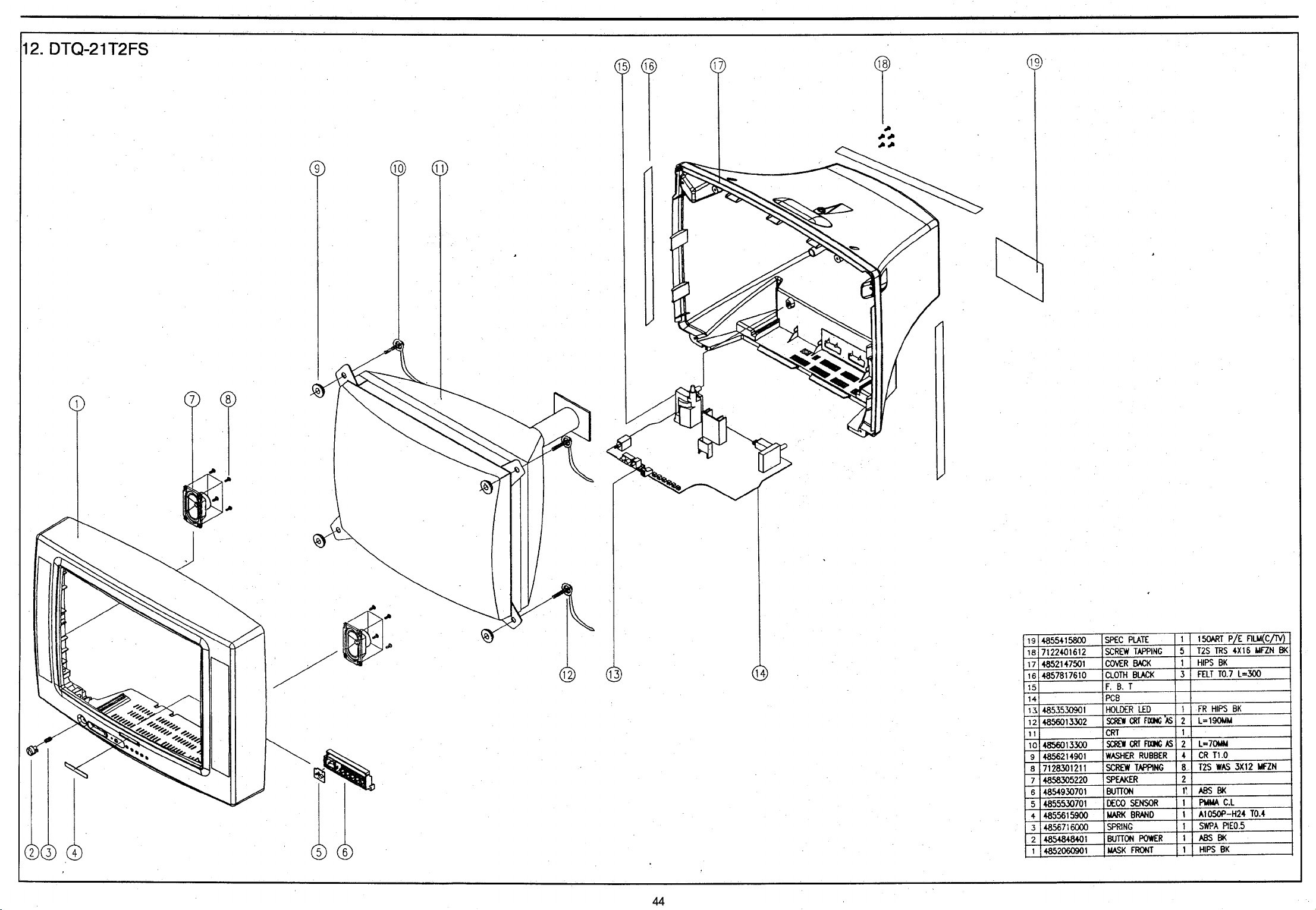


ENGINEER NOTE

DAEWOO ELECTRONICS CO., LTD.
686, AHYEON-DONG, MAPO-GU,
SEOUL, KOREA.
C.P.O. BOX 8003 SEOUL KOREA
TELEX : DWELEC K28177-8
F A X : (02) 364-5588,5305
T E L : (02) 360-7360
~
4, 7315 7
PRINTED DA TE:APR. 1998S/M NO :CN201N-010
~


 Loading...