

Page 1

1
CONTENTS
RUN AND CHECK UP....................................................................................................................................................2
WHERE TO INSTALL.....................................................................................................................................................3
INSTALLATION..............................................................................................................................................................3
INDOOR UNIT
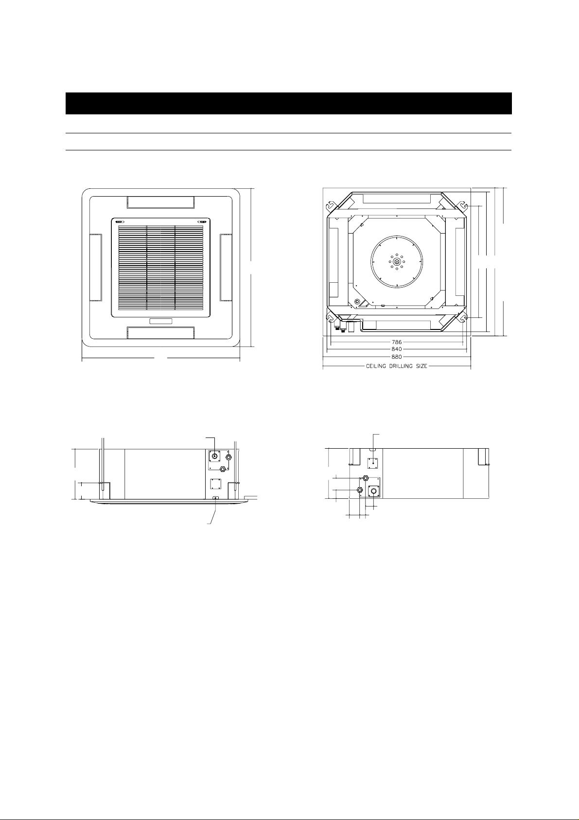
DIMENSIONS OF INDOOR UNIT [DTA-240LH]......................................................................................... 4
INDOOR UNIT INSTALLATION....................................................................................................................5
REFRIGERANT PIPE CONNECTION..........................................................................................................6
AIR PURGE...................................................................................................................................................6
REFRIGERANT SUPPLEMENT...................................................................................................................7
LEAK CHECKUP...........................................................................................................................................7
PIPE INSULATION AND ISOLATION...........................................................................................................7
DRAIN HOSE INSTALLATION .....................................................................................................................8
DRAINAGE TEST..........................................................................................................................................9
INDOOR UNIT WIRE CONNECTION.........................................................................................................10
OUTDOOR UNIT
OUTDOOR UNIT WIRE CONNECTION.....................................................................................................11
CHECKUP GROUNDING ...........................................................................................................................12
FRONT PANEL
FRONT PANEL INSTALLATION ................................................................................................................13
OWNER’S MANUAL.....................................................................................................................................................14
Page 2

RUN AND CHECK UP
2
Before the installation is carried out completely, check these out.
• Pipe connection and gas leaks
• Electric wiring and isolation treatment of drain pipes
• Drainage system and insulation treatment of drain pipes
• Grounding wire connection
Wire Remote Controller
1. Turn on the air conditioner. (If you can see the present temperature on the LCD of the wire remote controller, it means
the power supply is correctly connected.)
2. Set the mode 'Auto' and check if the outdoor unit is working properly.
(The outdoor unit runs 30 seconds after the first operation.)
3. Press the Fan Dir. button and check if regulating the angle of Flap is normal.
4. Complete the operation.
If any error occurs, ERR is shown on the wire remote controller.
Wireless Remote Controller
1. Turn on the air conditioner.(If you can see the present temperature on the LCD of the wire remote controller, it means
the power supply is correctly connected.)
2. Set the mode 'Auto' and check if the outdoor unit is working properly.(The outdoor unit runs 30 seconds after the first
operation.)
3. Complete the operation.
Page 3

WHERE TO INST ALL
3
Cautions before installation
• Read this manual thoroughly before you attempt to install the air conditioner.
• Drilling work through the ceiling must be done before installation.
• After installation, be sure to take a dry run and check if the machine is working properly.
• To avoid possible personal injury or property damage, be sure that installation will be done by instructed employees.
• In case that installation in those places as below is inevitable, contact an authorized company.
- Where the oily vapor or wheat flour is around
- Where the lubricating oil(such as cutting oil) is around
- Where inflammable gas flows in and remains.
- Where corrosive gas is produced or flows in and remains
- Where ducts are restricted to be installed
- Where surroundings of installation is not ordinary
Indoor Unit
• Where the unit can be sufficiently held up and no vibration is felt.(must receive the weight of more than 150kg)
• Where around the air inlet and outlet is clear.
• Where condenser water can be easily let out, and connecting pipes to the outdoor unit is easy.
• Where heat or vapor around the unit is clear(must be far away from kitchen or other heat sources)
• Where ceiling and floor is at a distance of lower than 3m.
• Where the unit can stand level with floor.
Outdoor Unit
• Out of rain or direct rays of the sun and well-ventilated
• Where not to bar the way
• Where the noise and heated air wouldn't disturb neighbourhood or animals and plants.
• Not to be installed on the outside railings of window or outside wall.
(to avoid possible personal injury and no after service available)
• Where pipes or wires can be easily connected to the unit.
• Where grounding is easy.
• Where installation distance is maintained long enough.
Page 4
4
INDOOR UNIT
664
940
250
250
7050
98
940
61.5 34.7
48
DRAIN OUTLET
DRAINAGE CHECKUP HOLE
POWER CORD
CONNECTING HOLE
840
880
CEILING DRILLING SIZE
DIMENSIONS OF INDOOR UNIT [DTA-240LH]
Page 5

5
1. Drill a hole with a depth of 880mm where the indoor
unit will be installed.
• Before carrying out installation, be cautious of the direction of drainage pipes and refrigerant pipes.
3. Bring the product fixing bolt together with nut and
washer as the figure shows.
• But the space for a hanger bracket to be inserted
must be secured.
4. Insert the hanger bracket between the fixed nuts on
the ceiling Suspension Bolt and hang the indoor unit.
2. Drill a hole through the ceiling or ceiling rest and insert the base bolt.
• In case that the bolt for supporting ceiling is over
1.5M, vibration isolation is needed.
Vibration isolating device is not included in product.
INDOOR UNIT INSTALLATION
5. Tighten the nuts and fix the indoor unit completely. 6. Select where to put the indoor unit, considering the
enough space the front panel can be fit in.
Product's level surface must be considered and adjust the level, and then fix the product.
Concrete
Anchor Bolt
for fixing product
Suspension Bolt
20
0~5mm
Suspension Bolt
nuts
Product fixing bracket
880
880
overhead
side
NUT
SPRING WASHER
BOLT
PLANE WASHER
Page 6

6
REFRIGERANT PIPE CONNECTION
AIR PURGE
If there is air or nitrogen gas which isn't to be condensed in the pipes, outflow pressure rise, power loss, condenser heating, and air conditioner deterioration might occur, and therefore air purge is essential.
Air purge is supposed to use the pulsometer pump, and can also use additional refrigerant in the unit.
• Refrigerant pipe connection
After finishing connecting the refrigerant piping,
check any refrigerant leak and wrap it with insulation
material, and cover it again with vinyl tape.
Tighten the flare nuts with torque rule.
1. Connect the pipes of indoor/outdoor units.
In carrying out this work, tighten the flare nut 4 rather
loosely.(screwable with hand)
2. Remove the cap nuts 8, 9, 10, and tighten the cap
nut 7 1~2 seconds after screwing it with a angle of 90
counterclockwise with hexagon wrench. In doing this
work, tight the flare nut 4 completely.
3. Press the nut 6 2~3 times(1 time/3 sec.) and vacuum
the air in the service valve completely.
4. Open the gas/liquid side service valves fully with use
of hexagon wrench.
Warning
• Use two spanners in connecting the union to the flare
nut.
• Do not bend the pipes more than twice and work on
the longer radius.
• Do not remove the cap on the flare until the clamping
is done.
INDOOR OUTDOOR
Page 7
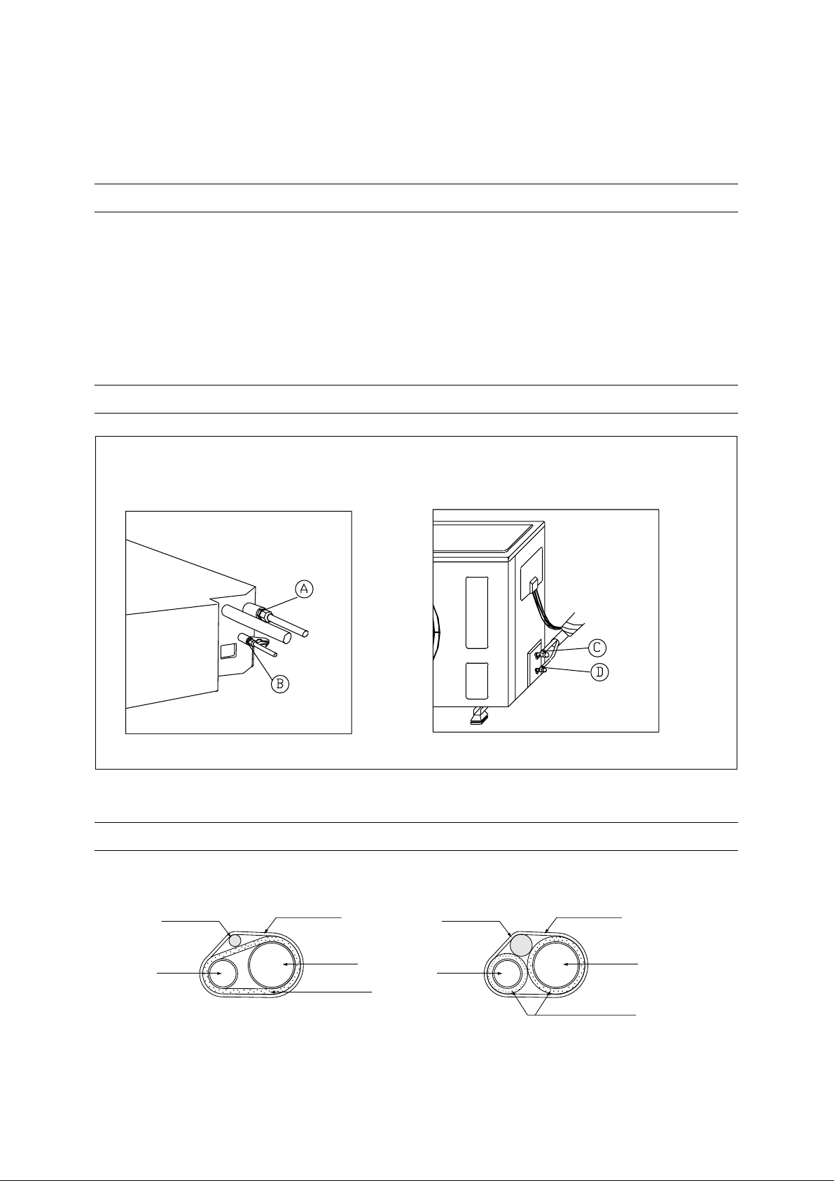
Indoor Unit
To check up gas leak, the end of flare nut
on A, B part.
Outdoor Unit
valve on C, D part
7
REFRIGERANT SUPPLEMENT
In case that the length of the refrigerant pipe is over 5m, refrigerant must be supplemented.(max.20m)
But the amount of the supplementary refrigerant is variable according to installing condition, so check the condition before supplementing refrigerant.
This work must be carried out by qualified employees.
• In case that vertical length is over 10m, install an oil trap on the gas pipes.
PIPE INSULATION AND ISOLATION
To prevent vapor from forming inside the pipes, insulate each pipe with heat-resisting polyethylrne resin.
Following figure shows how to insulate and isolate the refrigerant pipes correctly.
LEAK CHECKUP
ELECTRIC WIRE
PIPE LIQUID
FINISHING TAPE
PIPE GAS
ELECTRIC WIRE
PIPE LIQUID
FINISHING TAPE
PIPE GAS
PIPE INSULATION
PIPE INSULATION
(X) (O)
Page 8

8
DRAIN HOSE INSTALLATION
1. Drain hose connection
In case that the drain hose is connected, bonding
work is necessary for preventing leaks, and then
make it immovable with fixing stuff such as adhesive
band.(adhesive band is not included in product)
• outside diameter of drain hose connecting hole is
32mm
2. Insulating treatment
Insulating treatment must be carried out for the condenser water not to leak out from drain pipes.
Be sure there is no gap between the product and
hose.
• Inside diameter of flexible hose connecting hole is
32mm.
• In case that outside temperature and humidity is
high, make the insulating material by 10~30mm.
3. Supporting and connecting pipes
To let out the condenser water, drain pipes must be
at down-slope.
In case that drain pipes are not at down-slope, problems such as reverse flow of condenser water might
occur.
If the pipe is long, a rest that can support the pipe
needs to be installed.(to be worked within 1~1.5M)
4. Horizontal extension of pipe is impossible.
In case that drain hose is above the connecting hole,
it must be connected up to the hole at a right angle
within 30cm crossways from the product. Height of
the drain hose is at a right angle within 600mm from
the drain hose connecting hole.
Warning!
After connecting the flexible hose to the drain hose connecting hole, connecting the hose up at a right angle is
restricted.
outside diameter of
drain hose connecting
hole is 32mm
Drain hose
connecting hole
Insulation
Flexible
hose
main
body
bonding
work
adhesive band
(not included in
product)
drain
pipe
Main
body
pipe rest
pipe rest
down-slope(over 1/100)
elbow
25A VP
flexible hose
drain pipe
(with down-slope)
drain hose
connecting
hole
horizontal extension within
30cm is not impossible
within
60cm
overhead side
Page 9

9
DRAINAGE TEST
1. Remove the two bolts from checkup unit on the side
of drain pipe and detach the checkup cover.
2. Pour the prepared water inside the checkup unit.
• In case of failing to pour the water inside the checkup unit, water might overflow the product.
3. Check if the draining is normal.
pumping/draining
--->Checking drainage is available during turn-off,
cooling and heating.
4. Reinstall the checkup cover.
Page 10

10
INDOOR UNIT WIRE CONNECTION
DTA-240LH
3113544330
Page 11

11
OUTDOOR UNIT WIRE CONNECTION
OUTDOOR UNIT
Page 12

12
Attachments for grounding are not included in product.
1. Select proper place to install the grounding bar.
• For grounding, wet and solid ground is preferred to one covered with sand or pebbles.
• Select the place far away from gas/water pipes, telephone lines, underground cables, or other structures.
• The grounding must be carried out at least 2m from a lightening rod.
• A ground wire for telephone is not to be used for air conditioner.
2. Wrap the rest part of the pipe connected to the outdoor unit with the isolation tape and complete the grounding.
3. Install green or yellow ground wire.
• In case the ground wire is too short, extend the wire, wrapping the extended part with the isolation tape.
Don't bury the connected part.
• Fix the ground wire using a clamp.
In case the ground bar is installed where people pass, it must be fastened tight.
4. Connect the ground wire to the terminal plate on the outdoor unit.
CHECKUP GROUNDING
Page 13

13
FRONT PANEL INSTALLATION
1. Detach the inlet grille from the front panel. 2. Fasten two fixing screws for front panel diagonally to
the indoor unit by one third of each.
• Piping side mark of front panel must be fit together
with that of main body.
3. After fastening two screws, rotate the front panel to
be fixed on the edge of the key hole and fasten the
other two screws to be fixed completely.
4. Connect the cable of front panel to the PCB as the
figure shows.
5. Fasten the control box cover as the front panel
installed.
6. Close the front grille and fasten the fixing studs.
Control
bow cover
Page 14

BEFORE USE
14
Care and maintenance................................................................................................................................................15
Names of parts.............................................................................................................................................................16
Indoor Unit/Outdoor Unit......................................................................................................................................16
Wire remote controller..........................................................................................................................................17
Wireless remote controller...................................................................................................................................18
Replacing remote controller battery.....................................................................................................................19
How to use the wire remote controller......................................................................................................................20
Cool mode............................................................................................................................................................20
Heat mode............................................................................................................................................................20
Dehumidifier mode...............................................................................................................................................21
Fan mode.............................................................................................................................................................21
Auto mode............................................................................................................................................................21
Quick mode..........................................................................................................................................................22
Timer mode..........................................................................................................................................................22
Sleep mode..........................................................................................................................................................23
Fan direction/Fan speed controlling.....................................................................................................................23
How to use the wireless remote controller ..............................................................................................................24
Cool mode............................................................................................................................................................24
Heat mode............................................................................................................................................................24
Dehumidifier mode...............................................................................................................................................25
Fan mode.............................................................................................................................................................25
Auto mode............................................................................................................................................................25
Quick mode..........................................................................................................................................................26
Timer mode..........................................................................................................................................................26
Sleep mode..........................................................................................................................................................27
Fan speed controlling...........................................................................................................................................27
Cleaning the air filter...................................................................................................................................................28
Problems/Possible causes.........................................................................................................................................29
Specification ................................................................................................................................................................30
Page 15

15
CARE AND MAINTENANCE
Clean the casing and front of the indoor unit with a vacuum brush or wipe with a clean damp cloth.
• NEVER USE Solvents, harsh chemicals or hot water to clean the unit.
• Some metal edges on the unit are sharp. Be careful when cleaning or handling.
• Internal parts in the outdoor unit may need cleaning or routine maintenance from time to time. Consult your local ser-
vice center for more details.
AFTER THE SEASON:
• Operate the fan, then dry the indoor unit.
• Shut off the indoor unit and then unplug it from the wall.
• Clean the air filters.
• Cover the outdoor unit with the supplied cover; this is very important to protect this unit.
BEFORE THE SEASON:
• Make sure the air filters are clean.
• Make sure the inlet and outlet on the indoor and outdoor units are not blocked by obstructions.
• Make sure the unit is grounded. Consult a serviceman for help.
PRECAUTIONS:
• Do not use this unit for animal or plant storage.
• In a lightning or thunder storm, immediately unplug it from the wall.
warning
• Make sure the AC cord is unplugged and the unit is off before cleaning.
• Do not use water on the unit to clean it. This is a shock hazard and the unit can be damaged.
Page 16

16
INDOOR UNIT
Remote Controller Receiving
Part and Indicator
Heat Mode Indicator
• lit on during heating.
Remote Controller
Receiving Part
Cool mode Indicator
• lit on during cooling, fanning,
or dehumidifying.
Filter cleaning indicator
• shows when to clean the filter.
NAMES OF PARTS
Inlet Outlet
OUTDOOR UNIT
OUTDOOR UNIT AIR IN
- If there is any obstacle in front of
the grille, the efficiency of the unit
can be lowered.
OUTDOOR UNIT AIR OUT
SERVICE VALVES(GAS TUBE)
SERVICE VALVES(LIQUID TUBE)
CAUTION
• Do not install the outdoor unit on
unstable place like outside wall of
building or outside of balcony. In
case of falling, it may cause serious
trouble and damage.
Page 17

17
WIRE REMOTE CONTR OLLER
WIRE REMOTE CONTROLLER OPERATION INDICATOR
Power button
Mode button
Fan Speed button
Fan Direction button
Operation Indicator
Temperature Button
Timer button
(Enter/Cancel button)
Filter Reset button
Sleep button
Reservation Time Up button
Reservation Time Down button
Fan Mode Indicator
Dehumidifier Mode Indicator
Heat Mode Indicator
Filter Cleaning Indicator
Fan Dir.
Indicator
Cool Mode Indicator
Quick Mode Indicator
Auto mode Indicator
Fan Speed Indicator
Temperature Indicator
Timer Mode(Time) indicator
Sleep mode indicator
Page 18

18
MODE
SLEEP
ON/OFF
TIMER
ENTER/
CANCEL
FAN SPEED
Operation Indicator
Displays information
pertaining to unit.
Timer Enter/Cancel Button
Press to enter a timer setting or
to cancel timer setting
Timer On/Off Button
Press to set the unit off or on time.
(0.5, 1, 1.5, 2, 2.5, 3, 4, 5, 6, 8,
10, 12, 16, 20, 24hr)
Mode Button
Press to cycle through the modes
(Auto/Quick/Cool/Fan/Dehumidifier/
Heat)
Sleep Button
Press to set the unit for the
sleep mode.
On/Off Button
Press to turn the unit on or off.
Temperature Buttons
Fan Speed Button
Press to select the fan speed
(Auto, High " ", Middle " ",
Low " ", Natural).
Cover
Slide down to access most
of the remote buttons.
Slide down further to
access the battery
compartment.
AUTO
WIRELESS REMOTE CONTR OLLER
WIRELESS REMOTE CONTR OLLER OPERATION INDICATOR
Mode Indicators (Auto/Quick/Cool/Fan/Dehumidifier/Heat)
Lights to indicate the mode selected.
Timer Indicators (Include sleep)
Lights to indicate the timer function mode.
Temperature & Reservation Time lndicator
Lights to indicate the temperature or time.
Nantural Indicator
Lights to indicate the
speeds simulating a breeze.
Fan Indicators
Lights to indicate
the fan speed.
AUTO
Page 19

19
1. Lift the cap by pressing hard and pulling it in direction
of the arrow on the cap.
3. Close the cap by pushing it to the direction of the arrow.
2. Put the battery in to the direction of + and - inside of the
remote controller. Be sure the direction of + and -.
REPLACING REMOTE CONTROLLER B ATTERY
+–
+–
Page 20

20
• Cool mode
• Heat mode
• Dehumidifier mode
• Fan mode
• Auto mode
• Quick mode
• Timer mode
• Sleep mode
• Fan direction/Fan speed controlling
COOL MODE
• NOTES!
When the present temperature goes down to the desired temperature, the air conditioner retains the desired temperature, repeating cooling and fanning automatically.
• Press the Power Button and
turn the power on.
• Press the button till is
shown and the
Cool Mode starts.
• Yon can freely set the temperature between 18~32°C and the
temperature is set by 1°C with
each time the button pressed.
HEAT MODE
• NOTES!
When the present temperature goes up to the desired temperature, the air conditioner retains the desired temperature, repeating heating and fanning automatically.
• Press the Power button and
turn the power on.
Defrosting Mode
During the Defrosting Mode, in case that outdoor temperature is low and humidity is high, the outdoor unit gets
covered with frost and it deteriorates the heating function. During the Defrosting mode, pre-heating mode is applied until temperature of the outdoor unit pipe goes up to proper temperature.
During the Defrosting Mode, indoor unit doesn't work.
• Press the button till is
shown and the
Heat Mode starts.
• Yon can freely set the temperature between 18~32°C and the
temperature is set by 1°C with
each time the button pressed.
HOW TO USE THE WIRE REMOTE CONTROLLER
Page 21

21
DEHUMIDIFIER MODE
• NOTES!
During the Dehumidifier Mode, Cool Mode indicator on the front panel gets lit on.
During the Dehumidifier Mode, Fan speed is automatically set on "Low".
• Press the power button and
turn the power on.
• Press the button till is
shown and the
Dehumidifier Mode starts.
• Yon can freely set the temperature between 18~32°C and the
temperature is set by 1°C with
each time the button pressed.
AUTO MODE
• NOTES!
With Auto Mode applied, cooling, heating, or dehumidifying is automatically set into run.
• Press the power button and
turn the power on.
• Press the button till is
shown and the Auto Mode
starts.
• Yon can freely set the temperature between 24~28°C and the
temperature is set by 1°C with
each time the button pressed.
FAN MODE
• NOTES!
During the Fan Mode, Cool Mode Indicator on the front panel gets lit on.
During the Fan Mode, temperature isn't able to be set.
During the Fan Mode, pleasant air comes out insteand of cool/heal air.
• Press the power button and turn the power on.
• Press the button till is shown and the
Fan Mode starts.
Page 22

22
QUICK MODE
• Notes!
With Quick Mode applied, cooling or heating is set to work more swiftly.
During Quick Mode, cooling or heating is automatically set.
During Quick Mode, temperature or fan speed isn't able to be set.
• Press the power button and turn the power on.
• Press the button till is shown and the
Quick Mode starts.
TIMER MODE
• Notes!
When the reservation time is over, the air conditioner is running under the previously selected mode.
• Notes!
When the reservation time is over, the running mode stops.
Timer On is available only
when the air conditioner isn't
running.
Timer Off is available only
when the air conditioner is
running.
• Press the button and select
timer mode.
• Press the button and set the
reservation time.
• Reservation time can be set in
the order of 0.5, 1, 1.5, 2, 2.5, 3,
4, 5, 6, 8, 10, 12, 16, 20, 24 hr.
• Press the button and select
timer mode.
• Press the button and set the
reservation time.
• Reservation time can be set in
the order of 0.5, 1, 1.5, 2, 2.5, 3,
4, 5, 6, 8, 10, 12, 16, 20, 24 hr.
How to cancel the reservation,
With the reservation time set, press the button and the reservation is canceled.
'Timer' on the Timer Mode(Time) indicator disappears.
Page 23

23
SLEEP MODE
• Notes!
When Sleep Mode starts, 'SLEEP 4.0 HOUR’ is shown on the Sleep mode indicator.
Operation is turned off 4 hours after the Sleep Mode is applied.
Sleep Mode is not working during Fan Mode and Quick Mode.
Sleep Mode is available only when
the air conditioner is turned on.
• Press the button and the Sleep Mode starts.
FAN SPEED CONTROLLING
By pressing the button, Fan Speed can be regulated
as below.
•
During Auto, Cool, Heat and Dehumidifier Mode
:
Auto-> Low-> Middle-> High-> Natural
• During Quick Mode: 'High' fan speed Only
• During Fan Mode:
Low-> Middle-> High-> Natural
• With Auto Fan Speed applied, fan speed can be au-
tomatically regulated according to temperature.
How to cancel the mode,
Press the button again and the reservation is canceled.
FAN DIRECTION CONTROLLING
By pressing the button, Fan Direction can be regulated.
• To make the angle of FLAP half open, press the button, and to make it fully open, press the button twice.
Pressing the button once more changes it "Middle",
and by pressing the button again, it is set on
"Narrow".
Narrow
→ Middle → Wide → Middle
→
Narrow
Middle
Wide
Page 24

24
• Cool mode
• Heat mode
• Dehumidifier mode
• Fan mode
• Auto mode
• Quick mode
• Timer mode
• Sleep mode
COOL MODE
• NOTES!
When the present temperature goes down to the desired temperature, the air conditioner retains the desired temperature, repeating cooling and fanning automatically.
• Press the Power Button and
turn the power on.
• Press the button till is
shown and the
Cool Mode starts.
• Yon can freely set the temperature between 18~32°C and the
temperature is set by 1°C with
each time the button pressed.
HEAT MODE
• NOTES!
When the present temperature goes up to the desired temperature, the air conditioner retains the desired temperature, repeating heating and fanning automatically.
• Press the Power button and
turn the power on.
Defrosting Mode
During the Defrosting Mode, in case that outdoor temperature is low and humidity is high, the outdoor unit gets
covered with frost and it deteriorates the heating function. During the Defrosting Mode, pre-heating mode is applied until temperature of the outdoor unit pipe goes up to proper temperature.
During the Defrosting Mode, indoor unit doesn't work.
• Press the button till is
shown and the
Heat Mode starts.
• Yon can freely set the temperature between 18~32°C and the
temperature is set by 1°C with
each time the button pressed.
HOW TO USE THE WIRELESS REMOTE CONTROLLER
Page 25

25
DEHUMIDIFIER MODE
• NOTES!
During the Dehumidifier Mode, Cool Mode indicator on the front panel gets lit on.
During the Dehumidifier Mode, Fan speed is automatically set on "Low".
• Press the power button and
turn the power on.
• Press the button till is
shown and the
Dehumidifier Mode starts.
• Yon can freely set the temperature between 18~32°C and the
temperature is set by 1°C with
each time the button pressed.
AUTO MODE
• NOTES!
With Auto Mode applied, cooling, heating, or dehumidifying is automatically set into run.
• Press the power button and
turn the power on.
• Press the button till is
shown and the Auto Mode
starts.
• Yon can freely set the temperature between 24~28°C and the
temperature is set by 1°C with
each time the button pressed.
FAN MODE
• NOTES!
During the Fan Mode, Cool Mode Indicator on the front panel gets lit on.
During the Fan Mode, temperature isn't able to be set.
During Fan Mode, pleasant air comes out instead of cool air.
• Press the power button and turn the power on.
• Press the button till is shown and the
Fan Mode starts.
Page 26

26
QUICK MODE
• Notes!
With Quick Mode applied, cooling or heating is set to work more swiftly.
During Quick Mode, cooling or heating is automatically set.
During Quick Mode, temperature or fan speed isn't able to be set.
• Press the power button and turn the power on.
• Press the button till is shown and the
Speedy Mode starts.
TIMER MODE
• Notes!
When reservation time is set, 'TIMER' is shown on the Temperature & Reservation Time indicator.
The range of reservation time is from 30min. to 24hr.
Timer On is available only when the air conditioner is turned off.
When the reservation time is over, the air conditioner is running under the previously selected mode.
• Notes!
When the reservation time is over, the running mode stops.
Timer On is available only
when the air conditioner isn't
running.
• Press the button and set the
reservation time.
• Reservation time can be set
in the order of 0.5, 1, 1.5, 2,
2.5, 3, 4, 5, 6, 8, 10, 12, 16,
20, 24 hr
• Press the button to input the
setting into memory while
'TIMER' is blinking on the
Temperature & Reservation
Time indicator.
Timer Off is available only
when the air conditioner is
running.
• Press the button and set the
reservation time.
Reservation time can be set
in the order of 0.5, 1, 1.5, 2,
2.5, 3, 4, 5, 6, 8, 10, 12, 16,
20, 24 hr
• Press the button to input the
setting into memory while
'TIMER' is blinking on the
Temperature & Reservation
Time indicator.
How to cancel the reservation,
During the Timer Mode, press the button and the reservation is canceled.
'Timer' on the Temperature & Reservation Time indicator disappears.
Page 27

27
SLEEP MODE
• Notes!
When Sleep Mode starts, '4 HOUR OFF' is shown on the display.
Operation is turned off 4 hours after the Sleep Mode is applied.
Sleep Mode is not working during Fan Mode and Qucik Mode.
Sleep Mode is available only when the air
conditioner is turned on.
• Press the button and the Sleep Mode starts.
How to cancel the mode,
Press the button again and the reservation is canceled.
FAN SPEED CONTROLLING
By pressing the button, Fan Speed can be regulated as below.
•
During Auto, Cool, Heat and Dehumidifier Mode
: Auto-> Low-> Middle-> High-> Natural
• During Quick Mode: 'High' fan speed Only
• During Fan Mode:
Low-> Middle-> High-> Natural
• With Auto Fan Speed applied, fan speed can be automatically regulated according to temperature.
Page 28

28
1. For your safety, disconnect the plug or turn off the
main power supply switch before cleaning.
2. To take the air filter out, loosen the fixing studs on
each side of air inlet and open the front grille.
3. Use a vacuum cleaner or soft brush to clean it.
In case that the air filter is heavily polluted, rinse it
using water heated below 40°C and commercially
available neutral detergent.
Dry the air filter in the shade, avoiding the direct rays
of the sun.
4. In assembling, fix the air filter in and close the front
grille, and then fasten the fixing studs.
5. Finishing cleaning the air filter, press the Filter Reset
button on the wire remote controller.
Notes!
• The products of our company let you know when to
clean the air filter, with automatic sensor.
• When it's time to clean the air filter, the indicator
on the wire remote controller gets lit on.
• It is desirable to clean the air filter more than once a
month.
• It could deteriorate the efficiency of air conditioner
not to clean the air filter.
CLEANING THE AIR FIL TER
Page 29

29
PROBLEMS/POSSIBLE CAUSES
Problems
• The air conditioner isn't
working at all.
• You can't regulate the
temperature.
• Air does blow out, but
when cool/hot air doesn't
come out.
• You can't set the fan
speed.
• The wireless remote controller isn't working.
• Strange sound from the
air conditioner
• Dew forms around the air
outlet.
• Cool/Heat Mode Indicator
is blinking.
Possible Causes
• Isn't the power switch blocked?
• Isn't the Fuse cut off?
• Hasn't the power gone off?
• Is the remote controller working nor-
mally?
• Isn't the Fan or Quick Mode applied?
• Isn't the Fan Mode applied?
• Isn't the air filter clogged?
• Is there any obstacle around the
outdoor unit?
• Isn't the air conditioner affected by
the direct rays of the sun?
• Isn't the air conditioner turned on after being turned off?
• Isn't the desired temperature higher
or lower than present temperature?
• Isn't the Quick Mode or Dehumidifier
Mode applied?
• Isn't the battery low?
• Is it clear near the remote controller
receiving part on the indoor unit?
• Has the air conditioner been turned
on long enough to work normally?
• Is the humidity in the room normal?
Troubleshooting
• Turn on the main supply switch
again.
• Replace the fuse with one which
meets standard requirements.
• Check out other electric appliances.
• Check out if the battery polarity is ac-
curate and replace it with new one.
• Temperature is not supposed to be
set during Fan/Quick Mode.
• Try Cool/Heat Mode.
• Clean the air filter following the air fil-
ter maintenance.
• Heat exchange isn't working normally. Remove the obstacles.
• Window shade is needed.
• Don't worry. In case that the air con-
ditioner is turned on right after being
turned off, for the protection of air
conditioner, the outdoor unit doesn't
work for 3 minutes.
• Regulate proper desired temperature.
• In this case, fan speed is set automatically, so you don't need to regulate it.
• Replace the battery with new one.
• Remove the obstacles.
• The change in the sound could be
caused by a change in the current of
cooling gas according to modes,
which is normal.
• Dew could be formed by the moisture
in the air. Wipe it with a dry towel.
• Please contact the authorized service
center or appliance distributor you
purchased.
Page 30

30
SPECIFICATION
MODEL DTA -240LH
Type Thru-the-Ceiling cassette Cool/Heat air conditioner
Power Supply Single phase AC 220V/60Hz
Conditions By JIS C9812
Cooling capacity 24000 Btu/h
Heating capacity 24000 Btu/h
Power Consumption (Cooling/Heating) 2700W / 2400W
Operating Current (Cooling/Heating) 13A / 12A
Refrigerant R22, 1.8Kg
Net Weight (Indoor/Outdoor) 36kg / 61kg
Dimensions of Units (Indoor/Outdoor) 840mm x 840mm x 250mm / 872mm x 675mm x 325mm
Dimensions of Front Grille 940mm x 940mm x 30mm
Operating
Operating
Indoor side (Heating Mode) min 21˚C ~ max 32˚C (min 15°C ~ max 27°C)
Condition
Outdoor side (Heating Mode) min 21˚C ~ max 54˚C (min -2°C ~ max 24°C)
Design and specification are subject to change without notice for product improvement.
S/N: 3113909110
Page 31

MODEL #:
DTA-240LH
Made in Korea
INSTALLATION AND
OWNER'S MANUAL
 Loading...