

Page 1
Exploded Views and Parts List
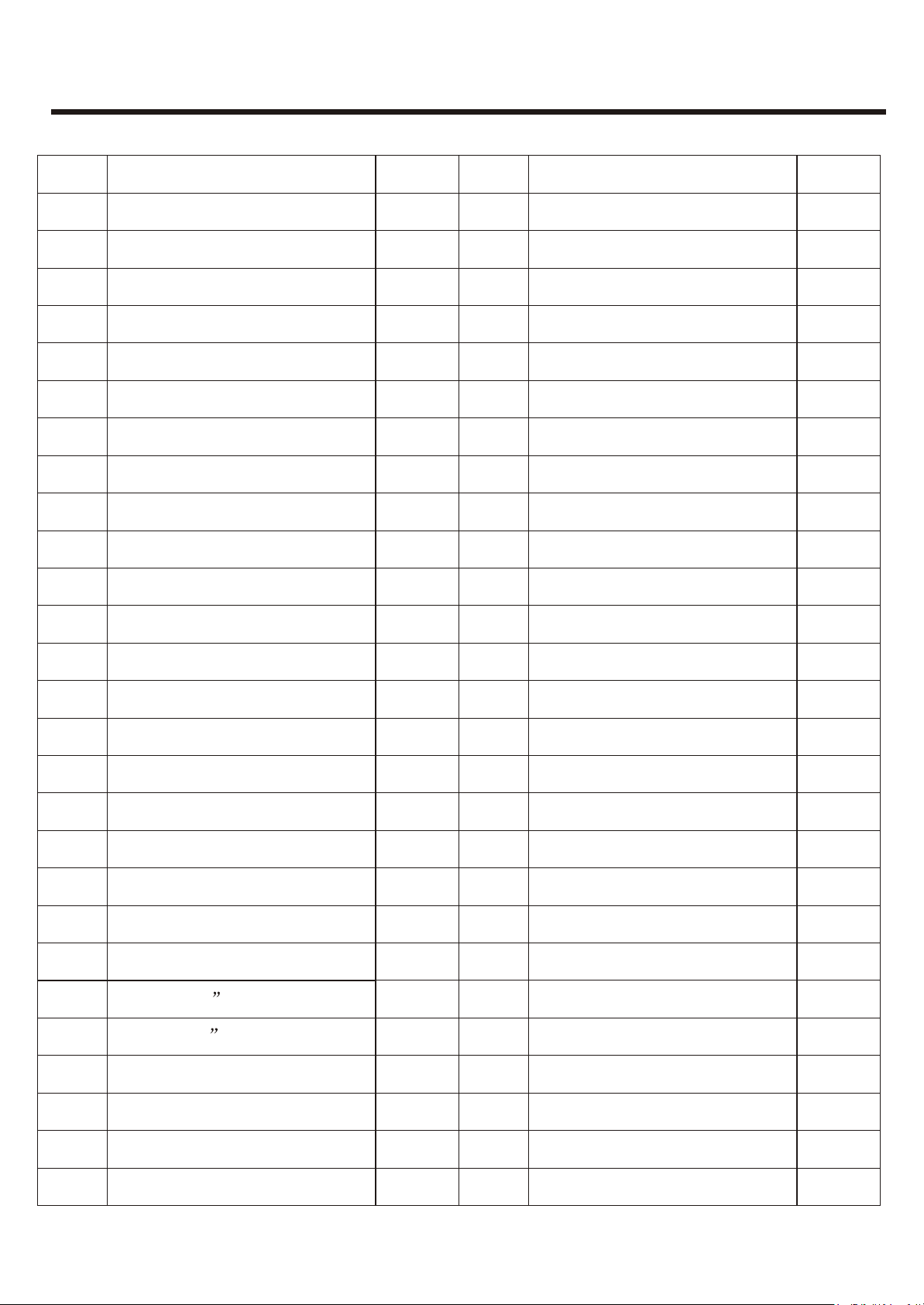
Outdoor unit
Number
1
2
3
4
5
6
7
8
9
10
11
Air outlet grille
Axial flow fan motor
Capacitor splint
Name
Front plated
Trademark
Axial flow fan
Motor support
Condesator
Handle
Top cover
Back coer
Quantity
2
1
2
2
2
1
1
1
1
1
1
Model: DSB-077/097/127LH
Number
28
29
30
31
31-1
31-2
31-3
31-4
31-5
31-6
Name
Compressor
Airtight cushion
Compressor terminal cover
Wire assembly in the outdoor unit
Compressor wire
Pipe temperature sensor
Grounding wire of the compressor
Grounding wire of the outdoor unit
wire of the compressor capacitor
wire of the fan motor
Quantity
1
1
1
1
1
1
1
1
1
1
12
13
14
15
16
17
18
19
20
21
22
23
Capacitor of the compressor
Electrical appliance cover
Connecting cable clip
Outdoor unit terminal
Capacitor of the outdoor unit motor
Electrical appliance holder
Solenoid
Capillary assembly
Pipe assembly
Baffle plate
1/4 on-off valve
1/2 on-off valve
1
1
1
1
1
1
1
1
1
1
1
1
4141
24
25
26
27
On-off valve holder
Base plate
Rubber shock absorption
Cage nut
1
1
1
1
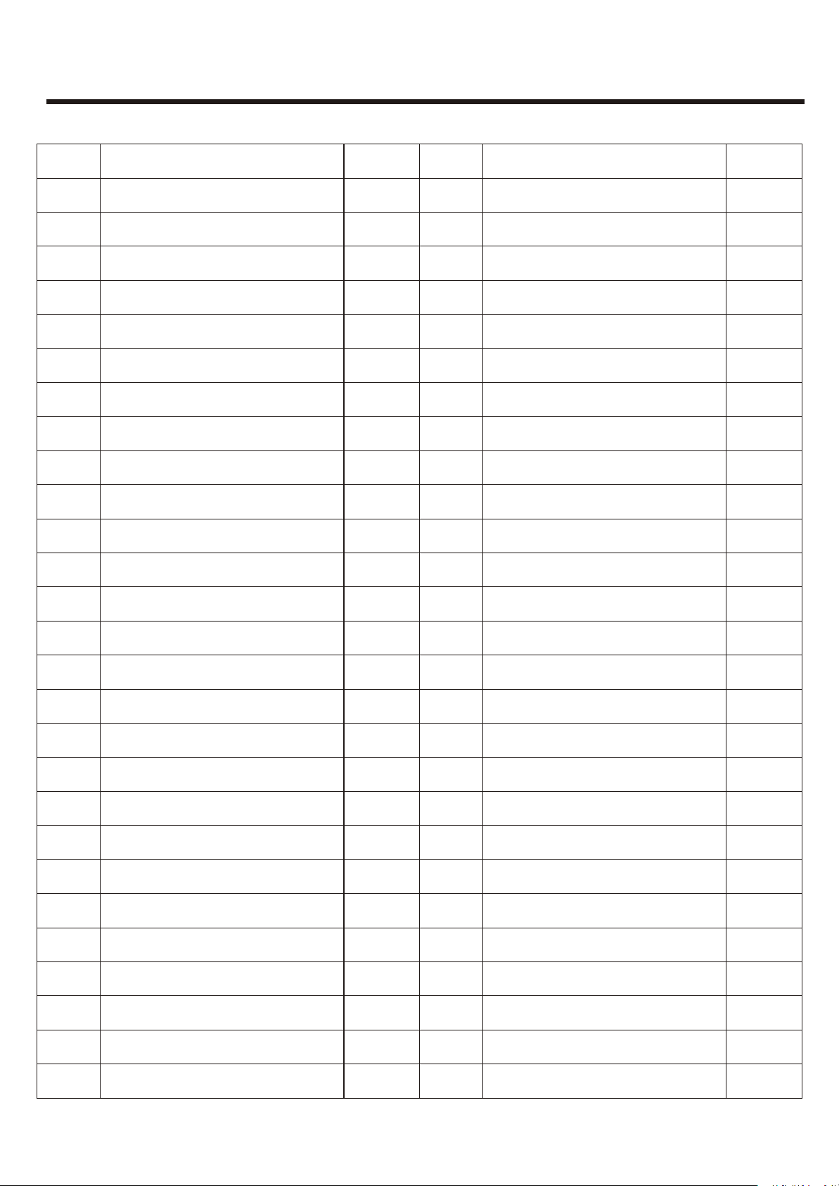
Page 2
Exploded Views and Parts List
Indoor unit
24
25
26
27
32
23
20
9
18
19
21
22
10
Model: DSB-187LH
17
16
15
14
12
11
13
31
28
29
30
8
7
6
5
4
3
2
1
33
33-1
33-2
33-3
33-4
33-5
33-6
4242
Page 3
Exploded Views and Parts List
Indoor unit
Number
1
2
3
4
5
6
7
8
9
10
11
Indicator light cover
Terminal cover
Airflow direction louver
Indoor fan motor
Pipe temperature sensor
Operation indicator
Name
Dustproof filter
Front panel
Encloser
Drain hose
Louver motor
Quantity
2
3
4
1
1
1
1
1
2
1
1
Number
28
29
30
31
32
32-1
32-2
32-3
32-4
32-5
32-6
Model: DSB-187LH
Name
Air outlet vent assembly
Drain cap
Screw cover
Art strip
Internal wire ass’y
Internal grouding wire
The 4th terminal wire
The 1st terminal wire
The 2nd terminal wire
The 3th terminal wire
Pipe temperature sensor
Quantity
1
1
1
1
1
1
1
1
1
1
1
1
12
13
14
15
16
17
18
19
20
21
22
23
Remote signal recetor
Power supply cord
High voltage control board
Lower voltage control board
Control box
Transfomer
Indoor unit terminal
Connecting cable fixed holder
Indicator light holder
Power supply cord clip
Room temperature sensor
Pipe fixed board
1
1
1
1
1
1
1
1
1
1
1
1
4343
24
25
26
27
Hanging plate
Back body
Indoor unit fan
Rubber bearing
1
1
12
1
Page 4
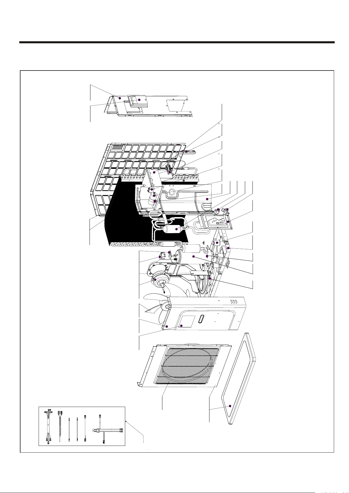
Exploded Views and Parts List
Outdoor unit
Model: DSB-187LH
13
15
16
17
19 18
21
23
22
20
12 14
24
25
26
11
10
9
8
7
6
5
4
27
28
29
30
3
2
1
31-1
31-2
31-4
31-3
3 311
31-5
31-6
31
4444
Page 5

Exploded Views and Parts List
Outdoor unit
Number
1
2
3
4
5
6
7
8
9
10
11
Compressor terminal cover
Left front plate
Air outlet grille
Right front plate
Axial flow fan motor
Airtight cushion
Name
Top cover
Trademark
Axial flow fan
Motor support
Condeser
Quantity
1
1
1
3
3
1
1
1
2
1
1
Number
28
29
30
31
31-1
31-2
31-3
31-4
31-5
31-6
Model: DSB-187LH
Name
Cage nut
Compessor
Pipe assembly support
Compressor connective wire
Pipe temperature sensor
Grounding wire of the compressor
Grounding wire of the outdoor unit
Wire of the compressor capacitor
wire of the fan motor
Quantity
26
12
4
4
1
1
1
1
1
1
1
12
13
14
15
16
17
18
19
20
21
22
23
24
Back cover
Right plate
Handle
Electrical appliance holder
Capillary assembly
Outdoor unit terminal
Capacitor of the fan motor
Capacitor of the compressor
Capacitor splint
Baffle plate
4-way valve assembly
1/4 on-off valve
1/2 on-off valve
1
1
1
1
1
1
1
1
1
1
1
1
1
4545
25
26
27
On-off valve holder
Rubber shock absorption
Base plate
1
1
1
Page 6

Exploded Views and Parts List
Indoor unit
Model:DSB-247LH
1
2
3
4
5
6
7
8
9
10
11
12
13
14
15
16
17
19
20
21
22
18
4646
Page 7

Exploded Views and Parts List
Indoor unit
Number
1
2
3
4
5
6
7
8
9
10
11
Indicate light cover
Indicate light board
Left cover of evaporator
Left cover of evaporator
Motor install board
Indoor fan capacitor
Name
Front panel
Encloser
Screw cover
Evaporator
Transformer
Quantity
1
1
1
1
1
3
1
1
1
1
1
Number
Model :DSB-247LH
Name
Quantity
12
13
14
15
16
17
18
19
20
21
22
Clip
Electrical control PCB
Fan motor
Indoor unit fan
Electrical box
Pipe fixed board
Bottom body
Hanging plate
Air outlet vent support assembly
Step motor
Filter
1
1
1
1
1
1
1
1
1
1
2
4747
Page 8

Exploded Views and Parts List
Outdoor unit
Model: DSB-247LH
2626
1414
1313
1515
2828
2727
3030
2929
1616
1717
1818
1919
2020
2121
1212
1111
1010
99
88
77
66
55
44
22
22
33
22222323
2424
11
2525
11
4848
Page 9

Exploded Views and Parts List
Outdoor unit
Number
1
2
3
4
5
6
7
8
9
10
11
air outlet grill
Left front plate
Left back plate
Condensator
Motor fixed plate
Fan motor holder
Condensator fixed clip
Electrical control box
Partition
Back cover
Name
Handle
Quantity
2
1
3
1
1
2
1
1
1
1
1
Number
28
29
30
Model :DSB-247LH
Name
Contactor
Terminal block 1
Terminal block 2
Quantity
1
1
1
4
12
13
14
15
16
17
18
19
20
21
22
23
24
Top cover
Right cover
Right front plate
Trademark
Right bottom cover
Terminal cover
Washer
Compressor
Electrical control cover
Bottom body
Fan motor
Outdoor unit fan
High pressure valve
1
1
1
1
1
1
1
1
1
1
1
1
1
4949
25
26
27
Low pressure valve
Compressor capacitor
Fan motor capacitor
1
1
1
Page 10

Exploded Views and Parts List
Remote controller
11
22
77
33
8 8
44
55
99
1010
66
1111
Number
1
2
3
4
5
6
7
8
9
10
11
Name
Inlay LCD
case up
LCD screen
Conduct rubber
Ass’y PCB remocon
Back body
Spring battery
Conduct rubber
Spring battery
Screw
Back cover
Quantity
1
1
1
1
1
1
1
1
1
4
1
5050
Page 11

Wiring diagram
Model:DSB-077/097/127LH
REMOTE
CONTROLLER
CNW1
RECEIVER
CNW2
DISPLAY
BOARD
¦È¦È
¦È¦È
INDOOR UNIT WIRING DIAGRAM
FAN MOTOR
LOUVER
MOTOR
33
CN-RCV
44
CN-DISP
ROOM THERMISTOR
PIPE THERMISTOR
MV
BLU
CN-STM
CN-C
ELECTRONIC CONTROL
P.C BOARD
CNF3
CNF5
(RT)
(PT)
CN-Y
RED
CN-T
BLK
RED
AC220V AC13.5V
MF
RED
BLK
ORN
CN-FM
COMPRESSOR
RELAY
CNF4
(OP)
BLK
YLW
GRY
RY-HOT1
YLW
44
33
AC1-N
RY-W1
BLU
RED
TRANSFORMER
MASTER
SWITCH
BRN
BLU
YLW/GRN
YLW/GRN
BLU
WHT
RED
YLW
TERMINAL
BED
BLK
BLK
CONNECTOR
POWER
SOURCE
TO OUTDOOR
NN
22
33
44
BRN
BLU
L
N
UNIT
OUTDOOR UNIT WIRING DIAGRAM
TO INDOOR
UNIT
TERMINAL
BED
BLU
NN
WHT WHT
22
YLW
33
44
R1R1
R2R2
YLW/GRN
BLU
BLK
BLK
BLU
SOLENOIDE
COIL
RED
MF
YLW/GRN
¦È¦È
THERMISTOR
BLU
BLU
BLUYLW
COMPRESSOR
FAN MOTOR
RUN
CAPACITOR
WHT RED BLU
S
C
R
MC
MOTOR
YLW/GRN
51
Page 12

Wiring diagram
Model:DSB-187LH
INDOOR UNIT WIRING DIAGRAM
REMOTE
CONTROLLER
CNW1
RECEIVER
CNW2
DISPLAY
BOARD
ROOM THERMISTOR
¦È¦È
PIPE THERIMSTOR
¦È¦È
LOUVER
3
CONTROL
4
MOTOR
CN-RCV
MAIN
P.C.B
CN-DISP
CNF3
CNF5
(RT)
(PT)
MVMV
CN-STM
CNF4
(OP)
BLU
RED
CN-C CN-FM
POWER SUPPLY
P.C.B
12
CN-Y
RED
AC220V
TRANSFORMER
FAN MOTOR
MFMF
BLK
ORN
GRY
YLW
COMPRESSOR
RELAY
CN-T
BLK
RED
BLK
AC13.5V
4
3
AC1-N
RY-HOT RY-W1
YLW
RED
MASTER
SWITCH
YLW/GRN
BLU
WHT
BLU
RED
YLW
CONNECTOR
BLK
POWER
SOURCE
BRN
BLU
YLW/GRN
TO OUTDOOR
UNIT
NN
22
33
44
TERMINAL
BED
BRNBLK
BLU
L
N
TO INDOOR
UNIT
TERMINAL
CONNECTOR
OUTDOOR UNIT WIRING DIAGRAMOUTDOOR UNIT WIRING DIAGRAM
YLW/GRN
BLU
BLU
NN
22
33
44
BED
WHT
BLK
BLU
BLK
BLK
SOLENOIDE
COIL
BLU
BLK
44
BLK
ORN
WHT
WHT
WHT
RED
2233
11
RED
ORN
COMPRESSOR
MFMF
¦È¦È
THERMISTOR
YLW/GRN
FAN MOTOR
BLU
WHT
C
MCMC
MOTOR
RUN
CAPACITOR
BLU
BLU
RED
S
R
YLW/GRN
52
Page 13

Wiring diagram
Model:DSB-247LH
INDOOR UNIT WIRING DIAGRAM
REMOTE
CONTROLLER
LOUVER
MOTOR
MV
FAN MOTOR
MF
YLW/GRN
POWER
SOURCE
BRN
BLU
YLW/GRN
L
N
CN-DISP1
DISPLAY
RECEIVER
BOARD
ROOM THERMISTOR
¦È
PIPE THERMISTOR
¦È
OUTDOOR UNIT WIRING DIAGRAM
TO
INDOOR
UNIT
4
L1
L
L2
2
L3
N
2
3
4
R1
5
R2
6
BLK
CN-STM
CN-DISP
CN-C
CN-FM
ELECTRINIC CONTROL
P.C BOARD
PTRT
TRANS
RED
BRN
BLU
BLU
YLW/GRN
HIGH PRESSURE SWITCH
WHT
BLK
BLU
BLK
SOLENOIDE
¦È
THERMISTOR
RED
AC220V
TRANS1
BLK
AC13.5V
HOT OUT
BLK
YLW
TRANSFORMER
CONTACTOR SWITCH
CONTACTOR
COIL
BLU
COIL
BLK
BLK
N
R
G
/
W
BLK
YL
ORN
WHT
MF
AC L IN
AC N IN
COM OUT
WFAN OUT
OT
BRN
YLW/GRN
REACTOR
BLK
WHTWHT
RED
RED
WHT
C
ORN
124 3
ORN
COMPRESSOR
FAN MOTOR
YLW/GRN
BLU
CAPACITOR
RED
S
MC
MOTOR
BRN
L
BLU
WHT
RED
TO
N
OUTDOOR
2
UNIT
3
TERMINAL
BLOCK
BRN
1
1
ORN
2
2
YLW
3
3
4
4
CONNECTOR
BLU
BLU
R
N
GR
W/
L
Y
53
 Loading...